EP3418859A1 - Information processing apparatus, method of canceling prohibition, and carrier means - Google Patents
Information processing apparatus, method of canceling prohibition, and carrier means Download PDFInfo
- Publication number
- EP3418859A1 EP3418859A1 EP18178295.4A EP18178295A EP3418859A1 EP 3418859 A1 EP3418859 A1 EP 3418859A1 EP 18178295 A EP18178295 A EP 18178295A EP 3418859 A1 EP3418859 A1 EP 3418859A1
- Authority
- EP
- European Patent Office
- Prior art keywords
- application
- information processing
- program
- prohibition
- processing apparatus
- Prior art date
- Legal status (The legal status is an assumption and is not a legal conclusion. Google has not performed a legal analysis and makes no representation as to the accuracy of the status listed.)
- Granted
Links
Images




Classifications
-
- H—ELECTRICITY
- H04—ELECTRIC COMMUNICATION TECHNIQUE
- H04N—PICTORIAL COMMUNICATION, e.g. TELEVISION
- H04N1/00—Scanning, transmission or reproduction of documents or the like, e.g. facsimile transmission; Details thereof
- H04N1/00885—Power supply means, e.g. arrangements for the control of power supply to the apparatus or components thereof
- H04N1/00888—Control thereof
- H04N1/00896—Control thereof using a low-power mode, e.g. standby
-
- G—PHYSICS
- G06—COMPUTING OR CALCULATING; COUNTING
- G06F—ELECTRIC DIGITAL DATA PROCESSING
- G06F1/00—Details not covered by groups G06F3/00 - G06F13/00 and G06F21/00
- G06F1/26—Power supply means, e.g. regulation thereof
- G06F1/32—Means for saving power
- G06F1/3203—Power management, i.e. event-based initiation of a power-saving mode
- G06F1/3206—Monitoring of events, devices or parameters that trigger a change in power modality
-
- G—PHYSICS
- G06—COMPUTING OR CALCULATING; COUNTING
- G06F—ELECTRIC DIGITAL DATA PROCESSING
- G06F3/00—Input arrangements for transferring data to be processed into a form capable of being handled by the computer; Output arrangements for transferring data from processing unit to output unit, e.g. interface arrangements
- G06F3/12—Digital output to print unit, e.g. line printer, chain printer
- G06F3/1201—Dedicated interfaces to print systems
- G06F3/1202—Dedicated interfaces to print systems specifically adapted to achieve a particular effect
- G06F3/1218—Reducing or saving of used resources, e.g. avoiding waste of consumables or improving usage of hardware resources
- G06F3/1221—Reducing or saving of used resources, e.g. avoiding waste of consumables or improving usage of hardware resources with regard to power consumption
-
- G—PHYSICS
- G06—COMPUTING OR CALCULATING; COUNTING
- G06F—ELECTRIC DIGITAL DATA PROCESSING
- G06F3/00—Input arrangements for transferring data to be processed into a form capable of being handled by the computer; Output arrangements for transferring data from processing unit to output unit, e.g. interface arrangements
- G06F3/12—Digital output to print unit, e.g. line printer, chain printer
- G06F3/1201—Dedicated interfaces to print systems
- G06F3/1223—Dedicated interfaces to print systems specifically adapted to use a particular technique
- G06F3/1229—Printer resources management or printer maintenance, e.g. device status, power levels
-
- H—ELECTRICITY
- H04—ELECTRIC COMMUNICATION TECHNIQUE
- H04N—PICTORIAL COMMUNICATION, e.g. TELEVISION
- H04N1/00—Scanning, transmission or reproduction of documents or the like, e.g. facsimile transmission; Details thereof
- H04N1/44—Secrecy systems
- H04N1/4406—Restricting access, e.g. according to user identity
- H04N1/4433—Restricting access, e.g. according to user identity to an apparatus, part of an apparatus or an apparatus function
Definitions
- the present disclosure relates to an information processing apparatus, a method of canceling prohibition, and carrier means such as a recording medium.
- an apparatus has the plurality of operation modes, such as a power-saving mode (energy-saving mode) and a non-power-saving mode (e.g., normal mode).
- the power-saving mode is defined as a mode in which the apparatus stops supplying a power to some or all of the hardware resources to save the power consumption.
- Some apparatuses implement a transition to the power-saving mode using a program-based control.
- abnormality may occur to the program-based control.
- some apparatuses have a mechanism of enabling any programs to apply a lock to prevent the apparatuses from transitioning to the power saving mode. Such apparatuses transitions to the power-saving mode under condition where no program applies the lock mode.
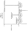
- FIG. 1 schematically illustrates a process of cancelling the lock-being-continued mode applied by application programs periodically.
- the vertical axis represents the time line, and the time passes from the top to the bottom.
- the horizontal axis represents each application program previously applied the lock mode.
- each application program is referred to as an "application.”
- Some of the applications that are forcibly terminated due to inconvenience occurring in a system are recoverable to be in an active status by automatically performing a resuming process to continue a specific operation that was being performed before the forced termination of the application.
- an image forming apparatus is installed with a facsimile application to transmit and receive facsimile (FAX) data. If the facsimile application was forcibly terminated while the image forming apparatus receiving the FAX data, the facsimile application is automatically resumed to be in the active mode to receive the FAX data that was not received by the forced termination.
- FAX facsimile
- the application is determined as being in an inactive status by the periodical check and the lock applied by the application is forcibly canceled (unlocked).
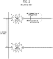
- FIG. 2 schematically illustrates a process of cancelling the lock mode applied by application when the resuming process is performed.
- an application is forcibly terminated right before the periodical check time point t2, and then the application is resumed right after the periodic check time point t2 by performing the resuming process after the forced termination.
- the lock mode applied by the application is canceled at the periodical check time point t2.
- the apparatus may shift to the power-saving mode at a timing that is not convenient for the application during or after the resuming process of the application, causing the application unable to continue the specific operation that the application is designed to complete.
- transition or shift to the power-saving mode is described as one example, but not limited thereto. Any other operation of the apparatus may be affected by the transition or shift to the power-saving mode.
- An example of the embodiments includes information processing apparatus (10) including a check unit (201, 111, 134) and a cancel unit (201, 111, 135).
- the check unit (201, 111, 134) checks whether a program is active or inactive at plural timings. The program is previously terminated while keeping prohibition of at least one operation of the information processing apparatus.
- the cancel unit (201, 111, 135) cancels the prohibition of the at least one operation of the information processing apparatus when the program is inactive continuously for a given period of time.
- the above described information processing apparatus (10) can reduce occurring of operation, which is not convenient for the program, in the information processing apparatus (10).
- FIG. 3 illustrates an example of a hardware block diagram of an image forming apparatus 10 according to the embodiment.
- the image forming apparatus 10 includes hardware resources, such as a controller 11, a scanner 12, a printer 13, a modem 14, a network interface 16, and a secure digital (SD) card slot 17.
- hardware resources such as a controller 11, a scanner 12, a printer 13, a modem 14, a network interface 16, and a secure digital (SD) card slot 17.
- SD secure digital
- the controller 11 serves as a computer in a main unit of the image forming apparatus 10. As illustrated in FIG. 3 , the controller 11 includes, for example, a central processing unit (CPU) 111, a random access memory (RAM) 112, a read only memory (ROM) 113, a hard disc drive (HDD) 114, and a non-volatile random access memory (NVRAM) 115.
- the ROM 113 stores various programs and data used by the programs.
- the RAM 112 is used as a memory area to which a program is loaded and used as a work area for executing a loaded program.
- the CPU 111 executes a program loaded to the RAM 112 to implement various functions.
- the HDD 114 stores programs and various data used by the programs.
- the NVRAM 115 stores various setting information.
- the scanner 12 is hardware (image reading device) that scans a document to obtain image data.
- the printer 13 is hardware (printing device) that forms an image on a sheet in accordance with print data.
- the modem 14 is hardware for connecting to a telephone line, which is used for transmitting and receiving image data by facsimile communication.
- the network interface 16 is hardware to connect the image forming apparatus 10 to a wired or wireless network, such as a local area network (LAN).
- the SD card slot 17 is used for reading programs stored in a SD card 80. Accordingly, in the image forming apparatus 10, not only the programs stored in the ROM 113 but also the programs stored in the SD card 80 may be loaded to the RAM 112 for execution.
- any other suitable storage medium may be used, such as a compact disk read only memory (CD-ROM) or a universal serial bus (USB) memory.
- CD-ROM compact disk read only memory
- USB universal serial bus
- the type of storage medium corresponding to the SD card 80 is not limited to a specific type.
- any other suitable hardware is used in alternative to the SD card slot 17 depending on a type of storage medium.
- the controller 11 is connected to an information processing terminal 20.
- Examples of the information processing terminal 20 employs, for example, a smartphone and a tablet terminal.
- the smartphone is a terminal device that has multiple functions, such as a calling function of mobile phone, an imaging function implemented by a camera, and a function of displaying web information like a PC.
- the tablet terminal serves as a multifunction terminal in the same way as the smartphone.
- the information processing terminal 20 serves as an operation unit of the image forming apparatus 10. More specifically, the information processing terminal 20 is connected to the controller 11 in place of a control panel conventionally mounted as an operation unit dedicated to the image forming apparatus 10. The controller 11 and the information processing terminal 20 are connected via, for example, a USB cable, short-distance wireless communication, or a communication line such as a LAN.
- FIG. 4 illustrates a hardware block diagram of the information processing terminal 20 according to the embodiment.
- the information processing terminal 20 includes, for example, a CPU 201, a memory 202, an auxiliary memory 203, a touch panel 204, a wireless communication device 205, and an integrated circuit (IC) card reader 206.
- the auxiliary memory 203 stores programs and the like installed in the information processing terminal 20.
- the memory 202 reads the program from the auxiliary memory 203 and stores the read program.
- the CPU 201 executes functions designed for the information processing terminal 20 according to the program stored in the memory 202.
- the touch panel 204 is an electronic component having both an input function and a display function, and displays information and receives an user input.
- the touch panel 204 includes, for example, a display 211 and an input device 212.
- the display 211 is a liquid crystal display (LCD) or the like, and implements the display function of the touch panel 204.
- the input device 212 is an electronic component that includes a sensor to detect an object (contact object) touching the display 211.
- the method of detecting the contact object may be any one of known methods such as an electrostatic method, a resistive film method, an optical method, and the like.
- the contact object is defined as an object that touches a contact surface (surface) of the touch panel 204.
- the object is, for example a finger of a user, a dedicated or general pen, or the like.
- the wireless communication device 205 is an electronic component such as an antenna required for establishing communication in a wireless LAN or a mobile communication network. However, in the embodiment, the information processing terminal 20 can omit the wireless communication device 205.
- the IC card reader 206 reads card identification information (ID) stored in the IC card (card ID is an example of ID identifying the card).
- ID is an example of ID identifying the card.
- each user may be provided with an IC card storing a card ID that is unique to the card, and each user may be authenticated based on the corresponding card ID.
- FIG. 5 illustrates an example of a functional block diagram of the image forming apparatus 10 according to the embodiment.
- the image forming apparatus 10 includes one or more applications 120 (e.g., applications 120a, 120b, 120c), and a system device 130.
- applications 120 e.g., applications 120a, 120b, 120c
- system device 130 Each of the above-mentioned functional units is implemented by executing one or more programs installed in the information processing terminal 20 or the controller 11 by the CPU 201 or the CPU 111.
- the application 120 is an application program that provides a user a service using the image forming apparatus 10.
- the application 120 is used as a source of requesting a lock mode and canceling the lock mode (unlocking) for various operations of the image forming apparatus 10.
- the system device 130 provides each application 120 with a common function to be used by the plurality of applications 120 (e.g., applications 120a, 120b, 120c). As illustrated in FIG. 5 , the system device 130 includes, for example, an application management unit 131, a lock management unit 132, a mode transition unit 133, an unlock target specifying unit 134, and an unlock unit 135.
- the application management unit 131 manages a life cycle of the application 120. For example, the application management unit 131 installs, uninstalls, starts (activates), and terminates (deactivates) the application 120.
- the lock management unit 132 applies the lock mode to an operation of the image forming apparatus 10 (i.e., mode transition or shift), and unlocks the lock mode.
- mode transition i.e., mode transition or shift
- power mode transition offline transition, power-off of operation unit, display-off of operation unit, system reset, display mode transition of operation unit, logout and the like may be applied with the lock mode.
- the power mode transition is defined as an operation of transitioning to a power-saving mode.
- the image forming apparatus 10 transitions to the power-saving mode at a given time, such as when a certain time elapses while the image forming apparatus 10 is not being operated.
- the application 120 requests the lock management unit 132 to disenable the power mode transition (lock the transition of power mode) to prohibit the transition of the image forming apparatus 10 to the power-saving mode. Further, the application 120 requests the lock management unit 132 to unlock the locking of power mode transition (enable the power mode transition) to cancel the prohibition of the transition to the power-saving mode of the image forming apparatus 10.
- the offline transition is defined as an operation of transitioning to an offline mode.
- the offline mode is defined as a mode in which values of setting items of the image forming apparatus 10 are changed (that is, a mode in which setting operation is performed on the image forming apparatus 10).
- various timers stop, and transition to the power-saving mode, automatic switching of the application 120 or switching of the application 120 in accordance with a user operation is prohibited.
- the application 120 requests the lock management unit 132 to lock the offline transition to prohibit the image forming apparatus 10 from transitioning to the power-saving mode. Further, the application 120 requests the lock management unit 132 to unlock the locking of the offline transition to cancel the prohibition of the transition to the offline mode of the image forming apparatus 10.
- the power-off of operation unit is defined as an operation of stopping power supply to the operation unit (information processing terminal 20).
- the application 120 requests the lock management unit 132 to lock the power-off of operation unit to prohibits the power-off of the information processing terminal 20.
- the application 120 requests the lock management unit 132 to unlock the locking of the power-off of operation unit to cancel the prohibition of the power-off of the information processing terminal 20.
- the display-off of operation unit is defined as an operation of stopping displaying on the display 211 of the operation unit (information processing terminal 20).
- the application 120 requests the lock management unit 132 to lock the display-off of operation unit to prohibit the displaying on the display 211. Further, the application 120 requests the lock management unit 132 to unlock the locking of the display-off of operation unit to cancel the prohibition of the displaying on the display 211.
- the system reset is defined as an operation of automatically switching a display screen of the information processing terminal 20 to an initial screen, and resetting setting values to initial values when a user operation is not being performed for a certain period of time.
- the setting values that were input via a screen being displayed right before the switching are reset to the initial values.
- the application 120 requests the lock management unit 132 to lock the system reset to prohibit the system reset. Further, the application 120 requests the lock management unit 132 to unlock the locking of the system reset to cancel the prohibition of the system reset.
- the display mode transition of operation unit is defined as an operation of changing a display mode of the operation unit (information processing terminal 20).
- the display mode includes, for example, three modes such as a display stop mode, a display mode, and a sleep mode.
- the application 120 requests the lock management unit 132 to lock the display mode transition of operation unit to prohibit the display mode transition of operation unit.
- the application 120 requests the lock management unit 132 to unlock the locking of the display mode transition of operation unit to cancel the prohibition of the display mode transition of operation unit.
- the logout is defined as an operation of logging out of a login user.
- the application 120 requests the lock management unit 132 to lock the logout to prohibit the logout under a condition where the logout may cause a trouble, for example, when the image forming apparatus 10 is performing a job. Further, the application 120 requests the lock management unit 132 to unlock the locking of the logout to cancel the prohibition of the logout.
- each of the above described operation may be requested by each application 120.
- the operation is prohibited. That is, if an operation is locked by the plurality of applications 120, the operation is prohibited until the locking by all of the plurality of applications 120 is unlocked.
- the mode transition unit 133 controls an operation not applied with the lock mode (i.e., controls the mode transition), for the above-described operations applicable with the lock mode.
- the mode transition unit 133 controls the mode transition.
- the unlock target specifying unit 134 checks whether each application 120 is being executed (active) at a plurality of time points to specify one or more applications 120 that has been terminated while keeping the lock mode and that is not expected to resume.
- the unlock unit 135 forcibly cancels (unlocks) the lock mode applied by the application 120 specified by the unlock target specifying unit 134.
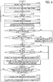
- FIG. 6 is a flowchart illustrating an example process performed by the image forming apparatus 10 according to the embodiment.
- the unlock target specifying unit 134 specifies a checking time.
- the checking time is defined as a timing to perform the sequence of S102 to S116 repeatedly.
- the checking time is specified according to a check interval that is set in advance. For example, when the check interval is set to thirty seconds, the checking time comes after thirty seconds from a current time.
- the check interval may be common to all the applications 120 or may be set differently for each of the applications 120.
- the check interval of the application 120 may be acquired from configuration information included in an installation package (archive file) of the application 120 at the time of installing the application 120. Alternatively, the check interval may be acquired from the configuration information of the application 120 when the application 120 is activated for the first time.
- FIG. 7 illustrates an example of configuration information of the application 120.
- the configuration information of the application 120 is defined in an extensible markup language (XML) format, but the format of the configuration information is not limited thereto.
- a description d1 indicates identification information (hereinafter, referred to as "application identifier") of the application 120.
- a description d2 indicates that the check interval of the application 120 is thirty seconds.
- a pre-set value (default value) may be used as the check interval.
- the pre-set value may be changeable by a user operation or a remote operation performed via a network. Further, the pre-set value may be changed by using an IC card or the like.
- the unlock target specifying unit 134 may use logical addition of the checking times based on the check intervals of the applications 120 to set a checking time for the future checking. For example, when the check interval of the application 120a is two minutes and the check interval of the application 120b is five minutes, the checking times are set at, from a current time, two minutes later, four minutes later, five minutes later, six minutes later, eight minutes later, ten minutes later, ..., and so on. In the above-described case, the checking time at two minutes later, four minutes later, six minutes later, and eight minutes later from the current time are set for the application 120a. The checking time at five minutes later from the current time is set for the check timing for the application 120b. The checking time at ten minutes later from the current time is the check timing set for both the application 120a and the application 120b.
- the unlock target specifying unit 134 waits until a next checking time comes (S102). It should be noted that when S102 is performed for the first time, the next checking time is the first checking time. When the next checking time comes, the unlock target specifying unit 134 acquires from the lock management unit 132 information indicating a current locking status of the entire system (hereinafter, referred to as locking status information) (S103).
- FIG. 8 illustrates examples of the locking status information.
- FIG. 8(1) illustrates a first example of the locking status information
- FIG. 8(2) illustrates a second example of the locking status information.
- the locking status information includes a value indicating a current status (whether each operation is locked or not, that is, prohibited or not prohibited), for each operation, to which the lock mode (prohibition) is applicable, of the image forming apparatus 10 of the embodiment.
- the value indicating the current status is LOCKED or UNLOCKED.
- LOCKED is defined as a locked mode (a mode in which the corresponding operation is locked and prohibited).
- UNLOCKED is defined as an unlocked mode (mode in which the prohibition of the corresponding operation is unlocked (canceled)).
- the power mode transition and logout are locked. In other words, the transition of the power mode (e.g., transition from the standby mode to the power-saving mode) is prohibited, and changing a login status of a currently logged-in user manually or automatically to a logout status is prohibited.
- an application identifier (e.g., "xxxxxxxxxxxxxxxxx2") of the application 120 that is a lock request source is associated with the operation having a lock status of LOCKED.
- the lock status of each operation is set LOCKED when the lock is requested from at least one of the applications 120, and the lock status of each operation is set UNLOCKED when the operation is not locked by any of the applications 120.
- the unlock target specifying unit 134 determines whether one or more operations are locked (having the lock status of LOCKED) by checking the locking status information (S104). When no operation is locked (S104: NO), the unlock target specifying unit 134 returns to S102 to wait until the next checking time, and then performs the sequence from S103 again.
- the unlock target specifying unit 134 acquires list information of the applications 120 (hereinafter, an application list), which are installed in the image forming apparatus 10, from the application management unit 131 (S105).
- FIG. 9 illustrates an example of the application list.
- the application list includes, for example, an application identifier and an operational status of each application 120 installed in the image forming apparatus 10.
- the application identifier is identification information identifying the corresponding application 120 as described above.
- any application identifier such as a data type, a length, a data format, and the like can be used.
- a Java (registered trademark) package name such as "jp.co.rrr.xxx.app 1”
- UUID universally unique identifier
- the operational status is information indicating whether the application 120 is active (executed/activated) or inactive (terminated/deactivated). Additionally, the operational status can include, for example, being installed, preparing for activation, temporary suspended, being updated, in addition to being active (executed/activated) and inactive (terminated/deactivated).
- the unlock target specifying unit 134 acquires, from the lock management unit 132, application management information of each application 120 identified by the corresponding application identifier included in the application list (S106).
- FIG. 10 illustrates an example of the application management information.
- the application management information includes, for example, an application identifier and information indicating presence or absence of a lock for each operation to which the lock is applicable.
- the application identifier is the application identifier of the application 120 corresponding to the application management information.
- the presence or absence of a lock for each operation is information indicating whether the application 120 applies a lock to each operation or not, and a value is the same as that of the lock mode information of FIG. 8 .
- the unlock target specifying unit 134 determines whether there are one or more applications 120 having the operational status of inactive and applying the lock mode to at least one operation (S107).
- the unlock target specifying unit 134 can perform the determination in S107 based on the application list ( FIG. 9 ) and the application management information ( FIG. 10 ). More specifically, the unlock target specifying unit 134 determines whether the operational status of each application is inactive based on the application list (see FIG. 9 ), and determines any one of the operations is set "LOCKED" for the application 120, which is determined as being inactive, based on the application management information (see FIG. 10 ). In the example case of FIG.
- the application list indicates that three applications 120 are installed, in which the application 120 identified by the application identifier of "xxxxxxxxxxxxxxxxx2" is inactive. Additionally, the application 120 identified by the application identifier of "xxxxxxxxxxxxxxxxxxxxx3" is also inactive. Further, in the example case of the application management information of FIG. 10 , the application 120 identified by the application identifier of "xxxxxxxxxxxxxxx2" applies the lock mode to the power mode transition. Therefore, at least the application 120 identified by the application identifier of "xxxxxxxxxxxxxxxxxx2" satisfies with the condition in S107.
- the sequence proceeds to S110.
- the unlock target specifying unit 134 determines whether the one or more applications 120 have already included in an unlock candidate list as unlock candidates (S108).
- the unlock candidate list is defined as data having a list structure for storing an application identifier and the number of inactive detection times of the application 120, which is inactive while keeping one or more operations locked.
- the unlock candidate list is vacant when the sequence of FIG. 6 is performed for the first time.
- the sequence proceeds to S110.
- the unlock target specifying unit 134 adds the application identifier and the number of inactive detection times of the application 120 to the unlock candidate list (S109), and then the sequence proceeds to S110.
- the number of inactive detection times is initialized to zero (0).
- FIG. 11 illustrates an example of the unlock candidate list.
- the unlock candidate list includes, for example, the application identifier and the number of inactive detection times for each application 120 set as the unlock candidate.
- the number of inactive detection times is the number of times continuously detecting that the application 120 is being in the inactive status when checking the application 120 while the application 120 is keeping the lock mode for one or more operations. Additionally, as long as a value of the number of inactive detection times can be counted, any application identifier, such as a data type, a length, a data format, and the like can be used. In the example case of FIG.
- the application 120 identified by an identifier of "xxxxxxxxxxxxxxxxxxxxx3" is also indicated as the unlock candidate. That is, the application 120 identified by the application identifier of "xxxxxxxxxxxxxxxxxxx2" and the application 120 identified by the identifier of "xxxxxxxxxxxxxxxxx3" are both inactive while keeping one or more operations locked.
- the unlock target specifying unit 134 determines whether there are one or more of the applications 120 being active based on the application list illustrated in FIG. 9 . When there is no application 120 being active (S110: NO), the sequence proceeds to S113. When there are one or more of the applications 120 being active (S110: YES), the unlock target specifying unit 134 determines whether the application identifier of the application 120 is included in the unlock candidate list illustrated in FIG. 11 (S111). When the application identifier of the application 120 is not included in the unlock candidate list (S111: NO), the sequence proceeds to S113.
- the unlock target specifying unit 134 deletes the application identifier of the application 120 and the number of inactive detection times from the application candidate list (S112), and the sequence proceeds to S113.
- the application 120 is the concerned application that was previously detected as being inactive while keeping one or more operations locked, and then resumed before the number of inactive detection times becomes equal to a threshold or more, which is to be described later, and the application 120 is excluded from the unlock candidates as described above.
- the unlock target specifying unit 134 adds one to the number of inactive detection times of the application 120 to be checked at a current checking time among the applications 120 included in the unlock candidate list ( FIG. 11 ).
- the application 120 to be checked at the current checking time is an application having a checking time that equals to the current checking time based on the check interval of the application 120.
- the unlock target specifying unit 134 refers to the unlock candidate list ( FIG. 11 ) to determine whether there are one or more applications 120 that have the number of inactive detection times being equal to the threshold or more (S114). That is, the unlock target specifying unit 134 determines whether the number of inactive detection times of the application 120, continuously detected for the application 120 keeping one or more operations at the lock mode, equals to the threshold or more.
- the threshold may be a value that is common to all the applications 120. Alternatively, the threshold may be a value that is set for each of the applications 120 differently. Alternatively, the threshold may be a value that is appropriately changed according to the operation.
- the sequence returns to S102 to wait until the next checking time, and then performs the sequence from S103 again.
- the unlock unit 135 unlocks all of the locked status that are applied by the application 120 (hereinafter, the application 120 may be referred to as a target application 120) (S115). That is, all of the locked status set for the operations in the application management information ( FIG. 10 ) of the target application 120 are changed to UNLOCKED.
- the lock management unit 132 also updates the locking status information illustrated in FIG. 8 as necessary. That is, in a case where there is no application 120 applying the locked status to the operations in accordance with the cancelling of the locked status, all of the lock status of the operations are updated to "UNLOCKED" in the lock mode information illustrated in FIG. 8 .
- the unlock unit 135 delates the application identifier and the number of inactive detection times of the target application 120 from the unlock candidate list (S116). Then, the unlock target specifying unit 134 returns to S102 to wait until the next checking time, and then performs the sequence from S103 again.
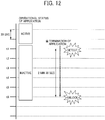
- FIG. 12 illustrates an example case where a lock is forcibly canceled according to the embodiment.
- the termination of the application 120 is detected at a checking time point t1. If the threshold of "six" is used in S114, the lock status applied by the application 120 is forcibly canceled (unlocked) at a checking time point t6. That is, when a check interval of the application 120 is thirty seconds, the lock status applied by the application 120 is canceled when the application 120 is determined to be inactive for a period of two minutes and thirty seconds.
- the lock status applied by the application 120 and detected at one checking time point is not a target to be forcibly canceled, but the lock status applied by the application 120 and continuously detected for a plurality of time points is a target to be forcibly canceled.
- the inactive status of the application 120 is being detected continuously at the plurality of time points during a given period of time, the inactive status of the application 120 is a target to be forcibly canceled. Therefore, the lock status applied by the application 120 that is detected for the termination at one checking time point and then resumed by the resuming process is excluded from the unlock target.
- the above described information processing apparatus 10 can reduce occurring of unexpected operation of the program (application 120), which is not convenient for the program, in the information processing apparatus 10.
- the check interval can be set for each application 120 differently. Accordingly, in consideration of the time required for the resuming process of each application 120, the expected tine of resuming of each application 120 is appropriately determined. For example, the example of FIG. 12 is suitable for a case when the resuming process of the application 120 takes about two minutes. If the application 120 is not reactivated when two minutes elapses from the detection of the termination, the application 120 is highly expected to fail to perform the resuming process, and the lock status applied by the application 120 is being continued.
- the embodiment as an example of the image forming apparatus 10, a multifunction peripheral having a copy function, a facsimile function, and a printer function is used.
- the embodiment is not limited to the above, and a single device having one of the above-mentioned functions, such as a copier, a facsimile, a printer, or a scanner, also may be used as the image forming apparatus 10.
- the embodiment may be applied to an apparatus other than the image forming apparatus 10 and an information processing apparatus.
- the embodiment may be applied to a projector, an electronic whiteboard, a video conference system, a general-purpose computer, or the like.
- the scanner 12 and the printer 13 in the hardware configuration of FIG.
- a projecting device is provided in place of the scanner 12 and the printer 13.
- the embodiment may be applied to each apparatus and each information processing apparatus by replacing the functions according to the corresponding characteristics of each apparatus and each information processing apparatus.
- the image forming apparatus 10 is an example of an information processing apparatus.
- the unlock target specifying unit 134 is an example of a check unit.
- the unlock unit 135 is an example of a cancel unit.
- the threshold corresponding to the number of inactive detection times is an example of the number of pre-set times.
- the present disclosure may be implemented in any convenient form, for example using dedicated hardware, or a mixture of dedicated hardware and software.
- the present disclosure may be implemented as computer software implemented by one or more networked processing apparatuses.
- the processing apparatuses can compromise any suitably programmed apparatuses such as a general purpose computer, personal digital assistant, mobile telephone (such as a WAP or 3G-compliant phone) and so on. Since the present disclosure can be implemented as software, each and every aspect of the present disclosure thus encompasses computer software implementable on a programmable device.
- the computer software can be provided to the programmable device using any conventional carrier medium (carrier means).
- the carrier medium can compromise a transient carrier medium such as an electrical, optical, microwave, acoustic or radio frequency signal carrying the computer code.
- transient medium is a TCP/IP signal carrying computer code over an IP network, such as the Internet.
- the carrier medium can also comprise a storage medium for storing processor readable code such as a floppy disk, hard disk, CD ROM, magnetic tape device or solid state memory device.
Landscapes
- Engineering & Computer Science (AREA)
- Theoretical Computer Science (AREA)
- Physics & Mathematics (AREA)
- General Engineering & Computer Science (AREA)
- General Physics & Mathematics (AREA)
- Multimedia (AREA)
- Signal Processing (AREA)
- Human Computer Interaction (AREA)
- Facsimiles In General (AREA)
- Accessory Devices And Overall Control Thereof (AREA)
- Debugging And Monitoring (AREA)
Abstract
Description
- The present disclosure relates to an information processing apparatus, a method of canceling prohibition, and carrier means such as a recording medium.
- Some of various apparatuses including an image forming apparatus have a plurality of operational modes. For example, an apparatus has the plurality of operation modes, such as a power-saving mode (energy-saving mode) and a non-power-saving mode (e.g., normal mode). The power-saving mode is defined as a mode in which the apparatus stops supplying a power to some or all of the hardware resources to save the power consumption.
- Some apparatuses implement a transition to the power-saving mode using a program-based control. In such apparatuses, when the transition to the power-saving mode occurs at a timing that is not expected by a program, abnormality may occur to the program-based control. To avoid such abnormality, some apparatuses have a mechanism of enabling any programs to apply a lock to prevent the apparatuses from transitioning to the power saving mode. Such apparatuses transitions to the power-saving mode under condition where no program applies the lock mode.
- However, there may be a case where a program, which applies a lock to the apparatus, is terminated without unlocking the lock due to an abnormal termination, a forced termination caused by inconvenience occurring in a system, or a bug related to implementation, for example. If such a lock is left, the transitioning to the power-saving state is unnecessarily prohibited, resulting in reduction of power saving efficiency.
- To cope with this situation, there is an apparatus that has a mechanism of checking whether a program that applies a lock is active or not (hereinafter, referred to as "periodical check") and forcibly canceling, or unlocking, a lock if there is such a lock (hereinafter, referred to as a "lock-being-continued mode").
-
FIG. 1 schematically illustrates a process of cancelling the lock-being-continued mode applied by application programs periodically. InFIG. 1 , the vertical axis represents the time line, and the time passes from the top to the bottom. The horizontal axis represents each application program previously applied the lock mode. Hereinafter, each application program is referred to as an "application." When the periodical check is performed at a periodical check time point t1 and a periodical check time point t2, and each application is terminated after the periodical check time point t1, the lock mode applied by each application is cancelled (unlocked) at the periodical check time point t2. - Some of the applications that are forcibly terminated due to inconvenience occurring in a system are recoverable to be in an active status by automatically performing a resuming process to continue a specific operation that was being performed before the forced termination of the application. For example, an image forming apparatus is installed with a facsimile application to transmit and receive facsimile (FAX) data. If the facsimile application was forcibly terminated while the image forming apparatus receiving the FAX data, the facsimile application is automatically resumed to be in the active mode to receive the FAX data that was not received by the forced termination.
- However, when such a resuming process of the program and the periodical check are performed at substantially the same time, the application is determined as being in an inactive status by the periodical check and the lock applied by the application is forcibly canceled (unlocked).
-
FIG. 2 schematically illustrates a process of cancelling the lock mode applied by application when the resuming process is performed. In an example case ofFIG. 2 , an application is forcibly terminated right before the periodical check time point t2, and then the application is resumed right after the periodic check time point t2 by performing the resuming process after the forced termination. In the above-described case, the lock mode applied by the application is canceled at the periodical check time point t2. - Then, the apparatus may shift to the power-saving mode at a timing that is not convenient for the application during or after the resuming process of the application, causing the application unable to continue the specific operation that the application is designed to complete.
- In the above described configuration, the transition or shift to the power-saving mode is described as one example, but not limited thereto. Any other operation of the apparatus may be affected by the transition or shift to the power-saving mode.
- An example of the embodiments includes information processing apparatus (10) including a check unit (201, 111, 134) and a cancel unit (201, 111, 135). The check unit (201, 111, 134) checks whether a program is active or inactive at plural timings. The program is previously terminated while keeping prohibition of at least one operation of the information processing apparatus. The cancel unit (201, 111, 135) cancels the prohibition of the at least one operation of the information processing apparatus when the program is inactive continuously for a given period of time.
- The above described information processing apparatus (10) can reduce occurring of operation, which is not convenient for the program, in the information processing apparatus (10).
- A more complete appreciation of the disclosure and many of the attendant advantages and features thereof can be readily obtained and understood from the following detailed description with reference to the accompanying drawings, wherein:
-
FIG. 1 illustrates a process of cancelling a lock-being-continued mode applied by application periodically in a related art; -
FIG. 2 schematically illustrates a process of cancelling the lock mode applied by application when a resuming process is performed in a related art; -
FIG. 3 illustrates an example of a hardware block diagram of an image forming apparatus according to an embodiment; -
FIG. 4 illustrates an example of a hardware block diagram of an information processing terminal according to the embodiment; -
FIG. 5 illustrates an example of a functional block diagram of the image forming apparatus according to the embodiment; -
FIG. 6 is a flowchart illustrating an example process performed by the image forming apparatus according to the embodiment; -
FIG. 7 illustrates an example of configuration information of an application according to the embedment; -
FIG. 8 illustrate examples of lock mode information according to the embodiment; -
FIG. 9 illustrates an example of an application list according to the embodiment; -
FIG. 10 illustrates an example of application management information according to the embodiment; -
FIG. 11 illustrates an example of an unlock candidate list according to the embodiment; and -
FIG. 12 illustrates an example case where a lock mode applied by application is forcibly canceled according to the embodiment. - The accompanying drawings are intended to depict example embodiments of the present disclosure and should not be interpreted to limit the scope thereof. The accompanying drawings are not to be considered as drawn to scale unless explicitly noted.
- The terminology used herein is for describing particular embodiments only and is not intended to be limiting of the present disclosure. As used herein, the singular forms "a", "an" and "the" are intended to include the plural forms as well, unless the context clearly indicates otherwise. It will be further understood that the terms "includes" and/or "including", when used in this specification, specify the presence of stated features, integers, steps, operations, elements, and/or components, but do not preclude the presence or addition of one or more other features, integers, steps, operations, elements, components, and/or groups thereof. In describing preferred embodiments illustrated in the drawings, specific terminology is employed for the sake of clarity. However, the disclosure of this patent specification is not intended to be limited to the specific terminology so selected, and it is to be understood that each specific element includes all technical equivalents that have the same function, operation in a similar manner, and achieve a similar result.
- Hereinafter, a description is given of an embodiment of this disclosure with reference to the accompanying drawings.
FIG. 3 illustrates an example of a hardware block diagram of animage forming apparatus 10 according to the embodiment. As illustrated inFIG. 3 . theimage forming apparatus 10 includes hardware resources, such as acontroller 11, ascanner 12, aprinter 13, amodem 14, anetwork interface 16, and a secure digital (SD)card slot 17. - The
controller 11 serves as a computer in a main unit of theimage forming apparatus 10. As illustrated inFIG. 3 , thecontroller 11 includes, for example, a central processing unit (CPU) 111, a random access memory (RAM) 112, a read only memory (ROM) 113, a hard disc drive (HDD) 114, and a non-volatile random access memory (NVRAM) 115. TheROM 113 stores various programs and data used by the programs. TheRAM 112 is used as a memory area to which a program is loaded and used as a work area for executing a loaded program. TheCPU 111 executes a program loaded to theRAM 112 to implement various functions. TheHDD 114 stores programs and various data used by the programs. TheNVRAM 115 stores various setting information. - The
scanner 12 is hardware (image reading device) that scans a document to obtain image data. Theprinter 13 is hardware (printing device) that forms an image on a sheet in accordance with print data. Themodem 14 is hardware for connecting to a telephone line, which is used for transmitting and receiving image data by facsimile communication. Thenetwork interface 16 is hardware to connect theimage forming apparatus 10 to a wired or wireless network, such as a local area network (LAN). TheSD card slot 17 is used for reading programs stored in aSD card 80. Accordingly, in theimage forming apparatus 10, not only the programs stored in theROM 113 but also the programs stored in theSD card 80 may be loaded to theRAM 112 for execution. In addition or in alternative to theSD card 80, any other suitable storage medium may be used, such as a compact disk read only memory (CD-ROM) or a universal serial bus (USB) memory. In other words, the type of storage medium corresponding to theSD card 80 is not limited to a specific type. In this case, any other suitable hardware is used in alternative to theSD card slot 17 depending on a type of storage medium. - The
controller 11 is connected to aninformation processing terminal 20. Examples of theinformation processing terminal 20 employs, for example, a smartphone and a tablet terminal. The smartphone is a terminal device that has multiple functions, such as a calling function of mobile phone, an imaging function implemented by a camera, and a function of displaying web information like a PC. The tablet terminal serves as a multifunction terminal in the same way as the smartphone. - In the embodiment, the
information processing terminal 20 serves as an operation unit of theimage forming apparatus 10. More specifically, theinformation processing terminal 20 is connected to thecontroller 11 in place of a control panel conventionally mounted as an operation unit dedicated to theimage forming apparatus 10. Thecontroller 11 and theinformation processing terminal 20 are connected via, for example, a USB cable, short-distance wireless communication, or a communication line such as a LAN. -
FIG. 4 illustrates a hardware block diagram of theinformation processing terminal 20 according to the embodiment. As illustrated inFIG. 4 , theinformation processing terminal 20 includes, for example, aCPU 201, amemory 202, anauxiliary memory 203, atouch panel 204, awireless communication device 205, and an integrated circuit (IC)card reader 206. - The
auxiliary memory 203 stores programs and the like installed in theinformation processing terminal 20. In response to an instruction to activate a program, thememory 202 reads the program from theauxiliary memory 203 and stores the read program. TheCPU 201 executes functions designed for theinformation processing terminal 20 according to the program stored in thememory 202. - The
touch panel 204 is an electronic component having both an input function and a display function, and displays information and receives an user input. Thetouch panel 204 includes, for example, adisplay 211 and aninput device 212. - The
display 211 is a liquid crystal display (LCD) or the like, and implements the display function of thetouch panel 204. Theinput device 212 is an electronic component that includes a sensor to detect an object (contact object) touching thedisplay 211. The method of detecting the contact object may be any one of known methods such as an electrostatic method, a resistive film method, an optical method, and the like. Hereinafter, the contact object is defined as an object that touches a contact surface (surface) of thetouch panel 204. The object is, for example a finger of a user, a dedicated or general pen, or the like. - The
wireless communication device 205 is an electronic component such as an antenna required for establishing communication in a wireless LAN or a mobile communication network. However, in the embodiment, theinformation processing terminal 20 can omit thewireless communication device 205. - The
IC card reader 206 reads card identification information (ID) stored in the IC card (card ID is an example of ID identifying the card). For example, each user may be provided with an IC card storing a card ID that is unique to the card, and each user may be authenticated based on the corresponding card ID. -
FIG. 5 illustrates an example of a functional block diagram of theimage forming apparatus 10 according to the embodiment. As illustrated inFIG. 5 , theimage forming apparatus 10 includes one or more applications 120 (e.g.,applications system device 130. Each of the above-mentioned functional units is implemented by executing one or more programs installed in theinformation processing terminal 20 or thecontroller 11 by theCPU 201 or theCPU 111. - The
application 120 is an application program that provides a user a service using theimage forming apparatus 10. In the embodiment, theapplication 120 is used as a source of requesting a lock mode and canceling the lock mode (unlocking) for various operations of theimage forming apparatus 10. - The
system device 130 provides eachapplication 120 with a common function to be used by the plurality of applications 120 (e.g.,applications FIG. 5 , thesystem device 130 includes, for example, anapplication management unit 131, alock management unit 132, amode transition unit 133, an unlocktarget specifying unit 134, and anunlock unit 135. - The
application management unit 131 manages a life cycle of theapplication 120. For example, theapplication management unit 131 installs, uninstalls, starts (activates), and terminates (deactivates) theapplication 120. - In response to a request from the
application 120, thelock management unit 132 applies the lock mode to an operation of the image forming apparatus 10 (i.e., mode transition or shift), and unlocks the lock mode. For example, power mode transition, offline transition, power-off of operation unit, display-off of operation unit, system reset, display mode transition of operation unit, logout and the like may be applied with the lock mode. - The power mode transition is defined as an operation of transitioning to a power-saving mode. For example, the
image forming apparatus 10 transitions to the power-saving mode at a given time, such as when a certain time elapses while theimage forming apparatus 10 is not being operated. Theapplication 120 requests thelock management unit 132 to disenable the power mode transition (lock the transition of power mode) to prohibit the transition of theimage forming apparatus 10 to the power-saving mode. Further, theapplication 120 requests thelock management unit 132 to unlock the locking of power mode transition (enable the power mode transition) to cancel the prohibition of the transition to the power-saving mode of theimage forming apparatus 10. - The offline transition is defined as an operation of transitioning to an offline mode. The offline mode is defined as a mode in which values of setting items of the
image forming apparatus 10 are changed (that is, a mode in which setting operation is performed on the image forming apparatus 10). In the offline mode, various timers stop, and transition to the power-saving mode, automatic switching of theapplication 120 or switching of theapplication 120 in accordance with a user operation is prohibited. Theapplication 120 requests thelock management unit 132 to lock the offline transition to prohibit theimage forming apparatus 10 from transitioning to the power-saving mode. Further, theapplication 120 requests thelock management unit 132 to unlock the locking of the offline transition to cancel the prohibition of the transition to the offline mode of theimage forming apparatus 10. - The power-off of operation unit is defined as an operation of stopping power supply to the operation unit (information processing terminal 20). The
application 120 requests thelock management unit 132 to lock the power-off of operation unit to prohibits the power-off of theinformation processing terminal 20. Theapplication 120 requests thelock management unit 132 to unlock the locking of the power-off of operation unit to cancel the prohibition of the power-off of theinformation processing terminal 20. - The display-off of operation unit is defined as an operation of stopping displaying on the
display 211 of the operation unit (information processing terminal 20). Theapplication 120 requests thelock management unit 132 to lock the display-off of operation unit to prohibit the displaying on thedisplay 211. Further, theapplication 120 requests thelock management unit 132 to unlock the locking of the display-off of operation unit to cancel the prohibition of the displaying on thedisplay 211. - The system reset is defined as an operation of automatically switching a display screen of the
information processing terminal 20 to an initial screen, and resetting setting values to initial values when a user operation is not being performed for a certain period of time. In resetting the setting values, the setting values that were input via a screen being displayed right before the switching, are reset to the initial values. Theapplication 120 requests thelock management unit 132 to lock the system reset to prohibit the system reset. Further, theapplication 120 requests thelock management unit 132 to unlock the locking of the system reset to cancel the prohibition of the system reset. - The display mode transition of operation unit is defined as an operation of changing a display mode of the operation unit (information processing terminal 20). The display mode includes, for example, three modes such as a display stop mode, a display mode, and a sleep mode. The
application 120 requests thelock management unit 132 to lock the display mode transition of operation unit to prohibit the display mode transition of operation unit. In addition, theapplication 120 requests thelock management unit 132 to unlock the locking of the display mode transition of operation unit to cancel the prohibition of the display mode transition of operation unit. - The logout is defined as an operation of logging out of a login user. The
application 120 requests thelock management unit 132 to lock the logout to prohibit the logout under a condition where the logout may cause a trouble, for example, when theimage forming apparatus 10 is performing a job. Further, theapplication 120 requests thelock management unit 132 to unlock the locking of the logout to cancel the prohibition of the logout. - The locking of each of the above described operation may be requested by each
application 120. When an operation is locked by any one of theapplications 120, the operation is prohibited. That is, if an operation is locked by the plurality ofapplications 120, the operation is prohibited until the locking by all of the plurality ofapplications 120 is unlocked. - The
mode transition unit 133 controls an operation not applied with the lock mode (i.e., controls the mode transition), for the above-described operations applicable with the lock mode. Themode transition unit 133 controls the mode transition. - The unlock
target specifying unit 134 checks whether eachapplication 120 is being executed (active) at a plurality of time points to specify one ormore applications 120 that has been terminated while keeping the lock mode and that is not expected to resume. - The
unlock unit 135 forcibly cancels (unlocks) the lock mode applied by theapplication 120 specified by the unlocktarget specifying unit 134. - Hereinafter, a description is given of a process performed by the
image forming apparatus 10.FIG. 6 is a flowchart illustrating an example process performed by theimage forming apparatus 10 according to the embodiment. - In S101, the unlock
target specifying unit 134 specifies a checking time. The checking time is defined as a timing to perform the sequence of S102 to S116 repeatedly. The checking time is specified according to a check interval that is set in advance. For example, when the check interval is set to thirty seconds, the checking time comes after thirty seconds from a current time. The check interval may be common to all theapplications 120 or may be set differently for each of theapplications 120. When the check interval is settable for eachapplication 120, for example, the check interval of theapplication 120 may be acquired from configuration information included in an installation package (archive file) of theapplication 120 at the time of installing theapplication 120. Alternatively, the check interval may be acquired from the configuration information of theapplication 120 when theapplication 120 is activated for the first time. -
FIG. 7 illustrates an example of configuration information of theapplication 120. In the example ofFIG. 7 , the configuration information of theapplication 120 is defined in an extensible markup language (XML) format, but the format of the configuration information is not limited thereto. InFIG. 7 , a description d1 indicates identification information (hereinafter, referred to as "application identifier") of theapplication 120. A description d2 indicates that the check interval of theapplication 120 is thirty seconds. - For the
application 120 whose configuration information is not acquirable, a pre-set value (default value) may be used as the check interval. The pre-set value may be changeable by a user operation or a remote operation performed via a network. Further, the pre-set value may be changed by using an IC card or the like. - When the check intervals of the
applications 120 differs from each other, the unlocktarget specifying unit 134 may use logical addition of the checking times based on the check intervals of theapplications 120 to set a checking time for the future checking. For example, when the check interval of theapplication 120a is two minutes and the check interval of theapplication 120b is five minutes, the checking times are set at, from a current time, two minutes later, four minutes later, five minutes later, six minutes later, eight minutes later, ten minutes later, ..., and so on. In the above-described case, the checking time at two minutes later, four minutes later, six minutes later, and eight minutes later from the current time are set for theapplication 120a. The checking time at five minutes later from the current time is set for the check timing for theapplication 120b. The checking time at ten minutes later from the current time is the check timing set for both theapplication 120a and theapplication 120b. - Subsequently, the unlock
target specifying unit 134 waits until a next checking time comes (S102). It should be noted that when S102 is performed for the first time, the next checking time is the first checking time. When the next checking time comes, the unlocktarget specifying unit 134 acquires from thelock management unit 132 information indicating a current locking status of the entire system (hereinafter, referred to as locking status information) (S103). -
FIG. 8 illustrates examples of the locking status information.FIG. 8(1) illustrates a first example of the locking status information, andFIG. 8(2) illustrates a second example of the locking status information. - The locking status information includes a value indicating a current status (whether each operation is locked or not, that is, prohibited or not prohibited), for each operation, to which the lock mode (prohibition) is applicable, of the
image forming apparatus 10 of the embodiment. The value indicating the current status is LOCKED or UNLOCKED. LOCKED is defined as a locked mode (a mode in which the corresponding operation is locked and prohibited). UNLOCKED is defined as an unlocked mode (mode in which the prohibition of the corresponding operation is unlocked (canceled)). In the example ofFIG. 8(1) , the power mode transition and logout are locked. In other words, the transition of the power mode (e.g., transition from the standby mode to the power-saving mode) is prohibited, and changing a login status of a currently logged-in user manually or automatically to a logout status is prohibited. - In the example of
FIG. 8(2) , an application identifier (e.g., "xxxxxxxxxxxxxxxxx2") of theapplication 120 that is a lock request source is associated with the operation having a lock status of LOCKED. - The lock status of each operation is set LOCKED when the lock is requested from at least one of the
applications 120, and the lock status of each operation is set UNLOCKED when the operation is not locked by any of theapplications 120. - Then, the unlock
target specifying unit 134 determines whether one or more operations are locked (having the lock status of LOCKED) by checking the locking status information (S104). When no operation is locked (S104: NO), the unlocktarget specifying unit 134 returns to S102 to wait until the next checking time, and then performs the sequence from S103 again. - When one or more operations are locked (S104: YES), the unlock
target specifying unit 134 acquires list information of the applications 120 (hereinafter, an application list), which are installed in theimage forming apparatus 10, from the application management unit 131 (S105). -
FIG. 9 illustrates an example of the application list. As illustrated inFIG. 9 , the application list includes, for example, an application identifier and an operational status of eachapplication 120 installed in theimage forming apparatus 10. - The application identifier is identification information identifying the
corresponding application 120 as described above. As long as a value of the application identifier identifies thecorresponding application 120, any application identifier, such as a data type, a length, a data format, and the like can be used. For example, a Java (registered trademark) package name, such as "jp.co.rrr.xxx.app 1" or a universally unique identifier (UUID), such as "350e6402-a73b-41d2-a716-146625340000" may be used as the application identifier. - The operational status is information indicating whether the
application 120 is active (executed/activated) or inactive (terminated/deactivated). Additionally, the operational status can include, for example, being installed, preparing for activation, temporary suspended, being updated, in addition to being active (executed/activated) and inactive (terminated/deactivated). - Then, the unlock
target specifying unit 134 acquires, from thelock management unit 132, application management information of eachapplication 120 identified by the corresponding application identifier included in the application list (S106). -
FIG. 10 illustrates an example of the application management information. As illustrated inFIG. 10 , the application management information includes, for example, an application identifier and information indicating presence or absence of a lock for each operation to which the lock is applicable. - The application identifier is the application identifier of the
application 120 corresponding to the application management information. The presence or absence of a lock for each operation is information indicating whether theapplication 120 applies a lock to each operation or not, and a value is the same as that of the lock mode information ofFIG. 8 . - Then, the unlock
target specifying unit 134 determines whether there are one ormore applications 120 having the operational status of inactive and applying the lock mode to at least one operation (S107). The unlocktarget specifying unit 134 can perform the determination in S107 based on the application list (FIG. 9 ) and the application management information (FIG. 10 ). More specifically, the unlocktarget specifying unit 134 determines whether the operational status of each application is inactive based on the application list (seeFIG. 9 ), and determines any one of the operations is set "LOCKED" for theapplication 120, which is determined as being inactive, based on the application management information (seeFIG. 10 ). In the example case ofFIG. 9 , the application list indicates that threeapplications 120 are installed, in which theapplication 120 identified by the application identifier of "xxxxxxxxxxxxxxxxx2" is inactive. Additionally, theapplication 120 identified by the application identifier of "xxxxxxxxxxxxxxxxx3" is also inactive. Further, in the example case of the application management information ofFIG. 10 , theapplication 120 identified by the application identifier of "xxxxxxxxxxxxxxxxx2" applies the lock mode to the power mode transition. Therefore, at least theapplication 120 identified by the application identifier of "xxxxxxxxxxxxxxxxx2" satisfies with the condition in S107. - When there is no
application 120 that satisfies with the above-mentioned condition (S107: NO), the sequence proceeds to S110. When there are one ormore applications 120 that satisfy the above-mentioned condition (S107: YES), the unlocktarget specifying unit 134 determines whether the one ormore applications 120 have already included in an unlock candidate list as unlock candidates (S108). The unlock candidate list is defined as data having a list structure for storing an application identifier and the number of inactive detection times of theapplication 120, which is inactive while keeping one or more operations locked. The unlock candidate list is vacant when the sequence ofFIG. 6 is performed for the first time. - If the application identifier of the
application 120 is already stored in the unlock candidate list (S108: YES), the sequence proceeds to S110. On the other hand, if the application identifier of theapplication 120 is not included in the unlock candidate list (S108: NO), the unlocktarget specifying unit 134 adds the application identifier and the number of inactive detection times of theapplication 120 to the unlock candidate list (S109), and then the sequence proceeds to S110. When theapplication 120 is added to the unlock candidate list (S109), the number of inactive detection times is initialized to zero (0). -
FIG. 11 illustrates an example of the unlock candidate list. As illustrated inFIG. 11 , the unlock candidate list includes, for example, the application identifier and the number of inactive detection times for eachapplication 120 set as the unlock candidate. The number of inactive detection times is the number of times continuously detecting that theapplication 120 is being in the inactive status when checking theapplication 120 while theapplication 120 is keeping the lock mode for one or more operations. Additionally, as long as a value of the number of inactive detection times can be counted, any application identifier, such as a data type, a length, a data format, and the like can be used. In the example case ofFIG. 11 , in addition to theapplication 120 identified by the application identifier of "xxxxxxxxxxxxxxxxx2," theapplication 120 identified by an identifier of "xxxxxxxxxxxxxxxxx3" is also indicated as the unlock candidate. That is, theapplication 120 identified by the application identifier of "xxxxxxxxxxxxxxxxx2" and theapplication 120 identified by the identifier of "xxxxxxxxxxxxxxxxx3" are both inactive while keeping one or more operations locked. - In S110, the unlock
target specifying unit 134 determines whether there are one or more of theapplications 120 being active based on the application list illustrated inFIG. 9 . When there is noapplication 120 being active (S110: NO), the sequence proceeds to S113. When there are one or more of theapplications 120 being active (S110: YES), the unlocktarget specifying unit 134 determines whether the application identifier of theapplication 120 is included in the unlock candidate list illustrated inFIG. 11 (S111). When the application identifier of theapplication 120 is not included in the unlock candidate list (S111: NO), the sequence proceeds to S113. If the application identifier of theapplication 120 is included in the unlock candidate list (S111: YES), the unlocktarget specifying unit 134 deletes the application identifier of theapplication 120 and the number of inactive detection times from the application candidate list (S112), and the sequence proceeds to S113. Theapplication 120 is the concerned application that was previously detected as being inactive while keeping one or more operations locked, and then resumed before the number of inactive detection times becomes equal to a threshold or more, which is to be described later, and theapplication 120 is excluded from the unlock candidates as described above. - In S113, the unlock
target specifying unit 134 adds one to the number of inactive detection times of theapplication 120 to be checked at a current checking time among theapplications 120 included in the unlock candidate list (FIG. 11 ). Theapplication 120 to be checked at the current checking time is an application having a checking time that equals to the current checking time based on the check interval of theapplication 120. - Then, the unlock
target specifying unit 134 refers to the unlock candidate list (FIG. 11 ) to determine whether there are one ormore applications 120 that have the number of inactive detection times being equal to the threshold or more (S114). That is, the unlocktarget specifying unit 134 determines whether the number of inactive detection times of theapplication 120, continuously detected for theapplication 120 keeping one or more operations at the lock mode, equals to the threshold or more. The threshold may be a value that is common to all theapplications 120. Alternatively, the threshold may be a value that is set for each of theapplications 120 differently. Alternatively, the threshold may be a value that is appropriately changed according to the operation. - When no
application 120 satisfies the above-mentioned condition (S114: NO), the sequence returns to S102 to wait until the next checking time, and then performs the sequence from S103 again. When one ormore applications 120 satisfy the above-mentioned condition (S114: YES), theunlock unit 135 unlocks all of the locked status that are applied by the application 120 (hereinafter, theapplication 120 may be referred to as a target application 120) (S115). That is, all of the locked status set for the operations in the application management information (FIG. 10 ) of thetarget application 120 are changed to UNLOCKED. In response to the cancelling of the lock status, thelock management unit 132 also updates the locking status information illustrated inFIG. 8 as necessary. That is, in a case where there is noapplication 120 applying the locked status to the operations in accordance with the cancelling of the locked status, all of the lock status of the operations are updated to "UNLOCKED" in the lock mode information illustrated inFIG. 8 . - Then, the
unlock unit 135 delates the application identifier and the number of inactive detection times of thetarget application 120 from the unlock candidate list (S116). Then, the unlocktarget specifying unit 134 returns to S102 to wait until the next checking time, and then performs the sequence from S103 again. - The lock status is forcibly canceled in a case illustrated in
FIG. 12 using the sequence ofFIG. 6 .FIG. 12 illustrates an example case where a lock is forcibly canceled according to the embodiment. - In
FIG. 12 , the termination of theapplication 120 is detected at a checking time point t1. If the threshold of "six" is used in S114, the lock status applied by theapplication 120 is forcibly canceled (unlocked) at a checking time point t6. That is, when a check interval of theapplication 120 is thirty seconds, the lock status applied by theapplication 120 is canceled when theapplication 120 is determined to be inactive for a period of two minutes and thirty seconds. - As to the above described embodiment, the lock status applied by the
application 120 and detected at one checking time point is not a target to be forcibly canceled, but the lock status applied by theapplication 120 and continuously detected for a plurality of time points is a target to be forcibly canceled. In other words, if the inactive status of theapplication 120 is being detected continuously at the plurality of time points during a given period of time, the inactive status of theapplication 120 is a target to be forcibly canceled. Therefore, the lock status applied by theapplication 120 that is detected for the termination at one checking time point and then resumed by the resuming process is excluded from the unlock target. As a result, the above describedinformation processing apparatus 10 can reduce occurring of unexpected operation of the program (application 120), which is not convenient for the program, in theinformation processing apparatus 10. - Furthermore, in the embodiment, the check interval can be set for each
application 120 differently. Accordingly, in consideration of the time required for the resuming process of eachapplication 120, the expected tine of resuming of eachapplication 120 is appropriately determined. For example, the example ofFIG. 12 is suitable for a case when the resuming process of theapplication 120 takes about two minutes. If theapplication 120 is not reactivated when two minutes elapses from the detection of the termination, theapplication 120 is highly expected to fail to perform the resuming process, and the lock status applied by theapplication 120 is being continued. - In the description of the embodiment, as an example of the
image forming apparatus 10, a multifunction peripheral having a copy function, a facsimile function, and a printer function is used. However, the embodiment is not limited to the above, and a single device having one of the above-mentioned functions, such as a copier, a facsimile, a printer, or a scanner, also may be used as theimage forming apparatus 10. Moreover, the embodiment may be applied to an apparatus other than theimage forming apparatus 10 and an information processing apparatus. For example, the embodiment may be applied to a projector, an electronic whiteboard, a video conference system, a general-purpose computer, or the like. In a case of a projector, thescanner 12 and theprinter 13 in the hardware configuration ofFIG. 3 are not necessary. In the case of a projector, a projecting device is provided in place of thescanner 12 and theprinter 13. As described above, the embodiment may be applied to each apparatus and each information processing apparatus by replacing the functions according to the corresponding characteristics of each apparatus and each information processing apparatus. - In the above embodiment, the
image forming apparatus 10 is an example of an information processing apparatus. The unlocktarget specifying unit 134 is an example of a check unit. Theunlock unit 135 is an example of a cancel unit. The threshold corresponding to the number of inactive detection times is an example of the number of pre-set times. - Any one of the above-described operations may be performed in various other ways, for example, in an order different from the one described above.
- The present disclosure may be implemented in any convenient form, for example using dedicated hardware, or a mixture of dedicated hardware and software. The present disclosure may be implemented as computer software implemented by one or more networked processing apparatuses. The processing apparatuses can compromise any suitably programmed apparatuses such as a general purpose computer, personal digital assistant, mobile telephone (such as a WAP or 3G-compliant phone) and so on. Since the present disclosure can be implemented as software, each and every aspect of the present disclosure thus encompasses computer software implementable on a programmable device. The computer software can be provided to the programmable device using any conventional carrier medium (carrier means). The carrier medium can compromise a transient carrier medium such as an electrical, optical, microwave, acoustic or radio frequency signal carrying the computer code. An example of such a transient medium is a TCP/IP signal carrying computer code over an IP network, such as the Internet. The carrier medium can also comprise a storage medium for storing processor readable code such as a floppy disk, hard disk, CD ROM, magnetic tape device or solid state memory device.
- Although the embodiments of the disclosure have been described and illustrated above, such description is not intended to limit the disclosure to the illustrated embodiments. Numerous additional modifications and variations are possible in light of the above teachings. It is therefore to be understood that within the scope of the appended claims, the embodiments may be practiced otherwise than as specifically described herein. For example, elements and/or features of different illustrative embodiments may be combined with each other and/or substituted for each other within the scope of this disclosure and appended claims.
Claims (11)
- An information processing apparatus (10), comprising:a check unit (201, 111, 134) configured to check whether a program, installed in the information processing apparatus (10), is returned to an active status at a plurality of time points after the program is set to an inactive status while keeping prohibition of an operation of the information processing apparatus; anda cancel unit (201, 111, 135) configured to cancel the prohibition of the operation of the information processing apparatus when the program is being in the inactive status for a given period of time.
- The information processing apparatus (10) of claim 1,
wherein the cancel unit (201, 111, 135) cancels the prohibition when the program is being continuously detected in the inactive status for a given number of times in checking the program at the plurality of time points. - The information processing apparatus (10) of any one of claim 1 and claim 2,
wherein when an execution of the program is detected before detecting that the program is being continuously detected in the inactive status for the given period of time, the cancel unit (201, 111, 135) keeps the prohibition. - The information processing apparatus (10) of any one of claim 1 to claim 3,
wherein the program includes a plurality of programs,
wherein when the plurality of programs is being in the inactive status while keeping the prohibition of the operation of the information processing apparatus, the check unit (201, 111, 134) checks whether each one of the plurality of programs is in the active status at the plurality of time points, which are set for each one of the plurality of programs differently. - The information processing apparatus (10) of any one of claim 1 to claim 4, wherein the operation includes a transition to an energy saving mode.
- A method of canceling prohibition, comprising:checking (S110) whether a program, installed in an information processing apparatus, is returned to an active status at a plurality of time points after the program is set to an inactive status while keeping prohibition of an operation of the information processing apparatus; andcanceling (S115) the prohibition of the operation of the information processing apparatus when the program is being in the inactive status for a given period of time.
- The method of canceling prohibition of claim 6, further comprising
canceling (S115) the prohibition when the program is being continuously detected in the inactive status for a given number of times when checking the program at the plurality of time points. - The method of canceling prohibition of any one of claim 6 and claim 7, further comprising
keeping (S114) the prohibition when an execution of the program is detected before detecting that the program is being continuously detected in the inactive status for the given period of time. - The method of canceling prohibition of any one of claim 6 to claim 8,
wherein the program includes a plurality of programs,
wherein when the plurality of programs is being in the inactive status while keeping the prohibition of the operation of the information processing apparatus, the checking checks (110) whether each one of the plurality of programs is in the active status at the plurality of time points, which are set for each one of the plurality of programs differently. - The method of canceling prohibition of any one of claim 6 to claim 9,
wherein the operation includes a transition to an energy saving mode. - A carrier means carrying a computer readable code for controlling a computer to carry out the method of any one of claims 6 to claim 10.
Applications Claiming Priority (1)
| Application Number | Priority Date | Filing Date | Title |
|---|---|---|---|
| JP2017121617A JP6911566B2 (en) | 2017-06-21 | 2017-06-21 | Information processing device, restriction release method and restriction release program |
Publications (2)
| Publication Number | Publication Date |
|---|---|
| EP3418859A1 true EP3418859A1 (en) | 2018-12-26 |
| EP3418859B1 EP3418859B1 (en) | 2022-08-03 |
Family
ID=62837574
Family Applications (1)
| Application Number | Title | Priority Date | Filing Date |
|---|---|---|---|
| EP18178295.4A Active EP3418859B1 (en) | 2017-06-21 | 2018-06-18 | Information processing apparatus, method of canceling prohibition, and carrier means |
Country Status (3)
| Country | Link |
|---|---|
| US (1) | US10491773B2 (en) |
| EP (1) | EP3418859B1 (en) |
| JP (1) | JP6911566B2 (en) |
Citations (3)
| Publication number | Priority date | Publication date | Assignee | Title |
|---|---|---|---|---|
| WO2015126647A1 (en) * | 2014-02-20 | 2015-08-27 | Qualcomm Incorporated | Wake lock management through application monitoring |
| US9501382B2 (en) * | 2013-06-25 | 2016-11-22 | Purdue Research Foundation | Systems and methods of detecting power bugs |
| CN106502687A (en) * | 2016-10-24 | 2017-03-15 | 深圳市金立通信设备有限公司 | A kind of method and terminal for entering resting state |
Family Cites Families (36)
| Publication number | Priority date | Publication date | Assignee | Title |
|---|---|---|---|---|
| US6499031B1 (en) * | 1999-07-26 | 2002-12-24 | Microsoft Corporation | Systems and methods for using locks with computer resources |
| US7103666B2 (en) * | 2001-01-12 | 2006-09-05 | Siemens Medical Solutions Health Services Corporation | System and user interface supporting concurrent application operation and interoperability |
| JP3798353B2 (en) | 2002-09-20 | 2006-07-19 | 株式会社リコー | Electronic equipment |
| US7689708B1 (en) * | 2002-10-28 | 2010-03-30 | Netapp, Inc. | Apparatus to flow control frames in a networked storage virtualization using multiple streaming protocols |
| GB0308991D0 (en) * | 2003-04-17 | 2003-05-28 | Psion Digital Ltd | A data access replication or communication system comprising a distributed software application |
| US8432562B2 (en) | 2004-02-17 | 2013-04-30 | Ricoh Company, Ltd. | Image processing apparatus, method, program, and computer readable recording medium for controlling operation switching and displaying at occurrence of error conditions |
| JP2006222569A (en) | 2005-02-08 | 2006-08-24 | Ricoh Co Ltd | Image forming apparatus, information processing method, information processing program, and recording medium |
| JP2007152824A (en) | 2005-12-07 | 2007-06-21 | Ricoh Co Ltd | Image forming apparatus |
| KR100714710B1 (en) * | 2006-02-22 | 2007-05-04 | 삼성전자주식회사 | Apparatus and method for forcibly terminating a thread blocked by an I / O operation |
| JP4916262B2 (en) | 2006-09-13 | 2012-04-11 | 株式会社リコー | Image forming apparatus, program, and transition period setting method |
| US8117616B2 (en) * | 2007-01-09 | 2012-02-14 | International Business Machines Corporation | Preventing deadlocks |
| US8020166B2 (en) * | 2007-01-25 | 2011-09-13 | Hewlett-Packard Development Company, L.P. | Dynamically controlling the number of busy waiters in a synchronization object |
| JP5121442B2 (en) | 2007-02-14 | 2013-01-16 | 株式会社リコー | Information processing apparatus, information processing method, and program |
| US20080195688A1 (en) | 2007-02-14 | 2008-08-14 | Hideyuki Watanabe | Information processing apparatus, information processing method, and computer program product |
| JP4879785B2 (en) | 2007-03-19 | 2012-02-22 | 株式会社リコー | Information processing apparatus, information processing method, and information processing system |
| US8584138B2 (en) * | 2007-07-30 | 2013-11-12 | Hewlett-Packard Development Company, L.P. | Direct switching of software threads by selectively bypassing run queue based on selection criteria |
| US8245236B2 (en) * | 2008-02-27 | 2012-08-14 | International Business Machines Corporation | Lock based moving of threads in a shared processor partitioning environment |
| US8131983B2 (en) * | 2008-04-28 | 2012-03-06 | International Business Machines Corporation | Method, apparatus and article of manufacture for timeout waits on locks |
| JP5218003B2 (en) | 2008-12-12 | 2013-06-26 | 株式会社リコー | Image forming apparatus, authentication method, and program |
| JP5476729B2 (en) | 2009-02-12 | 2014-04-23 | 株式会社リコー | Image forming apparatus, IC card user validity checking method and program |
| US8464221B2 (en) * | 2009-06-16 | 2013-06-11 | Microsoft Corporation | Visualization tool for system tracing infrastructure events |
| US8510738B2 (en) * | 2009-08-20 | 2013-08-13 | Microsoft Corporation | Preventing unnecessary context switching by employing an indicator associated with a lock on a resource |
| JP5581863B2 (en) | 2010-07-12 | 2014-09-03 | 株式会社リコー | Image forming apparatus and authentication system. Image forming apparatus control method and control program |
| JP5358532B2 (en) | 2010-07-30 | 2013-12-04 | 京セラドキュメントソリューションズ株式会社 | Image forming apparatus |
| US8775837B2 (en) * | 2011-08-19 | 2014-07-08 | Oracle International Corporation | System and method for enabling turbo mode in a processor |
| US8966494B2 (en) * | 2012-03-16 | 2015-02-24 | Arm Limited | Apparatus and method for processing threads requiring resources |
| US9201693B2 (en) * | 2012-09-04 | 2015-12-01 | Microsoft Technology Licensing, Llc | Quota-based resource management |
| JP6393988B2 (en) | 2013-02-28 | 2018-09-26 | 株式会社リコー | Apparatus, information processing system, control method, program, and storage medium |
| US9229522B1 (en) * | 2013-08-27 | 2016-01-05 | Symantec Corporation | Mobile battery performance by identifying apps that disproportionally run background tasks that prevent mobile devices from sleeping |
| JP6176020B2 (en) | 2013-09-17 | 2017-08-09 | 株式会社リコー | Apparatus, information processing system, information processing method, information processing program, and storage medium storing information processing program |
| JP6561501B2 (en) | 2015-03-10 | 2019-08-21 | 株式会社リコー | Apparatus, authentication system, authentication processing method, authentication processing program, and storage medium |
| JP6488799B2 (en) | 2015-03-20 | 2019-03-27 | 株式会社リコー | Apparatus, information processing system, information processing method, and information processing program |
| US10546112B2 (en) | 2015-08-17 | 2020-01-28 | Ricoh Company, Ltd. | Apparatus, authentication process method, and computer program product |
| JP6700815B2 (en) * | 2016-01-29 | 2020-05-27 | キヤノン株式会社 | License management system, client device, application program |
| US10423464B2 (en) * | 2016-09-30 | 2019-09-24 | Hewlett Packard Enterprise Patent Development LP | Persistent ticket operation |
| JP6859654B2 (en) | 2016-10-11 | 2021-04-14 | 株式会社リコー | Equipment, information processing systems, information processing methods and information processing programs |
-
2017
- 2017-06-21 JP JP2017121617A patent/JP6911566B2/en active Active
-
2018
- 2018-06-14 US US16/008,308 patent/US10491773B2/en active Active
- 2018-06-18 EP EP18178295.4A patent/EP3418859B1/en active Active
Patent Citations (3)
| Publication number | Priority date | Publication date | Assignee | Title |
|---|---|---|---|---|
| US9501382B2 (en) * | 2013-06-25 | 2016-11-22 | Purdue Research Foundation | Systems and methods of detecting power bugs |
| WO2015126647A1 (en) * | 2014-02-20 | 2015-08-27 | Qualcomm Incorporated | Wake lock management through application monitoring |
| CN106502687A (en) * | 2016-10-24 | 2017-03-15 | 深圳市金立通信设备有限公司 | A kind of method and terminal for entering resting state |
Also Published As
| Publication number | Publication date |
|---|---|
| US20180376022A1 (en) | 2018-12-27 |
| US10491773B2 (en) | 2019-11-26 |
| EP3418859B1 (en) | 2022-08-03 |
| JP6911566B2 (en) | 2021-07-28 |
| JP2019008422A (en) | 2019-01-17 |
Similar Documents
| Publication | Publication Date | Title |
|---|---|---|
| RU2666967C2 (en) | Information processing apparatus, information processing method and recording medium | |
| JP7087685B2 (en) | Information processing system and information processing method | |
| EP2544085B1 (en) | Printing apparatus, program, printing system and printing method | |
| JP5880017B2 (en) | Apparatus, power saving control method, power saving control program, and recording medium | |
| US8429727B2 (en) | Authentication control apparatus and authentication control method | |
| US10908854B1 (en) | Image forming system and image forming apparatus that perform maintenance or cancel of sleep mode | |
| US10574854B2 (en) | Imaging processing apparatus for receiving print data from server and performing image processing and method for controlling the same | |
| JP6476541B2 (en) | Image forming apparatus, print request deleting method, and program | |
| US20170052587A1 (en) | Apparatus, authentication process method, and computer program product | |
| US20100011133A1 (en) | Information processing apparatus, method for controlling activation of class module, and computer program product for carrying out the method | |
| CN110045990B (en) | Restart the control system | |
| US9590819B2 (en) | Stopping polling of a peripheral device on a network if the peripheral device leaves the network | |
| US20110010718A1 (en) | Electronic device, information processing method, and computer program product having computer-readable information processing program | |
| EP3418859B1 (en) | Information processing apparatus, method of canceling prohibition, and carrier means | |
| US9742945B2 (en) | Image forming apparatus to store activation application specifying information that specifies an application to be activated on the operating system of the operation unit in response to the image forming apparatus entering a given state, image forming system, and image forming method | |
| US20080313360A1 (en) | Peripheral device control system | |
| US20130243467A1 (en) | Image forming apparatus, energy saving control method, and medium | |
| US10740055B2 (en) | Print system, print apparatus, and storage medium | |
| JP2006099187A (en) | Information processor | |
| JP2007306143A (en) | Image processing device | |
| JP5691329B2 (en) | Job management apparatus, image processing apparatus, printing system, and job management program | |
| US9924059B2 (en) | Apparatus having power-saving function, method of processing information, and computer program product | |
| JP2023177585A (en) | Image forming apparatus, terminal device and control method | |
| US10419633B2 (en) | Device and information processing method | |
| US20250224952A1 (en) | Electronic apparatus, method of controlling the same, and storage medium |
Legal Events
| Date | Code | Title | Description |
|---|---|---|---|
| PUAI | Public reference made under article 153(3) epc to a published international application that has entered the european phase |
Free format text: ORIGINAL CODE: 0009012 |
|
| STAA | Information on the status of an ep patent application or granted ep patent |
Free format text: STATUS: REQUEST FOR EXAMINATION WAS MADE |
|
| 17P | Request for examination filed |
Effective date: 20180618 |
|
| AK | Designated contracting states |
Kind code of ref document: A1 Designated state(s): AL AT BE BG CH CY CZ DE DK EE ES FI FR GB GR HR HU IE IS IT LI LT LU LV MC MK MT NL NO PL PT RO RS SE SI SK SM TR |
|
| AX | Request for extension of the european patent |
Extension state: BA ME |
|
| STAA | Information on the status of an ep patent application or granted ep patent |
Free format text: STATUS: EXAMINATION IS IN PROGRESS |
|
| 17Q | First examination report despatched |
Effective date: 20201210 |
|
| RAP1 | Party data changed (applicant data changed or rights of an application transferred) |
Owner name: RICOH COMPANY, LTD. |
|
| GRAP | Despatch of communication of intention to grant a patent |
Free format text: ORIGINAL CODE: EPIDOSNIGR1 |
|
| STAA | Information on the status of an ep patent application or granted ep patent |
Free format text: STATUS: GRANT OF PATENT IS INTENDED |
|
| INTG | Intention to grant announced |
Effective date: 20220301 |
|
| GRAS | Grant fee paid |
Free format text: ORIGINAL CODE: EPIDOSNIGR3 |
|
| GRAA | (expected) grant |
Free format text: ORIGINAL CODE: 0009210 |
|
| STAA | Information on the status of an ep patent application or granted ep patent |
Free format text: STATUS: THE PATENT HAS BEEN GRANTED |
|
| AK | Designated contracting states |
Kind code of ref document: B1 Designated state(s): AL AT BE BG CH CY CZ DE DK EE ES FI FR GB GR HR HU IE IS IT LI LT LU LV MC MK MT NL NO PL PT RO RS SE SI SK SM TR |
|
| REG | Reference to a national code |
Ref country code: AT Ref legal event code: REF Ref document number: 1509265 Country of ref document: AT Kind code of ref document: T Effective date: 20220815 Ref country code: CH Ref legal event code: EP |
|
| REG | Reference to a national code |
Ref country code: DE Ref legal event code: R096 Ref document number: 602018038659 Country of ref document: DE |
|
| REG | Reference to a national code |
Ref country code: IE Ref legal event code: FG4D |
|
| REG | Reference to a national code |
Ref country code: NL Ref legal event code: FP |
|
| REG | Reference to a national code |
Ref country code: LT Ref legal event code: MG9D |
|
| PG25 | Lapsed in a contracting state [announced via postgrant information from national office to epo] |
Ref country code: SE Free format text: LAPSE BECAUSE OF FAILURE TO SUBMIT A TRANSLATION OF THE DESCRIPTION OR TO PAY THE FEE WITHIN THE PRESCRIBED TIME-LIMIT Effective date: 20220803 Ref country code: RS Free format text: LAPSE BECAUSE OF FAILURE TO SUBMIT A TRANSLATION OF THE DESCRIPTION OR TO PAY THE FEE WITHIN THE PRESCRIBED TIME-LIMIT Effective date: 20220803 Ref country code: PT Free format text: LAPSE BECAUSE OF FAILURE TO SUBMIT A TRANSLATION OF THE DESCRIPTION OR TO PAY THE FEE WITHIN THE PRESCRIBED TIME-LIMIT Effective date: 20221205 Ref country code: NO Free format text: LAPSE BECAUSE OF FAILURE TO SUBMIT A TRANSLATION OF THE DESCRIPTION OR TO PAY THE FEE WITHIN THE PRESCRIBED TIME-LIMIT Effective date: 20221103 Ref country code: LV Free format text: LAPSE BECAUSE OF FAILURE TO SUBMIT A TRANSLATION OF THE DESCRIPTION OR TO PAY THE FEE WITHIN THE PRESCRIBED TIME-LIMIT Effective date: 20220803 Ref country code: LT Free format text: LAPSE BECAUSE OF FAILURE TO SUBMIT A TRANSLATION OF THE DESCRIPTION OR TO PAY THE FEE WITHIN THE PRESCRIBED TIME-LIMIT Effective date: 20220803 Ref country code: FI Free format text: LAPSE BECAUSE OF FAILURE TO SUBMIT A TRANSLATION OF THE DESCRIPTION OR TO PAY THE FEE WITHIN THE PRESCRIBED TIME-LIMIT Effective date: 20220803 Ref country code: ES Free format text: LAPSE BECAUSE OF FAILURE TO SUBMIT A TRANSLATION OF THE DESCRIPTION OR TO PAY THE FEE WITHIN THE PRESCRIBED TIME-LIMIT Effective date: 20220803 |
|
| REG | Reference to a national code |
Ref country code: AT Ref legal event code: MK05 Ref document number: 1509265 Country of ref document: AT Kind code of ref document: T Effective date: 20220803 |
|
| PG25 | Lapsed in a contracting state [announced via postgrant information from national office to epo] |
Ref country code: PL Free format text: LAPSE BECAUSE OF FAILURE TO SUBMIT A TRANSLATION OF THE DESCRIPTION OR TO PAY THE FEE WITHIN THE PRESCRIBED TIME-LIMIT Effective date: 20220803 Ref country code: IS Free format text: LAPSE BECAUSE OF FAILURE TO SUBMIT A TRANSLATION OF THE DESCRIPTION OR TO PAY THE FEE WITHIN THE PRESCRIBED TIME-LIMIT Effective date: 20221203 Ref country code: HR Free format text: LAPSE BECAUSE OF FAILURE TO SUBMIT A TRANSLATION OF THE DESCRIPTION OR TO PAY THE FEE WITHIN THE PRESCRIBED TIME-LIMIT Effective date: 20220803 Ref country code: GR Free format text: LAPSE BECAUSE OF FAILURE TO SUBMIT A TRANSLATION OF THE DESCRIPTION OR TO PAY THE FEE WITHIN THE PRESCRIBED TIME-LIMIT Effective date: 20221104 |
|
| PG25 | Lapsed in a contracting state [announced via postgrant information from national office to epo] |
Ref country code: SM Free format text: LAPSE BECAUSE OF FAILURE TO SUBMIT A TRANSLATION OF THE DESCRIPTION OR TO PAY THE FEE WITHIN THE PRESCRIBED TIME-LIMIT Effective date: 20220803 Ref country code: RO Free format text: LAPSE BECAUSE OF FAILURE TO SUBMIT A TRANSLATION OF THE DESCRIPTION OR TO PAY THE FEE WITHIN THE PRESCRIBED TIME-LIMIT Effective date: 20220803 Ref country code: DK Free format text: LAPSE BECAUSE OF FAILURE TO SUBMIT A TRANSLATION OF THE DESCRIPTION OR TO PAY THE FEE WITHIN THE PRESCRIBED TIME-LIMIT Effective date: 20220803 Ref country code: CZ Free format text: LAPSE BECAUSE OF FAILURE TO SUBMIT A TRANSLATION OF THE DESCRIPTION OR TO PAY THE FEE WITHIN THE PRESCRIBED TIME-LIMIT Effective date: 20220803 Ref country code: AT Free format text: LAPSE BECAUSE OF FAILURE TO SUBMIT A TRANSLATION OF THE DESCRIPTION OR TO PAY THE FEE WITHIN THE PRESCRIBED TIME-LIMIT Effective date: 20220803 |
|
| REG | Reference to a national code |
Ref country code: DE Ref legal event code: R097 Ref document number: 602018038659 Country of ref document: DE |
|
| PG25 | Lapsed in a contracting state [announced via postgrant information from national office to epo] |
Ref country code: SK Free format text: LAPSE BECAUSE OF FAILURE TO SUBMIT A TRANSLATION OF THE DESCRIPTION OR TO PAY THE FEE WITHIN THE PRESCRIBED TIME-LIMIT Effective date: 20220803 Ref country code: EE Free format text: LAPSE BECAUSE OF FAILURE TO SUBMIT A TRANSLATION OF THE DESCRIPTION OR TO PAY THE FEE WITHIN THE PRESCRIBED TIME-LIMIT Effective date: 20220803 |
|
| PLBE | No opposition filed within time limit |
Free format text: ORIGINAL CODE: 0009261 |
|
| STAA | Information on the status of an ep patent application or granted ep patent |
Free format text: STATUS: NO OPPOSITION FILED WITHIN TIME LIMIT |
|
| P01 | Opt-out of the competence of the unified patent court (upc) registered |
Effective date: 20230522 |
|
| PG25 | Lapsed in a contracting state [announced via postgrant information from national office to epo] |
Ref country code: AL Free format text: LAPSE BECAUSE OF FAILURE TO SUBMIT A TRANSLATION OF THE DESCRIPTION OR TO PAY THE FEE WITHIN THE PRESCRIBED TIME-LIMIT Effective date: 20220803 |
|
| 26N | No opposition filed |
Effective date: 20230504 |
|
| PG25 | Lapsed in a contracting state [announced via postgrant information from national office to epo] |
Ref country code: SI Free format text: LAPSE BECAUSE OF FAILURE TO SUBMIT A TRANSLATION OF THE DESCRIPTION OR TO PAY THE FEE WITHIN THE PRESCRIBED TIME-LIMIT Effective date: 20220803 |
|
| PG25 | Lapsed in a contracting state [announced via postgrant information from national office to epo] |
Ref country code: MC Free format text: LAPSE BECAUSE OF FAILURE TO SUBMIT A TRANSLATION OF THE DESCRIPTION OR TO PAY THE FEE WITHIN THE PRESCRIBED TIME-LIMIT Effective date: 20220803 |
|
| PG25 | Lapsed in a contracting state [announced via postgrant information from national office to epo] |
Ref country code: MC Free format text: LAPSE BECAUSE OF FAILURE TO SUBMIT A TRANSLATION OF THE DESCRIPTION OR TO PAY THE FEE WITHIN THE PRESCRIBED TIME-LIMIT Effective date: 20220803 |
|
| REG | Reference to a national code |
Ref country code: CH Ref legal event code: PL |
|
| REG | Reference to a national code |
Ref country code: BE Ref legal event code: MM Effective date: 20230630 |
|
| PG25 | Lapsed in a contracting state [announced via postgrant information from national office to epo] |
Ref country code: LU Free format text: LAPSE BECAUSE OF NON-PAYMENT OF DUE FEES Effective date: 20230618 |
|
| REG | Reference to a national code |
Ref country code: IE Ref legal event code: MM4A |
|
| PG25 | Lapsed in a contracting state [announced via postgrant information from national office to epo] |
Ref country code: LU Free format text: LAPSE BECAUSE OF NON-PAYMENT OF DUE FEES Effective date: 20230618 |
|
| PG25 | Lapsed in a contracting state [announced via postgrant information from national office to epo] |
Ref country code: IE Free format text: LAPSE BECAUSE OF NON-PAYMENT OF DUE FEES Effective date: 20230618 |
|
| PG25 | Lapsed in a contracting state [announced via postgrant information from national office to epo] |
Ref country code: IE Free format text: LAPSE BECAUSE OF NON-PAYMENT OF DUE FEES Effective date: 20230618 Ref country code: CH Free format text: LAPSE BECAUSE OF NON-PAYMENT OF DUE FEES Effective date: 20230630 |
|
| PG25 | Lapsed in a contracting state [announced via postgrant information from national office to epo] |
Ref country code: IT Free format text: LAPSE BECAUSE OF FAILURE TO SUBMIT A TRANSLATION OF THE DESCRIPTION OR TO PAY THE FEE WITHIN THE PRESCRIBED TIME-LIMIT Effective date: 20220803 Ref country code: BE Free format text: LAPSE BECAUSE OF NON-PAYMENT OF DUE FEES Effective date: 20230630 |
|
| PG25 | Lapsed in a contracting state [announced via postgrant information from national office to epo] |
Ref country code: BG Free format text: LAPSE BECAUSE OF FAILURE TO SUBMIT A TRANSLATION OF THE DESCRIPTION OR TO PAY THE FEE WITHIN THE PRESCRIBED TIME-LIMIT Effective date: 20220803 |
|
| PG25 | Lapsed in a contracting state [announced via postgrant information from national office to epo] |
Ref country code: BG Free format text: LAPSE BECAUSE OF FAILURE TO SUBMIT A TRANSLATION OF THE DESCRIPTION OR TO PAY THE FEE WITHIN THE PRESCRIBED TIME-LIMIT Effective date: 20220803 |
|
| PGFP | Annual fee paid to national office [announced via postgrant information from national office to epo] |
Ref country code: DE Payment date: 20250618 Year of fee payment: 8 |
|
| PGFP | Annual fee paid to national office [announced via postgrant information from national office to epo] |
Ref country code: GB Payment date: 20250618 Year of fee payment: 8 |
|
| PGFP | Annual fee paid to national office [announced via postgrant information from national office to epo] |
Ref country code: NL Payment date: 20250618 Year of fee payment: 8 |
|
| PGFP | Annual fee paid to national office [announced via postgrant information from national office to epo] |
Ref country code: FR Payment date: 20250625 Year of fee payment: 8 |
|
| PG25 | Lapsed in a contracting state [announced via postgrant information from national office to epo] |
Ref country code: CY Free format text: LAPSE BECAUSE OF FAILURE TO SUBMIT A TRANSLATION OF THE DESCRIPTION OR TO PAY THE FEE WITHIN THE PRESCRIBED TIME-LIMIT; INVALID AB INITIO Effective date: 20180618 |
|
| PG25 | Lapsed in a contracting state [announced via postgrant information from national office to epo] |
Ref country code: HU Free format text: LAPSE BECAUSE OF FAILURE TO SUBMIT A TRANSLATION OF THE DESCRIPTION OR TO PAY THE FEE WITHIN THE PRESCRIBED TIME-LIMIT; INVALID AB INITIO Effective date: 20180618 |
|
| PG25 | Lapsed in a contracting state [announced via postgrant information from national office to epo] |
Ref country code: TR Free format text: LAPSE BECAUSE OF FAILURE TO SUBMIT A TRANSLATION OF THE DESCRIPTION OR TO PAY THE FEE WITHIN THE PRESCRIBED TIME-LIMIT Effective date: 20220803 |