EP3418839A1 - Verfahren zur steuerung einer automatisierungsanlage - Google Patents
Verfahren zur steuerung einer automatisierungsanlage Download PDFInfo
- Publication number
- EP3418839A1 EP3418839A1 EP17177504.2A EP17177504A EP3418839A1 EP 3418839 A1 EP3418839 A1 EP 3418839A1 EP 17177504 A EP17177504 A EP 17177504A EP 3418839 A1 EP3418839 A1 EP 3418839A1
- Authority
- EP
- European Patent Office
- Prior art keywords
- component
- automation system
- rendering
- components
- processor
- Prior art date
- Legal status (The legal status is an assumption and is not a legal conclusion. Google has not performed a legal analysis and makes no representation as to the accuracy of the status listed.)
- Granted
Links
Images


Classifications
-
- G—PHYSICS
- G06—COMPUTING OR CALCULATING; COUNTING
- G06T—IMAGE DATA PROCESSING OR GENERATION, IN GENERAL
- G06T17/00—Three-dimensional [3D] modelling for computer graphics
- G06T17/10—Constructive solid geometry [CSG] using solid primitives, e.g. cylinders, cubes
-
- G—PHYSICS
- G05—CONTROLLING; REGULATING
- G05B—CONTROL OR REGULATING SYSTEMS IN GENERAL; FUNCTIONAL ELEMENTS OF SUCH SYSTEMS; MONITORING OR TESTING ARRANGEMENTS FOR SUCH SYSTEMS OR ELEMENTS
- G05B19/00—Program-control systems
- G05B19/02—Program-control systems electric
- G05B19/04—Program control other than numerical control, i.e. in sequence controllers or logic controllers
- G05B19/042—Program control other than numerical control, i.e. in sequence controllers or logic controllers using digital processors
- G05B19/0423—Input/output
-
- G—PHYSICS
- G05—CONTROLLING; REGULATING
- G05B—CONTROL OR REGULATING SYSTEMS IN GENERAL; FUNCTIONAL ELEMENTS OF SUCH SYSTEMS; MONITORING OR TESTING ARRANGEMENTS FOR SUCH SYSTEMS OR ELEMENTS
- G05B19/00—Program-control systems
- G05B19/02—Program-control systems electric
- G05B19/418—Total factory control, i.e. centrally controlling a plurality of machines, e.g. direct or distributed numerical control [DNC], flexible manufacturing systems [FMS], integrated manufacturing systems [IMS] or computer integrated manufacturing [CIM]
- G05B19/41885—Total factory control, i.e. centrally controlling a plurality of machines, e.g. direct or distributed numerical control [DNC], flexible manufacturing systems [FMS], integrated manufacturing systems [IMS] or computer integrated manufacturing [CIM] characterised by modeling, simulation of the manufacturing system
-
- G—PHYSICS
- G05—CONTROLLING; REGULATING
- G05B—CONTROL OR REGULATING SYSTEMS IN GENERAL; FUNCTIONAL ELEMENTS OF SUCH SYSTEMS; MONITORING OR TESTING ARRANGEMENTS FOR SUCH SYSTEMS OR ELEMENTS
- G05B19/00—Program-control systems
- G05B19/02—Program-control systems electric
- G05B19/418—Total factory control, i.e. centrally controlling a plurality of machines, e.g. direct or distributed numerical control [DNC], flexible manufacturing systems [FMS], integrated manufacturing systems [IMS] or computer integrated manufacturing [CIM]
-
- G—PHYSICS
- G05—CONTROLLING; REGULATING
- G05B—CONTROL OR REGULATING SYSTEMS IN GENERAL; FUNCTIONAL ELEMENTS OF SUCH SYSTEMS; MONITORING OR TESTING ARRANGEMENTS FOR SUCH SYSTEMS OR ELEMENTS
- G05B19/00—Program-control systems
- G05B19/02—Program-control systems electric
- G05B19/418—Total factory control, i.e. centrally controlling a plurality of machines, e.g. direct or distributed numerical control [DNC], flexible manufacturing systems [FMS], integrated manufacturing systems [IMS] or computer integrated manufacturing [CIM]
- G05B19/41845—Total factory control, i.e. centrally controlling a plurality of machines, e.g. direct or distributed numerical control [DNC], flexible manufacturing systems [FMS], integrated manufacturing systems [IMS] or computer integrated manufacturing [CIM] characterised by system universality, reconfigurability, modularity
-
- G—PHYSICS
- G06—COMPUTING OR CALCULATING; COUNTING
- G06F—ELECTRIC DIGITAL DATA PROCESSING
- G06F3/00—Input arrangements for transferring data to be processed into a form capable of being handled by the computer; Output arrangements for transferring data from processing unit to output unit, e.g. interface arrangements
- G06F3/01—Input arrangements or combined input and output arrangements for interaction between user and computer
- G06F3/048—Interaction techniques based on graphical user interfaces [GUI]
- G06F3/0484—Interaction techniques based on graphical user interfaces [GUI] for the control of specific functions or operations, e.g. selecting or manipulating an object, an image or a displayed text element, setting a parameter value or selecting a range
- G06F3/0485—Scrolling or panning
-
- G—PHYSICS
- G06—COMPUTING OR CALCULATING; COUNTING
- G06F—ELECTRIC DIGITAL DATA PROCESSING
- G06F3/00—Input arrangements for transferring data to be processed into a form capable of being handled by the computer; Output arrangements for transferring data from processing unit to output unit, e.g. interface arrangements
- G06F3/01—Input arrangements or combined input and output arrangements for interaction between user and computer
- G06F3/048—Interaction techniques based on graphical user interfaces [GUI]
- G06F3/0487—Interaction techniques based on graphical user interfaces [GUI] using specific features provided by the input device, e.g. functions controlled by the rotation of a mouse with dual sensing arrangements, or of the nature of the input device, e.g. tap gestures based on pressure sensed by a digitiser
- G06F3/0488—Interaction techniques based on graphical user interfaces [GUI] using specific features provided by the input device, e.g. functions controlled by the rotation of a mouse with dual sensing arrangements, or of the nature of the input device, e.g. tap gestures based on pressure sensed by a digitiser using a touch-screen or digitiser, e.g. input of commands through traced gestures
-
- G—PHYSICS
- G06—COMPUTING OR CALCULATING; COUNTING
- G06T—IMAGE DATA PROCESSING OR GENERATION, IN GENERAL
- G06T15/00—Three-dimensional [3D] image rendering
-
- G—PHYSICS
- G06—COMPUTING OR CALCULATING; COUNTING
- G06T—IMAGE DATA PROCESSING OR GENERATION, IN GENERAL
- G06T15/00—Three-dimensional [3D] image rendering
- G06T15/005—General purpose rendering architectures
-
- G—PHYSICS
- G06—COMPUTING OR CALCULATING; COUNTING
- G06T—IMAGE DATA PROCESSING OR GENERATION, IN GENERAL
- G06T17/00—Three-dimensional [3D] modelling for computer graphics
- G06T17/005—Tree description, e.g. octree, quadtree
-
- G—PHYSICS
- G06—COMPUTING OR CALCULATING; COUNTING
- G06T—IMAGE DATA PROCESSING OR GENERATION, IN GENERAL
- G06T19/00—Manipulating three-dimensional [3D] models or images for computer graphics
- G06T19/003—Navigation within 3D models or images
-
- G—PHYSICS
- G06—COMPUTING OR CALCULATING; COUNTING
- G06T—IMAGE DATA PROCESSING OR GENERATION, IN GENERAL
- G06T19/00—Manipulating three-dimensional [3D] models or images for computer graphics
- G06T19/20—Editing of three-dimensional [3D] images, e.g. changing shapes or colours, aligning objects or positioning parts
-
- G—PHYSICS
- G05—CONTROLLING; REGULATING
- G05B—CONTROL OR REGULATING SYSTEMS IN GENERAL; FUNCTIONAL ELEMENTS OF SUCH SYSTEMS; MONITORING OR TESTING ARRANGEMENTS FOR SUCH SYSTEMS OR ELEMENTS
- G05B2219/00—Program-control systems
- G05B2219/20—Pc systems
- G05B2219/23—Pc programming
- G05B2219/23258—GUI graphical user interface, icon, function bloc editor, labview
-
- G—PHYSICS
- G05—CONTROLLING; REGULATING
- G05B—CONTROL OR REGULATING SYSTEMS IN GENERAL; FUNCTIONAL ELEMENTS OF SUCH SYSTEMS; MONITORING OR TESTING ARRANGEMENTS FOR SUCH SYSTEMS OR ELEMENTS
- G05B2219/00—Program-control systems
- G05B2219/20—Pc systems
- G05B2219/23—Pc programming
- G05B2219/23377—Touch screen, with representation of buttons, machine on screen
-
- G—PHYSICS
- G05—CONTROLLING; REGULATING
- G05B—CONTROL OR REGULATING SYSTEMS IN GENERAL; FUNCTIONAL ELEMENTS OF SUCH SYSTEMS; MONITORING OR TESTING ARRANGEMENTS FOR SUCH SYSTEMS OR ELEMENTS
- G05B2219/00—Program-control systems
- G05B2219/20—Pc systems
- G05B2219/24—Pc safety
- G05B2219/24048—Remote test, monitoring, diagnostic
-
- G—PHYSICS
- G05—CONTROLLING; REGULATING
- G05B—CONTROL OR REGULATING SYSTEMS IN GENERAL; FUNCTIONAL ELEMENTS OF SUCH SYSTEMS; MONITORING OR TESTING ARRANGEMENTS FOR SUCH SYSTEMS OR ELEMENTS
- G05B2219/00—Program-control systems
- G05B2219/30—Nc systems
- G05B2219/31—From computer integrated manufacturing till monitoring
- G05B2219/31467—Display of operating conditions of machines, workcells, selected programs
-
- G—PHYSICS
- G06—COMPUTING OR CALCULATING; COUNTING
- G06F—ELECTRIC DIGITAL DATA PROCESSING
- G06F2203/00—Indexing scheme relating to G06F3/00 - G06F3/048
- G06F2203/048—Indexing scheme relating to G06F3/048
- G06F2203/04806—Zoom, i.e. interaction techniques or interactors for controlling the zooming operation
-
- G—PHYSICS
- G06—COMPUTING OR CALCULATING; COUNTING
- G06T—IMAGE DATA PROCESSING OR GENERATION, IN GENERAL
- G06T2219/00—Indexing scheme for manipulating 3D models or images for computer graphics
- G06T2219/20—Indexing scheme for editing of 3D models
- G06T2219/2016—Rotation, translation, scaling
Definitions
- the invention relates to a method for controlling an automation system, comprising: rendering, by a processor, an image from a three-dimensional scene representing at least a part of the automation system on the basis of position data and view direction data, displaying the image on a display unit, wherein the automation system a plurality of components. It further relates to a computer program product and a control system.
- Automation systems are industrial plants in which production and processing steps are fully or partially automated.
- an automation system can be designed highly individually. As a rule, however, it consists of processing stations to which the products to be processed or their precursors are brought by means of a conveyor in a specific sequence and processed there. Processing stations and conveyor form the components of the automation system.
- Such an automation system is e.g. a paint line for motor vehicles.
- the processing stations in this case are stations at which a specific task envisaged in the painting process is performed, i. Pre-treatment, application of primer, filler, basecoat and clearcoat.
- At each station corresponding machines such as e.g. Painting robot available.
- the vehicle bodies are brought automatically from station to station by means of known conveying elements.
- the control and monitoring of an automation system typically takes place at a control station, where, with the assistance of a user, the process sequences are monitored and, if necessary, influenced by means of corresponding data from the installation.
- a control station has one or more devices or connections to devices at the various stations of the Automation system for measuring, controlling, controlling, displaying, alarming, registering, switching or calculating.
- the display of the process usually takes place via various display units such as screens.
- mobile devices such as tablets and laptops also offers the possibility of displaying and controlling processes on such mobile devices, whereby the user can move freely in the automation system. It is also possible to carry out a remote monitoring of the system so that the control station or mobile device does not necessarily have to be in the vicinity of the automation system.
- the display unit on the display unit in a true three-dimensional representation including all machines, conveyors and all products before and after the assembly of all items represent.
- a corresponding method is the expert, for example from the US 7,817,150 B2 known.
- the corresponding techniques of 3D rendering or 3D image synthesis are also known to those skilled in the art.
- the basis for this is a data-side three-dimensional description of the components of the automation system, which is ideally true to scale. The sum of these data is called a scene.
- the modeling of the components and their subelements of the automation system within the scene takes place by means of geometric modeling.
- the corresponding data are then loaded into a suitable graphics processor and there, together with position and view direction data with known methods of computer graphics, a picture of the Automation system or the part of the automation system in the field of view rendered with their components.
- a tree structure is stored in a data memory in which nodes of the automation system are assigned nodes, wherein a focus component is determined, and from the scene only those components of the part of the automation system are rendered, their respective associated nodes in the tree structure only have a predetermined maximum distance from the node associated with the focus component.
- the invention is based on the consideration that a reduction of the required computing power for rendering would be possible if not all the components of the automation system are rendered in view, but only a selection. It was recognized that not all information is usually required by the user at the same time, but is limited by human capacity - depending on his current interest only a subset of the components available in the presentation. For this purpose, it is first determined which component is currently of interest to the user, ie, first a focus component is determined. In order to decide which components are to be rendered, all components of the automation system, ie all objects present in the scene, are linked together in at least one tree structure.
- tree structure is used in the present application in the usual definition of computer science, i. a data structure with which hierarchical structures can be mapped.
- the objects given by the hierarchy are called nodes.
- each node stores, from a first node, the root, a list of references to their subordinate nodes. These references are called edges. It is then customary to speak of a parent at the children's child nodes and at the referring node. This also defines a distance between two nodes, namely the number of edges along which one has to move in order to get from one node to the other node.
- the entire automation system can be assigned to the root of the tree structure. Their children can be the individual stations of the automation system and / or the conveyors. Child nodes of a station may include individual components of the station such as e.g. to be a robot. Child nodes of the robot node may be its individual joint components, etc. It will be clear to the person skilled in the art how it can usefully arrange the hierarchy of the components of an automation system in a tree structure.
- a higher-level structure could alternatively form the root, or No physical component is assigned to the root.
- the root would then unite several plants under itself.
- several plants could have correspondingly more parallel tree structures that partially overlap, ie individual components could be represented in two tree structures.
- a plurality of tree structures may be provided which vary in content, i. with regard to the selection of the components contained and their hierarchical structure.
- the tree structure could e.g. be organized in terms of spatial structure, in terms of a network topology or other logical grouping.
- one of the tree structures can be selected for display.
- the node assigned to this focus component can be identified after the focus component has been determined. Starting from this node, all nodes in a predetermined maximum distance, i. which are only a certain maximum number of edges removed, searched. During rendering, only the components associated with these nodes are rendered in the resulting image.
- the focus component is determined from a user input.
- the focus component is selected directly by the user.
- the user can directly enter and select the component of the automation system which is currently of interest to him. This can be done, for example, by clicking / tapping the corresponding component in the currently displayed image.
- a tabular listing of various components can be displayed, for example, with a marking of components in which currently - eg due to a Malfunction - User intervention is required. The selection can then also be made by clicking / tapping the component in the tabular display.
- a selection can also be made by means of a search function.
- different maximum distances are predetermined for parent and child nodes of the node assigned to the focus component. This takes into account the fact that possibly higher-level components for the user are of lesser interest than subordinate components of the current focus component. By determining different maximum distances for child and parent nodes, this can be used to further reduce the resource consumption of the rendering by e.g. a smaller maximum distance for parent nodes is given. As a result, a high level of detail is possible for subordinate components without having to render correspondingly many higher-level components.
- the respective maximum distance is predetermined on the basis of a detail level setting made by a user.
- a detail level setting made by a user.
- User-level adjustment of the detail level allows the user to prioritize whether they prefer a higher level of detail or faster rendering.
- the detail level setting can directly determine the maximum spacing (s), or indirectly influence an automated determination of the maximum distances, which may depend on other circumstances.
- a further reduction of the computing capacity required for the rendering process is advantageously achieved in that a component whose associated node is a parent node of the node associated with the focus component is displayed in the image only in plan or outline. Because the parent component of the focus component in the current view is often of minor interest to the user, and rather For spatial orientation with respect to the focus component, it may be sufficient to represent only the outline / outline of the parent component and not to render the entire three-dimensional view of the parent component. This saves valuable computing capacity.
- Such an embodiment of the method can be activated in a corresponding software, for example, by a corresponding graphic adjustment option, which can be selected by a user.
- the second Component compared to a predetermined normal representation in the image graphically modified, and only after complete loading of the first component, the second component is displayed in the predetermined normal representation.
- the parent component is represented differently, e.g. in a modified color or by a moving signaling such as e.g. Flash.
- a moving signaling such as e.g. Flash.
- the position data and view direction data are determined on the basis of the spatial positioning of the display unit. While the 3D environment should be freely navigable to the user, as illustrated above, due to the extreme complexity of production facilities, it may often be difficult to retrieve the 3D environment presented in the real world facility. Therefore, should be mobile Display units are offered a way to vote the position and view direction data on the current position of the display unit and thus the user. This can be done, for example, the first time the procedure when activating the software, or by pressing a provided on the display unit button. In both cases, the 3D rendering would begin at the current (real) location and with the current viewing angle.
- a further reduction in rendering overhead can be achieved by advantageously defining a number of categories and assigning one or more categories to a number of nodes of the tree structure, with only those components of the automation system being loaded from the scene for rendering into the processor whose assigned nodes are assigned to a given category.
- the plant components are already subject to a kind of categorization when creating the required data structures.
- categories may be: media elements such as wires, cables, channels or conveyor elements or processing stations. If then an operator selection such as Category "Media”, only these elements are considered as described. All others are then not displayed - or in a modification advantageously only with minimal rendering.
- the categorization is independent of the selection of the current focus component but is already stored in the tree structure. If the categorization is changed then the presentation changes accordingly.
- the method is interactive and the rendering is done in real time.
- the Procedural steps of rendering and rendering performed again. This results in a particularly comfortable operation for the user.
- a performance parameter for the processor is determined during the rendering, whereby the respective maximum distance on the basis of the performance characteristic is predetermined in the next execution of the rendering.
- the rendering performance is continuously determined, e.g. over the period of time for a rendering process or other characteristics of the processor, and the determined performance is included in the determination of the respective maximum distance.
- the user input for the change of position and gaze direction data may be obtained by known 3D navigation techniques, e.g. done on touch screens with two fingers.
- the screen border area comprises a horizontal and a vertical bar area, wherein the horizontal touch input is in the horizontal bar area and the vertical touch input is in the vertical bar area.
- Such an arrangement of the contact areas for the viewing direction change is particularly intuitive and technically easy to implement.
- a computer program product advantageously includes software code portions that, when executed on a processor, cause the processor to perform the described method.
- Such a computer program can be designed, for example, as a so-called "app" for tablet computers.
- a control system for an automation system comprising at least one processor and a display unit
- the described method is advantageously carried out on the at least one processor.
- the processor is designed as a graphics processor into which the model data for the components, e.g. be loaded from a central processor unit.
- the display unit is arranged on a mobile unit connected to the automation system and / or further components of the guidance system by a wireless communication connection.
- a mobile unit may e.g. to be a tablet computer.
- the advantages achieved by the invention are, in particular, that the calculation capacity required for the rendering is minimized by selecting the components of an automation system to be displayed in a 3D representation on the one hand and, on the other hand, a particularly intuitive and clear layout for the user Representation is generated.
- a liquid real-time rendering with corresponding interaction is possible, so that the representation can be influenced by translations, rotations and by zooming in such a way that all places of interest can be shown on a suitable scale.
- the three-dimensional representation of the factory and its facilities allows a much more intuitive navigation. Problematic situations can be displayed much more clearly in their environment. New employees can see general relationships in the factory much easier. For customers too, the traceability of the production of their product within the factory is a very welcome representation.
- FIG. 1 schematically shows an automation system 1, ie an industrial plant, carried out in the production and processing steps automatically.
- the industrial plant comprises a large number of components, including processing stations 2, to which products to be processed or their precursors are brought. This is done by means of conveyors 4 such as conveyor belts.
- control and monitoring of the automation system 1 is carried out in a control system 6, where monitored with the cooperation of a user by means of appropriate data from the automation system 1, the processes and possibly influenced.
- the control system 6 has one or more devices or data connections 8 to devices at the various components 2, 4 of the automation system 1 for measuring, regulating, controlling, displaying, alarming, registering, switching or calculating.
- the display of the process takes place here via a display unit 10, in the embodiment designed as a screen on a mobile unit 12, here a tablet computer, which is connected as part of the control system 6 with this via a wireless data connection 14.
- a display unit 10 in the embodiment designed as a screen on a mobile unit 12, here a tablet computer, which is connected as part of the control system 6 with this via a wireless data connection 14.
- This offers the user the possibility of displaying and controlling the automation system 1 while he can move freely in the automation system 1.
- the automation system 1 is shown in a true three-dimensional representation including all components 2, 4 and all currently processed products before and after assembly.
- the generation of the respective image on the display unit 10 is carried out by conventional techniques of rendering in a (graphics) processor, not shown in the mobile unit 12.
- the rendering is done in real time, so that on the one hand the representation is interactive, i. the user can change the viewing angle and position by means of appropriate inputs, whereby the 3D representation changes immediately correspondingly, and on the other hand, this also makes possible a dynamic image of the automation system 1 in which actually moving components such as e.g. products to be processed are displayed and moved in real time at their respective current location.
- appropriate software is installed in the control system 6 and the mobile unit 12.
- the representation of the automation system 1 is as far as possible true to scale, ie all components 2, 4 are at least schematically shown in their actual size and shape and in true to scale position and distance from each other. From this - for the purpose of an improved representation - deviations can be made as long as it is still identifiable for the user which real component corresponds to a representation.
- the basis for this is a data-side three-dimensional description of the components 2, 4 of the automation system 1, the so-called scene. This was generated by means of geometric modeling.
- the corresponding model data is selected by a central processor unit and loaded into a graphics processor of the mobile unit 12.
- the model data can be deposited on a central server of the control system 6 and, if necessary, be transmitted to the mobile unit 12.
- the part of the automation system 1 with its components 2, 4, which is in the field of vision, is then cyclically, ideally multiply per second with known methods of computer graphics, rendered by the graphics processor and displayed on the display unit together with the current position and view direction data 10 is shown.
- FIG. 16 shows a rendered representation of a processing unit 2 that includes three subcomponents 18. This is the case in every automation system 1: each processing station 2 will consist of different parts (robot arms, processing machines, etc.). These are also largely reproduced true to scale in the 3D representation in the image 16 and are rendered by the processor.
- the representation of the processing station 2 is in the FIG. 2 semi-transparent, so that the inner subcomponents 18 are visible. Such a representation is provided in the embodiment in the selection of the processing station 2 as a focus component during the transition to the new representation, as will be explained below.
- the individual subcomponents 18 will again consist of subordinate components 20.
- a robot arm consists of a large number of motors, grippers, arm joints, etc. This can be continued as desired.
- Each motor consists again of different parts, these parts may in turn comprise different components, etc.
- an object must be stored in the scene representing the automation system 1 and this displayed during rendering in the image 16, 22, so that the user can perform a corresponding analysis and, if necessary, control interventions can be performed.
- a tree structure 24 is created on the data side and stored in a memory of the control system 6.
- the tree structure 24 is partially in FIG. 4 is shown and merely exemplifies several possible tree structures 24, which may be configured differently depending on the purpose and role of each user in terms of content and hierarchy. Also, several parallel tree structures 24 can be stored on the data side.
- the root 26 of the tree structure 24 of the automation system 1 is assigned, the other arranged in hierarchy levels node 28, 30, 32 are each one of the components, ie a processing station 2, a conveyor 4, a subcomponent 18 and other component 20 assigned.
- Each component of the automation system 1 addressed by the control system 6 and stored as an object in the scene stored on the data side for the rendering is assigned to a node 28, 30, 32.
- the hierarchy of the nodes 28, 30, 32 in the tree structure depicts the above-explained actual hierarchy of the components in the automation installation 1.
- a selection of the components 2, 4, 18, 20 to be displayed is carried out.
- a component currently in focus for the user is done by direct user selection, i. e.g. by clicking / tapping the desired component in the 3D display, in a tabular list, or by a search function.
- the node 34 which is assigned to the determined focus component is then determined in the tree structure 24. Starting from this node 34, then up and down, those nodes 28, 30, 32 are determined which only have a certain distance from the node 34 of the focus component, i. which can be reached over a certain maximum number of edges. In the exemplary embodiment, the maximum distances for parent or subordinate components are different. Following this, only the components 2, 4, 18, 20 assigned to these identified nodes 28, 30, 32 are rendered and displayed in the image 16, 22. This is done by transmitting only the model data of these detected nodes 28, 30, 32 to the graphics processor for rendering.
- the maximum distances are set directly by a user.
- a detailed level setting is performed by the user, which directly specifies the maximum distances or indirectly determines the maximum distances from the detail level setting.
- the maximum distances are determined dynamically: For this purpose, a power or speed measurement of the rendering takes place during the rendering process. From the result, a performance index is determined, which ultimately characterizes the performance of the processor or its performance during the rendering process. The maximum distances are then determined on the basis of this performance index, with higher distances being selected for better performance and thus more components 2, 4, 18, 20 being displayed.
- the maximum distances can also be adjusted according to the current situation.
- other maximum distances are defined, for example, during the transition from one focus component to the next.
- a new focus component eg, processing station 2 in FIG. 2
- the new focus component semi-transparent and showed the child components as in FIG. 2 represented (increase of the maximum distance in the direction of the subordinate hierarchy).
- a zooming process automatically takes place, ie the newly selected focus component is brought to the foreground, by a corresponding change in the viewing angle and location. Only then are higher-level components hidden (reduction of the maximum distance in the direction of the higher-level hierarchy) or only in the plan view.
- a number of categories are defined and one or more categories associated with each or all nodes 28, 30, 32, 34 of the tree structure 24.
- categories may be: media elements such as wires, cables, channels or conveyor elements or processing stations.
- One or more of these categories may then be selected by the user or automatically selected based on a role of the user.
- rendering only those components of the part of the automation system 1 for rendering in the processor are loaded from the scene, their respective associated nodes 28, 30, 32, 34 of a assigned to a given category. All others are then not displayed - or only with minimal rendering.
- the input and change of the position and gaze direction data by the user takes place in the exemplary embodiment via inputs on the display unit 10, which in FIG. 5 is shown.
- the rectangular screen of the display unit 10 is designed touch-sensitive.
- a vertical beam area 36 is arranged which extends over the entire height of the screen.
- a horizontal beam area 38 is arranged, which extends over the entire width of the screen.
- the bar areas 36, 38 occupy about 10% of the total screen area in the exemplary embodiment, but can also be made narrower or wider.
- a longitudinal change of the view direction data is performed in a horizontal movement of an object touching the display unit 10, e.g. a finger.
- a latidudinal change of the gaze direction data is performed in a vertical movement in the vertical bar region 36.
- the change of the position data may e.g. by zooming with two fingers moving towards or away from each other.
- the user can bring the respectively interesting component 2, 4, 18, 20 into focus.
- the corresponding locations / components can also be visited directly by search functions.
- the mobile unit 12 has means for spatial localization within the automation system 1. This makes it possible to adjust the viewing angle and the location in the 3D display on the display unit 10 to the current viewing angle and location of the mobile unit 12 and thus of the user. This occurs, for example, when starting up the mobile unit 12 or when clicking / tapping on a "home" button.
Landscapes
- Engineering & Computer Science (AREA)
- Physics & Mathematics (AREA)
- General Physics & Mathematics (AREA)
- Theoretical Computer Science (AREA)
- General Engineering & Computer Science (AREA)
- Computer Graphics (AREA)
- Software Systems (AREA)
- Manufacturing & Machinery (AREA)
- Automation & Control Theory (AREA)
- Quality & Reliability (AREA)
- Geometry (AREA)
- Human Computer Interaction (AREA)
- Computer Hardware Design (AREA)
- Radar, Positioning & Navigation (AREA)
- Remote Sensing (AREA)
- Architecture (AREA)
- Processing Or Creating Images (AREA)
Description
- Die Erfindung betrifft ein Verfahren zur Steuerung einer Automatisierungsanlage, umfassend: Rendern, durch einen Prozessor, eines Bildes aus einer zumindest einen Teil der Automatisierungsanlage darstellenden, dreidimensionalen Szene auf Basis von Positionsdaten und Blickrichtungsdaten, Darstellen des Bildes auf einer Anzeigeeinheit, wobei die Automatisierungsanlage eine Vielzahl von Komponenten umfasst. Sie betrifft weiter ein Computerprogrammprodukt und ein Leitsystem.
- Automatisierungsanlagen sind Industrieanlagen, in denen Produktions- und Verarbeitungsschritte voll- oder teilautomatisiert erfolgen. Je nach Art der hergestellten oder verarbeiteten Produkte kann eine Automatisierungsanlage höchst individuell ausgestaltet sein. In der Regel besteht sie jedoch aus Verarbeitungsstationen, zu denen die zu verarbeitenden Produkte oder deren Vorstufen mittels einer Fördereinrichtung in einer bestimmten Abfolge gebracht und dort bearbeitet werden. Verarbeitungsstationen und Fördereinrichtung bilden die Komponenten der Automatisierungsanlage. Eine solche Automatisierungsanlage ist z.B. eine Lackierlinie für Kraftfahrzeuge. Die Verarbeitungsstationen sind in diesem Fall Stationen an denen eine spezifische, im Lackierprozess vorgesehene Aufgabe durchgeführt wird, d.h. Vorbehandlung, Aufbringen von Grundierung, Füller, Basislack und Klarlack. An jeder Station sind hierfür entsprechende Maschinen wie z.B. Lackierroboter vorhanden. Die Fahrzeugkarossen werden automatisiert mittels bekannten Förderelementen von Station zu Station gebracht.
- Die Steuerung und Überwachung einer Automatisierungsanlage erfolgt typischerweise an einem Leitstand, wo unter Mitwirkung eines Benutzers mittels entsprechender Daten aus der Anlage die Prozessabläufe überwacht und ggf. beeinflusst werden. Ein Leitstand verfügt hierzu über ein oder mehrere Geräte oder Verbindungen zu Geräten an den verschieden Stationen der Automatisierungsanlage zum Messen, Regeln, Steuern, Anzeigen, Alarmieren, Registrieren, Schalten oder Rechnen. Die Anzeige des Prozesses z.B. in der Art von Schaufließbildern erfolgt hierbei in der Regel über verschiedene Anzeigeeinheiten wie z.B. Bildschirme. In neuester Zeit bietet sich durch das Aufkommen mobiler Geräte wie z.B. Tablets und Laptops auch die Möglichkeit der Anzeige und Steuerung von Prozessen auf solchen mobilen Geräten, wobei der Benutzer sich frei in der Automatisierungsanlage bewegen kann. Auch ist es möglich, eine Fernüberwachung der Anlage durchzuführen, so dass sich Leitstand oder mobiles Gerät nicht notwendigerweise im Nahbereich der Automatisierungsanlage befinden müssen.
- Größtenteils werden Automatisierungsanlagen auf den Anzeigeeinheiten zur Zeit durch zweidimensionale Darstellungen gezeigt. Produkte und deren Bestandteile werden oft nur angedeutet. Sofern dreidimensionale Darstellungen verwendet werden, sind diese oft statisch und zeigen eine pseudoperspektivische Sicht (oft auch als 2½-D bezeichnet). Eine derartige Darstellung ist für den Benutzer gerade auf mobilen Geräten vor Ort in der Anlage häufig wenig intuitiv.
- In jüngster Zeit wird daher dazu übergegangen, auf der Anzeigeeinheit die Automatisierungsanlage in echter dreidimensionaler Darstellung inklusive aller Maschinen, Beförderungsanlagen sowie aller Produkte vor und nach dem Zusammenbau aller Einzelteile darzustellen. Ein entsprechendes Verfahren ist dem Fachmann beispielsweise aus der
US 7,817,150 B2 bekannt. Die entsprechenden Techniken des 3D-Renderings oder der 3D-Bildsynthese sind dem Fachmann ebenfalls bekannt. Grundlage hierfür bildet eine datenseitige dreidimensionale Beschreibung der Komponenten der Automatisierungsanlage, die idealerweise maßstabsgetreu ist. Die Summe dieser Daten wird als Szene bezeichnet. Die Modellierung der Komponenten und ihrer Subelemente der Automatisierungsanlage innerhalb der Szene erfolgt mittels geometrischer Modellierung. Die entsprechenden Daten werden dann in einen geeigneten Grafikprozessor geladen und dort wird dann zusammen mit Positions- und Blickrichtungsdaten mit bekannten Methoden der Computergrafik ein Bild der Automatisierungsanlage bzw. des im Blickfeld liegenden Teils der Automatisierungsanlage mit ihren Komponenten gerendert. - Im Bereich von Leitständen für Automatisierungsanlagen ergibt sich hierbei jedoch das Problem, dass die zu darzustellende und zu verarbeitende Informationsdichte immens ist. Auf der einen Seite soll das Zusammenwirken der einzelnen Stationen der Automatisierungsanlage und der korrekte Produktionsablauf darstellbar und überprüfbar sein können, andererseits soll aber auch jede einzelne Station mit ihren Elementen darstellbar und überprüfbar sein, bis hinunter zu einzelnen Bauteilen von Elementen einer Station. Die Daten der dreidimensionalen Szene haben also notwendigerweise einen vergleichsweise hohen Detailgrad. Dies kann jedoch dazu führen, dass das Laden der einzelnen Objekte eines Bildes zum Rendering einen erheblichen Verarbeitungsaufwand innerhalb des Computersystems bedeutet und damit entweder vergleichsweise lange dauert, oder extrem teure und energieaufwändige Hardware verwendet werden muss.
- Es ist daher Aufgabe der Erfindung, ein Verfahren der eingangs genannten Art anzugeben, welches einerseits alle für die Aufgaben der Steuerung einer Automatisierungsanlage nötigen Details verarbeitet und darstellt, und andererseits die benötigte Rechenkapazität minimiert.
- Diese Aufgabe wird erfindungsgemäß gelöst, indem in einem Datenspeicher eine Baumstruktur hinterlegt wird, in der den Komponenten der Automatisierungsanlage jeweils Knoten zugeordnet sind, wobei eine Fokuskomponente ermittelt wird, und aus der Szene nur diejenigen Komponenten des Teils der Automatisierungsanlage gerendert werden, deren jeweils zugeordnete Knoten in der Baumstruktur nur einen vorbestimmten Maximalabstand von dem der Fokuskomponente zugeordneten Knoten aufweisen.
- Die Erfindung geht von der Überlegung aus, dass eine Reduzierung der benötigten Rechenleistung für das Rendering möglich wäre, wenn nicht sämtliche Komponenten der Automatisierungsanlage im Blickfeld gerendert werden, sondern nur eine Auswahl. Hierbei wurde erkannt, dass in der Regel nicht sämtliche Informationen gleichzeitig vom Benutzer benötigt werden, sondern erschon begrenzt durch das menschliche Aufnahmevermögen - ausschließlich abhängig von seinem aktuellen Interesse nur eine Untermenge der verfügbaren Komponenten in der Darstellung benötigt. Dazu wird zunächst ermittelt, welche Komponente für den Benutzer gerade von Interesse ist, d.h. es wird zunächst eine Fokuskomponente ermittelt. Zur Entscheidung, welche Komponenten nun gerendert werden, werden alle Komponenten der Automatisierungsanlage, d.h. alle in der Szene vorhandenen Objekte in mindestens einer Baumstruktur miteinander verknüpft.
- Der Begriff Baumstruktur wird in der vorliegenden Anmeldung in der üblichen Definition aus der Informatik verwendet, d.h. eine Datenstruktur, mit der sich hierarchische Strukturen abbilden lassen. Die durch die Hierarchie vorgegebenen Objekte nennt man Knoten. Typischerweise speichert jeder Knoten ausgehend von einem ersten Knoten, der Wurzel, eine Liste von Verweisen auf die ihnen untergeordneten Knoten. Diese Verweise heißen Kanten. Es ist dann üblich, bei den untergeordneten Knoten von Kindern und bei dem verweisenden Knoten von einem Elternteil zu sprechen. Hierdurch wird auch ein Abstand zwischen zwei Knoten definiert, nämlich die Anzahl der Kanten, entlang derer man sich bewegen muss, um von dem einem Knoten zum anderen Knoten zu gelangen.
- Vorliegend kann beispielsweise die gesamte Automatisierungsanlage der Wurzel der Baumstruktur zugeordnet werden. Deren Kinder können die einzelnen Stationen der Automatisierungsanlage und/oder die Fördereinrichtungen sein. Kindknoten einer Station können einzelne Komponenten der Station wie z.B. ein Roboter sein. Kindknoten des Roboterknotens können dessen einzelne Gelenkbauteile etc. sein. Dem Fachmann wird klar sein, wie er die Hierarchie der Komponenten einer Automatisierungsanlage sinnvoll in einer Baumstruktur anordnen kann.
- Bei einer Gruppe mehrerer gemeinsam überwachter Automatisierungsanlagen könnte alternativ entweder eine übergeordnete Struktur die Wurzel bilden, oder der Wurzel wird keine physische Komponente zugeordnet. Hier würde die Wurzel dann mehrere Anlagen unter sich vereinen. Auch könnten bei mehreren Anlagen entsprechend mehrere parallele Baumstrukturen vorgesehen sein, die sich teilweise überschneiden, d.h. einzelne Komponenten könnten in zwei Baumstrukturen repräsentiert sein.
- Darüber hinaus können mehrere Baumstrukturen vorgesehen sein, die sich nach inhaltlichen Gesichtspunkten, d.h. hinsichtlich Auswahl der enthaltenen Komponenten und deren hierarchischer Gliederung unterscheiden. Die Baumstruktur könnte z.B. hinsichtlich der räumlichen Struktur organisiert sein, hinsichtlich einer Netzwerktopologie oder einer anderweitigen logischen Gruppierung. Im Rahmen des hier beschriebenen Verfahrens kann dann z.B. je nach Rolle des Benutzers eine der Baumstrukturen für die Darstellung ausgewählt werden.
- Liegt die Baumstruktur vor, so kann nach Ermittlung der Fokuskomponente der dieser Fokuskomponente zugeordnete Knoten identifiziert werden. Ausgehend von diesem Knoten werden alle Knoten in einem vorbestimmten Maximalabstand, d.h. die nur eine bestimmte maximale Anzahl an Kanten entfernt sind, gesucht. Während des Renderings werden dann nur die diesen Knoten zugeordneten Komponenten im entstehenden Bild gerendert.
- In vorteilhafter Ausgestaltung des Verfahrens wird die Fokuskomponente aus einer Benutzereingabe ermittelt. Mit anderen Worten: Die Fokuskomponente wird direkt durch den Benutzer ausgewählt. Durch ein derartiges Verfahren ist die Ermittlung der Fokuskomponente auf besonders einfache und zuverlässige Weise möglich, da die Veränderung der Fokuskomponente nicht kontinuierlich, sondern gesteuert erfolgt. Der Benutzer kann nämlich direkt die für ihn derzeit interessante Komponente der Automatisierungsanlage eingeben und so auswählen. Dies kann beispielsweise durch Klicken/Antippen der entsprechenden Komponente in dem derzeit dargestellten Bild geschehen. Alternativ kann auch eine tabellarische Auflistung verschiedener Komponenten dargestellt werden, beispielsweise auch mit einer Markierung von Komponenten, bei denen derzeit - z.B. aufgrund einer Fehlfunktion - ein Benutzereingriff erforderlich ist. Die Auswahl kann dann ebenfalls durch Klicken/Antippen der Komponente in der tabellarischen Darstellung erfolgen. Schließlich kann eine Auswahl auch mittels einer Suchfunktion erfolgen.
- In weiterer vorteilhafter Ausgestaltung des Verfahrens werden für Eltern- und Kindknoten des der Fokuskomponente zugeordneten Knotens unterschiedliche Maximalabstände vorbestimmt. Hierdurch wird dem Umstand Rechnung getragen, dass ggf. für den Benutzer übergeordnete Komponenten von geringerem Interesse sind, als untergeordnete Komponenten der aktuellen Fokuskomponente. Durch die Bestimmung unterschiedlicher Maximalabstände für Kind- und Elternknoten kann dies dazu genutzt werden, den Ressourcenverbrauch des Renderings noch weiter zu reduzieren, indem z.B. ein geringerer Maximalabstand für Elternknoten vorgegeben wird. Dadurch wird für untergeordnete Komponenten zwar eine hohe Detailtreue möglich, ohne jedoch auch entsprechend viele übergeordnete Komponenten rendern zu müssen.
- Vorteilhafterweise wird dabei der jeweilige Maximalabstand auf Basis einer durch einen Benutzer getroffenen Detailniveau-Einstellung vorbestimmt. Eine derartige Bestimmung nimmt in besonderer Weise Rücksicht auf die Bedürfnisse des Benutzers. Durch eine benutzerseitige Einstellung des Detailniveaus wird ermöglicht, dass der Benutzer priorisieren kann, ob er eine höhere Detailtiefe oder ein schnelleres Rendering bevorzugt. Die Detailniveau-Einstellung kann dabei direkt den oder die Maximalabstände festlegen, oder aber indirekt auf eine automatisierte Bestimmung der Maximalabstände, die von weiteren Umständen abhängen kann, Einfluss nehmen.
- Eine weitere Reduzierung der für den Renderingvorgang benötigten Rechenkapazität wird vorteilhafterweise dadurch erreicht, dass eine Komponente, deren zugeordneter Knoten ein Elternknoten des der Fokuskomponente zugeordneten Knotens ist, in dem Bild nur im Grundriß oder Umriß dargestellt wird. Da die übergeordnete Komponente der Fokuskomponente in der aktuellen Ansicht für den Benutzer häufig nur von untergeordnetem Interesse ist und eher zur räumlichen Orientierung in Bezug auf die Fokuskomponente dient, kann es ausreichend sein, nur den Grundriß/Umriß der übergeordneten Komponente darzustellen und nicht die gesamte dreidimensionale Ansicht der übergeordneten Komponenente zu rendern. Dadurch wird wertvolle Rechenkapazität eingespart. Eine derartige Ausführung des Verfahrens kann z.B. durch eine entsprechende Grafikeinstellungs-Option, die durch einen Benutzer anwählbar ist, in einer entsprechenden Software aktiviert werden.
- Insbesondere bei hohem Detailgrad oder bei vergleichsweise leistungsschwacher Hardware kann das Nachladen, d.h. der Datentransfer, der Aufbau der Modelle und deren Übergabe in den Grafikprozessor jedoch dennoch so rechenaufwändig sein, dass für den Benutzer wahrnehmbare Verzögerungen unvermeidlich sind. Um dem Benutzer dennoch anzuzeigen, dass eine Komponente noch nicht mit allen untergeordneten Komponenten vollständig dargestellt wurde, wird in vorteilhafter Ausgestaltung des Verfahrens während des Ladens einer ersten Komponente aus der Szene, deren zugeordneter Knoten ein Kindknoten einer zweiten Komponente aus der Szene ist, die zweite Komponente gegenüber einer vorgegebenen Normaldarstellung in dem Bild graphisch abgewandelt, und erst nach vollständigem Laden der ersten Komponente wird die zweite Komponente in der vorgegebenen Normaldarstellung dargestellt. Mit anderen Worten: Solange noch ein Datenübertragungsprozess von untergeordneten Komponenten läuft, die noch nicht vollständig im entstehenden Bild dargestellt sind, wird die übergeordnete Komponente anders dargestellt, z.B. in einer abgewandelten Farbe oder durch eine bewegte Signalisierung wie z.B. Blinken. Hierdurch ist dem Benutzer bewusst, dass der Ladevorgang noch nicht abgeschlossen ist und noch weitere Komponenten hinzukommen.
- In weiterer vorteilhafter Ausgestaltung des Verfahrens werden die Positionsdaten und Blickrichtungsdaten auf Basis der räumlichen Positionierung der Anzeigeeinheit ermittelt. Zwar soll - wie oben dargestellt - die 3D-Umgebung für den Benutzer frei navigierbar sein, jedoch kann es aufgrund der extremen Komplexität von Produktionsanlagen häufig schwierig sein, die dargestellte 3D-Umgebung in der realen Anlage wiederzufinden. Daher sollte bei mobilen Anzeigeeinheiten eine Möglichkeit geboten werden, die Positions- und Blickrichtungsdaten auf die aktuelle Position der Anzeigeeinheit und damit des Benutzers abzustimmen. Dies kann beispielsweise beim erstmaligen Ausführen des Verfahrens beim Aktivieren der Software erfolgen, oder aber durch Betätigen einer auf der Anzeigeeinheit vorgesehenen Schaltfläche. In beiden Fällen würde die 3D-Darstellung am aktuellen (realen) Ort und mit dem aktuellen Blickwinkel beginnen. Von dort könnte dann eine Art Bedienerführung durch die Anlage erfolgen, welcher der Bediener auch real folgt, beispielsweise der Fertigungsfolge entsprechend oder einer Fehlerhäufigkeit. Auch ermöglicht eine derartige Ermittlung der Positions- und Blickrichtungsdaten auf Basis der räumlichen Positionierung die Nutzung von Virtual Reality- oder Augmented Reality-Anzeigeeinheiten, wie beispielsweise VR-Brillen.
- Eine weitere Reduzierung des Renderingaufwandes kann dadurch erreicht werden, dass vorteilhafterweise eine Anzahl von Kategorien definiert wird und einer Anzahl von Knoten der Baumstruktur eine oder mehrere Kategorien zugeordnet werden, wobei aus der Szene nur diejenigen Komponenten des Teils der Automatisierungsanlage für das Rendern in den Prozessor geladen werden, deren jeweils zugeordnete Knoten einer vorgegebenen Kategorie zugeordnet sind. Mit anderen Worten: Die Anlagenkomponenten unterliegen bei der Erstellung der erforderlichen Datenstrukturen bereits einer Art Kategorisierung. Beispielsweise können Kategorien sein: Medienelemente wie Leitungen, Kabel, Kanäle oder Förderelemente oder Verarbeitungsstationen. Sofern dann eine Bedienerauswahl wie z.B. Kategorie "Medien" erfolgt, werden nur noch diese Elemente wie beschrieben berücksichtigt. Alle anderen werden dann gar nicht - oder in einer Abwandlung vorteilhafterweise nur mit minimalem Rendering dargestellt. Die Kategorisierung ist unabhängig von der Auswahl der aktuellen Fokuskomponente sondern ist bereits in der Baumstruktur hinterlegt. Bei Änderung der Kategorisierung ändert sich dann auch entsprechend die Darstellung.
- Vorteilhafterweise ist das Verfahren interaktiv und das Rendering wird in Echtzeit durchgeführt. Hierzu werden vorteilhafterweise nach jeder Änderung der Positionsdaten oder der Blickrichtungsdaten durch eine Benutzereingabe die Verfahrensschritte des Renderns und des Darstellens erneut durchgeführt. Hierdurch ergibt sich für den Benutzer eine besonders komfortable Bedienung.
- Bei einem derartigen Echtzeitverfahren ist es denkbar, den Maximalabstand für die zu rendernden Komponenten dynamisch zu bestimmen. Hierzu wird während des Renderns eine Leistungskenngröße für den Prozessor ermittelt, wobei bei der nächsten Durchführung des Renderns der jeweilige Maximalabstand auf Basis der Leistungskenngröße vorbestimmt wird. Mit anderen Worten: Es wird kontinuierlich die Renderingleistung ermittelt, z.B. über die Zeitdauer für einen Renderingprozess oder über andere Kenndaten des Prozessors, und die ermittelte Leistung geht in die Bestimmung des jeweiligen Maximalabstands ein. So kann vollkommen automatisch für weniger leistungsfähige Grafikhardware ein geringerer Maximalabstand verwendet werden
- Die Benutzereingabe für die Veränderung der Positions- und Blickrichtungsdaten kann mit bekannten Techniken zur 3D-Navigation z.B. auf Touchscreens mit zwei Fingern erfolgen. In besonders vorteilhafter Ausgestaltung des Verfahrens erfolgt sie jedoch derart, dass die Anzeigeeinheit berührungsempfindlich ist und ein Bildschirmrandbereich vorgesehen wird, wobei bei einer horizontalen Berührungseingabe im Bildschirmrandbereich eine longitudinale Veränderung der Blickrichtungsdaten durchgeführt wird und/oder einer vertikalen Berührungseingabe im Bildschirmrandbereich eine latidudinale Veränderung der Blickrichtungsdaten durchgeführt wird. Hierdurch wird erreicht, dass der Benutzer - durch die Berührung im Bildschirmrandbereich - die Blickrichtung verändern kann ohne den Blick auf die Automatisierungsanlage bzw. ihre Komponenten selbst zu verlieren.
- Vorteilhafterweise umfasst der Bildschirmrandbereich dabei einen horizontalen und einen vertikalen Balkenbereich, wobei die horizontale Berührungseingabe im horizontalen Balkenbereich erfolgt und die vertikale Berührungseingabe im vertikalen Balkenbereich erfolgt. Eine derartige Anordnung der Berührungsbereiche für die Blickrichtungsveränderung ist besonders intuitiv und technisch einfach umzusetzen.
- Ein Computerprogrammprodukt umfasst vorteilhafterweise Softwarecodeabschnitte, die, wenn sie auf einem Prozessor ausgeführt werden, den Prozessor zum Ausführen des beschriebenen Verfahrens veranlassen. Ein derartiges Computerprogramm kann beispielsweise als sogenannte "App" für Tabletcomputer ausgestaltet sein.
- In einem Leitsystem für eine Automatisierungsanlage, umfassend mindestens einen Prozessor und eine Anzeigeeinheit, wird vorteilhafterweise auf dem mindestens einen Prozessor das beschriebene Verfahren ausgeführt. Der Prozessor ist dabei als Grafikprozessor ausgebildet, in den die Modelldaten für die Komponenten z.B. aus einer zentralen Prozessoreinheit geladen werden.
- Vorteilhafterweise ist die Anzeigeeinheit auf einer mobilen, mit der Automatisierungsanlage und/oder weiteren Komponenten des Leitsystems durch eine drahtlose Kommunikationsverbindung verbundenen Einheit angeordnet. Eine derartige Einheit kann z.B. ein Tabletcomputer sein.
- Die mit der Erfindung erzielten Vorteile bestehen insbesondere darin, dass durch die Auswahl der darzustellenden Komponenten einer Automatisierungsanlage in einer 3D-Darstellung anhand deren Zuordnung zu einer Baumstruktur einerseits die für das Rendering benötigte Rechenkapazität minimiert wird, und andererseits für den Benutzer eine besonders intuitive und übersichtliche Darstellung erzeugt wird. Dadurch wird insbesondere ein flüssiges Echtzeitrendering mit entsprechender Interaktion möglich, so dass die Darstellung durch Translationen, Rotationen sowie durch Zoomen so beeinflusst werden kann, dass alle Orte von Interesse in geeignetem Maßstab gezeigt werden können. Die dreidimensionale Darstellung der Fabrik und ihrer Anlagen erlaubt eine wesentlich intuitivere Navigation. Problematische Situationen können viel verständlicher in ihrem Umfeld angezeigt werden. Neue Mitarbeiter können generelle Zusammenhänge in der Fabrik wesentlich leichter erkennen. Auch für Kunden ist die Nachvollziehbarkeit der Herstellung ihres Produktes innerhalb der Fabrik eine sehr willkommene Darstellung.
- Ausführungsbeispiele der Erfindung werden anhand von Zeichnungen näher erläutert. Darin zeigen:
- FIG 1
- eine schematische Darstellung einer Automatisierungsanlage mit verschiedenen Komponenten und einem Leitsystem mit mobiler Einheit,
- FIG 2
- ein dreidimensionales gerendertes Bild eines Teils der Automatisierungsanlage,
- FIG 3
- ein dreidimensionales gerendertes Bild des Teils der Automatisierungsanlage mit höherem Detailgrad,
- FIG 4
- eine Baumstruktur, deren Knoten den Komponenten der Automatisierungsanlage zugeordnet sind,
- FIG 5
- eine mobile Einheit mit berührungsempfindlicher Anzeigeeinheit, und
- FIG 6
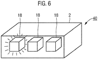
- ein weiteres dreidimensionales Bild eines Teils der Automatisierungsanlage während des Renderns.
- Gleiche Teile sind in allen Figuren mit denselben Bezugszeichen versehen.
-
FIG 1 zeigt schematisch eine Automatisierungsanlage 1, d.h. eine Industrieanlage, in der Produktions- und Verarbeitungsschritte automatisiert erfolgen. Die Industrieanlage umfasst eine Vielzahl von Komponenten, darunter Verarbeitungsstationen 2, zu denen zu verarbeitende Produkte oder deren Vorstufen gebracht werden. Dies geschieht mittels Fördereinrichtungen 4 wie z.B. Förderbändern. - Die Steuerung und Überwachung der Automatisierungsanlage 1 erfolgt in einem Leitsystem 6, wo unter Mitwirkung eines Benutzers mittels entsprechender Daten aus der Automatisierungsanlage 1 die Prozessabläufe überwacht und ggf. beeinflusst werden. Das Leitsystem 6 verfügt hierzu über ein oder mehrere Geräte oder Datenverbindungen 8 zu Geräten an den verschiedenen Komponenten 2, 4 der Automatisierungsanlage 1 zum Messen, Regeln, Steuern, Anzeigen, Alarmieren, Registrieren, Schalten oder Rechnen.
- Die Anzeige des Prozesses erfolgt hierbei über eine Anzeigeeinheit 10, im Ausführungsbeispiel ausgebildet als Bildschirm auf einer mobilen Einheit 12, hier einem Tabletcomputer, der als Teil des Leitsystems 6 mit diesem über eine drahtlose Datenverbindung 14 verbunden ist. Dies bietet dem Benutzer die Möglichkeit der Anzeige und Steuerung der Automatisierungsanlage 1 während er sich frei in der Automatisierungsanlage 1 bewegen kann.
- Auf der Anzeigeeinheit 10 wird die Automatisierungsanlage 1 in echter dreidimensionaler Darstellung inklusive aller Komponenten 2, 4 sowie aller derzeit bearbeiteten Produkte vor und nach dem Zusammenbau dargestellt. Die Erzeugung des jeweiligen Bildes auf der Anzeigeeinheit 10 erfolgt durch übliche Techniken des Renderings in einem nicht näher dargestellten (Grafik-)Prozessor in der mobilen Einheit 12. Das Rendering erfolgt in Echtzeit, so dass einerseits die Darstellung interaktiv ist, d.h. der Benutzer kann durch entsprechende Eingaben Blickwinkel und Position verändern, wobei sich die 3D-Darstellung unmittelbar entsprechend verändert, und andererseits ist dadurch auch ein dynamisches Abbild der Automatisierungsanlage 1 möglich, in der tatsächlich bewegte Komponenten wie z.B. zu verarbeitende Produkte auch in Echtzeit an ihrem jeweils aktuellen Ort dargestellt und mitbewegt werden. Hierfür und für alle anderen im Folgenden dargestellten Funktionen ist im Leitsystem 6 und der mobilen Einheit 12 eine entsprechende Software installiert.
- Die Darstellung der Automatisierungsanlage 1 ist dabei möglichst maßstabsgetreu, d.h. alle Komponenten 2, 4 werden zumindest schematisch in ihrer tatsächlichen Größe und Form sowie in maßstabsgetreuer Lage und Abstand zueinander dargestellt. Hiervon können - zum Zwecke einer verbesserten Darstellung - Abweichungen vorgenommen werden, solange für den Benutzer noch identifizierbar ist, welcher realen Komponente eine Darstellung entspricht. Grundlage hierfür bildet eine datenseitige dreidimensionale Beschreibung der Komponenten 2, 4 der Automatisierungsanlage 1, die sogenannte Szene. Diese wurde mittels geometrischer Modellierung erzeugt. Die entsprechenden Modelldaten werden von einer zentralen Prozessoreinheit ausgewählt und in einen Grafikprozessor der mobilen Einheit 12 geladen. Die Modeldaten können dabei auch auf einem zentralen Server des Leitsystems 6 hinterlegt sein und bedarfsweise an die mobile Einheit 12 übertragen werden. Zusammen mit jeweils aktuellen Positions- und Blickrichtungsdaten wird dann -je nach Leistungsfähigkeit des Grafikprozessors - zyklisch, idealerweise mehrfach pro Sekunde mit bekannten Methoden der Computergrafik der im Blickfeld liegende Teil der Automatisierungsanlage 1 mit ihren Komponenten 2, 4 durch den Grafikprozessor gerendert und auf der Anzeigeeinheit 10 dargestellt.
- Beispielhaft ist ein derartiges gerendertes Bild 16, wie es auf der Anzeigeeinheit 10 dargestellt wird, in
FIG 2 gezeigt. Der Einfachheit der Darstellung halber sind hier und in der Folge sämtliche Komponenten 2, 4 der Automatisierungsanlage 1 als Quader gezeigt, sie werden jedoch in der Realität komplexere Formen aufweisen. Das Bild 16 zeigt eine gerenderte Darstellung einer Verarbeitungseinheit 2, die drei Subkomponenten 18 umfasst. Dies ist in jeder Automatisierungsanlage 1 der Fall: Jede Verarbeitungsstation 2 wird aus verschiedenen Teilen (Roboterarme, Bearbeitungsmaschinen etc.) bestehen. Diese sind in der 3D-Darstellung im Bild 16 ebenfalls weitgehend maßstabsgetreu wiedergegeben und werden vom Prozessor gerendert. - Die Darstellung der Verarbeitungsstation 2 ist dabei in der
FIG 2 halbtransparent, so dass die innenliegenden Subkomponenten 18 sichtbar sind. Eine solche Darstellung ist im Ausführungsbeispiel bei der Auswahl der Verarbeitungsstation 2 als Fokuskomponente während des Übergangs in die neue Darstellung vorgesehen, wie im Folgenden noch erläutert wird. - Jedoch werden in der Realität auch die einzelnen Subkomponenten 18 wiederum aus untergeordneten Komponenten 20 bestehen. Dies ist beispielhaft im Bild 22 in
FIG 3 gezeigt, in dem zwei der drei Subkomponenten 18 wiederum mehrere untergeordnete Komponenten 20 umfassen. Ein Roboterarm besteht z.B. aus einer Vielzahl von Motoren, Greifern, Armgelenken etc. Dies lässt sich beliebig fortsetzen. Jeder Motor besteht wieder aus verschiedenen Teilen, diese Teile können wiederum verschiedene Komponenten umfassen etc. Insoweit diese einzelnen Teile vom Leitsystem 6 der Automatisierungsanlage 1 erfasst sind, muss für jede dieser Komponenten und Unterkomponenten ein Objekt in der die Automatisierungsanlage 1 darstellenden Szene hinterlegt und dieses beim Rendern im Bild 16, 22 dargestellt werden, damit vom Benutzer eine entsprechende Analyse durchgeführt werden kann und ggf. Steuereingriffe vorgenommen werden können. - Hierbei ergibt sich das Problem, dass das Rendering des Bildes 16, 22 sehr leistungsfähige Hardware erfordert, und insbesondere auch das Laden der Modelldaten in den Grafikprozessor vergleichsweise hohe Datenraten erfordert. Dies gilt gerade bei Leitsystemen 6, die sehr große und/oder komplexe Automatisierungsanlagen 1 steuern, und bei denen entsprechend eine vergleichsweise hohe Anzahl von Objekten in der datenseitig gespeicherten Szene vorhanden ist.
- Zur Lösung dieses Problems wird datenseitig eine Baumstruktur 24 geschaffen und in einem Speicher des Leitsystems 6 abgelegt. Die Baumstruktur 24 ist ausschnittsweise in
FIG 4 gezeigt und steht lediglich beispielhaft für mehrere mögliche Baumstrukturen 24, die je nach Anwendungszweck und Rolle des jeweiligen Benutzers hinsichtlich Inhalt und Hierarchie anders ausgestaltet sein können. Auch können mehrere parallele Baumstrukturen 24 datenseitig hinterlegt sein. - Im Ausführungsbeispiel ist die Wurzel 26 der Baumstruktur 24 der Automatisierungsanlage 1 zugeordnet, die weiteren in Hierarchieebenen eingeordneten Knoten 28, 30, 32 sind jeweils einer der Komponenten, d.h. einer Verarbeitungsstation 2, einer Fördereinrichtung 4, einer Subkomponente 18 und sonstigen Komponente 20 zugeordnet. Jede vom Leitsystem 6 angesprochene und als Objekt in der datenseitig gespeicherten Szene für das Rendering hinterlegte Komponente der Automatisierungsanlage 1 wird einem Knoten 28, 30, 32 zugeordnet. Hierbei bildet die Hierarchie der Knoten 28, 30, 32 in der Baumstruktur die oben erläuterte tatsächliche Hierarchie der Komponenten in der Automatisierungsanlage 1 ab.
- Mittels der Baumstruktur 24 erfolgt nun beim Echtzeit-Rendering des Bildes 16, 22 auf der Anzeigeeinheit 10 eine Auswahl der darzustellenden Komponenten 2, 4, 18, 20. Zunächst wird hierzu eine Fokuskomponente ermittelt, d.h. eine Komponente, die für den Benutzer aktuell im Fokus steht. Dies geschieht durch direkte Benutzerauswahl, d.h. z.B. durch Klicken/Antippen der gewünschten Komponente in der 3D-Darstellung, in einer tabellarischen Aufstellung, oder durch eine Suchfunktion.
- Es wird dann in der Baumstruktur 24 derjenige Knoten 34 ermittelt, der der ermittelten Fokuskomponente zugeordnet ist. Ausgehend von diesem Knoten 34 werden dann jeweils aufwärts und abwärts diejenigen Knoten 28, 30, 32 ermittelt, die von dem Knoten 34 der Fokuskomponente nur einen bestimmten Abstand aufweisen, d.h. die über eine bestimmte maximale Anzahl von Kanten erreichbar sind. Im Ausführungsbeispiel sind die Maximalabstände für über- bzw. untergeordnete Komponenten unterschiedlich. Im Anschluss werden dann nur die diesen ermittelten Knoten 28, 30, 32 zugeordneten Komponenten 2, 4, 18, 20 gerendert und im Bild 16, 22 dargestellt. Dies erfolgt dadurch, dass nur die Modelldaten dieser ermittelten Knoten 28, 30, 32 in den Grafikprozessor zum Rendering übertragen werden.
- In unterschiedlichen, nicht bildlich dargestellten Ausführungsbeispielen sind unterschiedliche Bestimmungsverfahren für die Maximalabstände realisiert. In einem ersten Ausführungsbeispiel werden die Maximalabstände durch einen Benutzer direkt eingestellt. Hierfür wird eine Detailniveau-Einstellung durch den Benutzer durchgeführt, die direkt die Maximalabstände vorgibt oder aber aus der Detailniveau-Einstellung indirekt die Maximalabstände ermittelt. In einer zweiten Ausführungsform werden die Maximalabstände dynamisch ermittelt: Hierzu findet während des Rendervorgangs eine Leistungs- oder Geschwindigkeitsmessung des Renderns statt. Aus dem Ergebnis wird eine Leistungskennzahl ermittelt, die letztlich die Leistung des Prozessors bzw. dessen Performance beim Rendervorgang kennzeichnet. Auf Basis dieser Leistungskennzahl werden dann die Maximalabstände ermittelt, wobei bei besserer Leistung höhere Abstände gewählt werden und somit mehr Komponenten 2, 4, 18, 20 dargestellt werden.
- Dies kann auch dazu führen, dass abhängig vom momentanen Blickwinkel und der Anzahl der Subkomponenten der aktuellen Fokuskomponente die Maximalabstände verändert werden und nicht für alle konsekutiven Renderingvorgänge konstant sind.
- Die Maximalabstände können auch je nach aktueller Situation angepasst werden. Im Ausführungsbeispiel sind z.B. während des Übergangs von einer Fokuskomponente zur nächsten andere Maximalabstände definiert. So wird nach einer Auswahl einer neuen Fokuskomponente (z.B. Verarbeitungsstation 2 in
FIG 2 ) die neue Fokuskomponente halbtransparent dargestellt und die untergeordneten Komponenten gezeigt, wie inFIG 2 dargestellt (Erhöhung des Maximalabstandes in Richtung der untergeordneten Hierarchie). Danach erfolgt automatisiert ein Zoomvorgang, d.h. die neu ausgewählte Fokuskomponente wird in den Vordergrund gerückt, durch entsprechende Veränderung des Blickwinkels und Ortes. Erst danach werden übergeordnete Komponenten ausgeblendet (Verringerung des Maximalabstandes in Richtung der übergeordneten Hierarchie) oder nur im Grundriß dargestellt. - In den Ausführungsformen existiert zur weiteren Verbesserung der Performance darüber hinaus auch eine Einstellung, die durch den Benutzer anwählbar ist, und die dazu führt, dass in der Baumstruktur 24 übergeordnete Komponenten, d.h. Elternkomponenten der aktuellen Fokuskomponente nicht vollständig gerendert werden, sonderen nur deren Grundriss oder Umriss gerendert wird.
- In anderen Ausführungsformen ist eine Anzahl von Kategorien definiert und einzelnen oder allen Knoten 28, 30, 32, 34 der Baumstruktur 24 sind eine oder mehrere Kategorien zugeordnet. Beispielsweise können Kategorien sein: Medienelemente wie Leitungen, Kabel, Kanäle oder Förderelemente oder Verarbeitungsstationen. Eine oder mehrere dieser Kategorien können dann vom Benutzer ausgewählt oder auf Basis einer Rolle des Benutzers automatisch ausgewählt werden. Beim Rendering werden dann aus der Szene nur diejenigen Komponenten des Teils der Automatisierungsanlage 1 für das Rendern in den Prozessor geladen, deren jeweils zugeordnete Knoten 28, 30, 32, 34 einer vorgegebenen Kategorie zugeordnet sind. Alle anderen werden dann gar nicht - oder nur mit minimalem Rendering dargestellt.
- Die Eingabe und Veränderung der Positions- und Blickrichtungsdaten durch den Benutzer erfolgt im Ausführungsbeispiel über Eingaben auf der Anzeigeeinheit 10, die in
FIG. 5 gezeigt ist. Der rechteckige Bildschirm der Anzeigeeinheit 10 ist berührungsempfindlich ausgestaltet. Am linken Rand des Bildschirms ist ein vertikaler Balkenbereich 36 angeordnet, der sich über die gesamte Höhe des Bildschirms erstreckt. Am unteren Rand des Bildschirms ist ein horizontaler Balkenbereich 38 angeordnet, der sich über die gesamte Breite des Bildschirms erstreckt. Die Balkenbereiche 36, 38 nehmen im Ausführungsbeispiel ca. 10 % der gesamten Bildschirmfläche ein, können aber auch schmaler oder breiter ausgeführt werden.. - Bei einer horizontalen Bewegung eines die Anzeigeeinheit 10 berührenden Objekts, z.B. eines Fingers, wird eine longitudinale Veränderung der Blickrichtungsdaten durchgeführt. Analog wird bei einer vertikalen Bewegung im vertikalen Balkenbereich 36 eine latidudinale Veränderung der Blickrichtungsdaten durchgeführt. Die Veränderung der Positionsdaten kann z.B. durch Zoomen mit zwei sich aufeinander zu- bzw. voneinander wegbewegenden Fingern erfolgen. Hierdurch kann der Benutzer die jeweils interessierende Komponente 2, 4, 18, 20 in den Fokus bringen. Alternativ können die entsprechenden Orte/Komponenten auch direkt durch Suchfunktionen aufgesucht werden.
- Während des Renderings kann es - trotz der oben dargestellten Maßnahmen zur Beschleunigung und der Auswahl von darzustellenden Komponenten - noch immer zu Wartezeiten beim Laden der Modelldaten von untergeordneten Komponenten 2, 4, 18, 20 kommen. Um dem Benutzer anzuzeigen, dass zu einer dargestellten Komponente noch Subkomponenten fehlen, diese jedoch nicht fertig geladen wurden, wird diese Komponente während des noch unvollständigen Ladevorgangs graphisch abgewandelt dargestellt. Dies ist in
FIG 6 gezeigt, in der ein Bild 40 während des noch unvollständigen Ladevorgangs gezeigt ist. Die im Bild 40 linke Komponente 18 ist zwar bereits dargestellt, es fehlen jedoch noch untergeordnete Komponenten, die noch nicht fertig geladen und gerendert sind. Daher wird die linke Komponente 18 blinkend dargestellt. Nach vollständigem Laden und Rendern der Unterkomponenten wird die Komponente 18 dann in normaler Weise dargestellt. - In einer weiteren, nicht gesondert dargestellten Ausführungsform weist die mobile Einheit 12 Mittel zur räumlichen Lokalisierung innerhalb der Automatisierungsanlage 1 auf. Dadurch wird es ermöglicht, den Blickwinkel und den Standort in der 3D-Darstellung auf der Anzeigeeinheit 10 dem aktuellen Blickwinkel und Standort der mobilen Einheit 12 und damit des Benutzers anzupassen. Dies erfolgt beispielsweise beim Hochfahren der mobilen Eineit 12 oder beim Klicken/Antippen einer "Home"-Schaltfläche.
-
- 1
- Automatisierungsanlage
- 2
- Verarbeitungsstation
- 4
- Fördereinrichtung
- 6
- Leitsystem
- 8
- Datenverbindung
- 10
- Anzeigeeinheit
- 12
- mobile Einheit
- 14
- drahtlose Datenverbindung
- 16
- Bild
- 18
- Subkomponente
- 20
- Komponente
- 22
- Bild
- 24
- Baumstruktur
- 26
- Wurzel
- 28, 30 32, 34
- Knoten
- 36
- vertikaler Balkenbereich
- 38
- horizontaler Balkenbereich
- 40
- Bild
Claims (15)
- Verfahren zur Steuerung einer Automatisierungsanlage (1), umfassend:Rendern, durch einen Prozessor, eines Bildes (16, 22, 40) aus einer zumindest einen Teil der Automatisierungsanlage (1) darstellenden, dreidimensionalen Szene auf Basis von Positionsdaten und Blickrichtungsdaten,Darstellen des Bildes (16, 22, 40) auf einer Anzeigeeinheit (10),wobei die Automatisierungsanlage (1) eine Vielzahl von Komponenten (2, 4, 18, 20) umfasst, wobei in einem Datenspeicher eine Baumstruktur (24) hinterlegt wird, in der den Komponenten (2, 4, 18, 20) der Automatisierungsanlage (1) jeweils Knoten (28, 30, 32, 34) zugeordnet sind,wobei eine Fokuskomponente ermittelt wird, und aus der Szene nur diejenigen Komponenten (2, 4, 18, 20) des Teils der Automatisierungsanlage (1) für das Rendern in den Prozessor geladen werden, deren jeweils zugeordnete Knoten (28, 30, 32, 34) in der Baumstruktur (24) nur einen vorbestimmten Maximalabstand von dem der Fokuskomponente zugeordneten Knoten (28, 30, 32, 34) aufweisen.
- Verfahren nach Anspruch 1, bei dem die Fokuskomponente aus einer Benutzereingabe ermittelt wird.
- Verfahren nach einem der vorhergehenden Ansprüche, bei dem für Eltern- und Kindknoten des der Fokuskomponente zugeordneten Knotens (28, 30, 32, 34) unterschiedliche Maximalabstände vorbestimmt werden.
- Verfahren nach einem der vorhergehenden Ansprüche, bei dem der jeweilige Maximalabstand auf Basis einer durch einen Benutzer getroffenen Detailniveau-Einstellung vorbestimmt wird.
- Verfahren nach einem der vorhergehenden Ansprüche, wobei eine Komponente (2, 4, 18, 20), deren zugeordneter Knoten (28, 30, 32, 34) ein Elternknoten des der Fokuskomponente zugeordneten Knotens (28, 30, 32, 34) ist, in dem Bild (16, 22, 40) nur im Grundriß oder Umriß dargestellt wird.
- Verfahren nach einem der vorhergehenden Ansprüche, bei dem während des Ladens einer ersten Komponente (2, 4, 18, 20) aus der Szene, deren zugeordneter Knoten (28, 30, 32, 34) ein Kindknoten einer zweiten Komponente(2, 4, 18, 20) aus der Szene ist, die zweite Komponente (2, 4, 18, 20) gegenüber einer vorgegebenen Normaldarstellung in dem Bild (16, 22, 40) graphisch abgewandelt wird, und erst nach vollständigem Laden der ersten Komponente (2, 4, 18, 20) die zweite Komponente (2, 4, 18, 20) in der vorgegebenen Normaldarstellung dargestellt wird.
- Verfahren nach einem der vorhergehenden Ansprüche, bei dem die Positionsdaten und Blickrichtungsdaten auf Basis der räumlichen Positionierung der Anzeigeeinheit (10) ermittelt werden.
- Verfahren nach einem der vorhergehenden Ansprüche, bei dem eine Anzahl von Kategorien definiert wird und einer Anzahl von Knoten (28, 30, 32, 34) der Baumstruktur (24) eine oder mehrere Kategorien zugeordnet werden,
wobei aus der Szene nur diejenigen Komponenten (2, 4, 18, 20) des Teils der Automatisierungsanlage (1) für das Rendern in den Prozessor geladen werden, deren jeweils zugeordnete Knoten (28, 30, 32, 34) einer vorgegebenen Kategorie zugeordnet sind. - Verfahren nach einem der vorhergehenden Ansprüche, bei dem nach jeder Änderung der Positionsdaten oder der Blickrichtungsdaten durch eine Benutzereingabe die Verfahrensschritte des Renderns und des Darstellens erneut durchgeführt werden.
- Verfahren nach Anspruch 9, bei dem während des Renderns eine Leistungskenngröße für den Prozessor ermittelt wird, wobei bei der nächsten Durchführung des Renderns der jeweilige Maximalabstand auf Basis der Leistungskenngröße vorbestimmt wird.
- Verfahren nach Anspruch 9 oder 10, bei dem die Anzeigeeinheit (10) berührungsempfindlich ist und ein Bildschirmrandbereich (36, 38) vorgesehen wird, und wobei bei einer horizontalen Berührungseingabe im Bildschirmrandbereich (36, 38) eine longitudinale Veränderung der Blickrichtungsdaten durchgeführt wird und/oder einer vertikalen Berührungseingabe im Bildschirmrandbereich eine latidudinale Veränderung der Blickrichtungsdaten durchgeführt wird.
- Verfahren nach Anspruch 11, wobei der Bildschirmrandbereich (36, 38) einen horizontalen und einen vertikalen Balkenbereich (36, 38) umfasst, wobei die horizontale Berührungseingabe im horizontalen Balkenbereich (38) erfolgt und die vertikale Berührungseingabe im vertikalen Balkenbereich (36) erfolgt.
- Computerprogrammprodukt, welches Softwarecodeabschnitte umfasst, die, wenn sie auf einem Prozessor ausgeführt werden, den Prozessor zum Ausführen des Verfahrens nach einem der vorhergehenden Ansprüche veranlassen.
- Leitsystem (6) für eine Automatisierungsanlage (1), umfassend einen Prozessor und eine Anzeigeeinheit (10), wobei auf dem Prozessor das Verfahren nach einem der Ansprüche 1 bis 12 ausgeführt wird.
- Leitsystem (6) nach Anspruch 14, dessen Anzeigeeinheit (10) auf einer mobilen, mit der Automatisierungsanlage (1) und/oder weiteren Komponenten des Leitsystems (6) durch eine drahtlose Kommunikationsverbindung (14) verbundenen Einheit (12) angeordnet ist.
Priority Applications (3)
| Application Number | Priority Date | Filing Date | Title |
|---|---|---|---|
| EP17177504.2A EP3418839B1 (de) | 2017-06-22 | 2017-06-22 | Verfahren zur überwachung einer automatisierungsanlage |
| US16/014,517 US10761523B2 (en) | 2017-06-22 | 2018-06-21 | Method for controlling an automation system |
| CN201810649461.XA CN109118584B (zh) | 2017-06-22 | 2018-06-22 | 控制自动化系统的方法、控制系统及计算机程序产品 |
Applications Claiming Priority (1)
| Application Number | Priority Date | Filing Date | Title |
|---|---|---|---|
| EP17177504.2A EP3418839B1 (de) | 2017-06-22 | 2017-06-22 | Verfahren zur überwachung einer automatisierungsanlage |
Publications (2)
| Publication Number | Publication Date |
|---|---|
| EP3418839A1 true EP3418839A1 (de) | 2018-12-26 |
| EP3418839B1 EP3418839B1 (de) | 2021-10-13 |
Family
ID=59227502
Family Applications (1)
| Application Number | Title | Priority Date | Filing Date |
|---|---|---|---|
| EP17177504.2A Active EP3418839B1 (de) | 2017-06-22 | 2017-06-22 | Verfahren zur überwachung einer automatisierungsanlage |
Country Status (3)
| Country | Link |
|---|---|
| US (1) | US10761523B2 (de) |
| EP (1) | EP3418839B1 (de) |
| CN (1) | CN109118584B (de) |
Cited By (1)
| Publication number | Priority date | Publication date | Assignee | Title |
|---|---|---|---|---|
| CN114842117A (zh) * | 2022-04-06 | 2022-08-02 | 邦彦技术股份有限公司 | 数据处理方法、电子设备及存储介质 |
Families Citing this family (3)
| Publication number | Priority date | Publication date | Assignee | Title |
|---|---|---|---|---|
| CN108376424A (zh) * | 2018-02-09 | 2018-08-07 | 腾讯科技(深圳)有限公司 | 用于对三维虚拟环境进行视角切换的方法、装置、设备及存储介质 |
| EP3686700B1 (de) * | 2018-07-27 | 2020-12-16 | Eisenmann SE | Verfahren zur überwachung einer automatisierungsanlage |
| EP3742240A1 (de) * | 2019-05-22 | 2020-11-25 | Siemens Aktiengesellschaft | Verfahren und engineering-system zur änderung eines programms einer industriellen automatisierungskomponente |
Citations (5)
| Publication number | Priority date | Publication date | Assignee | Title |
|---|---|---|---|---|
| US6282455B1 (en) * | 1998-10-19 | 2001-08-28 | Rockwell Technologies, Llc | Walk-through human/machine interface for industrial control |
| WO2003001334A2 (en) * | 2001-06-22 | 2003-01-03 | Wonderware Corporation | Remotely monitoring / diagnosing distributed components of a supervisory process control and manufacturing information application from a central location |
| WO2006001629A1 (en) * | 2004-06-23 | 2006-01-05 | Nhn Corporation | Image resource loading system and method which carries out loading of object for removal of game screen |
| US7817150B2 (en) | 2005-09-30 | 2010-10-19 | Rockwell Automation Technologies, Inc. | Three-dimensional immersive system for representing an automation control environment |
| DE102012102749A1 (de) * | 2012-03-29 | 2013-10-02 | Reis Group Holding Gmbh & Co. Kg | Vorrichtung und Verfahren zur Bedienung eines Industrieroboters |
Family Cites Families (7)
| Publication number | Priority date | Publication date | Assignee | Title |
|---|---|---|---|---|
| US20060036615A1 (en) * | 2004-08-12 | 2006-02-16 | International Business Machines Corporation | Method, system, and computer program product for navigating and displaying very large trees |
| US8055727B2 (en) * | 2005-09-22 | 2011-11-08 | Fisher-Rosemount Systems, Inc. | Use of a really simple syndication communication format in a process control system |
| CN101617343A (zh) * | 2007-12-21 | 2009-12-30 | 工作室图形处理器公司 | 快速渲染三维场景的方法和系统 |
| CN100568290C (zh) * | 2008-04-22 | 2009-12-09 | 北京航空航天大学 | 一种可快速配置和实时渲染的安防三维电子地图系统 |
| JP2011059820A (ja) * | 2009-09-07 | 2011-03-24 | Sony Corp | 情報処理装置、情報処理方法、およびプログラム |
| US8983778B2 (en) * | 2012-06-05 | 2015-03-17 | Apple Inc. | Generation of intersection information by a mapping service |
| EP2911118A1 (de) * | 2014-02-19 | 2015-08-26 | My Virtual Reality Software AS | Verfahren zur Auswahl von Datendateien zum Herunterladen |
-
2017
- 2017-06-22 EP EP17177504.2A patent/EP3418839B1/de active Active
-
2018
- 2018-06-21 US US16/014,517 patent/US10761523B2/en active Active
- 2018-06-22 CN CN201810649461.XA patent/CN109118584B/zh active Active
Patent Citations (5)
| Publication number | Priority date | Publication date | Assignee | Title |
|---|---|---|---|---|
| US6282455B1 (en) * | 1998-10-19 | 2001-08-28 | Rockwell Technologies, Llc | Walk-through human/machine interface for industrial control |
| WO2003001334A2 (en) * | 2001-06-22 | 2003-01-03 | Wonderware Corporation | Remotely monitoring / diagnosing distributed components of a supervisory process control and manufacturing information application from a central location |
| WO2006001629A1 (en) * | 2004-06-23 | 2006-01-05 | Nhn Corporation | Image resource loading system and method which carries out loading of object for removal of game screen |
| US7817150B2 (en) | 2005-09-30 | 2010-10-19 | Rockwell Automation Technologies, Inc. | Three-dimensional immersive system for representing an automation control environment |
| DE102012102749A1 (de) * | 2012-03-29 | 2013-10-02 | Reis Group Holding Gmbh & Co. Kg | Vorrichtung und Verfahren zur Bedienung eines Industrieroboters |
Cited By (1)
| Publication number | Priority date | Publication date | Assignee | Title |
|---|---|---|---|---|
| CN114842117A (zh) * | 2022-04-06 | 2022-08-02 | 邦彦技术股份有限公司 | 数据处理方法、电子设备及存储介质 |
Also Published As
| Publication number | Publication date |
|---|---|
| EP3418839B1 (de) | 2021-10-13 |
| CN109118584B (zh) | 2023-06-23 |
| US20190004506A1 (en) | 2019-01-03 |
| CN109118584A (zh) | 2019-01-01 |
| US10761523B2 (en) | 2020-09-01 |
Similar Documents
| Publication | Publication Date | Title |
|---|---|---|
| DE102019002898B4 (de) | Robotersimulationsvorrichtung | |
| EP1447770B1 (de) | Verfahren und Vorrichtung zur Visualisierung rechnergestützter Informationen | |
| DE102010036499B4 (de) | Werkzeugvektor-Anzeigevorrichtung für eine Werkzeugmaschine mit Drehachse | |
| DE69735269T2 (de) | Steuerverfahren zum schrittbetrieb eines roboters | |
| DE102015011830C5 (de) | Robotersystem zum Einstellen eines Bewegungsüberwachungsbereichs eines Roboters | |
| EP3418839B1 (de) | Verfahren zur überwachung einer automatisierungsanlage | |
| EP3725472A1 (de) | Verfahren zum ermitteln einer trajektorie eines roboters | |
| WO2005045729A1 (de) | System und verfahren zur durchführung und visualisierung von simulationen in einer erweiterten realität | |
| EP1148398B1 (de) | Eingabeverfahren für die Programmierung von industriellen Steuerungen | |
| EP2952989A1 (de) | Verfahren zur berechnung einer optimierten trajektorie | |
| WO2016141998A1 (de) | Vorrichtung und verfahren zum bereitstellen einer digitalen abbildung einer physikalischen entität | |
| DE102007058352A1 (de) | Programmerstellung durch Ableiten des Prozesssteuerungsablaufes durch Zuordnung von Funktionen dynamischer Grafikobjekte | |
| DE10393527T5 (de) | Systeme und Verfahren zur Darstellung komplexer n-Kurven für die Direktsteuerung einer Werkzeugbewegung | |
| EP3044643B1 (de) | Navigationssystem für reinräume | |
| EP3969970A1 (de) | Verfahren zur darstellung und bedienung von produktionsmitteln, insbesondere für die kunststoffverarbeitende industrie | |
| WO2019233735A1 (de) | Verfahren zur qualitätssicherung bei der produktion eines produktes sowie recheneinrichtung und computerprogramm | |
| DE102005011126A1 (de) | Generierung virtueller Welten auf Basis einer realen Umgebung | |
| EP3972924B1 (de) | Verfahren und vorrichtung zum visualisieren von ersatzteilen | |
| EP3295265B1 (de) | Bedienmodul für eine maschine in der lebensmittelindustrie | |
| EP0564538B1 (de) | Verfahren zur computergestützten steuerung einer maschine bzw. eines prozesses | |
| EP3686700B1 (de) | Verfahren zur überwachung einer automatisierungsanlage | |
| EP1403863A2 (de) | Vorrichtung und Verfahren zum Auffinden und Darstellen von Informationen | |
| WO2019192844A1 (de) | Verfahren und vorrichtung zur darstellung und anpassung von konfigurationen von anlagekomponenten | |
| DE102006051533A1 (de) | Bedienungshilfe für eine Vorrichtung zum Behandeln von Behältnissen (II) | |
| DE102021117448A1 (de) | Steuerverfahren für ein teleoperiertes kraftfahrzeug |
Legal Events
| Date | Code | Title | Description |
|---|---|---|---|
| PUAI | Public reference made under article 153(3) epc to a published international application that has entered the european phase |
Free format text: ORIGINAL CODE: 0009012 |
|
| STAA | Information on the status of an ep patent application or granted ep patent |
Free format text: STATUS: THE APPLICATION HAS BEEN PUBLISHED |
|
| AK | Designated contracting states |
Kind code of ref document: A1 Designated state(s): AL AT BE BG CH CY CZ DE DK EE ES FI FR GB GR HR HU IE IS IT LI LT LU LV MC MK MT NL NO PL PT RO RS SE SI SK SM TR |
|
| AX | Request for extension of the european patent |
Extension state: BA ME |
|
| STAA | Information on the status of an ep patent application or granted ep patent |
Free format text: STATUS: REQUEST FOR EXAMINATION WAS MADE |
|
| 17P | Request for examination filed |
Effective date: 20190129 |
|
| RBV | Designated contracting states (corrected) |
Designated state(s): AL AT BE BG CH CY CZ DE DK EE ES FI FR GB GR HR HU IE IS IT LI LT LU LV MC MK MT NL NO PL PT RO RS SE SI SK SM TR |
|
| 19U | Interruption of proceedings before grant |
Effective date: 20190731 |
|
| 19W | Proceedings resumed before grant after interruption of proceedings |
Effective date: 20200803 |
|
| RAP1 | Party data changed (applicant data changed or rights of an application transferred) |
Owner name: ENISCO BY FORCAM GMBH |
|
| GRAP | Despatch of communication of intention to grant a patent |
Free format text: ORIGINAL CODE: EPIDOSNIGR1 |
|
| RIC1 | Information provided on ipc code assigned before grant |
Ipc: G05B 23/02 20060101AFI20210415BHEP Ipc: G05B 19/042 20060101ALI20210415BHEP Ipc: G06F 3/0485 20130101ALI20210415BHEP Ipc: G06T 15/00 20110101ALI20210415BHEP Ipc: G06F 3/0488 20130101ALI20210415BHEP |
|
| STAA | Information on the status of an ep patent application or granted ep patent |
Free format text: STATUS: GRANT OF PATENT IS INTENDED |
|
| INTG | Intention to grant announced |
Effective date: 20210520 |
|
| GRAS | Grant fee paid |
Free format text: ORIGINAL CODE: EPIDOSNIGR3 |
|
| GRAA | (expected) grant |
Free format text: ORIGINAL CODE: 0009210 |
|
| STAA | Information on the status of an ep patent application or granted ep patent |
Free format text: STATUS: THE PATENT HAS BEEN GRANTED |
|
| AK | Designated contracting states |
Kind code of ref document: B1 Designated state(s): AL AT BE BG CH CY CZ DE DK EE ES FI FR GB GR HR HU IE IS IT LI LT LU LV MC MK MT NL NO PL PT RO RS SE SI SK SM TR |
|
| REG | Reference to a national code |
Ref country code: GB Ref legal event code: FG4D Free format text: NOT ENGLISH |
|
| REG | Reference to a national code |
Ref country code: CH Ref legal event code: EP |
|
| REG | Reference to a national code |
Ref country code: DE Ref legal event code: R096 Ref document number: 502017011707 Country of ref document: DE |
|
| REG | Reference to a national code |
Ref country code: IE Ref legal event code: FG4D Free format text: LANGUAGE OF EP DOCUMENT: GERMAN |
|
| REG | Reference to a national code |
Ref country code: AT Ref legal event code: REF Ref document number: 1438630 Country of ref document: AT Kind code of ref document: T Effective date: 20211115 |
|
| REG | Reference to a national code |
Ref country code: SE Ref legal event code: TRGR |
|
| REG | Reference to a national code |
Ref country code: LT Ref legal event code: MG9D |
|
| REG | Reference to a national code |
Ref country code: NL Ref legal event code: MP Effective date: 20211013 |
|
| PG25 | Lapsed in a contracting state [announced via postgrant information from national office to epo] |
Ref country code: RS Free format text: LAPSE BECAUSE OF FAILURE TO SUBMIT A TRANSLATION OF THE DESCRIPTION OR TO PAY THE FEE WITHIN THE PRESCRIBED TIME-LIMIT Effective date: 20211013 Ref country code: LT Free format text: LAPSE BECAUSE OF FAILURE TO SUBMIT A TRANSLATION OF THE DESCRIPTION OR TO PAY THE FEE WITHIN THE PRESCRIBED TIME-LIMIT Effective date: 20211013 Ref country code: FI Free format text: LAPSE BECAUSE OF FAILURE TO SUBMIT A TRANSLATION OF THE DESCRIPTION OR TO PAY THE FEE WITHIN THE PRESCRIBED TIME-LIMIT Effective date: 20211013 Ref country code: BG Free format text: LAPSE BECAUSE OF FAILURE TO SUBMIT A TRANSLATION OF THE DESCRIPTION OR TO PAY THE FEE WITHIN THE PRESCRIBED TIME-LIMIT Effective date: 20220113 |
|
| PG25 | Lapsed in a contracting state [announced via postgrant information from national office to epo] |
Ref country code: IS Free format text: LAPSE BECAUSE OF FAILURE TO SUBMIT A TRANSLATION OF THE DESCRIPTION OR TO PAY THE FEE WITHIN THE PRESCRIBED TIME-LIMIT Effective date: 20220213 Ref country code: PT Free format text: LAPSE BECAUSE OF FAILURE TO SUBMIT A TRANSLATION OF THE DESCRIPTION OR TO PAY THE FEE WITHIN THE PRESCRIBED TIME-LIMIT Effective date: 20220214 Ref country code: PL Free format text: LAPSE BECAUSE OF FAILURE TO SUBMIT A TRANSLATION OF THE DESCRIPTION OR TO PAY THE FEE WITHIN THE PRESCRIBED TIME-LIMIT Effective date: 20211013 Ref country code: NO Free format text: LAPSE BECAUSE OF FAILURE TO SUBMIT A TRANSLATION OF THE DESCRIPTION OR TO PAY THE FEE WITHIN THE PRESCRIBED TIME-LIMIT Effective date: 20220113 Ref country code: NL Free format text: LAPSE BECAUSE OF FAILURE TO SUBMIT A TRANSLATION OF THE DESCRIPTION OR TO PAY THE FEE WITHIN THE PRESCRIBED TIME-LIMIT Effective date: 20211013 Ref country code: LV Free format text: LAPSE BECAUSE OF FAILURE TO SUBMIT A TRANSLATION OF THE DESCRIPTION OR TO PAY THE FEE WITHIN THE PRESCRIBED TIME-LIMIT Effective date: 20211013 Ref country code: HR Free format text: LAPSE BECAUSE OF FAILURE TO SUBMIT A TRANSLATION OF THE DESCRIPTION OR TO PAY THE FEE WITHIN THE PRESCRIBED TIME-LIMIT Effective date: 20211013 Ref country code: GR Free format text: LAPSE BECAUSE OF FAILURE TO SUBMIT A TRANSLATION OF THE DESCRIPTION OR TO PAY THE FEE WITHIN THE PRESCRIBED TIME-LIMIT Effective date: 20220114 Ref country code: ES Free format text: LAPSE BECAUSE OF FAILURE TO SUBMIT A TRANSLATION OF THE DESCRIPTION OR TO PAY THE FEE WITHIN THE PRESCRIBED TIME-LIMIT Effective date: 20211013 |
|
| REG | Reference to a national code |
Ref country code: DE Ref legal event code: R097 Ref document number: 502017011707 Country of ref document: DE |
|
| PG25 | Lapsed in a contracting state [announced via postgrant information from national office to epo] |
Ref country code: SM Free format text: LAPSE BECAUSE OF FAILURE TO SUBMIT A TRANSLATION OF THE DESCRIPTION OR TO PAY THE FEE WITHIN THE PRESCRIBED TIME-LIMIT Effective date: 20211013 Ref country code: SK Free format text: LAPSE BECAUSE OF FAILURE TO SUBMIT A TRANSLATION OF THE DESCRIPTION OR TO PAY THE FEE WITHIN THE PRESCRIBED TIME-LIMIT Effective date: 20211013 Ref country code: RO Free format text: LAPSE BECAUSE OF FAILURE TO SUBMIT A TRANSLATION OF THE DESCRIPTION OR TO PAY THE FEE WITHIN THE PRESCRIBED TIME-LIMIT Effective date: 20211013 Ref country code: EE Free format text: LAPSE BECAUSE OF FAILURE TO SUBMIT A TRANSLATION OF THE DESCRIPTION OR TO PAY THE FEE WITHIN THE PRESCRIBED TIME-LIMIT Effective date: 20211013 Ref country code: DK Free format text: LAPSE BECAUSE OF FAILURE TO SUBMIT A TRANSLATION OF THE DESCRIPTION OR TO PAY THE FEE WITHIN THE PRESCRIBED TIME-LIMIT Effective date: 20211013 Ref country code: CZ Free format text: LAPSE BECAUSE OF FAILURE TO SUBMIT A TRANSLATION OF THE DESCRIPTION OR TO PAY THE FEE WITHIN THE PRESCRIBED TIME-LIMIT Effective date: 20211013 |
|
| PLBE | No opposition filed within time limit |
Free format text: ORIGINAL CODE: 0009261 |
|
| STAA | Information on the status of an ep patent application or granted ep patent |
Free format text: STATUS: NO OPPOSITION FILED WITHIN TIME LIMIT |
|
| 26N | No opposition filed |
Effective date: 20220714 |
|
| PG25 | Lapsed in a contracting state [announced via postgrant information from national office to epo] |
Ref country code: AL Free format text: LAPSE BECAUSE OF FAILURE TO SUBMIT A TRANSLATION OF THE DESCRIPTION OR TO PAY THE FEE WITHIN THE PRESCRIBED TIME-LIMIT Effective date: 20211013 |
|
| PG25 | Lapsed in a contracting state [announced via postgrant information from national office to epo] |
Ref country code: SI Free format text: LAPSE BECAUSE OF FAILURE TO SUBMIT A TRANSLATION OF THE DESCRIPTION OR TO PAY THE FEE WITHIN THE PRESCRIBED TIME-LIMIT Effective date: 20211013 |
|
| PG25 | Lapsed in a contracting state [announced via postgrant information from national office to epo] |
Ref country code: MC Free format text: LAPSE BECAUSE OF FAILURE TO SUBMIT A TRANSLATION OF THE DESCRIPTION OR TO PAY THE FEE WITHIN THE PRESCRIBED TIME-LIMIT Effective date: 20211013 |
|
| REG | Reference to a national code |
Ref country code: CH Ref legal event code: PL |
|
| REG | Reference to a national code |
Ref country code: BE Ref legal event code: MM Effective date: 20220630 |
|
| PG25 | Lapsed in a contracting state [announced via postgrant information from national office to epo] |
Ref country code: LU Free format text: LAPSE BECAUSE OF NON-PAYMENT OF DUE FEES Effective date: 20220622 Ref country code: LI Free format text: LAPSE BECAUSE OF NON-PAYMENT OF DUE FEES Effective date: 20220630 Ref country code: IE Free format text: LAPSE BECAUSE OF NON-PAYMENT OF DUE FEES Effective date: 20220622 Ref country code: CH Free format text: LAPSE BECAUSE OF NON-PAYMENT OF DUE FEES Effective date: 20220630 |
|
| PG25 | Lapsed in a contracting state [announced via postgrant information from national office to epo] |
Ref country code: BE Free format text: LAPSE BECAUSE OF NON-PAYMENT OF DUE FEES Effective date: 20220630 |
|
| REG | Reference to a national code |
Ref country code: AT Ref legal event code: MM01 Ref document number: 1438630 Country of ref document: AT Kind code of ref document: T Effective date: 20220622 |
|
| PG25 | Lapsed in a contracting state [announced via postgrant information from national office to epo] |
Ref country code: AT Free format text: LAPSE BECAUSE OF NON-PAYMENT OF DUE FEES Effective date: 20220622 |
|
| PG25 | Lapsed in a contracting state [announced via postgrant information from national office to epo] |
Ref country code: HU Free format text: LAPSE BECAUSE OF FAILURE TO SUBMIT A TRANSLATION OF THE DESCRIPTION OR TO PAY THE FEE WITHIN THE PRESCRIBED TIME-LIMIT; INVALID AB INITIO Effective date: 20170622 |
|
| PG25 | Lapsed in a contracting state [announced via postgrant information from national office to epo] |
Ref country code: MK Free format text: LAPSE BECAUSE OF FAILURE TO SUBMIT A TRANSLATION OF THE DESCRIPTION OR TO PAY THE FEE WITHIN THE PRESCRIBED TIME-LIMIT Effective date: 20211013 Ref country code: CY Free format text: LAPSE BECAUSE OF FAILURE TO SUBMIT A TRANSLATION OF THE DESCRIPTION OR TO PAY THE FEE WITHIN THE PRESCRIBED TIME-LIMIT Effective date: 20211013 |
|
| PG25 | Lapsed in a contracting state [announced via postgrant information from national office to epo] |
Ref country code: TR Free format text: LAPSE BECAUSE OF FAILURE TO SUBMIT A TRANSLATION OF THE DESCRIPTION OR TO PAY THE FEE WITHIN THE PRESCRIBED TIME-LIMIT Effective date: 20211013 |
|
| PG25 | Lapsed in a contracting state [announced via postgrant information from national office to epo] |
Ref country code: MT Free format text: LAPSE BECAUSE OF FAILURE TO SUBMIT A TRANSLATION OF THE DESCRIPTION OR TO PAY THE FEE WITHIN THE PRESCRIBED TIME-LIMIT Effective date: 20211013 |
|
| PGFP | Annual fee paid to national office [announced via postgrant information from national office to epo] |
Ref country code: GB Payment date: 20250630 Year of fee payment: 9 |
|
| PGFP | Annual fee paid to national office [announced via postgrant information from national office to epo] |
Ref country code: FR Payment date: 20250630 Year of fee payment: 9 |
|
| PGFP | Annual fee paid to national office [announced via postgrant information from national office to epo] |
Ref country code: SE Payment date: 20250618 Year of fee payment: 9 |
|
| PGFP | Annual fee paid to national office [announced via postgrant information from national office to epo] |
Ref country code: DE Payment date: 20250707 Year of fee payment: 9 |
|
| PGFP | Annual fee paid to national office [announced via postgrant information from national office to epo] |
Ref country code: IT Payment date: 20250630 Year of fee payment: 9 |