EP3418759A1 - Magnetic hybrid amr/phr based sensing device and method for measuring a local magnetic field - Google Patents
Magnetic hybrid amr/phr based sensing device and method for measuring a local magnetic field Download PDFInfo
- Publication number
- EP3418759A1 EP3418759A1 EP17305787.8A EP17305787A EP3418759A1 EP 3418759 A1 EP3418759 A1 EP 3418759A1 EP 17305787 A EP17305787 A EP 17305787A EP 3418759 A1 EP3418759 A1 EP 3418759A1
- Authority
- EP
- European Patent Office
- Prior art keywords
- magnetic field
- magnetic
- track
- transmitter
- pair
- Prior art date
- Legal status (The legal status is an assumption and is not a legal conclusion. Google has not performed a legal analysis and makes no representation as to the accuracy of the status listed.)
- Granted
Links
Images





Classifications
-
- G—PHYSICS
- G01—MEASURING; TESTING
- G01R—MEASURING ELECTRIC VARIABLES; MEASURING MAGNETIC VARIABLES
- G01R33/00—Arrangements or instruments for measuring magnetic variables
- G01R33/02—Measuring direction or magnitude of magnetic fields or magnetic flux
- G01R33/06—Measuring direction or magnitude of magnetic fields or magnetic flux using galvano-magnetic devices
- G01R33/09—Magnetoresistive devices
- G01R33/096—Magnetoresistive devices anisotropic magnetoresistance sensors
-
- G—PHYSICS
- G01—MEASURING; TESTING
- G01R—MEASURING ELECTRIC VARIABLES; MEASURING MAGNETIC VARIABLES
- G01R33/00—Arrangements or instruments for measuring magnetic variables
- G01R33/02—Measuring direction or magnitude of magnetic fields or magnetic flux
- G01R33/06—Measuring direction or magnitude of magnetic fields or magnetic flux using galvano-magnetic devices
- G01R33/07—Hall effect devices
Definitions
- the present invention concerns a magnetic measurement device and a system based on an ultrasensitive Planar Hall magneto-resistive sensor for measuring locally a time varying magnetic free field generated remotely by one or several magnetic source(s) or for measuring tiny quantities of magnetic particles deposited closely to the sensor.
- the invention also relates to a method using the magnetic measurement device and system according to the invention for measuring locally an alternative magnetic free field or for measuring locally a time varying magnetic free field generated remotely by one or several magnetic source(s) or for measuring tiny quantities of magnetic particles deposited closely to the sensor.
- MR magneto-resistive
- MR sensors such as semiconductor Hall sensor, anisotropic magnetoresistive (AMR), giant magnetoresistive (GMR), tunneling magnetoresistive (TMR) and giant magneto-impedance (GMI) sensors.
- AMR anisotropic magnetoresistive
- GMR giant magnetoresistive
- TMR tunneling magnetoresistive
- GMI giant magneto-impedance
- These sensors are able to detect small quantities of magnetic particles and/or concentrations of these magnetic particles and described in several papers.
- PHR Planar Hall Magnetoresistive
- the Planar Hall Magnetoresistive (PHR) sensors are Anisotropic Magneto Resistance (AMR) coupled with planar Hall effect (PHE) sensors that present a linear dependence as a function of small external field, a very high sensitivity and a high signal-to-noise ratio. These sensors are a growing center of interest in the domain of local magnetic field detection of micro- nano-beads and particularly in the field of magnetic phase transition of bi-stable nano-particles.
- Hall Magnetoresistive sensors as described in the cited patents still need a relatively high power external biasing field, thus precluding most low power portable battery powered applications.
- a first technical problem is to propose a portable magnetic hybrid AMR/PHR sensing device for detecting local magnitude and/or variation of a magnetic field generated remotely or closely by one or several magnetic source(s) wherein the power consumption is decreased while keeping a high sensitivity.
- a second technical problem is to propose a portable magnetic hybrid AMR/PHR sensing device for detecting local magnitude and/or variation of a magnetic field generated remotely or closely by one or several magnetic source(s) wherein the power consumption is decreased while keeping a high sensitivity and operating at low temperature ranging from 4°K to 400°K.
- a third technical problem is to propose a method for detecting local magnitude and/or variation of a magnetic field generated remotely or closely by one or several magnetic source(s) that uses a portable magnetic hybrid AMR/PHR sensing device with low power consumption while keeping a high measurement sensitivity.
- the invention aims at solving the first, second and third technical problems.
- the invention relates to a magnetic hybrid AMR/PHR based sensing device for detecting local magnitude and/or variation of a magnetic field generated remotely or closely by one or several magnetic source(s), and comprising a magnetic field receiver, as a first component, having a structure of a magnetic hybrid AMR/PHR sensor and that includes a magnetoresistive first track with a closed loop shape or a cross junction shape; a first pair of current terminals formed with a first current terminal and a second current terminal, facing each other, contacting with the magnetoresistive first track and forming a first easy axis; a first pair of voltage terminals formed with a first voltage terminal and a second voltage terminal, facing each other, contacting with the magnetoresistive first track and forming a first hard axis, orthogonal to the first easy axis.
- the magnetic hybrid AMR/PHR based sensing device is characterized in that it comprises a first magnetic field transmitter as a second component, configured for being excited by a DC and/or AC supplied bias current or by an external magnetic field to be measured and that includes:
- the magnetic hybrid AMR/PHR based sensing device is also characterized in that the magnetic field receiver and the magnetic field transmitter are superimposed, secured to and separated by a first insulating spacer configured to align respectively the first easy axis and the first hard axis to the second easy axis and the second hard axis, then rotate the said second axis from said first axis at a predetermines fixed offset angle ⁇ , and to maintain this axis arrangement as well as a fixed separation distance e 12 between the first track and the second track in a range from few micrometers to few nanometers.
- the magnetic measurement system might incorporate one or several of the following features, taken in any technically admissible combination:
- the invention also relates to a magnetic measurement method for measuring local magnitude and/or variation of a magnetic field generated remotely or closely by one or several magnetic source(s) according to a first embodiment.
- the magnetic measuring method comprises the steps of :
- the invention also relates to a magnetic measurement method for measuring local amplitude and/or variation of a magnetic field generated by one or several magnetic source(s).
- the magnetic measuring method comprises the steps of :
- the invention also relates to a magnetic measurement method for measuring local amplitude and/or variation of a magnetic field generated by one or several magnetic source(s).
- the magnetic measuring method comprising the steps of:
- a magnetic hybrid AMR/PHR based sensing device 2 is configured for detecting local magnitude and/or variation of a magnetic field generated remotely or closely by one or several magnetic source(s).
- the magnetic sensing device 2 comprises a magnetic field receiver 4 as a first component and a first magnetic field transmitter 6 as a second component, and a substrate 8 serving as support of the set formed by the magnetic field receiver 4 and the first magnetic field transmitter 6.
- the magnetic field receiver 4 has a structure of a magnetic hybrid AMR/PHR sensor and includes:
- the first magnetic field transmitter 6 is configured for being excited by a DC and/or AC current supplied by a bias current generator or by a time varying external magnetic field to be measured, and includes:
- the second track 40 of the first magnetic field transmitter is covered by a passivation layer 60.
- the magnetic field receiver 4 and the first magnetic field transmitter 6 are superimposed, secured to and separated by a first insulating spacer 62 configured to align respectively the first easy axis 18 and the first hard axis 28 to the second easy axis 48 and the second hard axis 58, then rotate the said second axis 48, 58, from the said first axis 18, 28 about a common perpendicular axis 64 at a predetermined fixed offset angle ⁇ , and to maintain this axis arrangement as well as a fixed separation distance e 12 between the first track 6 and the second track 8 in a range from few micrometers to few nanometers.
- the offset angle ⁇ formed between the firs easy axis 18 and the second easy axis, or equivalently between the first hard axis 28 and the second hard axis 58 is selected in the range [0 degree, 90 degree] so that the sensitivity of the magnetic sensor is maximal, and preferably is comprised within the range [15 degree, 25 degree] as shown in the Figure 1D .
- the offset angle ⁇ that optimizes the magnetic sensing device 2 is assumed to be equal 20 degrees.
- an experimental system 102 for testing the behavior of the magnetic hybrid AMR/PHR based sensing device 2 comprises a sample unit to be tested 2 as defined in Figures 1A to 1D , a pair of Helmholtz coils 106, 108 configured to generate a magnetic driven field H AC oscillating at a predetermined frequency ⁇ applied in the vicinity of the sensing device 2 along the second hard axis of the first magnetic field transmitter, a bias current generator 112 to polarize the magnetic field receiver, and a measurement unit 114 connected to the voltage terminals 24, 26 of the AMR/PHR magnetic field receiver 4 and locked to a current signal taken at the current terminals 44, 46 of the track 40 of the first magnetic field transmitter 6.
- the two Helmholtz coils 16, 108 share and are connected to a driven current or voltage generator 118 configured to inject a DC+AC or AC driven current in the Helmholtz coils 16, 108, that can be translated into a driven voltage expressed in volts and ranging from -1.0 V (Volt) to +1.0 V (Volt) on a first abscissa axis in the Figure 2B .
- the magnetic field receiver and the first magnetic field transmitter are separated by a passivation layer forming the first spacer, the thickness thereof is comprised within 100nm to 1 ⁇ m and the diameter of the first magneto-resistive ring track is here equal to 600 ⁇ m.
- the evolution of the magneto-resistive voltage V MR measured by the sensing device 2 between the voltage terminals 24, 26 of the track 10 of the magnetic field receiver 4 and expressed in mV (milliVolt) on a second ordinate axis 134, versus the driven voltage, is plot in a set 138 of curves 142, 144, 146, 148, 150, 152 corresponding to a DC bias current injected through the current terminals 14, 16 of the AMR/PHR track 10 of the magnetic receiver 4 respectively equal to 0 mA, 0.1 mA, 0.5 mA, 1 mA, 2 mA and 5 mA.
- the measurements of the sensing voltage V MR achieved by using the test configuration of the Figure 2A indicate that the curves 142, 144, 146, 148, 150, 152 are almost the same and are therefore independent from the intensity of the bias current injected in the AMR/PHR track 1 of magnetic field receiver 4, the magnetic field receiver forming an actual sensor of a local magnetic field along the first hard axis and the first magnetic field transmitter forming a kind of local magnetic field lens.
- an alternative AC magnetic field H AC at a given frequency ⁇ induces an alternative current with the same frequency ⁇ for the receiver 4 of the sensing device 2.
- the amplitude of the induced current is proportional to the magnitude of the alternative magnetic field H AC .
- a direct DC bias current is injected into the magneto-resistive first track 10 of the receiver 4 through the first and second current terminals and a driven voltage is applied to the Helmholtz coils following a time varying triangular waveform 162.
- the corresponding evolution of the measured voltage V MR versus time t is illustrated by a curve 164.
- the sensing device 2 is configured to a avoid any injection of a direct DC bias current through the first and second current terminals by implementing an open circuit between the said first and second current terminals through an insulating material.
- the magnetic field receiver 4 can detect the induced collimated field generated by the track second track of the first magnetic field transmitter also without any supply power.
- the shape of the magnetic field receiver and the shape of the first magnetic field transmitter are shapes comprised in the set of the closed loop shapes among the shapes of a ring junction, a multi-ring junction, an oval junction, a multi-oval junction, a diamond junction, a multi-diamond junction, a square junction, a multi-square junction, a rectangular junction, a multi-rectangular junction, and the shape of a cross junction.
- a multi-ring junction 170 is illustrated in Figure 3A with a pair of current terminals 172, 174 and a pair of voltage terminals 176, 178.
- an oval junction 180 is illustrated in Figure 3B with a pair of current terminals 182, 184 and a pair of voltage terminals 186, 188.
- a square junction 190 is illustrated in Figure 3C with a pair of current terminals 192, 194 and a pair of voltage terminals 196, 198.
- a diamond junction 200 is illustrated in Figure 3D with a pair of current terminals 202, 204 and a pair of voltage terminals 206, 208.
- a multi-diamond junction 210 is illustrated in Figure 3E with a pair of current terminals 212, 214 and a pair of voltage terminals 216, 218.
- a cross junction 220 is illustrated in Figure 3F with a pair of current terminals 222, 224 and a pair of voltage terminals 226, 228.
- the first spacer is a bulky homogeneous layer made of a rigid insulating material.
- the spacer is a rigid structure made of a rigid insulating material having pillars and beams and/ or ribs, having voids filled by an insulating gas or vacuum.
- the first spacer is a bulky layer 232 made of a rigid insulating material and pierced with at least one longitudinal hole(s), here three longitudinal holes 234, 236, 238, directed along a direction 240 included in the extension plane of the layer 232, to drive magnetic particle(s) and without lateral opening.
- the direction of the longitudinal holes is chosen so that when the first spacer and the magnetic field receiver are integrated the first hard axis of the magneto-resistive first track and the extension direction of the longitudinal holes are parallel.
- the first spacer is a bulky layer 242 made of a rigid insulating material and pierced with at least one longitudinal hole(s), here a single longitudinal hole 244, directed along a direction 246 included in the extension plane of the layer, to drive magnetic particle(s).
- the longitudinal hole(s), here the single hole 244, have/has lateral(s) opening, here one lateral opening 248, connected to secondary longitudinal hole(s), here one se secondary longitudinal hole 250 in the Figure 4B , to provide a control access for controlling a magnetic state of the particle(s).
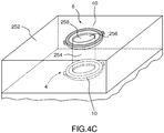
- the first spacer is a bulky layer 252 made of a rigid insulating material and pierced perpendicularly to the layer plane with at least one longitudinal hole(s), here a single longitudinal hole 254, at a predetermined location 256.
- the predetermined location 256 is determined so that the longitudinal hole 254 opens at one end to a central opening 258 of the second track 40 of the first magnetic field transmitter 6, when the second track 40 of the first transmitter 6 has such a central opening 258 and when the first spacer and the first magnetic field transmitter are integrated.
- the rigid insulating material of the first spacer is comprised among the dioxide of silicon SiO 2 .
- the thickness e 12 of the insulating layer of the first spacer is ranging from 1 ⁇ m to 5 ⁇ m, or from 600 nm to 1 ⁇ m, or from 200 nm to 600 nm, or from 50 nm to 200 nm, or from 10 nm to 50 nm, or from 1 nm to 10 nm.
- the material of the first track is a magneto-resistive material among the bi-layer structure material, in particular Ta/NiFe/IrMn/Ta, a tri-layer structure material including a ferromagnetic film, a metal and an anti-ferromagnetic film, in particular Ta/NiFe/Cu/IrMn/Ta, and a spin-valve structure material, in particular Ta/NiFe/Cu/NiFe/IrMn/Ta; and the material of the second track is a magneto-resistive material among a bi-layer structure material, in particular Ta/NiFe/IrMn/Ta, a tri-layer structure material including a ferromagnetic film, a metal and an anti-ferromagnetic film, in particular Ta/NiFe/Cu/IrMn/Ta, and a spin-valve structure material, in particular Ta/NiFe/Cu/
- the accuracy of the alignment of the axis before their rotation is below 10 nm and the accuracy of the set ⁇ angle is below 1,0 degree, preferably below 0, 02 degree.
- the magnetic field receiver 4 and the first magnetic field transmitter 5 are identical, or the magnetic field receiver 4 and the first magnetic field transmitter 6 mutually differ by the shape of their magnetic track, and/or the material of their electromagnetic track.
- a magnetic measuring system 262 comprises the magnetic hybrid AMR/PHR based sensing device 2 as described in the Figures 1A-1B , and a voltage measurement device 264 connected between the first and second voltage terminals.
- the magnetic measuring system 262 is configured for keeping disconnected the first pair of current terminals 14, 16 of the magnetic field receiver 4, the second pair of current terminals 44, 46 of the first magnetic field transmitter 6, and the second pair of voltage terminals 54, 56 so that the impedance between the first pair of current terminals 14, 16, the impedance between the second pair of current terminals 44, 46, the impedance between the second pair of voltage terminals are representative of open circuits.
- the voltage measurement device 264 comprises an amplifier circuit, connected to the first and second voltage terminals, for amplifying a measurement signal and/or cancelling an offset voltage from the said measurement signal.
- the amplifier is integrated within the magnetic sensing device 2.
- the magnetic measuring system 262 is well suited to measure local magnitude and/or variation of a time varying magnetic field, generated remotely or closely by one or several magnetic source(s) and to implement the magnetic measuring method according to the invention as described in the Figure 5B .
- a magnetic measuring method 302 comprises a first set of steps for measuring local magnitude and/or variation of a magnetic field generated remotely or closely by one or several magnetic source(s).
- a magnetic hybrid AMR/PHR based sensing device as described here above in the Figures 1A-1C and 4A-4C .
- the sensing device comprises a magnetic field receiver and a first magnetic field transmitter as described here above.
- a differential voltage V MR between the voltage terminals of the first pair is measured by a voltage measurement device connected between the first and second voltage terminals, while keeping disconnected the first pair of current terminals of the magnetic field receiver, the first pair of voltage terminals of the magnetic field receiver, and the second pair of current terminals of the first magnetic field transmitter, so that the impedance between the first pair of current terminals, the impedance between the first pair of voltage terminals, the impedance between the second pair of current terminals are representative of open circuits.
- a local magnitude and/or variation of a time varying magnetic field, generated remotely or closely by one or several magnetic source(s), is determined on the basis of the measured differential voltage.
- a magnetic measuring system 322 comprises the magnetic hybrid MR/PHR based sensing device 2 as described in the Figures 1A-1B , one second track current source 324 for supplying a DC and/or AC current to the second track 40 of the first magnetic field transmitter 6 and a voltage measurement device 334, similar to the voltage measurement device 264 of the Figure 5A and connected between the first pair of voltage terminals 24, 26.
- the magnetic measuring system 322 is configured for keeping disconnected the first pair of current terminals 14, 16 of the magnetic field receiver 4, the second pair of voltage terminals 54, 56 so that the impedance between the first pair of current terminals 14, 16, the impedance between the second pair of voltage terminals 54, 56 are representative of open circuits.
- the voltage measurement device 334 comprises an amplifier circuit, connected to the first and second voltage terminals 24, 26, for amplifying a measurement signal and/or cancelling an offset voltage from the said measurement signal.
- the amplifier is integrated within the magnetic sensing device 2.
- the first spacer 342 is similar to a spacer among the described spacers of Figure 4A, 4B and 4C .
- Such a spacer 342 is configured to drive magnetic particles 348 in the vicinity and close to an active area of the magneto-resistive track 10 of the magnetic field receiver 4.
- the magnetic measuring system 322 is well suited to measure local magnitude and/or variation of a magnetic field, generated closely by one or several magnetic particles and to implement a magnetic measuring method according to a second method embodiment described in Figure 6B .
- the magnetic particles to be detected by the magnetic sensing device according to the invention are comprised in the family of:
- a magnetic measuring method 352 comprises a second set of steps for measuring local magnitude and/or variation of a magnetic field generated closely by one or several magnetic source(s).
- a magnetic hybrid AMR/PHR based sensing device 2 as described in the Figures 1A-1C and 4A-4C .
- the sensing device comprises a magnetic field receiver and a first magnetic field transmitter as described here above as well as a first spacer similar to one of the spacers of Figure 4A to 4C .
- a bias DC and/or AC current is injected in the electromagnetic second track 40 of the first magnetic field transmitter 6 by using an electrical bias current source connected between the third and fourth current terminals of the first magnetic field transmitter.
- a set of one or several magnetic particles sensitive to a magnetic field are driven in the vicinity or in contact of an active area of the magneto-resistive track of the magnetic field receiver, the active area being located under the electromagnetic second track of the first magnetic field transmitter.
- a differential voltage V MR between the first and second voltage terminals 24, 26 of the magnetic field receiver 4 is measured by a voltage measurement device connected between the first and second voltage terminals, while keeping disconnected the first pair of current terminals 14, 16 of the magnetic field receiver and the second pair of voltage terminals 54, 56 of the first magnetic field transmitter so that the impedance between the first pair of current terminals 14, 16, and the impedance between the second pair of voltage terminals 54, 56 are representative of open circuits.
- a local magnitude and/or variation of a magnetic field generated closely by the magnetic particles is determined on the basis of the measured differential voltage V MR .
- a magnetic hybrid MR/PHR based sensing device 402 comprises the same following components of the magnetic sensing device 2 of Figures 1A-1B : the magnetic field receiver 4, the first magnetic field transmitter 6, the first spacer 62, the passivation layer 60, and the substrate 8.
- the magnetic field receiver 4, the first magnetic field transmitter 6 and the first spacer 62 of the magnetic sensing device 402 according the second device embodiment are also arranged in the same way as for the magnetic sensing device 2 of Figures 1A-1B according to the first embodiment.
- the magnetic sensing device 402 according to the second embodiment differs from the magnetic sensing device 2 according to the first embodiment in that it comprises further a second magnetic field transmitter 406 as a third component.
- the second magnetic field transmitter 406 is configured for being excited by a DC and/or AC supplied bias current or by an external magnetic field to be measured, and includes:
- the first magnetic field transmitter 6 and the second magnetic field transmitter 406 are identical.
- the first magnetic field transmitter 6, the magnetic field receiver 4 and the second magnetic field transmitter 406 are superimposed and mutually secured through the first spacer 62 and a second spacer 462 so that the field magnetic receiver 4 is sandwiched between the first field magnetic transmitter 6 and the second field magnetic transmitter 106.
- the second insulating spacer 462 is configured to secure the second magnetic field transmitter 406 to the magnetic field receiver 4 on the opposite side of the first insulating spacer 62, once performed an alignment of the respective first easy axis 18 and the first hard axis 28 to the respective third easy axis 448 and the third hard axis 458, followed by a rotation of the said third axis 448, 458 from the said first axis 18, 28 about the common perpendicular axis 464 at the same predetermined fixed offset angle ⁇ of the Figures 1A-1D , and is configured to maintain this axis arrangement as well as a fixed separation distance e 13 between the first track 10 and the third track 440 equal to the fixed separation distance e 12 between the first track and the second track.
- the second spacer 462 is a bulky homogeneous layer made of the same rigid insulating material as the insulating material of the first spacer 62.
- the whole sandwich structure formed by the second magnetic field transmitter 406, the second spacer 462, the magnetic field receiver 4, the first spacer 62, the first magnetic field transmitter and the optional passivation layer, is supported by the substrate 8 through the second magnetic field transmitter 6 and the second spacer 462.
- the magnetic sensing device 402 can be used in a differential mode to detect with a high sensitivity the variation of the magnetic field close to the surface of the first track of the magnetic field receiver when magnetic particles are driven close to and above the said surface in Figure 8 .
- the tracks 40, 440 of the magnetic field transmitters can be only low resistive track made of a material such as copper, aluminum, gold or silver for example to enhance magnetic field.
- a magnetic measuring system 502 comprises the magnetic hybrid MR/PHR based sensing device 402 as described in the Figures 7A-7B , a second track current source 524 and a third track current source 526 for supplying a DC and/or AC current respectively to the second track 40 of the first magnetic field transmitter 6 and the third track 440 of the second magnetic field transmitter 406, and a voltage measurement device 534, similar to the voltage measurement devices 264, 334 of the Figures 5A and 6A and connected between the first pair of voltage terminals 24, 26.
- the magnetic measuring system 502 is configured for keeping disconnected the first pair of current terminals 14, 16 of the magnetic field receiver 4, the second pair of voltage terminals 54, 56, and the third pair of voltage terminals 454, 456, so that the impedance between the first pair of current terminals 14, 16, the impedance between the second pair of voltage terminals 54, 56, the impedance between the third pair of voltage terminals 454, 456 are representative of open circuits.
- the second track current source 524 and the third track current source 526 are configured and connected to the second track of the first magnetic field transmitter and to the third track of the second magnetic field transmitter in order to generate two magnetic fields, symmetric to the plane of the magnetic field receiver and polarized with opposite direction.
- the voltage measurement device 434 comprises an amplifier circuit, connected to the first and second voltage terminals 24, 26, for amplifying a measurement signal and/or cancelling an offset voltage from the said measurement signal.
- the amplifier is integrated within the magnetic sensing device 402.
- first spacer 462 is similar to a spacer among the described spacers of Figure 4A, 4B and 4C .
- Such a spacer 462 is configured to drive magnetic particles 508 in the vicinity and close to an active area of the magneto-resistive track 10 of the magnetic field receiver 4.
- the magnetic measuring system 502 is well suited to measure local magnitude and/or variation of a magnetic field, generated closely by one or several magnetic particles and to implement a magnetic measuring method according to a third method embodiment described in Figure 9B .
- the magnetic particles that can be detected by the third magnetic measuring system are the same magnetic particles that can be detected by the magnetic measuring system of Figure 6A and are listed in description of the Figure 6A .
- a magnetic measuring method 582 comprises a third set of steps for measuring local magnitude and/or variation of a magnetic field generated closely by one or several magnetic source(s).
- a magnetic hybrid AMR/PHR based sensing device 402 according to the second device embodiment as described in the Figures 7A-7B is provided.
- the magnetic sensing device 402 comprises a magnetic field receiver 4, a first magnetic field transmitter 6 and a second magnetic field transmitter 406.
- the magnetic sensing device 402 is configured to operate in a differential mode.
- a bias DC and/or AC current is injected in the second electromagnetic track of the first magnetic field transmitter and in the third magnetic track of the second magnetic field transmitter by using an electrical bias current source, connected between the third and fourth current terminals of the first magnetic field transmitter and between the fifth and the sixth current terminals of the second magnetic field transmitter, so that the excitation magnetic fields generated by the first magnetic field transmitter and the second magnetic field transmitter are polarized on opposite direction.
- a set of one or several magnetic particles sensitive to a magnetic field are driven in the vicinity or in contact of an active area of the magnetic receiver 4 located under the electromagnetic track 40 of the first magnetic field transmitter 6.
- a differential voltage V MR between the first and second voltage terminals 24, 26 of the magnetic field receiver 4 is measured by a voltage measurement device, connected between the first and second voltage terminals 24, 26, while keeping disconnected the first pair of current terminals of the magnetic field receiver and the second pair of voltage terminals of the first magnetic field transmitter so that the impedance between the first pair of current terminals, and the impedance between the second pair of voltage terminals are representative of an open circuit;
- a local magnitude and/or a variation of a time varying magnetic field generated closely by the magnetic particles are determined on the basis of the measured differential voltage V MR .
- the sensing device, the magnetic measuring system, the magnetic measuring method according to the various embodiments as described here above can be used to detect and quantify a known time varying (in particular AC) magnetic field source or to detect an unknown time varying (in particular AC) magnetic field from other noise sources. There is no need to drive an electric power to the magneto-resistive AMR/HR sensor for detecting the time varying magnetic field.
- the use of the sensing device according to the invention can be broadened up to many fields of application requiring low power consumption sensing devices such as robotic and space applications.
- the magnetic field receiver is used to detect the presence of the gas through a magnetic field change caused the magnetic particle(s) deposited on the sensing surface of its AMR/PHR track, while the first magnetic field transmitter is configured to generate the magnetic field.
- the magnetic field receiver operating as a detector detects the magnetic field signal without need of a power supply and generating an undesired thermal noise caused by a resistive Joule effect.
- the sensing device of the invention permits a decrease of its power consumption while detecting a local magnetic field with high sensitivity.
- new applications are rendered possible to AMR/PHR sensors requiring low power consumption.
- the magnetic field sensing device according to the invention can be used for following applications:
- the sensing device is a low power consumption, small and compact device by saving the weight of the power stage supply and by allowing an operation at temperatures ranging from 4°K to 400°K.
- the sensing device operates within large frequency range from 1 to 10 kHz without Joule effect dissipation and any heating process.
- the sensing device according to the invention is less bulky than the conventional inductance of flux gate.
- the size of the sensing device is the order of the micrometer for the AMR/PHR itself and the order of the cm 3 for the packaging.
- the magnetic sensing device of the invention is easy to manufacture, which permits a low cost production rate for a mass production.
Landscapes
- Physics & Mathematics (AREA)
- Condensed Matter Physics & Semiconductors (AREA)
- General Physics & Mathematics (AREA)
- Measuring Magnetic Variables (AREA)
Abstract
Description
- The present invention concerns a magnetic measurement device and a system based on an ultrasensitive Planar Hall magneto-resistive sensor for measuring locally a time varying magnetic free field generated remotely by one or several magnetic source(s) or for measuring tiny quantities of magnetic particles deposited closely to the sensor.
- The invention also relates to a method using the magnetic measurement device and system according to the invention for measuring locally an alternative magnetic free field or for measuring locally a time varying magnetic free field generated remotely by one or several magnetic source(s) or for measuring tiny quantities of magnetic particles deposited closely to the sensor.
- Various detection methods with magneto-resistive (MR) sensors have been proposed to detect local magnitude and/or variation of a magnetic field generated remotely or closely by one or several magnetic source(s) as for example magnetic micro- nanobeads.
- These methods use different types of MR sensors, such as semiconductor Hall sensor, anisotropic magnetoresistive (AMR), giant magnetoresistive (GMR), tunneling magnetoresistive (TMR) and giant magneto-impedance (GMI) sensors.
- These sensors are able to detect small quantities of magnetic particles and/or concentrations of these magnetic particles and described in several papers.
- As an alternative to the MR sensors described here above, the use of Planar Hall Magnetoresistive (PHR) sensors has been also proposed in order to detect lower quantities of magnetic particles and such sensors are described in the patent
WO 2014/009516 A1 . - The Planar Hall Magnetoresistive (PHR) sensors are Anisotropic Magneto Resistance (AMR) coupled with planar Hall effect (PHE) sensors that present a linear dependence as a function of small external field, a very high sensitivity and a high signal-to-noise ratio. These sensors are a growing center of interest in the domain of local magnetic field detection of micro- nano-beads and particularly in the field of magnetic phase transition of bi-stable nano-particles.
- However the Hall Magnetoresistive sensors as described in the cited patents still need a relatively high power external biasing field, thus precluding most low power portable battery powered applications.
- A first technical problem is to propose a portable magnetic hybrid AMR/PHR sensing device for detecting local magnitude and/or variation of a magnetic field generated remotely or closely by one or several magnetic source(s) wherein the power consumption is decreased while keeping a high sensitivity.
- A second technical problem is to propose a portable magnetic hybrid AMR/PHR sensing device for detecting local magnitude and/or variation of a magnetic field generated remotely or closely by one or several magnetic source(s) wherein the power consumption is decreased while keeping a high sensitivity and operating at low temperature ranging from 4°K to 400°K.
- A third technical problem is to propose a method for detecting local magnitude and/or variation of a magnetic field generated remotely or closely by one or several magnetic source(s) that uses a portable magnetic hybrid AMR/PHR sensing device with low power consumption while keeping a high measurement sensitivity.
- The invention aims at solving the first, second and third technical problems.
- To this end, the invention relates to a magnetic hybrid AMR/PHR based sensing device for detecting local magnitude and/or variation of a magnetic field generated remotely or closely by one or several magnetic source(s), and comprising a magnetic field receiver, as a first component, having a structure of a magnetic hybrid AMR/PHR sensor and that includes a magnetoresistive first track with a closed loop shape or a cross junction shape; a first pair of current terminals formed with a first current terminal and a second current terminal, facing each other, contacting with the magnetoresistive first track and forming a first easy axis; a first pair of voltage terminals formed with a first voltage terminal and a second voltage terminal, facing each other, contacting with the magnetoresistive first track and forming a first hard axis, orthogonal to the first easy axis.
- The magnetic hybrid AMR/PHR based sensing device is characterized in that it comprises a first magnetic field transmitter as a second component, configured for being excited by a DC and/or AC supplied bias current or by an external magnetic field to be measured and that includes:
- .- a magnetoresistive or low resistive second track with a closed loop shape or a cross junction shape,
- .- a second pair of current terminals formed with a third current terminal and a fourth current terminal, facing each other, contacting with the second track and forming a second easy axis,
- .- a second pair of voltage terminals formed with a third voltage terminal and a fourth voltage terminal, facing each other, contacting with the second track and forming a second hard axis, orthogonal to the second easy axis.
- The magnetic hybrid AMR/PHR based sensing device is also characterized in that the magnetic field receiver and the magnetic field transmitter are superimposed, secured to and separated by a first insulating spacer configured to align respectively the first easy axis and the first hard axis to the second easy axis and the second hard axis, then rotate the said second axis from said first axis at a predetermines fixed offset angle α, and to maintain this axis arrangement as well as a fixed separation distance e12 between the first track and the second track in a range from few micrometers to few nanometers.
- According to further aspects of the invention which are advantageous but not compulsory, the magnetic measurement system might incorporate one or several of the following features, taken in any technically admissible combination:
- .- the first spacer is a rigid structure made of a rigid insulating material having pillars and beams and/ or ribs, having voids filled by an insulating gas or vacuum; or a bulky homogeneous layer made of a rigid insulating material; or a bully layer made of a rigid insulating material and pierced with at least one longitudinal hole(s), directed along a direction included in the extension plane of the layer, to drive magnetic particle(s) and without lateral opening; or a bulky layer made of a rigid insulating material and pierced with at least one longitudinal hole(s), directed along a direction included in the extension plane of the layer, to drive magnetic particle(s), the longitudinal hole(s) having lateral(s) opening connected to secondary longitudinal hole(s) to provide a control access for controlling a magnetic state of the particle(s); or a bulky layer made of a rigid insulating material and pieced perpendicularly to the layer plane with at least one longitudinal hole(s), when the second track of the first transmitter has a central opening;
- .- the rigid insulating material of the first spacer is comprised among the dioxide of silicon SiO2, and/or the thickness e12 of the insulating layer of the first spacer is ranging from 1 µm to 5 µm, or from 600 nm to 1 µm, or from 200 nm to 600 nm, or from 50 nm to 200 nm, or from 10 nm to 50 nm, or from 1 nm to 10 nm;
- .- the shape of the track of the magnetic field receiver and the shape of the track of the first magnetic field transmitter are shapes comprised in the set of the closed loop shapes among the shapes of a ring junction, a multi-ring junction, an oval junction, a multi-oval junction, a diamond junction, a multi-diamond junction, a square junction, a multi-square junction, a rectangular junction, a multi-rectangular junction, and the shape of a cross junction;
- .- the material of the first track is a magneto-resistive material among the bi-layer structure material, in particular Ta/NiFe/IrMn/Ta, a tri-layer structure material including a ferromagnetic film, a metal and an anti-ferromagnetic film, in particular Ta/NiFe/Cu/IrMn/Ta, and a spin-valve structure material, in particular Ta/NiFe/Cu/NiFe/IrMn/Ta; and the material of the second track is a magneto-resistive material among a bi-layer structure material, in particular Ta/NiFe/IrMn/Ta, a tri-layer structure material including a ferromagnetic film, a metal and an anti-ferromagnetic film, in particular Ta/NiFe/Cu/IrMn/Ta, and a spin-valve structure material, in particular Ta/NiFe/Cu/NiFe/IrMn/Ta, or is a low resistive material among gold, copper and silver metals;
- .- the offset angle α formed between the first easy axis of the magnetic field receiver and the second easy axis of the first field transmitter is selected in the range [0 degree, 90 degrees] so that the sensitivity of the sensing device is maximal, and preferably is comprised within the range [15 degrees, 25 degrees];
- .- the accuracy of the alignment of the axis before their rotation is below 10 nm, and the accuracy of the set α angle is below 1.0 degree, preferably below 0.02 degree;
- .- the magnetic field receiver and the first magnetic field transmitter are identical, or the magnetic field receiver and the first magnetic field transmitter mutually differ by the shape of their electromagnetic track, and/or the material of their electromagnetic track;
- .- the magnet hybrid AMR/PHR based sensing device comprises further a second magnetic field transmitter as a third component, configured for being excited by a DC and/or AC supplied bias current or by an external magnetic field to be measured and that includes: a magnetoresistive or low resistive third track with a closed loop shape or a cross junction shape, a third pair of current terminals formed with a fifth current terminal and a sixth current terminal, facing each other, contacting with the third track and forming a third easy axis, a third pair of voltage terminals formed with a fifth voltage terminal and a sixth voltage terminal, facing each other, contacting with the third track and forming a third hard axis, orthogonal to the third easy axis; and the first magnetic field transmitter and the second magnetic field transmitter are identical; and the first magnetic field transmitter, the magnetic field receiver and the second magnetic field transmitter are superimposed and mutually secured through the first spacer and a second spacer so that the field magnetic receiver is sandwiched between the first field magnetic transmitter and the second field magnetic transmitter;
- .- the second insulating spacer is configured to secure the second magnetic field transmitter to the magnetic field receiver on the opposite side of the first insulating spacer, once an alignment of the respective first easy axis and the first hard axis to the respective third easy axis and the third hard axis, followed by a rotation of the said third axis from the said first axis at the predetermined fixed offset angle α, and to maintain this axis arrangement as well as a fixed separation distance e13 between the first track and the third track equal to the fixed separation distance e12 between the first track and the second track; and the second spacer is a bulky homogeneous layer made of the rigid insulating material as the insulating material of the first spacer;
- .- the magnetic hybrid MR/PHR based sensing device comprises further: either a single second track current source for supplying a DC and/or AC current to the second track of the first magnetic field transmitter when the magnetic sensing device comprises the magnetic field receiver and the first magnetic field transmitter as a single magnetic field transmitter; or a second track current source and a third track current source for supplying a DC and/or AC current respectively to the second track of the first magnetic field transmitter and to the third track of the second magnetic field transmitter when the magnetic sensing device comprises the magnetic field receiver and two first and second magnetic field transmitter to operate in a differential mode, the second track current source and the third track current source being configured and connected to the second track of the first magnetic field transmitter and to the third track of the second magnetic field transmitter in order to generate two magnetic fields, symmetric to the plane of the magnetic field receiver and polarized with opposite direction;
- .- the magnetic hybrid AMR/PHR based sensing device comprises further an amplifier circuit connected to the first and second voltage terminals for amplifying a measurement signal and/or cancel a offset voltage from the said measurement signal.
- The invention also relates to a magnetic measurement method for measuring local magnitude and/or variation of a magnetic field generated remotely or closely by one or several magnetic source(s) according to a first embodiment. The magnetic measuring method comprises the steps of :
- providing a magnetic hybrid AMR/PHR based sensing device comprising a magnetic field receiver and a first magnetic field transmitter as defined here above;
- measuring a differential voltage VMR between the voltage terminals of the first pair by using a voltage measurement device connected between the first and second voltage terminals, while keeping disconnected the first pair of current terminals of the magnetic field receiver, the first pair of voltage terminals of the magnetic field receiver, and the second pair of current terminals of the first magnetic field transmitter so that the impedance between the first pair of current terminals, the impedance between the first pair of voltage terminals, the impedance between the second pair of current terminals are representative of an open circuit;
- determining a local magnitude and/or variation of a time varying magnetic field generated remotely or closely by one or several magnetic source(s) on the basis of the measured differential voltage.
- According to a second embodiment, the invention also relates to a magnetic measurement method for measuring local amplitude and/or variation of a magnetic field generated by one or several magnetic source(s). The magnetic measuring method comprises the steps of :
- providing a magnetic hybrid AMR/PHR based sensing device comprising a magnetic field receiver and a first magnetic field transmitter as defined here above,
- injecting a bias DC and/or AC current in the second magnetic track of the first magnetic field transmitter by using an electrical bias current source connected between the third and fourth current terminals of the first magnetic field transmitter, and
- driving a set of one or several magnetic particles sensitive to a magnetic field in the vicinity or in contact of an active area of the magnetic receiver located under the magnetic track of the first magnetic field transmitter; then
- measuring a differential voltage VMR between the first and second voltage terminals of the magnetic field receiver by using a voltage measurement device connected between the first and second voltage terminals, while keeping disconnected the first pair of current terminals of the magnetic field receiver and the second pair of voltage terminals of the first magnetic field transmitter so that the impedance between the first pair of current terminals, and the impedance between the second pair of voltage terminals are representative of an open circuit;
- determining a local magnitude and/or variation of a time varying magnetic field generated closely by the magnetic particles on the basis of the measured differential voltage.
- According to a third embodiment, the invention also relates to a magnetic measurement method for measuring local amplitude and/or variation of a magnetic field generated by one or several magnetic source(s). The magnetic measuring method comprising the steps of:
- providing a magnetic hybrid AMR/PHR based sensing device comprising a magnetic field receiver, a first magnetic field transmitter and a second magnetic field transmitter as defined here above,
- injecting a bias DC and/or AC current in the second magnetic track of the first magnetic field transmitter and the third magnetic track of the second magnetic field transmitter by using an electrical bias current source connected between the third and fourth current terminals of the first magnetic field transmitter and between the fifth and the sixth current terminals of the second magnetic field transmitter so that the excitation magnetic fields generated by the first magnetic field transmitter and the second magnetic field transmitter are polarized on opposite direction, and
- driving a set of one or several magnetic particles sensitive to a magnetic field in the vicinity or in contact of an active area of the magnetic receiver located under the magnetic track of the first magnetic field transmitter; then
- measuring a differential voltage VMR between the first and second voltage terminals of the magnetic field receiver by using a voltage measurement device connected between the first and second voltage terminals, while keeping disconnected the first pair of current terminals of the magnetic field receiver and the second pair of voltage terminals of the first magnetic field transmitter so that the impedance between the first pair of current terminals, and the impedance between the second pair of voltage terminals are representative of an open circuit;
- determining a local magnitude and/or variation of a time varying magnetic field generated closely by the magnetic particles on the basis of the measured differential voltage.
- The invention will be better understood on the basis of the following description which is given in correspondence with the annexed figures and as an illustrative example, without restricting the object of the invention. In the annexed figures:
-
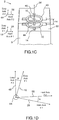
Figures 1A, 1B ,1C and 1D are respectively an exploded view and an integrated view of a magnetic hybrid AMR/PHR based sensing device according to a first embodiment of the invention wherein a magnetic field receiver and a magnetic field transmitter are used, a simplified view of the same sensing device highlighting the main components of the sensing, and an exemplary illustration of an offset angle α between the magnetic field receiver and the magnetic field transmitter; -
Figures 2A ,2B, and 2C are respectively a first view illustrating an experimental set up testing the behavior of the magnetic hybrid AMR/PHR based sensing device according to the first embodiment ofFigures 1A-1B , a second view of the evolution of the detected local magnetic field by the magnetic field receiver versus a known driven AC field while applying different bias currents onto the first and second current terminals of the magnetic field receiver, and a third view of the co-evolution versus time of the measured voltage VMR by the sensing device and a driven voltage applied to the Helmholtz coils following a time varying triangular waveform ; -
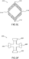
Figures 3A to 3F are views illustrating variant shapes of the electromagnetic track of the magnetic field receiver as shown inFigures 1A-1B , respectively a multi-ring shape, an oval shape, a square shape, a diamond shape, a multi-diamond shape, and a cross junction shape; -
Figures 4A to 4C are views illustrating exemplary variants of the first spacer as shown, respectively a layer with pierced longitudinal holes to drive magnetic particles, a layer with a single pierced longitudinal hole to drive magnetic particles and a lateral hole pierced to access the single hole and permit a control of the magnetic state of the particle(s), and a layer with a perpendicular access hole extending perpendicularly from a central void area of a first magnetic field transmitter; - Figured 5A and 5B are respectively a view of a magnetic measurement system according to a first system embodiment using a sensing device according to the first sensing device embodiment of
Figure 1B and configured to implement a magnetic measurement method according to a first method embodiment, and a flow chart magnetic measurement method according to the first method embodiment; - Figured 6A and 6B are respectively a view of a magnetic measurement system according to a second system embodiment using a sensing device according to the first sensing device embodiment of the invention with a first spacer as shown in
Figures 4A-4C and configured to implement a magnetic measurement method according to a second method embodiment, and a flow chart magnetic measurement method according to the second method embodiment; -
Figures 7A and7B are respectively an exploded view and an integrated view of a magnetic hybrid AMR/PHR based sensing device according to a second sensing device embodiment of the invention where a magnetic field receiver and two magnetic field transmitters are used; -
Figure 8 is schematic view illustration the differential mode operation of the sensing device ofFigures 7A and7B ; -
Figures 9A and9B are respectively a view of a magnetic measurement system according to a third system embodiment using a sensing device according to the second sensing device embodiment ofFigure 7B and configured to implement a magnetic measurement method according to a third method embodiment, and a flow chart magnetic measurement method according to the third method embodiment. - According to
Figures 1A, 1B and1C and a first device embodiment of the invention, a magnetic hybrid AMR/PHR basedsensing device 2 is configured for detecting local magnitude and/or variation of a magnetic field generated remotely or closely by one or several magnetic source(s). - The
magnetic sensing device 2 comprises amagnetic field receiver 4 as a first component and a firstmagnetic field transmitter 6 as a second component, and asubstrate 8 serving as support of the set formed by themagnetic field receiver 4 and the firstmagnetic field transmitter 6. - The
magnetic field receiver 4 has a structure of a magnetic hybrid AMR/PHR sensor and includes: - a magneto-resistive
first track 10 with a closed loop shape or a cross junction shape, here a magneto-resistive single ring, - a
first pair 12 ofcurrent terminals current terminal 14 and a secondcurrent terminal 16, facing each other, contacting with the magneto-resistivefirst track 8 and forming a firsteasy axis 18, - a
first pair 22 ofvoltage terminals first voltage terminal 24 and asecond voltage terminal 26, facing each other, contacting with the magneto-resistivefirst track 10 and forming a firsthard axis 28, orthogonal to the firsteasy axis 18. - The first
magnetic field transmitter 6 is configured for being excited by a DC and/or AC current supplied by a bias current generator or by a time varying external magnetic field to be measured, and includes: - a magneto-resistive or low resistive
second track 40 with a closed loop shape or a cross junction shape, - a
second pair 42 ofcurrent terminals current terminal 44 and a fourthcurrent terminal 46, facing each other, contacting with thesecond track 40 and forming a secondeasy axis 48, - a
second pair 52 ofvoltage terminals third voltage terminal 54 and afourth voltage terminal 56, facing each other, contacting with thesecond track 40 and forming a secondhard axis 58, orthogonal to the secondeasy axis 48. - The
second track 40 of the first magnetic field transmitter is covered by apassivation layer 60. - The
magnetic field receiver 4 and the firstmagnetic field transmitter 6 are superimposed, secured to and separated by a first insulatingspacer 62 configured to align respectively the firsteasy axis 18 and the firsthard axis 28 to the secondeasy axis 48 and the secondhard axis 58, then rotate the saidsecond axis first axis perpendicular axis 64 at a predetermined fixed offset angle α, and to maintain this axis arrangement as well as a fixed separation distance e12 between thefirst track 6 and thesecond track 8 in a range from few micrometers to few nanometers. - Here, in the
Figures 1A and 1B the value of the predetermined offset angle α is assumed equal to zero. - More generally, the offset angle α formed between the firs
easy axis 18 and the second easy axis, or equivalently between the firsthard axis 28 and the secondhard axis 58 is selected in the range [0 degree, 90 degree] so that the sensitivity of the magnetic sensor is maximal, and preferably is comprised within the range [15 degree, 25 degree] as shown in theFigure 1D . - According to the
Figure 1D , the offset angle α that optimizes themagnetic sensing device 2 is assumed to be equal 20 degrees. - According to
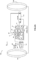
Figure 2A anexperimental system 102 for testing the behavior of the magnetic hybrid AMR/PHR basedsensing device 2 according to the first embodiment ofFigures 1A to 1D comprises a sample unit to be tested 2 as defined inFigures 1A to 1D , a pair ofHelmholtz coils sensing device 2 along the second hard axis of the first magnetic field transmitter, a biascurrent generator 112 to polarize the magnetic field receiver, and ameasurement unit 114 connected to thevoltage terminals magnetic field receiver 4 and locked to a current signal taken at thecurrent terminals track 40 of the firstmagnetic field transmitter 6. - The two
Helmholtz coils voltage generator 118 configured to inject a DC+AC or AC driven current in the Helmholtz coils 16, 108, that can be translated into a driven voltage expressed in volts and ranging from -1.0 V (Volt) to +1.0 V (Volt) on a first abscissa axis in theFigure 2B . - Here, the magnetic field receiver and the first magnetic field transmitter are separated by a passivation layer forming the first spacer, the thickness thereof is comprised within 100nm to 1µm and the diameter of the first magneto-resistive ring track is here equal to 600 µm.
- According to the
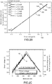
Figure 2B , the evolution of the magneto-resistive voltage VMR, measured by thesensing device 2 between thevoltage terminals track 10 of themagnetic field receiver 4 and expressed in mV (milliVolt) on asecond ordinate axis 134, versus the driven voltage, is plot in aset 138 ofcurves current terminals PHR track 10 of themagnetic receiver 4 respectively equal to 0 mA, 0.1 mA, 0.5 mA, 1 mA, 2 mA and 5 mA. - As shown in the
Figure 2B , the measurements of the sensing voltage VMR achieved by using the test configuration of theFigure 2A , indicate that thecurves PHR track 1 ofmagnetic field receiver 4, the magnetic field receiver forming an actual sensor of a local magnetic field along the first hard axis and the first magnetic field transmitter forming a kind of local magnetic field lens. - Regardless of the intensity of an injected bias current, an alternative AC magnetic field HAC at a given frequency ω induces an alternative current with the same frequency ω for the
receiver 4 of thesensing device 2. The amplitude of the induced current is proportional to the magnitude of the alternative magnetic field HAC. When injecting a bias current into thetrack 10 of thereceiver 4, no increment is observed in the detected voltage signal VMR with the magnitude of the injected bias current but only an increment of the noise through the thermal noise signal component as shown in theFigure 2C . - According to
Figure 2C , a direct DC bias current is injected into the magneto-resistivefirst track 10 of thereceiver 4 through the first and second current terminals and a driven voltage is applied to the Helmholtz coils following a time varyingtriangular waveform 162. The corresponding evolution of the measured voltage VMR versus time t is illustrated by acurve 164. - Accordingly, the
sensing device 2 according the invention is configured to a avoid any injection of a direct DC bias current through the first and second current terminals by implementing an open circuit between the said first and second current terminals through an insulating material. - In such a test configuration it is thus shown that the no bias current need to be injected, which means that the AMR/PHR sensor forming the
magnetic field receiver 4 does not need a power voltage supply to detect a local magnetic field. Accordingly, the magnetic field receiver can detect the induced collimated field generated by the track second track of the first magnetic field transmitter also without any supply power. - Generally, the shape of the magnetic field receiver and the shape of the first magnetic field transmitter are shapes comprised in the set of the closed loop shapes among the shapes of a ring junction, a multi-ring junction, an oval junction, a multi-oval junction, a diamond junction, a multi-diamond junction, a square junction, a multi-square junction, a rectangular junction, a multi-rectangular junction, and the shape of a cross junction.
- As example, a
multi-ring junction 170 is illustrated inFigure 3A with a pair ofcurrent terminals voltage terminals - As example, an
oval junction 180 is illustrated inFigure 3B with a pair ofcurrent terminals voltage terminals - As example, a
square junction 190 is illustrated inFigure 3C with a pair ofcurrent terminals voltage terminals - As example, a
diamond junction 200 is illustrated inFigure 3D with a pair ofcurrent terminals voltage terminals - As example, a
multi-diamond junction 210 is illustrated inFigure 3E with a pair ofcurrent terminals voltage terminals - As example, a
cross junction 220 is illustrated inFigure 3F with a pair ofcurrent terminals voltage terminals - According to the
Figures 1A and 1B the first spacer is a bulky homogeneous layer made of a rigid insulating material. - As a first variant, the spacer is a rigid structure made of a rigid insulating material having pillars and beams and/ or ribs, having voids filled by an insulating gas or vacuum.
- According to the
Figure 4A and as a second variant, the first spacer is abulky layer 232 made of a rigid insulating material and pierced with at least one longitudinal hole(s), here threelongitudinal holes direction 240 included in the extension plane of thelayer 232, to drive magnetic particle(s) and without lateral opening. For example, the direction of the longitudinal holes is chosen so that when the first spacer and the magnetic field receiver are integrated the first hard axis of the magneto-resistive first track and the extension direction of the longitudinal holes are parallel. - According to the
Figure 4B and as a third variant, the first spacer is abulky layer 242 made of a rigid insulating material and pierced with at least one longitudinal hole(s), here a singlelongitudinal hole 244, directed along a direction 246 included in the extension plane of the layer, to drive magnetic particle(s). The longitudinal hole(s), here thesingle hole 244, have/has lateral(s) opening, here onelateral opening 248, connected to secondary longitudinal hole(s), here one se secondarylongitudinal hole 250 in theFigure 4B , to provide a control access for controlling a magnetic state of the particle(s). - According to the
Figure 4C and a fourth variant, the first spacer is abulky layer 252 made of a rigid insulating material and pierced perpendicularly to the layer plane with at least one longitudinal hole(s), here a singlelongitudinal hole 254, at apredetermined location 256. Thepredetermined location 256 is determined so that thelongitudinal hole 254 opens at one end to acentral opening 258 of thesecond track 40 of the firstmagnetic field transmitter 6, when thesecond track 40 of thefirst transmitter 6 has such acentral opening 258 and when the first spacer and the first magnetic field transmitter are integrated. - According to the
Figures 1A-1C and4A-4C , the rigid insulating material of the first spacer is comprised among the dioxide of silicon SiO2. - The thickness e12 of the insulating layer of the first spacer is ranging from 1 µm to 5 µm, or from 600 nm to 1 µm, or from 200 nm to 600 nm, or from 50 nm to 200 nm, or from 10 nm to 50 nm, or from 1 nm to 10 nm.
- According to the
Figures 1A-1C and4A-4C , the material of the first track is a magneto-resistive material among the bi-layer structure material, in particular Ta/NiFe/IrMn/Ta, a tri-layer structure material including a ferromagnetic film, a metal and an anti-ferromagnetic film, in particular Ta/NiFe/Cu/IrMn/Ta, and a spin-valve structure material, in particular Ta/NiFe/Cu/NiFe/IrMn/Ta; and
the material of the second track is a magneto-resistive material among a bi-layer structure material, in particular Ta/NiFe/IrMn/Ta, a tri-layer structure material including a ferromagnetic film, a metal and an anti-ferromagnetic film, in particular Ta/NiFe/Cu/IrMn/Ta, and a spin-valve structure material, in particular Ta/NiFe/Cu/NiFe/IrMn/Ta, or is a low resistive material among gold, copper and silver metals. - The accuracy of the alignment of the axis before their rotation is below 10 nm and the accuracy of the set α angle is below 1,0 degree, preferably below 0, 02 degree.
- Generally, the
magnetic field receiver 4 and the firstmagnetic field transmitter 5 are identical, or themagnetic field receiver 4 and the firstmagnetic field transmitter 6 mutually differ by the shape of their magnetic track, and/or the material of their electromagnetic track. - According to
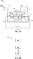
Figure 5A and a first embodiment, amagnetic measuring system 262 comprises the magnetic hybrid AMR/PHR basedsensing device 2 as described in theFigures 1A-1B , and avoltage measurement device 264 connected between the first and second voltage terminals. - The
magnetic measuring system 262 is configured for keeping disconnected the first pair ofcurrent terminals magnetic field receiver 4, the second pair ofcurrent terminals magnetic field transmitter 6, and the second pair ofvoltage terminals current terminals current terminals - The
voltage measurement device 264 comprises an amplifier circuit, connected to the first and second voltage terminals, for amplifying a measurement signal and/or cancelling an offset voltage from the said measurement signal. - In a particular embodiment, the amplifier is integrated within the
magnetic sensing device 2. - The
magnetic measuring system 262 is well suited to measure local magnitude and/or variation of a time varying magnetic field, generated remotely or closely by one or several magnetic source(s) and to implement the magnetic measuring method according to the invention as described in theFigure 5B . - According to
Figure 5B and a first method embodiment of the invention, amagnetic measuring method 302 comprises a first set of steps for measuring local magnitude and/or variation of a magnetic field generated remotely or closely by one or several magnetic source(s). - In a
first step 304, a magnetic hybrid AMR/PHR based sensing device as described here above in theFigures 1A-1C and4A-4C , is provided. The sensing device comprises a magnetic field receiver and a first magnetic field transmitter as described here above. - Then in a
second step 306, a differential voltage VMR between the voltage terminals of the first pair is measured by a voltage measurement device connected between the first and second voltage terminals, while keeping disconnected the first pair of current terminals of the magnetic field receiver, the first pair of voltage terminals of the magnetic field receiver, and the second pair of current terminals of the first magnetic field transmitter, so that the impedance between the first pair of current terminals, the impedance between the first pair of voltage terminals, the impedance between the second pair of current terminals are representative of open circuits. - Then in a
third step 308, a local magnitude and/or variation of a time varying magnetic field, generated remotely or closely by one or several magnetic source(s), is determined on the basis of the measured differential voltage. - According to
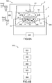
Figure 6A and a second system embodiment, amagnetic measuring system 322 according to the invention comprises the magnetic hybrid MR/PHR basedsensing device 2 as described in theFigures 1A-1B , one second trackcurrent source 324 for supplying a DC and/or AC current to thesecond track 40 of the firstmagnetic field transmitter 6 and avoltage measurement device 334, similar to thevoltage measurement device 264 of theFigure 5A and connected between the first pair ofvoltage terminals - The
magnetic measuring system 322 is configured for keeping disconnected the first pair ofcurrent terminals magnetic field receiver 4, the second pair ofvoltage terminals current terminals voltage terminals - The
voltage measurement device 334 comprises an amplifier circuit, connected to the first andsecond voltage terminals - In a particular embodiment, the amplifier is integrated within the
magnetic sensing device 2. - Moreover, here the
first spacer 342 is similar to a spacer among the described spacers ofFigure 4A, 4B and4C . Such aspacer 342 is configured to drivemagnetic particles 348 in the vicinity and close to an active area of the magneto-resistive track 10 of themagnetic field receiver 4. - The
magnetic measuring system 322 is well suited to measure local magnitude and/or variation of a magnetic field, generated closely by one or several magnetic particles and to implement a magnetic measuring method according to a second method embodiment described inFigure 6B . - The magnetic particles to be detected by the magnetic sensing device according to the invention are comprised in the family of:
- .- any switchable molecular nanoparticles in form of AhBk[M(CN)6]l.mH2O, where A can be Co, Ni, Fe, etc, B and M can be various transition metals (FeII, FeIII, MnII, MnIII, CoII, CoIII, NiII, NiIII...);
- .- any Hoffman clathrate switchable molecular nanoparticles in form of FeII(A)[MII(CN)4].nH2O, where A is the ligand field (pz, azpy,...) and MII is a metallic ion (Ni, Pd, and Pt);
- .- any spin crossover nanoparticles of triazole family: [Fe(hptrz)3]OTs)2.(hptrz=4-heptyl-1,2,4-triazole and OTs=toluenesulfonyl);
- .- any paramagnetic or superparamagnetic particles: Fe2O3, Fe3O4, Fe@Fe3O4, CoFe@Fe3O4, Ni, ...;
- .- any ferromagnetic particles: Fe, CoFe, Ni;
- .- any anti-ferromagnetic particles;
- .- any particles with multilayer structure Ti/Fe, Cr, NiO, Co3O4, a-Fe2O3, CuO, MnO,Cr2O3 nano-particles;
- .- any magnetic bead made of Fe3O4 in the polymer or any amorphous (silica, xerogel, aerogel, ...) matrix with the sphere shape and any size ranging from 50 nm to 10 µm.
- According to
Figure 6B and a second method embodiment of the invention, amagnetic measuring method 352 comprises a second set of steps for measuring local magnitude and/or variation of a magnetic field generated closely by one or several magnetic source(s). - In a
first step 354, a magnetic hybrid AMR/PHR basedsensing device 2, as described in theFigures 1A-1C and4A-4C , is provided. The sensing device comprises a magnetic field receiver and a first magnetic field transmitter as described here above as well as a first spacer similar to one of the spacers ofFigure 4A to 4C . - Then in a
second step 356, a bias DC and/or AC current is injected in the electromagneticsecond track 40 of the firstmagnetic field transmitter 6 by using an electrical bias current source connected between the third and fourth current terminals of the first magnetic field transmitter. - Then in
third step 358, a set of one or several magnetic particles sensitive to a magnetic field are driven in the vicinity or in contact of an active area of the magneto-resistive track of the magnetic field receiver, the active area being located under the electromagnetic second track of the first magnetic field transmitter. - Then in a
fourth step 360, a differential voltage VMR between the first andsecond voltage terminals magnetic field receiver 4 is measured by a voltage measurement device connected between the first and second voltage terminals, while keeping disconnected the first pair ofcurrent terminals voltage terminals current terminals voltage terminals - Then in
fifth step 362, a local magnitude and/or variation of a magnetic field generated closely by the magnetic particles is determined on the basis of the measured differential voltage VMR. - According to
Figures 7A and7B and a second magnetic sensing device embodiment, a magnetic hybrid MR/PHR basedsensing device 402 comprises the same following components of themagnetic sensing device 2 ofFigures 1A-1B : themagnetic field receiver 4, the firstmagnetic field transmitter 6, thefirst spacer 62, thepassivation layer 60, and thesubstrate 8. Themagnetic field receiver 4, the firstmagnetic field transmitter 6 and thefirst spacer 62 of themagnetic sensing device 402 according the second device embodiment are also arranged in the same way as for themagnetic sensing device 2 ofFigures 1A-1B according to the first embodiment. - The
magnetic sensing device 402 according to the second embodiment differs from themagnetic sensing device 2 according to the first embodiment in that it comprises further a secondmagnetic field transmitter 406 as a third component. - The second
magnetic field transmitter 406 is configured for being excited by a DC and/or AC supplied bias current or by an external magnetic field to be measured, and includes: - a magneto-resistive or low resistive
third track 440 with a closed loop shape or a cross junction shape, - a third pair 442 of
current terminals current terminal 444 and a sixthcurrent terminal 446, facing each other, contacting with thethird track 440 and forming a thirdeasy axis 448, - a
third pair 452 ofvoltage terminals third track 440 and forming a third hard axis 458, orthogonal to the thirdeasy axis 448. - The first
magnetic field transmitter 6 and the secondmagnetic field transmitter 406 are identical. - The first
magnetic field transmitter 6, themagnetic field receiver 4 and the secondmagnetic field transmitter 406 are superimposed and mutually secured through thefirst spacer 62 and asecond spacer 462 so that the fieldmagnetic receiver 4 is sandwiched between the first fieldmagnetic transmitter 6 and the second fieldmagnetic transmitter 106. - The second
insulating spacer 462 is configured to secure the secondmagnetic field transmitter 406 to themagnetic field receiver 4 on the opposite side of the first insulatingspacer 62, once performed an alignment of the respective firsteasy axis 18 and the firsthard axis 28 to the respective thirdeasy axis 448 and the third hard axis 458, followed by a rotation of the saidthird axis 448, 458 from the saidfirst axis perpendicular axis 464 at the same predetermined fixed offset angle α of theFigures 1A-1D , and is configured to maintain this axis arrangement as well as a fixed separation distance e13 between thefirst track 10 and thethird track 440 equal to the fixed separation distance e12 between the first track and the second track. - The
second spacer 462 is a bulky homogeneous layer made of the same rigid insulating material as the insulating material of thefirst spacer 62. - The whole sandwich structure formed by the second
magnetic field transmitter 406, thesecond spacer 462, themagnetic field receiver 4, thefirst spacer 62, the first magnetic field transmitter and the optional passivation layer, is supported by thesubstrate 8 through the secondmagnetic field transmitter 6 and thesecond spacer 462. - According to
Figure 8 , amap 472 at a given fixed time of a section of the magnetic field generated by the second magneto-resistive track 40 of the firstmagnetic field transmitter 6 and the third magneto-resistive track 440 of the secondmagnetic field transmitter 406 by a plane P, perpendicular to the extension plane Q of thefirst track 10 of themagnetic field receiver 4 and including theline 476 passing through the third pair of thecurrent terminals line 476 in a reference configuration without magnetic particle(s). - Accordingly the
magnetic sensing device 402 can be used in a differential mode to detect with a high sensitivity the variation of the magnetic field close to the surface of the first track of the magnetic field receiver when magnetic particles are driven close to and above the said surface inFigure 8 . - It should be noted that the
tracks - According to
Figure 9A and a third system embodiment, amagnetic measuring system 502 according to the invention comprises the magnetic hybrid MR/PHR basedsensing device 402 as described in theFigures 7A-7B , a second trackcurrent source 524 and a third trackcurrent source 526 for supplying a DC and/or AC current respectively to thesecond track 40 of the firstmagnetic field transmitter 6 and thethird track 440 of the secondmagnetic field transmitter 406, and avoltage measurement device 534, similar to thevoltage measurement devices Figures 5A and6A and connected between the first pair ofvoltage terminals - The
magnetic measuring system 502 is configured for keeping disconnected the first pair ofcurrent terminals magnetic field receiver 4, the second pair ofvoltage terminals voltage terminals current terminals voltage terminals voltage terminals - The second track
current source 524 and the third trackcurrent source 526 are configured and connected to the second track of the first magnetic field transmitter and to the third track of the second magnetic field transmitter in order to generate two magnetic fields, symmetric to the plane of the magnetic field receiver and polarized with opposite direction. - The voltage measurement device 434 comprises an amplifier circuit, connected to the first and
second voltage terminals - In a particular embodiment, the amplifier is integrated within the
magnetic sensing device 402. - Moreover, here the
first spacer 462 is similar to a spacer among the described spacers ofFigure 4A, 4B and4C . Such aspacer 462 is configured to drivemagnetic particles 508 in the vicinity and close to an active area of the magneto-resistive track 10 of themagnetic field receiver 4. - The
magnetic measuring system 502 is well suited to measure local magnitude and/or variation of a magnetic field, generated closely by one or several magnetic particles and to implement a magnetic measuring method according to a third method embodiment described inFigure 9B . - The magnetic particles that can be detected by the third magnetic measuring system are the same magnetic particles that can be detected by the magnetic measuring system of
Figure 6A and are listed in description of theFigure 6A . - According to
Figure 9B and a third method embodiment, amagnetic measuring method 582 comprises a third set of steps for measuring local magnitude and/or variation of a magnetic field generated closely by one or several magnetic source(s). - In a
first step 584, a magnetic hybrid AMR/PHR basedsensing device 402 according to the second device embodiment as described in theFigures 7A-7B is provided. Themagnetic sensing device 402 comprises amagnetic field receiver 4, a firstmagnetic field transmitter 6 and a secondmagnetic field transmitter 406. Themagnetic sensing device 402 is configured to operate in a differential mode. - Then in a
second step 586, a bias DC and/or AC current is injected in the second electromagnetic track of the first magnetic field transmitter and in the third magnetic track of the second magnetic field transmitter by using an electrical bias current source, connected between the third and fourth current terminals of the first magnetic field transmitter and between the fifth and the sixth current terminals of the second magnetic field transmitter, so that the excitation magnetic fields generated by the first magnetic field transmitter and the second magnetic field transmitter are polarized on opposite direction. - Then in a
third step 588, a set of one or several magnetic particles sensitive to a magnetic field are driven in the vicinity or in contact of an active area of themagnetic receiver 4 located under theelectromagnetic track 40 of the firstmagnetic field transmitter 6. - Then in a fourth step 590 a differential voltage VMR between the first and
second voltage terminals magnetic field receiver 4 is measured by a voltage measurement device, connected between the first andsecond voltage terminals - Then in a
fifth step 592, a local magnitude and/or a variation of a time varying magnetic field generated closely by the magnetic particles are determined on the basis of the measured differential voltage VMR. - The sensing device, the magnetic measuring system, the magnetic measuring method according to the various embodiments as described here above can be used to detect and quantify a known time varying (in particular AC) magnetic field source or to detect an unknown time varying (in particular AC) magnetic field from other noise sources. There is no need to drive an electric power to the magneto-resistive AMR/HR sensor for detecting the time varying magnetic field. The use of the sensing device according to the invention can be broadened up to many fields of application requiring low power consumption sensing devices such as robotic and space applications.
- For the application of gas sensing, the magnetic field receiver is used to detect the presence of the gas through a magnetic field change caused the magnetic particle(s) deposited on the sensing surface of its AMR/PHR track, while the first magnetic field transmitter is configured to generate the magnetic field. The magnetic field receiver operating as a detector detects the magnetic field signal without need of a power supply and generating an undesired thermal noise caused by a resistive Joule effect.
- Accordingly the sensing device of the invention permits a decrease of its power consumption while detecting a local magnetic field with high sensitivity. As a result new applications are rendered possible to AMR/PHR sensors requiring low power consumption.
- As other examples, the magnetic field sensing device according to the invention can be used for following applications:
- detection of underground electrical power line,
- detection of magnetic field generated from magnetization of magnetic materials ranging from deposited nano-particle(s) to bulk magnetic materials;
- scanning geological rock in caves;
- scanning the magnetic domains of (ferro)magnetic materials mapping the self-magnetic field generated by magnetic sensors (AMR/PHR/GMR/Hall/GMI/TMR etc...) ;
- space applications that needs to detect the magnetic field, to save mass and to operate at low temperature.
- Advantageously the sensing device according to the invention is a low power consumption, small and compact device by saving the weight of the power stage supply and by allowing an operation at temperatures ranging from 4°K to 400°K. The sensing device operates within large frequency range from 1 to 10 kHz without Joule effect dissipation and any heating process.
- For the same sensitivity, the sensing device according to the invention is less bulky than the conventional inductance of flux gate. The size of the sensing device is the order of the micrometer for the AMR/PHR itself and the order of the cm3 for the packaging.
- In addition to its light weight the magnetic sensing device of the invention is easy to manufacture, which permits a low cost production rate for a mass production.
Claims (15)
- A magnetic hybrid AMR/PHR based sensing device for detecting local magnitude and/or variation of a magnetic field generated remotely or closely by one or several magnetic source(s), and comprising:- a magnetic field receiver (4), as a first component, having a structure of a magnetic hybrid AMR/PHR sensor and that includes• a magnetoresistive first track (10) with a closed loop shape or a cross junction shape,• a first pair (12) of current terminals formed with a first current terminal (14) and a second current terminal (16), facing each other, contacting with the magnetoresistive first track (10) and forming a first easy axis (18),• a first pair (22) of voltage terminals formed with a first voltage terminal (24) and a second voltage terminal (26), facing each other, contacting with the magnetoresistive first track (10) and forming a first hard axis (28), orthogonal to the first easy axis (18),characterized in that
the magnetic hybrid AMR/PHR based sensing device comprises:- a first magnetic field transmitter (6) as a second component, configured for being excited by a DC and/or AC supplied bias current or by an external magnetic field to be measured and that includes• a magnetoresistive or low resistive second track (40) with a closed loop shape or a cross junction shape,• a second pair (42) of current terminals formed with a third current terminal (44) and a fourth current terminal (46), facing each other, contacting with the second track (40) and forming a second easy axis (48),• a second pair (52) of voltage terminals formed with a third voltage terminal (54) and a fourth voltage terminal (56), facing each other, contacting with the second track (40) and forming a second hard axis (58), orthogonal to the second easy axis (48), and
in that the magnetic field receiver (4) and the magnetic field transmitter (6) are superimposed, secured to and separated by a first insulating spacer (62) configured to align respectively the first easy axis (18) and the first hard axis (28) to the second easy axis (48) and the second hard axis (58), then rotate the said second axis (48, 58) from said first axis (18, 28) at a predetermines fixed offset angle α, and to maintain this axis arrangement as well as a fixed separation distance e12 between the first track (10) and the second track (40) in a range from few micrometers to few nanometers. - The magnetic hybrid AMR/PHR based sensing device according to claim 1, wherein the first spacer (62) is a:- a rigid structure made of a rigid insulating material having pillars and beams and/ or ribs, having voids filled by an insulating gas or vacuum; or- a bulky homogeneous layer made of a rigid insulating material; or- a bully layer (232) made of a rigid insulating material and pierced with at least one longitudinal hole(s) (234, 236, 238), directed along a direction (240) included in the extension plane of the layer, to drive magnetic particle(s) and without lateral opening; or- a bulky layer (242) made of a rigid insulating material and pierced with at least one longitudinal hole(s) (244), directed along a direction (246) included in the extension plane of the layer (242), to drive magnetic particle(s), the longitudinal hole(s) (244) having lateral(s) opening (248) connected to secondary longitudinal hole(s) (250) to provide a control access for controlling a magnetic state of the particle(s); or- a bulky layer (252) made of a rigid insulating material and pieced perpendicularly to the layer plane with at least one longitudinal hole(s) (254), when the second track (40) of the first transmitter (6) has a central opening (258).
- The magnetic hybrid AMR/PHR based sensing device according to any of claims 1 to 2, wherein
the rigid insulating material of the first spacer (62) is comprised among the dioxide of silicon SiO2, and/or
the thickness e12 of the insulating layer of the first spacer (62) is ranging from 1 µm to 5 µm, or from 600 nm to 1 µm, or from 200 nm to 600 nm, or from 50 nm to 200 nm, or from 10 nm to 50 nm, or from 1 nm to 10 nm. - The magnetic hybrid AMR/PHR based sensing device according to any of claims 1 to 3, wherein the shape of the track (10) of the magnetic field receiver (4) and the shape of the track (40) of the first magnetic field transmitter (6) are shapes comprised in the set of the closed loop shapes among the shapes of a ring junction, a multi-ring junction (170), an oval junction (180), a multi-oval junction, a diamond junction (200), a multi-diamond junction (210), a square junction (200), a multi-square junction, a rectangular junction, a multi-rectangular junction, and the shape of a cross junction (220).
- The magnetic hybrid AMR/PHR based sensing device according to any of claims 1 to 4, wherein
the material of the first track (10) is a magneto-resistive material among the bi-layer structure material, in particular Ta/NiFe/IrMn/Ta, a tri-layer structure material including a ferromagnetic film, a metal and an anti-ferromagnetic film, in particular Ta/NiFe/Cu/IrMn/Ta, and a spin-valve structure material, in particular Ta/NiFe/Cu/NiFe/IrMn/Ta; and
the material of the second track (40) is a magneto-resistive material among a bi-layer structure material, in particular Ta/NiFe/IrMn/Ta, a tri-layer structure material including a ferromagnetic film, a metal and an anti-ferromagnetic film, in particular Ta/NiFe/Cu/IrMn/Ta, and a spin-valve structure material, in particular Ta/NiFe/Cu/NiFe/IrMn/Ta, or is a low resistive material among gold, copper and silver metals. - The magnetic hybrid AMR/PHR based sensing device according to any of claims 1 to 5, wherein the offset angle α formed between the first easy axis (18) of the magnetic field receiver and the second easy axis (48) of the first field transmitter is selected in the range [0 degree, 90 degrees] so that the sensitivity of the sensing device is maximal, and preferably is comprised within the range [15 degrees, 25 degrees].
- The magnet hybrid AMR/PHR based sensing device according to any of claims 1 to 6, wherein the accuracy of the alignment of the axis before their rotation is below 10 nm, and the accuracy of the set α angle is below 1.0 degree, preferably below 0.02 degree.
- The magnet hybrid AMR/PHR based sensing device according to any of claims 1 to 7, wherein
the magnetic field receiver (4) and the first magnetic field transmitter (6) are identical, or
the magnetic field receiver (4) and the first magnetic field transmitter (6) mutually differ by the shape of their electromagnetic track (10, 40), and/or the material of their electromagnetic track (10, 40). - The magnet hybrid AMR/PHR based sensing device according to any of claims 1 to 8, comprising further- a second magnetic field transmitter (406) as a third component, configured for being excited by a DC and/or AC supplied bias current or by an external magnetic field to be measured and that includes• a magnetoresistive or low resistive third track (440) with a closed loop shape or a cross junction shape,• a third pair (442) of current terminals formed with a fifth current terminal (444) and a sixth current terminal (446), facing each other, contacting with the third track (440) and forming a third easy axis (448),• a third pair (452) of voltage terminals formed with a fifth voltage terminal (454) and a sixth voltage terminal (456), facing each other, contacting with the third track (440) and forming a third hard axis (458), orthogonal to the third easy axis (448), and
wherein
the first magnetic field transmitter (6) and the second magnetic field transmitter (406) are identical, and
the first magnetic field transmitter (6), the magnetic field receiver (4) and the second magnetic field transmitter (406) are superimposed and mutually secured through the first spacer (62) and a second spacer (462) so that the field magnetic receiver (4) is sandwiched between the first field magnetic transmitter (6) and the second field magnetic transmitter (406). - The magnetic hybrid AMR/PHR based sensing device according to the claim 9, wherein
the second insulating spacer (462) is configured to secure the second magnetic field transmitter (406) to the magnetic field receiver (4) on the opposite side of the first insulating spacer (62), once an alignment of the respective first easy axis (18) and the first hard axis (28) to the respective third easy axis (448) and the third hard axis (458), followed by a rotation of the said third axis from the said first axis at the predetermined fixed offset angle α, and to maintain this axis arrangement as well as a fixed separation distance e13 between the first track (10) and the third track (440) equal to the fixed separation distance e12 between the first track (10) and the second track (40); and
the second spacer (462) is a bulky homogeneous layer made of the rigid insulating material as the insulating material of the first spacer (62). - The magnetic hybrid MR/PHR based sensing device according any of claims 1 to 10, comprising further
either a single second track current source (324) for supplying a DC and/or AC current to the second track (40) of the first magnetic field transmitter (6) when the magnetic sensing device comprises the magnetic field receiver and the first magnetic field transmitter as a single magnetic field transmitter,
or a second track current source (524) and a third track current source (526) for supplying a DC and/or AC current respectively to the second track (40) of the first magnetic field transmitter (6) and to the third track (440) of the second magnetic field transmitter (406) when the magnetic sensing device comprises the magnetic field receiver and two first and second magnetic field transmitter to operate in a differential mode, the second track current source and the third track current source being configured and connected to the second track of the first magnetic field transmitter and to the third track of the second magnetic field transmitter in order to generate two magnetic fields, symmetric to the plane of the magnetic field receiver and polarized with opposite direction. - The magnetic hybrid AMR/PHR based sensing device according any of claims 1 to 11, comprising further an amplifier circuit connected to the first and second voltage terminals for amplifying a measurement signal and/or cancel a offset voltage from the said measurement signal.
- A magnetic measuring method for measuring local magnitude and/or variation of a magnetic field generated remotely or closely by one or several magnetic source(s),
the magnetic measuring method comprising the steps of :- providing (304) a magnetic hybrid AMR/PHR based sensing device (2) comprising a magnetic field receiver (4) and a first magnetic field transmitter (6) as defined in any of claims 1 to 8,- measuring (306) a differential voltage VMR between the voltage terminals of the first pair by using a voltage measurement device connected between the first and second voltage terminals, while keeping disconnected the first pair of current terminals of the magnetic field receiver, the first pair of voltage terminals of the magnetic field receiver, and the second pair of current terminals of the first magnetic field transmitter so that the impedance between the first pair of current terminals, the impedance between the first pair of voltage terminals, the impedance between the second pair of current terminals are representative of an open circuit;- determining (308) a local magnitude and/or variation of a time varying magnetic field generated remotely or closely by one or several magnetic source(s) on the basis of the measured differential voltage. - A magnetic measuring method for measuring local magnitude and/or variation of a magnetic field generated closely by one or several magnetic source(s),
the magnetic measuring method comprising the steps of :- providing (354) a magnetic hybrid AMR/PHR based sensing device comprising a magnetic field receiver and a first magnetic field transmitter as defined in any of claims 1 to 8,- injecting (356) a bias DC and/or AC current in the second magnetic track of the first magnetic field transmitter by using an electrical bias current source connected between the third and fourth current terminals of the first magnetic field transmitter, and- driving (358) a set of one or several magnetic particles sensitive to a magnetic field in the vicinity or in contact of an active area of the magnetic receiver located under the magnetic track of the first magnetic field transmitter; then- measuring (360) a differential voltage VMR between the first and second voltage terminals of the magnetic field receiver by using a voltage measurement device connected between the first and second voltage terminals, while keeping disconnected the first pair of current terminals of the magnetic field receiver and the second pair of voltage terminals of the first magnetic field transmitter so that the impedance between the first pair of current terminals, and the impedance between the second pair of voltage terminals are representative of an open circuit;- determining (362) a local magnitude and/or variation of a time varying magnetic field generated closely by the magnetic particles on the basis of the measured differential voltage. - A magnetic measuring method for measuring local magnitude and/or variation of a magnetic field generated closely by one or several magnetic source(s),
the magnetic measuring method comprising the steps of :- providing (584) a magnetic hybrid AMR/PHR based sensing device comprising a magnetic field receiver, a first magnetic field transmitter and a second magnetic field transmitter as defined in any of claims 9 to 10,- injecting (586) a bias DC and/or AC current in the second magnetic track of the first magnetic field transmitter and the third magnetic track of the second magnetic field transmitter by using an electrical bias current source connected between the third and fourth current terminals of the first magnetic field transmitter and between the fifth and the sixth current terminals of the second magnetic field transmitter so that the excitation magnetic fields generated by the first magnetic field transmitter and the second magnetic field transmitter are polarized on opposite direction, and- driving (588) a set of one or several magnetic particles sensitive to a magnetic field in the vicinity or in contact of an active area of the magnetic receiver located under the magnetic track of the first magnetic field transmitter; then- measuring (590) a differential voltage VMR between the first and second voltage terminals of the magnetic field receiver by using a voltage measurement device connected between the first and second voltage terminals, while keeping disconnected the first pair of current terminals of the magnetic field receiver and the second pair of voltage terminals of the first magnetic field transmitter so that the impedance between the first pair of current terminals, and the impedance between the second pair of voltage terminals are representative of an open circuit;- determining (592) a local magnitude and/or variation of a time varying magnetic field generated closely by the magnetic particles on the basis of the measured differential voltage.
Priority Applications (2)
| Application Number | Priority Date | Filing Date | Title |
|---|---|---|---|
| EP17305787.8A EP3418759B1 (en) | 2017-06-23 | 2017-06-23 | Magnetic hybrid amr/phr based sensing device and method for measuring a local magnetic field |
| PCT/EP2018/066559 WO2018234435A1 (en) | 2017-06-23 | 2018-06-21 | AMR / PHR MAGNETIC-BASED DETECTION DEVICE AND METHOD FOR MEASURING A LOCAL MAGNETIC FIELD |
Applications Claiming Priority (1)
| Application Number | Priority Date | Filing Date | Title |
|---|---|---|---|
| EP17305787.8A EP3418759B1 (en) | 2017-06-23 | 2017-06-23 | Magnetic hybrid amr/phr based sensing device and method for measuring a local magnetic field |
Publications (2)
| Publication Number | Publication Date |
|---|---|
| EP3418759A1 true EP3418759A1 (en) | 2018-12-26 |
| EP3418759B1 EP3418759B1 (en) | 2020-02-19 |
Family
ID=59966685
Family Applications (1)
| Application Number | Title | Priority Date | Filing Date |
|---|---|---|---|
| EP17305787.8A Active EP3418759B1 (en) | 2017-06-23 | 2017-06-23 | Magnetic hybrid amr/phr based sensing device and method for measuring a local magnetic field |
Country Status (2)
| Country | Link |
|---|---|
| EP (1) | EP3418759B1 (en) |
| WO (1) | WO2018234435A1 (en) |
Cited By (1)
| Publication number | Priority date | Publication date | Assignee | Title |
|---|---|---|---|---|
| CN110680319A (en) * | 2019-10-25 | 2020-01-14 | 深圳技术大学 | Magnetic induction molecular imaging method and system for biological tissue detection |
Families Citing this family (1)
| Publication number | Priority date | Publication date | Assignee | Title |
|---|---|---|---|---|
| CN120447070B (en) * | 2025-07-08 | 2025-09-12 | 西北工业大学 | Rescue well underground magnetic field prediction method based on three-layer resistance network model |
Citations (2)
| Publication number | Priority date | Publication date | Assignee | Title |
|---|---|---|---|---|
| US20110175605A1 (en) * | 2010-01-21 | 2011-07-21 | The Industry & Academic Cooperation In Chungnam National University (Iac) | Magnetic Sensor |
| WO2014009516A1 (en) | 2012-07-13 | 2014-01-16 | Universite Montpellier 2, Sciences Et Techniques | Micromagnetometry detection system and method for detecting magnetic signatures of magnetic materials. |
-
2017
- 2017-06-23 EP EP17305787.8A patent/EP3418759B1/en active Active
-
2018
- 2018-06-21 WO PCT/EP2018/066559 patent/WO2018234435A1/en not_active Ceased
Patent Citations (3)
| Publication number | Priority date | Publication date | Assignee | Title |
|---|---|---|---|---|
| US20110175605A1 (en) * | 2010-01-21 | 2011-07-21 | The Industry & Academic Cooperation In Chungnam National University (Iac) | Magnetic Sensor |
| WO2014009516A1 (en) | 2012-07-13 | 2014-01-16 | Universite Montpellier 2, Sciences Et Techniques | Micromagnetometry detection system and method for detecting magnetic signatures of magnetic materials. |
| US20150168507A1 (en) * | 2012-07-13 | 2015-06-18 | Centre National De La Recherche Scientifque (C.N.R.S) | Micromagnetometry detection system and method for detecting magnetic signatures of magnetic materials |
Non-Patent Citations (2)
| Title |
|---|
| SINHA BRAJALAL ET AL: "Planar Hall resistance ring sensor based on NiFe/Cu/IrMn trilayer structure", JOURNAL OF APPLIED PHYSICS, AMERICAN INSTITUTE OF PHYSICS, US, vol. 113, no. 6, 14 February 2013 (2013-02-14), pages 63903 - 63903, XP012169936, ISSN: 0021-8979, [retrieved on 20130208], DOI: 10.1063/1.4790139 * |
| SUNJONG OH ET AL: "Hybrid AMR/PHR ring sensor", SOLID STATE COMMUNICATIONS, PERGAMON, GB, vol. 151, no. 18, 1 September 2011 (2011-09-01), pages 1248 - 1251, XP028251303, ISSN: 0038-1098, [retrieved on 20110612], DOI: 10.1016/J.SSC.2011.05.049 * |
Cited By (1)
| Publication number | Priority date | Publication date | Assignee | Title |
|---|---|---|---|---|
| CN110680319A (en) * | 2019-10-25 | 2020-01-14 | 深圳技术大学 | Magnetic induction molecular imaging method and system for biological tissue detection |
Also Published As
| Publication number | Publication date |
|---|---|
| WO2018234435A1 (en) | 2018-12-27 |
| EP3418759B1 (en) | 2020-02-19 |
Similar Documents
| Publication | Publication Date | Title |
|---|---|---|
| Tumanski | Modern magnetic field sensors–a review | |
| Khan et al. | Magnetic sensors-A review and recent technologies | |
| Yan et al. | Developments and applications of tunneling magnetoresistance sensors | |
| Roy et al. | Development of a very high sensitivity magnetic field sensor based on planar Hall effect | |
| KR102052384B1 (en) | Micromagnetometry detection system and method for detecting magnetic signatures of magnetic materials | |
| US9519036B2 (en) | Magnetic sensor including magnetic layer of closed loop shape | |
| Ripka et al. | Advances in magnetic field sensors | |
| Weiss et al. | Advanced giant magnetoresistance technology for measurement applications | |
| US8129988B2 (en) | Method and system for adjusting the sensitivity of a magnetoresistive sensor | |
| Ripka et al. | AC-driven AMR and GMR magnetoresistors | |
| US20120081111A1 (en) | System For Signal Detection of Specimen Using Magnetic Resistance Sensor and Detecting Method of The Same | |
| JP2015524919A5 (en) | ||
| WO2017140877A1 (en) | Measurement system and method for characterizing at least one single magnetic object | |
| Su et al. | Linear anisotropic magnetoresistive sensor without barber-pole electrodes | |
| Nguyen et al. | Exchange biased spin valve-based gating flux sensor | |
| EP3418759B1 (en) | Magnetic hybrid amr/phr based sensing device and method for measuring a local magnetic field | |
| US20150323615A1 (en) | Wide dynamic range magnetometer | |
| Guitard et al. | Local nuclear magnetic resonance spectroscopy with giant magnetic resistance-based sensors | |
| Hristoforou | New monolithic three dimensional field sensors with high sensitivity | |
| Carr et al. | Magnetic sensors for bioassay: HTS SQUIDs or GMRs? | |
| RU2850747C1 (en) | Multicomponent variable field detector | |
| Ripka et al. | Advances in magnetic sensors | |
| Campiglio et al. | Large‐Volume Applications of Spin Electronics‐Based Sensors | |
| Das et al. | An embedded magnetic field sensing device utilizing giant magnetoimpedance (GMI) effect | |
| Obeid et al. | Detecting small defects in conductive thin metallic layers using injected AC current and GMR magnetic sensor |
Legal Events
| Date | Code | Title | Description |
|---|---|---|---|
| PUAI | Public reference made under article 153(3) epc to a published international application that has entered the european phase |
Free format text: ORIGINAL CODE: 0009012 |
|
| STAA | Information on the status of an ep patent application or granted ep patent |
Free format text: STATUS: THE APPLICATION HAS BEEN PUBLISHED |
|
| AK | Designated contracting states |
Kind code of ref document: A1 Designated state(s): AL AT BE BG CH CY CZ DE DK EE ES FI FR GB GR HR HU IE IS IT LI LT LU LV MC MK MT NL NO PL PT RO RS SE SI SK SM TR |
|
| AX | Request for extension of the european patent |
Extension state: BA ME |
|
| STAA | Information on the status of an ep patent application or granted ep patent |
Free format text: STATUS: REQUEST FOR EXAMINATION WAS MADE |
|
| 17P | Request for examination filed |
Effective date: 20190603 |
|
| RBV | Designated contracting states (corrected) |
Designated state(s): AL AT BE BG CH CY CZ DE DK EE ES FI FR GB GR HR HU IE IS IT LI LT LU LV MC MK MT NL NO PL PT RO RS SE SI SK SM TR |
|
| GRAP | Despatch of communication of intention to grant a patent |
Free format text: ORIGINAL CODE: EPIDOSNIGR1 |
|
| STAA | Information on the status of an ep patent application or granted ep patent |
Free format text: STATUS: GRANT OF PATENT IS INTENDED |
|
| RIC1 | Information provided on ipc code assigned before grant |
Ipc: G01R 33/07 20060101ALI20190910BHEP Ipc: G01R 33/09 20060101AFI20190910BHEP |
|
| INTG | Intention to grant announced |
Effective date: 20191008 |
|
| RIN1 | Information on inventor provided before grant (corrected) |
Inventor name: KAMARA, SOULEYMANE Inventor name: KIM, M. CHEOLGI Inventor name: FELIX, GAUTIER Inventor name: TERKI, FERIAL Inventor name: TRAN, QUANG-HUNG Inventor name: BOUSSEKSOU, AZZEDINE |
|
| GRAS | Grant fee paid |
Free format text: ORIGINAL CODE: EPIDOSNIGR3 |
|
| GRAA | (expected) grant |
Free format text: ORIGINAL CODE: 0009210 |
|
| STAA | Information on the status of an ep patent application or granted ep patent |
Free format text: STATUS: THE PATENT HAS BEEN GRANTED |
|
| AK | Designated contracting states |
Kind code of ref document: B1 Designated state(s): AL AT BE BG CH CY CZ DE DK EE ES FI FR GB GR HR HU IE IS IT LI LT LU LV MC MK MT NL NO PL PT RO RS SE SI SK SM TR |
|
| REG | Reference to a national code |
Ref country code: CH Ref legal event code: EP |
|
| REG | Reference to a national code |
Ref country code: DE Ref legal event code: R096 Ref document number: 602017011953 Country of ref document: DE |
|
| REG | Reference to a national code |
Ref country code: AT Ref legal event code: REF Ref document number: 1235575 Country of ref document: AT Kind code of ref document: T Effective date: 20200315 |
|
| REG | Reference to a national code |
Ref country code: IE Ref legal event code: FG4D |
|
| REG | Reference to a national code |
Ref country code: NL Ref legal event code: MP Effective date: 20200219 |
|
| PG25 | Lapsed in a contracting state [announced via postgrant information from national office to epo] |
Ref country code: NO Free format text: LAPSE BECAUSE OF FAILURE TO SUBMIT A TRANSLATION OF THE DESCRIPTION OR TO PAY THE FEE WITHIN THE PRESCRIBED TIME-LIMIT Effective date: 20200519 Ref country code: FI Free format text: LAPSE BECAUSE OF FAILURE TO SUBMIT A TRANSLATION OF THE DESCRIPTION OR TO PAY THE FEE WITHIN THE PRESCRIBED TIME-LIMIT Effective date: 20200219 Ref country code: RS Free format text: LAPSE BECAUSE OF FAILURE TO SUBMIT A TRANSLATION OF THE DESCRIPTION OR TO PAY THE FEE WITHIN THE PRESCRIBED TIME-LIMIT Effective date: 20200219 |
|
| REG | Reference to a national code |
Ref country code: LT Ref legal event code: MG4D |
|
| PG25 | Lapsed in a contracting state [announced via postgrant information from national office to epo] |
Ref country code: IS Free format text: LAPSE BECAUSE OF FAILURE TO SUBMIT A TRANSLATION OF THE DESCRIPTION OR TO PAY THE FEE WITHIN THE PRESCRIBED TIME-LIMIT Effective date: 20200619 Ref country code: GR Free format text: LAPSE BECAUSE OF FAILURE TO SUBMIT A TRANSLATION OF THE DESCRIPTION OR TO PAY THE FEE WITHIN THE PRESCRIBED TIME-LIMIT Effective date: 20200520 Ref country code: HR Free format text: LAPSE BECAUSE OF FAILURE TO SUBMIT A TRANSLATION OF THE DESCRIPTION OR TO PAY THE FEE WITHIN THE PRESCRIBED TIME-LIMIT Effective date: 20200219 Ref country code: BG Free format text: LAPSE BECAUSE OF FAILURE TO SUBMIT A TRANSLATION OF THE DESCRIPTION OR TO PAY THE FEE WITHIN THE PRESCRIBED TIME-LIMIT Effective date: 20200519 Ref country code: LV Free format text: LAPSE BECAUSE OF FAILURE TO SUBMIT A TRANSLATION OF THE DESCRIPTION OR TO PAY THE FEE WITHIN THE PRESCRIBED TIME-LIMIT Effective date: 20200219 Ref country code: SE Free format text: LAPSE BECAUSE OF FAILURE TO SUBMIT A TRANSLATION OF THE DESCRIPTION OR TO PAY THE FEE WITHIN THE PRESCRIBED TIME-LIMIT Effective date: 20200219 |
|
| PG25 | Lapsed in a contracting state [announced via postgrant information from national office to epo] |
Ref country code: NL Free format text: LAPSE BECAUSE OF FAILURE TO SUBMIT A TRANSLATION OF THE DESCRIPTION OR TO PAY THE FEE WITHIN THE PRESCRIBED TIME-LIMIT Effective date: 20200219 |
|
| PG25 | Lapsed in a contracting state [announced via postgrant information from national office to epo] |
Ref country code: EE Free format text: LAPSE BECAUSE OF FAILURE TO SUBMIT A TRANSLATION OF THE DESCRIPTION OR TO PAY THE FEE WITHIN THE PRESCRIBED TIME-LIMIT Effective date: 20200219 Ref country code: LT Free format text: LAPSE BECAUSE OF FAILURE TO SUBMIT A TRANSLATION OF THE DESCRIPTION OR TO PAY THE FEE WITHIN THE PRESCRIBED TIME-LIMIT Effective date: 20200219 Ref country code: DK Free format text: LAPSE BECAUSE OF FAILURE TO SUBMIT A TRANSLATION OF THE DESCRIPTION OR TO PAY THE FEE WITHIN THE PRESCRIBED TIME-LIMIT Effective date: 20200219 Ref country code: ES Free format text: LAPSE BECAUSE OF FAILURE TO SUBMIT A TRANSLATION OF THE DESCRIPTION OR TO PAY THE FEE WITHIN THE PRESCRIBED TIME-LIMIT Effective date: 20200219 Ref country code: SM Free format text: LAPSE BECAUSE OF FAILURE TO SUBMIT A TRANSLATION OF THE DESCRIPTION OR TO PAY THE FEE WITHIN THE PRESCRIBED TIME-LIMIT Effective date: 20200219 Ref country code: RO Free format text: LAPSE BECAUSE OF FAILURE TO SUBMIT A TRANSLATION OF THE DESCRIPTION OR TO PAY THE FEE WITHIN THE PRESCRIBED TIME-LIMIT Effective date: 20200219 Ref country code: CZ Free format text: LAPSE BECAUSE OF FAILURE TO SUBMIT A TRANSLATION OF THE DESCRIPTION OR TO PAY THE FEE WITHIN THE PRESCRIBED TIME-LIMIT Effective date: 20200219 Ref country code: PT Free format text: LAPSE BECAUSE OF FAILURE TO SUBMIT A TRANSLATION OF THE DESCRIPTION OR TO PAY THE FEE WITHIN THE PRESCRIBED TIME-LIMIT Effective date: 20200712 Ref country code: SK Free format text: LAPSE BECAUSE OF FAILURE TO SUBMIT A TRANSLATION OF THE DESCRIPTION OR TO PAY THE FEE WITHIN THE PRESCRIBED TIME-LIMIT Effective date: 20200219 |
|
| REG | Reference to a national code |
Ref country code: AT Ref legal event code: MK05 Ref document number: 1235575 Country of ref document: AT Kind code of ref document: T Effective date: 20200219 |
|
| REG | Reference to a national code |
Ref country code: DE Ref legal event code: R097 Ref document number: 602017011953 Country of ref document: DE |
|
| PLBE | No opposition filed within time limit |
Free format text: ORIGINAL CODE: 0009261 |
|
| STAA | Information on the status of an ep patent application or granted ep patent |
Free format text: STATUS: NO OPPOSITION FILED WITHIN TIME LIMIT |
|
| REG | Reference to a national code |
Ref country code: DE Ref legal event code: R119 Ref document number: 602017011953 Country of ref document: DE |
|
| 26N | No opposition filed |
Effective date: 20201120 |
|
| PG25 | Lapsed in a contracting state [announced via postgrant information from national office to epo] |
Ref country code: IT Free format text: LAPSE BECAUSE OF FAILURE TO SUBMIT A TRANSLATION OF THE DESCRIPTION OR TO PAY THE FEE WITHIN THE PRESCRIBED TIME-LIMIT Effective date: 20200219 Ref country code: AT Free format text: LAPSE BECAUSE OF FAILURE TO SUBMIT A TRANSLATION OF THE DESCRIPTION OR TO PAY THE FEE WITHIN THE PRESCRIBED TIME-LIMIT Effective date: 20200219 Ref country code: MC Free format text: LAPSE BECAUSE OF FAILURE TO SUBMIT A TRANSLATION OF THE DESCRIPTION OR TO PAY THE FEE WITHIN THE PRESCRIBED TIME-LIMIT Effective date: 20200219 |
|
| REG | Reference to a national code |
Ref country code: CH Ref legal event code: PL |
|
| PG25 | Lapsed in a contracting state [announced via postgrant information from national office to epo] |
Ref country code: PL Free format text: LAPSE BECAUSE OF FAILURE TO SUBMIT A TRANSLATION OF THE DESCRIPTION OR TO PAY THE FEE WITHIN THE PRESCRIBED TIME-LIMIT Effective date: 20200219 Ref country code: SI Free format text: LAPSE BECAUSE OF FAILURE TO SUBMIT A TRANSLATION OF THE DESCRIPTION OR TO PAY THE FEE WITHIN THE PRESCRIBED TIME-LIMIT Effective date: 20200219 |
|
| PG25 | Lapsed in a contracting state [announced via postgrant information from national office to epo] |
Ref country code: LU Free format text: LAPSE BECAUSE OF NON-PAYMENT OF DUE FEES Effective date: 20200623 |
|
| REG | Reference to a national code |
Ref country code: BE Ref legal event code: MM Effective date: 20200630 |
|
| PG25 | Lapsed in a contracting state [announced via postgrant information from national office to epo] |
Ref country code: CH Free format text: LAPSE BECAUSE OF NON-PAYMENT OF DUE FEES Effective date: 20200630 Ref country code: LI Free format text: LAPSE BECAUSE OF NON-PAYMENT OF DUE FEES Effective date: 20200630 Ref country code: IE Free format text: LAPSE BECAUSE OF NON-PAYMENT OF DUE FEES Effective date: 20200623 |
|
| PG25 | Lapsed in a contracting state [announced via postgrant information from national office to epo] |
Ref country code: BE Free format text: LAPSE BECAUSE OF NON-PAYMENT OF DUE FEES Effective date: 20200630 Ref country code: DE Free format text: LAPSE BECAUSE OF NON-PAYMENT OF DUE FEES Effective date: 20210101 |
|
| GBPC | Gb: european patent ceased through non-payment of renewal fee |
Effective date: 20210623 |
|
| PG25 | Lapsed in a contracting state [announced via postgrant information from national office to epo] |
Ref country code: GB Free format text: LAPSE BECAUSE OF NON-PAYMENT OF DUE FEES Effective date: 20210623 |
|
| PG25 | Lapsed in a contracting state [announced via postgrant information from national office to epo] |
Ref country code: TR Free format text: LAPSE BECAUSE OF FAILURE TO SUBMIT A TRANSLATION OF THE DESCRIPTION OR TO PAY THE FEE WITHIN THE PRESCRIBED TIME-LIMIT Effective date: 20200219 Ref country code: MT Free format text: LAPSE BECAUSE OF FAILURE TO SUBMIT A TRANSLATION OF THE DESCRIPTION OR TO PAY THE FEE WITHIN THE PRESCRIBED TIME-LIMIT Effective date: 20200219 Ref country code: CY Free format text: LAPSE BECAUSE OF FAILURE TO SUBMIT A TRANSLATION OF THE DESCRIPTION OR TO PAY THE FEE WITHIN THE PRESCRIBED TIME-LIMIT Effective date: 20200219 |
|
| PG25 | Lapsed in a contracting state [announced via postgrant information from national office to epo] |
Ref country code: MK Free format text: LAPSE BECAUSE OF FAILURE TO SUBMIT A TRANSLATION OF THE DESCRIPTION OR TO PAY THE FEE WITHIN THE PRESCRIBED TIME-LIMIT Effective date: 20200219 Ref country code: AL Free format text: LAPSE BECAUSE OF FAILURE TO SUBMIT A TRANSLATION OF THE DESCRIPTION OR TO PAY THE FEE WITHIN THE PRESCRIBED TIME-LIMIT Effective date: 20200219 |
|
| PGFP | Annual fee paid to national office [announced via postgrant information from national office to epo] |
Ref country code: FR Payment date: 20250523 Year of fee payment: 9 |