EP3418638A1 - Combustor with heat exchanger - Google Patents
Combustor with heat exchanger Download PDFInfo
- Publication number
- EP3418638A1 EP3418638A1 EP17177065.4A EP17177065A EP3418638A1 EP 3418638 A1 EP3418638 A1 EP 3418638A1 EP 17177065 A EP17177065 A EP 17177065A EP 3418638 A1 EP3418638 A1 EP 3418638A1
- Authority
- EP
- European Patent Office
- Prior art keywords
- combustor
- air
- heat exchanger
- combustion
- passages
- Prior art date
- Legal status (The legal status is an assumption and is not a legal conclusion. Google has not performed a legal analysis and makes no representation as to the accuracy of the status listed.)
- Granted
Links
Images


Classifications
-
- F—MECHANICAL ENGINEERING; LIGHTING; HEATING; WEAPONS; BLASTING
- F23—COMBUSTION APPARATUS; COMBUSTION PROCESSES
- F23R—GENERATING COMBUSTION PRODUCTS OF HIGH PRESSURE OR HIGH VELOCITY, e.g. GAS-TURBINE COMBUSTION CHAMBERS
- F23R3/00—Continuous combustion chambers using liquid or gaseous fuel
- F23R3/005—Combined with pressure or heat exchangers
-
- F—MECHANICAL ENGINEERING; LIGHTING; HEATING; WEAPONS; BLASTING
- F02—COMBUSTION ENGINES; HOT-GAS OR COMBUSTION-PRODUCT ENGINE PLANTS
- F02C—GAS-TURBINE PLANTS; AIR INTAKES FOR JET-PROPULSION PLANTS; CONTROLLING FUEL SUPPLY IN AIR-BREATHING JET-PROPULSION PLANTS
- F02C3/00—Gas-turbine plants characterised by the use of combustion products as the working fluid
- F02C3/04—Gas-turbine plants characterised by the use of combustion products as the working fluid having a turbine driving a compressor
-
- F—MECHANICAL ENGINEERING; LIGHTING; HEATING; WEAPONS; BLASTING
- F02—COMBUSTION ENGINES; HOT-GAS OR COMBUSTION-PRODUCT ENGINE PLANTS
- F02C—GAS-TURBINE PLANTS; AIR INTAKES FOR JET-PROPULSION PLANTS; CONTROLLING FUEL SUPPLY IN AIR-BREATHING JET-PROPULSION PLANTS
- F02C7/00—Features, components parts, details or accessories, not provided for in, or of interest apart form groups F02C1/00 - F02C6/00; Air intakes for jet-propulsion plants
- F02C7/12—Cooling of plants
- F02C7/16—Cooling of plants characterised by cooling medium
- F02C7/18—Cooling of plants characterised by cooling medium the medium being gaseous, e.g. air
-
- F—MECHANICAL ENGINEERING; LIGHTING; HEATING; WEAPONS; BLASTING
- F02—COMBUSTION ENGINES; HOT-GAS OR COMBUSTION-PRODUCT ENGINE PLANTS
- F02C—GAS-TURBINE PLANTS; AIR INTAKES FOR JET-PROPULSION PLANTS; CONTROLLING FUEL SUPPLY IN AIR-BREATHING JET-PROPULSION PLANTS
- F02C7/00—Features, components parts, details or accessories, not provided for in, or of interest apart form groups F02C1/00 - F02C6/00; Air intakes for jet-propulsion plants
- F02C7/22—Fuel supply systems
- F02C7/222—Fuel flow conduits, e.g. manifolds
-
- F—MECHANICAL ENGINEERING; LIGHTING; HEATING; WEAPONS; BLASTING
- F23—COMBUSTION APPARATUS; COMBUSTION PROCESSES
- F23R—GENERATING COMBUSTION PRODUCTS OF HIGH PRESSURE OR HIGH VELOCITY, e.g. GAS-TURBINE COMBUSTION CHAMBERS
- F23R3/00—Continuous combustion chambers using liquid or gaseous fuel
- F23R3/02—Continuous combustion chambers using liquid or gaseous fuel characterised by the air-flow or gas-flow configuration
- F23R3/04—Air inlet arrangements
- F23R3/10—Air inlet arrangements for primary air
- F23R3/12—Air inlet arrangements for primary air inducing a vortex
- F23R3/14—Air inlet arrangements for primary air inducing a vortex by using swirl vanes
-
- F—MECHANICAL ENGINEERING; LIGHTING; HEATING; WEAPONS; BLASTING
- F23—COMBUSTION APPARATUS; COMBUSTION PROCESSES
- F23R—GENERATING COMBUSTION PRODUCTS OF HIGH PRESSURE OR HIGH VELOCITY, e.g. GAS-TURBINE COMBUSTION CHAMBERS
- F23R3/00—Continuous combustion chambers using liquid or gaseous fuel
- F23R3/02—Continuous combustion chambers using liquid or gaseous fuel characterised by the air-flow or gas-flow configuration
- F23R3/16—Continuous combustion chambers using liquid or gaseous fuel characterised by the air-flow or gas-flow configuration with devices inside the flame tube or the combustion chamber to influence the air or gas flow
- F23R3/18—Flame stabilising means, e.g. flame holders for after-burners of jet-propulsion plants
-
- F—MECHANICAL ENGINEERING; LIGHTING; HEATING; WEAPONS; BLASTING
- F23—COMBUSTION APPARATUS; COMBUSTION PROCESSES
- F23R—GENERATING COMBUSTION PRODUCTS OF HIGH PRESSURE OR HIGH VELOCITY, e.g. GAS-TURBINE COMBUSTION CHAMBERS
- F23R3/00—Continuous combustion chambers using liquid or gaseous fuel
- F23R3/28—Continuous combustion chambers using liquid or gaseous fuel characterised by the fuel supply
- F23R3/286—Continuous combustion chambers using liquid or gaseous fuel characterised by the fuel supply having fuel-air premixing devices
-
- F—MECHANICAL ENGINEERING; LIGHTING; HEATING; WEAPONS; BLASTING
- F23—COMBUSTION APPARATUS; COMBUSTION PROCESSES
- F23R—GENERATING COMBUSTION PRODUCTS OF HIGH PRESSURE OR HIGH VELOCITY, e.g. GAS-TURBINE COMBUSTION CHAMBERS
- F23R3/00—Continuous combustion chambers using liquid or gaseous fuel
- F23R3/28—Continuous combustion chambers using liquid or gaseous fuel characterised by the fuel supply
- F23R3/34—Feeding into different combustion zones
- F23R3/346—Feeding into different combustion zones for staged combustion
-
- F—MECHANICAL ENGINEERING; LIGHTING; HEATING; WEAPONS; BLASTING
- F23—COMBUSTION APPARATUS; COMBUSTION PROCESSES
- F23C—METHODS OR APPARATUS FOR COMBUSTION USING FLUID FUEL OR SOLID FUEL SUSPENDED IN A CARRIER GAS OR AIR
- F23C2201/00—Staged combustion
- F23C2201/40—Intermediate treatments between stages
- F23C2201/401—Cooling
-
- F—MECHANICAL ENGINEERING; LIGHTING; HEATING; WEAPONS; BLASTING
- F23—COMBUSTION APPARATUS; COMBUSTION PROCESSES
- F23R—GENERATING COMBUSTION PRODUCTS OF HIGH PRESSURE OR HIGH VELOCITY, e.g. GAS-TURBINE COMBUSTION CHAMBERS
- F23R2900/00—Special features of, or arrangements for continuous combustion chambers; Combustion processes therefor
- F23R2900/03341—Sequential combustion chambers or burners
Definitions
- radially refers to the relative direction that is substantially perpendicular to an axial centerline of a particular component
- axially refers to the relative direction that is substantially to parallel and/or coaxially aligned with an axial centerline of a particular component
- circumferentially refers to the relative direction that extends around the axial centerline of a particular component.
- the combustion air flow may include less than about one-third of the compressed air 26, such as less than one-quarter of the compressed air 26, such as less than one tenth of the compressed air 26.
- the bypass flow which supplies the cooling air 27 to the heat exchanger 100 may comprise substantially the remainder of the compressed air 26.
- a third stage may be provided, e.g., the combustor 16 may include rich combustion zone 41, diffusion flame 52 (downstream of the heat exchanger 100) in low temperature zone 43 and a sequential burner (not shown) downstream of the low temperature zone 43.
- fuel 28 from the fuel supply 46 may be split between the rich combustion zone 41 and the sequential burner.
- Axial fuel staging systems such as may include a sequential burner are generally understood in the art and the sequential burner is not described in further detail herein.
Landscapes
- Engineering & Computer Science (AREA)
- Chemical & Material Sciences (AREA)
- Combustion & Propulsion (AREA)
- Mechanical Engineering (AREA)
- General Engineering & Computer Science (AREA)
Abstract
Description
- The subject matter disclosed herein relates to a combustor for a turbomachine. More specifically, the disclosure is directed to a combustor with multiple combustion zones.
- A typical gas turbine includes an inlet section, a compressor section, a combustion section, a turbine section, and an exhaust section. The inlet section cleans and conditions a working fluid (e.g., air) and supplies the working fluid to the compressor section. The compressor section progressively increases the pressure of the working fluid and supplies a compressed working fluid to the combustion section. The compressed working fluid and a fuel are mixed within the combustion section and burned in a combustion chamber to generate combustion gases having a high temperature and pressure. The combustion gases are routed along through a hot gas path into the turbine section where they expand to produce work. For example, expansion of the combustion gases in the turbine section may rotate a shaft connected to a generator to produce electricity.
- The combustion section generally includes one or more combustors annularly arranged and disposed between the compressor section and the turbine section. Various parameters influence the design and operation of the combustors. For example, gas turbine manufacturers are regularly tasked to increase gas turbine efficiency without producing undesirable emissions. The primary emissions of concern typically produced by gas turbines burning conventional hydrocarbon fuels are oxides of nitrogen (NOx), carbon monoxide (CO), and unburned hydrocarbons (UHCs). Oxidation of molecular nitrogen and thus the formation of NOx in air breathing engines such as gas turbines is an exponential function of temperature. The higher the temperature of the combustion gases, the higher the rate of formation of the undesirable NOx emissions.
- One way to lower the temperature of the combustion gases, thus controlling the formation of NOx, is to deploy a lean pre-mix combustion system. The lean pre-mix combustion system operates by pre-mixing a gaseous fuel and working fluid to provide a lean (or air rich) pre-mixed combustible mixture to the combustion chamber. As a result, during combustion the heat capacity or thermal capacitance of the excess air present in the air rich or lean combustible mixture allows for heat absorption within the combustion chamber, thus reducing the temperature of the combustion gases, thereby reducing the formation of NOx emissions.
- In some instances, it may be desirable for the combustion system to be able to combust liquid fuels, such as distillate oil. Typical prior art solutions provide the liquid fuel as a fuel stream sprayed directly into or adjacent to an ignition source. This fuel stream is a relatively rich fuel mixture, as opposed to the relatively lean pre-mixed air/ fuel mixture obtained when using the gaseous fuel. Consequently, the temperature of the combusted liquid fuel mixture and the resulting rate of NOx formation are typically undesirably high. To lower the temperature and NOx level, a diluent such as water and compressed atomizing air is typically supplied and mixed with the liquid fuel as the fuel is sprayed into the ignition source. However, this system is relatively inefficient. For example, independent systems must be utilized to supply the water and to supply and compress the atomizing air.
- The generation of certain combustion byproducts such as UHCs is minimized when the fuel is combusted completely, which is referred to as stoichiometric combustion. However, the temperature of stoichiometric combustion is typically higher than would be desired with respect to NOx production.
- Aspects and advantages will be set forth in part in the following description, or may be obvious from the description, or may be learned through practice.
- In accordance with one embodiment of the present disclosure, a combustor for a turbomachine is provided. The combustor includes a rich combustion zone and a low temperature zone downstream of the rich combustion zone. A heat exchanger is positioned downstream of the rich combustion zone and upstream of the low temperature zone. The heat exchanger includes a plurality of air passages, a plurality of air inlets in fluid communication with the plurality of air passages, and a plurality of combustion gas passages. Each of the combustion gas passages extends between a combustion gas inlet in fluid communication with the rich combustion zone and a combustion gas outlet in fluid communication with the low temperature zone. The plurality of combustion gas passages are in thermal communication with the plurality of air passages.
- In accordance with another embodiment of the present disclosure, a method of operating a combustor of a turbomachine is provided, the combustor is a single-stage combustor. The method includes supplying a fuel to the combustor from a fuel supply and flowing compressed air to the combustor. The method also includes mixing a first portion of the compressed air with the fuel from the fuel supply and combusting the mixed fuel and air in a rich combustion zone to create combustion gases. The method further includes flowing the combustion gases through a heat exchanger downstream of the rich combustion zone and flowing a second portion of the compressed air through the heat exchanger such that the combustion gases and the second portion of the compressed air are in thermal communication within the heat exchanger.
- These and other features, aspects and advantages of the present technology will become better understood with reference to the following description and appended claims. The accompanying drawings, which are incorporated in and constitute a part of this specification, illustrate embodiments of the technology and, together with the description, serve to explain the principles of the technology.
- A full and enabling disclosure of the present embodiments, including the best mode thereof, directed to one of ordinary skill in the art, is set forth in the specification, which makes reference to the appended figures, in which:
-
Fig. 1 is a functional block diagram of an exemplary gas turbine which may incorporate various embodiments of the present disclosure; -
Fig. 2 is a simplified side section view of an exemplary combustor as may incorporate various embodiments of the present disclosure; -
Fig. 3 is a section view of a portion of an exemplary combustor according to at least one embodiment of the present disclosure; -
Fig. 4 is an end view of a heat exchanger according to at least one embodiment of the present disclosure; -
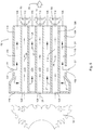
Fig. 5 is a section view of a heat exchanger according to at least one embodiment of the present disclosure; and -
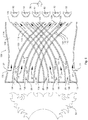
Fig. 6 is a section view of a heat exchanger according to at least one embodiment of the present disclosure. - Reference now will be made in detail to various embodiments, one or more examples of which are illustrated in the drawings. Each example is provided by way of explanation, not limitation. In fact, it will be apparent to those skilled in the art that various modifications and variations can be made in the present disclosure without departing from the scope or spirit of the embodiments. For instance, features illustrated or described as part of one embodiment can be used with another embodiment to yield a still further embodiment. Thus, it is intended that the present embodiments cover such modifications and variations as come within the scope of the appended claims and their equivalents.
- As used herein, the terms "first," "second," and "third" may be used interchangeably to distinguish one component from another and are not intended to signify location or importance of the individual components. The terms "upstream" and "downstream" refer to the relative direction with respect to fluid flow in a fluid pathway. For example, "upstream" refers to the direction from which the fluid flows, and "downstream" refers to the direction to which the fluid flows. The term "radially" refers to the relative direction that is substantially perpendicular to an axial centerline of a particular component, the term "axially" refers to the relative direction that is substantially to parallel and/or coaxially aligned with an axial centerline of a particular component, and the term "circumferentially" refers to the relative direction that extends around the axial centerline of a particular component.
- The terminology used herein is for the purpose of describing particular embodiments only and is not intended to be limiting. As used herein, the singular forms "a", "an" and "the" are intended to include the plural forms as well, unless the context clearly indicates otherwise. It will be further understood that the terms "comprises" and/or "comprising," when used in this specification, specify the presence of stated features, integers, steps, operations, elements, and/or components, but do not preclude the presence or addition of one or more other features, integers, steps, operations, elements, components, and/or groups thereof.
- Although exemplary embodiments of the present disclosure will be described generally in the context of a land based power generating gas turbine combustor for purposes of illustration, one of ordinary skill in the art will readily appreciate that embodiments of the present disclosure may be applied to any style or type of combustor for a turbomachine and are not limited to combustors or combustion systems for land based power generating gas turbines unless specifically recited in the claims.
- Referring now to the drawings,
Fig. 1 illustrates a schematic diagram of anexemplary gas turbine 10. Thegas turbine 10 generally includes aninlet section 12, acompressor 14 disposed downstream of theinlet section 12, at least onecombustor 16 disposed downstream of thecompressor 14, aturbine 18 disposed downstream of thecombustor 16 and anexhaust section 20 disposed downstream of theturbine 18. Additionally, thegas turbine 10 may include one ormore shafts 22 that couple thecompressor 14 to theturbine 18. - During operation,
air 24 flows through theinlet section 12 and into thecompressor 14 where theair 24 is progressively compressed, thus providingcompressed air 26 to thecombustor 16. At least a portion of thecompressed air 26 is mixed with afuel 28 within thecombustor 16 and burned to producecombustion gases 30. Thecombustion gases 30 flow from thecombustor 16 into theturbine 18, wherein energy (kinetic and/or thermal) is transferred from thecombustion gases 30 to rotor blades (not shown), thus causingshaft 22 to rotate. The mechanical rotational energy may then be used for various purposes such as to power thecompressor 14 and/or to generate electricity. Thecombustion gases 30 exiting theturbine 18 may then be exhausted from thegas turbine 10 via theexhaust section 20. - As shown in
Fig. 2 , thecombustor 16 may be at least partially surrounded by anouter casing 32 such as a compressor discharge casing. Theouter casing 32 may at least partially define ahigh pressure plenum 34 that at least partially surrounds various components of thecombustor 16. Thehigh pressure plenum 34 may be in fluid communication with the compressor 14 (Fig. 1 ) so as to receive thecompressed air 26 therefrom. Thecombustor 16 may be in fluid communication with thecompressor 14 such thatcompressed air 26 flows from thecompressor 14 to thecombustor 16, e.g., via thehigh pressure plenum 34. Anend cover 36 may be coupled to theouter casing 32. In particular embodiments, theouter casing 32 and theend cover 36 may at least partially define a head end volume orportion 38 of thecombustor 16. - In particular embodiments, the
head end portion 38 is in fluid communication with thehigh pressure plenum 34 and/or thecompressor 14. One or more liners orducts 40 may at least partially define acombustion chamber 42 for combusting the fuel-air mixture and/or may at least partially define ahot gas path 44 through the combustor, for directing thecombustion gases 30 towards an inlet to theturbine 18. As illustrated inFig. 2 , aheat exchanger 100 may be positioned in thecombustion chamber 42 so as to divide thecombustion chamber 42 into arich combustion zone 41 and a low-temperature zone 43. - In various embodiments, the
combustor 16 includes at least onefuel nozzle 48. As shown inFig. 2 , thefuel nozzle 48 may be coupled to theend cover 36 and extend towards thecombustion chamber 42. The one ormore fuel nozzles 48 may be in communication with afuel supply 46. Thecompressed air 26 received in thehead end 38 of thecombustor 16 may thus comprise a first portion of thecompressed air 26, also referred to as a combustion air portion, which flows to thefuel nozzle 48 for mixing with the fuel fromfuel supply 46. In some embodiments, thecombustor 16 may be configured to burn liquid fuel and thefuel supply 46 may provide liquid fuel to the combustor. Alternatively or in addition, any suitable fuel for combustion may be used, e.g., thecombustor 16 may be configured to burn gaseous fuel and thefuel supply 46 may provide gaseous fuel to thecombustor 16. A second portion of thecompressed air 26 may comprise a bypass air flow, and may be used as a coolingair flow 27 inheat exchanger 100, as described in more detail below. Various embodiments of thecombustor 16 may include different numbers and arrangements offuel nozzles 48 and is not limited to any particular number of fuel nozzles unless otherwise specified in the claims. For example, in particular configurations the one ormore fuel nozzles 48 may include multiple fuel nozzles annularly arranged about a center fuel nozzle. - According to the present disclosure, the temperature of combustion gases and hence the production of undesired emissions such as NOx may be reduced, while also providing more complete combustion at the reduced temperature. For example, some diffusion flames in turbomachine combustors have a stoichiometric temperature around 2450K, whereas the present disclosure may allow low NOx stable combustion via a diffusion flame with a lower stoichiometric temperature than a standard diffusion flame. In some embodiments, a diffusion flame may be produced having a temperature of about 2100K up to about 2300K corresponding to a global final temperature (the temperature obtained burning fuel with all the available air) of approximately 1300K up to approximately 2000K. Rich combustion temperatures may be in the range of about 1800K for equivalence ratio values around two. Accordingly, references herein such as "relatively cool diffuse flame" and/or "the low temperature zone" include relatively cool temperatures with reference to a standard diffusion flame of about 2450K. Further, as used herein, terms of approximation, such as "about," "generally," or "approximately," refer to being within ten percent above or below a stated value. Further, as used herein, such terms in the context of an angle or direction include within ten degrees.
- As shown in
Fig. 3 , thecombustor 16 may be configured to burn a fuel, which in some embodiments may be a liquid fuel, such as a dry oil, from thefuel nozzle 48, producing arich stage flame 50. Notably, thecombustor 16 may be configured to burn liquid fuel without requiring a diluent to lower the temperature and NOx level. However, as noted above, any suitable fuel for combustion may be used. In some embodiments, thecombustor 16 may be a single-stage combustor, e.g., thefuel nozzle 48 may be the only fuel supply to the combustor with no axial fuel staging. The combustion of the fuel may take place in a fuel-rich environment, such as in arich combustion zone 41. For example, the combustion air flow may include less than about one-third of thecompressed air 26, such as less than one-quarter of thecompressed air 26, such as less than one tenth of thecompressed air 26. The bypass flow which supplies the coolingair 27 to theheat exchanger 100 may comprise substantially the remainder of thecompressed air 26. In other embodiments, a third stage may be provided, e.g., thecombustor 16 may includerich combustion zone 41, diffusion flame 52 (downstream of the heat exchanger 100) inlow temperature zone 43 and a sequential burner (not shown) downstream of thelow temperature zone 43. In such embodiments,fuel 28 from thefuel supply 46 may be split between therich combustion zone 41 and the sequential burner. Axial fuel staging systems such as may include a sequential burner are generally understood in the art and the sequential burner is not described in further detail herein. - The
heat exchanger 100 may be positioned downstream of therich combustion zone 41 such thatcombustion gases 29 from therich combustion zone 41 may flow through theheat exchanger 100. Therich combustion gases 29 may be in thermal communication with coolingair 27, e.g., a bypass portion of thecompressed air 26, within theheat exchanger 100. Thus, alow temperature zone 43 may be provided downstream of theheat exchanger 100. As illustrated, a relatively cool diffuseflame 52 may thereby be formed in thelow temperature zone 43. Notably, in some embodiments, theheat exchanger 100 may not include any catalyst. Accordingly, some embodiments of the present disclosure may not include catalytic combustion. - As noted in
FIG. 3 thecombustor 16 may define an axial direction A, a radial direction R perpendicular to the axial direction A, and a circumferential direction C which extends around the axial direction A. As shown inFig. 3 , theheat exchanger 100 includes a plurality ofair passage 104 and a plurality ofcombustion gas passages 110. The plurality ofcombustion gas passages 110 are in thermal communication with the plurality ofair passages 104. Accordingly, thermal energy may be transferred from therich combustion gases 29 to the coolingair 27, cooling therich combustion gases 29 such that diffuseflame 52 may be provided. - The
air passages 104 and thecombustion gas passages 110 are preferably arranged in an alternating fashion. For example, in various embodiments, theheat exchanger 100 may be cylindrical. Accordingly, theair passages 104 and thecombustion gas passages 110 may be arranged along the circumferential direction, e.g., forming a ring of passages. As illustrated for example inFig. 4 , theheat exchanger 100 may include multiple rings of alternatingair passages 104 andcombustion gas passages 110.Fig. 4 illustrates anend plate 116 which may be provided at an aft end of ahousing 114 of theheat exchanger 100. Theend plate 116 illustrated inFig. 4 comprises a plurality of axially orientedcombustion gas inlets 108. Between each of the axially orientedcombustion gas inlets 108 theend cover 116 is blank, to effectively close off the air passages 104 (Fig. 5 ) from therich combustion gas 29. In the example embodiment illustrated byFig. 4 , theheat exchanger 100 includes four rings ofpassages passages heat exchanger 100 is not necessarily cylindrical, in some embodiments, the heat exchanger may take any other shape as may be suitable, e.g., the heat exchanger may have an oval or rectangular cross-section. - As may be seen in
Figs. 5 and6 , in various embodiments, theheat exchanger 100 includes ahousing 114 with a plurality of radially orientedair inlets 102 formed in thehousing 114. The air inlets 102 are in fluid communication with the plurality ofair passages 104. The plurality of coolingair passages 104 extend between the plurality ofair inlets 102 and a plurality ofair outlets 106 in fluid communication with thelow temperature zone 43. Also illustrated inFigs. 5 and6 , each of thecombustion gas passages 110 extends between acombustion gas inlet 108 in fluid communication with therich combustion zone 41 and acombustion gas outlet 112 in fluid communication with thelow temperature zone 43. -
Fig. 5 illustrates a micro-mixer embodiment of theheat exchanger 100 wherein a plurality oftubes 126 extend through anair plenum 118 defined within thehousing 114. In such embodiments, thehot gas passages 110 are defined within thetubes 126 and the portions ofair plenum 118 surrounding thetubes 126 define theair passages 104. Accordingly, in at least some embodiments, the coolingair passages 104 are not necessarily distinct passages, rather, the plurality of cooling air passages may be mutually contiguous. As illustrated inFig. 5 , thetubes 126 are generally straight, such that eachcombustion gas passage 110 of the plurality ofcombustion gas passages 110 extends along a generally straight line. As noted above, terms such as "generally," in the context of an angle or direction include within ten degrees, e.g., a generally straight line may include up to ten degrees of curvature. For example, the generallystraight tubes 126 may subtend an angle up to ten degrees. - As illustrated for example in
Fig. 6 , eachair passage 104 and eachcombustion gas passage 110 may extend along a curved line. In the illustrated example ofFig. 6 , theheat exchanger 100 comprises a plurality ofswirler vanes 120 formed therein. Eachpassage adjacent swirler vanes 120. Due to the alternating arrangement of thepassages swirler vane 120 partially defines acombustion gas passage 100 on afirst side 122 and partially defines a coolingair passage 104 on asecond side 124. For example, eachswirler vane 120 includes afirst side 122 andsecond side 124 opposing thefirst side 122. Further, thefirst side 122 of oneswirler vane 120 faces thefirst side 122 of anadjacent swirler vane 120, such that thecombustion gas passages 110 are defined between theadjacent swirler vanes 120 on afirst side 122 of theswirler vanes 120. Correspondingly, thesecond side 124 of eachswirler vane 120 faces thesecond side 124 of anotheradjacent swirler vane 120 and theair passages 104 are defined between the facingsecond sides 124 of theadjacent swirler vanes 120. Theswirler vanes 120 impart angular or circumferential swirl about the axial centerline of theheat exchanger 100 to the flows of therich combustions gases 29 and the coolingair 27 as they progress through theheat exchanger 100. - In some embodiments, a method of operating a
combustor 16 is provided. For example, the method may include supplying a fuel to the combustor 16 from afuel supply 46 and flowingcompressed air 26 to thecombustor 16. The method may further include mixing a first portion of thecompressed air 26 with the fuel from thefuel supply 46 and combusting the mixed fuel and air in arich combustion zone 41 to createrich combustion gases 29. The method may also include flowing therich combustion gases 29 through aheat exchanger 100 downstream of therich combustion zone 41 and flowing a second portion of thecompressed air 26 through theheat exchanger 100 such that therich combustion gases 29 and the second portion of the compressed air are in thermal communication within theheat exchanger 100. In some embodiments, thecombustor 16 may be a single-stage combustor 16 and thefuel supply 46 may be the only fuel source. - In some embodiments, flowing the second portion of the
compressed air 26 through theheat exchanger 100 may include flowing the second portion of thecompressed air 26 into anair plenum 118 within theheat exchanger 100. In additional embodiments, flowing therich combustion gases 29 through theheat exchanger 100 may include flowing therich combustion gases 29 between a plurality ofswirler vanes 120 on a first side of theswirler vanes 120, and flowing the second portion of the compressed air through theheat exchanger 100 may include flowing the second portion of the compressed air between the plurality ofswirler vanes 120 on a second side of theswirler vanes 120, the second side opposing the first side.
Claims (14)
- A combustor (16) for a turbomachine, the combustor (16) comprising:a rich combustion zone (41);a low temperature zone (43) downstream of the rich combustion zone (41); anda heat exchanger (100) positioned downstream of the rich combustion zone (41) and upstream of the low temperature zone (43), the heat exchanger (100) comprising:a plurality of air passages (104);a plurality of air inlets (102) in fluid communication with the plurality of air passages (104); anda plurality of combustion gas passages (110), each of the combustion gas passages (110) extending between a combustion gas inlet (108) in fluid communication with the rich combustion zone (41) and a combustion gas outlet (112) in fluid communication with the low temperature zone (43), the plurality of combustion gas passages (110) in thermal communication with the plurality of air passages (104).
- The combustor (16) of claim 1, wherein the combustor (16) is in fluid communication with a compressor (14) such that compressed air flows from the compressor (14) to the combustor (16), the combustor (16) further comprising a fuel nozzle (48), a first portion of the compressed air comprises a combustion air flow to the fuel nozzle (48) and a second portion of the compressed air comprises a bypass flow to the plurality of air inlets (102) of the heat exchanger (100).
- The combustor (16) of claim 1, wherein the heat exchanger (100) comprises an external housing and a cooling air plenum defined within the housing, the cooling air inlets (102) formed in the external housing and in fluid communication with the cooling air plenum.
- The combustor (16) of claim 3, wherein the plurality of cooling air passages (104) are formed in the cooling air plenum.
- The combustor (16) of claim 1, wherein the plurality of cooling air passages (104) are mutually contiguous.
- The combustor (16) of claim 1, wherein the plurality of cooling air passages (104) extend between the plurality of air inlets (102) and a plurality of air outlets in fluid communication with the low temperature zone (43).
- The combustor (16) of claim 1, wherein each combustion gas passage of the plurality of combustion gas passages (110) extends along a generally straight line.
- The combustor (16) of claim 1, wherein each combustion gas passage of the plurality of combustion gas passages (110) extends along a curved line.
- The combustor (16) of claim 1, wherein the combustor (16) is a single-stage combustor (16).
- A gas turbine (10), the gas turbine (10) comprising:a compressor (14);a turbine downstream from the compressor (14); anda combustor (16) of claim 1 disposed downstream from the compressor (14) and upstream from the turbine.
- A method of operating a combustor (16) of a turbomachine, wherein the combustor (16) is a single-stage combustor (16), the method comprising:supplying a fuel to the combustor (16) from a fuel supply;flowing compressed air to the combustor (16);mixing a first portion of the compressed air with the fuel from the fuel supply;combusting the mixed fuel and air in a rich combustion zone (41) to create combustion gases;flowing the combustion gases through a heat exchanger (100) downstream of the rich combustion zone (41); andflowing a second portion of the compressed air through the heat exchanger (100) such that the combustion gases and the second portion of the compressed air are in thermal communication within the heat exchanger (100).
- The method of claim 11, wherein supplying the fuel comprises supplying a liquid fuel.
- The method of claim 11, wherein flowing the second portion of the compressed air through the heat exchanger (100) comprises flowing the second portion of the compressed air into an air plenum within the heat exchanger (100).
- The method of claim 11, wherein flowing the combustion gases through the heat exchanger (100) comprises flowing the combustion gases between a plurality of swirler vanes (120) on a first side of the swirler vanes (120), and flowing the second portion of the compressed air through the heat exchanger (100) comprises flowing the second portion of the compressed air between the plurality of swirler vanes (120) on a second side of the swirler vanes (120), the second side opposing the first side.
Priority Applications (2)
| Application Number | Priority Date | Filing Date | Title |
|---|---|---|---|
| EP17177065.4A EP3418638B1 (en) | 2017-06-21 | 2017-06-21 | Combustor with heat exchanger |
| US15/978,635 US11041623B2 (en) | 2017-06-21 | 2018-05-14 | Gas turbine combustor with heat exchanger between rich combustion zone and secondary combustion zone |
Applications Claiming Priority (1)
| Application Number | Priority Date | Filing Date | Title |
|---|---|---|---|
| EP17177065.4A EP3418638B1 (en) | 2017-06-21 | 2017-06-21 | Combustor with heat exchanger |
Publications (2)
| Publication Number | Publication Date |
|---|---|
| EP3418638A1 true EP3418638A1 (en) | 2018-12-26 |
| EP3418638B1 EP3418638B1 (en) | 2021-03-24 |
Family
ID=59215516
Family Applications (1)
| Application Number | Title | Priority Date | Filing Date |
|---|---|---|---|
| EP17177065.4A Active EP3418638B1 (en) | 2017-06-21 | 2017-06-21 | Combustor with heat exchanger |
Country Status (2)
| Country | Link |
|---|---|
| US (1) | US11041623B2 (en) |
| EP (1) | EP3418638B1 (en) |
Cited By (1)
| Publication number | Priority date | Publication date | Assignee | Title |
|---|---|---|---|---|
| EP4685401A1 (en) * | 2024-07-22 | 2026-01-28 | General Electric Company | Gas turbine engine and fuel nozzle assembly therefor |
Families Citing this family (5)
| Publication number | Priority date | Publication date | Assignee | Title |
|---|---|---|---|---|
| CN111928295B (en) * | 2020-09-08 | 2024-05-14 | 中国科学院工程热物理研究所 | Micro-premixing on-duty nozzle assembly and gas turbine micro-premixing combustion chamber |
| KR102415892B1 (en) | 2021-01-27 | 2022-06-30 | 두산에너빌리티 주식회사 | Micromixer and combustor having the same |
| KR102460001B1 (en) | 2021-02-17 | 2022-10-26 | 두산에너빌리티 주식회사 | Micromixer module and combustor having the same |
| US12379107B2 (en) | 2023-12-01 | 2025-08-05 | Doosan Enerbility Co., Ltd. | Combustor nozzle, combustor and gas turbine including same |
| US12339007B2 (en) | 2023-12-01 | 2025-06-24 | Doosan Enerbility Co., Ltd. | Combustor nozzle, combustor and gas turbine including same |
Citations (5)
| Publication number | Priority date | Publication date | Assignee | Title |
|---|---|---|---|---|
| US3433015A (en) * | 1965-06-23 | 1969-03-18 | Nasa | Gas turbine combustion apparatus |
| US4240784A (en) * | 1978-09-25 | 1980-12-23 | Dauvergne Hector A | Three-stage liquid fuel burner |
| EP1620679A2 (en) * | 2003-04-30 | 2006-02-01 | Siemens Power Generation, Inc. | Non-catalytic combustor for reducing nox emissions |
| EP3037726A1 (en) * | 2014-12-22 | 2016-06-29 | Alstom Technology Ltd | Separate feedings of cooling and dilution air |
| EP3228937A1 (en) * | 2016-04-08 | 2017-10-11 | Ansaldo Energia Switzerland AG | Method for combusting a fuel, and combustion device |
Family Cites Families (2)
| Publication number | Priority date | Publication date | Assignee | Title |
|---|---|---|---|---|
| US3969892A (en) * | 1971-11-26 | 1976-07-20 | General Motors Corporation | Combustion system |
| US5239818A (en) * | 1992-03-30 | 1993-08-31 | General Electric Company | Dilution pole combustor and method |
-
2017
- 2017-06-21 EP EP17177065.4A patent/EP3418638B1/en active Active
-
2018
- 2018-05-14 US US15/978,635 patent/US11041623B2/en active Active
Patent Citations (5)
| Publication number | Priority date | Publication date | Assignee | Title |
|---|---|---|---|---|
| US3433015A (en) * | 1965-06-23 | 1969-03-18 | Nasa | Gas turbine combustion apparatus |
| US4240784A (en) * | 1978-09-25 | 1980-12-23 | Dauvergne Hector A | Three-stage liquid fuel burner |
| EP1620679A2 (en) * | 2003-04-30 | 2006-02-01 | Siemens Power Generation, Inc. | Non-catalytic combustor for reducing nox emissions |
| EP3037726A1 (en) * | 2014-12-22 | 2016-06-29 | Alstom Technology Ltd | Separate feedings of cooling and dilution air |
| EP3228937A1 (en) * | 2016-04-08 | 2017-10-11 | Ansaldo Energia Switzerland AG | Method for combusting a fuel, and combustion device |
Cited By (1)
| Publication number | Priority date | Publication date | Assignee | Title |
|---|---|---|---|---|
| EP4685401A1 (en) * | 2024-07-22 | 2026-01-28 | General Electric Company | Gas turbine engine and fuel nozzle assembly therefor |
Also Published As
| Publication number | Publication date |
|---|---|
| EP3418638B1 (en) | 2021-03-24 |
| US11041623B2 (en) | 2021-06-22 |
| US20180372318A1 (en) | 2018-12-27 |
Similar Documents
| Publication | Publication Date | Title |
|---|---|---|
| CN111578311B (en) | Fuel nozzle assembly | |
| US11041623B2 (en) | Gas turbine combustor with heat exchanger between rich combustion zone and secondary combustion zone | |
| EP4174379B1 (en) | Methods of operating a turbomachine combustor on hydrogen | |
| CN103017199B (en) | Burner and the method being used for supplying fuel to burner | |
| EP2619507B1 (en) | Combustor with a single limited fuel-air mixing burner and recuperated micro gas turbine | |
| US8015814B2 (en) | Turbine engine having folded annular jet combustor | |
| EP2551598B1 (en) | Method of operating a turbomachine | |
| US10222067B2 (en) | Combustor for a sequential gas turbine having a deflection unit between first and second combustion chambers | |
| JP2005098678A (en) | Method and apparatus for reducing gas turbine engine emissions | |
| US9803867B2 (en) | Premix pilot nozzle | |
| JP2014132214A (en) | Fuel injector for supplying fuel to combustor | |
| US20140352312A1 (en) | Injector for introducing a fuel-air mixture into a combustion chamber | |
| JP6110854B2 (en) | Tangential annular combustor with premixed fuel air for use in gas turbine engines | |
| CN102809176A (en) | Aerodynamic fuel nozzle | |
| EP3102877A1 (en) | Combustor | |
| JP2014526030A (en) | Annular cylindrical combustor with premixed tangential fuel air nozzle for use in a gas turbine engine | |
| JP6595010B2 (en) | Fuel nozzle assembly having a premix flame stabilizer | |
| CN113864818A (en) | Combustor air flow path | |
| EP3425281A1 (en) | Pilot nozzle with inline premixing | |
| US11885498B2 (en) | Turbine engine with fuel system including a catalytic reformer | |
| US20170074520A1 (en) | Combustor | |
| CN107191967A (en) | Combustion Liner Cooling | |
| CN116293796B (en) | Burner with igniter | |
| JP2014524561A (en) | Annular and flameless annular combustor for use in gas turbine engines | |
| CN107191966B (en) | Combustion liner cooling |
Legal Events
| Date | Code | Title | Description |
|---|---|---|---|
| PUAI | Public reference made under article 153(3) epc to a published international application that has entered the european phase |
Free format text: ORIGINAL CODE: 0009012 |
|
| STAA | Information on the status of an ep patent application or granted ep patent |
Free format text: STATUS: THE APPLICATION HAS BEEN PUBLISHED |
|
| AK | Designated contracting states |
Kind code of ref document: A1 Designated state(s): AL AT BE BG CH CY CZ DE DK EE ES FI FR GB GR HR HU IE IS IT LI LT LU LV MC MK MT NL NO PL PT RO RS SE SI SK SM TR |
|
| AX | Request for extension of the european patent |
Extension state: BA ME |
|
| STAA | Information on the status of an ep patent application or granted ep patent |
Free format text: STATUS: REQUEST FOR EXAMINATION WAS MADE |
|
| 17P | Request for examination filed |
Effective date: 20190625 |
|
| RBV | Designated contracting states (corrected) |
Designated state(s): AL AT BE BG CH CY CZ DE DK EE ES FI FR GB GR HR HU IE IS IT LI LT LU LV MC MK MT NL NO PL PT RO RS SE SI SK SM TR |
|
| STAA | Information on the status of an ep patent application or granted ep patent |
Free format text: STATUS: EXAMINATION IS IN PROGRESS |
|
| GRAP | Despatch of communication of intention to grant a patent |
Free format text: ORIGINAL CODE: EPIDOSNIGR1 |
|
| STAA | Information on the status of an ep patent application or granted ep patent |
Free format text: STATUS: GRANT OF PATENT IS INTENDED |
|
| 17Q | First examination report despatched |
Effective date: 20200428 |
|
| INTG | Intention to grant announced |
Effective date: 20200605 |
|
| GRAJ | Information related to disapproval of communication of intention to grant by the applicant or resumption of examination proceedings by the epo deleted |
Free format text: ORIGINAL CODE: EPIDOSDIGR1 |
|
| GRAL | Information related to payment of fee for publishing/printing deleted |
Free format text: ORIGINAL CODE: EPIDOSDIGR3 |
|
| GRAS | Grant fee paid |
Free format text: ORIGINAL CODE: EPIDOSNIGR3 |
|
| STAA | Information on the status of an ep patent application or granted ep patent |
Free format text: STATUS: EXAMINATION IS IN PROGRESS |
|
| INTC | Intention to grant announced (deleted) | ||
| GRAR | Information related to intention to grant a patent recorded |
Free format text: ORIGINAL CODE: EPIDOSNIGR71 |
|
| STAA | Information on the status of an ep patent application or granted ep patent |
Free format text: STATUS: GRANT OF PATENT IS INTENDED |
|
| GRAA | (expected) grant |
Free format text: ORIGINAL CODE: 0009210 |
|
| STAA | Information on the status of an ep patent application or granted ep patent |
Free format text: STATUS: THE PATENT HAS BEEN GRANTED |
|
| INTG | Intention to grant announced |
Effective date: 20210211 |
|
| AK | Designated contracting states |
Kind code of ref document: B1 Designated state(s): AL AT BE BG CH CY CZ DE DK EE ES FI FR GB GR HR HU IE IS IT LI LT LU LV MC MK MT NL NO PL PT RO RS SE SI SK SM TR |
|
| REG | Reference to a national code |
Ref country code: GB Ref legal event code: FG4D |
|
| REG | Reference to a national code |
Ref country code: CH Ref legal event code: EP |
|
| REG | Reference to a national code |
Ref country code: IE Ref legal event code: FG4D |
|
| REG | Reference to a national code |
Ref country code: AT Ref legal event code: REF Ref document number: 1374850 Country of ref document: AT Kind code of ref document: T Effective date: 20210415 Ref country code: DE Ref legal event code: R096 Ref document number: 602017035087 Country of ref document: DE |
|
| REG | Reference to a national code |
Ref country code: LT Ref legal event code: MG9D |
|
| PG25 | Lapsed in a contracting state [announced via postgrant information from national office to epo] |
Ref country code: BG Free format text: LAPSE BECAUSE OF FAILURE TO SUBMIT A TRANSLATION OF THE DESCRIPTION OR TO PAY THE FEE WITHIN THE PRESCRIBED TIME-LIMIT Effective date: 20210624 Ref country code: FI Free format text: LAPSE BECAUSE OF FAILURE TO SUBMIT A TRANSLATION OF THE DESCRIPTION OR TO PAY THE FEE WITHIN THE PRESCRIBED TIME-LIMIT Effective date: 20210324 Ref country code: GR Free format text: LAPSE BECAUSE OF FAILURE TO SUBMIT A TRANSLATION OF THE DESCRIPTION OR TO PAY THE FEE WITHIN THE PRESCRIBED TIME-LIMIT Effective date: 20210625 Ref country code: HR Free format text: LAPSE BECAUSE OF FAILURE TO SUBMIT A TRANSLATION OF THE DESCRIPTION OR TO PAY THE FEE WITHIN THE PRESCRIBED TIME-LIMIT Effective date: 20210324 Ref country code: NO Free format text: LAPSE BECAUSE OF FAILURE TO SUBMIT A TRANSLATION OF THE DESCRIPTION OR TO PAY THE FEE WITHIN THE PRESCRIBED TIME-LIMIT Effective date: 20210624 |
|
| PG25 | Lapsed in a contracting state [announced via postgrant information from national office to epo] |
Ref country code: SE Free format text: LAPSE BECAUSE OF FAILURE TO SUBMIT A TRANSLATION OF THE DESCRIPTION OR TO PAY THE FEE WITHIN THE PRESCRIBED TIME-LIMIT Effective date: 20210324 Ref country code: RS Free format text: LAPSE BECAUSE OF FAILURE TO SUBMIT A TRANSLATION OF THE DESCRIPTION OR TO PAY THE FEE WITHIN THE PRESCRIBED TIME-LIMIT Effective date: 20210324 Ref country code: LV Free format text: LAPSE BECAUSE OF FAILURE TO SUBMIT A TRANSLATION OF THE DESCRIPTION OR TO PAY THE FEE WITHIN THE PRESCRIBED TIME-LIMIT Effective date: 20210324 |
|
| REG | Reference to a national code |
Ref country code: NL Ref legal event code: MP Effective date: 20210324 |
|
| REG | Reference to a national code |
Ref country code: AT Ref legal event code: MK05 Ref document number: 1374850 Country of ref document: AT Kind code of ref document: T Effective date: 20210324 |
|
| PG25 | Lapsed in a contracting state [announced via postgrant information from national office to epo] |
Ref country code: NL Free format text: LAPSE BECAUSE OF FAILURE TO SUBMIT A TRANSLATION OF THE DESCRIPTION OR TO PAY THE FEE WITHIN THE PRESCRIBED TIME-LIMIT Effective date: 20210324 |
|
| PG25 | Lapsed in a contracting state [announced via postgrant information from national office to epo] |
Ref country code: EE Free format text: LAPSE BECAUSE OF FAILURE TO SUBMIT A TRANSLATION OF THE DESCRIPTION OR TO PAY THE FEE WITHIN THE PRESCRIBED TIME-LIMIT Effective date: 20210324 Ref country code: CZ Free format text: LAPSE BECAUSE OF FAILURE TO SUBMIT A TRANSLATION OF THE DESCRIPTION OR TO PAY THE FEE WITHIN THE PRESCRIBED TIME-LIMIT Effective date: 20210324 Ref country code: LT Free format text: LAPSE BECAUSE OF FAILURE TO SUBMIT A TRANSLATION OF THE DESCRIPTION OR TO PAY THE FEE WITHIN THE PRESCRIBED TIME-LIMIT Effective date: 20210324 Ref country code: SM Free format text: LAPSE BECAUSE OF FAILURE TO SUBMIT A TRANSLATION OF THE DESCRIPTION OR TO PAY THE FEE WITHIN THE PRESCRIBED TIME-LIMIT Effective date: 20210324 Ref country code: AT Free format text: LAPSE BECAUSE OF FAILURE TO SUBMIT A TRANSLATION OF THE DESCRIPTION OR TO PAY THE FEE WITHIN THE PRESCRIBED TIME-LIMIT Effective date: 20210324 |
|
| PG25 | Lapsed in a contracting state [announced via postgrant information from national office to epo] |
Ref country code: IS Free format text: LAPSE BECAUSE OF FAILURE TO SUBMIT A TRANSLATION OF THE DESCRIPTION OR TO PAY THE FEE WITHIN THE PRESCRIBED TIME-LIMIT Effective date: 20210724 Ref country code: PT Free format text: LAPSE BECAUSE OF FAILURE TO SUBMIT A TRANSLATION OF THE DESCRIPTION OR TO PAY THE FEE WITHIN THE PRESCRIBED TIME-LIMIT Effective date: 20210726 Ref country code: PL Free format text: LAPSE BECAUSE OF FAILURE TO SUBMIT A TRANSLATION OF THE DESCRIPTION OR TO PAY THE FEE WITHIN THE PRESCRIBED TIME-LIMIT Effective date: 20210324 Ref country code: RO Free format text: LAPSE BECAUSE OF FAILURE TO SUBMIT A TRANSLATION OF THE DESCRIPTION OR TO PAY THE FEE WITHIN THE PRESCRIBED TIME-LIMIT Effective date: 20210324 Ref country code: SK Free format text: LAPSE BECAUSE OF FAILURE TO SUBMIT A TRANSLATION OF THE DESCRIPTION OR TO PAY THE FEE WITHIN THE PRESCRIBED TIME-LIMIT Effective date: 20210324 |
|
| REG | Reference to a national code |
Ref country code: DE Ref legal event code: R097 Ref document number: 602017035087 Country of ref document: DE |
|
| PG25 | Lapsed in a contracting state [announced via postgrant information from national office to epo] |
Ref country code: ES Free format text: LAPSE BECAUSE OF FAILURE TO SUBMIT A TRANSLATION OF THE DESCRIPTION OR TO PAY THE FEE WITHIN THE PRESCRIBED TIME-LIMIT Effective date: 20210324 Ref country code: DK Free format text: LAPSE BECAUSE OF FAILURE TO SUBMIT A TRANSLATION OF THE DESCRIPTION OR TO PAY THE FEE WITHIN THE PRESCRIBED TIME-LIMIT Effective date: 20210324 Ref country code: AL Free format text: LAPSE BECAUSE OF FAILURE TO SUBMIT A TRANSLATION OF THE DESCRIPTION OR TO PAY THE FEE WITHIN THE PRESCRIBED TIME-LIMIT Effective date: 20210324 Ref country code: MC Free format text: LAPSE BECAUSE OF FAILURE TO SUBMIT A TRANSLATION OF THE DESCRIPTION OR TO PAY THE FEE WITHIN THE PRESCRIBED TIME-LIMIT Effective date: 20210324 |
|
| REG | Reference to a national code |
Ref country code: CH Ref legal event code: PL |
|
| PLBE | No opposition filed within time limit |
Free format text: ORIGINAL CODE: 0009261 |
|
| STAA | Information on the status of an ep patent application or granted ep patent |
Free format text: STATUS: NO OPPOSITION FILED WITHIN TIME LIMIT |
|
| GBPC | Gb: european patent ceased through non-payment of renewal fee |
Effective date: 20210624 |
|
| PG25 | Lapsed in a contracting state [announced via postgrant information from national office to epo] |
Ref country code: SI Free format text: LAPSE BECAUSE OF FAILURE TO SUBMIT A TRANSLATION OF THE DESCRIPTION OR TO PAY THE FEE WITHIN THE PRESCRIBED TIME-LIMIT Effective date: 20210324 |
|
| 26N | No opposition filed |
Effective date: 20220104 |
|
| REG | Reference to a national code |
Ref country code: BE Ref legal event code: MM Effective date: 20210630 |
|
| PG25 | Lapsed in a contracting state [announced via postgrant information from national office to epo] |
Ref country code: LU Free format text: LAPSE BECAUSE OF NON-PAYMENT OF DUE FEES Effective date: 20210621 |
|
| PG25 | Lapsed in a contracting state [announced via postgrant information from national office to epo] |
Ref country code: LI Free format text: LAPSE BECAUSE OF NON-PAYMENT OF DUE FEES Effective date: 20210630 Ref country code: IE Free format text: LAPSE BECAUSE OF NON-PAYMENT OF DUE FEES Effective date: 20210621 Ref country code: GB Free format text: LAPSE BECAUSE OF NON-PAYMENT OF DUE FEES Effective date: 20210624 Ref country code: CH Free format text: LAPSE BECAUSE OF NON-PAYMENT OF DUE FEES Effective date: 20210630 |
|
| PG25 | Lapsed in a contracting state [announced via postgrant information from national office to epo] |
Ref country code: IS Free format text: LAPSE BECAUSE OF FAILURE TO SUBMIT A TRANSLATION OF THE DESCRIPTION OR TO PAY THE FEE WITHIN THE PRESCRIBED TIME-LIMIT Effective date: 20210724 Ref country code: FR Free format text: LAPSE BECAUSE OF NON-PAYMENT OF DUE FEES Effective date: 20210630 |
|
| PG25 | Lapsed in a contracting state [announced via postgrant information from national office to epo] |
Ref country code: BE Free format text: LAPSE BECAUSE OF NON-PAYMENT OF DUE FEES Effective date: 20210630 |
|
| PG25 | Lapsed in a contracting state [announced via postgrant information from national office to epo] |
Ref country code: IT Free format text: LAPSE BECAUSE OF FAILURE TO SUBMIT A TRANSLATION OF THE DESCRIPTION OR TO PAY THE FEE WITHIN THE PRESCRIBED TIME-LIMIT Effective date: 20210324 |
|
| PG25 | Lapsed in a contracting state [announced via postgrant information from national office to epo] |
Ref country code: CY Free format text: LAPSE BECAUSE OF FAILURE TO SUBMIT A TRANSLATION OF THE DESCRIPTION OR TO PAY THE FEE WITHIN THE PRESCRIBED TIME-LIMIT Effective date: 20210324 |
|
| PG25 | Lapsed in a contracting state [announced via postgrant information from national office to epo] |
Ref country code: HU Free format text: LAPSE BECAUSE OF FAILURE TO SUBMIT A TRANSLATION OF THE DESCRIPTION OR TO PAY THE FEE WITHIN THE PRESCRIBED TIME-LIMIT; INVALID AB INITIO Effective date: 20170621 |
|
| REG | Reference to a national code |
Ref country code: DE Ref legal event code: R081 Ref document number: 602017035087 Country of ref document: DE Owner name: GENERAL ELECTRIC TECHNOLOGY GMBH, CH Free format text: FORMER OWNER: GENERAL ELECTRIC COMPANY, SCHENECTADY, NY, US |
|
| PG25 | Lapsed in a contracting state [announced via postgrant information from national office to epo] |
Ref country code: MK Free format text: LAPSE BECAUSE OF FAILURE TO SUBMIT A TRANSLATION OF THE DESCRIPTION OR TO PAY THE FEE WITHIN THE PRESCRIBED TIME-LIMIT Effective date: 20210324 |
|
| PG25 | Lapsed in a contracting state [announced via postgrant information from national office to epo] |
Ref country code: MT Free format text: LAPSE BECAUSE OF FAILURE TO SUBMIT A TRANSLATION OF THE DESCRIPTION OR TO PAY THE FEE WITHIN THE PRESCRIBED TIME-LIMIT Effective date: 20210324 |
|
| PGFP | Annual fee paid to national office [announced via postgrant information from national office to epo] |
Ref country code: DE Payment date: 20250520 Year of fee payment: 9 |
|
| PG25 | Lapsed in a contracting state [announced via postgrant information from national office to epo] |
Ref country code: TR Free format text: LAPSE BECAUSE OF FAILURE TO SUBMIT A TRANSLATION OF THE DESCRIPTION OR TO PAY THE FEE WITHIN THE PRESCRIBED TIME-LIMIT Effective date: 20210324 |