EP3418611A1 - Check valves - Google Patents
Check valves Download PDFInfo
- Publication number
- EP3418611A1 EP3418611A1 EP17461551.8A EP17461551A EP3418611A1 EP 3418611 A1 EP3418611 A1 EP 3418611A1 EP 17461551 A EP17461551 A EP 17461551A EP 3418611 A1 EP3418611 A1 EP 3418611A1
- Authority
- EP
- European Patent Office
- Prior art keywords
- flapper
- valve
- flapper element
- check valve
- spring damping
- Prior art date
- Legal status (The legal status is an assumption and is not a legal conclusion. Google has not performed a legal analysis and makes no representation as to the accuracy of the status listed.)
- Granted
Links
Images



Classifications
-
- F—MECHANICAL ENGINEERING; LIGHTING; HEATING; WEAPONS; BLASTING
- F16—ENGINEERING ELEMENTS AND UNITS; GENERAL MEASURES FOR PRODUCING AND MAINTAINING EFFECTIVE FUNCTIONING OF MACHINES OR INSTALLATIONS; THERMAL INSULATION IN GENERAL
- F16K—VALVES; TAPS; COCKS; ACTUATING-FLOATS; DEVICES FOR VENTING OR AERATING
- F16K15/00—Check valves
- F16K15/02—Check valves with guided rigid valve members
- F16K15/03—Check valves with guided rigid valve members with a hinged closure member or with a pivoted closure member
-
- F—MECHANICAL ENGINEERING; LIGHTING; HEATING; WEAPONS; BLASTING
- F16—ENGINEERING ELEMENTS AND UNITS; GENERAL MEASURES FOR PRODUCING AND MAINTAINING EFFECTIVE FUNCTIONING OF MACHINES OR INSTALLATIONS; THERMAL INSULATION IN GENERAL
- F16K—VALVES; TAPS; COCKS; ACTUATING-FLOATS; DEVICES FOR VENTING OR AERATING
- F16K15/00—Check valves
- F16K15/02—Check valves with guided rigid valve members
- F16K15/021—Check valves with guided rigid valve members the valve member being a movable body around which the medium flows when the valve is open
- F16K15/023—Check valves with guided rigid valve members the valve member being a movable body around which the medium flows when the valve is open the valve member consisting only of a predominantly disc-shaped flat element
-
- F—MECHANICAL ENGINEERING; LIGHTING; HEATING; WEAPONS; BLASTING
- F16—ENGINEERING ELEMENTS AND UNITS; GENERAL MEASURES FOR PRODUCING AND MAINTAINING EFFECTIVE FUNCTIONING OF MACHINES OR INSTALLATIONS; THERMAL INSULATION IN GENERAL
- F16K—VALVES; TAPS; COCKS; ACTUATING-FLOATS; DEVICES FOR VENTING OR AERATING
- F16K47/00—Means in valves for absorbing fluid energy
- F16K47/02—Means in valves for absorbing fluid energy for preventing water-hammer or noise
- F16K47/023—Means in valves for absorbing fluid energy for preventing water-hammer or noise for preventing water-hammer, e.g. damping of the valve movement
Definitions
- the present disclosure relates to check valves.
- check valves It is known to use check valves to allow fluid flow in one direction therethrough, and to prevent flow in the opposite direction.
- Check valves are widely used in a wide variety of applications, for example in air conditioning systems, for example in aircraft air conditioning systems.
- check valve includes a pair of hinged flappers that pivot open in the direction of fluid flow when the fluid pressure differential exceeds a predetermined valve "cracking pressure". If a negative pressure differential exists across the valve, the flapper elements close, preventing flow reversal.
- check valve includes just a single flapper element which opens and closes depending on the pressure differential across the valve.
- the present disclosure relates to a check valve of the latter type.
- the present disclosure provides a check valve.
- the check valve comprises a valve housing defining a valve opening and a flapper element having a proximal end.
- the flapper element is pivotally mounted to the valve housing adjacent the periphery of the valve opening at its proximal end for pivotal movement between a closed position, in which it blocks the flow of fluid through the valve opening and a fully open position in which it permits the flow of fluid through the valve opening.
- the check valve further comprises at least one spring damping element located between the flapper element and the valve housing for providing a damping force resisting the pivotal movement of the flapper element towards its open position
- the at least one spring damping element is operable to produce a damping force only over a final range of the pivotal movement of the flapper element as it approaches its fully open position.
- the spring damping element may be is operable to produce a damping force only in the final 45° of pivotal movement of the flapper element towards its fully open position, for example only in the final 30° or final 20° of pivotal movement of the flapper element towards its fully open position.
- the check valve may comprise a plurality of spring damping elements which are operable successively to increase the damping force as the flapper element approaches its fully open position.
- the proximal end of the flapper element and the valve housing may comprise surfaces arranged opposed to one another in the fully open position of the flapper element, the at least one spring damping element projecting from one or other of the opposed surfaces when the flapper element is in its closed position and engaging an associated opposed surface as the flapper element moves towards its open position.
- a flapper element surface may be arranged generally perpendicularly to the plane of the flapper element and an associated opposed valve housing surface may be arranged generally parallel to the plane of the valve opening.
- a first spring damping element may extending from one of those surfaces.
- a first spring damping element may extend from the valve housing surface.
- the check valve may comprising a pair of valve housing surfaces arranged on opposed sides of a centreline of the valve housing, with respective first spring damping elements extending from the respective valve housing surfaces.
- the valve housing surface may is formed as a shoulder in or adjacent a mounting post for the flapper element.
- the flapper element may comprise a proximal extension, with an opposed surface being provided on the extension and the valve housing may comprise an associated valve housing surface.
- One or more second spring damping elements may project from one or other of the surfaces.
- the second spring damping element projects from the valve housing surface.
- the check valve may comprise the first and second spring damping elements and wherein the second spring damping element may be is operable before the first spring damping element as the flapper element approaches its fully open position.
- One or more pairs of the opposed surfaces provided on the flapper element and the valve housing may be stop surfaces, coming into contact with one another when the flapper element is in its open position.
- the spring damping element may comprises a bumper element at a distal end thereof for engagement with the flapper element or valve housing.
- the bumper element may be is slidably mounted in a bore of the valve housing or flapper element.
- a distal end of the bumper element may be rounded.
- the flapper element may be curved in a plane perpendicular to its longitudinal centreline and the valve opening may be is provided with a raised lip having a profile complementary to the periphery of the flapper element for sealing engagement therewith.
- the valve opening may be generally circular in shape.
- the flapper element may comprise one or more reinforcing ribs formed therein.
- the reinforcing ribs may comprise a central longitudinal rib, with additional ribs extending therefrom.
- a check valve 2 comprises a valve housing 4 and a single flapper element 6 pivotally mounted to the valve housing 4 at a proximal end 8 of the flapper element 6 through a hinge pin 10.
- the valve housing 4 is generally annular in shape, defining a generally circular valve opening 12 surrounded by a generally annular flange 14.
- the annular flange 14 will be suitably supported in a pipe or duct through which a fluid, for example a gas such as air flows.
- the annular flange 14 may be integrally formed with a portion of the duct.
- the disclosure is not, limited to circularshaped housings 4 and other housing shapes may be used.
- the flapper element 6 is pivotally mounted for rotation between a closed position shown for example in Figure 8 and a fully opened position shown for example in Figures 1 and 5 . In the closed position, the flapper element 6 blocks the flow of fluid through the valve opening 12. In the fully open position, and in intermediate positions, the flapper element 6 allows fluid to flow through the valve opening 12.
- first spring damping elements 16, and a second spring damping element 18 are arranged between the flapper element 6 and the valve housing 4 to damp the impact of the flapper element 6 on the valve housing 4 as it moves to its fully open position.
- first and second spring damping elements 16, 18 are only operable to produce a damping force in a final range of pivotal movement of the flapper element 6 as it approaches its fully open position.
- the flapper element 6 comprises a flapper body 20 which, when viewed from above or below, is circular in shape for closing the valve opening 12.
- the particular shape of the flapper body 20 will be determined by the shape of the valve opening 12 and is not limited to a circular shape.
- the flapper element 6 is generally symmetrical about its longitudinal centreline A.
- the flapper element 6 comprises a proximal end 8 by which it is mounted to the valve housing 4.
- the proximal end 8 comprises a mounting portion 22 extending upwardly from the upper surface 24 of the flapper body 20 and a proximal extension 26 extending away from the mounting portion 22 axially relative to the flapper element's centreline A.
- respective surfaces 28 are formed on the rearward surface of the mounting portion 22 on either side of the proximal extension 26. These surfaces 28 will oppose corresponding surfaces 60 in the valve housing 4 when the flapper element 6 is in the fully open position.
- the surfaces 28 face rearwardly, i.e. away from the flapper body 20. In this particular embodiment they are arranged generally perpendicular to the plane of the flapper element 6.
- the mounting portion 22 further comprises a pair of hinge pins 30 projecting laterally therefrom in a direction generally perpendicular to the flapper element centreline A.
- the hinge pins 30 may be formed integrally with the flapper element 6 or formed as separate elements and suitably mounted to the mounting portion 22.
- the hinge pins 30 may be formed as end portions of an elongate pin projecting from both sides of the mounting portion 22.
- the hinge pins 30 may, for example, be insert moulded or insert cast into the flapper element 6 during manufacture of the flapper element 6.
- the mounting portion 22 may be provided with a bore extending therethrough which pivotally receives a hinge pin 30.
- the hinge pin 30 may be provided with a flange and bolted or otherwise fastened to the flapper element 6.
- the proximal extension 26 is provided with a bore 30 in its downwardly facing stop surface 32 for receiving the second spring damping element 18.
- the second spring damping element 18 comprises a spring element 34, for example a coil spring, and a bumper element 36 which is slidably received in the bore 30.
- the spring element 34 and bumper element 36 are retained in the bore 30 by means of a fastening ring 38 which may, for example, be threadedly mounted in the mouth of the bore 30.
- the bumper element 36 comprises a shoulder 40 which engages the fastening ring 38 when the bumper element 36 is biased fully outwardly of the bore 30 by the spring element 34, as shown in Figure 2 .
- the spring element 34 and bumper element 36 may be retained in the bore 30 by any suitable manner.
- the amount by which the bumper element 36 projects from the surface 32 may be determined by appropriate sizing and/or positioning of the fastening ring 38 for example. As will be described further below, and as can be seen from Figure 12 , when the flapper element 6 moves to its closed position, the bumper element 36 will move into contact with a stop surface 70 of a raised lip 48 of the valve housing 4. The distal end 37 of the bumper element 36 may be rounded, as illustrated, to facilitate engagement with the opposed surface 70 of the valve housing 4.
- the body 20 of the flapper element 6 is curved about its centreline A in a direction towards the valve opening 12.
- the flapper element 6 is arcuate, for example circularly arcuate, in a plane perpendicular to the centreline A.
- this curvature may provide certain advantages.
- the flapper body 20 is also provided with one or more strengthening ribs 42 which extend along the upper surface 24 of the flapper body 20 in a direction generally perpendicular to the centreline A of the flapper body 20.
- the ribs 42 extend from a central, axially extending rib 44 which extends generally parallel to the centreline A of the flapper body 20 from the mounting portion 22 of the flapper element 6.
- the dimensions, for example the axial length of the central rib 44 may be chosen to provide an appropriate mass and thus moment of inertia for the flapper element 6.
- the central rib 44 may, as illustrated, extend only over a proportion of the axial dimensional of the flapper element 6.
- the central rib 44 may be simply replaced by a suitable point mass.
- the shape, number and spatial arrangement of the strengthening ribs 42 may differ from that illustrated.
- valve housing 4 it can be seen, for example from Figure 9 , that the valve opening 12 is surrounded by a raised lip 48 having a sealing surface 50.
- the shape of the sealing surface 50 is complementary to the shape of the periphery of the flapper body 20 so as to provide a seal between the two when the flapper element 6 is in the closed position.
- the sealing surface 50 slopes downwardly and outwardly relative to the valve opening 12.
- the flapper element 6 is pivotally mounted to the valve housing 4 by one or more hinge pins 30.
- the valve housing 4 comprises a pair of mounting posts 52 extending upwardly from the annular flange 14 of the valve housing 4. As illustrated in Figure 9 , for example, the mounting posts 52 extend beyond the raised lip 48 surrounding the valve opening 12.
- Each mounting post 52 comprises a bore 54 which receives the hinge pin(s) 30 of the flapper element 6.
- the hinge pins 30 may be rotatably received within the mounting bores 54 or rotationally fixed with respect thereto, in which case, the flapper element 6 will pivot around the hinge pin 30.
- the mounting post 52 is formed contiguously with the raised lip 48. However, that is not essential and it may be formed spaced therefrom.
- the mounting post 52 is further provided with a laterally inwardly extending portion 56, in this embodiment a shoulder, which, for strength purposes, is connected to the lip 48 by a web of material 58.
- the portion 56 may be separate from the mounting post 52 and/or the raised lip 48.
- An upwardly facing surface 60 is formed on the upper end of each stop portion 56. In this embodiment, the surface 60 is generally parallel to the plane of the valve opening 12.
- Each portion 56 is also provided with a bore 62 extending from the surface 60.
- the bore 62 receives a first spring damping element 16.
- the spring damping element 16 is similar in construction to the second spring damping element 18 mounted in the flapper element 6, having a bumper element 64 which is spring biased out of the bore 62 by a spring element 66, for example a coil spring as shown.
- the bumper element 64 and spring element 66 may be retained in the bore 62 in a similar manner to the first spring damping element 14 for example, or in any suitable manner.
- the amount by which the bumper element 64 projects from the bore 62 may be set in a similar manner to that described above or some other suitable manner.
- a distal end 65 of the bumper element 36 may be rounded, as illustrated.
- the particular rotational angle at which contact is made between the bumper element 38 and the surface 28 can be chosen to provide the desired opening and damping characteristics. Typically, however, this contact may occur once the flapper element 6 has rotated to within 45°, for example within 30° or 20° of its fully closed position.
- the second damping element 18 thus begins to provide a damping force which begins to damp the movement of the flapper element 6. It will be appreciated that as there is no damping over the initial range of pivotal movement of the flapper element 6, the flapper element 6 is able to open quickly.
- the first spring damping elements 16 will contact the surfaces 28 of the flapper element 6. This increases the damping force on the flapper element 6 as it moves to its fully open position. Again the precise position at which the first spring damping elements 16 become effective can be determined by the amount they project from the stop surface 60 and can be chosen to provide the desired opening and damping characteristics.
- the spring damping elements 16, 18 therefore become effective sequentially, allowing the damping effect to be varied as the flapper element rotates.
- the springs 66 of the first spring damping elements 16 have a higher spring constant than the springs 32 of the second spring damping element 18 such that they contribute the largest amount of damping force.
- the second spring damping element 18 thus provides preliminary, relatively low damping.
- the relative spring constants may be chosen to give the desired damping profile.
- stop surfaces of the flapper element 6 and the valve housing 4 come into contact and the valve 2 is maintained open by means of the pressure differential across the valve 2.
- the downwardly facing surface 32 of the flapper element proximal extension 26 and the surface portion 70 of the lip 48 of the valve housing 4 form stop surfaces.
- the surfaces 28 of the flapper valve mounting portion 22 and surfaces 60 of the valve housing 4 may provide stop surfaces.
- the curved form of the flapper body 20 may be advantageous in this regard in that it will allow the flapper body 20 to flex, thereby damping the impact of the flapper body 20 with the sealing surface 50.
- the check valve 2 may be provided with just one set of spring damping elements 16, 18.
- the second spring damping element 18 may be omitted.
- the first spring damping elements 16 may be omitted or their number varied. It may be that the first spring damping elements 16 are particularly advantageous, as the valve housing 4 may provide a larger mass of material in which to mount the first spring damping elements 16.
- the curved shape of the flapper body 20 in this embodiment may also be advantageous, not only for the damping effect upon closure, but also as it will mitigate the possibility of the flapper element 6 interfering with the duct in which the check valve 2 is placed. Also, as illustrated in Figure 2 , the curved shape maximises the open flow area through the valve opening 12, thereby reducing pressure losses through the check valve 2.
- the described embodiment provides a check valve 2 in which impact forces between the flapper element 6 and the valve housing 4 are reduced due to the spring damping elements 16, 18. This may reduce impact damage, particularly on the flapper element 6, thereby leading to improved operational life of the check valve 2.
Landscapes
- Engineering & Computer Science (AREA)
- General Engineering & Computer Science (AREA)
- Mechanical Engineering (AREA)
- Check Valves (AREA)
Abstract

Description
- The present disclosure relates to check valves.
- It is known to use check valves to allow fluid flow in one direction therethrough, and to prevent flow in the opposite direction. Check valves are widely used in a wide variety of applications, for example in air conditioning systems, for example in aircraft air conditioning systems.
- One form of check valve includes a pair of hinged flappers that pivot open in the direction of fluid flow when the fluid pressure differential exceeds a predetermined valve "cracking pressure". If a negative pressure differential exists across the valve, the flapper elements close, preventing flow reversal.
- Another form of check valve includes just a single flapper element which opens and closes depending on the pressure differential across the valve.
- The present disclosure relates to a check valve of the latter type.
- The present disclosure provides a check valve. The check valve comprises a valve housing defining a valve opening and a flapper element having a proximal end. The flapper element is pivotally mounted to the valve housing adjacent the periphery of the valve opening at its proximal end for pivotal movement between a closed position, in which it blocks the flow of fluid through the valve opening and a fully open position in which it permits the flow of fluid through the valve opening. The check valve further comprises at least one spring damping element located between the flapper element and the valve housing for providing a damping force resisting the pivotal movement of the flapper element towards its open position The at least one spring damping element is operable to produce a damping force only over a final range of the pivotal movement of the flapper element as it approaches its fully open position.
- The spring damping element may be is operable to produce a damping force only in the final 45° of pivotal movement of the flapper element towards its fully open position, for example only in the final 30° or final 20° of pivotal movement of the flapper element towards its fully open position.
- The check valve may comprise a plurality of spring damping elements which are operable successively to increase the damping force as the flapper element approaches its fully open position.
- The proximal end of the flapper element and the valve housing may comprise surfaces arranged opposed to one another in the fully open position of the flapper element, the at least one spring damping element projecting from one or other of the opposed surfaces when the flapper element is in its closed position and engaging an associated opposed surface as the flapper element moves towards its open position.
- A flapper element surface may be arranged generally perpendicularly to the plane of the flapper element and an associated opposed valve housing surface may be arranged generally parallel to the plane of the valve opening. A first spring damping element may extending from one of those surfaces.
- A first spring damping element may extend from the valve housing surface.
- The check valve may comprising a pair of valve housing surfaces arranged on opposed sides of a centreline of the valve housing, with respective first spring damping elements extending from the respective valve housing surfaces.
- The valve housing surface may is formed as a shoulder in or adjacent a mounting post for the flapper element.
- The flapper element may comprise a proximal extension, with an opposed surface being provided on the extension and the valve housing may comprise an associated valve housing surface. One or more second spring damping elements may project from one or other of the surfaces.
- In embodiments, the second spring damping element projects from the valve housing surface.
- The check valve may comprise the first and second spring damping elements and wherein the second spring damping element may be is operable before the first spring damping element as the flapper element approaches its fully open position.
- One or more pairs of the opposed surfaces provided on the flapper element and the valve housing may be stop surfaces, coming into contact with one another when the flapper element is in its open position.
- The spring damping element may comprises a bumper element at a distal end thereof for engagement with the flapper element or valve housing.
- The bumper element may be is slidably mounted in a bore of the valve housing or flapper element.
- A distal end of the bumper element may be rounded.
- The flapper element may be curved in a plane perpendicular to its longitudinal centreline and the valve opening may be is provided with a raised lip having a profile complementary to the periphery of the flapper element for sealing engagement therewith.
- The valve opening may be generally circular in shape.
- The flapper element may comprise one or more reinforcing ribs formed therein.
- The reinforcing ribs may comprise a central longitudinal rib, with additional ribs extending therefrom.
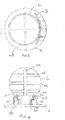
- An embodiment of check valve in accordance with the disclosure will now be described by way of example only with reference to the accompanying drawings in which:
-
Figure 1 shows a perspective view of a check valve in a fully open position; -
Figure 2 shows a perspective view of the check valve ofFigure 1 in a closed position; -
Figure 3 shows a top plan view of the check valve ofFigure 1 in the open position; -
Figure 4 shows a rear view of the check valve ofFigure 1 in the open position; -
Figure 5 shows a side view of the check valve ofFigure 1 in the open position; -
Figure 6 shows a top plan view of the check valve ofFigure 1 in the closed position; -
Figure 7 shows a side view of the check valve ofFigure 1 in the closed position; -
Figure 8 shows a rear view of the check valve ofFigure 1 in the closed position; -
Figure 9 shows a perspective view of the valve housing of the check valve ofFigure 1 ; -
Figure 10 shows a perspective view of the flapper element of the check valve ofFigure 1 ; -
Figure 11 shows an cross-sectional view along line A-A ofFigure 3 ; and -
Figure 12 shows a cross-sectional view along line B-B ofFigure 3 . - With reference to
Figure 1 , acheck valve 2 comprises avalve housing 4 and asingle flapper element 6 pivotally mounted to thevalve housing 4 at a proximal end 8 of theflapper element 6 through ahinge pin 10. In this embodiment, thevalve housing 4 is generally annular in shape, defining a generally circular valve opening 12 surrounded by a generallyannular flange 14. In use, theannular flange 14 will be suitably supported in a pipe or duct through which a fluid, for example a gas such as air flows. In alternative embodiments, theannular flange 14 may be integrally formed with a portion of the duct. The disclosure is not, limited to circularshapedhousings 4 and other housing shapes may be used. - The
flapper element 6 is pivotally mounted for rotation between a closed position shown for example inFigure 8 and a fully opened position shown for example inFigures 1 and5 . In the closed position, theflapper element 6 blocks the flow of fluid through thevalve opening 12. In the fully open position, and in intermediate positions, theflapper element 6 allows fluid to flow through thevalve opening 12. - As will be described further below, a pair of first
spring damping elements 16, and a secondspring damping element 18 are arranged between theflapper element 6 and thevalve housing 4 to damp the impact of theflapper element 6 on thevalve housing 4 as it moves to its fully open position. As will also be described, the first and secondspring damping elements flapper element 6 as it approaches its fully open position. - As can be seen in
Figure 1 andFigure 10 for example, theflapper element 6 comprises aflapper body 20 which, when viewed from above or below, is circular in shape for closing thevalve opening 12. The particular shape of theflapper body 20 will be determined by the shape of thevalve opening 12 and is not limited to a circular shape. Theflapper element 6 is generally symmetrical about its longitudinal centreline A. - The
flapper element 6 comprises a proximal end 8 by which it is mounted to thevalve housing 4. In this embodiment, the proximal end 8 comprises amounting portion 22 extending upwardly from theupper surface 24 of theflapper body 20 and aproximal extension 26 extending away from themounting portion 22 axially relative to the flapper element's centreline A. As can be seen, for example inFigures 4 ,8 and10 ,respective surfaces 28 are formed on the rearward surface of themounting portion 22 on either side of theproximal extension 26. Thesesurfaces 28 will opposecorresponding surfaces 60 in thevalve housing 4 when theflapper element 6 is in the fully open position. Thesurfaces 28 face rearwardly, i.e. away from theflapper body 20. In this particular embodiment they are arranged generally perpendicular to the plane of theflapper element 6. - In this embodiment, the
surface 28 is generally perpendicular to the plane of thevalve housing 4 when the flapper element is in the closed position. The mountingportion 22 further comprises a pair of hinge pins 30 projecting laterally therefrom in a direction generally perpendicular to the flapper element centreline A. The hinge pins 30 may be formed integrally with theflapper element 6 or formed as separate elements and suitably mounted to the mountingportion 22. In one example, the hinge pins 30 may be formed as end portions of an elongate pin projecting from both sides of the mountingportion 22. The hinge pins 30 may, for example, be insert moulded or insert cast into theflapper element 6 during manufacture of theflapper element 6. In yet further embodiment, the mountingportion 22 may be provided with a bore extending therethrough which pivotally receives ahinge pin 30. In a yet further arrangement, thehinge pin 30 may be provided with a flange and bolted or otherwise fastened to theflapper element 6. - The
proximal extension 26 is provided with abore 30 in its downwardly facingstop surface 32 for receiving the secondspring damping element 18. As illustrated in Figure 13, the secondspring damping element 18 comprises aspring element 34, for example a coil spring, and abumper element 36 which is slidably received in thebore 30. Thespring element 34 andbumper element 36 are retained in thebore 30 by means of afastening ring 38 which may, for example, be threadedly mounted in the mouth of thebore 30. Thebumper element 36 comprises a shoulder 40 which engages thefastening ring 38 when thebumper element 36 is biased fully outwardly of thebore 30 by thespring element 34, as shown inFigure 2 . Of course, thespring element 34 andbumper element 36 may be retained in thebore 30 by any suitable manner. The amount by which thebumper element 36 projects from thesurface 32 may be determined by appropriate sizing and/or positioning of thefastening ring 38 for example. As will be described further below, and as can be seen fromFigure 12 , when theflapper element 6 moves to its closed position, thebumper element 36 will move into contact with astop surface 70 of a raisedlip 48 of thevalve housing 4. Thedistal end 37 of thebumper element 36 may be rounded, as illustrated, to facilitate engagement with theopposed surface 70 of thevalve housing 4. - As can further be seen from
Figure 10 , for example, thebody 20 of theflapper element 6 is curved about its centreline A in a direction towards thevalve opening 12. Thus theflapper element 6 is arcuate, for example circularly arcuate, in a plane perpendicular to the centreline A. As will be described further below, this curvature may provide certain advantages. Theflapper body 20 is also provided with one ormore strengthening ribs 42 which extend along theupper surface 24 of theflapper body 20 in a direction generally perpendicular to the centreline A of theflapper body 20. In this embodiment, theribs 42 extend from a central, axially extendingrib 44 which extends generally parallel to the centreline A of theflapper body 20 from the mountingportion 22 of theflapper element 6. In this embodiment, the dimensions, for example the axial length of thecentral rib 44 may be chosen to provide an appropriate mass and thus moment of inertia for theflapper element 6. Thus, for example, thecentral rib 44 may, as illustrated, extend only over a proportion of the axial dimensional of theflapper element 6. In other embodiments, thecentral rib 44 may be simply replaced by a suitable point mass. Of course the shape, number and spatial arrangement of the strengtheningribs 42 may differ from that illustrated. - Turning now to the
valve housing 4, it can be seen, for example fromFigure 9 , that thevalve opening 12 is surrounded by a raisedlip 48 having a sealingsurface 50. The shape of the sealingsurface 50 is complementary to the shape of the periphery of theflapper body 20 so as to provide a seal between the two when theflapper element 6 is in the closed position. Thus, as can be seen inFigure 5 for example, the sealingsurface 50 slopes downwardly and outwardly relative to thevalve opening 12. - As discussed above, the
flapper element 6 is pivotally mounted to thevalve housing 4 by one or more hinge pins 30. Thevalve housing 4 comprises a pair of mountingposts 52 extending upwardly from theannular flange 14 of thevalve housing 4. As illustrated inFigure 9 , for example, the mountingposts 52 extend beyond the raisedlip 48 surrounding thevalve opening 12. Each mountingpost 52 comprises abore 54 which receives the hinge pin(s) 30 of theflapper element 6. As discussed above, the hinge pins 30 may be rotatably received within the mounting bores 54 or rotationally fixed with respect thereto, in which case, theflapper element 6 will pivot around thehinge pin 30. - For strength purposes, in this embodiment, the mounting
post 52 is formed contiguously with the raisedlip 48. However, that is not essential and it may be formed spaced therefrom. The mountingpost 52 is further provided with a laterally inwardly extendingportion 56, in this embodiment a shoulder, which, for strength purposes, is connected to thelip 48 by a web ofmaterial 58. Of course theportion 56 may be separate from the mountingpost 52 and/or the raisedlip 48. An upwardly facingsurface 60 is formed on the upper end of eachstop portion 56. In this embodiment, thesurface 60 is generally parallel to the plane of thevalve opening 12. - Each
portion 56 is also provided with abore 62 extending from thesurface 60. As can be seen inFigure 11 for example, thebore 62 receives a firstspring damping element 16. Thespring damping element 16 is similar in construction to the secondspring damping element 18 mounted in theflapper element 6, having abumper element 64 which is spring biased out of thebore 62 by aspring element 66, for example a coil spring as shown. Thebumper element 64 andspring element 66 may be retained in thebore 62 in a similar manner to the firstspring damping element 14 for example, or in any suitable manner. Also, the amount by which thebumper element 64 projects from thebore 62 may be set in a similar manner to that described above or some other suitable manner. Also, adistal end 65 of thebumper element 36 may be rounded, as illustrated. - Operation of the
check valve 2 will now be described. - As can be seen in
Figures 7 and 8 , when theflapper element 6 is in its closed position, the second dampingelement 16 projects downwardly from thesurface 32 of theproximal extension 28 of theflapper elements 6. Also, the firstspring damping elements 18 project upwardly from thesurfaces 60 of thevalve housing 4. In this position there is no contact between thespring damping elements flapper element 6 rotates from its closed position towards its fully open position, the second first dampingelement 16 first moves into contact with thestop surface portion 70 of the raisedlip 48 of thevalve housing 4 between the mounting posts 50. The precise rotational position at which the first dampingelement 16 contacts the raisedlip 48 can be determined by the amount by which the second dampingelement 16, more precisely itsbumper element 34 projects from thesurface 28. The particular rotational angle at which contact is made between thebumper element 38 and thesurface 28 can be chosen to provide the desired opening and damping characteristics. Typically, however, this contact may occur once theflapper element 6 has rotated to within 45°, for example within 30° or 20° of its fully closed position. The second dampingelement 18 thus begins to provide a damping force which begins to damp the movement of theflapper element 6. It will be appreciated that as there is no damping over the initial range of pivotal movement of theflapper element 6, theflapper element 6 is able to open quickly. - As the
flapper elements 6 continues to rotate, the firstspring damping elements 16 will contact thesurfaces 28 of theflapper element 6. This increases the damping force on theflapper element 6 as it moves to its fully open position. Again the precise position at which the firstspring damping elements 16 become effective can be determined by the amount they project from thestop surface 60 and can be chosen to provide the desired opening and damping characteristics. - The
spring damping elements - In this embodiment, the
springs 66 of the firstspring damping elements 16 have a higher spring constant than thesprings 32 of the secondspring damping element 18 such that they contribute the largest amount of damping force. The secondspring damping element 18 thus provides preliminary, relatively low damping. However, the relative spring constants may be chosen to give the desired damping profile. - In its fully open position, stop surfaces of the
flapper element 6 and thevalve housing 4 come into contact and thevalve 2 is maintained open by means of the pressure differential across thevalve 2. In the embodiment described, the downwardly facingsurface 32 of the flapper elementproximal extension 26 and thesurface portion 70 of thelip 48 of thevalve housing 4 form stop surfaces. However, it is also possible that in addition or alternatively thesurfaces 28 of the flappervalve mounting portion 22 and surfaces 60 of thevalve housing 4 may provide stop surfaces. - When the pressure differential across the
check valve 2 changes such that thecheck valve 2 will close, theflapper element 6 will biased towards the closed position by the first and secondspring damping elements check valve 2. - As the check valve moves to its closed position, the periphery of the
flapper body 20 will move into engagement with the sealingsurface 50 of thevalve housing lip 48. The curved form of theflapper body 20 may be advantageous in this regard in that it will allow theflapper body 20 to flex, thereby damping the impact of theflapper body 20 with the sealingsurface 50. - Whilst the embodiment described above has two sets of
spring damping elements check valve 2 may be provided with just one set ofspring damping elements spring damping element 18 may be omitted. In others, the firstspring damping elements 16 may be omitted or their number varied. It may be that the firstspring damping elements 16 are particularly advantageous, as thevalve housing 4 may provide a larger mass of material in which to mount the firstspring damping elements 16. - As discussed above, it will be seen that damping of the
flapper element 6 only occurs as theflapper element 6 approaches its fully open position. This allows rapid initial opening of thecheck valve 2. At the same time the spring force applied by thespring damping elements flapper element 6, also assisting rapid closure of thevalve 2. - The curved shape of the
flapper body 20 in this embodiment may also be advantageous, not only for the damping effect upon closure, but also as it will mitigate the possibility of theflapper element 6 interfering with the duct in which thecheck valve 2 is placed. Also, as illustrated inFigure 2 , the curved shape maximises the open flow area through thevalve opening 12, thereby reducing pressure losses through thecheck valve 2. - The described embodiment provides a
check valve 2 in which impact forces between theflapper element 6 and thevalve housing 4 are reduced due to thespring damping elements flapper element 6, thereby leading to improved operational life of thecheck valve 2.
Claims (16)
Priority Applications (2)
| Application Number | Priority Date | Filing Date | Title |
|---|---|---|---|
| EP17461551.8A EP3418611B1 (en) | 2017-06-21 | 2017-06-21 | Check valves |
| US16/014,286 US10794502B2 (en) | 2017-06-21 | 2018-06-21 | Check valves |
Applications Claiming Priority (1)
| Application Number | Priority Date | Filing Date | Title |
|---|---|---|---|
| EP17461551.8A EP3418611B1 (en) | 2017-06-21 | 2017-06-21 | Check valves |
Publications (2)
| Publication Number | Publication Date |
|---|---|
| EP3418611A1 true EP3418611A1 (en) | 2018-12-26 |
| EP3418611B1 EP3418611B1 (en) | 2020-04-22 |
Family
ID=59101428
Family Applications (1)
| Application Number | Title | Priority Date | Filing Date |
|---|---|---|---|
| EP17461551.8A Active EP3418611B1 (en) | 2017-06-21 | 2017-06-21 | Check valves |
Country Status (2)
| Country | Link |
|---|---|
| US (1) | US10794502B2 (en) |
| EP (1) | EP3418611B1 (en) |
Families Citing this family (3)
| Publication number | Priority date | Publication date | Assignee | Title |
|---|---|---|---|---|
| EP3667138B1 (en) * | 2018-12-10 | 2022-11-23 | Hamilton Sundstrand Corporation | Check valve |
| US11261980B2 (en) * | 2020-03-12 | 2022-03-01 | Coil Solutions, Inc. | Apparatus and method for activation of flapper check valve |
| CN215081861U (en) * | 2021-03-08 | 2021-12-10 | 南通荣威娱乐用品有限公司 | Jacuzzi Control Box and Jacuzzi |
Citations (3)
| Publication number | Priority date | Publication date | Assignee | Title |
|---|---|---|---|---|
| CN87202049U (en) * | 1987-02-10 | 1987-10-21 | 韩斌义 | Low-speed closing check |
| CN201273387Y (en) * | 2008-09-05 | 2009-07-15 | 广东联塑科技实业有限公司 | Check valve and its rocker |
| CN205371726U (en) * | 2016-01-20 | 2016-07-06 | 浙江纽沃阀门有限公司 | Swing check valve |
Family Cites Families (11)
| Publication number | Priority date | Publication date | Assignee | Title |
|---|---|---|---|---|
| US2454072A (en) * | 1944-08-04 | 1948-11-16 | Fred R Long | Combined pipe union and check valve |
| GB656332A (en) * | 1949-01-03 | 1951-08-22 | Havilland Engine Co Ltd | Improvements in or relating to rocket type propulsion apparatus |
| US5146949A (en) * | 1991-01-04 | 1992-09-15 | The Viking Corporation | Check valve with spring loaded clapper assembly |
| US5341840A (en) * | 1993-11-12 | 1994-08-30 | Tom Wheatley Valve Company | Bonnetless swing check valve |
| US7152622B2 (en) * | 2004-11-16 | 2006-12-26 | Valve Innovations, Llc | Check valve |
| ATE477026T1 (en) * | 2005-05-09 | 2010-08-15 | Rico Sicherheitstechnik Ag | EXPLOSION PROTECTION VALVE |
| US8317158B2 (en) | 2009-12-10 | 2012-11-27 | Honeywell International Inc. | Valve assemblies including corrugated flowbody and method for the manufacture thereof |
| US8887757B2 (en) * | 2012-03-12 | 2014-11-18 | Hayward Industries, Inc. | Wafer check valve assembly and related methods of use |
| CN105042124B (en) | 2015-08-12 | 2018-01-30 | 中国航空工业集团公司西安飞机设计研究所 | A kind of check valve device of catheter end head |
| CN205388173U (en) | 2015-12-31 | 2016-07-20 | 慎江阀门有限公司 | Built -in swing check valve that slowly closes |
| US9982793B2 (en) * | 2016-08-05 | 2018-05-29 | Tenneco Automotive Operating Company Inc. | Passive exhaust valve with dual torsion spring |
-
2017
- 2017-06-21 EP EP17461551.8A patent/EP3418611B1/en active Active
-
2018
- 2018-06-21 US US16/014,286 patent/US10794502B2/en active Active
Patent Citations (3)
| Publication number | Priority date | Publication date | Assignee | Title |
|---|---|---|---|---|
| CN87202049U (en) * | 1987-02-10 | 1987-10-21 | 韩斌义 | Low-speed closing check |
| CN201273387Y (en) * | 2008-09-05 | 2009-07-15 | 广东联塑科技实业有限公司 | Check valve and its rocker |
| CN205371726U (en) * | 2016-01-20 | 2016-07-06 | 浙江纽沃阀门有限公司 | Swing check valve |
Also Published As
| Publication number | Publication date |
|---|---|
| US10794502B2 (en) | 2020-10-06 |
| US20180372233A1 (en) | 2018-12-27 |
| EP3418611B1 (en) | 2020-04-22 |
Similar Documents
| Publication | Publication Date | Title |
|---|---|---|
| EP3001077B1 (en) | Anti-flutter check valve | |
| US10794502B2 (en) | Check valves | |
| US10344882B2 (en) | Check valve | |
| US11073300B2 (en) | Blast valve utilizing an aerodynamically configured blade | |
| EP3193059B1 (en) | Check valve | |
| EP3591272B1 (en) | Check valve | |
| EP3181965B1 (en) | Check valve | |
| US9347573B2 (en) | Check valve with reduced opening speed | |
| EP3023677B1 (en) | Check valves | |
| EP3181969B1 (en) | Check valve | |
| EP3220024B1 (en) | Check valve | |
| EP1988315A2 (en) | Fast acting aircraft engine bleed air check valve | |
| EP3960696A3 (en) | Breakaway assembly | |
| US8534314B2 (en) | Explosion protection valve | |
| US10393278B2 (en) | Check valve | |
| US10648581B2 (en) | Check valves | |
| US10167974B2 (en) | Check valves | |
| EP2233804A1 (en) | Butterfly valve combined with check valve | |
| US20040151599A1 (en) | Continuously blockable arresting device | |
| RU2661562C1 (en) | Check valve | |
| JPH0723868U (en) | Butterfly valve | |
| CN108895176B (en) | Spherical regulating valve | |
| JPH0798074A (en) | Emergency shutoff valve | |
| TH1901005437A (en) | Valve set, electric valve and refrigeration cycle system | |
| GB1585136A (en) | Flap valves |
Legal Events
| Date | Code | Title | Description |
|---|---|---|---|
| PUAI | Public reference made under article 153(3) epc to a published international application that has entered the european phase |
Free format text: ORIGINAL CODE: 0009012 |
|
| STAA | Information on the status of an ep patent application or granted ep patent |
Free format text: STATUS: THE APPLICATION HAS BEEN PUBLISHED |
|
| AK | Designated contracting states |
Kind code of ref document: A1 Designated state(s): AL AT BE BG CH CY CZ DE DK EE ES FI FR GB GR HR HU IE IS IT LI LT LU LV MC MK MT NL NO PL PT RO RS SE SI SK SM TR |
|
| AX | Request for extension of the european patent |
Extension state: BA ME |
|
| STAA | Information on the status of an ep patent application or granted ep patent |
Free format text: STATUS: REQUEST FOR EXAMINATION WAS MADE |
|
| 17P | Request for examination filed |
Effective date: 20190625 |
|
| RBV | Designated contracting states (corrected) |
Designated state(s): AL AT BE BG CH CY CZ DE DK EE ES FI FR GB GR HR HU IE IS IT LI LT LU LV MC MK MT NL NO PL PT RO RS SE SI SK SM TR |
|
| GRAP | Despatch of communication of intention to grant a patent |
Free format text: ORIGINAL CODE: EPIDOSNIGR1 |
|
| STAA | Information on the status of an ep patent application or granted ep patent |
Free format text: STATUS: GRANT OF PATENT IS INTENDED |
|
| INTG | Intention to grant announced |
Effective date: 20190806 |
|
| GRAS | Grant fee paid |
Free format text: ORIGINAL CODE: EPIDOSNIGR3 |
|
| GRAA | (expected) grant |
Free format text: ORIGINAL CODE: 0009210 |
|
| STAA | Information on the status of an ep patent application or granted ep patent |
Free format text: STATUS: THE PATENT HAS BEEN GRANTED |
|
| AK | Designated contracting states |
Kind code of ref document: B1 Designated state(s): AL AT BE BG CH CY CZ DE DK EE ES FI FR GB GR HR HU IE IS IT LI LT LU LV MC MK MT NL NO PL PT RO RS SE SI SK SM TR |
|
| REG | Reference to a national code |
Ref country code: CH Ref legal event code: EP |
|
| REG | Reference to a national code |
Ref country code: IE Ref legal event code: FG4D |
|
| REG | Reference to a national code |
Ref country code: DE Ref legal event code: R096 Ref document number: 602017015164 Country of ref document: DE |
|
| REG | Reference to a national code |
Ref country code: AT Ref legal event code: REF Ref document number: 1260552 Country of ref document: AT Kind code of ref document: T Effective date: 20200515 |
|
| REG | Reference to a national code |
Ref country code: LT Ref legal event code: MG4D |
|
| REG | Reference to a national code |
Ref country code: NL Ref legal event code: MP Effective date: 20200422 |
|
| PG25 | Lapsed in a contracting state [announced via postgrant information from national office to epo] |
Ref country code: PT Free format text: LAPSE BECAUSE OF FAILURE TO SUBMIT A TRANSLATION OF THE DESCRIPTION OR TO PAY THE FEE WITHIN THE PRESCRIBED TIME-LIMIT Effective date: 20200824 Ref country code: FI Free format text: LAPSE BECAUSE OF FAILURE TO SUBMIT A TRANSLATION OF THE DESCRIPTION OR TO PAY THE FEE WITHIN THE PRESCRIBED TIME-LIMIT Effective date: 20200422 Ref country code: LT Free format text: LAPSE BECAUSE OF FAILURE TO SUBMIT A TRANSLATION OF THE DESCRIPTION OR TO PAY THE FEE WITHIN THE PRESCRIBED TIME-LIMIT Effective date: 20200422 Ref country code: NL Free format text: LAPSE BECAUSE OF FAILURE TO SUBMIT A TRANSLATION OF THE DESCRIPTION OR TO PAY THE FEE WITHIN THE PRESCRIBED TIME-LIMIT Effective date: 20200422 Ref country code: SE Free format text: LAPSE BECAUSE OF FAILURE TO SUBMIT A TRANSLATION OF THE DESCRIPTION OR TO PAY THE FEE WITHIN THE PRESCRIBED TIME-LIMIT Effective date: 20200422 Ref country code: IS Free format text: LAPSE BECAUSE OF FAILURE TO SUBMIT A TRANSLATION OF THE DESCRIPTION OR TO PAY THE FEE WITHIN THE PRESCRIBED TIME-LIMIT Effective date: 20200822 Ref country code: NO Free format text: LAPSE BECAUSE OF FAILURE TO SUBMIT A TRANSLATION OF THE DESCRIPTION OR TO PAY THE FEE WITHIN THE PRESCRIBED TIME-LIMIT Effective date: 20200722 Ref country code: GR Free format text: LAPSE BECAUSE OF FAILURE TO SUBMIT A TRANSLATION OF THE DESCRIPTION OR TO PAY THE FEE WITHIN THE PRESCRIBED TIME-LIMIT Effective date: 20200723 |
|
| REG | Reference to a national code |
Ref country code: AT Ref legal event code: MK05 Ref document number: 1260552 Country of ref document: AT Kind code of ref document: T Effective date: 20200422 |
|
| PG25 | Lapsed in a contracting state [announced via postgrant information from national office to epo] |
Ref country code: HR Free format text: LAPSE BECAUSE OF FAILURE TO SUBMIT A TRANSLATION OF THE DESCRIPTION OR TO PAY THE FEE WITHIN THE PRESCRIBED TIME-LIMIT Effective date: 20200422 Ref country code: RS Free format text: LAPSE BECAUSE OF FAILURE TO SUBMIT A TRANSLATION OF THE DESCRIPTION OR TO PAY THE FEE WITHIN THE PRESCRIBED TIME-LIMIT Effective date: 20200422 Ref country code: LV Free format text: LAPSE BECAUSE OF FAILURE TO SUBMIT A TRANSLATION OF THE DESCRIPTION OR TO PAY THE FEE WITHIN THE PRESCRIBED TIME-LIMIT Effective date: 20200422 Ref country code: BG Free format text: LAPSE BECAUSE OF FAILURE TO SUBMIT A TRANSLATION OF THE DESCRIPTION OR TO PAY THE FEE WITHIN THE PRESCRIBED TIME-LIMIT Effective date: 20200722 |
|
| PG25 | Lapsed in a contracting state [announced via postgrant information from national office to epo] |
Ref country code: AL Free format text: LAPSE BECAUSE OF FAILURE TO SUBMIT A TRANSLATION OF THE DESCRIPTION OR TO PAY THE FEE WITHIN THE PRESCRIBED TIME-LIMIT Effective date: 20200422 |
|
| REG | Reference to a national code |
Ref country code: DE Ref legal event code: R119 Ref document number: 602017015164 Country of ref document: DE |
|
| PG25 | Lapsed in a contracting state [announced via postgrant information from national office to epo] |
Ref country code: ES Free format text: LAPSE BECAUSE OF FAILURE TO SUBMIT A TRANSLATION OF THE DESCRIPTION OR TO PAY THE FEE WITHIN THE PRESCRIBED TIME-LIMIT Effective date: 20200422 Ref country code: MC Free format text: LAPSE BECAUSE OF FAILURE TO SUBMIT A TRANSLATION OF THE DESCRIPTION OR TO PAY THE FEE WITHIN THE PRESCRIBED TIME-LIMIT Effective date: 20200422 Ref country code: SM Free format text: LAPSE BECAUSE OF FAILURE TO SUBMIT A TRANSLATION OF THE DESCRIPTION OR TO PAY THE FEE WITHIN THE PRESCRIBED TIME-LIMIT Effective date: 20200422 Ref country code: EE Free format text: LAPSE BECAUSE OF FAILURE TO SUBMIT A TRANSLATION OF THE DESCRIPTION OR TO PAY THE FEE WITHIN THE PRESCRIBED TIME-LIMIT Effective date: 20200422 Ref country code: DK Free format text: LAPSE BECAUSE OF FAILURE TO SUBMIT A TRANSLATION OF THE DESCRIPTION OR TO PAY THE FEE WITHIN THE PRESCRIBED TIME-LIMIT Effective date: 20200422 Ref country code: IT Free format text: LAPSE BECAUSE OF FAILURE TO SUBMIT A TRANSLATION OF THE DESCRIPTION OR TO PAY THE FEE WITHIN THE PRESCRIBED TIME-LIMIT Effective date: 20200422 Ref country code: RO Free format text: LAPSE BECAUSE OF FAILURE TO SUBMIT A TRANSLATION OF THE DESCRIPTION OR TO PAY THE FEE WITHIN THE PRESCRIBED TIME-LIMIT Effective date: 20200422 Ref country code: AT Free format text: LAPSE BECAUSE OF FAILURE TO SUBMIT A TRANSLATION OF THE DESCRIPTION OR TO PAY THE FEE WITHIN THE PRESCRIBED TIME-LIMIT Effective date: 20200422 Ref country code: CZ Free format text: LAPSE BECAUSE OF FAILURE TO SUBMIT A TRANSLATION OF THE DESCRIPTION OR TO PAY THE FEE WITHIN THE PRESCRIBED TIME-LIMIT Effective date: 20200422 |
|
| REG | Reference to a national code |
Ref country code: CH Ref legal event code: PL |
|
| PG25 | Lapsed in a contracting state [announced via postgrant information from national office to epo] |
Ref country code: PL Free format text: LAPSE BECAUSE OF FAILURE TO SUBMIT A TRANSLATION OF THE DESCRIPTION OR TO PAY THE FEE WITHIN THE PRESCRIBED TIME-LIMIT Effective date: 20200422 Ref country code: SK Free format text: LAPSE BECAUSE OF FAILURE TO SUBMIT A TRANSLATION OF THE DESCRIPTION OR TO PAY THE FEE WITHIN THE PRESCRIBED TIME-LIMIT Effective date: 20200422 |
|
| PLBE | No opposition filed within time limit |
Free format text: ORIGINAL CODE: 0009261 |
|
| STAA | Information on the status of an ep patent application or granted ep patent |
Free format text: STATUS: NO OPPOSITION FILED WITHIN TIME LIMIT |
|
| 26N | No opposition filed |
Effective date: 20210125 |
|
| PG25 | Lapsed in a contracting state [announced via postgrant information from national office to epo] |
Ref country code: LU Free format text: LAPSE BECAUSE OF NON-PAYMENT OF DUE FEES Effective date: 20200621 |
|
| REG | Reference to a national code |
Ref country code: BE Ref legal event code: MM Effective date: 20200630 |
|
| PG25 | Lapsed in a contracting state [announced via postgrant information from national office to epo] |
Ref country code: IE Free format text: LAPSE BECAUSE OF NON-PAYMENT OF DUE FEES Effective date: 20200621 Ref country code: CH Free format text: LAPSE BECAUSE OF NON-PAYMENT OF DUE FEES Effective date: 20200630 Ref country code: LI Free format text: LAPSE BECAUSE OF NON-PAYMENT OF DUE FEES Effective date: 20200630 |
|
| PG25 | Lapsed in a contracting state [announced via postgrant information from national office to epo] |
Ref country code: BE Free format text: LAPSE BECAUSE OF NON-PAYMENT OF DUE FEES Effective date: 20200630 Ref country code: DE Free format text: LAPSE BECAUSE OF NON-PAYMENT OF DUE FEES Effective date: 20210101 Ref country code: SI Free format text: LAPSE BECAUSE OF FAILURE TO SUBMIT A TRANSLATION OF THE DESCRIPTION OR TO PAY THE FEE WITHIN THE PRESCRIBED TIME-LIMIT Effective date: 20200422 |
|
| PG25 | Lapsed in a contracting state [announced via postgrant information from national office to epo] |
Ref country code: TR Free format text: LAPSE BECAUSE OF FAILURE TO SUBMIT A TRANSLATION OF THE DESCRIPTION OR TO PAY THE FEE WITHIN THE PRESCRIBED TIME-LIMIT Effective date: 20200422 Ref country code: MT Free format text: LAPSE BECAUSE OF FAILURE TO SUBMIT A TRANSLATION OF THE DESCRIPTION OR TO PAY THE FEE WITHIN THE PRESCRIBED TIME-LIMIT Effective date: 20200422 Ref country code: CY Free format text: LAPSE BECAUSE OF FAILURE TO SUBMIT A TRANSLATION OF THE DESCRIPTION OR TO PAY THE FEE WITHIN THE PRESCRIBED TIME-LIMIT Effective date: 20200422 |
|
| PG25 | Lapsed in a contracting state [announced via postgrant information from national office to epo] |
Ref country code: MK Free format text: LAPSE BECAUSE OF FAILURE TO SUBMIT A TRANSLATION OF THE DESCRIPTION OR TO PAY THE FEE WITHIN THE PRESCRIBED TIME-LIMIT Effective date: 20200422 |
|
| P01 | Opt-out of the competence of the unified patent court (upc) registered |
Effective date: 20230522 |
|
| PGFP | Annual fee paid to national office [announced via postgrant information from national office to epo] |
Ref country code: GB Payment date: 20250520 Year of fee payment: 9 |
|
| PGFP | Annual fee paid to national office [announced via postgrant information from national office to epo] |
Ref country code: FR Payment date: 20250520 Year of fee payment: 9 |