EP3418603A1 - Damping devices, systems and methods for hollow shafts, struts, and beams with bending modes - Google Patents
Damping devices, systems and methods for hollow shafts, struts, and beams with bending modes Download PDFInfo
- Publication number
- EP3418603A1 EP3418603A1 EP18184389.7A EP18184389A EP3418603A1 EP 3418603 A1 EP3418603 A1 EP 3418603A1 EP 18184389 A EP18184389 A EP 18184389A EP 3418603 A1 EP3418603 A1 EP 3418603A1
- Authority
- EP
- European Patent Office
- Prior art keywords
- damping
- structural component
- tube member
- vibration
- damping element
- Prior art date
- Legal status (The legal status is an assumption and is not a legal conclusion. Google has not performed a legal analysis and makes no representation as to the accuracy of the status listed.)
- Granted
Links
Images



Classifications
-
- F—MECHANICAL ENGINEERING; LIGHTING; HEATING; WEAPONS; BLASTING
- F16—ENGINEERING ELEMENTS AND UNITS; GENERAL MEASURES FOR PRODUCING AND MAINTAINING EFFECTIVE FUNCTIONING OF MACHINES OR INSTALLATIONS; THERMAL INSULATION IN GENERAL
- F16F—SPRINGS; SHOCK-ABSORBERS; MEANS FOR DAMPING VIBRATION
- F16F15/00—Suppression of vibrations in systems; Means or arrangements for avoiding or reducing out-of-balance forces, e.g. due to motion
- F16F15/10—Suppression of vibrations in rotating systems by making use of members moving with the system
- F16F15/12—Suppression of vibrations in rotating systems by making use of members moving with the system using elastic members or friction-damping members, e.g. between a rotating shaft and a gyratory mass mounted thereon
- F16F15/121—Suppression of vibrations in rotating systems by making use of members moving with the system using elastic members or friction-damping members, e.g. between a rotating shaft and a gyratory mass mounted thereon using springs as elastic members, e.g. metallic springs
- F16F15/124—Elastomeric springs
- F16F15/126—Elastomeric springs consisting of at least one annular element surrounding the axis of rotation
-
- F—MECHANICAL ENGINEERING; LIGHTING; HEATING; WEAPONS; BLASTING
- F16—ENGINEERING ELEMENTS AND UNITS; GENERAL MEASURES FOR PRODUCING AND MAINTAINING EFFECTIVE FUNCTIONING OF MACHINES OR INSTALLATIONS; THERMAL INSULATION IN GENERAL
- F16F—SPRINGS; SHOCK-ABSORBERS; MEANS FOR DAMPING VIBRATION
- F16F7/00—Vibration-dampers; Shock-absorbers
- F16F7/08—Vibration-dampers; Shock-absorbers with friction surfaces rectilinearly movable along each other
- F16F7/09—Vibration-dampers; Shock-absorbers with friction surfaces rectilinearly movable along each other in dampers of the cylinder-and-piston type
- F16F7/095—Vibration-dampers; Shock-absorbers with friction surfaces rectilinearly movable along each other in dampers of the cylinder-and-piston type frictional elements brought into engagement by movement along a surface oblique to the axis of the cylinder, e.g. interaction of wedge-shaped elements
-
- F—MECHANICAL ENGINEERING; LIGHTING; HEATING; WEAPONS; BLASTING
- F16—ENGINEERING ELEMENTS AND UNITS; GENERAL MEASURES FOR PRODUCING AND MAINTAINING EFFECTIVE FUNCTIONING OF MACHINES OR INSTALLATIONS; THERMAL INSULATION IN GENERAL
- F16F—SPRINGS; SHOCK-ABSORBERS; MEANS FOR DAMPING VIBRATION
- F16F15/00—Suppression of vibrations in systems; Means or arrangements for avoiding or reducing out-of-balance forces, e.g. due to motion
- F16F15/02—Suppression of vibrations of non-rotating, e.g. reciprocating systems; Suppression of vibrations of rotating systems by use of members not moving with the rotating systems
-
- F—MECHANICAL ENGINEERING; LIGHTING; HEATING; WEAPONS; BLASTING
- F16—ENGINEERING ELEMENTS AND UNITS; GENERAL MEASURES FOR PRODUCING AND MAINTAINING EFFECTIVE FUNCTIONING OF MACHINES OR INSTALLATIONS; THERMAL INSULATION IN GENERAL
- F16F—SPRINGS; SHOCK-ABSORBERS; MEANS FOR DAMPING VIBRATION
- F16F15/00—Suppression of vibrations in systems; Means or arrangements for avoiding or reducing out-of-balance forces, e.g. due to motion
- F16F15/10—Suppression of vibrations in rotating systems by making use of members moving with the system
- F16F15/12—Suppression of vibrations in rotating systems by making use of members moving with the system using elastic members or friction-damping members, e.g. between a rotating shaft and a gyratory mass mounted thereon
- F16F15/1207—Suppression of vibrations in rotating systems by making use of members moving with the system using elastic members or friction-damping members, e.g. between a rotating shaft and a gyratory mass mounted thereon characterised by the supporting arrangement of the damper unit
-
- F—MECHANICAL ENGINEERING; LIGHTING; HEATING; WEAPONS; BLASTING
- F16—ENGINEERING ELEMENTS AND UNITS; GENERAL MEASURES FOR PRODUCING AND MAINTAINING EFFECTIVE FUNCTIONING OF MACHINES OR INSTALLATIONS; THERMAL INSULATION IN GENERAL
- F16F—SPRINGS; SHOCK-ABSORBERS; MEANS FOR DAMPING VIBRATION
- F16F15/00—Suppression of vibrations in systems; Means or arrangements for avoiding or reducing out-of-balance forces, e.g. due to motion
- F16F15/10—Suppression of vibrations in rotating systems by making use of members moving with the system
- F16F15/12—Suppression of vibrations in rotating systems by making use of members moving with the system using elastic members or friction-damping members, e.g. between a rotating shaft and a gyratory mass mounted thereon
- F16F15/129—Suppression of vibrations in rotating systems by making use of members moving with the system using elastic members or friction-damping members, e.g. between a rotating shaft and a gyratory mass mounted thereon characterised by friction-damping means
- F16F15/1292—Suppression of vibrations in rotating systems by making use of members moving with the system using elastic members or friction-damping members, e.g. between a rotating shaft and a gyratory mass mounted thereon characterised by friction-damping means characterised by arrangements for axially clamping or positioning or otherwise influencing the frictional plates
-
- F—MECHANICAL ENGINEERING; LIGHTING; HEATING; WEAPONS; BLASTING
- F16—ENGINEERING ELEMENTS AND UNITS; GENERAL MEASURES FOR PRODUCING AND MAINTAINING EFFECTIVE FUNCTIONING OF MACHINES OR INSTALLATIONS; THERMAL INSULATION IN GENERAL
- F16F—SPRINGS; SHOCK-ABSORBERS; MEANS FOR DAMPING VIBRATION
- F16F15/00—Suppression of vibrations in systems; Means or arrangements for avoiding or reducing out-of-balance forces, e.g. due to motion
- F16F15/10—Suppression of vibrations in rotating systems by making use of members moving with the system
- F16F15/14—Suppression of vibrations in rotating systems by making use of members moving with the system using masses freely rotating with the system, i.e. uninvolved in transmitting driveline torque, e.g. rotative dynamic dampers
- F16F15/1407—Suppression of vibrations in rotating systems by making use of members moving with the system using masses freely rotating with the system, i.e. uninvolved in transmitting driveline torque, e.g. rotative dynamic dampers the rotation being limited with respect to the driving means
- F16F15/1414—Masses driven by elastic elements
-
- F—MECHANICAL ENGINEERING; LIGHTING; HEATING; WEAPONS; BLASTING
- F16—ENGINEERING ELEMENTS AND UNITS; GENERAL MEASURES FOR PRODUCING AND MAINTAINING EFFECTIVE FUNCTIONING OF MACHINES OR INSTALLATIONS; THERMAL INSULATION IN GENERAL
- F16F—SPRINGS; SHOCK-ABSORBERS; MEANS FOR DAMPING VIBRATION
- F16F7/00—Vibration-dampers; Shock-absorbers
- F16F7/02—Vibration-dampers; Shock-absorbers with relatively-rotatable friction surfaces that are pressed together
- F16F7/06—Vibration-dampers; Shock-absorbers with relatively-rotatable friction surfaces that are pressed together in a direction perpendicular or inclined to the axis of rotation
Definitions
- the subject matter herein relates generally to devices, systems, and methods for damping vibration.
- the subject matter herein more particularly relates to devices, systems, and methods for damping the resonant amplitude of beaming and/or torsional modes of vibration associated with a structural component.
- Structural components including shafts, struts, and beams, are used in a variety of different applications, for example, in frames or mounts for supporting, equipment or machinery.
- Individual shafts and/or struts are typically hollow, which allows manufacturers and/or operators to benefit from reductions in cost and/or weight, for example, especially in regards to vehicle (e.g., aircraft, automobile, etc.) systems.
- Rotating components within the supported machinery e.g., engines, motors, rotors, propellers, or the like
- this vibration can excite flexural and torsional beaming modes of vibration imparted to individual struts within a frame or mount.
- hollow rotating shafts, supported within bearings are used for power-transmission in various types of machinery. In these applications, operational angular velocities near or through the shaft's critical speed range can induce resonant vibration throughout the shaft and equipment.
- Conventional methods of reducing vibration within a structural component or power transmission shaft include either designing a component that will have a suitable margin or thickness between the rotating structure and the individual structural component, or providing a tuned mass for altering the tuning of the structural component. Conventional methods are problematic, however, as adding margins and/or tuned masses will increase the weight of the structural component, which is undesirable.
- An exemplary damping device includes a tube member comprising a first end and a second end.
- a first damping element is disposed on the first end of the tube member and a second damping element disposed at the second end of the tube member.
- the first and second damping elements are configured to flex against a structural component for dissipating energy from the structural component and for reducing the bending of the structural component due to modal characteristics induced by vibration.
- damping devices herein are configured to physically contact the structural component in three discrete locations, or less. Damping devices herein are configured to physically contact the structural component in a location proximate a center of a longitudinal axis of the structural component. Damping devices herein comprise a length that is between about 10% and about 80% of the length of the structural component. Damping devices herein are attached to a structural component via a retention ring, a clamp, adhesive, brazing, or welding.
- An exemplary damping system comprises a hollow structural component and a damping device disposed inside the hollow structural component.
- the damping device comprises a tube member that is concentric with the structural component or power transmission shaft and at least one damping element attached to a portion of the tube member.
- the damping element is disposed between portions of an inner wall of the structural component and the tube member.
- the damping element is configured to dissipate vibration and reduce bending of the structural component due to modal characteristics excited by vibration of the supported equipment or rotating shaft.
- the damping device physically contacts the inner wall of the structural component in three discrete contact points or less.
- An exemplary method of damping vibration includes providing a tube member comprising a first end and a second end, attaching a first damping element to the first end of the tube member, and attaching a second damping element to the second end of the tube member.
- the method further includes flexing the first and second damping elements against a structural component or power-transmission shaft for dissipating energy from the component and for reducing the bending of the component due to modal characteristics excited by vibration.
- damping devices herein include damping elements comprising a viscoelastic material, such as silicone.
- damping elements include a spring element that is configured to clamp a friction element to an insert element to generate a frictional force to damp vibration.
- damping elements include a metallic mesh for higher temperature resistance.
- the damping elements are each configured to flex against an inner wall of the structural component.
- a damping device comprises a structural component, a tube member, a first damping element, and a second damping element.
- the tube member is disposed inside of the structural component, the tube member having a first end and a second end.
- the first damping element is disposed on the first end of the tube member.
- the second damping element is disposed on the second end of the tube member.
- the first damping element and the second damping element are configured to flex against the structural component for dissipating energy from the structural component and for reducing the bending of the structural component due to modal characteristics induced by vibration.
- the damping device physically contacts the structural component in three discrete locations (I, II, III) or less.
- the damping device physically contacts the structural component in a location (II) proximate a center (C L ) of a longitudinal axis of the structural component.
- the tube member comprises a length that is between about 10% and about 80% of the length of the structural component.
- at least one of the first and second damping elements comprises silicone.
- at least one of the first and second damping elements comprises a spring element that is configured to clamp a friction element to an insert element to generate a frictional force to damp vibration.
- at least one of the first and second damping elements comprise a metallic mesh for higher temperature resistance.
- the first damping element and the second damping element are configured to flex against an inner wall of the structural component.
- the tube member is attached to the structural component via a retention ring, a clamp, adhesive, brazing, or welding.
- a damping system comprises a structural component, and a damping device.
- the structural component comprising at least one inner wall, the structural component being hollow.
- the damping device is disposed within the structural component.
- the damping device further comprises a tube member and at least one damping element.
- the tube member is concentric with the structural component.
- the at least one damping element is attached to a portion of the tube member, wherein the damping element is disposed between portions of the inner wall of the structural component and the tube member.
- the damping element is configured to dissipate vibration and reduce bending of the structural component due to modal characteristics induced by vibration of the structural component.
- the system comprises having the damping device physically contacts the inner wall of the structural component in at least two or more contact points (I, II). In one embodiment, the system comprises having at least a one contact point (II) proximate a center (C L ) of a longitudinal axis of the structural component. In one embodiment, the system further comprises a first and second damping elements disposed on opposing ends of the tube member. In one embodiment, the tube member comprises a length that is between about 10% and about 80% of the length of the structural component. In one embodiment, the at least one damping element comprises silicone. In one embodiment, the at least one damping element comprises a spring element that is configured to clamp a friction element to an insert element for generating a frictional force to damp vibration. In one embodiment, the at least one damping element comprises a metallic mesh. In one embodiment, the at least one damping element is configured to reduce a resonant amplitude of at least a first bending mode of the structural component.
- a method of vibration damping includes the steps of:
- the method further comprises positioning the damping device inside of the structural component so that the damping device physically contacts the structural component at least three discrete locations (I, II, III). In one embodiment, the method further comprises positioning the damping device inside of the structural component so that the damping device physically contacts the structural component in a location (II) that is proximate a center (C L ) of a longitudinal axis of the structural component.
- Damping devices, systems, and methods herein reduce the resonant amplitude of the first several beaming modes and/or torsional modes of a hollow shaft or strut.
- FIGS. 1A to 4 illustrate various views, embodiments, and/or aspects associated with vibration damping devices, systems, and related methods by which the life of structural components associated with rotating machinery or equipment may be extended.
- devices, systems, and methods herein dissipate vibrational energy via the addition of stiffness and/or damping to a structural component, such as a hollow strut or shaft.
- Devices, systems, and methods herein are configured to reduce the resonant transmissibility associated with torsional modes and/or one or more primary bending modes of a structural component (e.g., a fixed shaft, strut, or beam).
- the thickness of many shafts, struts, or beams, which were originally designed according to fatigue strength through resonance, may be reduced when vibrations are effectively damped.
- devices, systems, and methods herein provide a strut-and-damper assembly, which may advantageously be lighter-weight than the original strut.
- Devices, systems, and methods set forth herein may be used in many different applications, not limited to use within structural components and/or structural component systems, such as, for example, rotating shafts (e.g., operating near a critical speed or accelerating through a critical speed), airframe struts, auxiliary power unit supports, support frame components, engine attachment supports and frame components, attach frame components, engine mount components, drive shafts (e.g., for vehicles not limited to aircraft and/or automobiles), high-speed internal shafts within engines, power transmission shafts in high-speed rotating equipment, vehicle systems, engine systems, or the like.
- rotating shafts e.g., operating near a critical speed or accelerating through a critical speed
- airframe struts e.g., airframe struts
- auxiliary power unit supports e.g., support frame components, engine attachment supports and frame components, attach frame components, engine mount components, drive shafts (e.g., for vehicles not limited to aircraft and/or automobiles), high-speed internal shafts within engines, power
- Damper devices, systems, and methods herein may comprise internal damping devices, suited for damping vibration and/or resonant amplitude of various structural components such as shafts, struts, frame members, and/or beams.
- devices, systems, and methods herein can be used address the torsional mode (twist) of the structural component along with the primary bending or beaming modes.
- FIGS. 1A-4 several non-limiting, exemplary embodiments of damping devices, systems, and methods are illustrated. As each of the figures is exemplary, some elements and/or the functionality thereof may be combined, separated, integrated, and/or modified while remaining within the scope of the claims.
- damping system 100 includes at least one structural component 101 and a damping device, generally designated 200 .
- structural component 101 includes a strut, shaft, a beam, or the like.
- Damping device 200 may include an internal damping device, which is configured to attach or connect to the structural component and in some embodiments, is inserted therein and/or integrated therewith. Damping device 200 includes a first end E 1 and a second end E 2 opposing the first end.
- FIG. 1A is a perspective view of a structural component 101 , such as a beam, a strut, a bar, or a shaft, having a component body 104 disposed between a first end 102A and a second end 102B .
- Structural component 101 may be used alone and/or in combination with one or more additional structural components 101 to form a frame or mounting structure for supporting and/or mounting portions of a machine with vibration-producing sources (not shown, e.g., an engine, rotor, propeller, drive shaft, rotating shaft, etc.).
- First and second ends 102A and 102B may include end fittings that are fixedly attached or connected to one or more additional structures (not shown) for supporting body 104 therebetween.
- each end (e.g., 102A , 102B ) include eye-bolts, fasteners, pins, clips, hooks, screws, twist-lock fittings, snap on fittings, or any other type of fittings or fastening structures.
- first and second ends 102A and 102B may independently connect and/or affix to a fixed support structure for an engine mount, a fixed machine component, a fixed housing (e.g., an engine housing), etc.
- body 104 exhibits or experiences one or more resonant beaming modes (e.g., bending and/or torsional modes) when vibrations are transferred thereto from the supported equipment (not shown). Damping devices, systems, and methods herein are configured to reduce the resonant transmissibility associated with one or more primary beaming modes and/or torsional modes acting on a structural component body 104 .
- body 104 includes a primary shaft, strut, beam, bar, or tube that is configured to receive (e.g., internally) a secondary damping tube in the form of a damping device 200 ( FIG. 1B ).
- Body 104 may be formed of any material including but not limited to metal, a metal alloy, steel, aluminum (Al), plastic, any rigid material, any flexible material, any composite material, or the like.
- FIG. 1B is a sectional view of system 100 taken longitudinally between first and second ends 102A and 102B of FIG. 1A .
- the structural component 101 may include a hollow body 104 .
- a damping device 200 is positioned or otherwise disposed within a portion of body 104, for example, between one or more inner walls 104A of structural component 101 and/or body 104 .
- Damping device 200 is configured to physically contact body 104 (e.g., inner walls 104A of body 104 ) in at least two or more locations.
- device 200 may contact body 104 in at least three locations, generally designated I , II , and III .
- the number of contact points or contact locations (e.g., I , II , III ) between device 200 and body 104 of structural component 101 depends upon the length and/or diameter of body 104 , and is not limited to any specific number of contact points or contact locations.
- device 200 comprises a tubular (cylindrical) shaped body or tube member 202 that is disposed within body 104 of a hollow shaft or strut.
- tube member 202 and body 104 are concentric structures having a same centerline, center plane, center point, or center axis (any of a center x, y, or z-axis).
- body 104 is referred to as a "primary" tube and tube member 202 is referred to as a "secondary" tube within damping system 100 .
- Tube member 202 may include a stiff and/or rigid structure having an outer diameter that is smaller than an inner diameter of body 104 , and can contact or connect to body 104 via a retaining structure or retaining ring, generally designated 204 .
- retaining ring 204 includes one or more annular rings (e.g., 204A , 204B , FIG. 1C ) disposed about an outermost diameter of tube member 202 .
- Retaining ring 204 can comprise one or more components that are configured to clamp a portion of device 200 to body 104 and/or frictionally retain device 200 against inner walls 104A ( FIG. 1C ) of body 104 .
- Retaining ring 204 may comprise a single retaining structure (e.g., ring) or a plurality of retaining structures (e.g., rings).
- retaining ring 204 is disposed proximate a centerline or a central axis of tube member 202 and body 104 , for example, along a centerline that bisects each tube (e.g., 202 and 104 ) along the respective longitudinal length into two substantially equal portions having a substantially same dimension.
- Retaining ring 204 may include a single annular member or multiple annular members configured to retain device 200 against one or more inner walls 104A of body 104 , the members may overlap and/or be spaced apart from each other during retention of device 200 against inner wall 104A , potentially incorporating self-locking taper angles.
- retaining ring 204 is exemplary and optional, as an adhesive and/or interference fit component, press fit component, etc. may be provided between tube member 202 and body 104 to connect tube member 202 to body 104 .
- tube member 202 of device 200 may be secured to body 104 via adhesive, one or more mechanical fasteners (e.g., pins, hooks, screws, etc.), one or more frictional fasteners, one or more press fit components, soldering, brazing, welding, or the like.
- retaining ring 204 comprises at least one tapered clamp ring. Where a metal damper tube member 202 is used, brazing, soldering, and/or welding may be used to attach the damper tube (e.g., tube member 202 ) to the primary tube (e.g., body 104 ).
- damping device 200 is configured to contact body 104 at a first location I and a third location III via one or more damping devices or elements, in some embodiments, at least a first damping element 208A and a second damping element 208B .
- Each damping element e.g., 208A and 208B
- each damping element may include a viscoelastic component, a metal component, a metal alloy component, a frictional spring damping component, an elastomer component, a plastic component, a wire mesh component or material, a friction-inducing element or component or material, a single discrete damping component, a multi-layered component, or the like.
- First and second damping elements 208A and 208B may each comprise a same size, shape, structure, and/or material; or first damping element 208A can comprise a different size, shape, structure, and/or material than the other, second damping element 208B .
- each damping element e.g., 208A and 208B
- each damping element is configured to dissipate energy (e.g., mechanical energy, vibrational energy, or the like) via flexing in response to vibrations and/or bending imparted to the body 104 .
- each damping element e.g., 208A and 208B
- first and second damping elements 208A and 208B proximate opposing ends E 1 and E 2 of tube member 202 and/or body 104 can advantageously allow such elements or components to be readily installed and/or replaced as needed, while still providing effective damping when in an installed state.
- more than two, or less than two damping elements may also be provided.
- damping device 200 is configured to contact body 104 at a second, centralized location II via retaining ring 104 or other retaining structure and/or retaining material. In some embodiments, damping device 200 only contacts body 104 at three locations. In other embodiments, damping device 200 contacts body 104 at more than three locations (e.g., where a longer body 104 is provided) or at less than three locations (e.g., where a shorter body 104 is provided).
- the length of damping device 200 as compared to the length of body 104 may be optimized or improved as desired, for example, based upon factors including the amount of damping desired, the type of damping desired (e.g., resonant, torsional), the beaming mode, and/or the damping environment (e.g., thermal environment, chemical environment, etc.).
- the damping environment e.g., thermal environment, chemical environment, etc.
- tube member 202 is a stiff and/or substantially rigid body of material comprising a metal, a metal alloy, steel, Al, plastic, a composite material, or any other stiff, lightweight material. Tube member 202 may also be hollow for facilitating weight reduction of system 100 . Damping device 200 may be configured to dissipate energy via the addition of both stiffness and damping, which can collectively and effectively reduce the resonant amplitude at which body 104 is vibrating.
- a length of device 200 ranges from about 10% to about 80% of the length of the overall, original body 104 (e.g., not including ends 102A and 102B ).
- the length of device 200 and respective tube member 202 can be validated, optimized, and/or set to any value, where desired.
- body 104 is about 24 inches (about 61 centimeters) long and tube member 202 can range in length from about 4.8 inches to about 20 inches (about 12.2 centimeters to about 51 centimeters). Any length of body 104 and/or tube member 202 can be provided. Similarly, any ratio between the length of body 104 and tube member 202 can be provided.
- body 104 and tube member 202 comprise concentric and cylindrical annular-shaped shells, wherein body 104 fully encases and/or surrounds tube member 202 .
- a non-limiting ratio between a length (L B ) of body 104 and a length (L T ) of tube member 202 may include a ratio (L B/ L T) of about 0.5 or more, about 1.0 or more, about 1.3 or more, about 2.0 or more, about 3.0 or more, about 4.0 or more, about 5.0 or more, or the like.
- damping element 208A is illustrated as being secured to tube member 202 via an end fitting or adapter 206 .
- Adapter 206 may include a body of metal or a metal alloy configured to isolate a respective damping element (e.g., 208A and 208B ) and connect the damping element to outermost, opposing ends of tube member 202 .
- FIG. 1C is an enhanced (closer) view of one-half of system 100 and device 200 as shown in FIG. 1B , with the opposing side (not shown) being a mirror image of that shown.
- a retaining member 210 and a securing element 212 can further isolate each damping element (e.g., 208A and 208B ) to an end of device 200 , and secure damping element to adapter 206 .
- securing element 212 includes a hexagonal nut configured to threadingly engage a body of adapter 206 for securing first damping element 208A thereto.
- retaining ring 204 includes one or more (e.g., a plurality of) annular rings disposed in a stack and/or a layered or sandwich structure for retaining device 200 within body 104 (e.g., within an inner wall 104A of a strut, shaft, beam, or structural component 101 ).
- Retaining ring 204 may include an outer tapered ring member 204A disposed over and/or about one or more inner tapered ring members 204B .
- Outer ring member 204A and inner ring members 204B include a tapered cross-section, and each ring member is configured to clamp together about or against an outer diameter of tube member 202 for securing tube member 202 to an inner wall 104A of body 104 .
- Retaining ring 204 and/or portions thereof can comprise any material including but not limited to a metal, a metal alloy, steel, Al, plastic, a polymer, or the like.
- first and second damping elements 208A and 208B include elastomeric elements secured to opposing first and second ends of damping device 200 .
- Damping elements 208A and 208B can comprise any suitable size, shape, structure, dimension, and/or material.
- damping elements 208A and 208B include a viscoelastic material, an elastomer, silicone, rubber, a polymer, foam, a synthetic material, an impact absorbing material, or the like. Damping elements 208A and 208B are configured to target and reduce a resonant amplitude of beaming and/or torsional modes of vibration associated with a structural component 101 or body 104 , for example, a vibrating shaft or strut.
- a method of damping vibration includes providing a hollow structural component (e.g., a shaft, strut, or beam) 101 and inserting (positioning) a damping device 200 within the body 104 of the hollow structural component 101 .
- Damping device 200 may include one or more discrete damping elements (e.g. 208A and 208B ) optionally disposed on opposing ends of the damping device 200 .
- First and second elements 208A and 208B can comprise any suitable material or structure, for example and in some aspects, first and second damping elements 208A and 208B may be configured to flex, generate friction, generate heat, and/or otherwise react to beaming modes of body 104 for dissipating vibrational energy to reduce resonance of the structural component 101 or body 104 as body 104 exhibits one or more beaming modes of vibration.
- FIG. 1D is an end view of system 100 as shown and described in FIG. 1A .
- Each end 102A and/or 102B can affix to another structure such that body 104 may be simply supported therebetween.
- body 104 rotates and/or a rotating component imparts vibration to body 104
- body 104 can resonate and exhibit a torsional mode and/or one or more primary beaming modes of vibration.
- Damping device 200 is configured to damp the amplitude of the resonant vibration without introduction of a tuning mass and/or without having to increase a distance, space, or margin between body 104 and the source of the vibration.
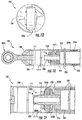
- FIGS. 1E and 1F are sectional views of system 100 , device 200 , and/or portions thereof.
- a structural component 101 includes a primary tube (e.g., a shaft or a strut) having a hollow body 104 with at least one end 102A including an end fitting or connection member.
- Body 104 is connected to an end fitting or connection member via an adapter body or plug component 106 .
- Component 106 may comprise a threaded aperture to which a threaded end fitting (e.g., a threaded eyebolt, a threaded pigtail hook, etc.) may threadingly attach and/or engage.
- Component 106 may also optionally include an outer diameter that is threaded.
- component 106 may threadingly attach and/or engage with a threaded inner wall of body 104 for securing body 104 to end fitting.
- component 106 may be press fit, welded, soldered, or otherwise attached to body 104 .
- Body 104 is supported as a beam between opposing ends (e.g., 102A, 102B ), which are affixed or may be affixed to other structures (not shown) via end fittings.
- damping may be accomplished via flexing (e.g., moving, rubbing, or snubbing) of first damping element 208A against at least one inner wall 104A of body 104 and/or of first damping element 208A between tube member 202 and body 104 .
- the flexing of damping element 208A dissipates vibrational energy (e.g., torsional and/or bending) that is applied or transferred thereto from body 104 .
- damping element 208A includes a viscoelastic material such as an elastomer.
- damping elements 208A is optional and/or dependent upon the amount of damping required, the type of damping required, and/or the damping environment.
- One option for damping element 208A includes providing elastomeric damping elements 208A and 208B.
- the damping loss factor for elastomeric material is between about 0.2 and about 1.2 with the increased loss factor providing increased damping.
- First and second damping elements 208A and 208B ( FIG. 1B ) can attach and/or connect to tube member 202 via the threading of adapter 206 into an end fitting or end plug 214 of tube member 202 .
- End plug 214 may include a body comprising metal, a metal alloy, or any other material (e.g., plastic, polymeric, composite, etc.) depending upon the damping environment and/or system.
- first and second damping elements 208A and 208B may include a metallic mesh type of damping element.
- Providing a metallic mesh type of damping element improves the performance of the damping element at increased temperatures and/or improve the damping element's resistance to fluid and/or a fluid environment.
- first and second damping elements 208A and 208B may include a friction-damping elements (e.g., see FIG. IF), which can be energized by a biasing member, such as a spring element 226A , 226B , to provide a frictional damping force at the end of the internal damper tube member 202 .
- a friction spring element static friction force can prevent sliding.
- damping device 200 can slide and create a friction damping force for dissipating vibratory energy in the form of heat. This provides damping to the primary body 104 and reduces resonant amplitudes.
- Selection of a frictional material and/or a clamping force may be made to provide damping at the appropriate vibratory input levels for installation within a specific type of structural component 101 , for example, a specific component that is subject to expected (e.g., estimated, calculated) vibration levels.
- first and second damping elements 208A and 208B may include a viscous type of damper element that utilizes a viscous fluid in shear to generate a damping force.
- the selection of the damping element type and/or material may be determined by the environment (temperature, fluid exposure, etc.), the amount of damping required, the input vibration levels (high levels can generate high heat output in the damper), assembly or manufacturing considerations, weight concerns, or the like.
- damper device 200 includes a friction damper having a disc member or insert element 220 disposed between one or more friction elements 222A and 222B .
- Insert element 220 may be provided against an inner diameter of body 104 .
- Insert element 220 may be taper locked against body 104 , or affixed via adhesive, brazing, welding, soldering, an interference fit, a press-fit, or the like.
- friction elements 222A and 222B react to motion transferred thereto via the internal damping tube end fitting (e.g., adapter 206 ), and are free to translate along a longitudinal tube axis.
- One or more spring elements 226A and 226B are configured to clamp friction elements 222A and 222B to insert element 220 to generate a frictional force for damping vibration and reducing the amplitude of flexural and/or torsional beaming.
- FIGS. 1A to IF illustrate exemplary embodiments of a lightweight damping device that is targeted at reducing the resonant amplitude of the first several beaming modes and/or torsional modes of vibration for a hollow structural component 101 or power transmission shaft.
- the damper consists of stiff concentric tube (e.g., 202 ) with one or more damping elements (e.g., viscoelastic, mesh, frictional, etc.) provided at each end (e.g., a first end and a second end of the tube member 202 ).
- the device may be inserted within a primary shaft (e.g., 104 ) and attached thereto, in some aspects, via an adhesive or retention ring 204 ( FIG. 1B ).
- the viscoelastic elements can flex and dissipate vibrational energy. This effectively reduces the resonant amplitude of vibration within the structural component 101 .
- the length of damper device 200 is some fraction of the original strut length, for example, and can range from between about 20% to about 70% of the original strut length.
- FIGS. 1A to IF are for illustrative purposes only and that various structures, components, their locations, and/or their functions described above in relation to these figures may be changed, altered, added, or removed. For example, some structures and/or functions (e.g., damper elements, biasing members, etc.) may be separated into multiple entities, combined into a single entity, or utilized in different quantities and/or locations, where desired.
- damper elements e.g., damper elements, biasing members, etc.
- FIGS. 2A to 2C are additional views of portions of an exemplary damping device 200 .
- FIG. 2A is a perspective view of adapter 206 .
- Adapter 206 is configured to affix a damping element (e.g., 208A or 208B ) onto opposing end portions of internal damping tube (e.g., tube member 202 ).
- adapter 206 comprises an end fitting or connection member having a first end 206A , a second end 206B , and a threaded outer body 206C .
- a damping device e.g., a viscoelastic material, a metallic mesh, a frictional damping element, a viscous fluid, etc.
- a damping device abuts retaining portion R and another retaining member (e.g., 210 , FIG. IE).
- Retaining member e.g., 210 , FIG. IE
- Retaining portion R can comprise a shelf, a ledge, a wall, a flange, or the like adapted to prevent damping device 200 from becoming displaced within the primary tube body (e.g., 104 , FIG. 1A ).
- Second end 206B is configured to threadingly engaged a portion of tube member 202 (FIG. IE) for attaching damping elements 208A (FIG. IE) to the stiff tube damping device 200 (FIG. IE).
- FIGS. 2B and 2C illustrate an embodiment of damping elements 208A and 208B (referred to in FIG. 2C as " 208A/B ”) disposed in a damping device.
- damping element 208A/B includes a viscoelastic body having an aperture A that is disposed proximate a center of the damping element body.
- Damping elements 208A and 208B can comprise an outer diameter D 1 that is approximately equal to or slightly less than an inner diameter of a structural component (e.g., 101 ).
- Damping elements 208A and 208B can comprise an inner diameter D 2 that is approximately equal to an end fitting or adapter member (e.g., 206 ) that secures damping elements 208A and 208B to damping device 200 .
- damping elements 208A and 208B comprises a silicone body having a machined aperture A .
- Damping elements 208A and 208B can be disposed on opposing ends of a damping device (e.g., 200 , FIG. 1B ) and flex, thereby dissipating vibration energy and/or resonance of the structural component 101 to which it is inserted.
- FIGS. 2A to 2C are for illustrative purposes only and that various dimensions, sizes, shapes, etc., described above in relation to these figures may be changed, altered, added, or removed, where desired.
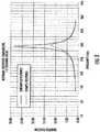
- FIG. 3 is an exemplary graphical illustration comparing damped and un-damped beaming responses according to an embodiment of the presently disclosed subject matter.
- FIG. 3 is a graphical illustration of the reduction in frequency of a beam deflection with and without damping.
- Damping may be provided via a damping system (e.g., 100 , FIG. 1A ) or a damping device (e.g., 200 , FIG. 1B ) disposed inside of a hollow structural component 101. Damping systems and devices stiffen the structural component 101 as well as damp vibration via damping elements without adding significant weight.
- damping devices provided about 28% reduction in the resonant transmissibility for the first bending mode.
- the damping elements described herein are configured to reduce the amplitude of at least the first bending mode of the structural component 101.
- damping devices and systems herein add only a minimal amount of weight to the structural component 101 .
- damping devices and/or systems described herein may add about 14% or less to the original strut (e.g., 101 ) weight.
- the thickness of many shafts, struts, or beams, which are designed according to fatigue strength through resonance may be reduced when vibrations are effectively damped as described herein.
- devices, systems, and methods herein may also allow a strut having a reduced thickness and/or diameter. That is, structural components 101 herein, including the damper element, may weight less than available thicker struts that are designed for increased fatigue strength.
- FIG. 3 illustrates, a reduction in amplitude of the frequency of a first beaming mode is provided by damping systems and/or devices described herein.
- FIG. 3 illustrates the reduction in amplitude for a standard beam with a slenderness ratio of about 18.
- damping devices and/or systems can achieve an about 60% reduction in the amplitude of resonant frequency for the first beaming mode.
- FIG. 4 is a graphical illustration of the primary beaming mode-shapes for a simply supported structural component 101 .
- FIG. 4 graphically illustrates the type of mode shapes that can be targeted for reduction via damping devices and systems described herein.
- the x-axis is the primary shaft overall length (e.g., the length of 101 , FIG. 1A ), and the y-axis is the normalized deflected mode-shape with respect to the shaft.
- FIG. 4 illustrates the first three primary beaming mode-shapes for a simply supported shaft or strut.
- Mode 1 is the mode-shape at its first natural frequency
- Mode 2 at its second natural frequency
- Mode 3 at its third natural frequency.
- Series 4 represents an exemplary length of an internal damping element (e.g., tube member 202 ).
- an internal damping element e.g., tube member 202 .
- a small and lightweight internal damping element can minimize the amplitude of the first three bending modes, in addition to torsional modes by at least about 20% to about 60% or more as noted above.
- FIGS. 3 and 4 are exemplary, and for illustrative purposes only.
Landscapes
- Engineering & Computer Science (AREA)
- General Engineering & Computer Science (AREA)
- Mechanical Engineering (AREA)
- Physics & Mathematics (AREA)
- Acoustics & Sound (AREA)
- Aviation & Aerospace Engineering (AREA)
- Vibration Dampers (AREA)
- Vibration Prevention Devices (AREA)
Abstract
Description
- The present application claims priority to
U.S. Provisional Patent Application Serial No. 62/159,709, filed on May 11, 2015 - The subject matter herein relates generally to devices, systems, and methods for damping vibration. The subject matter herein more particularly relates to devices, systems, and methods for damping the resonant amplitude of beaming and/or torsional modes of vibration associated with a structural component.
- Structural components, including shafts, struts, and beams, are used in a variety of different applications, for example, in frames or mounts for supporting, equipment or machinery. Individual shafts and/or struts are typically hollow, which allows manufacturers and/or operators to benefit from reductions in cost and/or weight, for example, especially in regards to vehicle (e.g., aircraft, automobile, etc.) systems. Rotating components within the supported machinery (e.g., engines, motors, rotors, propellers, or the like) can impart vibration to the hollow shafts and struts supporting the equipment. In some aspects, this vibration can excite flexural and torsional beaming modes of vibration imparted to individual struts within a frame or mount. In other applications, hollow rotating shafts, supported within bearings, are used for power-transmission in various types of machinery. In these applications, operational angular velocities near or through the shaft's critical speed range can induce resonant vibration throughout the shaft and equipment.
- Conventional methods of reducing vibration within a structural component or power transmission shaft include either designing a component that will have a suitable margin or thickness between the rotating structure and the individual structural component, or providing a tuned mass for altering the tuning of the structural component. Conventional methods are problematic, however, as adding margins and/or tuned masses will increase the weight of the structural component, which is undesirable.
- Accordingly, a need exists for improved damping devices, systems, and methods for decreasing vibration within a structural component or power-transmission shaft, and reducing the amplitude of flexural and/or torsional beaming modes of vibration that are acting on the structural component.
- In accordance with this disclosure, damping devices, systems, and methods for damping resonant vibrations of a hollow strut, shaft, or tube are provided. An exemplary damping device includes a tube member comprising a first end and a second end. A first damping element is disposed on the first end of the tube member and a second damping element disposed at the second end of the tube member. The first and second damping elements are configured to flex against a structural component for dissipating energy from the structural component and for reducing the bending of the structural component due to modal characteristics induced by vibration.
- In some embodiments, damping devices herein are configured to physically contact the structural component in three discrete locations, or less. Damping devices herein are configured to physically contact the structural component in a location proximate a center of a longitudinal axis of the structural component. Damping devices herein comprise a length that is between about 10% and about 80% of the length of the structural component. Damping devices herein are attached to a structural component via a retention ring, a clamp, adhesive, brazing, or welding.
- An exemplary damping system comprises a hollow structural component and a damping device disposed inside the hollow structural component. The damping device comprises a tube member that is concentric with the structural component or power transmission shaft and at least one damping element attached to a portion of the tube member. The damping element is disposed between portions of an inner wall of the structural component and the tube member. The damping element is configured to dissipate vibration and reduce bending of the structural component due to modal characteristics excited by vibration of the supported equipment or rotating shaft. The damping device physically contacts the inner wall of the structural component in three discrete contact points or less.
- An exemplary method of damping vibration includes providing a tube member comprising a first end and a second end, attaching a first damping element to the first end of the tube member, and attaching a second damping element to the second end of the tube member. The method further includes flexing the first and second damping elements against a structural component or power-transmission shaft for dissipating energy from the component and for reducing the bending of the component due to modal characteristics excited by vibration.
- In some embodiments, damping devices herein include damping elements comprising a viscoelastic material, such as silicone. In some embodiments, damping elements include a spring element that is configured to clamp a friction element to an insert element to generate a frictional force to damp vibration. In some embodiments, damping elements include a metallic mesh for higher temperature resistance. In some embodiments, the damping elements are each configured to flex against an inner wall of the structural component.
- In one aspect, a damping device is provided. The damping device comprises a structural component, a tube member, a first damping element, and a second damping element. The tube member is disposed inside of the structural component, the tube member having a first end and a second end. The first damping element is disposed on the first end of the tube member. The second damping element is disposed on the second end of the tube member. Wherein the first damping element and the second damping element are configured to flex against the structural component for dissipating energy from the structural component and for reducing the bending of the structural component due to modal characteristics induced by vibration. In one embodiment, the damping device physically contacts the structural component in three discrete locations (I, II, III) or less. In one embodiment, the damping device physically contacts the structural component in a location (II) proximate a center (CL) of a longitudinal axis of the structural component. In one embodiment, the tube member comprises a length that is between about 10% and about 80% of the length of the structural component. In one embodiment, at least one of the first and second damping elements comprises silicone. In one embodiment, at least one of the first and second damping elements comprises a spring element that is configured to clamp a friction element to an insert element to generate a frictional force to damp vibration. In one embodiment, at least one of the first and second damping elements comprise a metallic mesh for higher temperature resistance. In one embodiment, the first damping element and the second damping element are configured to flex against an inner wall of the structural component. In one embodiment, the tube member is attached to the structural component via a retention ring, a clamp, adhesive, brazing, or welding.
- In another aspect, a damping system is provided. The damping system comprises a structural component, and a damping device. The structural component comprising at least one inner wall, the structural component being hollow. The damping device is disposed within the structural component. The damping device further comprises a tube member and at least one damping element. The tube member is concentric with the structural component. The at least one damping element is attached to a portion of the tube member, wherein the damping element is disposed between portions of the inner wall of the structural component and the tube member. Wherein the damping element is configured to dissipate vibration and reduce bending of the structural component due to modal characteristics induced by vibration of the structural component. In one embodiment, the system comprises having the damping device physically contacts the inner wall of the structural component in at least two or more contact points (I, II). In one embodiment, the system comprises having at least a one contact point (II) proximate a center (CL) of a longitudinal axis of the structural component. In one embodiment, the system further comprises a first and second damping elements disposed on opposing ends of the tube member. In one embodiment, the tube member comprises a length that is between about 10% and about 80% of the length of the structural component. In one embodiment, the at least one damping element comprises silicone. In one embodiment, the at least one damping element comprises a spring element that is configured to clamp a friction element to an insert element for generating a frictional force to damp vibration. In one embodiment, the at least one damping element comprises a metallic mesh. In one embodiment, the at least one damping element is configured to reduce a resonant amplitude of at least a first bending mode of the structural component.
- In yet another aspect, a method of vibration damping is provided. The method includes the steps of:
- A. providing a structural component (101);
- B. providing a tube member (202) within the structural component, the tube member having a first end (E1) and a second end (E2);
- C. attaching a first damping element (208A) to the first end of the tube member and attaching a second damping element (208B) to the second end of the tube member; and
- D. flexing the first and second damping elements against the structural component for dissipating energy from the structural component and for reducing the bending of the structural component due to modal characteristics excited by vibration
- In one embodiment, the method further comprises positioning the damping device inside of the structural component so that the damping device physically contacts the structural component at least three discrete locations (I, II, III). In one embodiment, the method further comprises positioning the damping device inside of the structural component so that the damping device physically contacts the structural component in a location (II) that is proximate a center (CL) of a longitudinal axis of the structural component.
- Damping devices, systems, and methods herein reduce the resonant amplitude of the first several beaming modes and/or torsional modes of a hollow shaft or strut. Numerous objects and advantages of the inventive subject matter will become apparent as the following detailed description of the preferred embodiments is read in conjunction with the drawings, which illustrate such embodiments.
-
-
FIGS. 1A-1D are perspective side, sectional, and end views of a damping device and system according to an embodiment of the presently disclosed subject matter. -
FIGS. 1E-1F are sectional views of the damping device and system according to an embodiment of the presently disclosed subject matter. -
FIGS. 2A-2C are portions of a damping device according to an embodiment of the presently disclosed subject matter. -
FIG. 3 is a graphical illustration comparing damped and un-damped beaming responses according to an embodiment of the presently disclosed subject matter. -
FIG. 4 is a graphical illustration of the primary beaming mode-shapes for a simply supported structural component. - Figures (also "
FIGS.") 1A to 4 illustrate various views, embodiments, and/or aspects associated with vibration damping devices, systems, and related methods by which the life of structural components associated with rotating machinery or equipment may be extended. In some embodiments, devices, systems, and methods herein dissipate vibrational energy via the addition of stiffness and/or damping to a structural component, such as a hollow strut or shaft. Devices, systems, and methods herein are configured to reduce the resonant transmissibility associated with torsional modes and/or one or more primary bending modes of a structural component (e.g., a fixed shaft, strut, or beam). In some embodiments, the thickness of many shafts, struts, or beams, which were originally designed according to fatigue strength through resonance, may be reduced when vibrations are effectively damped. Thus, devices, systems, and methods herein provide a strut-and-damper assembly, which may advantageously be lighter-weight than the original strut. - Devices, systems, and methods set forth herein may be used in many different applications, not limited to use within structural components and/or structural component systems, such as, for example, rotating shafts (e.g., operating near a critical speed or accelerating through a critical speed), airframe struts, auxiliary power unit supports, support frame components, engine attachment supports and frame components, attach frame components, engine mount components, drive shafts (e.g., for vehicles not limited to aircraft and/or automobiles), high-speed internal shafts within engines, power transmission shafts in high-speed rotating equipment, vehicle systems, engine systems, or the like.
- Damper devices, systems, and methods herein may comprise internal damping devices, suited for damping vibration and/or resonant amplitude of various structural components such as shafts, struts, frame members, and/or beams. In some embodiments, devices, systems, and methods herein can be used address the torsional mode (twist) of the structural component along with the primary bending or beaming modes.
- Referring to
FIGS. 1A-4 , several non-limiting, exemplary embodiments of damping devices, systems, and methods are illustrated. As each of the figures is exemplary, some elements and/or the functionality thereof may be combined, separated, integrated, and/or modified while remaining within the scope of the claims. - Referring to
FIGS. 1A-1C , a damping system, generally designated 100, is illustrated. In some embodiments, dampingsystem 100 includes at least onestructural component 101 and a damping device, generally designated 200. As illustrated,structural component 101 includes a strut, shaft, a beam, or the like. Dampingdevice 200 may include an internal damping device, which is configured to attach or connect to the structural component and in some embodiments, is inserted therein and/or integrated therewith. Dampingdevice 200 includes a first end E1 and a second end E2 opposing the first end. -
FIG. 1A is a perspective view of astructural component 101, such as a beam, a strut, a bar, or a shaft, having acomponent body 104 disposed between afirst end 102A and asecond end 102B.Structural component 101 may be used alone and/or in combination with one or more additionalstructural components 101 to form a frame or mounting structure for supporting and/or mounting portions of a machine with vibration-producing sources (not shown, e.g., an engine, rotor, propeller, drive shaft, rotating shaft, etc.). First and second ends 102A and 102B may include end fittings that are fixedly attached or connected to one or more additional structures (not shown) for supportingbody 104 therebetween. In some embodiments, each end (e.g., 102A, 102B) include eye-bolts, fasteners, pins, clips, hooks, screws, twist-lock fittings, snap on fittings, or any other type of fittings or fastening structures. - In some embodiments, first and second ends 102A and 102B may independently connect and/or affix to a fixed support structure for an engine mount, a fixed machine component, a fixed housing (e.g., an engine housing), etc. In some exemplary embodiments,
body 104 exhibits or experiences one or more resonant beaming modes (e.g., bending and/or torsional modes) when vibrations are transferred thereto from the supported equipment (not shown). Damping devices, systems, and methods herein are configured to reduce the resonant transmissibility associated with one or more primary beaming modes and/or torsional modes acting on astructural component body 104. In some embodiments,body 104 includes a primary shaft, strut, beam, bar, or tube that is configured to receive (e.g., internally) a secondary damping tube in the form of a damping device 200 (FIG. 1B ).Body 104 may be formed of any material including but not limited to metal, a metal alloy, steel, aluminum (Al), plastic, any rigid material, any flexible material, any composite material, or the like. -
FIG. 1B is a sectional view ofsystem 100 taken longitudinally between first and second ends 102A and 102B ofFIG. 1A . AsFIG. 1B illustrates, thestructural component 101 may include ahollow body 104. As illustrated, a dampingdevice 200 is positioned or otherwise disposed within a portion ofbody 104, for example, between one or moreinner walls 104A ofstructural component 101 and/orbody 104. Dampingdevice 200 is configured to physically contact body 104 (e.g.,inner walls 104A of body 104) in at least two or more locations. AsFIG. 1B illustrates,device 200 may contactbody 104 in at least three locations, generally designated I, II, and III. The number of contact points or contact locations (e.g., I, II, III) betweendevice 200 andbody 104 ofstructural component 101 depends upon the length and/or diameter ofbody 104, and is not limited to any specific number of contact points or contact locations. - In some embodiments,
device 200 comprises a tubular (cylindrical) shaped body ortube member 202 that is disposed withinbody 104 of a hollow shaft or strut. In some embodiments,tube member 202 andbody 104 are concentric structures having a same centerline, center plane, center point, or center axis (any of a center x, y, or z-axis). In some aspects,body 104 is referred to as a "primary" tube andtube member 202 is referred to as a "secondary" tube within dampingsystem 100.Tube member 202 may include a stiff and/or rigid structure having an outer diameter that is smaller than an inner diameter ofbody 104, and can contact or connect tobody 104 via a retaining structure or retaining ring, generally designated 204. - In some embodiments, retaining
ring 204 includes one or more annular rings (e.g., 204A, 204B,FIG. 1C ) disposed about an outermost diameter oftube member 202. Retainingring 204 can comprise one or more components that are configured to clamp a portion ofdevice 200 tobody 104 and/orfrictionally retain device 200 againstinner walls 104A (FIG. 1C ) ofbody 104. Retainingring 204 may comprise a single retaining structure (e.g., ring) or a plurality of retaining structures (e.g., rings). - In some
embodiments retaining ring 204 is disposed proximate a centerline or a central axis oftube member 202 andbody 104, for example, along a centerline that bisects each tube (e.g., 202 and 104) along the respective longitudinal length into two substantially equal portions having a substantially same dimension. Retainingring 204 may include a single annular member or multiple annular members configured to retaindevice 200 against one or moreinner walls 104A ofbody 104, the members may overlap and/or be spaced apart from each other during retention ofdevice 200 againstinner wall 104A, potentially incorporating self-locking taper angles. - In some embodiments, retaining
ring 204 is exemplary and optional, as an adhesive and/or interference fit component, press fit component, etc. may be provided betweentube member 202 andbody 104 to connecttube member 202 tobody 104. For example,tube member 202 ofdevice 200 may be secured tobody 104 via adhesive, one or more mechanical fasteners (e.g., pins, hooks, screws, etc.), one or more frictional fasteners, one or more press fit components, soldering, brazing, welding, or the like. In some embodiments, retainingring 204 comprises at least one tapered clamp ring. Where a metaldamper tube member 202 is used, brazing, soldering, and/or welding may be used to attach the damper tube (e.g., tube member 202) to the primary tube (e.g., body 104). - As
FIGS. 1B and 1C illustrate, dampingdevice 200 is configured to contactbody 104 at a first location I and a third location III via one or more damping devices or elements, in some embodiments, at least a first dampingelement 208A and a second dampingelement 208B. Each damping element (e.g., 208A and 208B) can comprise any suitable material and/or structure depending upon the amount of damping required and/or the damping environment. For example and in some embodiments, each damping element (e.g., 208A and 208B) may include a viscoelastic component, a metal component, a metal alloy component, a frictional spring damping component, an elastomer component, a plastic component, a wire mesh component or material, a friction-inducing element or component or material, a single discrete damping component, a multi-layered component, or the like. First and second dampingelements element 208A can comprise a different size, shape, structure, and/or material than the other, second dampingelement 208B. - In some embodiments, each damping element (e.g., 208A and 208B) is configured to dissipate energy (e.g., mechanical energy, vibrational energy, or the like) via flexing in response to vibrations and/or bending imparted to the
body 104. In other embodiments, each damping element (e.g., 208A and 208B) is configured to dissipate vibrational energy upon the generation of friction or heat. Any size, shape, quantity, and/or type of damping element(s) can be provided. In this configuration, provision of discrete first and second dampingelements tube member 202 and/orbody 104 can advantageously allow such elements or components to be readily installed and/or replaced as needed, while still providing effective damping when in an installed state. However, more than two, or less than two damping elements may also be provided. - In some embodiments, damping
device 200 is configured to contactbody 104 at a second, centralized location II via retainingring 104 or other retaining structure and/or retaining material. In some embodiments, dampingdevice 200only contacts body 104 at three locations. In other embodiments, dampingdevice 200contacts body 104 at more than three locations (e.g., where alonger body 104 is provided) or at less than three locations (e.g., where ashorter body 104 is provided). The length of dampingdevice 200 as compared to the length ofbody 104 may be optimized or improved as desired, for example, based upon factors including the amount of damping desired, the type of damping desired (e.g., resonant, torsional), the beaming mode, and/or the damping environment (e.g., thermal environment, chemical environment, etc.). - In some embodiments,
tube member 202 is a stiff and/or substantially rigid body of material comprising a metal, a metal alloy, steel, Al, plastic, a composite material, or any other stiff, lightweight material.Tube member 202 may also be hollow for facilitating weight reduction ofsystem 100. Dampingdevice 200 may be configured to dissipate energy via the addition of both stiffness and damping, which can collectively and effectively reduce the resonant amplitude at whichbody 104 is vibrating. - In some embodiments, a length of
device 200 ranges from about 10% to about 80% of the length of the overall, original body 104 (e.g., not including ends 102A and 102B). The length ofdevice 200 andrespective tube member 202 can be validated, optimized, and/or set to any value, where desired. In some embodiments,body 104 is about 24 inches (about 61 centimeters) long andtube member 202 can range in length from about 4.8 inches to about 20 inches (about 12.2 centimeters to about 51 centimeters). Any length ofbody 104 and/ortube member 202 can be provided. Similarly, any ratio between the length ofbody 104 andtube member 202 can be provided. In some aspects,body 104 andtube member 202 comprise concentric and cylindrical annular-shaped shells, whereinbody 104 fully encases and/or surroundstube member 202. A non-limiting ratio between a length (LB) ofbody 104 and a length (LT) oftube member 202 may include a ratio (LB/LT) of about 0.5 or more, about 1.0 or more, about 1.3 or more, about 2.0 or more, about 3.0 or more, about 4.0 or more, about 5.0 or more, or the like. - Referring to
FIG. 1C and in some embodiments, dampingelement 208A is illustrated as being secured totube member 202 via an end fitting oradapter 206.Adapter 206 may include a body of metal or a metal alloy configured to isolate a respective damping element (e.g., 208A and 208B) and connect the damping element to outermost, opposing ends oftube member 202.FIG. 1C is an enhanced (closer) view of one-half ofsystem 100 anddevice 200 as shown inFIG. 1B , with the opposing side (not shown) being a mirror image of that shown. A retainingmember 210 and a securingelement 212 can further isolate each damping element (e.g., 208A and 208B) to an end ofdevice 200, and secure damping element toadapter 206. In some aspects, securingelement 212 includes a hexagonal nut configured to threadingly engage a body ofadapter 206 for securing first dampingelement 208A thereto. - As
FIG. 1C further illustrates, retainingring 204 includes one or more (e.g., a plurality of) annular rings disposed in a stack and/or a layered or sandwich structure for retainingdevice 200 within body 104 (e.g., within aninner wall 104A of a strut, shaft, beam, or structural component 101). Retainingring 204 may include an outertapered ring member 204A disposed over and/or about one or more innertapered ring members 204B.Outer ring member 204A andinner ring members 204B include a tapered cross-section, and each ring member is configured to clamp together about or against an outer diameter oftube member 202 for securingtube member 202 to aninner wall 104A ofbody 104. Retainingring 204 and/or portions thereof (e.g., 204A, 204B, etc.) can comprise any material including but not limited to a metal, a metal alloy, steel, Al, plastic, a polymer, or the like. - In some embodiments, first and second damping
elements device 200. Dampingelements elements elements structural component 101 orbody 104, for example, a vibrating shaft or strut. A method of damping vibration includes providing a hollow structural component (e.g., a shaft, strut, or beam) 101 and inserting (positioning) a dampingdevice 200 within thebody 104 of the hollowstructural component 101. Dampingdevice 200 may include one or more discrete damping elements (e.g. 208A and 208B) optionally disposed on opposing ends of the dampingdevice 200. - First and
second elements elements body 104 for dissipating vibrational energy to reduce resonance of thestructural component 101 orbody 104 asbody 104 exhibits one or more beaming modes of vibration. -
FIG. 1D is an end view ofsystem 100 as shown and described inFIG. 1A . Eachend 102A and/or 102B can affix to another structure such thatbody 104 may be simply supported therebetween. Whenbody 104 rotates and/or a rotating component imparts vibration tobody 104,body 104 can resonate and exhibit a torsional mode and/or one or more primary beaming modes of vibration. Dampingdevice 200 is configured to damp the amplitude of the resonant vibration without introduction of a tuning mass and/or without having to increase a distance, space, or margin betweenbody 104 and the source of the vibration. -
FIGS. 1E and 1F are sectional views ofsystem 100,device 200, and/or portions thereof. Astructural component 101 includes a primary tube (e.g., a shaft or a strut) having ahollow body 104 with at least oneend 102A including an end fitting or connection member.Body 104 is connected to an end fitting or connection member via an adapter body or plugcomponent 106.Component 106 may comprise a threaded aperture to which a threaded end fitting (e.g., a threaded eyebolt, a threaded pigtail hook, etc.) may threadingly attach and/or engage.Component 106 may also optionally include an outer diameter that is threaded. The outer diameter ofcomponent 106 may threadingly attach and/or engage with a threaded inner wall ofbody 104 for securingbody 104 to end fitting. In other embodiments,component 106 may be press fit, welded, soldered, or otherwise attached tobody 104.Body 104 is supported as a beam between opposing ends (e.g., 102A, 102B), which are affixed or may be affixed to other structures (not shown) via end fittings. - In FIG. IE, damping may be accomplished via flexing (e.g., moving, rubbing, or snubbing) of first damping
element 208A against at least oneinner wall 104A ofbody 104 and/or of first dampingelement 208A betweentube member 202 andbody 104. The flexing of dampingelement 208A dissipates vibrational energy (e.g., torsional and/or bending) that is applied or transferred thereto frombody 104. In some embodiments, dampingelement 208A includes a viscoelastic material such as an elastomer. However, the material chosen for dampingelements 208A is optional and/or dependent upon the amount of damping required, the type of damping required, and/or the damping environment. One option for dampingelement 208A includes providing elastomeric dampingelements elements FIG. 1B ) can attach and/or connect totube member 202 via the threading ofadapter 206 into an end fitting orend plug 214 oftube member 202.End plug 214 may include a body comprising metal, a metal alloy, or any other material (e.g., plastic, polymeric, composite, etc.) depending upon the damping environment and/or system. - In other embodiments, at least one of first and second damping
elements FIG. 1B ) may include a metallic mesh type of damping element. Providing a metallic mesh type of damping element improves the performance of the damping element at increased temperatures and/or improve the damping element's resistance to fluid and/or a fluid environment. - In some embodiments, at least one of first and second damping
elements spring element damper tube member 202. Under low vibratory loads, a friction spring element static friction force can prevent sliding. When vibratory levels exceed a level needed to generate force above the static friction force, then dampingdevice 200 can slide and create a friction damping force for dissipating vibratory energy in the form of heat. This provides damping to theprimary body 104 and reduces resonant amplitudes. Selection of a frictional material and/or a clamping force may be made to provide damping at the appropriate vibratory input levels for installation within a specific type ofstructural component 101, for example, a specific component that is subject to expected (e.g., estimated, calculated) vibration levels. - In yet further embodiments, at least one of first and second damping
elements - Referring to FIG. IF and in some embodiments, damping is accomplished via a friction damper arrangement. In some embodiments,
damper device 200 includes a friction damper having a disc member or insertelement 220 disposed between one ormore friction elements Insert element 220 may be provided against an inner diameter ofbody 104.Insert element 220 may be taper locked againstbody 104, or affixed via adhesive, brazing, welding, soldering, an interference fit, a press-fit, or the like. In some embodiments,friction elements more spring elements friction elements element 220 to generate a frictional force for damping vibration and reducing the amplitude of flexural and/or torsional beaming. -
FIGS. 1A to IF illustrate exemplary embodiments of a lightweight damping device that is targeted at reducing the resonant amplitude of the first several beaming modes and/or torsional modes of vibration for a hollowstructural component 101 or power transmission shaft. The damper consists of stiff concentric tube (e.g., 202) with one or more damping elements (e.g., viscoelastic, mesh, frictional, etc.) provided at each end (e.g., a first end and a second end of the tube member 202). The device may be inserted within a primary shaft (e.g., 104) and attached thereto, in some aspects, via an adhesive or retention ring 204 (FIG. 1B ). In some embodiments, when the primary shaft (e.g., body 104) undergoes bending due to modal characteristics, the viscoelastic elements can flex and dissipate vibrational energy. This effectively reduces the resonant amplitude of vibration within thestructural component 101. The length ofdamper device 200 is some fraction of the original strut length, for example, and can range from between about 20% to about 70% of the original strut length. - It will be appreciated that
FIGS. 1A to IF are for illustrative purposes only and that various structures, components, their locations, and/or their functions described above in relation to these figures may be changed, altered, added, or removed. For example, some structures and/or functions (e.g., damper elements, biasing members, etc.) may be separated into multiple entities, combined into a single entity, or utilized in different quantities and/or locations, where desired. -
FIGS. 2A to 2C are additional views of portions of an exemplary dampingdevice 200.FIG. 2A is a perspective view ofadapter 206.Adapter 206 is configured to affix a damping element (e.g., 208A or 208B) onto opposing end portions of internal damping tube (e.g., tube member 202). As illustrated,adapter 206 comprises an end fitting or connection member having afirst end 206A, asecond end 206B, and a threadedouter body 206C. A damping device (e.g., a viscoelastic material, a metallic mesh, a frictional damping element, a viscous fluid, etc.) can be secured between a retainer and/or retaining portion R ofadapter 206 and another retaining member (e.g., 210, FIG. IE). In some embodiments, a damping device abuts retaining portion R and another retaining member (e.g., 210, FIG. IE). Retaining member (e.g., 210, FIG. IE) may be disposed over and/or threadingly engagefirst end 206A ofadapter 206. Retaining portion R can comprise a shelf, a ledge, a wall, a flange, or the like adapted to prevent dampingdevice 200 from becoming displaced within the primary tube body (e.g., 104,FIG. 1A ).Second end 206B is configured to threadingly engaged a portion of tube member 202 (FIG. IE) for attaching dampingelements 208A (FIG. IE) to the stiff tube damping device 200 (FIG. IE). -
FIGS. 2B and 2C illustrate an embodiment of dampingelements FIG. 2C as "208A/B") disposed in a damping device. In this embodiment, dampingelement 208A/B includes a viscoelastic body having an aperture A that is disposed proximate a center of the damping element body. Dampingelements elements elements device 200. In some aspects, dampingelements A . Damping elements FIG. 1B ) and flex, thereby dissipating vibration energy and/or resonance of thestructural component 101 to which it is inserted. - It will be appreciated that
FIGS. 2A to 2C are for illustrative purposes only and that various dimensions, sizes, shapes, etc., described above in relation to these figures may be changed, altered, added, or removed, where desired. -
FIG. 3 is an exemplary graphical illustration comparing damped and un-damped beaming responses according to an embodiment of the presently disclosed subject matter.FIG. 3 is a graphical illustration of the reduction in frequency of a beam deflection with and without damping. Damping may be provided via a damping system (e.g., 100,FIG. 1A ) or a damping device (e.g., 200,FIG. 1B ) disposed inside of a hollowstructural component 101. Damping systems and devices stiffen thestructural component 101 as well as damp vibration via damping elements without adding significant weight. In some embodiments, damping devices provided about 28% reduction in the resonant transmissibility for the first bending mode. In some aspects, the damping elements described herein are configured to reduce the amplitude of at least the first bending mode of thestructural component 101. - In some embodiments, damping devices and systems herein add only a minimal amount of weight to the
structural component 101. For example, damping devices and/or systems described herein may add about 14% or less to the original strut (e.g., 101) weight. In some embodiments, the thickness of many shafts, struts, or beams, which are designed according to fatigue strength through resonance, may be reduced when vibrations are effectively damped as described herein. Thus, devices, systems, and methods herein may also allow a strut having a reduced thickness and/or diameter. That is,structural components 101 herein, including the damper element, may weight less than available thicker struts that are designed for increased fatigue strength. - As
FIG. 3 illustrates, a reduction in amplitude of the frequency of a first beaming mode is provided by damping systems and/or devices described herein.FIG. 3 illustrates the reduction in amplitude for a standard beam with a slenderness ratio of about 18. AsFIG. 3 illustrates, damping devices and/or systems can achieve an about 60% reduction in the amplitude of resonant frequency for the first beaming mode. -
FIG. 4 is a graphical illustration of the primary beaming mode-shapes for a simply supportedstructural component 101.FIG. 4 graphically illustrates the type of mode shapes that can be targeted for reduction via damping devices and systems described herein. InFIG. 4 , the x-axis is the primary shaft overall length (e.g., the length of 101,FIG. 1A ), and the y-axis is the normalized deflected mode-shape with respect to the shaft. -
FIG. 4 illustrates the first three primary beaming mode-shapes for a simply supported shaft or strut.Mode 1 is the mode-shape at its first natural frequency,Mode 2 at its second natural frequency, andMode 3 at its third natural frequency. Series 4 represents an exemplary length of an internal damping element (e.g., tube member 202). Thus, a small and lightweight internal damping element can minimize the amplitude of the first three bending modes, in addition to torsional modes by at least about 20% to about 60% or more as noted above. It will be appreciated thatFIGS. 3 and4 are exemplary, and for illustrative purposes only. - Other embodiments of the current subject matter will be apparent to those skilled in the art from a consideration of this specification or practice of the subject matter disclosed herein. Thus, the foregoing specification is considered merely exemplary of the current subject matter with the true scope thereof being defined by the following claims.
Claims (18)
- A damping device (200) comprising:a structural component (101);a tube member (202) disposed inside of the structural component (101), the tube member (202) having a first end (E1) and a second end (E2);a first damping element (208A) disposed on the first end (E1) of the tube member (202);a second damping element (208B) disposed on the second end (E2) of the tube member (202);characterized by the first damping element (208A) and the second damping element (208B) are configured to flex against the structural component (101) for dissipating energy from the structural component (101) and for reducing the bending of the structural component (101) due to modal characteristics induced by vibration; andwherein the damping device (200) physically contacts the structural component (101) in three discrete locations (I, II, III).
- The device of claim 1, wherein the damping device physically contacts the structural component in a location (II) proximate a center (CL) of a longitudinal axis of the structural component.
- The device of claim 1, wherein the tube member comprises a length that is between about 10% and about 80% of the length of the structural component.
- The device of claim 1, wherein at least one of the first and second damping elements comprises silicone.
- The device of claim 1, wherein at least one of the first and second damping elements comprises a spring element (226A) that is configured to clamp a friction element (222A) to an insert element (220) to generate a frictional force to damp vibration.
- The device of claim 1, wherein at least one of the first and second damping elements comprise a metallic mesh for higher temperature resistance.
- The device of claim 1, wherein the first damping element and the second damping element are configured to flex against an inner wall (104A) of the structural component.
- The device of claim 1, wherein the tube member is attached to the structural component via a retention ring (204), a clamp, adhesive, brazing, or welding.
- A damping system (100) comprising:a structural component (101) comprising at least one inner wall (104A), the structural component (101) being hollow; anda damping device (200) disposed within the structural component (101), wherein the damping device (200) comprises:a tube member (202) that is concentric with the structural component (101); andat least one damping element (208A) attached to a portion of the tube member (202), wherein the damping element (200) is disposed between portions of the at least one inner wall (104) of the structural component (101) and the tube member (202);characterized by the damping element (208A) is configured to dissipate vibration and reduce bending of the structural component (101) due to modal characteristics induced by vibration of the structural component (101); andwherein the damping device (200) physically contacts the inner wall (104A) of the structural component (101) in at least three contact points (I, II, III).
- The system of claim 9, wherein at least a one contact point (II) is proximate a center (CL) of a longitudinal axis of the structural component (101).
- The system of claim 10, further comprising first and second damping elements (208A, 208B) disposed on opposing ends (E1, E2) of the tube member (202).
- The system of claim 9, wherein the tube member (202) comprises a length that is between about 10% and about 80% of the length of the structural component (101).
- The system of claim 9, wherein the at least one damping element (208A) comprises silicone.
- The system of claim 9, wherein the at least one damping element (208A) comprises a spring element (226A) that is configured to clamp a friction element (222A) to an insert element (220) for generating a frictional force to damp vibration.
- The system of claim 9, wherein the at least one damping element (208A) comprises a metallic mesh.
- The system of claim 9, wherein the at least one damping element (208A) is configured to reduce a resonant amplitude of at least a first bending mode of the structural component (101).
- A method of vibration damping, the method comprising:providing a structural component (101);providing a tube member (202) within the structural component (101), the tube member (202) having a first end (E1) and a second end (E2);attaching a first damping element (208A) to the first end (E1) of the tube member (202) and attaching a second damping element (208B) to the second end (E2) of the tube member (202);the method characterized by flexing the first and second damping elements (208A, 208B) against the structural component (101) for dissipating energy from the structural component (101) and for reducing the bending of the structural component (101) due to modal characteristics excited by vibration; andpositioning the damping device inside of the structural component so that the damping device physically contacts the structural component at least three discrete locations (I, II, III).
- The method of claim 17, further comprising positioning the damping device (200) inside of the structural component (101) so that the damping device (200) physically contacts the structural component (101) in a location (II) that is proximate a center (CL) of a longitudinal axis of the structural component (101).
Applications Claiming Priority (3)
| Application Number | Priority Date | Filing Date | Title |
|---|---|---|---|
| US201562159709P | 2015-05-11 | 2015-05-11 | |
| PCT/US2016/031756 WO2016183139A1 (en) | 2015-05-11 | 2016-05-11 | Damping devices, systems and methods for hollow shafts, struts, and beams with bending modes |
| EP16725987.8A EP3295052B1 (en) | 2015-05-11 | 2016-05-11 | Damping devices, systems and methods for hollow shafts, struts, and beams with bending modes |
Related Parent Applications (2)
| Application Number | Title | Priority Date | Filing Date |
|---|---|---|---|
| EP16725987.8A Division-Into EP3295052B1 (en) | 2015-05-11 | 2016-05-11 | Damping devices, systems and methods for hollow shafts, struts, and beams with bending modes |
| EP16725987.8A Division EP3295052B1 (en) | 2015-05-11 | 2016-05-11 | Damping devices, systems and methods for hollow shafts, struts, and beams with bending modes |
Publications (2)
| Publication Number | Publication Date |
|---|---|
| EP3418603A1 true EP3418603A1 (en) | 2018-12-26 |
| EP3418603B1 EP3418603B1 (en) | 2025-08-27 |
Family
ID=56087527
Family Applications (2)
| Application Number | Title | Priority Date | Filing Date |
|---|---|---|---|
| EP18184389.7A Active EP3418603B1 (en) | 2015-05-11 | 2016-05-11 | Damping devices, systems and methods for hollow shafts, struts, and beams with bending modes |
| EP16725987.8A Active EP3295052B1 (en) | 2015-05-11 | 2016-05-11 | Damping devices, systems and methods for hollow shafts, struts, and beams with bending modes |
Family Applications After (1)
| Application Number | Title | Priority Date | Filing Date |
|---|---|---|---|
| EP16725987.8A Active EP3295052B1 (en) | 2015-05-11 | 2016-05-11 | Damping devices, systems and methods for hollow shafts, struts, and beams with bending modes |
Country Status (5)
| Country | Link |
|---|---|
| US (1) | US11306794B2 (en) |
| EP (2) | EP3418603B1 (en) |
| CN (1) | CN107580661B (en) |
| CA (1) | CA2984107A1 (en) |
| WO (1) | WO2016183139A1 (en) |
Families Citing this family (4)
| Publication number | Priority date | Publication date | Assignee | Title |
|---|---|---|---|---|
| CN107580661B (en) | 2015-05-11 | 2019-09-06 | 洛德公司 | Damping devices, systems and methods for hollow shafts, struts and beams having bending modes |
| US10479515B2 (en) * | 2016-08-10 | 2019-11-19 | Sikorsky Aircraft Corporation | Dual mode supplemental strut and damper |
| US12162631B2 (en) * | 2020-12-17 | 2024-12-10 | Maxar Space Llc | Passively damped end fittings and brackets |
| CN113982821B (en) * | 2021-10-27 | 2023-07-04 | 大唐桦川风力发电有限公司 | Blade damping device of wind driven generator |
Citations (4)
| Publication number | Priority date | Publication date | Assignee | Title |
|---|---|---|---|---|
| DE2747225A1 (en) * | 1977-10-21 | 1979-04-26 | Porsche Ag | DEVICE FOR REDUCING BENDING VIBRATIONS |
| US5667204A (en) * | 1995-06-26 | 1997-09-16 | Aesop, Inc. | Slit-tube replicated in-place constrained layer damper and method |
| JP2003184940A (en) * | 2001-12-20 | 2003-07-03 | Toyo Tire & Rubber Co Ltd | Liquid filling type vibration damping device |
| JP2004156674A (en) * | 2002-11-05 | 2004-06-03 | Tokai Rubber Ind Ltd | Dynamic damper for hollow rotary shaft |
Family Cites Families (36)
| Publication number | Priority date | Publication date | Assignee | Title |
|---|---|---|---|---|
| US2028930A (en) * | 1934-05-02 | 1936-01-28 | Ohio Brass Co | Vibration damper and process of assembly |
| US3357850A (en) | 1963-05-09 | 1967-12-12 | Gen Electric | Vibration damping turbomachinery blade |
| US4011929A (en) * | 1975-05-02 | 1977-03-15 | General Electric Company | Dampening device using a silicone rubber |
| DE3315706A1 (en) | 1983-04-29 | 1984-10-31 | Robert Bosch Gmbh, 7000 Stuttgart | DAMPING DEVICE OF AN AIR MEASURING INSTRUMENT IN THE INTAKE TUBE OF AN INTERNAL COMBUSTION ENGINE |
| DE3527711C1 (en) * | 1985-08-02 | 1986-09-11 | M.A.N.- Roland Druckmaschinen AG, 6050 Offenbach | Printing unit cylinder with a device for reducing the torsional and bending vibrations excited by the channel roll |
| US5425287A (en) * | 1986-08-29 | 1995-06-20 | Beattie; James C. | System for damping vibration of crankshafts and the like |
| US4954375A (en) | 1988-12-29 | 1990-09-04 | Westinghouse Electric Corp. | Vibration damping apparatus |
| US5108802A (en) | 1990-01-09 | 1992-04-28 | Westinghouse Electric Corp. | Internally damped thin-walled, composite longitudinal member having dedicated internal constraining layers |
| US5203435A (en) | 1990-08-31 | 1993-04-20 | The United States Of America As Represented By The Administrator Of The National Aeronautics And Space Administration | Composite passive damping struts for large precision structures |
| IL103521A (en) | 1991-12-26 | 1996-10-31 | Gen Electric | Viscoelastic vibration damper for engine struts |
| EP0621936A4 (en) | 1992-09-09 | 1996-01-10 | Massachusetts Inst Technology | Replicated-in-place internal viscous shear damper for machine structures and components. |
| US5701790A (en) * | 1993-07-28 | 1997-12-30 | Amada Metrecs Company, Limited | Upper tool for a press |
| JP3430669B2 (en) | 1994-05-13 | 2003-07-28 | 東海ゴム工業株式会社 | Rod-shaped vibrator with dynamic damper |
| EP0770191A1 (en) | 1994-07-29 | 1997-05-02 | Minnesota Mining And Manufacturing Company | Structural hollow articles filled with damping materials |
| JP3538479B2 (en) | 1995-06-26 | 2004-06-14 | 東海ゴム工業株式会社 | Double mass dynamic damper and drive axle with dynamic damper |
| US5904066A (en) | 1997-02-19 | 1999-05-18 | The United States Of America As Represented By The Secretary Of Commerce | Axial translation precision position post |
| JP3503405B2 (en) * | 1997-03-25 | 2004-03-08 | 日産自動車株式会社 | Anti-vibration device |
| US6070734A (en) | 1997-08-29 | 2000-06-06 | Baker Hughes Incorporated | Rotation shaft with vibration dampening device |
| US6457570B2 (en) | 1999-05-07 | 2002-10-01 | Safety By Design Company | Rectangular bursting energy absorber |
| EP1250516B1 (en) | 2000-01-06 | 2010-08-04 | Damping Technologies, Inc. | Turbine engine damper |
| US6315309B1 (en) * | 2000-01-12 | 2001-11-13 | Chin-Chiao Chen | Carrier with 360° rotatable front wheel unit |
| US6530182B2 (en) | 2000-10-23 | 2003-03-11 | Kazak Composites, Incorporated | Low cost, light weight, energy-absorbing earthquake brace |
| US6772074B2 (en) | 2001-02-27 | 2004-08-03 | Sikorsky Aircraft Corporation | Adaptation performance improvements for active control of sound or vibration |
| US6568715B2 (en) * | 2001-05-17 | 2003-05-27 | Senior Investments Ag | Vibration decoupling exhaust connector |
| US7635118B2 (en) | 2005-01-20 | 2009-12-22 | Tokai Rubber Industries, Ltd. | Cylindrical dynamic damper |
| US7774911B2 (en) * | 2006-02-27 | 2010-08-17 | American Axle & Manufacturing, Inc. | Method for attenuating driveline vibrations |
| FR2918107B1 (en) | 2007-06-26 | 2013-04-12 | Snecma | SHOCK ABSORBER DEVICE ADAPTED TO TURBOMACHINE TREES. |
| CN101539180A (en) | 2008-03-18 | 2009-09-23 | 湖北广奥减振器制造有限公司 | Rubber damper |
| GB2468528B (en) | 2009-03-13 | 2011-03-30 | Rolls Royce Plc | Vibration damper |
| KR101621966B1 (en) | 2009-09-25 | 2016-05-17 | 파우에스엘 인터나치오날 아게 | Method and structure for damping movement in buildings |
| JP5418778B2 (en) * | 2010-02-26 | 2014-02-19 | 日立オートモティブシステムズ株式会社 | Shock absorber |
| JP5550984B2 (en) | 2010-05-19 | 2014-07-16 | 大成建設株式会社 | Space-saving damping damper installed in the beam and frame with the damping damper |
| US9340269B2 (en) | 2013-05-16 | 2016-05-17 | The Regents Of The University Of Michigan | Viscoelastic dampener |
| CA2924617C (en) | 2013-10-11 | 2017-02-28 | The Governing Council Of The University Of Toronto | Viscous wall coupling damper for use in an outrigger building configuration |
| US8863390B1 (en) | 2014-04-16 | 2014-10-21 | American Axle & Manufacturing, Inc. | Method for fabricating damped propshaft assembly |
| CN107580661B (en) | 2015-05-11 | 2019-09-06 | 洛德公司 | Damping devices, systems and methods for hollow shafts, struts and beams having bending modes |
-
2016
- 2016-05-11 CN CN201680027628.8A patent/CN107580661B/en active Active
- 2016-05-11 CA CA2984107A patent/CA2984107A1/en active Pending
- 2016-05-11 EP EP18184389.7A patent/EP3418603B1/en active Active
- 2016-05-11 US US15/567,874 patent/US11306794B2/en active Active
- 2016-05-11 WO PCT/US2016/031756 patent/WO2016183139A1/en not_active Ceased
- 2016-05-11 EP EP16725987.8A patent/EP3295052B1/en active Active
Patent Citations (4)
| Publication number | Priority date | Publication date | Assignee | Title |
|---|---|---|---|---|
| DE2747225A1 (en) * | 1977-10-21 | 1979-04-26 | Porsche Ag | DEVICE FOR REDUCING BENDING VIBRATIONS |
| US5667204A (en) * | 1995-06-26 | 1997-09-16 | Aesop, Inc. | Slit-tube replicated in-place constrained layer damper and method |
| JP2003184940A (en) * | 2001-12-20 | 2003-07-03 | Toyo Tire & Rubber Co Ltd | Liquid filling type vibration damping device |
| JP2004156674A (en) * | 2002-11-05 | 2004-06-03 | Tokai Rubber Ind Ltd | Dynamic damper for hollow rotary shaft |
Also Published As
| Publication number | Publication date |
|---|---|
| EP3295052B1 (en) | 2020-05-06 |
| EP3295052A1 (en) | 2018-03-21 |
| US20180094687A1 (en) | 2018-04-05 |
| WO2016183139A1 (en) | 2016-11-17 |
| CA2984107A1 (en) | 2016-11-17 |
| EP3418603B1 (en) | 2025-08-27 |
| US11306794B2 (en) | 2022-04-19 |
| CN107580661B (en) | 2019-09-06 |
| CN107580661A (en) | 2018-01-12 |
Similar Documents
| Publication | Publication Date | Title |
|---|---|---|
| EP2180203B1 (en) | Vibration isolators | |
| EP3535503B1 (en) | Vibration suspension system | |
| EP3295052B1 (en) | Damping devices, systems and methods for hollow shafts, struts, and beams with bending modes | |
| US6676116B2 (en) | Elastomeric suspension and mounting system | |
| US20130134257A1 (en) | Resilient aircraft engine mounts and aircraft engine mounting systems including the same | |
| EP1808951A1 (en) | Vibration Damper for Generator or Motor Stator | |
| US11015669B2 (en) | Bi-directional non-linear spring | |
| US10494111B2 (en) | Aircraft support structures, systems, and methods | |
| US8931601B2 (en) | Dampening device | |
| US7296654B1 (en) | Tunable stacked plate vibration isolator | |
| JP2005207589A (en) | Damping coil spring and vibration damping device | |
| CN115217902B (en) | Mounting sleeve with integrated isolation insert for enhanced high frequency isolation performance | |
| US20060012090A1 (en) | Multi-direction tuned mass damper with unique assembly | |
| JP6786236B2 (en) | Shock absorber | |
| CN112283290A (en) | Damping apparatus, system and method for damping a first member relative to a second member | |
| US9909641B2 (en) | Isolation mount for shock attenuation | |
| US20120061892A1 (en) | Vibratory bandgap device |
Legal Events
| Date | Code | Title | Description |
|---|---|---|---|
| PUAI | Public reference made under article 153(3) epc to a published international application that has entered the european phase |
Free format text: ORIGINAL CODE: 0009012 |
|
| STAA | Information on the status of an ep patent application or granted ep patent |
Free format text: STATUS: THE APPLICATION HAS BEEN PUBLISHED |
|
| AC | Divisional application: reference to earlier application |
Ref document number: 3295052 Country of ref document: EP Kind code of ref document: P |
|
| AK | Designated contracting states |
Kind code of ref document: A1 Designated state(s): AL AT BE BG CH CY CZ DE DK EE ES FI FR GB GR HR HU IE IS IT LI LT LU LV MC MK MT NL NO PL PT RO RS SE SI SK SM TR |
|
| STAA | Information on the status of an ep patent application or granted ep patent |
Free format text: STATUS: REQUEST FOR EXAMINATION WAS MADE |
|
| 17P | Request for examination filed |
Effective date: 20190625 |
|
| RBV | Designated contracting states (corrected) |
Designated state(s): AL AT BE BG CH CY CZ DE DK EE ES FI FR GB GR HR HU IE IS IT LI LT LU LV MC MK MT NL NO PL PT RO RS SE SI SK SM TR |
|
| STAA | Information on the status of an ep patent application or granted ep patent |
Free format text: STATUS: EXAMINATION IS IN PROGRESS |
|
| 17Q | First examination report despatched |
Effective date: 20200102 |
|
| GRAP | Despatch of communication of intention to grant a patent |
Free format text: ORIGINAL CODE: EPIDOSNIGR1 |
|
| STAA | Information on the status of an ep patent application or granted ep patent |
Free format text: STATUS: GRANT OF PATENT IS INTENDED |
|
| GRAJ | Information related to disapproval of communication of intention to grant by the applicant or resumption of examination proceedings by the epo deleted |
Free format text: ORIGINAL CODE: EPIDOSDIGR1 |
|
| STAA | Information on the status of an ep patent application or granted ep patent |
Free format text: STATUS: EXAMINATION IS IN PROGRESS |
|
| INTG | Intention to grant announced |
Effective date: 20200622 |
|
| INTC | Intention to grant announced (deleted) | ||
| P01 | Opt-out of the competence of the unified patent court (upc) registered |
Effective date: 20230524 |
|
| RAP3 | Party data changed (applicant data changed or rights of an application transferred) |
Owner name: LORD CORPORATION |
|
| GRAP | Despatch of communication of intention to grant a patent |
Free format text: ORIGINAL CODE: EPIDOSNIGR1 |
|
| STAA | Information on the status of an ep patent application or granted ep patent |
Free format text: STATUS: GRANT OF PATENT IS INTENDED |
|
| INTG | Intention to grant announced |
Effective date: 20250305 |
|
| GRAJ | Information related to disapproval of communication of intention to grant by the applicant or resumption of examination proceedings by the epo deleted |
Free format text: ORIGINAL CODE: EPIDOSDIGR1 |
|
| STAA | Information on the status of an ep patent application or granted ep patent |
Free format text: STATUS: EXAMINATION IS IN PROGRESS |
|
| INTC | Intention to grant announced (deleted) | ||
| GRAS | Grant fee paid |
Free format text: ORIGINAL CODE: EPIDOSNIGR3 |
|
| STAA | Information on the status of an ep patent application or granted ep patent |
Free format text: STATUS: GRANT OF PATENT IS INTENDED |
|
| GRAP | Despatch of communication of intention to grant a patent |
Free format text: ORIGINAL CODE: EPIDOSNIGR1 |
|
| GRAA | (expected) grant |
Free format text: ORIGINAL CODE: 0009210 |
|
| STAA | Information on the status of an ep patent application or granted ep patent |
Free format text: STATUS: THE PATENT HAS BEEN GRANTED |
|
| INTG | Intention to grant announced |
Effective date: 20250709 |
|
| AC | Divisional application: reference to earlier application |
Ref document number: 3295052 Country of ref document: EP Kind code of ref document: P |
|
| AK | Designated contracting states |
Kind code of ref document: B1 Designated state(s): AL AT BE BG CH CY CZ DE DK EE ES FI FR GB GR HR HU IE IS IT LI LT LU LV MC MK MT NL NO PL PT RO RS SE SI SK SM TR |
|
| REG | Reference to a national code |
Ref country code: GB Ref legal event code: FG4D |
|
| REG | Reference to a national code |
Ref country code: CH Ref legal event code: EP |
|
| REG | Reference to a national code |
Ref country code: DE Ref legal event code: R081 Ref document number: 602016093404 Country of ref document: DE Owner name: LORD CORPORATION, CLEVELAND, US Free format text: FORMER OWNER: SEALY TECHNOLOGY, LLC, TRINITY, NC, US |
|
| REG | Reference to a national code |
Ref country code: DE Ref legal event code: R096 Ref document number: 602016093404 Country of ref document: DE |
|
| REG | Reference to a national code |
Ref country code: IE Ref legal event code: FG4D |
|
| REG | Reference to a national code |
Ref country code: NL Ref legal event code: MP Effective date: 20250827 |
|
| PG25 | Lapsed in a contracting state [announced via postgrant information from national office to epo] |
Ref country code: IS Free format text: LAPSE BECAUSE OF FAILURE TO SUBMIT A TRANSLATION OF THE DESCRIPTION OR TO PAY THE FEE WITHIN THE PRESCRIBED TIME-LIMIT Effective date: 20251227 |
|
| PG25 | Lapsed in a contracting state [announced via postgrant information from national office to epo] |
Ref country code: NO Free format text: LAPSE BECAUSE OF FAILURE TO SUBMIT A TRANSLATION OF THE DESCRIPTION OR TO PAY THE FEE WITHIN THE PRESCRIBED TIME-LIMIT Effective date: 20251127 |
|
| REG | Reference to a national code |
Ref country code: LT Ref legal event code: MG9D |
|
| PG25 | Lapsed in a contracting state [announced via postgrant information from national office to epo] |
Ref country code: PT Free format text: LAPSE BECAUSE OF FAILURE TO SUBMIT A TRANSLATION OF THE DESCRIPTION OR TO PAY THE FEE WITHIN THE PRESCRIBED TIME-LIMIT Effective date: 20251229 |
|
| PG25 | Lapsed in a contracting state [announced via postgrant information from national office to epo] |
Ref country code: FI Free format text: LAPSE BECAUSE OF FAILURE TO SUBMIT A TRANSLATION OF THE DESCRIPTION OR TO PAY THE FEE WITHIN THE PRESCRIBED TIME-LIMIT Effective date: 20250827 |
|
| PG25 | Lapsed in a contracting state [announced via postgrant information from national office to epo] |
Ref country code: NL Free format text: LAPSE BECAUSE OF FAILURE TO SUBMIT A TRANSLATION OF THE DESCRIPTION OR TO PAY THE FEE WITHIN THE PRESCRIBED TIME-LIMIT Effective date: 20250827 Ref country code: HR Free format text: LAPSE BECAUSE OF FAILURE TO SUBMIT A TRANSLATION OF THE DESCRIPTION OR TO PAY THE FEE WITHIN THE PRESCRIBED TIME-LIMIT Effective date: 20250827 |
|
| PG25 | Lapsed in a contracting state [announced via postgrant information from national office to epo] |
Ref country code: GR Free format text: LAPSE BECAUSE OF FAILURE TO SUBMIT A TRANSLATION OF THE DESCRIPTION OR TO PAY THE FEE WITHIN THE PRESCRIBED TIME-LIMIT Effective date: 20251128 |
|
| PG25 | Lapsed in a contracting state [announced via postgrant information from national office to epo] |
Ref country code: SE Free format text: LAPSE BECAUSE OF FAILURE TO SUBMIT A TRANSLATION OF THE DESCRIPTION OR TO PAY THE FEE WITHIN THE PRESCRIBED TIME-LIMIT Effective date: 20250827 |
|
| PG25 | Lapsed in a contracting state [announced via postgrant information from national office to epo] |
Ref country code: LV Free format text: LAPSE BECAUSE OF FAILURE TO SUBMIT A TRANSLATION OF THE DESCRIPTION OR TO PAY THE FEE WITHIN THE PRESCRIBED TIME-LIMIT Effective date: 20250827 |
|
| PG25 | Lapsed in a contracting state [announced via postgrant information from national office to epo] |
Ref country code: PL Free format text: LAPSE BECAUSE OF FAILURE TO SUBMIT A TRANSLATION OF THE DESCRIPTION OR TO PAY THE FEE WITHIN THE PRESCRIBED TIME-LIMIT Effective date: 20250827 Ref country code: BG Free format text: LAPSE BECAUSE OF FAILURE TO SUBMIT A TRANSLATION OF THE DESCRIPTION OR TO PAY THE FEE WITHIN THE PRESCRIBED TIME-LIMIT Effective date: 20250827 |
|
| PG25 | Lapsed in a contracting state [announced via postgrant information from national office to epo] |
Ref country code: RS Free format text: LAPSE BECAUSE OF FAILURE TO SUBMIT A TRANSLATION OF THE DESCRIPTION OR TO PAY THE FEE WITHIN THE PRESCRIBED TIME-LIMIT Effective date: 20251127 |
|
| PG25 | Lapsed in a contracting state [announced via postgrant information from national office to epo] |
Ref country code: ES Free format text: LAPSE BECAUSE OF FAILURE TO SUBMIT A TRANSLATION OF THE DESCRIPTION OR TO PAY THE FEE WITHIN THE PRESCRIBED TIME-LIMIT Effective date: 20250827 |
|
| REG | Reference to a national code |
Ref country code: AT Ref legal event code: MK05 Ref document number: 1830235 Country of ref document: AT Kind code of ref document: T Effective date: 20250827 |
|
| PG25 | Lapsed in a contracting state [announced via postgrant information from national office to epo] |
Ref country code: SM Free format text: LAPSE BECAUSE OF FAILURE TO SUBMIT A TRANSLATION OF THE DESCRIPTION OR TO PAY THE FEE WITHIN THE PRESCRIBED TIME-LIMIT Effective date: 20250827 |
|
| PG25 | Lapsed in a contracting state [announced via postgrant information from national office to epo] |
Ref country code: DK Free format text: LAPSE BECAUSE OF FAILURE TO SUBMIT A TRANSLATION OF THE DESCRIPTION OR TO PAY THE FEE WITHIN THE PRESCRIBED TIME-LIMIT Effective date: 20250827 |
|
| PG25 | Lapsed in a contracting state [announced via postgrant information from national office to epo] |
Ref country code: AT Free format text: LAPSE BECAUSE OF FAILURE TO SUBMIT A TRANSLATION OF THE DESCRIPTION OR TO PAY THE FEE WITHIN THE PRESCRIBED TIME-LIMIT Effective date: 20250827 |
|
| PG25 | Lapsed in a contracting state [announced via postgrant information from national office to epo] |
Ref country code: IT Free format text: LAPSE BECAUSE OF FAILURE TO SUBMIT A TRANSLATION OF THE DESCRIPTION OR TO PAY THE FEE WITHIN THE PRESCRIBED TIME-LIMIT Effective date: 20250827 |
|
| PG25 | Lapsed in a contracting state [announced via postgrant information from national office to epo] |
Ref country code: CZ Free format text: LAPSE BECAUSE OF FAILURE TO SUBMIT A TRANSLATION OF THE DESCRIPTION OR TO PAY THE FEE WITHIN THE PRESCRIBED TIME-LIMIT Effective date: 20250827 |
|
| PG25 | Lapsed in a contracting state [announced via postgrant information from national office to epo] |
Ref country code: SK Free format text: LAPSE BECAUSE OF FAILURE TO SUBMIT A TRANSLATION OF THE DESCRIPTION OR TO PAY THE FEE WITHIN THE PRESCRIBED TIME-LIMIT Effective date: 20250827 Ref country code: EE Free format text: LAPSE BECAUSE OF FAILURE TO SUBMIT A TRANSLATION OF THE DESCRIPTION OR TO PAY THE FEE WITHIN THE PRESCRIBED TIME-LIMIT Effective date: 20250827 |