EP3418584A1 - Accumulator - Google Patents
Accumulator Download PDFInfo
- Publication number
- EP3418584A1 EP3418584A1 EP17752982.3A EP17752982A EP3418584A1 EP 3418584 A1 EP3418584 A1 EP 3418584A1 EP 17752982 A EP17752982 A EP 17752982A EP 3418584 A1 EP3418584 A1 EP 3418584A1
- Authority
- EP
- European Patent Office
- Prior art keywords
- bladder
- peripheral edge
- edge portion
- diameter
- shell
- Prior art date
- Legal status (The legal status is an assumption and is not a legal conclusion. Google has not performed a legal analysis and makes no representation as to the accuracy of the status listed.)
- Granted
Links
Images




Classifications
-
- F—MECHANICAL ENGINEERING; LIGHTING; HEATING; WEAPONS; BLASTING
- F15—FLUID-PRESSURE ACTUATORS; HYDRAULICS OR PNEUMATICS IN GENERAL
- F15B—SYSTEMS ACTING BY MEANS OF FLUIDS IN GENERAL; FLUID-PRESSURE ACTUATORS, e.g. SERVOMOTORS; DETAILS OF FLUID-PRESSURE SYSTEMS, NOT OTHERWISE PROVIDED FOR
- F15B1/00—Installations or systems with accumulators; Supply reservoir or sump assemblies
- F15B1/02—Installations or systems with accumulators
- F15B1/04—Accumulators
- F15B1/08—Accumulators using a gas cushion; Gas charging devices; Indicators or floats therefor
- F15B1/10—Accumulators using a gas cushion; Gas charging devices; Indicators or floats therefor with flexible separating means
- F15B1/12—Accumulators using a gas cushion; Gas charging devices; Indicators or floats therefor with flexible separating means attached at their periphery
- F15B1/14—Accumulators using a gas cushion; Gas charging devices; Indicators or floats therefor with flexible separating means attached at their periphery by means of a rigid annular supporting member
-
- F—MECHANICAL ENGINEERING; LIGHTING; HEATING; WEAPONS; BLASTING
- F15—FLUID-PRESSURE ACTUATORS; HYDRAULICS OR PNEUMATICS IN GENERAL
- F15B—SYSTEMS ACTING BY MEANS OF FLUIDS IN GENERAL; FLUID-PRESSURE ACTUATORS, e.g. SERVOMOTORS; DETAILS OF FLUID-PRESSURE SYSTEMS, NOT OTHERWISE PROVIDED FOR
- F15B2201/00—Accumulators
- F15B2201/20—Accumulator cushioning means
- F15B2201/205—Accumulator cushioning means using gas
-
- F—MECHANICAL ENGINEERING; LIGHTING; HEATING; WEAPONS; BLASTING
- F15—FLUID-PRESSURE ACTUATORS; HYDRAULICS OR PNEUMATICS IN GENERAL
- F15B—SYSTEMS ACTING BY MEANS OF FLUIDS IN GENERAL; FLUID-PRESSURE ACTUATORS, e.g. SERVOMOTORS; DETAILS OF FLUID-PRESSURE SYSTEMS, NOT OTHERWISE PROVIDED FOR
- F15B2201/00—Accumulators
- F15B2201/30—Accumulator separating means
- F15B2201/315—Accumulator separating means having flexible separating means
- F15B2201/3151—Accumulator separating means having flexible separating means the flexible separating means being diaphragms or membranes
-
- F—MECHANICAL ENGINEERING; LIGHTING; HEATING; WEAPONS; BLASTING
- F15—FLUID-PRESSURE ACTUATORS; HYDRAULICS OR PNEUMATICS IN GENERAL
- F15B—SYSTEMS ACTING BY MEANS OF FLUIDS IN GENERAL; FLUID-PRESSURE ACTUATORS, e.g. SERVOMOTORS; DETAILS OF FLUID-PRESSURE SYSTEMS, NOT OTHERWISE PROVIDED FOR
- F15B2201/00—Accumulators
- F15B2201/30—Accumulator separating means
- F15B2201/315—Accumulator separating means having flexible separating means
- F15B2201/3155—Accumulator separating means having flexible separating means characterised by the material of the flexible separating means
-
- F—MECHANICAL ENGINEERING; LIGHTING; HEATING; WEAPONS; BLASTING
- F15—FLUID-PRESSURE ACTUATORS; HYDRAULICS OR PNEUMATICS IN GENERAL
- F15B—SYSTEMS ACTING BY MEANS OF FLUIDS IN GENERAL; FLUID-PRESSURE ACTUATORS, e.g. SERVOMOTORS; DETAILS OF FLUID-PRESSURE SYSTEMS, NOT OTHERWISE PROVIDED FOR
- F15B2201/00—Accumulators
- F15B2201/30—Accumulator separating means
- F15B2201/315—Accumulator separating means having flexible separating means
- F15B2201/3157—Sealings for the flexible separating means
-
- F—MECHANICAL ENGINEERING; LIGHTING; HEATING; WEAPONS; BLASTING
- F15—FLUID-PRESSURE ACTUATORS; HYDRAULICS OR PNEUMATICS IN GENERAL
- F15B—SYSTEMS ACTING BY MEANS OF FLUIDS IN GENERAL; FLUID-PRESSURE ACTUATORS, e.g. SERVOMOTORS; DETAILS OF FLUID-PRESSURE SYSTEMS, NOT OTHERWISE PROVIDED FOR
- F15B2201/00—Accumulators
- F15B2201/30—Accumulator separating means
- F15B2201/32—Accumulator separating means having multiple separating means, e.g. with an auxiliary piston sliding within a main piston, multiple membranes or combinations thereof
-
- F—MECHANICAL ENGINEERING; LIGHTING; HEATING; WEAPONS; BLASTING
- F15—FLUID-PRESSURE ACTUATORS; HYDRAULICS OR PNEUMATICS IN GENERAL
- F15B—SYSTEMS ACTING BY MEANS OF FLUIDS IN GENERAL; FLUID-PRESSURE ACTUATORS, e.g. SERVOMOTORS; DETAILS OF FLUID-PRESSURE SYSTEMS, NOT OTHERWISE PROVIDED FOR
- F15B2201/00—Accumulators
- F15B2201/60—Assembling or methods for making accumulators
- F15B2201/61—Assembling or methods for making separating means therefor
Definitions
- the present invention relates to an accumulator configured such that a bladder is disposed on an inner peripheral portion of a shell to divide an internal space of the shell into a gas chamber and a liquid chamber.
- a bladder type of accumulator configured such that a peripheral edge portion of a bladder in close contact with an inner peripheral face of a shell to divide an internal space of the shell into a gas chamber and a liquid chamber.
- a single species of rubber material is used as a rubber material for the bladder. Since the bladder configured for dividing the internal space of the shell into the gas chamber and the liquid chamber is made of the single species of rubber material, different properties, i.e. liquid resistance and gas permeability both depend on the properties of the single species of rubber material. For this reason, when one of the properties is focused, the other property may not be sufficiently fulfilled.
- Patent Citation 1 Microfilm (page 6, FIG. 1 ) of Japanese Utility Model Application 1-90028 (Japanese Laid-open Utility Model Publication 3-29701 )
- a non-rubber layer is interposed between two bladders, and a peripheral edge portion of each bladder is disposed along an inner periphery of a shell.
- a ring-shaped holder having a cross section of an inverted L-shape is attached to such peripheral edge portions, thereby sealing spaces between the shell and the bladders.
- the outer-diameter-side bladder is provided with a ring-shaped raised portion, and high sealing performance is obtained using compression deformation of the raised portion by the attachment of the holder.
- Patent Citation 1 high sealing performance is obtained using the compressive deformation of the raised portion of the bladder by the attachment of the holder or a fixing member, and such sealing performance results from the compressive deformation of the raised portion.
- Patent Citation 1 high sealing performance is obtained using the compressive deformation of the raised portion of the bladder by the attachment of the holder or a fixing member, and such sealing performance results from the compressive deformation of the raised portion.
- the present invention has been made in view of the above-described problem, and is intended to provide an accumulator having excellent sealing performance between a shell and a bladder.
- an accumulator comprises a shell and a bladder formed of an elastic member is disposed on the inside of the shell to divide an internal space of the shell into a gas chamber and a liquid chamber.
- the accumulator is characterized in that the bladder comprises an outer-diameter-side bladder having a peripheral edge portion disposed on an inner peripheral face of the shell, and an inner-diameter-side bladder having a peripheral edge portion disposed on an inner diameter side of the outer-diameter-side bladder.
- the accumulator further comprises a holder configured to face the inner peripheral face of the shell to hold, from the inner diameter side, the peripheral edge portion of the outer-diameter-side bladder and the peripheral edge portion of the inner-diameter-side bladder, and a rigid body disposed between the peripheral edge portion of the outer-diameter-side bladder and the peripheral edge portion of the inner-diameter-side bladder and having a higher stiffness than those of the peripheral edge portion of the outer-diameter-side bladder and the peripheral edge portion of the inner-diameter-side bladder.
- the peripheral edge portion of the inner-diameter-side bladder and the peripheral edge portion of the outer-diameter-side bladder can ensure a tightening margin between each bladder and the rigid body at a position at which the rigid body is disposed as compared to fastening at a position at which the rigid body is not disposed, i.e., a position at which only the elastic bodies are disposed.
- the bladders can be more firmly fastened together, leading to excellent sealing performance.
- the rigid body as a separate member is inserted between the two bladders, and therefore, a path for allowing a fluid to enter a space between the two bladders can be complicated. This can prevent fluid from flowing into the space between the inner-diameter-side bladder and the outer-diameter-side bladder.
- the accumulator may be characterized in that the rigid body is in a ring shape continuously extending in a circumferential direction.
- peripheral edge portion of the inner-diameter-side bladder and the peripheral edge portion of the outer-diameter-side bladder are equally compressed all over the circumference, and therefore, high sealing performance can be ensured.
- the accumulator may be characterized in that the rigid body is disposed and embedded at a position of fitting between the peripheral edge portion of the inner-diameter-side bladder and the peripheral edge portion of the outer-diameter-side bladder.
- the rigid body is held by fitting between the peripheral edge portion of the inner-diameter-side bladder and the peripheral edge portion of the outer-diameter-side bladder, and therefore, these components are integrated together.
- the peripheral edge portion of the inner-diameter-side bladder, the peripheral edge portion of the outer-diameter-side bladder, and the rigid body can be easily assembled with the shell.
- the accumulator may be characterized in that the rigid body has a substantially rectangular cross section.
- the rigid body has a certain width in an axial direction, a deformation margin of the peripheral edge portion of the inner-diameter-side bladder and the peripheral edge portion of the outer-diameter-side bladder can be ensured, and also a portion with a high surface pressure can be formed wide.
- the accumulator may be characterized in that an annular raised portion protruding inward in the radial direction is provided at a portion of the inner-diameter-side bladder at which the rigid body is disposed, and an annular raised portion protruding outward in the radial direction is provided at a portion of the outer-diameter-side bladder at which the rigid body is disposed.
- the annular raised portions are provided at the position at which the rigid body is disposed.
- compression force in a radial direction of the annular raised portion increases, and sealing performance at such a portion is locally increased.
- a right-to-left direction as viewed in the plane of paper of FIG. 1 will be hereinafter referred to as a width direction of the accumulator, and an upper-to-lower direction as viewed in the plane of paper will be hereinafter referred to as an upper-to-lower direction of the accumulator.
- a reference numeral 1 of FIG. 1 represents the accumulator to which the present invention has been applied, and a peripheral edge portion of a bladder 3 is in close contact with an inner peripheral face 2a of a substantially hollow spherical shell 2 to divide an internal space of the shell 2 into a gas chamber G and a liquid chamber R.
- the bladder 3 includes a first bladder 4 made of a liquid resistant rubber material and placed on the side of the liquid chamber R, and a second bladder 5 made of a rubber material having favorable gas shielding properties and placed on the side of the gas chamber G.
- the shell 2 is provided in a bottom portion of with an opening 2b, and a liquid port member 25 is welded and fixed to the opening 2b.
- a gas plug 26 is detachably disposed at an upper portion of the shell 2 in opposition to the opening 2b.
- the first bladder 4 is disposed such that a peripheral edge portion 6 thereof is positioned on an outer diameter side of a peripheral edge portion 7 of the second bladder 5 positioned on an inner diameter side.
- a ring-shaped holder 8 is further disposed on the inner diameter side.
- the peripheral edge portion 6 of the first bladder 4 and the peripheral edge portion 7 of the second bladder 5 are pressed by the ring-shaped holder 8 against the inner peripheral face 2a of the shell 2, so that the peripheral edge portions 6, 7 are attached on the inner peripheral face 2a.
- a ring 9 (a rigid member) continuously extending in a circumferential direction is disposed between the peripheral edge portion 6 of the first bladder 4 and the peripheral edge portion 7 of the second bladder 5.
- the ring 9 is formed of a rigid body (e.g., a body made of metal) having a higher stiffness than those of the peripheral edge portion 6 of the first bladder 4 and the peripheral edge portion 7 of the second bladder 5, and has a substantially rectangular cross section.
- the peripheral edge portion 7 of the second bladder 5 is provided with a fitting recessed portion 15 having a substantially square U-shape in cross section.
- the fitting recessed portion 15 includes a bottom portion 12 extending substantially at right angles inward in the radial direction from an upper edge of a planar portion 11 facing a planar portion 10 continuously extending downward from the peripheral edge portion 6 of the first bladder 4, a side portion 13 extending upward substantially at right angles from an inner-diameter-side end portion of the bottom portion 12, and an upper portion 14 extending outward in the radial direction from an upper end of the side portion 13.
- the peripheral edge portion 6 of the first bladder 4 includes a raised projection 16 extending substantially at right angles inward in the radial direction from an upper edge of the planar portion 10 along the inner peripheral face 2a of the shell 2, and the structure is made such that the raised projection 16 is fitted into the fitting recessed portion 15 of the second bladder 5.
- the above-described ring 9 is embedded to fill a clearance between the fitting recessed portion 15 of the second bladder 5 and the raised projection 16 of the first bladder 4.
- the ring 9 is embedded in a fitting portion such that the four sides of the ring 9 respectively are brought into contact with an inner peripheral face 10a of the planar portion 10 of the first bladder 4, the lower face 16a of the raised projection 16 of the first bladder 4, the upper face 12a of the bottom portion 12 of the fitting recessed portion 15 of the second bladder 5, and the outer peripheral face 13a of the side portion 13 of the second bladder 5.
- the peripheral edge portion 6 of the first bladder 4, the peripheral edge portion 7 of the second bladder 5, and the ring 9 can be easily assembled with a step 23 of the shell 2.
- the peripheral edge portion 6 of the first bladder 4 is provided, on the outer peripheral face 10b of the planar portion 10 located slightly lower than an upper edge of the peripheral edge portion 6, with a first annular protrusion 17 protruding outward in the radial direction.
- the second bladder 5 is provided with a second annular protrusion 18 substantially at the center of, in the upper-to-lower direction, an inner peripheral face 13b of the side portion 13 of the fitting recessed portion 15.
- a radially outer edge of the upper portion 14 of the fitting recessed portion 15 forms a third annular protrusion 19 protruding outward in the radial direction from the outer peripheral face 10b of the first bladder 4 along the inner peripheral face 2a of the shell 2 (see FIG. 3 ).
- the ring-shaped holder 8 is attached to the inner diameter side of the second bladder.
- the holder 8 has the following structure: the holder 8 is formed of a rigid body made of, for example, metal, and has a side portion 20 in surface contact with the inner peripheral face 13b of the side portion 13 of the second bladder 5; a lower end of the side portion 20 is bent upward to the outer diameter side to form a lower piece 21; and an end portion 21a of the lower piece 21 is in contact with a lower face 12b of the bottom portion 12 of the second bladder 5.
- the holder 8 has an upper piece 22 extending substantially at right angles outward in the radial direction from an upper end of the side portion 20, and a lower face 22a of the upper piece 22 is in surface contact with an upper face 14a of the upper portion 14 of the second bladder 5. With this configuration, upward movement of the peripheral edge portion 7 of the second bladder 5 fitted onto the peripheral edge portion 6 of the first bladder 4 is restricted.
- the step 23 is formed substantially at the center of, in the upper-to-lower direction, the inner peripheral face 2a of the shell 2, at which the bladder 3 is disposed.
- the inner peripheral face 2a has a diameter slightly smaller at an upper portion with respect to the step 23 than at a lower portion thereof.
- An outer-diameter-side end portion 22b of the upper piece 22 of the holder 8 has a greater outer diameter than that of the upper portion of the inner peripheral face of the shell with respect to the step 23.
- an upper face 22c of the upper piece 22 contacts a lower face 23a of the step 23, thereby restricting upward movement of the holder 8.
- the outer diameter of the outer-diameter-side end portion of the upper piece 22 of the holder 8 is substantially the same as the inner diameter of the lower portion of the shell 2 with respect to the step 23.
- the shell 2 is in a substantially hollow spherical shape, and therefore, the diameter of the lower portion of the inner peripheral face 2a with respect to the step 23 gradually decreases in a downward direction.
- downward movement of the holder 8 is substantially restricted, the holder 8 being configured such that the outer-diameter-side end portion of the upper piece 22 of the holder 8 has substantially the same diameter as the inner diameter of the lower portion with respect to the step 23.
- the outer peripheral face 10b of the planar portion 10 of the peripheral edge portion 6 of the first bladder 4 is, in a pressure-free state, formed to have a slightly smaller diameter than that of the inner peripheral face 2a of the shell 2, and an outer peripheral face 20a of the side portion 20 of the holder 8 is formed to have a slightly smaller diameter than that of the inner peripheral face 13b of the side portion 13 of the second bladder in the pressure-free state.
- the peripheral edge portion 6 of the first bladder 4 and the peripheral edge portion 7 of the second bladder 5 are compressed by the inner peripheral face 2a of the shell 2 and the outer peripheral face 20a of the side portion 20 of the holder 8. Consequently, the shell 2, the first bladder 4, the second bladder 5, and the holder 8 are integrally held by repulsion of the first bladder 4 and the second bladder 5 as elastic bodies.
- the ring 9 is disposed between the peripheral edge portion 6 of the first bladder 4 and the peripheral edge portion 7 of the second bladder 5 and between the inner peripheral face 2a of the shell 2 and the outer peripheral face 20a of the side portion 20 of the holder 8.
- the total thickness of the peripheral edge portion 6 of the first bladder 4 and the peripheral edge portion 7 of the second bladder 5 at the position at which the ring 9 is disposed i.e., the total of the thickness T2 of the planar portion 10 of the peripheral edge portion 6 of the first bladder 4 and the thickness T3 of the side portion 13 of the peripheral edge portion 7 of the second bladder 5
- the distance between the inner peripheral face 2a of the shell 2 and the outer peripheral face 20a of the side portion 20 of the holder 8 i.e., the total horizontal thickness T1 of the peripheral edge portion 6 of the first bladder 4 and the peripheral edge portion 7 of the second bladder 5 in the fitted state between the peripheral edge portion 6 of the first bladder 4 and the peripheral edge portion 7 of the second bladder 5 at a position at which the ring 9 is not disposed.
- the accumulator 1 has such a structure that the accumulator 1 receives pressure from the side of the liquid chamber R and the side of the gas chamber G to operate the bladder 3 up and down.
- the peripheral edge portion 6 of the first bladder 4 and the peripheral edge portion 7 of the second bladder 5 are thickly formed for the structure in which the lower piece 21 of the holder 8 is locked at the lower face 12b of the bottom portion 12 of the second bladder 5.
- a tightening margin can be, according to the above-described configuration, ensured for the peripheral edge portion 6 of the first bladder 4 and the peripheral edge portion 7 of the second bladder 5 at the position at which the ring 9 is disposed.
- a surface pressure increases, which is generated between the outer peripheral face 10b (a high-sealing region) of the planar portion 10 of the first bladder 4 and the inner peripheral face 2a of the shell 2.
- a surface pressure increases, which is generated between the inner peripheral face 13b of the side portion 13 of the second bladder 5 and the outer peripheral face 20a of the holder 8.
- even sealing performance of the thick peripheral edge portion 6 of the first bladder 4 and the thick peripheral edge portion 7 of the second bladder 5 can be enhanced, and no liquid flows from the side of the liquid chamber R to the side of the gas chamber G.
- the axial thickness of the ring 9 is formed smaller than that of the peripheral edge portion 6 of the first bladder 4 and the peripheral edge portion 7 of the second bladder 5 at a position pressed by the outer peripheral face 20a of the side portion 20 of the holder 8.
- the thickness of the peripheral edge portion 6 of the first bladder 4 and the peripheral edge portion 7 of the second bladder 5 at the position at which the ring 9 is disposed is smaller than the total radial thickness of the peripheral edge portion 6 of the first bladder 4 and the peripheral edge portion 7 of the second bladder 5 at the position at which the ring 9 is not disposed.
- a compression ratio becomes greater.
- the surface pressure locally increases, which is generated between the outer peripheral face 10b (the high-sealing region) of the planar portion 10 of the first bladder 4 and the inner peripheral face 2a of the shell 2 at the above-described portion. This leads to extremely-high sealing performance.
- the first annular protrusion 17 is formed on the outer peripheral face 10b of the planar portion 10 of the first bladder 4 such that a portion of the first annular protrusion 17 overlaps with the position at which the ring 9 is disposed in the horizontal direction.
- a surface pressure generated between the first annular protrusion 17 and the inner peripheral face 2a of the shell 2 further locally increases, and therefore, liquid leakage from a space between the first annular protrusion 17 and the inner peripheral face 2a of the shell 2 toward the second bladder 5 is prevented.
- the surface pressure increases, which is generated between the inner peripheral face 13b (a high-sealing region) of the side portion 13 of the peripheral edge portion 7 of the second bladder 5 and the outer peripheral face 20a of the side portion 20 of the holder 8 at the position at which the ring 9 is disposed. This leads to high sealing performance, and prevents gas from flowing from the side of the gas chamber G to the side of the liquid chamber R.
- the second annular protrusion 18 is formed on the inner peripheral face 13b of the side portion 13 of the second bladder 5 such that a portion of the second annular protrusion 18 overlaps with the position at which the ring 9 is disposed in the horizontal direction.
- a surface pressure generated between the second annular protrusion 18 and the outer peripheral face 20a of the side portion 20 of the holder 8 further locally increases, and therefore, gas leakage from a space between the second annular protrusion 18 and the outer peripheral face 20a of the side portion 20 of the holder 8 toward the first bladder 4 is prevented.
- the third annular protrusion 19 is formed on the radially outer edge of the upper portion 14 of the fitting recessed portion 15 of the second bladder 5. This particularly prevents gas with small fluid particles from leaking from a space between the third annular protrusion 19 and the inner peripheral face 2a of the shell 2 toward the first bladder 4.
- the ring 9 is in an endless shape continuously extending in the circumferential direction, and therefore, the peripheral edge portion 6 of the first bladder 4 and the peripheral edge portion 7 of the second bladder 5 are equally compressed all over the circumference. Thus, high sealing performance can be ensured.
- the ring 9 may be formed in a substantially C-shape with ends, and in this manner, the structure may be made such that the peripheral edge portion 6 of the first bladder 4 and the peripheral edge portion 7 of the second bladder 5 can be easily attached to the step 23.
- the cross section of the ring 9 is in the substantially rectangular shape, and therefore, the high-sealing region corresponding to about the axial width of the ring 9 is formed on the fitting portion between the peripheral edge portion 6 of the first bladder 4 and the peripheral edge portion 7 of the second bladder 5.
- a sufficient deformation margin can be provided for the peripheral edge portion 6 of the first bladder 4 and the peripheral edge portion 7 of the second bladder 5 at the position at which the ring 9 is disposed.
- the high-sealing region can be formed wide in the axial direction of the ring 9, and therefore, high sealing performance can be ensured.
- the total horizontal thickness T1 of the peripheral edge portion 6 of the first bladder 4 and the peripheral edge portion 7 of the second bladder 5 in the fitted state is greater than a distance T4 from an outer peripheral face of the lower piece 21 formed on the lower end of the side portion 20 of the holder 8 to the inner peripheral face of the shell. This suppresses the peripheral edge portion 6 of the first bladder 4 and the peripheral edge portion 7 of the second bladder 5 in the fitted state from detaching from a space between the outer peripheral face 20a of the side portion 20 of the holder 8 and the inner peripheral face 2a of the shell 2.
- the ring 9 is embedded in the fitting portion between the peripheral edge portion 6 of the first bladder 4 and the peripheral edge portion 7 of the second bladder 5.
- the lower piece 21 of the side portion 20 of the holder 8 is positioned such that a portion of the lower piece 21 below the ring 9 overlaps with the ring 9 in a view from upper or lower side. This suppresses the peripheral edge portion 6 of the first bladder 4 and the peripheral edge portion 7 of the second bladder 5 in the fitted state from detaching from the space between the outer peripheral face 20a of the side portion 20 of the holder 8 and the inner peripheral face 2a of the shell 2.
- the four sides of the ring 9 are brought into contact with the inner peripheral face 10a of the planar portion 10 of the first bladder 4, the lower face 16a of the raised projection 16 of the first bladder 4, the upper face 12a of the bottom portion 12 of the fitting recessed portion 15 of the second bladder 5, and the outer peripheral face 13a of the side portion 13 of the second bladder 5, respectively.
- a surface pressure increases, which is generated between the ring 9 and each face in contact with the ring 9. This prevents gas and liquid from entering a space between the first bladder 4 and the second bladder 5.
- a first bladder 34 and a second bladder 35 are configured such that opposing faces 40a, 41a of planar portions 40, 41 thereof are in surface contact with each other along peripheral edge portions 36, 37. These opposing faces 40a, 41a are provided, respectively, with recessed portions 45, 46 recessed toward outer and inner diameter sides.
- a ring 39 is fitted into a cavity portion formed by a combination of the recessed portions 45, 46 and having a substantially rectangular cross section, and is embedded in the peripheral edge portion 36 of the first bladder 34 and the peripheral edge portion 37 of the second bladder 35.
- the ring 39 is fitted into any of the recessed portion 45 of the peripheral edge portion 36 of the first bladder 34 and the recessed portion 46 of the peripheral edge portion 37 of the second bladder 35 in joining between the peripheral edge portion 36 of the first bladder 34 and the peripheral edge portion 37 of the second bladder 35, and in this manner, can be temporarily held. As a result, the joining process is facilitated.
- the total of the thickness T12 of the planar portion 40 of the peripheral edge portion 36 of the first bladder 34 at a position at which the ring 39 is disposed and the thickness T13 of the planar portion 41 of the second bladder 35 at the position at which the ring 39 is disposed is smaller than the distance T11 between the inner peripheral face 2a of the shell 2 and the outer peripheral face 20a of the side portion 20 of the holder 8.
- a first annular protrusion 47 is formed on an outer peripheral face 40b of the planar portion 40 of the first bladder 34 to partially overlap with the position at which the ring 39 is disposed, in a view from right or left side.
- a second annular protrusion 48 is formed on an inner peripheral face 41b of the planar portion 41 of the second bladder 35 to partially overlap with the position at which the ring 39 is disposed, in a view from right or left side.
- a third annular raised portion 49 is formed above the first annular protrusion 47 of the outer peripheral face 40b of the planar portion 40 of the first bladder 34.
- the ring 39 is not limited to such a configuration that the ring 39 is fitted into the recessed portion 45 of the peripheral edge portion 36 of the first bladder 34 and the recessed portion 46 of the peripheral edge portion 37 of the second bladder 35, respectively.
- it may be configured such that the recessed portion is provided only at any of the peripheral edge portion 36 of the first bladder 34 and the peripheral edge portion 37 of the second bladder 35 and the ring 39 is fitted into such a recessed portion.
- the ring of each embodiment described above is configured such that the single annular ring is embedded between the peripheral edge portion of the first bladder and the peripheral edge portion of the second bladder.
- the present invention is not limited to such a configuration.
- it may be configured such that a plurality of rings are embedded with these rings being dispersedly arranged in the circumferential direction of the peripheral edge portions of the first and second bladders.
- the cross-sectional shape of the ring is not limited to the substantially rectangular shape, and may be, for example, a substantially circular shape, a polygonal shape with five or more sides, or a similar shape.
- the configuration of the ring has been described, in which the ring is, before the ring is embedded, received in the clearance formed on the fitting portion between the peripheral edge portion of the first bladder and the peripheral edge portion of the second bladder and having the substantially same inner shape as the outer shape of the ring.
- the ring may be formed with an outer shape larger than that of a clearance.
- the present invention is not limited to these configurations.
- it may be configured such that the clearance is not substantially present and that the peripheral edge portions of the first and second bladders for embedding the ring are, at the fitting portion therebetween, in surface contact with each other without any clearances.
- the ring may be embedded in the deformation margin of such a fitting portion.
- first annular raised portion, the second annular raised portion, and the third annular raised portion in the embodiments described above are not limited to the endless shape, and may be each divided into multiple portions. Further, either one of the second annular raised portion or the third annular raised portion is not necessarily provided when sufficient sealing performance can be ensured.
- the shape of the shell 2 is not limited to the substantially spherical shape, and may be, e.g., a cylindrical shape.
Landscapes
- Engineering & Computer Science (AREA)
- Physics & Mathematics (AREA)
- Fluid Mechanics (AREA)
- Mechanical Engineering (AREA)
- General Engineering & Computer Science (AREA)
- Supply Devices, Intensifiers, Converters, And Telemotors (AREA)
Abstract
Description
- The present invention relates to an accumulator configured such that a bladder is disposed on an inner peripheral portion of a shell to divide an internal space of the shell into a gas chamber and a liquid chamber.
- Conventionally, in a bladder type of accumulator configured such that a peripheral edge portion of a bladder in close contact with an inner peripheral face of a shell to divide an internal space of the shell into a gas chamber and a liquid chamber. A single species of rubber material is used as a rubber material for the bladder. Since the bladder configured for dividing the internal space of the shell into the gas chamber and the liquid chamber is made of the single species of rubber material, different properties, i.e. liquid resistance and gas permeability both depend on the properties of the single species of rubber material. For this reason, when one of the properties is focused, the other property may not be sufficiently fulfilled.
- Moreover, a dual-material rubber bladder structure simultaneously satisfying both properties required for a gas chamber and a liquid chamber by a liquid resistant rubber material placed on a liquid chamber side and a rubber material having favorable gas shielding properties and placed on a gas chamber side has been proposed, focusing on the properties required for the gas chamber and the liquid chamber (e.g., Patent Citation 1).
- Patent Citation 1: Microfilm (
page 6,FIG. 1 ) of Japanese Utility Model Application1-90028 3-29701 - In Patent Citation 1, a non-rubber layer is interposed between two bladders, and a peripheral edge portion of each bladder is disposed along an inner periphery of a shell. A ring-shaped holder having a cross section of an inverted L-shape is attached to such peripheral edge portions, thereby sealing spaces between the shell and the bladders. Moreover, the outer-diameter-side bladder is provided with a ring-shaped raised portion, and high sealing performance is obtained using compression deformation of the raised portion by the attachment of the holder.
- However, in Patent Citation 1, high sealing performance is obtained using the compressive deformation of the raised portion of the bladder by the attachment of the holder or a fixing member, and such sealing performance results from the compressive deformation of the raised portion. Thus, there are limitations to improvements of sealing performance of the shell.
- The present invention has been made in view of the above-described problem, and is intended to provide an accumulator having excellent sealing performance between a shell and a bladder.
- In order to solve the above-described problem, an accumulator according to the present invention comprises a shell and a bladder formed of an elastic member is disposed on the inside of the shell to divide an internal space of the shell into a gas chamber and a liquid chamber. The accumulator is characterized in that the bladder comprises an outer-diameter-side bladder having a peripheral edge portion disposed on an inner peripheral face of the shell, and an inner-diameter-side bladder having a peripheral edge portion disposed on an inner diameter side of the outer-diameter-side bladder. The accumulator further comprises a holder configured to face the inner peripheral face of the shell to hold, from the inner diameter side, the peripheral edge portion of the outer-diameter-side bladder and the peripheral edge portion of the inner-diameter-side bladder, and a rigid body disposed between the peripheral edge portion of the outer-diameter-side bladder and the peripheral edge portion of the inner-diameter-side bladder and having a higher stiffness than those of the peripheral edge portion of the outer-diameter-side bladder and the peripheral edge portion of the inner-diameter-side bladder.
- According to such a feature, the peripheral edge portion of the inner-diameter-side bladder and the peripheral edge portion of the outer-diameter-side bladder can ensure a tightening margin between each bladder and the rigid body at a position at which the rigid body is disposed as compared to fastening at a position at which the rigid body is not disposed, i.e., a position at which only the elastic bodies are disposed. Thus, the bladders can be more firmly fastened together, leading to excellent sealing performance. Moreover, the rigid body as a separate member is inserted between the two bladders, and therefore, a path for allowing a fluid to enter a space between the two bladders can be complicated. This can prevent fluid from flowing into the space between the inner-diameter-side bladder and the outer-diameter-side bladder.
- The accumulator may be characterized in that the rigid body is in a ring shape continuously extending in a circumferential direction.
- According to such a feature, the peripheral edge portion of the inner-diameter-side bladder and the peripheral edge portion of the outer-diameter-side bladder are equally compressed all over the circumference, and therefore, high sealing performance can be ensured.
- The accumulator may be characterized in that the rigid body is disposed and embedded at a position of fitting between the peripheral edge portion of the inner-diameter-side bladder and the peripheral edge portion of the outer-diameter-side bladder.
- According to such a feature, the rigid body is held by fitting between the peripheral edge portion of the inner-diameter-side bladder and the peripheral edge portion of the outer-diameter-side bladder, and therefore, these components are integrated together. Thus, the peripheral edge portion of the inner-diameter-side bladder, the peripheral edge portion of the outer-diameter-side bladder, and the rigid body can be easily assembled with the shell.
- The accumulator may be characterized in that the rigid body has a substantially rectangular cross section.
- According to such a feature, since the rigid body has a certain width in an axial direction, a deformation margin of the peripheral edge portion of the inner-diameter-side bladder and the peripheral edge portion of the outer-diameter-side bladder can be ensured, and also a portion with a high surface pressure can be formed wide.
- The accumulator may be characterized in that an annular raised portion protruding inward in the radial direction is provided at a portion of the inner-diameter-side bladder at which the rigid body is disposed, and an annular raised portion protruding outward in the radial direction is provided at a portion of the outer-diameter-side bladder at which the rigid body is disposed.
- According to such a feature, the annular raised portions are provided at the position at which the rigid body is disposed. Thus, compression force in a radial direction of the annular raised portion increases, and sealing performance at such a portion is locally increased.
-
-
FIG. 1 is a partially sectional, side view showing a first embodiment of the accumulator according to the present invention; -
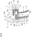
FIG. 2 is an enlarged partial exploded view of a bladder of the first embodiment; -
FIG. 3 is an enlarged partial exploded view of the bladder and a holder of the first embodiment; -
FIG. 4 is an enlarged partial view of the state in which the bladder and the holder are attached to a shell in the first embodiment; -
FIG. 5 is a perspective view showing a second embodiment of the accumulator according to the present invention; -
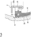
FIG. 6 is an enlarged partial exploded view of a bladder of the second embodiment; and -
FIG. 7 is an enlarged partial view of the state in which the bladder and a holder are attached to a shell in the second embodiment. - The embodiments of the accumulator according to the present invention will be described below with reference to examples.
- The first embodiment of the accumulator will be described with reference to
FIGS. 1 to 5 . A right-to-left direction as viewed in the plane of paper ofFIG. 1 will be hereinafter referred to as a width direction of the accumulator, and an upper-to-lower direction as viewed in the plane of paper will be hereinafter referred to as an upper-to-lower direction of the accumulator. - A reference numeral 1 of
FIG. 1 represents the accumulator to which the present invention has been applied, and a peripheral edge portion of abladder 3 is in close contact with an innerperipheral face 2a of a substantially hollowspherical shell 2 to divide an internal space of theshell 2 into a gas chamber G and a liquid chamber R. - According to properties required for the gas chamber G and the liquid chamber R, the
bladder 3 includes afirst bladder 4 made of a liquid resistant rubber material and placed on the side of the liquid chamber R, and asecond bladder 5 made of a rubber material having favorable gas shielding properties and placed on the side of the gas chamber G. Moreover, theshell 2 is provided in a bottom portion of with an opening 2b, and aliquid port member 25 is welded and fixed to the opening 2b. On the other hand, agas plug 26 is detachably disposed at an upper portion of theshell 2 in opposition to the opening 2b. - As illustrated in
FIGS. 1 and2 , thefirst bladder 4 is disposed such that aperipheral edge portion 6 thereof is positioned on an outer diameter side of aperipheral edge portion 7 of thesecond bladder 5 positioned on an inner diameter side. Moreover, as illustrated inFIGS. 1 and3 , a ring-shaped holder 8 is further disposed on the inner diameter side. As illustrated inFIG. 1 , theperipheral edge portion 6 of thefirst bladder 4 and theperipheral edge portion 7 of thesecond bladder 5 are pressed by the ring-shaped holder 8 against the innerperipheral face 2a of theshell 2, so that theperipheral edge portions peripheral face 2a. - Moreover, a ring 9 (a rigid member) continuously extending in a circumferential direction is disposed between the
peripheral edge portion 6 of thefirst bladder 4 and theperipheral edge portion 7 of thesecond bladder 5. Thering 9 is formed of a rigid body (e.g., a body made of metal) having a higher stiffness than those of theperipheral edge portion 6 of thefirst bladder 4 and theperipheral edge portion 7 of thesecond bladder 5, and has a substantially rectangular cross section. - The
peripheral edge portion 7 of thesecond bladder 5 is provided with a fitting recessedportion 15 having a substantially square U-shape in cross section. The fittingrecessed portion 15 includes abottom portion 12 extending substantially at right angles inward in the radial direction from an upper edge of aplanar portion 11 facing aplanar portion 10 continuously extending downward from theperipheral edge portion 6 of thefirst bladder 4, aside portion 13 extending upward substantially at right angles from an inner-diameter-side end portion of thebottom portion 12, and anupper portion 14 extending outward in the radial direction from an upper end of theside portion 13. - The
peripheral edge portion 6 of thefirst bladder 4 includes a raisedprojection 16 extending substantially at right angles inward in the radial direction from an upper edge of theplanar portion 10 along the innerperipheral face 2a of theshell 2, and the structure is made such that the raisedprojection 16 is fitted into the fitting recessedportion 15 of thesecond bladder 5. - As illustrated in
FIG. 3 , the above-describedring 9 is embedded to fill a clearance between the fitting recessedportion 15 of thesecond bladder 5 and the raisedprojection 16 of thefirst bladder 4. With a combination of these three members, theperipheral edge portion 6 of thefirst bladder 4 and theperipheral edge portion 7 of thesecond bladder 5 are brought into a fitted state, and relative movement of theperipheral edge portion 6 of thefirst bladder 4 and theperipheral edge portion 7 of thesecond bladder 5 in the upper-to-lower direction is restricted. With the fitted state between theperipheral edge portion 6 of thefirst bladder 4 and theperipheral edge portion 7 of thesecond bladder 5, four sides of thering 9 are brought into contact with an innerperipheral face 10a of theplanar portion 10 of thefirst bladder 4, alower face 16a of the raisedprojection 16 of thefirst bladder 4, anupper face 12a of thebottom portion 12 of the fitting recessedportion 15 of thesecond bladder 5, and an outerperipheral face 13a of theside portion 13 of thesecond bladder 5, respectively. - Since the
peripheral edge portion 6 of thefirst bladder 4 and theperipheral edge portion 7 of thesecond bladder 5 are brought into the fitted state as described above, thering 9 is embedded in a fitting portion such that the four sides of thering 9 respectively are brought into contact with an innerperipheral face 10a of theplanar portion 10 of thefirst bladder 4, thelower face 16a of the raisedprojection 16 of thefirst bladder 4, theupper face 12a of thebottom portion 12 of the fitting recessedportion 15 of thesecond bladder 5, and the outerperipheral face 13a of theside portion 13 of thesecond bladder 5. Thus, theperipheral edge portion 6 of thefirst bladder 4, theperipheral edge portion 7 of thesecond bladder 5, and thering 9 can be easily assembled with astep 23 of theshell 2. - The
peripheral edge portion 6 of thefirst bladder 4 is provided, on the outerperipheral face 10b of theplanar portion 10 located slightly lower than an upper edge of theperipheral edge portion 6, with a firstannular protrusion 17 protruding outward in the radial direction. - Moreover, the
second bladder 5 is provided with a secondannular protrusion 18 substantially at the center of, in the upper-to-lower direction, an innerperipheral face 13b of theside portion 13 of the fitting recessedportion 15. A radially outer edge of theupper portion 14 of the fitting recessedportion 15 forms a thirdannular protrusion 19 protruding outward in the radial direction from the outerperipheral face 10b of thefirst bladder 4 along the innerperipheral face 2a of the shell 2 (seeFIG. 3 ). - As illustrated in
FIGS. 3 and4 , in the state in which theperipheral edge portion 6 of thefirst bladder 4 and theperipheral edge portion 7 of thesecond bladder 5 are fitted together, the ring-shapedholder 8 is attached to the inner diameter side of the second bladder. Theholder 8 has the following structure: theholder 8 is formed of a rigid body made of, for example, metal, and has aside portion 20 in surface contact with the innerperipheral face 13b of theside portion 13 of thesecond bladder 5; a lower end of theside portion 20 is bent upward to the outer diameter side to form alower piece 21; and anend portion 21a of thelower piece 21 is in contact with alower face 12b of thebottom portion 12 of thesecond bladder 5. Thus, downward movement of theperipheral edge portion 7 of thesecond bladder 5 fitted onto theperipheral edge portion 6 of thefirst bladder 4 is restricted. Moreover, theholder 8 has anupper piece 22 extending substantially at right angles outward in the radial direction from an upper end of theside portion 20, and a lower face 22a of theupper piece 22 is in surface contact with anupper face 14a of theupper portion 14 of thesecond bladder 5. With this configuration, upward movement of theperipheral edge portion 7 of thesecond bladder 5 fitted onto theperipheral edge portion 6 of thefirst bladder 4 is restricted. - As illustrated in
FIGS. 3 and4 , thestep 23 is formed substantially at the center of, in the upper-to-lower direction, the innerperipheral face 2a of theshell 2, at which thebladder 3 is disposed. The innerperipheral face 2a has a diameter slightly smaller at an upper portion with respect to thestep 23 than at a lower portion thereof. An outer-diameter-side end portion 22b of theupper piece 22 of theholder 8 has a greater outer diameter than that of the upper portion of the inner peripheral face of the shell with respect to thestep 23. Thus, an upper face 22c of theupper piece 22 contacts alower face 23a of thestep 23, thereby restricting upward movement of theholder 8. - The outer diameter of the outer-diameter-side end portion of the
upper piece 22 of theholder 8 is substantially the same as the inner diameter of the lower portion of theshell 2 with respect to thestep 23. According to such a configuration, theshell 2 is in a substantially hollow spherical shape, and therefore, the diameter of the lower portion of the innerperipheral face 2a with respect to thestep 23 gradually decreases in a downward direction. Thus, downward movement of theholder 8 is substantially restricted, theholder 8 being configured such that the outer-diameter-side end portion of theupper piece 22 of theholder 8 has substantially the same diameter as the inner diameter of the lower portion with respect to thestep 23. - The outer
peripheral face 10b of theplanar portion 10 of theperipheral edge portion 6 of thefirst bladder 4 is, in a pressure-free state, formed to have a slightly smaller diameter than that of the innerperipheral face 2a of theshell 2, and an outerperipheral face 20a of theside portion 20 of theholder 8 is formed to have a slightly smaller diameter than that of the innerperipheral face 13b of theside portion 13 of the second bladder in the pressure-free state. Thus, in the state in which theholder 8 is attached, theperipheral edge portion 6 of thefirst bladder 4 and theperipheral edge portion 7 of thesecond bladder 5 are compressed by the innerperipheral face 2a of theshell 2 and the outerperipheral face 20a of theside portion 20 of theholder 8. Consequently, theshell 2, thefirst bladder 4, thesecond bladder 5, and theholder 8 are integrally held by repulsion of thefirst bladder 4 and thesecond bladder 5 as elastic bodies. - As illustrated in
FIG. 4 , thering 9 is disposed between theperipheral edge portion 6 of thefirst bladder 4 and theperipheral edge portion 7 of thesecond bladder 5 and between the innerperipheral face 2a of theshell 2 and the outerperipheral face 20a of theside portion 20 of theholder 8. Thus, the total thickness of theperipheral edge portion 6 of thefirst bladder 4 and theperipheral edge portion 7 of thesecond bladder 5 at the position at which thering 9 is disposed (i.e., the total of the thickness T2 of theplanar portion 10 of theperipheral edge portion 6 of thefirst bladder 4 and the thickness T3 of theside portion 13 of theperipheral edge portion 7 of the second bladder 5) is smaller than the distance between the innerperipheral face 2a of theshell 2 and the outerperipheral face 20a of theside portion 20 of the holder 8 (i.e., the total horizontal thickness T1 of theperipheral edge portion 6 of thefirst bladder 4 and theperipheral edge portion 7 of thesecond bladder 5 in the fitted state between theperipheral edge portion 6 of thefirst bladder 4 and theperipheral edge portion 7 of thesecond bladder 5 at a position at which thering 9 is not disposed). - The accumulator 1 has such a structure that the accumulator 1 receives pressure from the side of the liquid chamber R and the side of the gas chamber G to operate the
bladder 3 up and down. Thus, high holding force is required to hold thebladder 3 against such operation. For this reason, theperipheral edge portion 6 of thefirst bladder 4 and theperipheral edge portion 7 of thesecond bladder 5 are thickly formed for the structure in which thelower piece 21 of theholder 8 is locked at thelower face 12b of thebottom portion 12 of thesecond bladder 5. - With this structure, a tightening margin can be, according to the above-described configuration, ensured for the
peripheral edge portion 6 of thefirst bladder 4 and theperipheral edge portion 7 of thesecond bladder 5 at the position at which thering 9 is disposed. Thus, a surface pressure increases, which is generated between the outerperipheral face 10b (a high-sealing region) of theplanar portion 10 of thefirst bladder 4 and the innerperipheral face 2a of theshell 2. In addition, a surface pressure increases, which is generated between the innerperipheral face 13b of theside portion 13 of thesecond bladder 5 and the outerperipheral face 20a of theholder 8. Thus, even sealing performance of the thickperipheral edge portion 6 of thefirst bladder 4 and the thickperipheral edge portion 7 of thesecond bladder 5 can be enhanced, and no liquid flows from the side of the liquid chamber R to the side of the gas chamber G. - Moreover, the axial thickness of the
ring 9 is formed smaller than that of theperipheral edge portion 6 of thefirst bladder 4 and theperipheral edge portion 7 of thesecond bladder 5 at a position pressed by the outerperipheral face 20a of theside portion 20 of theholder 8. Thus, the thickness of theperipheral edge portion 6 of thefirst bladder 4 and theperipheral edge portion 7 of thesecond bladder 5 at the position at which thering 9 is disposed is smaller than the total radial thickness of theperipheral edge portion 6 of thefirst bladder 4 and theperipheral edge portion 7 of thesecond bladder 5 at the position at which thering 9 is not disposed. At such a portion, a compression ratio becomes greater. Thus, the surface pressure locally increases, which is generated between the outerperipheral face 10b (the high-sealing region) of theplanar portion 10 of thefirst bladder 4 and the innerperipheral face 2a of theshell 2 at the above-described portion. This leads to extremely-high sealing performance. - As illustrated in
FIG. 3 , the firstannular protrusion 17 is formed on the outerperipheral face 10b of theplanar portion 10 of thefirst bladder 4 such that a portion of the firstannular protrusion 17 overlaps with the position at which thering 9 is disposed in the horizontal direction. A surface pressure generated between the firstannular protrusion 17 and the innerperipheral face 2a of theshell 2 further locally increases, and therefore, liquid leakage from a space between the firstannular protrusion 17 and the innerperipheral face 2a of theshell 2 toward thesecond bladder 5 is prevented. - Moreover, the surface pressure increases, which is generated between the inner
peripheral face 13b (a high-sealing region) of theside portion 13 of theperipheral edge portion 7 of thesecond bladder 5 and the outerperipheral face 20a of theside portion 20 of theholder 8 at the position at which thering 9 is disposed. This leads to high sealing performance, and prevents gas from flowing from the side of the gas chamber G to the side of the liquid chamber R. - Further, the second
annular protrusion 18 is formed on the innerperipheral face 13b of theside portion 13 of thesecond bladder 5 such that a portion of the secondannular protrusion 18 overlaps with the position at which thering 9 is disposed in the horizontal direction. A surface pressure generated between the secondannular protrusion 18 and the outerperipheral face 20a of theside portion 20 of theholder 8 further locally increases, and therefore, gas leakage from a space between the secondannular protrusion 18 and the outerperipheral face 20a of theside portion 20 of theholder 8 toward thefirst bladder 4 is prevented. - Moreover, the third
annular protrusion 19 is formed on the radially outer edge of theupper portion 14 of the fitting recessedportion 15 of thesecond bladder 5. This particularly prevents gas with small fluid particles from leaking from a space between the thirdannular protrusion 19 and the innerperipheral face 2a of theshell 2 toward thefirst bladder 4. - Further, the
ring 9 is in an endless shape continuously extending in the circumferential direction, and therefore, theperipheral edge portion 6 of thefirst bladder 4 and theperipheral edge portion 7 of thesecond bladder 5 are equally compressed all over the circumference. Thus, high sealing performance can be ensured. Note that thering 9 may be formed in a substantially C-shape with ends, and in this manner, the structure may be made such that theperipheral edge portion 6 of thefirst bladder 4 and theperipheral edge portion 7 of thesecond bladder 5 can be easily attached to thestep 23. - In addition, the cross section of the
ring 9 is in the substantially rectangular shape, and therefore, the high-sealing region corresponding to about the axial width of thering 9 is formed on the fitting portion between theperipheral edge portion 6 of thefirst bladder 4 and theperipheral edge portion 7 of thesecond bladder 5. Thus, a sufficient deformation margin can be provided for theperipheral edge portion 6 of thefirst bladder 4 and theperipheral edge portion 7 of thesecond bladder 5 at the position at which thering 9 is disposed. Further, the high-sealing region can be formed wide in the axial direction of thering 9, and therefore, high sealing performance can be ensured. - Moreover, the total horizontal thickness T1 of the
peripheral edge portion 6 of thefirst bladder 4 and theperipheral edge portion 7 of thesecond bladder 5 in the fitted state is greater than a distance T4 from an outer peripheral face of thelower piece 21 formed on the lower end of theside portion 20 of theholder 8 to the inner peripheral face of the shell. This suppresses theperipheral edge portion 6 of thefirst bladder 4 and theperipheral edge portion 7 of thesecond bladder 5 in the fitted state from detaching from a space between the outerperipheral face 20a of theside portion 20 of theholder 8 and the innerperipheral face 2a of theshell 2. - Further, the
ring 9 is embedded in the fitting portion between theperipheral edge portion 6 of thefirst bladder 4 and theperipheral edge portion 7 of thesecond bladder 5. Thus, in addition to a high coefficient of friction of the portions respectively in contact with the innerperipheral face 2a of theshell 2 and the outerperipheral face 20a of theside portion 20 of theholder 8, thelower piece 21 of theside portion 20 of theholder 8 is positioned such that a portion of thelower piece 21 below thering 9 overlaps with thering 9 in a view from upper or lower side. This suppresses theperipheral edge portion 6 of thefirst bladder 4 and theperipheral edge portion 7 of thesecond bladder 5 in the fitted state from detaching from the space between the outerperipheral face 20a of theside portion 20 of theholder 8 and the innerperipheral face 2a of theshell 2. - In addition, the four sides of the
ring 9 are brought into contact with the innerperipheral face 10a of theplanar portion 10 of thefirst bladder 4, thelower face 16a of the raisedprojection 16 of thefirst bladder 4, theupper face 12a of thebottom portion 12 of the fitting recessedportion 15 of thesecond bladder 5, and the outerperipheral face 13a of theside portion 13 of thesecond bladder 5, respectively. Thus, a surface pressure increases, which is generated between thering 9 and each face in contact with thering 9. This prevents gas and liquid from entering a space between thefirst bladder 4 and thesecond bladder 5. - Next, an accumulator of a second embodiment will be described with reference to
FIGS. 5 to 7 . Note that the same overlapping configuration as that of the above-described embodiment will not be described. - As illustrated in
FIGS. 5 and6 , afirst bladder 34 and asecond bladder 35 are configured such that opposingfaces planar portions peripheral edge portions faces portions ring 39 is fitted into a cavity portion formed by a combination of the recessedportions peripheral edge portion 36 of thefirst bladder 34 and theperipheral edge portion 37 of thesecond bladder 35. - With this structure, the
ring 39 is fitted into any of the recessedportion 45 of theperipheral edge portion 36 of thefirst bladder 34 and the recessedportion 46 of theperipheral edge portion 37 of thesecond bladder 35 in joining between theperipheral edge portion 36 of thefirst bladder 34 and theperipheral edge portion 37 of thesecond bladder 35, and in this manner, can be temporarily held. As a result, the joining process is facilitated. - As illustrated in
FIG. 7 , the total of the thickness T12 of theplanar portion 40 of theperipheral edge portion 36 of thefirst bladder 34 at a position at which thering 39 is disposed and the thickness T13 of theplanar portion 41 of thesecond bladder 35 at the position at which thering 39 is disposed is smaller than the distance T11 between the innerperipheral face 2a of theshell 2 and the outerperipheral face 20a of theside portion 20 of theholder 8. - Moreover, a first
annular protrusion 47 is formed on an outerperipheral face 40b of theplanar portion 40 of thefirst bladder 34 to partially overlap with the position at which thering 39 is disposed, in a view from right or left side. Similarly, a secondannular protrusion 48 is formed on an innerperipheral face 41b of theplanar portion 41 of thesecond bladder 35 to partially overlap with the position at which thering 39 is disposed, in a view from right or left side. Further, a third annular raisedportion 49 is formed above the firstannular protrusion 47 of the outerperipheral face 40b of theplanar portion 40 of thefirst bladder 34. - Note that the
ring 39 is not limited to such a configuration that thering 39 is fitted into the recessedportion 45 of theperipheral edge portion 36 of thefirst bladder 34 and the recessedportion 46 of theperipheral edge portion 37 of thesecond bladder 35, respectively. For example, it may be configured such that the recessed portion is provided only at any of theperipheral edge portion 36 of thefirst bladder 34 and theperipheral edge portion 37 of thesecond bladder 35 and thering 39 is fitted into such a recessed portion. - The embodiments of the present invention have been described above with reference to the drawings. However, a specific configuration is not limited to these embodiments. Even changes and additions made without departing from the gist of the present invention are included in the present invention.
- For example, the ring of each embodiment described above is configured such that the single annular ring is embedded between the peripheral edge portion of the first bladder and the peripheral edge portion of the second bladder. However, the present invention is not limited to such a configuration. For example, it may be configured such that a plurality of rings are embedded with these rings being dispersedly arranged in the circumferential direction of the peripheral edge portions of the first and second bladders. Moreover, the cross-sectional shape of the ring is not limited to the substantially rectangular shape, and may be, for example, a substantially circular shape, a polygonal shape with five or more sides, or a similar shape.
- Moreover, the configuration of the ring has been described, in which the ring is, before the ring is embedded, received in the clearance formed on the fitting portion between the peripheral edge portion of the first bladder and the peripheral edge portion of the second bladder and having the substantially same inner shape as the outer shape of the ring. However, the ring may be formed with an outer shape larger than that of a clearance. Moreover, the present invention is not limited to these configurations. For example, it may be configured such that the clearance is not substantially present and that the peripheral edge portions of the first and second bladders for embedding the ring are, at the fitting portion therebetween, in surface contact with each other without any clearances. In this configuration, the ring may be embedded in the deformation margin of such a fitting portion.
- Further, the first annular raised portion, the second annular raised portion, and the third annular raised portion in the embodiments described above are not limited to the endless shape, and may be each divided into multiple portions. Further, either one of the second annular raised portion or the third annular raised portion is not necessarily provided when sufficient sealing performance can be ensured.
- In addition, the shape of the
shell 2 is not limited to the substantially spherical shape, and may be, e.g., a cylindrical shape. -
- 1
- Accumulator
- 2
- Shell
- 2a
- Inner peripheral face
- 3
- Bladder
- 4
- First bladder
- 5
- Second bladder
- 6
- Peripheral edge portion of first bladder
- 7
- Peripheral edge portion of second bladder
- 8
- Holder
- 9
- Ring
- 10
- First bladder planar portion
- 10a
- First bladder planar portion inner peripheral face
- 10b
- First bladder planar portion outer peripheral face
- 11
- Second bladder planar portion
- 12
- Fitting recessed portion bottom portion
- 12a
- Bottom portion upper face
- 12b
- Bottom portion lower face
- 13
- Fitting recessed portion side portion
- 13a
- Bottom portion outer peripheral face
- 13b
- Bottom portion inner peripheral face
- 14
- Upper portion
- 15
- Fitting recessed portion
- 16
- Fitting recessed portion raised projection
- 17
- First annular protrusion
- 18
- Second annular protrusion
- 19
- Third annular protrusion
- 20
- Holder side portion
- 20a
- Side portion outer peripheral face
- 21
- Holder lower piece
- 22
- Holder upper piece
- 23
- Step
- 23a
- Step lower face
- 34
- First bladder
- 35
- Second bladder
- 36
- First bladder peripheral edge portion
- 37
- Second bladder peripheral edge portion
- 39
- Ring
- 45, 46
- Recessed portion
- 47
- First annular protrusion
- 48
- Second annular protrusion
- G
- Gas chamber
- R
- Liquid chamber
Claims (5)
- An accumulator comprising a shell and a bladder formed of an elastic member and disposed on the inside of a shell to divide an internal space of the shell into a gas chamber and a liquid chamber, characterized in that the bladder comprises:an outer-diameter-side bladder having a peripheral edge portion disposed on an inner peripheral face of the shell; andan inner-diameter-side bladder having a peripheral edge portion disposed on an inner diameter side of the outer-diameter-side bladder,wherein the accumulator further comprises:a holder configured to face the inner peripheral face of the shell to hold, from the inner diameter side, the peripheral edge portion of the outer-diameter-side bladder and the peripheral edge portion of the inner-diameter-side bladder; anda rigid body disposed between the peripheral edge portion of the outer-diameter-side bladder and the peripheral edge portion of the inner-diameter-side bladder and having a higher stiffness than those of the peripheral edge portion of the outer-diameter-side bladder and the peripheral edge portion of the inner-diameter-side bladder.
- The accumulator of claim 1, characterized in that:
the rigid body is in a ring shape continuously extending in a circumferential direction. - The accumulator of claim 1 or 2, characterized in that:
the rigid body is disposed and embedded at a position of fitting between the peripheral edge portion of the inner-diameter-side bladder and the peripheral edge portion of the outer-diameter-side bladder. - The accumulator of any of claims 1 to 3, characterized in that:
the rigid body has a substantially rectangular cross section. - The accumulator of any one of claims 1 to 4, characterized in that:an annular raised portion protruding inward in the radial direction is provided at a portion of the inner-diameter-side bladder at which the rigid body is disposed, andan annular raised portion protruding outward in the radial direction is provided at a portion of the outer-diameter-side bladder at which the rigid body is disposed.
Applications Claiming Priority (2)
| Application Number | Priority Date | Filing Date | Title |
|---|---|---|---|
| JP2016026080 | 2016-02-15 | ||
| PCT/JP2017/003824 WO2017141719A1 (en) | 2016-02-15 | 2017-02-02 | Accumulator |
Publications (3)
| Publication Number | Publication Date |
|---|---|
| EP3418584A1 true EP3418584A1 (en) | 2018-12-26 |
| EP3418584A4 EP3418584A4 (en) | 2019-08-28 |
| EP3418584B1 EP3418584B1 (en) | 2020-12-23 |
Family
ID=59625705
Family Applications (1)
| Application Number | Title | Priority Date | Filing Date |
|---|---|---|---|
| EP17752982.3A Active EP3418584B1 (en) | 2016-02-15 | 2017-02-02 | Accumulator |
Country Status (3)
| Country | Link |
|---|---|
| EP (1) | EP3418584B1 (en) |
| JP (2) | JP6787990B2 (en) |
| WO (1) | WO2017141719A1 (en) |
Families Citing this family (1)
| Publication number | Priority date | Publication date | Assignee | Title |
|---|---|---|---|---|
| WO2018077638A1 (en) | 2016-10-24 | 2018-05-03 | Philips Lighting Holding B.V. | Presence detection system and method. |
Family Cites Families (3)
| Publication number | Priority date | Publication date | Assignee | Title |
|---|---|---|---|---|
| DE3628608A1 (en) * | 1986-08-22 | 1988-03-03 | Bosch Gmbh Robert | ELASTIC PARTITION |
| US5117873A (en) * | 1990-10-22 | 1992-06-02 | Honda Giken Kogyo Kabushiki Kaisha | Bladder edge seal and holder for hydraulic fluid pressure accumulator |
| JPH0484803U (en) * | 1990-11-29 | 1992-07-23 |
-
2017
- 2017-02-02 JP JP2018500031A patent/JP6787990B2/en active Active
- 2017-02-02 EP EP17752982.3A patent/EP3418584B1/en active Active
- 2017-02-02 WO PCT/JP2017/003824 patent/WO2017141719A1/en not_active Ceased
-
2020
- 2020-08-26 JP JP2020142432A patent/JP6896924B2/en active Active
Also Published As
| Publication number | Publication date |
|---|---|
| JP6787990B2 (en) | 2020-11-18 |
| WO2017141719A1 (en) | 2017-08-24 |
| EP3418584A4 (en) | 2019-08-28 |
| JPWO2017141719A1 (en) | 2018-12-06 |
| JP2020204404A (en) | 2020-12-24 |
| EP3418584B1 (en) | 2020-12-23 |
| JP6896924B2 (en) | 2021-06-30 |
Similar Documents
| Publication | Publication Date | Title |
|---|---|---|
| EP3412941B1 (en) | Gasket | |
| JP6795586B2 (en) | mechanical seal | |
| CN102261464B (en) | Fluid pressure device | |
| US10041562B2 (en) | Sealing structure | |
| JP2004516427A (en) | Improved mechanical face seal | |
| US20120304855A1 (en) | Fluid pressure cylinder | |
| JP6328658B2 (en) | mechanical seal | |
| JP2017048847A (en) | Vibration preventing device | |
| JP2017096309A (en) | Check valve | |
| EP3156700B1 (en) | Mechanical seal | |
| EP3418584B1 (en) | Accumulator | |
| CN104685269A (en) | Sealing means | |
| WO2013125116A1 (en) | Sealing structure | |
| JPWO2016121709A1 (en) | Lining type butterfly valve | |
| JPWO2015111505A1 (en) | Valve stem seal | |
| JP2015196510A (en) | reservoir cap | |
| JP7356655B2 (en) | pipe fittings | |
| JP5116153B2 (en) | Bellows type accumulator | |
| CN113090758B (en) | Shaft sealing device | |
| CN205226145U (en) | clutch master cylinder assembly | |
| JP2016036844A (en) | Shut-off device for metal mold cooling water channel | |
| JP2020097992A (en) | Liquid seal bush | |
| WO2016173543A1 (en) | Elastic sealing element and sealing assembly | |
| JP5195987B2 (en) | Sealing system | |
| JP2015222655A (en) | Seal member and waterproof connector |
Legal Events
| Date | Code | Title | Description |
|---|---|---|---|
| STAA | Information on the status of an ep patent application or granted ep patent |
Free format text: STATUS: THE INTERNATIONAL PUBLICATION HAS BEEN MADE |
|
| PUAI | Public reference made under article 153(3) epc to a published international application that has entered the european phase |
Free format text: ORIGINAL CODE: 0009012 |
|
| STAA | Information on the status of an ep patent application or granted ep patent |
Free format text: STATUS: REQUEST FOR EXAMINATION WAS MADE |
|
| 17P | Request for examination filed |
Effective date: 20180710 |
|
| AK | Designated contracting states |
Kind code of ref document: A1 Designated state(s): AL AT BE BG CH CY CZ DE DK EE ES FI FR GB GR HR HU IE IS IT LI LT LU LV MC MK MT NL NO PL PT RO RS SE SI SK SM TR |
|
| AX | Request for extension of the european patent |
Extension state: BA ME |
|
| DAV | Request for validation of the european patent (deleted) | ||
| DAX | Request for extension of the european patent (deleted) | ||
| A4 | Supplementary search report drawn up and despatched |
Effective date: 20190725 |
|
| RIC1 | Information provided on ipc code assigned before grant |
Ipc: F15B 1/10 20060101ALI20190719BHEP Ipc: F15B 1/14 20060101AFI20190719BHEP |
|
| GRAJ | Information related to disapproval of communication of intention to grant by the applicant or resumption of examination proceedings by the epo deleted |
Free format text: ORIGINAL CODE: EPIDOSDIGR1 |
|
| GRAP | Despatch of communication of intention to grant a patent |
Free format text: ORIGINAL CODE: EPIDOSNIGR1 |
|
| GRAP | Despatch of communication of intention to grant a patent |
Free format text: ORIGINAL CODE: EPIDOSNIGR1 |
|
| STAA | Information on the status of an ep patent application or granted ep patent |
Free format text: STATUS: GRANT OF PATENT IS INTENDED |
|
| INTG | Intention to grant announced |
Effective date: 20200805 |
|
| RIN1 | Information on inventor provided before grant (corrected) |
Inventor name: KAMIMURA, SHINYA Inventor name: MATSUI, KATSUMI |
|
| GRAS | Grant fee paid |
Free format text: ORIGINAL CODE: EPIDOSNIGR3 |
|
| GRAA | (expected) grant |
Free format text: ORIGINAL CODE: 0009210 |
|
| STAA | Information on the status of an ep patent application or granted ep patent |
Free format text: STATUS: THE PATENT HAS BEEN GRANTED |
|
| AK | Designated contracting states |
Kind code of ref document: B1 Designated state(s): AL AT BE BG CH CY CZ DE DK EE ES FI FR GB GR HR HU IE IS IT LI LT LU LV MC MK MT NL NO PL PT RO RS SE SI SK SM TR |
|
| REG | Reference to a national code |
Ref country code: GB Ref legal event code: FG4D |
|
| REG | Reference to a national code |
Ref country code: DE Ref legal event code: R096 Ref document number: 602017030050 Country of ref document: DE |
|
| REG | Reference to a national code |
Ref country code: AT Ref legal event code: REF Ref document number: 1347996 Country of ref document: AT Kind code of ref document: T Effective date: 20210115 |
|
| REG | Reference to a national code |
Ref country code: IE Ref legal event code: FG4D |
|
| PG25 | Lapsed in a contracting state [announced via postgrant information from national office to epo] |
Ref country code: RS Free format text: LAPSE BECAUSE OF FAILURE TO SUBMIT A TRANSLATION OF THE DESCRIPTION OR TO PAY THE FEE WITHIN THE PRESCRIBED TIME-LIMIT Effective date: 20201223 Ref country code: NO Free format text: LAPSE BECAUSE OF FAILURE TO SUBMIT A TRANSLATION OF THE DESCRIPTION OR TO PAY THE FEE WITHIN THE PRESCRIBED TIME-LIMIT Effective date: 20210323 Ref country code: FI Free format text: LAPSE BECAUSE OF FAILURE TO SUBMIT A TRANSLATION OF THE DESCRIPTION OR TO PAY THE FEE WITHIN THE PRESCRIBED TIME-LIMIT Effective date: 20201223 Ref country code: GR Free format text: LAPSE BECAUSE OF FAILURE TO SUBMIT A TRANSLATION OF THE DESCRIPTION OR TO PAY THE FEE WITHIN THE PRESCRIBED TIME-LIMIT Effective date: 20210324 |
|
| REG | Reference to a national code |
Ref country code: AT Ref legal event code: MK05 Ref document number: 1347996 Country of ref document: AT Kind code of ref document: T Effective date: 20201223 |
|
| REG | Reference to a national code |
Ref country code: NL Ref legal event code: MP Effective date: 20201223 |
|
| PG25 | Lapsed in a contracting state [announced via postgrant information from national office to epo] |
Ref country code: BG Free format text: LAPSE BECAUSE OF FAILURE TO SUBMIT A TRANSLATION OF THE DESCRIPTION OR TO PAY THE FEE WITHIN THE PRESCRIBED TIME-LIMIT Effective date: 20210323 Ref country code: SE Free format text: LAPSE BECAUSE OF FAILURE TO SUBMIT A TRANSLATION OF THE DESCRIPTION OR TO PAY THE FEE WITHIN THE PRESCRIBED TIME-LIMIT Effective date: 20201223 Ref country code: LV Free format text: LAPSE BECAUSE OF FAILURE TO SUBMIT A TRANSLATION OF THE DESCRIPTION OR TO PAY THE FEE WITHIN THE PRESCRIBED TIME-LIMIT Effective date: 20201223 |
|
| PG25 | Lapsed in a contracting state [announced via postgrant information from national office to epo] |
Ref country code: NL Free format text: LAPSE BECAUSE OF FAILURE TO SUBMIT A TRANSLATION OF THE DESCRIPTION OR TO PAY THE FEE WITHIN THE PRESCRIBED TIME-LIMIT Effective date: 20201223 Ref country code: HR Free format text: LAPSE BECAUSE OF FAILURE TO SUBMIT A TRANSLATION OF THE DESCRIPTION OR TO PAY THE FEE WITHIN THE PRESCRIBED TIME-LIMIT Effective date: 20201223 |
|
| REG | Reference to a national code |
Ref country code: LT Ref legal event code: MG9D |
|
| PG25 | Lapsed in a contracting state [announced via postgrant information from national office to epo] |
Ref country code: SM Free format text: LAPSE BECAUSE OF FAILURE TO SUBMIT A TRANSLATION OF THE DESCRIPTION OR TO PAY THE FEE WITHIN THE PRESCRIBED TIME-LIMIT Effective date: 20201223 Ref country code: LT Free format text: LAPSE BECAUSE OF FAILURE TO SUBMIT A TRANSLATION OF THE DESCRIPTION OR TO PAY THE FEE WITHIN THE PRESCRIBED TIME-LIMIT Effective date: 20201223 Ref country code: EE Free format text: LAPSE BECAUSE OF FAILURE TO SUBMIT A TRANSLATION OF THE DESCRIPTION OR TO PAY THE FEE WITHIN THE PRESCRIBED TIME-LIMIT Effective date: 20201223 Ref country code: CZ Free format text: LAPSE BECAUSE OF FAILURE TO SUBMIT A TRANSLATION OF THE DESCRIPTION OR TO PAY THE FEE WITHIN THE PRESCRIBED TIME-LIMIT Effective date: 20201223 Ref country code: SK Free format text: LAPSE BECAUSE OF FAILURE TO SUBMIT A TRANSLATION OF THE DESCRIPTION OR TO PAY THE FEE WITHIN THE PRESCRIBED TIME-LIMIT Effective date: 20201223 Ref country code: PT Free format text: LAPSE BECAUSE OF FAILURE TO SUBMIT A TRANSLATION OF THE DESCRIPTION OR TO PAY THE FEE WITHIN THE PRESCRIBED TIME-LIMIT Effective date: 20210423 Ref country code: RO Free format text: LAPSE BECAUSE OF FAILURE TO SUBMIT A TRANSLATION OF THE DESCRIPTION OR TO PAY THE FEE WITHIN THE PRESCRIBED TIME-LIMIT Effective date: 20201223 |
|
| PG25 | Lapsed in a contracting state [announced via postgrant information from national office to epo] |
Ref country code: AT Free format text: LAPSE BECAUSE OF FAILURE TO SUBMIT A TRANSLATION OF THE DESCRIPTION OR TO PAY THE FEE WITHIN THE PRESCRIBED TIME-LIMIT Effective date: 20201223 Ref country code: PL Free format text: LAPSE BECAUSE OF FAILURE TO SUBMIT A TRANSLATION OF THE DESCRIPTION OR TO PAY THE FEE WITHIN THE PRESCRIBED TIME-LIMIT Effective date: 20201223 |
|
| REG | Reference to a national code |
Ref country code: DE Ref legal event code: R097 Ref document number: 602017030050 Country of ref document: DE |
|
| PG25 | Lapsed in a contracting state [announced via postgrant information from national office to epo] |
Ref country code: MC Free format text: LAPSE BECAUSE OF FAILURE TO SUBMIT A TRANSLATION OF THE DESCRIPTION OR TO PAY THE FEE WITHIN THE PRESCRIBED TIME-LIMIT Effective date: 20201223 Ref country code: IS Free format text: LAPSE BECAUSE OF FAILURE TO SUBMIT A TRANSLATION OF THE DESCRIPTION OR TO PAY THE FEE WITHIN THE PRESCRIBED TIME-LIMIT Effective date: 20210423 |
|
| REG | Reference to a national code |
Ref country code: BE Ref legal event code: MM Effective date: 20210228 |
|
| PG25 | Lapsed in a contracting state [announced via postgrant information from national office to epo] |
Ref country code: CH Free format text: LAPSE BECAUSE OF NON-PAYMENT OF DUE FEES Effective date: 20210228 Ref country code: AL Free format text: LAPSE BECAUSE OF FAILURE TO SUBMIT A TRANSLATION OF THE DESCRIPTION OR TO PAY THE FEE WITHIN THE PRESCRIBED TIME-LIMIT Effective date: 20201223 Ref country code: LI Free format text: LAPSE BECAUSE OF NON-PAYMENT OF DUE FEES Effective date: 20210228 Ref country code: IT Free format text: LAPSE BECAUSE OF FAILURE TO SUBMIT A TRANSLATION OF THE DESCRIPTION OR TO PAY THE FEE WITHIN THE PRESCRIBED TIME-LIMIT Effective date: 20201223 Ref country code: LU Free format text: LAPSE BECAUSE OF NON-PAYMENT OF DUE FEES Effective date: 20210202 |
|
| PLBE | No opposition filed within time limit |
Free format text: ORIGINAL CODE: 0009261 |
|
| STAA | Information on the status of an ep patent application or granted ep patent |
Free format text: STATUS: NO OPPOSITION FILED WITHIN TIME LIMIT |
|
| GBPC | Gb: european patent ceased through non-payment of renewal fee |
Effective date: 20210323 |
|
| PG25 | Lapsed in a contracting state [announced via postgrant information from national office to epo] |
Ref country code: DK Free format text: LAPSE BECAUSE OF FAILURE TO SUBMIT A TRANSLATION OF THE DESCRIPTION OR TO PAY THE FEE WITHIN THE PRESCRIBED TIME-LIMIT Effective date: 20201223 |
|
| 26N | No opposition filed |
Effective date: 20210924 |
|
| PG25 | Lapsed in a contracting state [announced via postgrant information from national office to epo] |
Ref country code: GB Free format text: LAPSE BECAUSE OF NON-PAYMENT OF DUE FEES Effective date: 20210323 Ref country code: FR Free format text: LAPSE BECAUSE OF NON-PAYMENT OF DUE FEES Effective date: 20210223 Ref country code: ES Free format text: LAPSE BECAUSE OF FAILURE TO SUBMIT A TRANSLATION OF THE DESCRIPTION OR TO PAY THE FEE WITHIN THE PRESCRIBED TIME-LIMIT Effective date: 20201223 Ref country code: IE Free format text: LAPSE BECAUSE OF NON-PAYMENT OF DUE FEES Effective date: 20210202 |
|
| PG25 | Lapsed in a contracting state [announced via postgrant information from national office to epo] |
Ref country code: SI Free format text: LAPSE BECAUSE OF FAILURE TO SUBMIT A TRANSLATION OF THE DESCRIPTION OR TO PAY THE FEE WITHIN THE PRESCRIBED TIME-LIMIT Effective date: 20201223 |
|
| PG25 | Lapsed in a contracting state [announced via postgrant information from national office to epo] |
Ref country code: IS Free format text: LAPSE BECAUSE OF FAILURE TO SUBMIT A TRANSLATION OF THE DESCRIPTION OR TO PAY THE FEE WITHIN THE PRESCRIBED TIME-LIMIT Effective date: 20210423 |
|
| PG25 | Lapsed in a contracting state [announced via postgrant information from national office to epo] |
Ref country code: BE Free format text: LAPSE BECAUSE OF NON-PAYMENT OF DUE FEES Effective date: 20210228 |
|
| PG25 | Lapsed in a contracting state [announced via postgrant information from national office to epo] |
Ref country code: CY Free format text: LAPSE BECAUSE OF FAILURE TO SUBMIT A TRANSLATION OF THE DESCRIPTION OR TO PAY THE FEE WITHIN THE PRESCRIBED TIME-LIMIT Effective date: 20201223 |
|
| PG25 | Lapsed in a contracting state [announced via postgrant information from national office to epo] |
Ref country code: HU Free format text: LAPSE BECAUSE OF FAILURE TO SUBMIT A TRANSLATION OF THE DESCRIPTION OR TO PAY THE FEE WITHIN THE PRESCRIBED TIME-LIMIT; INVALID AB INITIO Effective date: 20170202 |
|
| PG25 | Lapsed in a contracting state [announced via postgrant information from national office to epo] |
Ref country code: MK Free format text: LAPSE BECAUSE OF FAILURE TO SUBMIT A TRANSLATION OF THE DESCRIPTION OR TO PAY THE FEE WITHIN THE PRESCRIBED TIME-LIMIT Effective date: 20201223 |
|
| PG25 | Lapsed in a contracting state [announced via postgrant information from national office to epo] |
Ref country code: MT Free format text: LAPSE BECAUSE OF FAILURE TO SUBMIT A TRANSLATION OF THE DESCRIPTION OR TO PAY THE FEE WITHIN THE PRESCRIBED TIME-LIMIT Effective date: 20201223 |
|
| PG25 | Lapsed in a contracting state [announced via postgrant information from national office to epo] |
Ref country code: TR Free format text: LAPSE BECAUSE OF FAILURE TO SUBMIT A TRANSLATION OF THE DESCRIPTION OR TO PAY THE FEE WITHIN THE PRESCRIBED TIME-LIMIT Effective date: 20201223 |
|
| PGFP | Annual fee paid to national office [announced via postgrant information from national office to epo] |
Ref country code: DE Payment date: 20251230 Year of fee payment: 10 |