EP3418579A1 - Compressor impeller - Google Patents
Compressor impeller Download PDFInfo
- Publication number
- EP3418579A1 EP3418579A1 EP16896867.5A EP16896867A EP3418579A1 EP 3418579 A1 EP3418579 A1 EP 3418579A1 EP 16896867 A EP16896867 A EP 16896867A EP 3418579 A1 EP3418579 A1 EP 3418579A1
- Authority
- EP
- European Patent Office
- Prior art keywords
- compressor impeller
- heat shield
- boss portion
- back surface
- shield portion
- Prior art date
- Legal status (The legal status is an assumption and is not a legal conclusion. Google has not performed a legal analysis and makes no representation as to the accuracy of the status listed.)
- Granted
Links
Images




Classifications
-
- F—MECHANICAL ENGINEERING; LIGHTING; HEATING; WEAPONS; BLASTING
- F04—POSITIVE - DISPLACEMENT MACHINES FOR LIQUIDS; PUMPS FOR LIQUIDS OR ELASTIC FLUIDS
- F04D—NON-POSITIVE-DISPLACEMENT PUMPS
- F04D29/00—Details, component parts, or accessories
- F04D29/26—Rotors specially for elastic fluids
- F04D29/28—Rotors specially for elastic fluids for centrifugal or helico-centrifugal pumps for radial-flow or helico-centrifugal pumps
- F04D29/284—Rotors specially for elastic fluids for centrifugal or helico-centrifugal pumps for radial-flow or helico-centrifugal pumps for compressors
-
- F—MECHANICAL ENGINEERING; LIGHTING; HEATING; WEAPONS; BLASTING
- F04—POSITIVE - DISPLACEMENT MACHINES FOR LIQUIDS; PUMPS FOR LIQUIDS OR ELASTIC FLUIDS
- F04D—NON-POSITIVE-DISPLACEMENT PUMPS
- F04D29/00—Details, component parts, or accessories
- F04D29/02—Selection of particular materials
- F04D29/023—Selection of particular materials especially adapted for elastic fluid pumps
-
- F—MECHANICAL ENGINEERING; LIGHTING; HEATING; WEAPONS; BLASTING
- F04—POSITIVE - DISPLACEMENT MACHINES FOR LIQUIDS; PUMPS FOR LIQUIDS OR ELASTIC FLUIDS
- F04D—NON-POSITIVE-DISPLACEMENT PUMPS
- F04D29/00—Details, component parts, or accessories
- F04D29/58—Cooling; Heating; Diminishing heat transfer
- F04D29/582—Cooling; Heating; Diminishing heat transfer specially adapted for elastic fluid pumps
- F04D29/5853—Cooling; Heating; Diminishing heat transfer specially adapted for elastic fluid pumps heat insulation or conduction
-
- F—MECHANICAL ENGINEERING; LIGHTING; HEATING; WEAPONS; BLASTING
- F05—INDEXING SCHEMES RELATING TO ENGINES OR PUMPS IN VARIOUS SUBCLASSES OF CLASSES F01-F04
- F05C—INDEXING SCHEME RELATING TO MATERIALS, MATERIAL PROPERTIES OR MATERIAL CHARACTERISTICS FOR MACHINES, ENGINES OR PUMPS OTHER THAN NON-POSITIVE-DISPLACEMENT MACHINES OR ENGINES
- F05C2251/00—Material properties
- F05C2251/04—Thermal properties
- F05C2251/048—Heat transfer
-
- F—MECHANICAL ENGINEERING; LIGHTING; HEATING; WEAPONS; BLASTING
- F05—INDEXING SCHEMES RELATING TO ENGINES OR PUMPS IN VARIOUS SUBCLASSES OF CLASSES F01-F04
- F05D—INDEXING SCHEME FOR ASPECTS RELATING TO NON-POSITIVE-DISPLACEMENT MACHINES OR ENGINES, GAS-TURBINES OR JET-PROPULSION PLANTS
- F05D2240/00—Components
- F05D2240/10—Stators
- F05D2240/15—Heat shield
-
- F—MECHANICAL ENGINEERING; LIGHTING; HEATING; WEAPONS; BLASTING
- F05—INDEXING SCHEMES RELATING TO ENGINES OR PUMPS IN VARIOUS SUBCLASSES OF CLASSES F01-F04
- F05D—INDEXING SCHEME FOR ASPECTS RELATING TO NON-POSITIVE-DISPLACEMENT MACHINES OR ENGINES, GAS-TURBINES OR JET-PROPULSION PLANTS
- F05D2250/00—Geometry
- F05D2250/10—Two-dimensional
- F05D2250/14—Two-dimensional elliptical
- F05D2250/141—Two-dimensional elliptical circular
Definitions
- the present disclosure relates to a compressor impeller.
- the compressor impeller includes a boss portion, and a plurality of vane portions disposed at intervals in the circumferential direction on the peripheral surface of the boss portion.
- FIG. 7 is a diagram showing the distribution of air temperature on the front side (the side where the vanes 004 are provided) of the boss portion 002 of the compressor impeller 050, during operation of the compressor used for the turbocharger.
- FIG. 8 is a diagram showing the distribution of air temperature in the gap on the back side (the gap in the axial direction between the back side of the boss portion and the stationary portion of the casing or the like) of the boss portion 002 of the compressor impeller 050, during operation of the compressor.
- FIG. 9 is a diagram showing the distribution of the metal temperature of the compressor impeller 050 during operation of the compressor.
- FIGs. 7 to 9 are diagrams schematically showing the result of thermal analysis by the present inventors, which are not known at the time of filing of the present application.
- the temperature of air compressed by the compressor impeller 050 increases, and thus the air temperature on the discharge side (outer side in the radial direction) of the compressor impeller 050 is higher than the air temperature on the intake side (inner side in the radial direction) of the compressor impeller 050. Furthermore, a part of discharge air flows into the gap on the back side of the boss portion 002. Thus, as shown in FIG. 8 , the air in the gap is heated further by friction loss with the back surface 002b of the boss portion 002, and heats the back surface 002b of the boss portion 002.
- the temperatures of the entire boss portion 002 and the vane portions 004 disposed around the boss portion 002 increase due to heat transmission from the back surface 002 of the boss portion 002 to the front side (compressor inlet side) of the boss portion 002.
- the air flowing along the compressor impeller 050 is heated from heat transmission from the boss portion 002 and the vane portion 004 (in particular, heat transmission at the compressor inlet side where the temperature difference between the air and the compressor impeller 050 tends to increase), thus obtaining an increased temperature.
- Patent Document 1 JP2934530B
- the present invention was made in view of the above problem, and an object is to provide a compressor impeller whereby it is possible to suppress a temperature increase of a back surface of a boss portion of a compressor impeller, while preventing the configuration of the casing side from becoming complex.
- a compressor impeller whereby it is possible to suppress a temperature increase of a back surface of a boss portion of the compressor impeller, while preventing the configuration of the casing side from becoming complex.
- an expression of relative or absolute arrangement such as “in a direction”, “along a direction”, “parallel”, “orthogonal”, “centered”, “concentric” and “coaxial” shall not be construed as indicating only the arrangement in a strict literal sense, but also includes a state where the arrangement is relatively displaced by a tolerance, or by an angle or a distance whereby it is possible to achieve the same function.
- an expression of an equal state such as “same” “equal” and “uniform” shall not be construed as indicating only the state in which the feature is strictly equal, but also includes a state in which there is a tolerance or a difference that can still achieve the same function.
- an expression of a shape such as a rectangular shape or a cylindrical shape shall not be construed as only the geometrically strict shape, but also includes a shape with unevenness or chamfered corners within the range in which the same effect can be achieved.
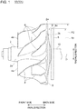
- FIG. 1 is a side view of a compressor impeller 50 (50A) according to an embodiment of the present invention.
- FIG. 2 is a side view of a compressor impeller 50 (50B) according to an embodiment of the present invention.
- FIG. 3 is a side view of a compressor impeller 50 (50C) according to an embodiment of the present invention.
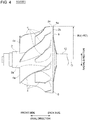
- FIG. 4 is a side view of a compressor impeller 50 (50D) according to an embodiment of the present invention.
- FIG. 5 is a side view of a compressor impeller 50 (50E) according to an embodiment of the present invention.
- FIG. 6 is a side view of a compressor impeller 50 (50F) according to an embodiment of the present invention.
- the circumferential direction of the compressor impeller 50 is referred to as merely “circumferential direction”
- the radial direction of the compressor impeller 50 is referred to as merely “radial direction”
- the axial direction of the compressor impeller 50 is referred to as merely “axial direction”.
- the compressor impeller 50 can be suitably used as a compressor for a small-sized turbocharger for automobiles, for instance.
- the compressor impeller 50 (50A to 50F) includes a shaft 10, a compressor impeller body portion 6 including a boss portion 2 (hub portion) mounted to the shaft 10 and a plurality of vane portions 4 disposed at intervals in the circumferential direction on the peripheral surface 2a of the boss portion 2, and a heat shield portion 8 disposed on the side of the back surface 2b of the boss portion 2 and configured to rotate with the compressor impeller body portion 6.
- the compressor impeller body portion 6 and the heat shield portion 8 are configured to rotate integrally with the shaft portion 10.
- the heat shield portion 8 extends in the radial direction. Furthermore, in the compressor impeller 50 (50A to 50C) shown in FIGs. 1 to 3 , the heat shield portion 8 is fixed to the shaft 10, and thereby configured to rotate with the compressor impeller body portion 6. In the compressor impeller 50 (50D to 50F) shown in FIGs. 4 to 6 , the heat shield portion 8 is fixed to back surface 2b of the boss portion 2, and thereby configured to rotate with the compressor impeller body portion 6.
- the heat shield portion 8 is formed to have an annular shape around the shaft 10.
- the heat shield portion 8 is formed over the entire region in the circumferential direction of the compressor impeller 50, and thus it is possible to suppress heating of the back surface 2b of the boss portion 2 due to friction between the back surface 2b of the boss portion 2 and air effectively with the heat shield portion 8.
- the heat shield portion 8 is formed of a different material from the compressor impeller body portion 6.
- the heat shield portion 8 is formed of a material having a lower thermal conductivity than the compressor impeller body portion 6.
- the heat shield portion 8 formed of a material having a lower thermal conductivity than the compressor impeller body portion 6 suppresses heat transmission from the air toward the boss portion 2.
- the heat shield portion 8 formed of a material having a lower thermal conductivity than the compressor impeller body portion 6 suppresses heat transmission from the air toward the boss portion 2.
- the heat shield portion 8 is formed of sheet metal. According to the above configuration, it is possible to achieve a light-weight heat shield portion 8 at low cost.
- the heat shield portion 8 is formed so as to face the back surface 2b of the boss portion 2 via a gap 'g'.
- the compressor impeller body portion 6 and the heat shield portion 8 rotate together, and thereby it is possible to rotate the air in the gap 'g' interposed between the back surface 2b of the boss portion 2 and the heat shield portion 8, with the back surface 2b of the boss portion 2 and the heat shield portion 8. That is, it is possible to make the air in the gap 'g' rotate together with the back surface 2b of the boss portion 2 and the heat shield portion 8 in rotation.
- the friction between the back surface 2b of the boss portion 2 and the air in the gap 'g' is small, and the temperature of the air in the gap 'g' is less likely to rise.
- the heat shield portion 8 is formed to have a flat plate shape along a surface orthogonal to the axial direction. According to the above configuration, it is possible to obtain the above described effect to suppress a temperature increase of the back surface 2b of the boss portion 2 with a simple configuration.
- the heat shield portion 8 has a curved portion 16 having an annular shape which is curved toward the back surface 2b of the boss portion 2 outward in the radial direction.
- the entire heat shield portion 8 is curved toward the back surface 2b of the boss portion 2 outward in the radial direction.
- the curved portion 16 having an annular shape in a range including at least a part of the radially outer portion 14 of the heat shield portion 8.
- the entire heat shield portion 8 is curved toward the back surface 2b of the boss portion 2 outward in the radial direction.
- the heat shield portion 8 has a protruding portion 18 having an annular shape which protrudes toward the back surface 2b of the boss portion 2.
- the protruding portion 18 is formed on the radially outer edge of the heat shield portion 8.
- the heat shield portion 8 is a coating layer coating the back surface 2b of the boss portion 2, including a material having a lower thermal conductivity than the compressor impeller body portion 6. According to the above configuration, it is possible to achieve a light-weight heat shield portion 8 at low cost.
- the heat shield portion 8 is formed integrally with the compressor impeller body portion 6 from the same material, and the gap 'g' is an annular slit 12 disposed between the boss portion 2 and the heat shield portion 8.
- the compressor impeller body portion 6 and the heat shield portion 8 rotate together, and thereby it is possible to rotate the air in the slit 12 between the boss portion 2 and the heat shield portion 8, with the back surface 2b of the boss portion 2 and the heat shield portion 8.
- the friction between the back surface 2b of the boss portion 2 and the air in the slit 12 is small, and the temperature of the air in the slit 12 is less likely to rise.
- the heat shield portion 8 is formed integrally with the compressor impeller body portion 6 from the same material, the heat shield portion 8 can be provided without increasing the number of components, which makes it possible to suppress a size increase and a cost increase of the compressor impeller 50.
- the distance Ri between the radially outer end 8e of the heat shield portion 8 and the rotational axis O of the compressor impeller 50 is not smaller than a half of the distance R2 between the radially outer end 2e of the back surface 2b of the boss portion 2 and the rotational axis O of the compressor impeller 50.
- the temperature of the back surface of the boss portion tends to become relatively high at the radially outer portion of the boss portion.
- the distance Ri is set to be not smaller than a half of the distance R2
- the radially outer end 8e of the heat shield portion 8 is positioned on the inner side, with respect to the radial direction, of the radially outer end 2e of the back surface 2b of the boss portion 2.
- the temperature of air adjacent to the back surface of the boss portion 002 becomes highest at a radial directional position P on the inner side of the radially outer end 002e of the boss portion 002.
- the radially outer end 8e of the heat shield portion 8 is disposed on the inner side, with respect to the radial direction, of the radially outer end 2e of the back surface 2b of the boss portion 2, and thus it is possible to provide the slit 12 from the outer side to the inner side of the radial directional position P with the highest temperature, without increasing the depth 'd' of the slit 12 excessively in view of the strength of the compressor impeller.
- the present invention may be combined to the technique disclosed in in Patent Document 1, that is, the technique of spraying high-pressure cooling air onto the back surface of the boss portion of the compressor impeller to cool the back surface of the boss portion.
- Patent Document 1 the technique of spraying high-pressure cooling air onto the back surface of the boss portion of the compressor impeller to cool the back surface of the boss portion.
- it is possible to reduce the flow rate of cooling gas required to cool the back surface of the boss portion of the compressor impeller to a certain standard, and thus it is possible to simplify the configuration of the supply flow passage for supplying cooling gas.
Landscapes
- Engineering & Computer Science (AREA)
- Mechanical Engineering (AREA)
- General Engineering & Computer Science (AREA)
- Physics & Mathematics (AREA)
- Thermal Sciences (AREA)
- Structures Of Non-Positive Displacement Pumps (AREA)
Abstract
Description
- The present disclosure relates to a compressor impeller.
- Normally, the compressor impeller includes a boss portion, and a plurality of vane portions disposed at intervals in the circumferential direction on the peripheral surface of the boss portion.
-
FIG. 7 is a diagram showing the distribution of air temperature on the front side (the side where thevanes 004 are provided) of theboss portion 002 of thecompressor impeller 050, during operation of the compressor used for the turbocharger.FIG. 8 is a diagram showing the distribution of air temperature in the gap on the back side (the gap in the axial direction between the back side of the boss portion and the stationary portion of the casing or the like) of theboss portion 002 of thecompressor impeller 050, during operation of the compressor.FIG. 9 is a diagram showing the distribution of the metal temperature of thecompressor impeller 050 during operation of the compressor.FIGs. 7 to 9 are diagrams schematically showing the result of thermal analysis by the present inventors, which are not known at the time of filing of the present application. - As shown in
FIG. 7 , the temperature of air compressed by thecompressor impeller 050 increases, and thus the air temperature on the discharge side (outer side in the radial direction) of thecompressor impeller 050 is higher than the air temperature on the intake side (inner side in the radial direction) of thecompressor impeller 050. Furthermore, a part of discharge air flows into the gap on the back side of theboss portion 002. Thus, as shown inFIG. 8 , the air in the gap is heated further by friction loss with theback surface 002b of theboss portion 002, and heats theback surface 002b of theboss portion 002. - As shown in
FIG. 9 , as the temperature of theback surface 002b of theboss portion 002 increases due to the friction loss, the temperatures of theentire boss portion 002 and thevane portions 004 disposed around theboss portion 002 increase due to heat transmission from theback surface 002 of theboss portion 002 to the front side (compressor inlet side) of theboss portion 002. Thus, the air flowing along thecompressor impeller 050 is heated from heat transmission from theboss portion 002 and the vane portion 004 (in particular, heat transmission at the compressor inlet side where the temperature difference between the air and thecompressor impeller 050 tends to increase), thus obtaining an increased temperature. - When the temperature of the air flowing along the
compressor impeller 050 is increased from heat transmission from theboss portion 002 and thevane portion 004, it leads to deterioration of the performance of thecompressor impeller 050, that is, reduction of the compressor pressure ratio and reduction of the compressor efficiency. - In the compressor disclosed in Patent Document 1, high-pressure cooling gas is sprayed onto the back surface of the boss portion of the compressor impeller to cool the back surface of the boss portion, and the compressor efficiency is improved.
- Patent Document 1:
JP2934530B - For the compressor disclosed in Patent Document 1, it is necessary to provide a supply flow passage for the cooling gas on the side of the casing for accommodating the compressor impeller, and thus the casing has a complex structure. In particular, for small-sized compressors used for automobile turbochargers or the like, it is often difficult to provide a casing with a supply flow passage for cooling gas.
- The present invention was made in view of the above problem, and an object is to provide a compressor impeller whereby it is possible to suppress a temperature increase of a back surface of a boss portion of a compressor impeller, while preventing the configuration of the casing side from becoming complex.
-
- (1) According to at least one embodiment of the present invention, a compressor impeller includes: a compressor impeller body portion including a boss portion and a plurality of vane portions disposed at intervals in a circumferential direction on a peripheral surface of the boss portion; and a heat shield portion disposed on a side of a back surface of the boss portion and configured to rotate with the compressor impeller body portion.
According to the above compressor impeller (1), with the heat shield portion that rotates with the compressor impeller body portion, it is possible to suppress a temperature increase of the back surface of the boss portion due to friction between the back surface of the boss portion and air. Accordingly, it is possible to reduce the amount of heat transmitted to the front side (compressor inlet side) of the boss portion from the back surface of the boss portion, and suppress a temperature increase of the boss portion and the vane portion disposed on the peripheral surface of the boss portion. Thus, it is possible to suppress heating of the air flowing along the compressor impeller body portion from heat transmission from the boss portion and the vane portion (in particular, heat transmission at the compressor inlet side where the temperature difference between the air and the compressor impeller body portion tends to increase), and thus it is possible to obtain a highly-efficient compressor impeller whereby it is possible to suppress reduction of the compressor pressure ratio and the compressor efficiency.
Furthermore, like the compressor disclosed in Patent Document 1, it is unnecessary to provide a supply flow passage for the cooling gas on the side of the casing for accommodating the compressor impeller, and thus it is possible to prevent the configuration of the casing from becoming complex. - (2) In some embodiments, in the above compressor impeller (1), the heat shield portion is made of a different material from the compressor impeller body portion.
According to the above compressor impeller (2), by using a suitable material for the heat shield portion, it is possible to effectively suppress a temperature increase of the back surface of the boss portion due to friction between the back surface of the boss portion and air. - (3) In some embodiments, in the above compressor impeller (2), the heat shield portion is made of a material having a lower thermal conductivity than the compressor impeller body portion.
With the above compressor impeller (3), even if the air opposite to the heat shield portion across the boss portion is heated from friction with the heat shield portion in rotation, the heat shield portion formed of a material having a lower thermal conductivity than the compressor impeller body portion suppresses heat transmission from the air toward the boss portion. Thus, it is possible to suppress heating of the back surface of the boss portion effectively. - (4) In some embodiments, in the compressor impeller according to any one of the above (1) to (3), the heat shield portion is made of sheet metal.
With the above compressor impeller (4), it is possible to achieve a light-weight heat shield portion at low cost. - (5) In some embodiments, in the compressor impeller according to any one of the above (1) to (4), the heat shield portion is disposed so as to face the back surface of the boss portion via a gap.
According to the above compressor impeller (5), the compressor impeller body portion and the heat shield portion rotate together, and thereby it is possible to rotate the air in the gap interposed between the back surface of the boss portion and the heat shield portion, with the back surface of the boss portion and the heat shield portion. That is, it is possible to make the air in the gap 'g' rotate together with theback surface 2b of theboss portion 2 and theheat shield portion 8 in rotation. Thus, the friction between the back surface of the boss portion and the air in the gap is small, and the temperature of the air in the gap is less likely to rise. Thus, it is possible to suppress heating of the back surface of the boss portion effectively. - (6) In some embodiments, in the above compressor impeller (2) or (3), the heat shield portion includes a coating layer coating the back surface of the boss portion, the coating layer being formed of a material having a lower thermal conductivity than the compressor impeller body portion.
With the above compressor impeller (6), it is possible to achieve a light-weight heat shield portion at low cost. - (7) In some embodiments, in the above compressor impeller (1), the heat shield portion is formed integrally with the compressor impeller body portion from an identical material, and a slit is disposed between the heat shield portion and the boss portion.
According to the above description (7), the compressor impeller body portion and the heat shield portion rotate together, and thereby it is possible to rotate the air in the slit between the boss portion and the heat shield portion, with the back surface of the boss portion and the heat shield portion. Thus, the friction between the back surface of the boss portion and the air in the slit is small, and the temperature of the air in the slit is less likely to rise. Thus, it is possible to suppress heating of the back surface of the boss portion effectively. Furthermore, since the heat shield portion is formed integrally with the compressor impeller body portion from the same material, the heat shield portion can be provided without increasing the number of components, which makes it possible to suppress a size increase and a cost increase of the compressor impeller. - (8) In some embodiments, in the compressor impeller according to any one of the above (1) to (7), the heat shield portion is formed to have an annular shape.
According to the above compressor impeller (8), the heat shield portion is formed over the entire region in the circumferential direction of the compressor impeller, and thus it is possible to suppress heating of the back surface of the boss portion due to friction between the back surface of the boss portion and air effectively with the heat shield portion. - (9) In some embodiments, in the above compressor impeller (8), a distance between a radially outer end of the heat shield portion and a rotational axis of the compressor impeller is not smaller than a half of a distance between a radially outer end of the back surface of the boss portion and the rotational axis of the compressor impeller.
According to the above compressor impeller (9), it is possible to effectively suppress a temperature increase due to friction with air, for the radially outer portion of the back surface of the boss portion, where the temperature tends to rise, with the heat shield portion. - (10) In some embodiments, in the above compressor impeller (8) or (9), the heat shield portion is formed integrally with the compressor impeller body portion from an identical material, a slit is disposed between the heat shield portion and the boss portion, and a radially outer end of the heat shield portion is positioned on an inner side of a radially outer end of the back surface of the boss portion in a radial direction of the compressor impeller.
According to the above compressor impeller (10), the compressor impeller body portion and the heat shield portion rotate together, and thereby it is possible to rotate the air in the slit between the boss portion and the heat shield portion, with the back surface of the boss portion and the heat shield portion. Thus, the friction between the back surface of the boss portion and the air in the slit is small, and the temperature of the air in the slit is less likely to rise. Thus, it is possible to suppress heating of the back surface of the boss portion effectively.
According to findings of the present inventors, the temperature of air adjacent to the back surface of the boss portion becomes highest at a radial directional position on the inner side of the radially outer end of the boss portion.
In this regard, with the compressor impeller (10), the radially outer end of the heat shield portion is disposed on the inner side, with respect to the radial direction, of the radially outer end of the back surface of the boss portion, and thus it is possible to provide the slit from the outer side to the inner side of the radial directional position with the highest temperature, without increasing the depth of the slit excessively in view of the strength of the compressor impeller. Thus, it is possible to suppress a temperature increase of the back surface of the boss portion effectively while ensuring the strength of the compressor impeller. - (11) In some embodiments, in the compressor impeller according to any one of the above (8) to (10), the heat shield portion is disposed so as to face the back surface of the boss portion via a gap, and the heat shield portion includes a curved portion having an annular shape and curved so as to become closer to the back surface of the boss portion outward in a radial direction of the compressor impeller.
According to the above compressor impeller (11), the heat shield portion facing the back surface of the boss portion via gap has a curved portion having an annular shape which is curved toward the back surface of the boss portion outward in the radial direction of the compressor impeller. Thus, air is more likely to be retained on the radially inner side of the curved portion having an annular shape, and the air in the gap is more likely to rotate with the boss portion and the heat shield portion. Thus, it is possible to effectively reduce the friction between the back surface of the boss portion and the air in the gap, and suppress a temperature increase of the air in the gap. Thus, it is possible to suppress heating of the back surface of the boss portion effectively. - (12) In some embodiments, in the compressor according to any one of the above (8) to (10), the heat shield portion is disposed so as to face the back surface of the boss portion via a gap, and the heat shield portion includes a protruding portion having an annular shape and protruding toward the back surface of the boss portion.
According to the above compressor impeller (12), the heat shield portion facing the back surface of the boss portion via a gap has a protruding portion having an annular shape which protrudes toward the back surface of the boss portion. Thus, air is retained on the inner side of the protruding portion having an annular shape, and the air in the gap is more likely to rotate with the boss portion and the heat shield portion. Thus, it is possible to effectively reduce the friction between the back surface of the boss portion and the air in the gap, and suppress a temperature increase of the air in the gap. Thus, it is possible to suppress heating of the back surface of the boss portion effectively. - According to at least one embodiment of the present invention, it is possible to provide a compressor impeller whereby it is possible to suppress a temperature increase of a back surface of a boss portion of the compressor impeller, while preventing the configuration of the casing side from becoming complex.
-
-
FIG. 1 is a side view of a compressor impeller 50 (50A) according to an embodiment of the present invention. -
FIG. 2 is a side view of a compressor impeller 50 (50B) according to an embodiment of the present invention. -
FIG. 3 is a side view of a compressor impeller 50 (50C) according to an embodiment of the present invention. -
FIG. 4 is a side view of a compressor impeller 50 (50D) according to an embodiment of the present invention. -
FIG. 5 is a side view of a compressor impeller 50 (50E) according to an embodiment of the present invention. -
FIG. 6 is a side view of a compressor impeller 50 (50F) according to an embodiment of the present invention. -
FIG. 7 is a diagram showing the distribution of air temperature on the front side (the side where thevanes 004 are provided) of theboss portion 002 of thecompressor impeller 050, during operation of a compressor. -
FIG. 8 is a diagram showing the distribution of air temperature in the gap on the back side (the gap in the axial direction between the back surface of the boss portion and the stationary portion of the casing or the like) of theboss portion 002 of thecompressor impeller 050, during operation of a compressor. -
FIG. 9 is a diagram showing the distribution of the metal temperature of thecompressor impeller 050 during operation of the compressor. - Embodiments of the present invention will now be described in detail with reference to the accompanying drawings. It is intended, however, that unless particularly identified, dimensions, materials, shapes, relative positions and the like of components described in the embodiments shall be interpreted as illustrative only and not intended to limit the scope of the present invention.
- For instance, an expression of relative or absolute arrangement such as "in a direction", "along a direction", "parallel", "orthogonal", "centered", "concentric" and "coaxial" shall not be construed as indicating only the arrangement in a strict literal sense, but also includes a state where the arrangement is relatively displaced by a tolerance, or by an angle or a distance whereby it is possible to achieve the same function.
- For instance, an expression of an equal state such as "same" "equal" and "uniform" shall not be construed as indicating only the state in which the feature is strictly equal, but also includes a state in which there is a tolerance or a difference that can still achieve the same function.
- Further, for instance, an expression of a shape such as a rectangular shape or a cylindrical shape shall not be construed as only the geometrically strict shape, but also includes a shape with unevenness or chamfered corners within the range in which the same effect can be achieved.
- On the other hand, an expression such as "comprise", "include", "have", "contain" and "constitute" are not intended to be exclusive of other components.
-
FIG. 1 is a side view of a compressor impeller 50 (50A) according to an embodiment of the present invention.FIG. 2 is a side view of a compressor impeller 50 (50B) according to an embodiment of the present invention.FIG. 3 is a side view of a compressor impeller 50 (50C) according to an embodiment of the present invention.FIG. 4 is a side view of a compressor impeller 50 (50D) according to an embodiment of the present invention.FIG. 5 is a side view of a compressor impeller 50 (50E) according to an embodiment of the present invention.FIG. 6 is a side view of a compressor impeller 50 (50F) according to an embodiment of the present invention. - Hereinafter, unless otherwise stated, the circumferential direction of the
compressor impeller 50 is referred to as merely "circumferential direction", the radial direction of thecompressor impeller 50 is referred to as merely "radial direction", and the axial direction of thecompressor impeller 50 is referred to as merely "axial direction". Further, thecompressor impeller 50 can be suitably used as a compressor for a small-sized turbocharger for automobiles, for instance. - In some embodiments, as shown in
FIGs. 1 to 6 for instance, the compressor impeller 50 (50A to 50F) includes ashaft 10, a compressorimpeller body portion 6 including a boss portion 2 (hub portion) mounted to theshaft 10 and a plurality ofvane portions 4 disposed at intervals in the circumferential direction on theperipheral surface 2a of theboss portion 2, and aheat shield portion 8 disposed on the side of theback surface 2b of theboss portion 2 and configured to rotate with the compressorimpeller body portion 6. The compressorimpeller body portion 6 and theheat shield portion 8 are configured to rotate integrally with theshaft portion 10. - In the depicted embodiment, the
heat shield portion 8 extends in the radial direction. Furthermore, in the compressor impeller 50 (50A to 50C) shown inFIGs. 1 to 3 , theheat shield portion 8 is fixed to theshaft 10, and thereby configured to rotate with the compressorimpeller body portion 6. In the compressor impeller 50 (50D to 50F) shown inFIGs. 4 to 6 , theheat shield portion 8 is fixed to backsurface 2b of theboss portion 2, and thereby configured to rotate with the compressorimpeller body portion 6. - According to the above configuration, with the
heat shield portion 8 that rotates with the compressorimpeller body portion 6, it is possible to suppress heating of theback surface 2b of theboss portion 2 due to friction between theback surface 2b of theboss portion 2 and air. Accordingly, it is possible to reduce the amount of heat transmitted to the front side (compressor inlet side, that is, the side of theleading edge 4a of the vane portion 4) of theboss portion 2 from theback surface 2b of theboss portion 2, and suppress a temperature increase of theboss portion 2 and thevane portion 4 disposed on theperipheral surface 2a of theboss portion 2. Thus, it is possible to suppress heating of the air flowing along the compressorimpeller body portion 6 from heat transmission from theboss portion 2 and the vane portion 4 (in particular, heat transmission at the compressor inlet side where the temperature difference between the air and the compressorimpeller body portion 6 tends to increase), and thus it is possible to obtain a highly-efficient compressor impeller 50 whereby it is possible to suppress reduction of the compressor pressure ratio and the compressor efficiency. - Furthermore, like the compressor disclosed in Patent Document 1, it is possible to suppress a temperature increase of the back surface of the boss portion without providing a supply flow passage for the cooling gas on the side of the casing for accommodating the compressor impeller, and thus it is possible to prevent the configuration of the casing from becoming complex.
- In some embodiments, in the compressor impeller 50 (50A to 50F) shown in
FIGs. 1 to 6 , theheat shield portion 8 is formed to have an annular shape around theshaft 10. - According to the above configuration, the
heat shield portion 8 is formed over the entire region in the circumferential direction of thecompressor impeller 50, and thus it is possible to suppress heating of theback surface 2b of theboss portion 2 due to friction between theback surface 2b of theboss portion 2 and air effectively with theheat shield portion 8. - In some embodiments, in the compressor impeller 50 (50A to 50D) shown in
FIGs. 1 to 4 , theheat shield portion 8 is formed of a different material from the compressorimpeller body portion 6. - According to the above configuration, by using a suitable material for the
heat shield portion 8, it is possible to effectively suppress a temperature increase of theback surface 2b of theboss portion 2 due to friction between theback surface 2b of theboss portion 2 and air. - In some embodiments, in the compressor impeller 50 (50A to 50D) shown in
FIGs. 1 to 4 , theheat shield portion 8 is formed of a material having a lower thermal conductivity than the compressorimpeller body portion 6. - With the above configuration, even if the air opposite to the
heat shield portion 8 across the boss portion 2 (the air adjacent to the right side of theheat shield portion 8 in the drawing) is heated from friction with theheat shield portion 8 in rotation, theheat shield portion 8 formed of a material having a lower thermal conductivity than the compressorimpeller body portion 6 suppresses heat transmission from the air toward theboss portion 2. Thus, it is possible to suppress heating of theback surface 2b of theboss portion 2 effectively. - In some embodiments, in the compressor impeller 50 (50A, 50B) shown in
FIGs. 1 and2 for instance, theheat shield portion 8 is formed of sheet metal. According to the above configuration, it is possible to achieve a light-weightheat shield portion 8 at low cost. - In some embodiments, as depicted in
FIGs. 1 to 3 ,5 , and6 , in the compressor impeller 50 (50A to 50C, 50E, 50F), theheat shield portion 8 is formed so as to face theback surface 2b of theboss portion 2 via a gap 'g'. - According to the above configuration, the compressor
impeller body portion 6 and theheat shield portion 8 rotate together, and thereby it is possible to rotate the air in the gap 'g' interposed between theback surface 2b of theboss portion 2 and theheat shield portion 8, with theback surface 2b of theboss portion 2 and theheat shield portion 8. That is, it is possible to make the air in the gap 'g' rotate together with theback surface 2b of theboss portion 2 and theheat shield portion 8 in rotation. Thus, the friction between theback surface 2b of theboss portion 2 and the air in the gap 'g' is small, and the temperature of the air in the gap 'g' is less likely to rise. Thus, it is possible to suppress heating of theback surface 2b of theboss portion 2 effectively. - In some embodiments, as depicted in
FIG. 1 , in the compressor impeller 50 (50A), theheat shield portion 8 is formed to have a flat plate shape along a surface orthogonal to the axial direction. According to the above configuration, it is possible to obtain the above described effect to suppress a temperature increase of theback surface 2b of theboss portion 2 with a simple configuration. - In some embodiments, as depicted in
FIG. 2 , in the compressor impeller 50 (50B), theheat shield portion 8 has acurved portion 16 having an annular shape which is curved toward theback surface 2b of theboss portion 2 outward in the radial direction. In an illustrative embodiment, the entireheat shield portion 8 is curved toward theback surface 2b of theboss portion 2 outward in the radial direction. - According to the above configuration, air is more likely to be retained on the radially inner side of the
curved portion 16 having an annular shape, and the air in the gap 'g' is more likely to rotate with theboss portion 2 and theheat shield portion 8. Thus, it is possible to effectively reduce the friction between theback surface 2b of theboss portion 2 and the air in the gap 'g', and suppress a temperature increase of the air in the gap 'g'. Thus, it is possible to suppress heating of theback surface 2b of theboss portion 2 effectively. - Furthermore, to promote rotation of the air in the gap 'g' with the
boss portion 2 and theheat shield portion 8, it is desirable to form thecurved portion 16 having an annular shape in a range including at least a part of the radiallyouter portion 14 of theheat shield portion 8. In an illustrative embodiment, the entireheat shield portion 8 is curved toward theback surface 2b of theboss portion 2 outward in the radial direction. - In some embodiments, as depicted in
FIG. 3 , in the compressor impeller 50 (50C), theheat shield portion 8 has a protrudingportion 18 having an annular shape which protrudes toward theback surface 2b of theboss portion 2. - According to the above configuration, air is more likely to be retained on the radially inner side of the protruding
portion 18 having an annular shape, and the air in the gap 'g' is more likely to rotate with theboss portion 2 and theheat shield portion 8. Thus, it is possible to effectively reduce the friction between theback surface 2b of theboss portion 2 and the air in the gap 'g', and suppress a temperature increase of the air in the gap 'g'. Thus, it is possible to suppress heating of theback surface 2b of theboss portion 2 effectively. - Furthermore, to promote rotation of the air in the gap 'g' with the
boss portion 2 and theheat shield portion 8, it is desirable to form the protrudingportion 18 having an annular shape on the radiallyouter portion 14 of theheat shield portion 8. In the depicted illustrative embodiment, the protrudingportion 18 is formed on the radially outer edge of theheat shield portion 8. - In some embodiments, in the compressor impeller 50 (50D) shown in
FIG. 4 , theheat shield portion 8 is a coating layer coating theback surface 2b of theboss portion 2, including a material having a lower thermal conductivity than the compressorimpeller body portion 6. According to the above configuration, it is possible to achieve a light-weightheat shield portion 8 at low cost. - In some embodiments, as depicted in
FIGs. 5 and6 , in the compressor impeller 50 (50E, 50F), theheat shield portion 8 is formed integrally with the compressorimpeller body portion 6 from the same material, and the gap 'g' is anannular slit 12 disposed between theboss portion 2 and theheat shield portion 8. - According to the above configuration, the compressor
impeller body portion 6 and theheat shield portion 8 rotate together, and thereby it is possible to rotate the air in theslit 12 between theboss portion 2 and theheat shield portion 8, with theback surface 2b of theboss portion 2 and theheat shield portion 8. Thus, the friction between theback surface 2b of theboss portion 2 and the air in theslit 12 is small, and the temperature of the air in theslit 12 is less likely to rise. Thus, it is possible to suppress heating of theback surface 2b of theboss portion 2 effectively. Furthermore, since theheat shield portion 8 is formed integrally with the compressorimpeller body portion 6 from the same material, theheat shield portion 8 can be provided without increasing the number of components, which makes it possible to suppress a size increase and a cost increase of thecompressor impeller 50. - In some embodiments, as depicted in
FIGs. 1 to 6 , in the compressor impeller 50 (50A to 50F), the distance Ri between the radiallyouter end 8e of theheat shield portion 8 and the rotational axis O of thecompressor impeller 50 is not smaller than a half of the distance R2 between the radiallyouter end 2e of theback surface 2b of theboss portion 2 and the rotational axis O of thecompressor impeller 50. - As depicted in
FIG. 9 , the temperature of the back surface of the boss portion tends to become relatively high at the radially outer portion of the boss portion. Thus, by setting the distance Ri to be not smaller than a half of the distance R2, it is possible to effectively suppress a temperature increase of the radially outer portion of theback surface 2b of theboss portion 2, where the temperature tends to rise, with theheat shield portion 8. - In some embodiments, as depicted in
FIGs. 1 to 3 , and6 , in the compressor impeller 50 (50A to 50F), the radiallyouter end 8e of theheat shield portion 8 is positioned on the inner side, with respect to the radial direction, of the radiallyouter end 2e of theback surface 2b of theboss portion 2. - According to findings of the present inventors, as depicted in
FIG. 8 , the temperature of air adjacent to the back surface of theboss portion 002 becomes highest at a radial directional position P on the inner side of the radiallyouter end 002e of theboss portion 002. - In this regard, with the compressor impeller 50 (50F) depicted in
FIG. 6 , the radiallyouter end 8e of theheat shield portion 8 is disposed on the inner side, with respect to the radial direction, of the radiallyouter end 2e of theback surface 2b of theboss portion 2, and thus it is possible to provide theslit 12 from the outer side to the inner side of the radial directional position P with the highest temperature, without increasing the depth 'd' of theslit 12 excessively in view of the strength of the compressor impeller. Thus, it is possible to suppress a temperature increase of theback surface 2b of theboss portion 2 effectively while ensuring the strength of the compressor impeller 50 (50F). - Embodiments of the present invention were described in detail above, but the present invention is not limited thereto, and various amendments and modifications may be implemented.
- The present invention may be combined to the technique disclosed in in Patent Document 1, that is, the technique of spraying high-pressure cooling air onto the back surface of the boss portion of the compressor impeller to cool the back surface of the boss portion. In this case, it is possible to reduce the flow rate of cooling gas required to cool the back surface of the boss portion of the compressor impeller to a certain standard, and thus it is possible to simplify the configuration of the supply flow passage for supplying cooling gas.
-
- 2
- Boss portion
- 2a
- Peripheral surface
- 2b
- Back surface
- 2e
- Radially outer end
- 4
- Vane portion
- 4a
- Leading edge
- 6
- Compressor impeller body portion
- 8
- Heat shield portion
- 8e
- Radially outer end
- 10
- Shaft portion
- 12
- Slit
- 14
- Radially outer portion
- 16
- Curved portion
- 18
- Protruding portion
- 50
- Compressor impeller
- O
- Rotational axis
- P
- Position
- R1, R2
- Distance
- g
- Gap
Claims (12)
- A compressor impeller, comprising:a compressor impeller body portion including a boss portion and a plurality of vane portions disposed at intervals in a circumferential direction on a peripheral surface of the boss portion; anda heat shield portion disposed on a side of a back surface of the boss portion and configured to rotate with the compressor impeller body portion.
- The compressor impeller according to claim 1,
wherein the heat shield portion is made of a different material from the compressor impeller body portion. - The compressor impeller according to claim 2,
wherein the heat shield portion is made of a material having a lower thermal conductivity than the compressor impeller body portion. - The compressor impeller according to any one of claims 1 to 3,
wherein the heat shield portion is made of sheet metal. - The compressor impeller according to any one of claims 1 to 4,
wherein the heat shield portion is disposed so as to face the back surface of the boss portion via a gap. - The compressor impeller according to claim 2 or 3,
wherein the heat shield portion comprises a coating layer coating the back surface of the boss portion, the coating layer being formed of a material having a lower thermal conductivity than the compressor impeller body portion. - The compressor impeller according to claim 1,
wherein the heat shield portion is formed integrally with the compressor impeller body portion from an identical material, and
wherein a slit is disposed between the heat shield portion and the boss portion. - The compressor impeller according to any one of claims 1 to 7,
the heat shield portion is formed to have an annular shape. - The compressor impeller according to claim 8,
wherein a distance between a radially outer end of the heat shield portion and a rotational axis of the compressor impeller is not smaller than a half of a distance between a radially outer end of the back surface of the boss portion and the rotational axis of the compressor impeller. - The compressor impeller according to claim 8 or 9,
wherein the heat shield portion is formed integrally with the compressor impeller body portion from an identical material,
wherein a slit is disposed between the heat shield portion and the boss portion, and
wherein a radially outer end of the heat shield portion is positioned on an inner side of a radially outer end of the back surface of the boss portion in a radial direction of the compressor impeller. - The compressor impeller according to any one of claims 8 to 10,
wherein the heat shield portion is disposed so as to face the back surface of the boss portion via a gap, and
wherein the heat shield portion includes a curved portion curved so as to become closer to the back surface of the boss portion outward in a radial direction of the compressor impeller. - The compressor impeller according to any one of claims 8 to 10,
wherein the heat shield portion is disposed so as to face the back surface of the boss portion via a gap, and
wherein the heat shield portion includes a protruding portion having an annular shape and protruding toward the back surface of the boss portion.
Applications Claiming Priority (1)
| Application Number | Priority Date | Filing Date | Title |
|---|---|---|---|
| PCT/JP2016/060468 WO2017168648A1 (en) | 2016-03-30 | 2016-03-30 | Compressor impeller |
Publications (3)
| Publication Number | Publication Date |
|---|---|
| EP3418579A1 true EP3418579A1 (en) | 2018-12-26 |
| EP3418579A4 EP3418579A4 (en) | 2019-04-03 |
| EP3418579B1 EP3418579B1 (en) | 2020-12-02 |
Family
ID=59963836
Family Applications (1)
| Application Number | Title | Priority Date | Filing Date |
|---|---|---|---|
| EP16896867.5A Not-in-force EP3418579B1 (en) | 2016-03-30 | 2016-03-30 | Compressor impeller |
Country Status (5)
| Country | Link |
|---|---|
| US (1) | US11002291B2 (en) |
| EP (1) | EP3418579B1 (en) |
| JP (1) | JP6647390B2 (en) |
| CN (1) | CN109154303B (en) |
| WO (1) | WO2017168648A1 (en) |
Families Citing this family (2)
| Publication number | Priority date | Publication date | Assignee | Title |
|---|---|---|---|---|
| US11300140B2 (en) * | 2017-12-25 | 2022-04-12 | Mitsubishi Heavy Industries Engine & Turbocharger, Ltd. | Compressor wheel and supercharger |
| JP7375694B2 (en) * | 2020-07-15 | 2023-11-08 | 株式会社豊田自動織機 | centrifugal compressor |
Family Cites Families (13)
| Publication number | Priority date | Publication date | Assignee | Title |
|---|---|---|---|---|
| US4620833A (en) * | 1984-12-14 | 1986-11-04 | Townsend Darold I | Fan rotor |
| US5403150A (en) * | 1988-04-28 | 1995-04-04 | Teledyne Industries, Inc. | Bearing insulating system for aircraft turbocharger |
| JP2934530B2 (en) | 1991-06-14 | 1999-08-16 | 三菱重工業株式会社 | Centrifugal compressor |
| DE4417095A1 (en) * | 1994-05-16 | 1995-11-23 | Abb Management Ag | Impeller of radial compressor |
| JPH1054391A (en) * | 1996-08-12 | 1998-02-24 | Mitsubishi Heavy Ind Ltd | Radial impeller |
| EP1985801A1 (en) | 2007-04-23 | 2008-10-29 | Siemens Aktiengesellschaft | Impeller coating |
| US8092162B2 (en) * | 2008-03-06 | 2012-01-10 | Honeywell International Inc. | Turbocharger assembly having heat shield-centering arrangements |
| DE102008000852A1 (en) | 2008-03-27 | 2009-10-01 | Bosch Mahle Turbo Systems Gmbh & Co. Kg | Exhaust gas turbocharger for a motor vehicle |
| WO2012095908A1 (en) | 2011-01-14 | 2012-07-19 | 三菱重工業株式会社 | Method for manufacturing impeller |
| US8967956B2 (en) * | 2011-09-26 | 2015-03-03 | Honeywell International Inc. | Turbocharger variable-nozzle assembly with vane sealing arrangement |
| JP2013147984A (en) | 2012-01-18 | 2013-08-01 | Mitsubishi Heavy Ind Ltd | Impeller and rotary machine |
| JP2014211127A (en) * | 2013-04-19 | 2014-11-13 | 株式会社豊田中央研究所 | Compressor unit and turbocharger |
| US10253683B2 (en) * | 2016-08-10 | 2019-04-09 | Garrett Transportation I Inc. | Variable-nozzle turbine with means for radial locating of variable-nozzle cartridge |
-
2016
- 2016-03-30 CN CN201680083692.8A patent/CN109154303B/en not_active Expired - Fee Related
- 2016-03-30 JP JP2018507951A patent/JP6647390B2/en not_active Expired - Fee Related
- 2016-03-30 WO PCT/JP2016/060468 patent/WO2017168648A1/en not_active Ceased
- 2016-03-30 US US16/088,229 patent/US11002291B2/en active Active
- 2016-03-30 EP EP16896867.5A patent/EP3418579B1/en not_active Not-in-force
Also Published As
| Publication number | Publication date |
|---|---|
| EP3418579A4 (en) | 2019-04-03 |
| US11002291B2 (en) | 2021-05-11 |
| JPWO2017168648A1 (en) | 2018-12-06 |
| EP3418579B1 (en) | 2020-12-02 |
| US20200166052A1 (en) | 2020-05-28 |
| CN109154303A (en) | 2019-01-04 |
| JP6647390B2 (en) | 2020-02-14 |
| CN109154303B (en) | 2020-10-27 |
| WO2017168648A1 (en) | 2017-10-05 |
Similar Documents
| Publication | Publication Date | Title |
|---|---|---|
| EP2123916B1 (en) | Compressor housing | |
| US20170204743A1 (en) | Turbine housing and method for manufacturing turbine housing | |
| CN209959503U (en) | Diagonal fan | |
| KR101989548B1 (en) | Turbocharger bearing housing with integrated heat shield | |
| US11015518B2 (en) | Variable nozzle device and variable-geometry type exhaust turbocharger | |
| EP2589753A2 (en) | Turbine Disk with impellers for cooling the turbine blades attached to the said disk, and corresponding cooling method of turbine blades. | |
| EP3287619B1 (en) | Variable nozzle mechanism and variable geometry turbocharger | |
| US10683874B2 (en) | Multi-stage electric centrifugal compressor | |
| JP2018513310A (en) | Free tip axial fan assembly | |
| JP2013002466A (en) | Thrust bearing structure and supercharger | |
| US10781704B2 (en) | Turbine and turbocharge | |
| EP3418579B1 (en) | Compressor impeller | |
| US11136900B2 (en) | Turbine and turbocharger | |
| US10954816B2 (en) | Turbocharger | |
| US11236669B2 (en) | Turbine and turbocharger | |
| EP3705699B1 (en) | Turbine and turbocharger comprising same | |
| US11713709B2 (en) | Nozzle device and exhaust turbocharger | |
| US11092068B2 (en) | Variable geometry turbocharger | |
| CN106194841B (en) | Backer board | |
| US11401828B2 (en) | Asymmetric turbomachinery housing for thermal expansion | |
| CN113383146A (en) | Loss reduction device for partial feed turbine and partial feed turbine |
Legal Events
| Date | Code | Title | Description |
|---|---|---|---|
| STAA | Information on the status of an ep patent application or granted ep patent |
Free format text: STATUS: THE INTERNATIONAL PUBLICATION HAS BEEN MADE |
|
| PUAI | Public reference made under article 153(3) epc to a published international application that has entered the european phase |
Free format text: ORIGINAL CODE: 0009012 |
|
| STAA | Information on the status of an ep patent application or granted ep patent |
Free format text: STATUS: REQUEST FOR EXAMINATION WAS MADE |
|
| 17P | Request for examination filed |
Effective date: 20180921 |
|
| AK | Designated contracting states |
Kind code of ref document: A1 Designated state(s): AL AT BE BG CH CY CZ DE DK EE ES FI FR GB GR HR HU IE IS IT LI LT LU LV MC MK MT NL NO PL PT RO RS SE SI SK SM TR |
|
| AX | Request for extension of the european patent |
Extension state: BA ME |
|
| A4 | Supplementary search report drawn up and despatched |
Effective date: 20190306 |
|
| RIC1 | Information provided on ipc code assigned before grant |
Ipc: F04D 29/58 20060101ALI20190227BHEP Ipc: F04D 29/28 20060101AFI20190227BHEP |
|
| DAV | Request for validation of the european patent (deleted) | ||
| DAX | Request for extension of the european patent (deleted) | ||
| STAA | Information on the status of an ep patent application or granted ep patent |
Free format text: STATUS: EXAMINATION IS IN PROGRESS |
|
| 17Q | First examination report despatched |
Effective date: 20191114 |
|
| GRAP | Despatch of communication of intention to grant a patent |
Free format text: ORIGINAL CODE: EPIDOSNIGR1 |
|
| STAA | Information on the status of an ep patent application or granted ep patent |
Free format text: STATUS: GRANT OF PATENT IS INTENDED |
|
| INTG | Intention to grant announced |
Effective date: 20200408 |
|
| GRAJ | Information related to disapproval of communication of intention to grant by the applicant or resumption of examination proceedings by the epo deleted |
Free format text: ORIGINAL CODE: EPIDOSDIGR1 |
|
| STAA | Information on the status of an ep patent application or granted ep patent |
Free format text: STATUS: EXAMINATION IS IN PROGRESS |
|
| INTC | Intention to grant announced (deleted) | ||
| GRAR | Information related to intention to grant a patent recorded |
Free format text: ORIGINAL CODE: EPIDOSNIGR71 |
|
| GRAS | Grant fee paid |
Free format text: ORIGINAL CODE: EPIDOSNIGR3 |
|
| STAA | Information on the status of an ep patent application or granted ep patent |
Free format text: STATUS: GRANT OF PATENT IS INTENDED |
|
| GRAJ | Information related to disapproval of communication of intention to grant by the applicant or resumption of examination proceedings by the epo deleted |
Free format text: ORIGINAL CODE: EPIDOSDIGR1 |
|
| GRAR | Information related to intention to grant a patent recorded |
Free format text: ORIGINAL CODE: EPIDOSNIGR71 |
|
| GRAS | Grant fee paid |
Free format text: ORIGINAL CODE: EPIDOSNIGR3 |
|
| GRAJ | Information related to disapproval of communication of intention to grant by the applicant or resumption of examination proceedings by the epo deleted |
Free format text: ORIGINAL CODE: EPIDOSDIGR1 |
|
| STAA | Information on the status of an ep patent application or granted ep patent |
Free format text: STATUS: EXAMINATION IS IN PROGRESS |
|
| INTG | Intention to grant announced |
Effective date: 20200916 |
|
| GRAR | Information related to intention to grant a patent recorded |
Free format text: ORIGINAL CODE: EPIDOSNIGR71 |
|
| GRAS | Grant fee paid |
Free format text: ORIGINAL CODE: EPIDOSNIGR3 |
|
| STAA | Information on the status of an ep patent application or granted ep patent |
Free format text: STATUS: GRANT OF PATENT IS INTENDED |
|
| INTC | Intention to grant announced (deleted) | ||
| GRAA | (expected) grant |
Free format text: ORIGINAL CODE: 0009210 |
|
| STAA | Information on the status of an ep patent application or granted ep patent |
Free format text: STATUS: THE PATENT HAS BEEN GRANTED |
|
| AK | Designated contracting states |
Kind code of ref document: B1 Designated state(s): AL AT BE BG CH CY CZ DE DK EE ES FI FR GB GR HR HU IE IS IT LI LT LU LV MC MK MT NL NO PL PT RO RS SE SI SK SM TR |
|
| INTG | Intention to grant announced |
Effective date: 20201026 |
|
| REG | Reference to a national code |
Ref country code: GB Ref legal event code: FG4D |
|
| REG | Reference to a national code |
Ref country code: AT Ref legal event code: REF Ref document number: 1341232 Country of ref document: AT Kind code of ref document: T Effective date: 20201215 Ref country code: CH Ref legal event code: EP |
|
| REG | Reference to a national code |
Ref country code: IE Ref legal event code: FG4D |
|
| REG | Reference to a national code |
Ref country code: DE Ref legal event code: R096 Ref document number: 602016049272 Country of ref document: DE |
|
| REG | Reference to a national code |
Ref country code: NL Ref legal event code: FP |
|
| PG25 | Lapsed in a contracting state [announced via postgrant information from national office to epo] |
Ref country code: RS Free format text: LAPSE BECAUSE OF FAILURE TO SUBMIT A TRANSLATION OF THE DESCRIPTION OR TO PAY THE FEE WITHIN THE PRESCRIBED TIME-LIMIT Effective date: 20201202 Ref country code: NO Free format text: LAPSE BECAUSE OF FAILURE TO SUBMIT A TRANSLATION OF THE DESCRIPTION OR TO PAY THE FEE WITHIN THE PRESCRIBED TIME-LIMIT Effective date: 20210302 Ref country code: FI Free format text: LAPSE BECAUSE OF FAILURE TO SUBMIT A TRANSLATION OF THE DESCRIPTION OR TO PAY THE FEE WITHIN THE PRESCRIBED TIME-LIMIT Effective date: 20201202 Ref country code: GR Free format text: LAPSE BECAUSE OF FAILURE TO SUBMIT A TRANSLATION OF THE DESCRIPTION OR TO PAY THE FEE WITHIN THE PRESCRIBED TIME-LIMIT Effective date: 20210303 |
|
| REG | Reference to a national code |
Ref country code: AT Ref legal event code: MK05 Ref document number: 1341232 Country of ref document: AT Kind code of ref document: T Effective date: 20201202 |
|
| PG25 | Lapsed in a contracting state [announced via postgrant information from national office to epo] |
Ref country code: SE Free format text: LAPSE BECAUSE OF FAILURE TO SUBMIT A TRANSLATION OF THE DESCRIPTION OR TO PAY THE FEE WITHIN THE PRESCRIBED TIME-LIMIT Effective date: 20201202 Ref country code: BG Free format text: LAPSE BECAUSE OF FAILURE TO SUBMIT A TRANSLATION OF THE DESCRIPTION OR TO PAY THE FEE WITHIN THE PRESCRIBED TIME-LIMIT Effective date: 20210302 Ref country code: PL Free format text: LAPSE BECAUSE OF FAILURE TO SUBMIT A TRANSLATION OF THE DESCRIPTION OR TO PAY THE FEE WITHIN THE PRESCRIBED TIME-LIMIT Effective date: 20201202 Ref country code: LV Free format text: LAPSE BECAUSE OF FAILURE TO SUBMIT A TRANSLATION OF THE DESCRIPTION OR TO PAY THE FEE WITHIN THE PRESCRIBED TIME-LIMIT Effective date: 20201202 |
|
| PG25 | Lapsed in a contracting state [announced via postgrant information from national office to epo] |
Ref country code: HR Free format text: LAPSE BECAUSE OF FAILURE TO SUBMIT A TRANSLATION OF THE DESCRIPTION OR TO PAY THE FEE WITHIN THE PRESCRIBED TIME-LIMIT Effective date: 20201202 |
|
| REG | Reference to a national code |
Ref country code: LT Ref legal event code: MG9D |
|
| PG25 | Lapsed in a contracting state [announced via postgrant information from national office to epo] |
Ref country code: RO Free format text: LAPSE BECAUSE OF FAILURE TO SUBMIT A TRANSLATION OF THE DESCRIPTION OR TO PAY THE FEE WITHIN THE PRESCRIBED TIME-LIMIT Effective date: 20201202 Ref country code: SK Free format text: LAPSE BECAUSE OF FAILURE TO SUBMIT A TRANSLATION OF THE DESCRIPTION OR TO PAY THE FEE WITHIN THE PRESCRIBED TIME-LIMIT Effective date: 20201202 Ref country code: PT Free format text: LAPSE BECAUSE OF FAILURE TO SUBMIT A TRANSLATION OF THE DESCRIPTION OR TO PAY THE FEE WITHIN THE PRESCRIBED TIME-LIMIT Effective date: 20210405 Ref country code: EE Free format text: LAPSE BECAUSE OF FAILURE TO SUBMIT A TRANSLATION OF THE DESCRIPTION OR TO PAY THE FEE WITHIN THE PRESCRIBED TIME-LIMIT Effective date: 20201202 Ref country code: CZ Free format text: LAPSE BECAUSE OF FAILURE TO SUBMIT A TRANSLATION OF THE DESCRIPTION OR TO PAY THE FEE WITHIN THE PRESCRIBED TIME-LIMIT Effective date: 20201202 Ref country code: SM Free format text: LAPSE BECAUSE OF FAILURE TO SUBMIT A TRANSLATION OF THE DESCRIPTION OR TO PAY THE FEE WITHIN THE PRESCRIBED TIME-LIMIT Effective date: 20201202 Ref country code: LT Free format text: LAPSE BECAUSE OF FAILURE TO SUBMIT A TRANSLATION OF THE DESCRIPTION OR TO PAY THE FEE WITHIN THE PRESCRIBED TIME-LIMIT Effective date: 20201202 |
|
| PG25 | Lapsed in a contracting state [announced via postgrant information from national office to epo] |
Ref country code: AT Free format text: LAPSE BECAUSE OF FAILURE TO SUBMIT A TRANSLATION OF THE DESCRIPTION OR TO PAY THE FEE WITHIN THE PRESCRIBED TIME-LIMIT Effective date: 20201202 |
|
| REG | Reference to a national code |
Ref country code: DE Ref legal event code: R097 Ref document number: 602016049272 Country of ref document: DE |
|
| PG25 | Lapsed in a contracting state [announced via postgrant information from national office to epo] |
Ref country code: IS Free format text: LAPSE BECAUSE OF FAILURE TO SUBMIT A TRANSLATION OF THE DESCRIPTION OR TO PAY THE FEE WITHIN THE PRESCRIBED TIME-LIMIT Effective date: 20210402 |
|
| PLBE | No opposition filed within time limit |
Free format text: ORIGINAL CODE: 0009261 |
|
| STAA | Information on the status of an ep patent application or granted ep patent |
Free format text: STATUS: NO OPPOSITION FILED WITHIN TIME LIMIT |
|
| PG25 | Lapsed in a contracting state [announced via postgrant information from national office to epo] |
Ref country code: MC Free format text: LAPSE BECAUSE OF FAILURE TO SUBMIT A TRANSLATION OF THE DESCRIPTION OR TO PAY THE FEE WITHIN THE PRESCRIBED TIME-LIMIT Effective date: 20201202 Ref country code: IT Free format text: LAPSE BECAUSE OF FAILURE TO SUBMIT A TRANSLATION OF THE DESCRIPTION OR TO PAY THE FEE WITHIN THE PRESCRIBED TIME-LIMIT Effective date: 20201202 Ref country code: AL Free format text: LAPSE BECAUSE OF FAILURE TO SUBMIT A TRANSLATION OF THE DESCRIPTION OR TO PAY THE FEE WITHIN THE PRESCRIBED TIME-LIMIT Effective date: 20201202 |
|
| REG | Reference to a national code |
Ref country code: CH Ref legal event code: PL |
|
| 26N | No opposition filed |
Effective date: 20210903 |
|
| PG25 | Lapsed in a contracting state [announced via postgrant information from national office to epo] |
Ref country code: DK Free format text: LAPSE BECAUSE OF FAILURE TO SUBMIT A TRANSLATION OF THE DESCRIPTION OR TO PAY THE FEE WITHIN THE PRESCRIBED TIME-LIMIT Effective date: 20201202 Ref country code: SI Free format text: LAPSE BECAUSE OF FAILURE TO SUBMIT A TRANSLATION OF THE DESCRIPTION OR TO PAY THE FEE WITHIN THE PRESCRIBED TIME-LIMIT Effective date: 20201202 |
|
| REG | Reference to a national code |
Ref country code: BE Ref legal event code: MM Effective date: 20210331 |
|
| PG25 | Lapsed in a contracting state [announced via postgrant information from national office to epo] |
Ref country code: ES Free format text: LAPSE BECAUSE OF FAILURE TO SUBMIT A TRANSLATION OF THE DESCRIPTION OR TO PAY THE FEE WITHIN THE PRESCRIBED TIME-LIMIT Effective date: 20201202 Ref country code: IE Free format text: LAPSE BECAUSE OF NON-PAYMENT OF DUE FEES Effective date: 20210330 Ref country code: LU Free format text: LAPSE BECAUSE OF NON-PAYMENT OF DUE FEES Effective date: 20210330 Ref country code: LI Free format text: LAPSE BECAUSE OF NON-PAYMENT OF DUE FEES Effective date: 20210331 Ref country code: CH Free format text: LAPSE BECAUSE OF NON-PAYMENT OF DUE FEES Effective date: 20210331 |
|
| PGFP | Annual fee paid to national office [announced via postgrant information from national office to epo] |
Ref country code: GB Payment date: 20220203 Year of fee payment: 7 Ref country code: DE Payment date: 20220203 Year of fee payment: 7 |
|
| PG25 | Lapsed in a contracting state [announced via postgrant information from national office to epo] |
Ref country code: IS Free format text: LAPSE BECAUSE OF FAILURE TO SUBMIT A TRANSLATION OF THE DESCRIPTION OR TO PAY THE FEE WITHIN THE PRESCRIBED TIME-LIMIT Effective date: 20210402 |
|
| PGFP | Annual fee paid to national office [announced via postgrant information from national office to epo] |
Ref country code: FR Payment date: 20220209 Year of fee payment: 7 Ref country code: NL Payment date: 20220215 Year of fee payment: 7 |
|
| PG25 | Lapsed in a contracting state [announced via postgrant information from national office to epo] |
Ref country code: BE Free format text: LAPSE BECAUSE OF NON-PAYMENT OF DUE FEES Effective date: 20210331 |
|
| PG25 | Lapsed in a contracting state [announced via postgrant information from national office to epo] |
Ref country code: CY Free format text: LAPSE BECAUSE OF FAILURE TO SUBMIT A TRANSLATION OF THE DESCRIPTION OR TO PAY THE FEE WITHIN THE PRESCRIBED TIME-LIMIT Effective date: 20201202 |
|
| PG25 | Lapsed in a contracting state [announced via postgrant information from national office to epo] |
Ref country code: HU Free format text: LAPSE BECAUSE OF FAILURE TO SUBMIT A TRANSLATION OF THE DESCRIPTION OR TO PAY THE FEE WITHIN THE PRESCRIBED TIME-LIMIT; INVALID AB INITIO Effective date: 20160330 |
|
| REG | Reference to a national code |
Ref country code: DE Ref legal event code: R119 Ref document number: 602016049272 Country of ref document: DE |
|
| REG | Reference to a national code |
Ref country code: NL Ref legal event code: MM Effective date: 20230401 |
|
| GBPC | Gb: european patent ceased through non-payment of renewal fee |
Effective date: 20230330 |
|
| PG25 | Lapsed in a contracting state [announced via postgrant information from national office to epo] |
Ref country code: NL Free format text: LAPSE BECAUSE OF NON-PAYMENT OF DUE FEES Effective date: 20230401 |
|
| PG25 | Lapsed in a contracting state [announced via postgrant information from national office to epo] |
Ref country code: GB Free format text: LAPSE BECAUSE OF NON-PAYMENT OF DUE FEES Effective date: 20230330 |
|
| PG25 | Lapsed in a contracting state [announced via postgrant information from national office to epo] |
Ref country code: GB Free format text: LAPSE BECAUSE OF NON-PAYMENT OF DUE FEES Effective date: 20230330 Ref country code: FR Free format text: LAPSE BECAUSE OF NON-PAYMENT OF DUE FEES Effective date: 20230331 Ref country code: DE Free format text: LAPSE BECAUSE OF NON-PAYMENT OF DUE FEES Effective date: 20231003 |
|
| PG25 | Lapsed in a contracting state [announced via postgrant information from national office to epo] |
Ref country code: MK Free format text: LAPSE BECAUSE OF FAILURE TO SUBMIT A TRANSLATION OF THE DESCRIPTION OR TO PAY THE FEE WITHIN THE PRESCRIBED TIME-LIMIT Effective date: 20201202 |
|
| PG25 | Lapsed in a contracting state [announced via postgrant information from national office to epo] |
Ref country code: MT Free format text: LAPSE BECAUSE OF FAILURE TO SUBMIT A TRANSLATION OF THE DESCRIPTION OR TO PAY THE FEE WITHIN THE PRESCRIBED TIME-LIMIT Effective date: 20201202 |
|
| PG25 | Lapsed in a contracting state [announced via postgrant information from national office to epo] |
Ref country code: TR Free format text: LAPSE BECAUSE OF FAILURE TO SUBMIT A TRANSLATION OF THE DESCRIPTION OR TO PAY THE FEE WITHIN THE PRESCRIBED TIME-LIMIT Effective date: 20201202 |