EP3418578A1 - Software detection - Google Patents
Software detection Download PDFInfo
- Publication number
- EP3418578A1 EP3418578A1 EP18178630.2A EP18178630A EP3418578A1 EP 3418578 A1 EP3418578 A1 EP 3418578A1 EP 18178630 A EP18178630 A EP 18178630A EP 3418578 A1 EP3418578 A1 EP 3418578A1
- Authority
- EP
- European Patent Office
- Prior art keywords
- mdc
- period
- time
- controller
- restart
- Prior art date
- Legal status (The legal status is an assumption and is not a legal conclusion. Google has not performed a legal analysis and makes no representation as to the accuracy of the status listed.)
- Granted
Links
Images




Classifications
-
- F—MECHANICAL ENGINEERING; LIGHTING; HEATING; WEAPONS; BLASTING
- F04—POSITIVE - DISPLACEMENT MACHINES FOR LIQUIDS; PUMPS FOR LIQUIDS OR ELASTIC FLUIDS
- F04D—NON-POSITIVE-DISPLACEMENT PUMPS
- F04D27/00—Control, e.g. regulation, of pumps, pumping installations or pumping systems specially adapted for elastic fluids
- F04D27/001—Testing thereof; Determination or simulation of flow characteristics; Stall or surge detection, e.g. condition monitoring
-
- F—MECHANICAL ENGINEERING; LIGHTING; HEATING; WEAPONS; BLASTING
- F04—POSITIVE - DISPLACEMENT MACHINES FOR LIQUIDS; PUMPS FOR LIQUIDS OR ELASTIC FLUIDS
- F04D—NON-POSITIVE-DISPLACEMENT PUMPS
- F04D27/00—Control, e.g. regulation, of pumps, pumping installations or pumping systems specially adapted for elastic fluids
- F04D27/02—Surge control
- F04D27/0261—Surge control by varying driving speed
-
- F—MECHANICAL ENGINEERING; LIGHTING; HEATING; WEAPONS; BLASTING
- F04—POSITIVE - DISPLACEMENT MACHINES FOR LIQUIDS; PUMPS FOR LIQUIDS OR ELASTIC FLUIDS
- F04D—NON-POSITIVE-DISPLACEMENT PUMPS
- F04D27/00—Control, e.g. regulation, of pumps, pumping installations or pumping systems specially adapted for elastic fluids
- F04D27/02—Surge control
- F04D27/0292—Stop safety or alarm devices, e.g. stop-and-go control; Disposition of check-valves
-
- F—MECHANICAL ENGINEERING; LIGHTING; HEATING; WEAPONS; BLASTING
- F04—POSITIVE - DISPLACEMENT MACHINES FOR LIQUIDS; PUMPS FOR LIQUIDS OR ELASTIC FLUIDS
- F04D—NON-POSITIVE-DISPLACEMENT PUMPS
- F04D29/00—Details, component parts, or accessories
- F04D29/04—Shafts or bearings, or assemblies thereof
- F04D29/041—Axial thrust balancing
- F04D29/0413—Axial thrust balancing hydrostatic; hydrodynamic thrust bearings
-
- Y—GENERAL TAGGING OF NEW TECHNOLOGICAL DEVELOPMENTS; GENERAL TAGGING OF CROSS-SECTIONAL TECHNOLOGIES SPANNING OVER SEVERAL SECTIONS OF THE IPC; TECHNICAL SUBJECTS COVERED BY FORMER USPC CROSS-REFERENCE ART COLLECTIONS [XRACs] AND DIGESTS
- Y02—TECHNOLOGIES OR APPLICATIONS FOR MITIGATION OR ADAPTATION AGAINST CLIMATE CHANGE
- Y02B—CLIMATE CHANGE MITIGATION TECHNOLOGIES RELATED TO BUILDINGS, e.g. HOUSING, HOUSE APPLIANCES OR RELATED END-USER APPLICATIONS
- Y02B30/00—Energy efficient heating, ventilation or air conditioning [HVAC]
- Y02B30/70—Efficient control or regulation technologies, e.g. for control of refrigerant flow, motor or heating
Definitions
- the following description relates to thrust bearings and, more specifically, to software-based detection of thrust bearing failures.
- a motor driven compressor can experience a thrust bearing failure mode. If left undetected, such a failure mode can result in moving surfaces impinging upon one another such that their surface temperatures increase. In some cases, these increases can lead to surface temperatures exceeding a predefined limit (e.g., a predefined limit of 450°F in accordance with relevant requirements).
- a predefined limit e.g., a predefined limit of 450°F in accordance with relevant requirements.
- the issue of failure detection is often addressed in conventional MDCs through the presence of surface mounted thermal switches.
- the surface mounted thermal switches operate by detecting failures and causing a shutdown of the MDC. While such devices can be useful, inspections and field return units have shown that the surface mounted thermal switches can shift in position and cease to be fully operational.
- a system for controlling a motor driven compressor includes a sensing element and a controller coupled to the sensing element.
- the controller is configured to determine whether an actual speed of the MDC sensed by the sensing element is below a predicted minimum speed, shut down and then restart the MDC and detect if the restart of the MDC is successful.
- the actual and predicted minimum speeds are rotational speeds of a rotating element of the MDC.
- he controller is configured to determine whether the actual speed of the MDC is below the predicted minimum speed for a first period of time and the controller is configured to restart the MDC following the shut down after a second period of time which is longer than the first period of time.
- the controller is configured to detect that the restart is successful from detection of an MDC underspeed condition.
- the controller is configured to cease the determining and the shutting down and then the restarting following a predefined number of consecutive restarts.
- the predefined number of the consecutive restarts is reset in response to a conditional change.
- the controller is configured to track a number of successful restarts.
- a system for controlling a motor driven compressor includes a sensing element, a servo control element, a timing element and a controller coupled to the sensing element, the servo control element and the timing element.
- the controller is configured to determine whether readings of the sensing element are indicative of an actual speed of the MDC falling below a predicted minimum speed for a first period of time as timed by the timing element, cause the servo control element to shut down the MDC for a second period of time as timed by the timing element following an end of the first period of time, restart the MDC following an end of the second period of time and detect if the restart of the MDC is successful.
- the actual and predicted minimum speeds are rotational speeds of a rotating element of the MDC.
- the first period of time is shorter than the second period of time.
- CMSC common mode starter controller
- the controller is configured to cease the determining, the causing and the restarting following a predefined number of consecutive restarts.
- the predefined number of the consecutive restarts is reset in response to a conditional change.
- the controller is configured to track a number of successful restarts.
- a method of controlling a motor driven compressor includes determining whether an actual speed of the MDC falls below a predicted minimum speed for a first period of time, causing the servo control element to shut down the MDC for a second period of time following an end of the first period of time in an event the actual speed of the MDC is below the predicted minimum speed for the first period of time, restarting the MDC following an end of the second period of time and detecting if the restart of the MDC is successful.
- the actual and predicted minimum speeds are rotational speeds of a rotating element of the MDC.
- the first period of time is shorter than the second period of time.
- the detecting includes detecting an MDC underspeed condition.
- the determining, the causing and the restarting cease following a predefined number of consecutive restarts, the method further comprising resetting the number of the consecutive restarts in response to a conditional change.
- the method further includes tracking a number of successful restarts.
- thrust bearing failure modes are detected and acted upon by a system that will not shift in position over time and thus will not cease to be fully operational over time.
- the system involves the use of software-based detection of thrust bearing failures for use with a motor driven compressor (MDC) or another similar device.
- MDC motor driven compressor
- FIG. 1 is a schematic diagram of MDC 10 in accordance with embodiments.
- the MDC 10 includes tie rod 12, motor shafts 14a and 14b, stator winding 16, rotor compressor stages 18a and 18b, thrust runner 20, housing 22, journal bearings 24a and 24b and thrust bearings 26a and 26b.
- the stator winding 16 drives compressor stages 18a and 18b and, in other cases, rotating components may be driven by any rotating machine, such as a turbine.
- the motor shafts 14a and 14b rotate on the journal bearings 24a and 24b.
- the thrust runner 20 is utilized to prevent axial movement of the rotating components of the MDC 10.
- the thrust bearings 26a and 26b prevent contact between the thrust runner 20 and the housing 22.
- Failure modes can occur, for example, due to failures of any of the journal bearings 24a and 24b and the thrust bearings 26a and 26b.
- thrust bearing 26b for example, heat is generated due to contact between the thrust runner 20 and the housing 22. This heat is conducted to the surface of the housing 22 and can lead to above-normal temperatures relative to normal operating temperatures.
- a system 201 is provided for monitoring and controlling an MDC, such as the MDC 10 of FIG. 1 .
- the system 201 includes one or more sensing elements 202, a servo control element 203, a timing element 204 and a controller 205.
- the one or more sensing elements 202 may be disposable on at least one of the rotating components of the MDC 10, such as the motor shafts 14a and 14b, and at least one of the stationary components of the MDC 10, such as the housing 22.
- the one or more sensing elements 202 may be disposed and configured to sense an operational parameter of the MDC 10 and, in accordance with embodiments, this operational parameter may include a rotational speed of the rotational components of the MDC 10 relative to the stationary components of the MDC 10 (e.g., a rotational speed in revolutions per minute (RPM) of the motor shafts 14a and 14b relative to the housing 22).
- the servo control element 203 is operably coupled with the MDC 10 and configured to start up, shut down and restart the MDC 10 in accordance with commands or instructions received by the servo control element 203.
- the timing element 204 may be provided as a component of the controller 205 or as a standalone component.
- the timing element 204 is configured to time certain events related to the monitoring and controlling of the MDC 10 as will be described below.
- the controller 205 is coupled to the one or more sensing elements 202, the servo control element 203 and the timing element 204.
- the system 201 may further include a common mode start controller (CMSC) 210.
- CMSC 210 may be configured to detect an underspeed condition of the MDC 10 by which the controller 205 would be able to detect if a restart of the MDC 10 is or is not successful as will be described below.
- the controller 205 includes a processing unit 301, a memory unit 302 and a networking unit 303 by which the processing unit 301 is communicative with the one or more sensing elements 202, the servo control element 203 and the timing element 204.
- the processing unit 301 may be provided as a central processing unit (CPU) and is coupled with the memory unit 302 and the networking unit 303.
- the memory unit 302 has executable instructions stored thereon, which, when executed, cause the processing unit 301 to operate as described herein.
- the executable instructions when executed, the executable instructions cause the processing unit 301 to either calculate a predicted minimum speed of the MDC 10 based on current conditions or to access data reflective of the predicted minimum speed in the memory unit 302, to receive signals from the one or more sensing elements 202 which are reflective of and derived from readings of an actual speed of the MDC 10 that are generated by the one or more sensing elements 202 and to determine from those signals whether the readings of the one or more sensing elements 202 are indicative of the actual speed of the MDC 10 falling below the predicted minimum speed (again, the predicted minimum and actual speeds of the MDC are, for example, rotational speeds of a rotating component thereof relative to a stationary component thereof).
- the executable instructions further cause the processing unit 301 to determine whether the actual speed of the MDC 10 falls or has fallen below the predicted minimum speed for a first period of time as timed by the timing element 204. In an event it can be determined that the actual speed of the MDC 10 falls or has fallen below the predicted minimum speed for the first period of time, the executable instructions cause the processing unit 301 to in turn cause the servo control element 203 to shut down the MDC 10 for a second period of time as timed by the timing element 204 following an end of the first period of time and to attempt to restart the MDC 10 following an end of the second period of time. Following the attempted restart, the executable instructions also cause the processing unit 301 to determine whether the attempted restart was or was not successful.
- the first period of time may be shorter than the second period of time. In accordance with further embodiments, the first period of time may be about 10 seconds and the second period of time may be about 60 seconds.
- the determination of whether the attempted restart was or was not successful may be accomplished by the CMSC 210 being configured to directly sense whether the restart was or was not successful based on the CMSC 210 identifying that an incidence of the MDC 10 exhibiting or experiencing an underspeed condition is in effect and by the processing unit 301 communicating with the CMSC 210 to be receptive of a corresponding indication from the CMSC 210 of whether the restart was or was not successful.
- the executable instructions of the memory unit 302 may, when executed, cause the processing unit 301 to maintain a count of consecutive restarts of the MDC 10 and to cease the determining, the causing and the restarting following a predefined number of consecutive restarts (which may be stored in the memory unit 302), to reset the predefined number of the consecutive restarts in response to a conditional change, such as a flight mission phase change, and to track and store in the memory unit 302 a total number of consecutive and non-consecutive successful restarts for the generation of a report.
- a conditional change such as a flight mission phase change
- a method of controlling an MDC such as the MDC 10 of FIG. 1 is provided and may be executed, for example, by the system 201 and the controller 205 of FIGS. 2 and 3 .
- the method includes determining from readings of the one or more sensing elements 202 whether an actual (rotational or other) speed of the MDC 10 falls below a predicted minimum (rotational or other) speed (block 401) and, if so, determining whether a first period of time as timed by the timing element 204 has elapsed (block 402).
- the method further includes causing the servo control element 203 to shut down the MDC 10 (block 403), then waiting for a second period of time as timed by the timing element 204 (block 404) and restarting the MDC 10 following an end of the second period of time (block 405).
- the method includes detecting if the restart of the MDC 10 is or is not successful (block 406) and tracking and storing a total number of consecutive or non-consecutive restarts for later use in a generated report (block 407).
- the first period of time may be shorter than the second period of time and, more particularly, the first period of time may be about 10 seconds and the second period of time may be about 60 seconds.
- the method includes detecting, at the CMSC 210, that an underspeed condition of the MDC 10 is or is not in effect (block 501), issuing an interrogative signal from the processing unit 301 to the CMSC 210 which requests a response signal that is reflective of the detecting (block 502), receiving, at the processing unit 301, the response signal from the CMSC 210 (block 503) and determining, at the processing unit 301, from the response signal whether the restart is or is not successful based on the content of the response signal (block 504).
- each successful restart is counted (block 601) and it is determined whether the count has or has not reached a predefined number of consecutive restarts which may, in some cases, be stored in the memory unit 302 (block 602). If the predefined number of consecutive restarts has been reached, the determining, the causing and the restarting are ceased (block 603).
- the method further includes identifying whether a conditional change, such as a change in a flight mission phase or status, has occurred (block 604) and, if so, resetting the number of the consecutive restarts (block 605) and resuming the determining, the causing and the restarting (block 606).
- a conditional change such as a change in a flight mission phase or status
Landscapes
- Engineering & Computer Science (AREA)
- Mechanical Engineering (AREA)
- General Engineering & Computer Science (AREA)
- Physics & Mathematics (AREA)
- Fluid Mechanics (AREA)
- Control Of Electric Motors In General (AREA)
- Control Of Motors That Do Not Use Commutators (AREA)
Abstract
Description
- This Application claims benefit of priority to U.S. Provisional Application No.
62/521,738 filed June 19, 2017 - The following description relates to thrust bearings and, more specifically, to software-based detection of thrust bearing failures.
- A motor driven compressor (MDC) can experience a thrust bearing failure mode. If left undetected, such a failure mode can result in moving surfaces impinging upon one another such that their surface temperatures increase. In some cases, these increases can lead to surface temperatures exceeding a predefined limit (e.g., a predefined limit of 450°F in accordance with relevant requirements).
- The issue of failure detection is often addressed in conventional MDCs through the presence of surface mounted thermal switches. The surface mounted thermal switches operate by detecting failures and causing a shutdown of the MDC. While such devices can be useful, inspections and field return units have shown that the surface mounted thermal switches can shift in position and cease to be fully operational.
- According to an aspect of the disclosure, a system for controlling a motor driven compressor (MDC) is provided. The system includes a sensing element and a controller coupled to the sensing element. The controller is configured to determine whether an actual speed of the MDC sensed by the sensing element is below a predicted minimum speed, shut down and then restart the MDC and detect if the restart of the MDC is successful.
- In accordance with additional or alternative embodiments, the actual and predicted minimum speeds are rotational speeds of a rotating element of the MDC.
- In accordance with additional or alternative embodiments, he controller is configured to determine whether the actual speed of the MDC is below the predicted minimum speed for a first period of time and the controller is configured to restart the MDC following the shut down after a second period of time which is longer than the first period of time.
- In accordance with additional or alternative embodiments, the controller is configured to detect that the restart is successful from detection of an MDC underspeed condition.
- In accordance with additional or alternative embodiments, the controller is configured to cease the determining and the shutting down and then the restarting following a predefined number of consecutive restarts.
- In accordance with additional or alternative embodiments, the predefined number of the consecutive restarts is reset in response to a conditional change.
- In accordance with additional or alternative embodiments, the controller is configured to track a number of successful restarts.
- According to another aspect of the disclosure, a system for controlling a motor driven compressor (MDC) is provided and includes a sensing element, a servo control element, a timing element and a controller coupled to the sensing element, the servo control element and the timing element. The controller is configured to determine whether readings of the sensing element are indicative of an actual speed of the MDC falling below a predicted minimum speed for a first period of time as timed by the timing element, cause the servo control element to shut down the MDC for a second period of time as timed by the timing element following an end of the first period of time, restart the MDC following an end of the second period of time and detect if the restart of the MDC is successful.
- In accordance with additional or alternative embodiments, the actual and predicted minimum speeds are rotational speeds of a rotating element of the MDC.
- In accordance with additional or alternative embodiments, the first period of time is shorter than the second period of time.
- In accordance with additional or alternative embodiments, a common mode starter controller (CMSC) is configured to detect an MDC underspeed by which the controller detects if the restart of the MDC is successful.
- In accordance with additional or alternative embodiments, the controller is configured to cease the determining, the causing and the restarting following a predefined number of consecutive restarts.
- In accordance with additional or alternative embodiments, the predefined number of the consecutive restarts is reset in response to a conditional change.
- In accordance with additional or alternative embodiments, the controller is configured to track a number of successful restarts.
- According to yet another aspect of the disclosure, a method of controlling a motor driven compressor (MDC) is provided. The method includes determining whether an actual speed of the MDC falls below a predicted minimum speed for a first period of time, causing the servo control element to shut down the MDC for a second period of time following an end of the first period of time in an event the actual speed of the MDC is below the predicted minimum speed for the first period of time, restarting the MDC following an end of the second period of time and detecting if the restart of the MDC is successful.
- In accordance with additional or alternative embodiments, the actual and predicted minimum speeds are rotational speeds of a rotating element of the MDC.
- In accordance with additional or alternative embodiments, the first period of time is shorter than the second period of time.
- In accordance with additional or alternative embodiments, the detecting includes detecting an MDC underspeed condition.
- In accordance with additional or alternative embodiments, the determining, the causing and the restarting cease following a predefined number of consecutive restarts, the method further comprising resetting the number of the consecutive restarts in response to a conditional change.
- In accordance with additional or alternative embodiments, the method further includes tracking a number of successful restarts.
- These and other advantages and features will become more apparent from the following description taken in conjunction with the drawings.
- The subject matter, which is regarded as the disclosure, is particularly pointed out and distinctly claimed in the claims at the conclusion of the specification. The foregoing and other features, and advantages of the disclosure are apparent from the following detailed description taken in conjunction with the accompanying drawings in which:
-
FIG. 1 is a schematic diagram of a motor driven compressor (MDC) in accordance with embodiments -
FIG. 2 is a block diagram illustrating a system for monitoring a rotating component of the MDC ofFIG. 1 in accordance with embodiments; -
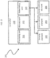
FIG. 3 is a schematic diagram of a controller of the system ofFIG. 2 in accordance with embodiments; -
FIG. 4 is a flow diagram illustrating a method of controlling an MDC in accordance with embodiments; -
FIG. 5 is a flow diagram illustrating a method of detecting an MDC underspeed condition in accordance with embodiments; and -
FIG. 6 is a flow diagram illustrating a further method of controlling an MDC in accordance with embodiments. - These and other advantages and features will become more apparent from the following description taken in conjunction with the drawings.
- As will be described below, thrust bearing failure modes are detected and acted upon by a system that will not shift in position over time and thus will not cease to be fully operational over time. The system involves the use of software-based detection of thrust bearing failures for use with a motor driven compressor (MDC) or another similar device.
-
FIG. 1 is a schematic diagram ofMDC 10 in accordance with embodiments. The MDC 10 includestie rod 12,motor shafts rotor compressor stages thrust runner 20,housing 22,journal bearings thrust bearings drives compressor stages motor shafts journal bearings thrust runner 20 is utilized to prevent axial movement of the rotating components of theMDC 10. Thethrust bearings thrust runner 20 and thehousing 22. Failure modes can occur, for example, due to failures of any of thejournal bearings thrust bearings thrust runner 20 and thehousing 22. This heat is conducted to the surface of thehousing 22 and can lead to above-normal temperatures relative to normal operating temperatures. - With reference to
FIG. 2 , asystem 201 is provided for monitoring and controlling an MDC, such as theMDC 10 ofFIG. 1 . Thesystem 201 includes one or moresensing elements 202, aservo control element 203, atiming element 204 and acontroller 205. The one or moresensing elements 202 may be disposable on at least one of the rotating components of theMDC 10, such as themotor shafts MDC 10, such as thehousing 22. In either case, the one or moresensing elements 202 may be disposed and configured to sense an operational parameter of theMDC 10 and, in accordance with embodiments, this operational parameter may include a rotational speed of the rotational components of theMDC 10 relative to the stationary components of the MDC 10 (e.g., a rotational speed in revolutions per minute (RPM) of themotor shafts servo control element 203 is operably coupled with theMDC 10 and configured to start up, shut down and restart theMDC 10 in accordance with commands or instructions received by theservo control element 203. Thetiming element 204 may be provided as a component of thecontroller 205 or as a standalone component. In either case, thetiming element 204 is configured to time certain events related to the monitoring and controlling of theMDC 10 as will be described below. Thecontroller 205 is coupled to the one ormore sensing elements 202, theservo control element 203 and thetiming element 204. - In accordance with embodiments, the
system 201 may further include a common mode start controller (CMSC) 210. In such cases, theCMSC 210 may be configured to detect an underspeed condition of theMDC 10 by which thecontroller 205 would be able to detect if a restart of theMDC 10 is or is not successful as will be described below. - With continued reference to
FIG. 2 and with additional reference toFIG. 3 , thecontroller 205 includes aprocessing unit 301, amemory unit 302 and anetworking unit 303 by which theprocessing unit 301 is communicative with the one ormore sensing elements 202, theservo control element 203 and thetiming element 204. Theprocessing unit 301 may be provided as a central processing unit (CPU) and is coupled with thememory unit 302 and thenetworking unit 303. Thememory unit 302 has executable instructions stored thereon, which, when executed, cause theprocessing unit 301 to operate as described herein. - For example, when executed, the executable instructions cause the
processing unit 301 to either calculate a predicted minimum speed of theMDC 10 based on current conditions or to access data reflective of the predicted minimum speed in thememory unit 302, to receive signals from the one ormore sensing elements 202 which are reflective of and derived from readings of an actual speed of theMDC 10 that are generated by the one ormore sensing elements 202 and to determine from those signals whether the readings of the one ormore sensing elements 202 are indicative of the actual speed of theMDC 10 falling below the predicted minimum speed (again, the predicted minimum and actual speeds of the MDC are, for example, rotational speeds of a rotating component thereof relative to a stationary component thereof). - In addition, in an event that is can be determined that the actual speed of the
MDC 10 falls or has fallen below the predicted minimum speed, the executable instructions further cause theprocessing unit 301 to determine whether the actual speed of theMDC 10 falls or has fallen below the predicted minimum speed for a first period of time as timed by thetiming element 204. In an event it can be determined that the actual speed of theMDC 10 falls or has fallen below the predicted minimum speed for the first period of time, the executable instructions cause theprocessing unit 301 to in turn cause theservo control element 203 to shut down theMDC 10 for a second period of time as timed by thetiming element 204 following an end of the first period of time and to attempt to restart theMDC 10 following an end of the second period of time. Following the attempted restart, the executable instructions also cause theprocessing unit 301 to determine whether the attempted restart was or was not successful. - In accordance with embodiments, the first period of time may be shorter than the second period of time. In accordance with further embodiments, the first period of time may be about 10 seconds and the second period of time may be about 60 seconds. In accordance with still further embodiments, the determination of whether the attempted restart was or was not successful may be accomplished by the
CMSC 210 being configured to directly sense whether the restart was or was not successful based on theCMSC 210 identifying that an incidence of theMDC 10 exhibiting or experiencing an underspeed condition is in effect and by theprocessing unit 301 communicating with theCMSC 210 to be receptive of a corresponding indication from theCMSC 210 of whether the restart was or was not successful. - In accordance with further embodiments, the executable instructions of the
memory unit 302 may, when executed, cause theprocessing unit 301 to maintain a count of consecutive restarts of theMDC 10 and to cease the determining, the causing and the restarting following a predefined number of consecutive restarts (which may be stored in the memory unit 302), to reset the predefined number of the consecutive restarts in response to a conditional change, such as a flight mission phase change, and to track and store in the memory unit 302 a total number of consecutive and non-consecutive successful restarts for the generation of a report. - With reference to
FIG. 4 , a method of controlling an MDC, such as theMDC 10 ofFIG. 1 is provided and may be executed, for example, by thesystem 201 and thecontroller 205 ofFIGS. 2 and3 . As shown inFIG. 4 , the method includes determining from readings of the one ormore sensing elements 202 whether an actual (rotational or other) speed of theMDC 10 falls below a predicted minimum (rotational or other) speed (block 401) and, if so, determining whether a first period of time as timed by thetiming element 204 has elapsed (block 402). - In an event the actual speed of the
MDC 10 falls or has fallen below the predicted minimum speed and the first period of time has elapsed, the method further includes causing theservo control element 203 to shut down the MDC 10 (block 403), then waiting for a second period of time as timed by the timing element 204 (block 404) and restarting theMDC 10 following an end of the second period of time (block 405). At this point, the method includes detecting if the restart of theMDC 10 is or is not successful (block 406) and tracking and storing a total number of consecutive or non-consecutive restarts for later use in a generated report (block 407). - As noted above, the first period of time may be shorter than the second period of time and, more particularly, the first period of time may be about 10 seconds and the second period of time may be about 60 seconds.
- With reference to
FIG. 5 , a method of executing the detecting of whether the restart of theMDC 10 is or is not successful will now be described. As shown inFIG. 5 , the method includes detecting, at theCMSC 210, that an underspeed condition of theMDC 10 is or is not in effect (block 501), issuing an interrogative signal from theprocessing unit 301 to theCMSC 210 which requests a response signal that is reflective of the detecting (block 502), receiving, at theprocessing unit 301, the response signal from the CMSC 210 (block 503) and determining, at theprocessing unit 301, from the response signal whether the restart is or is not successful based on the content of the response signal (block 504). - With reference to
FIG. 6 , a further method of monitoring and controlling theMDC 10 ofFIG. 1 which is executable by thesystem 201 and thecontroller 205 ofFIGS. 2 and3 will now be described. As shown inFIG. 6 , each successful restart is counted (block 601) and it is determined whether the count has or has not reached a predefined number of consecutive restarts which may, in some cases, be stored in the memory unit 302 (block 602). If the predefined number of consecutive restarts has been reached, the determining, the causing and the restarting are ceased (block 603). Subsequently, the method further includes identifying whether a conditional change, such as a change in a flight mission phase or status, has occurred (block 604) and, if so, resetting the number of the consecutive restarts (block 605) and resuming the determining, the causing and the restarting (block 606). - While the disclosure is provided in detail in connection with only a limited number of embodiments, it should be readily understood that the disclosure is not limited to such disclosed embodiments. Rather, the disclosure can be modified to incorporate any number of variations, alterations, substitutions or equivalent arrangements not heretofore described, but which are commensurate with the spirit and scope of the disclosure. Additionally, while various embodiments of the disclosure have been described, it is to be understood that the exemplary embodiment(s) may include only some of the described exemplary aspects. Accordingly, the disclosure is not to be seen as limited by the foregoing description, but is only limited by the scope of the appended claims.
Claims (15)
- A system (201) for controlling a motor driven compressor (MDC) (10), the system comprising:a sensing element (202);a controller (205) coupled to the sensing element and configured to:determine whether an actual speed of the MDC (10) sensed by the sensing element is below a predicted minimum speed,shut down and then restart the MDC (10), anddetect if the restart of the MDC (10) is successful.
- The system according to claim 1, wherein the actual and predicted minimum speeds are rotational speeds of a rotating element of the MDC (10).
- The system according to claim 1 or 2, wherein the controller (205) is configured to determine whether the actual speed of the MDC (10) is below the predicted minimum speed for a first period of time.
- The system according to claim 3, wherein the controller (205) is further configured to restart the MDC following the shut down after a second period of time.
- The system according to claim 4, wherein the second period of time is longer than the first period of time.
- The system according to any preceding claim, wherein the controller (205) is configured to detect that the restart is successful.
- The system according to claim 6, wherein the controller (205) detects that the restart is successful from detection of an MDC underspeed condition.
- The system according to any preceding claim, wherein the controller (205) is configured to cease the determining and the shutting down and then the restarting following a predefined number of consecutive restarts.
- The system according to claim 8, wherein the predefined number of the consecutive restarts is reset in response to a conditional change.
- The system according to any preceding claim, wherein the controller (205) is configured to track a number of successful restarts.
- A method of controlling a motor driven compressor (MDC) (10), the method comprising:determining whether an actual speed of the MDC (10) falls below a predicted minimum speed for a first period of time;causing the servo control element (203) to shut down the MDC (10) for a second period of time following an end of the first period of time in an event the actual speed of the MDC (10) is below the predicted minimum speed for the first period of time;restarting the MDC (10) following an end of the second period of time; anddetecting if the restart of the MDC (10) is successful.
- The method according to claim 11, wherein the actual and predicted minimum speeds are rotational speeds of a rotating element of the MDC (10).
- The method according to claim 11 or 12, wherein the first period of time is shorter than the second period of time.
- The method according to claim 11, 12 or 13, wherein the detecting comprises detecting an MDC underspeed condition.
- The method according to claim 11, 12, 13 or 14, further comprising ceasing the determining and the shutting down of the MDC (10) and then the restarting following a predefined number of consecutive restarts, wherein the predefined number of the consecutive restarts is reset in response to a conditional change.
Applications Claiming Priority (1)
| Application Number | Priority Date | Filing Date | Title |
|---|---|---|---|
| US201762521738P | 2017-06-19 | 2017-06-19 |
Publications (2)
| Publication Number | Publication Date |
|---|---|
| EP3418578A1 true EP3418578A1 (en) | 2018-12-26 |
| EP3418578B1 EP3418578B1 (en) | 2025-08-20 |
Family
ID=62712916
Family Applications (1)
| Application Number | Title | Priority Date | Filing Date |
|---|---|---|---|
| EP18178630.2A Active EP3418578B1 (en) | 2017-06-19 | 2018-06-19 | Software detection |
Country Status (2)
| Country | Link |
|---|---|
| US (1) | US10830245B2 (en) |
| EP (1) | EP3418578B1 (en) |
Families Citing this family (1)
| Publication number | Priority date | Publication date | Assignee | Title |
|---|---|---|---|---|
| EP3850458A4 (en) * | 2018-09-14 | 2022-06-08 | Delos Living, LLC | Systems and methods for air remediation |
Citations (4)
| Publication number | Priority date | Publication date | Assignee | Title |
|---|---|---|---|---|
| US20050029976A1 (en) * | 2003-01-24 | 2005-02-10 | Terry Robert L. | Brushless and sensorless DC motor control system with locked and stopped rotor detection |
| US8079227B2 (en) * | 2005-12-29 | 2011-12-20 | Johnson Controls Technology Company | Reduced compressor capacity controls |
| EP2412983A2 (en) * | 2010-07-30 | 2012-02-01 | Nuovo Pignone S.p.A. | Method and device for controlling a hot restart of a centrifugal compressor |
| WO2016033481A1 (en) * | 2014-08-29 | 2016-03-03 | Emerson Climate Technologies, Inc. | Variable speed compressor startup control |
Family Cites Families (6)
| Publication number | Priority date | Publication date | Assignee | Title |
|---|---|---|---|---|
| US5125067A (en) * | 1974-06-24 | 1992-06-23 | General Electric Company | Motor controls, refrigeration systems and methods of motor operation and control |
| US4167734A (en) | 1977-02-10 | 1979-09-11 | Watchdog, Inc. | Shaft speed and hot bearing indicating apparatus |
| DE69736960D1 (en) | 1996-09-13 | 2006-12-28 | Timken Co | Bearing with a sensor module |
| DE19710337A1 (en) | 1997-03-13 | 1998-09-24 | Fag Automobiltechnik Ag | Roller bearing incorporating rotation measuring device e.g. for automobile wheel bearing |
| GB9912108D0 (en) | 1999-05-25 | 1999-07-28 | Rolls Royce Plc | Bearing load control |
| US7151349B1 (en) * | 2004-04-08 | 2006-12-19 | Analog Devices, Inc. | Fan speed control |
-
2017
- 2017-08-22 US US15/682,732 patent/US10830245B2/en active Active
-
2018
- 2018-06-19 EP EP18178630.2A patent/EP3418578B1/en active Active
Patent Citations (4)
| Publication number | Priority date | Publication date | Assignee | Title |
|---|---|---|---|---|
| US20050029976A1 (en) * | 2003-01-24 | 2005-02-10 | Terry Robert L. | Brushless and sensorless DC motor control system with locked and stopped rotor detection |
| US8079227B2 (en) * | 2005-12-29 | 2011-12-20 | Johnson Controls Technology Company | Reduced compressor capacity controls |
| EP2412983A2 (en) * | 2010-07-30 | 2012-02-01 | Nuovo Pignone S.p.A. | Method and device for controlling a hot restart of a centrifugal compressor |
| WO2016033481A1 (en) * | 2014-08-29 | 2016-03-03 | Emerson Climate Technologies, Inc. | Variable speed compressor startup control |
Also Published As
| Publication number | Publication date |
|---|---|
| EP3418578B1 (en) | 2025-08-20 |
| US10830245B2 (en) | 2020-11-10 |
| US20180363666A1 (en) | 2018-12-20 |
Similar Documents
| Publication | Publication Date | Title |
|---|---|---|
| RU2564159C2 (en) | Determination of free turbine overspeed by measurements using torque meter | |
| US7030746B2 (en) | Method and system for generating automatic alarms based on trends detected in machine operation | |
| US9404385B2 (en) | Shaft break detection | |
| CN104838148B (en) | Failure prediction in slewing | |
| CN104595220B (en) | The control method of fan, warm-air drier, system of shaking the head and system of shaking the head | |
| CN106574606A (en) | State monitoring system and wind power generation system provided with same | |
| JPWO2010150399A1 (en) | Wind power generator and control method thereof | |
| US6481978B2 (en) | System and method for protecting turbine and compressor during shutdown | |
| JP4874756B2 (en) | Machine Tools | |
| US10590955B2 (en) | Turbo-molecular pump | |
| EP3418578B1 (en) | Software detection | |
| CN115478980A (en) | Wind generating set and its redundant operation method and device, medium | |
| CN111997888B (en) | Fault judgment method, magnetic suspension compressor, air conditioning unit and readable storage medium | |
| CN115143033B (en) | Control method and control device of wind turbine generator set | |
| US11946385B2 (en) | Method for controlling the bending deformation of a turbomachine shaft at rest subjected to the residual heat of operation of the turbomachine | |
| CN114930143B (en) | Condition monitoring devices and wind power generation devices including condition monitoring devices | |
| JP2018040456A (en) | Rotary shaft device and abnormality diagnostic method of bearing on rotary shaft device | |
| CN107110028B (en) | Method for regulating a fuel feed pump | |
| WO2018024963A1 (en) | Method for detecting the blocking of a synchronous motor for a motor vehicle | |
| EP3734251B1 (en) | A method of monitoring an air cycle machine of an aircraft | |
| US20210344296A1 (en) | Method for detecting condensate formation which is imminent or has already taken place on/in electric motors, and method for avoiding corresponding condensate formation and/or for eliminating/reducing condensate on/in electric motors | |
| JPS6130702B2 (en) | ||
| CN119122757A (en) | Abnormality detection method and system for variable pitch limit mechanism of impeller system | |
| US20120057024A1 (en) | System and method for monitoring component wear | |
| JP4721055B2 (en) | Vacuum pump |
Legal Events
| Date | Code | Title | Description |
|---|---|---|---|
| PUAI | Public reference made under article 153(3) epc to a published international application that has entered the european phase |
Free format text: ORIGINAL CODE: 0009012 |
|
| STAA | Information on the status of an ep patent application or granted ep patent |
Free format text: STATUS: THE APPLICATION HAS BEEN PUBLISHED |
|
| AK | Designated contracting states |
Kind code of ref document: A1 Designated state(s): AL AT BE BG CH CY CZ DE DK EE ES FI FR GB GR HR HU IE IS IT LI LT LU LV MC MK MT NL NO PL PT RO RS SE SI SK SM TR |
|
| AX | Request for extension of the european patent |
Extension state: BA ME |
|
| STAA | Information on the status of an ep patent application or granted ep patent |
Free format text: STATUS: REQUEST FOR EXAMINATION WAS MADE |
|
| 17P | Request for examination filed |
Effective date: 20190626 |
|
| RBV | Designated contracting states (corrected) |
Designated state(s): AL AT BE BG CH CY CZ DE DK EE ES FI FR GB GR HR HU IE IS IT LI LT LU LV MC MK MT NL NO PL PT RO RS SE SI SK SM TR |
|
| STAA | Information on the status of an ep patent application or granted ep patent |
Free format text: STATUS: EXAMINATION IS IN PROGRESS |
|
| 17Q | First examination report despatched |
Effective date: 20211015 |
|
| GRAP | Despatch of communication of intention to grant a patent |
Free format text: ORIGINAL CODE: EPIDOSNIGR1 |
|
| STAA | Information on the status of an ep patent application or granted ep patent |
Free format text: STATUS: GRANT OF PATENT IS INTENDED |
|
| INTG | Intention to grant announced |
Effective date: 20250324 |
|
| GRAS | Grant fee paid |
Free format text: ORIGINAL CODE: EPIDOSNIGR3 |
|
| GRAA | (expected) grant |
Free format text: ORIGINAL CODE: 0009210 |
|
| STAA | Information on the status of an ep patent application or granted ep patent |
Free format text: STATUS: THE PATENT HAS BEEN GRANTED |
|
| AK | Designated contracting states |
Kind code of ref document: B1 Designated state(s): AL AT BE BG CH CY CZ DE DK EE ES FI FR GB GR HR HU IE IS IT LI LT LU LV MC MK MT NL NO PL PT RO RS SE SI SK SM TR |
|
| REG | Reference to a national code |
Ref country code: GB Ref legal event code: FG4D |
|
| REG | Reference to a national code |
Ref country code: CH Ref legal event code: EP |
|
| REG | Reference to a national code |
Ref country code: DE Ref legal event code: R096 Ref document number: 602018084703 Country of ref document: DE |
|
| REG | Reference to a national code |
Ref country code: IE Ref legal event code: FG4D |
|
| REG | Reference to a national code |
Ref country code: NL Ref legal event code: MP Effective date: 20250820 |
|
| PG25 | Lapsed in a contracting state [announced via postgrant information from national office to epo] |
Ref country code: IS Free format text: LAPSE BECAUSE OF FAILURE TO SUBMIT A TRANSLATION OF THE DESCRIPTION OR TO PAY THE FEE WITHIN THE PRESCRIBED TIME-LIMIT Effective date: 20251220 |
|
| PG25 | Lapsed in a contracting state [announced via postgrant information from national office to epo] |
Ref country code: NO Free format text: LAPSE BECAUSE OF FAILURE TO SUBMIT A TRANSLATION OF THE DESCRIPTION OR TO PAY THE FEE WITHIN THE PRESCRIBED TIME-LIMIT Effective date: 20251120 |
|
| REG | Reference to a national code |
Ref country code: LT Ref legal event code: MG9D |
|
| PG25 | Lapsed in a contracting state [announced via postgrant information from national office to epo] |
Ref country code: PT Free format text: LAPSE BECAUSE OF FAILURE TO SUBMIT A TRANSLATION OF THE DESCRIPTION OR TO PAY THE FEE WITHIN THE PRESCRIBED TIME-LIMIT Effective date: 20251222 |
|
| PG25 | Lapsed in a contracting state [announced via postgrant information from national office to epo] |
Ref country code: FI Free format text: LAPSE BECAUSE OF FAILURE TO SUBMIT A TRANSLATION OF THE DESCRIPTION OR TO PAY THE FEE WITHIN THE PRESCRIBED TIME-LIMIT Effective date: 20250820 |
|
| PG25 | Lapsed in a contracting state [announced via postgrant information from national office to epo] |
Ref country code: NL Free format text: LAPSE BECAUSE OF FAILURE TO SUBMIT A TRANSLATION OF THE DESCRIPTION OR TO PAY THE FEE WITHIN THE PRESCRIBED TIME-LIMIT Effective date: 20250820 Ref country code: HR Free format text: LAPSE BECAUSE OF FAILURE TO SUBMIT A TRANSLATION OF THE DESCRIPTION OR TO PAY THE FEE WITHIN THE PRESCRIBED TIME-LIMIT Effective date: 20250820 |
|
| PG25 | Lapsed in a contracting state [announced via postgrant information from national office to epo] |
Ref country code: GR Free format text: LAPSE BECAUSE OF FAILURE TO SUBMIT A TRANSLATION OF THE DESCRIPTION OR TO PAY THE FEE WITHIN THE PRESCRIBED TIME-LIMIT Effective date: 20251121 |
|
| PG25 | Lapsed in a contracting state [announced via postgrant information from national office to epo] |
Ref country code: SE Free format text: LAPSE BECAUSE OF FAILURE TO SUBMIT A TRANSLATION OF THE DESCRIPTION OR TO PAY THE FEE WITHIN THE PRESCRIBED TIME-LIMIT Effective date: 20250820 |
|
| PG25 | Lapsed in a contracting state [announced via postgrant information from national office to epo] |
Ref country code: LV Free format text: LAPSE BECAUSE OF FAILURE TO SUBMIT A TRANSLATION OF THE DESCRIPTION OR TO PAY THE FEE WITHIN THE PRESCRIBED TIME-LIMIT Effective date: 20250820 |
|
| PG25 | Lapsed in a contracting state [announced via postgrant information from national office to epo] |
Ref country code: PL Free format text: LAPSE BECAUSE OF FAILURE TO SUBMIT A TRANSLATION OF THE DESCRIPTION OR TO PAY THE FEE WITHIN THE PRESCRIBED TIME-LIMIT Effective date: 20250820 Ref country code: BG Free format text: LAPSE BECAUSE OF FAILURE TO SUBMIT A TRANSLATION OF THE DESCRIPTION OR TO PAY THE FEE WITHIN THE PRESCRIBED TIME-LIMIT Effective date: 20250820 |
|
| PG25 | Lapsed in a contracting state [announced via postgrant information from national office to epo] |
Ref country code: RS Free format text: LAPSE BECAUSE OF FAILURE TO SUBMIT A TRANSLATION OF THE DESCRIPTION OR TO PAY THE FEE WITHIN THE PRESCRIBED TIME-LIMIT Effective date: 20251120 |
|
| PG25 | Lapsed in a contracting state [announced via postgrant information from national office to epo] |
Ref country code: ES Free format text: LAPSE BECAUSE OF FAILURE TO SUBMIT A TRANSLATION OF THE DESCRIPTION OR TO PAY THE FEE WITHIN THE PRESCRIBED TIME-LIMIT Effective date: 20250820 |
|
| REG | Reference to a national code |
Ref country code: AT Ref legal event code: MK05 Ref document number: 1827560 Country of ref document: AT Kind code of ref document: T Effective date: 20250820 |
|
| PG25 | Lapsed in a contracting state [announced via postgrant information from national office to epo] |
Ref country code: SM Free format text: LAPSE BECAUSE OF FAILURE TO SUBMIT A TRANSLATION OF THE DESCRIPTION OR TO PAY THE FEE WITHIN THE PRESCRIBED TIME-LIMIT Effective date: 20250820 |
|
| PG25 | Lapsed in a contracting state [announced via postgrant information from national office to epo] |
Ref country code: DK Free format text: LAPSE BECAUSE OF FAILURE TO SUBMIT A TRANSLATION OF THE DESCRIPTION OR TO PAY THE FEE WITHIN THE PRESCRIBED TIME-LIMIT Effective date: 20250820 |
|
| PG25 | Lapsed in a contracting state [announced via postgrant information from national office to epo] |
Ref country code: AT Free format text: LAPSE BECAUSE OF FAILURE TO SUBMIT A TRANSLATION OF THE DESCRIPTION OR TO PAY THE FEE WITHIN THE PRESCRIBED TIME-LIMIT Effective date: 20250820 |
|
| PG25 | Lapsed in a contracting state [announced via postgrant information from national office to epo] |
Ref country code: IT Free format text: LAPSE BECAUSE OF FAILURE TO SUBMIT A TRANSLATION OF THE DESCRIPTION OR TO PAY THE FEE WITHIN THE PRESCRIBED TIME-LIMIT Effective date: 20250820 |
|
| PG25 | Lapsed in a contracting state [announced via postgrant information from national office to epo] |
Ref country code: CZ Free format text: LAPSE BECAUSE OF FAILURE TO SUBMIT A TRANSLATION OF THE DESCRIPTION OR TO PAY THE FEE WITHIN THE PRESCRIBED TIME-LIMIT Effective date: 20250820 |
|
| PG25 | Lapsed in a contracting state [announced via postgrant information from national office to epo] |
Ref country code: SK Free format text: LAPSE BECAUSE OF FAILURE TO SUBMIT A TRANSLATION OF THE DESCRIPTION OR TO PAY THE FEE WITHIN THE PRESCRIBED TIME-LIMIT Effective date: 20250820 Ref country code: EE Free format text: LAPSE BECAUSE OF FAILURE TO SUBMIT A TRANSLATION OF THE DESCRIPTION OR TO PAY THE FEE WITHIN THE PRESCRIBED TIME-LIMIT Effective date: 20250820 |