EP3418555A1 - Positioning assembly for a wind turbine rotor blade lifting device - Google Patents
Positioning assembly for a wind turbine rotor blade lifting device Download PDFInfo
- Publication number
- EP3418555A1 EP3418555A1 EP17382379.0A EP17382379A EP3418555A1 EP 3418555 A1 EP3418555 A1 EP 3418555A1 EP 17382379 A EP17382379 A EP 17382379A EP 3418555 A1 EP3418555 A1 EP 3418555A1
- Authority
- EP
- European Patent Office
- Prior art keywords
- rotor blade
- lifting device
- hub
- lift system
- cradle
- Prior art date
- Legal status (The legal status is an assumption and is not a legal conclusion. Google has not performed a legal analysis and makes no representation as to the accuracy of the status listed.)
- Pending
Links
Images


Classifications
-
- B—PERFORMING OPERATIONS; TRANSPORTING
- B66—HOISTING; LIFTING; HAULING
- B66C—CRANES; LOAD-ENGAGING ELEMENTS OR DEVICES FOR CRANES, CAPSTANS, WINCHES, OR TACKLES
- B66C13/00—Other constructional features or details
- B66C13/18—Control systems or devices
- B66C13/46—Position indicators for suspended loads or for crane elements
-
- F—MECHANICAL ENGINEERING; LIGHTING; HEATING; WEAPONS; BLASTING
- F03—MACHINES OR ENGINES FOR LIQUIDS; WIND, SPRING, OR WEIGHT MOTORS; PRODUCING MECHANICAL POWER OR A REACTIVE PROPULSIVE THRUST, NOT OTHERWISE PROVIDED FOR
- F03D—WIND MOTORS
- F03D1/00—Wind motors with rotation axis substantially parallel to the air flow entering the rotor
- F03D1/06—Rotors
- F03D1/065—Rotors characterised by their construction elements
- F03D1/0658—Arrangements for fixing wind-engaging parts to a hub
-
- B—PERFORMING OPERATIONS; TRANSPORTING
- B66—HOISTING; LIFTING; HAULING
- B66C—CRANES; LOAD-ENGAGING ELEMENTS OR DEVICES FOR CRANES, CAPSTANS, WINCHES, OR TACKLES
- B66C1/00—Load-engaging elements or devices attached to lifting or lowering gear of cranes or adapted for connection therewith for transmitting lifting forces to articles or groups of articles
- B66C1/10—Load-engaging elements or devices attached to lifting or lowering gear of cranes or adapted for connection therewith for transmitting lifting forces to articles or groups of articles by mechanical means
- B66C1/108—Load-engaging elements or devices attached to lifting or lowering gear of cranes or adapted for connection therewith for transmitting lifting forces to articles or groups of articles by mechanical means for lifting parts of wind turbines
-
- B—PERFORMING OPERATIONS; TRANSPORTING
- B66—HOISTING; LIFTING; HAULING
- B66C—CRANES; LOAD-ENGAGING ELEMENTS OR DEVICES FOR CRANES, CAPSTANS, WINCHES, OR TACKLES
- B66C13/00—Other constructional features or details
- B66C13/16—Applications of indicating, registering, or weighing devices
-
- B—PERFORMING OPERATIONS; TRANSPORTING
- B66—HOISTING; LIFTING; HAULING
- B66C—CRANES; LOAD-ENGAGING ELEMENTS OR DEVICES FOR CRANES, CAPSTANS, WINCHES, OR TACKLES
- B66C13/00—Other constructional features or details
- B66C13/18—Control systems or devices
-
- F—MECHANICAL ENGINEERING; LIGHTING; HEATING; WEAPONS; BLASTING
- F03—MACHINES OR ENGINES FOR LIQUIDS; WIND, SPRING, OR WEIGHT MOTORS; PRODUCING MECHANICAL POWER OR A REACTIVE PROPULSIVE THRUST, NOT OTHERWISE PROVIDED FOR
- F03D—WIND MOTORS
- F03D13/00—Assembly, mounting or commissioning of wind motors; Arrangements specially adapted for transporting wind motor components
- F03D13/10—Assembly of wind motors; Arrangements for erecting wind motors
-
- F—MECHANICAL ENGINEERING; LIGHTING; HEATING; WEAPONS; BLASTING
- F05—INDEXING SCHEMES RELATING TO ENGINES OR PUMPS IN VARIOUS SUBCLASSES OF CLASSES F01-F04
- F05B—INDEXING SCHEME RELATING TO WIND, SPRING, WEIGHT, INERTIA OR LIKE MOTORS, TO MACHINES OR ENGINES FOR LIQUIDS COVERED BY SUBCLASSES F03B, F03D AND F03G
- F05B2230/00—Manufacture
- F05B2230/60—Assembly methods
- F05B2230/604—Assembly methods using positioning or alignment devices for aligning or centering, e.g. pins
-
- F—MECHANICAL ENGINEERING; LIGHTING; HEATING; WEAPONS; BLASTING
- F05—INDEXING SCHEMES RELATING TO ENGINES OR PUMPS IN VARIOUS SUBCLASSES OF CLASSES F01-F04
- F05B—INDEXING SCHEME RELATING TO WIND, SPRING, WEIGHT, INERTIA OR LIKE MOTORS, TO MACHINES OR ENGINES FOR LIQUIDS COVERED BY SUBCLASSES F03B, F03D AND F03G
- F05B2230/00—Manufacture
- F05B2230/60—Assembly methods
- F05B2230/61—Assembly methods using auxiliary equipment for lifting or holding
-
- F—MECHANICAL ENGINEERING; LIGHTING; HEATING; WEAPONS; BLASTING
- F05—INDEXING SCHEMES RELATING TO ENGINES OR PUMPS IN VARIOUS SUBCLASSES OF CLASSES F01-F04
- F05B—INDEXING SCHEME RELATING TO WIND, SPRING, WEIGHT, INERTIA OR LIKE MOTORS, TO MACHINES OR ENGINES FOR LIQUIDS COVERED BY SUBCLASSES F03B, F03D AND F03G
- F05B2230/00—Manufacture
- F05B2230/70—Disassembly methods
-
- Y—GENERAL TAGGING OF NEW TECHNOLOGICAL DEVELOPMENTS; GENERAL TAGGING OF CROSS-SECTIONAL TECHNOLOGIES SPANNING OVER SEVERAL SECTIONS OF THE IPC; TECHNICAL SUBJECTS COVERED BY FORMER USPC CROSS-REFERENCE ART COLLECTIONS [XRACs] AND DIGESTS
- Y02—TECHNOLOGIES OR APPLICATIONS FOR MITIGATION OR ADAPTATION AGAINST CLIMATE CHANGE
- Y02E—REDUCTION OF GREENHOUSE GAS [GHG] EMISSIONS, RELATED TO ENERGY GENERATION, TRANSMISSION OR DISTRIBUTION
- Y02E10/00—Energy generation through renewable energy sources
- Y02E10/70—Wind energy
- Y02E10/72—Wind turbines with rotation axis in wind direction
-
- Y—GENERAL TAGGING OF NEW TECHNOLOGICAL DEVELOPMENTS; GENERAL TAGGING OF CROSS-SECTIONAL TECHNOLOGIES SPANNING OVER SEVERAL SECTIONS OF THE IPC; TECHNICAL SUBJECTS COVERED BY FORMER USPC CROSS-REFERENCE ART COLLECTIONS [XRACs] AND DIGESTS
- Y02—TECHNOLOGIES OR APPLICATIONS FOR MITIGATION OR ADAPTATION AGAINST CLIMATE CHANGE
- Y02P—CLIMATE CHANGE MITIGATION TECHNOLOGIES IN THE PRODUCTION OR PROCESSING OF GOODS
- Y02P70/00—Climate change mitigation technologies in the production process for final industrial or consumer products
- Y02P70/50—Manufacturing or production processes characterised by the final manufactured product
Definitions
- the present disclosure relates in general to wind turbines, and more particularly to a positioning assembly for lifting devices for wind turbine rotor blades.
- a modem wind turbine typically includes a tower, a generator, a gearbox, a nacelle, and one or more rotor blades.
- the rotor blades capture kinetic energy of wind using known airfoil principles.
- the rotor blades transmit the kinetic energy in the form of rotational energy so as to turn a shaft coupling the rotor blades to a gearbox, or if a gearbox is not used, directly to the generator.
- the generator then converts the mechanical energy to electrical energy that may be deployed to a utility grid.
- the typical construction of a wind turbine involves erecting the tower and then connecting various other components to the erected tower.
- the rotor blades may be lifted to an appropriate height and connected to the tower after installation of the tower onto a foundation.
- each of the rotor blades is connected to a hub before lifting, and the connected rotor blades and hub are then lifted and connected to the tower as a unit.
- Trends towards taller towers and larger rotor diameters can limit and/or preclude lifting such units to the tower due to size and/or cost. More specifically, as the rotor diameter and/or mass and hub height increases, there are few (if any) cranes that can lift such structures. Further, the sail area can become so large, that the available wind window to conduct such lifts approaches zero, i.e. the cranes cannot lift the rotor without tipping over.
- the art is continuously seeking new and improved lifting devices and accessories thereof for wind turbine rotor blades.
- the present disclosure is directed to a positioning assembly for lifting devices for wind turbine rotor blades that assists in installing or removing and lowering the rotor blade to and from the hub.
- the present disclosure is directed to a lift system for a rotor blade of a wind turbine.
- the lift system includes a lifting device having at least one cradle.
- the cradle has a profile that corresponds to at least one of the exterior surfaces of the rotor blade so as to support at least a portion of the rotor blade.
- the lift system includes a positioning assembly having at least one distance sensor mounted to the hub and at least one visual sensor mounted to the lifting device.
- the distance sensor is configured to identify a distance from the hub to the lifting device and the visual sensor is configured to identify a position of the rotor blade in the cradle.
- the distance sensor(s) may include an emitter and a receiver. More specifically, in such embodiments, the emitter may include an infrared light and the receiver may include a camera. In another embodiment, the distance sensor(s) may be mounted to a pitch bearing of the wind turbine.
- the positioning assembly may further include a positioning target secured to the lifting device.
- the emitter is configured to emit signals to the positioning target
- the receiver is configured to receive signals from the positioning target to identify the distance from the hub to the lifting device.
- the positioning target may be secured to the lifting device via one or more magnets.
- the distance sensor(s) may have Wi-Fi capabilities.
- the visual sensor(s) may include, at least, a first set of sensors having a first visual sensor and a second visual sensor.
- the first and second visual sensors may include cameras.
- the lifting device may include a root cradle for supporting the root of the rotor blade and a tip cradle for supporting the tip of the rotor blade.
- the first and second visual sensors may be mounted to the root cradle. More specifically, in certain embodiments, the first visual sensor may be mounted to a lower support member of the root cradle so as to view a span-wise direction of the rotor blade and the second visual sensor may be mounted to an opposing upper support member of the root cradle so as to view a chord-wise direction of the rotor blade.
- the visual sensor(s) may also include a second set of visual sensors mounted to the tip cradle.
- the lifting device may further include a structural frame body for connecting and supporting the root cradle and the tip cradle as well as one or more safety features configured to restrict movement of the rotor blade.
- the present disclosure is directed to a method for lowering a rotor blade from a hub mounted atop a tower of a wind turbine.
- the method includes mounting at least one distance sensor of a positioning assembly to the hub.
- the method also includes lifting, via a crane, a lifting device from a ground location to the hub.
- the lifting device may include root and tip cradles for supporting the rotor blade and at least one visual sensor mounted thereto.
- the method may also include positioning the lifting device with respect to the hub via the distance sensor.
- Another step includes mounting the lifting device to the rotor blade.
- the method includes positioning the rotor blade into the root and tip cradles of the lifting device using the at least one visual sensor.
- Still additional steps include detaching the rotor blade from the hub and lowering, via the crane, the rotor blade from the hub to the ground location. It should also be understood that the method may further include any of the additional features and/or steps as described herein.
- the method may also include securing a positioning target to the lifting device, emitting, via an emitter of the at least one distance sensor, one or more signals to the positioning target, and receiving, via a receive of the at least one distance sensor, the one or more signals from the positioning target to identify the distance between the lifting device and the hub.
- the present disclosure is directed to a lift system for a wind turbine rotor blade.
- the lift system includes a lifting device having at least one cradle.
- the cradle has a profile that corresponds to at least one of the exterior surfaces of the rotor blade so as to support at least a portion of the rotor blade.
- the lift system includes a positioning assembly having at least one distance sensor mounted to the hub and at least one visual sensor mounted to the lifting device.
- the distance sensor is configured to identify a distance from the hub to the lifting device and the visual sensor is configured to identify a position of the rotor blade in the cradle.
- the positioning assembly of the present disclosure is configured to identify how far is the lifting device is from the hub.
- the visual sensor(s) mounted to the lifting device check the rotor blades position within the lifting device.
- Such data can be viewed in real-time by an operator, e.g. from a portable device, so as to assist with installing or removing the rotor blade from the hub.
- FIG. 1 illustrates a wind turbine 10 of conventional construction.
- the wind turbine 10 includes a tower 12 with a nacelle 14 mounted thereon.
- a plurality of rotor blades 16 are mounted to a rotor hub 18, such as via the roots (discussed below) of the rotor blades 16 via a pitch bearing 63 ( FIG. 8 ), which is in turn connected to a main flange that turns a main rotor shaft (not shown).
- the wind turbine power generation and control components are typically housed within the nacelle 14 and/or the tower 12.
- the view of FIG. 1 is provided for illustrative purposes only to place the present invention in an exemplary field of use. It should be appreciated that the invention is not limited to any particular type of wind turbine configuration.
- the rotor blade 16 includes exterior surfaces defining a pressure side 22 and a suction side 24 extending between a leading edge 26 and a trailing edge 28, and may extend from a blade tip 32 to a blade root 34.
- the exterior surfaces may be generally aerodynamic surfaces having generally aerodynamic contours, as is generally known in the art.
- the rotor blade 16 may include a plurality of individual blade segments aligned in an end-to-end order from the blade tip 32 to the blade root 34.
- Each of the individual blade segments may be uniquely configured such that the plurality of blade segments define a complete rotor blade 16 having a designed aerodynamic profile, length, and other desired characteristics.
- each of the blade segments may have an aerodynamic profile that corresponds to the aerodynamic profile of adjacent blade segments.
- the aerodynamic profiles of the blade segments may form a continuous aerodynamic profile of the rotor blade 16.
- the rotor blade 16 may be formed as a singular, unitary blade having the designed aerodynamic profile, length, and other desired characteristics.
- the rotor blade 16 may, in exemplary embodiments, be curved. Curving of the rotor blade 16 may entail bending the rotor blade 16 in a generally flap-wise direction and/or in a generally edge-wise direction.
- the flap-wise direction may generally be construed as the direction (or the opposite direction) in which the aerodynamic lift acts on the rotor blade 16.
- the edge-wise direction is generally perpendicular to the flap-wise direction.
- Flap-wise curvature of the rotor blade 16 is also known as pre-bend, while edgewise curvature is also known as sweep.
- a curved rotor blade 16 may be pre-bent and/or swept. Curving may enable the rotor blade 16 to better withstand flapwise and edgewise loads during operation of the wind turbine 10, and may further provide clearance for the rotor blade 16 from the tower 12 during operation of the wind turbine 10.
- the rotor blade 16 may further define chord 42 and a span 44. Further, as shown in FIG. 2 , the chord 42 may vary throughout the span 44 of the rotor blade 16. Thus, a local chord may be defined for the rotor blade 16 at any point on the rotor blade 16 along the span 44.
- the exterior surfaces, as discussed above, may extend in the generally span-wise direction between the tip 32 and root 34.
- the lift system 50 includes a lifting device 52 configured to support at least a portion of one of the rotor blades 16. More specifically, as shown, the lifting device 52 includes at least one cradle 54, 56 and a positioning assembly 60 configured with the lifting device 52, which is described in more detail below. Further, as shown generally in FIGS. 3-6 , the lifting device 52 includes a root cradle 54 and a tip cradle 56 for supporting portions of the blade 16 near the blade root 34 and the blade tip 32, respectively.
- each of the cradles 54, 56 generally has a profile that corresponds to at least one of the exterior surfaces of the rotor blade 16 so as to support at least a portion of the rotor blade 16.
- the root cradle 54 has a profile that generally corresponds to the blade root 34 of the rotor blade 16
- the tip cradle 56 has a profile that generally corresponds to the blade tip 32 of the rotor blade 16.
- the lifting device 52 may include a structural frame body 55 for connecting and supporting the root cradle 54 and the tip cradle 56. More specifically, as shown, the structural frame body 55 may include one or more cradle support members 57 configured to support each of the root and tip cradles 54, 56, respectively. Thus, as shown, the root and tip cradles 54, 56 may be mounted to respective ends of the structural frame body 55. Further, the cradle supports 57 may be joined or coupled together via a main support 59 or beam. Thus, in additional embodiments, the lift system 50 may also include a crane 92 ( FIG. 8 ) and a crane cable or sling 58 ( FIGS. 3, 4 , and 8 ).
- the crane cable or sling 58 may be connected to the crane 92 and the structural frame body 55 (i.e. at a central location along the main support 59) for lifting and/or lowering the rotor blade 16 between the hub 18 and the tower 12. More specifically, as shown, the crane cable or sling 58 may include a synthetic fabric sling and a point attachment at the center of the structural frame body 55 so as to provide stability to the lifting device 52 during lifting and/or lowering.
- the crane 92 as described herein may be any suitable machine for generally lifting equipment and/or materials, such as a mobile crane, a floating crane, an aerial crane, or a fixed crane (such as a tower crane), as is generally known in the art.
- the crane cable or sling 58 may be connected to the crane 92, and the crane 92 may control movement of the crane cable or sling 58, as is generally known in the art.
- the lift system 50 may also include one or more safety features 76, 78.
- the safety features may include a first safety feature 76 configured with the root cradle 54 and a second safety feature 78 configured with the tip cradle 56.
- the first and second safety features 76, 78 may include a non-contact gate having an optionally pivotable arm 84 with an air-foil shaped attachment 86 at a distal end thereof.
- the first and second safety features 76, 78 are configured to prevent the rotor blade 16 from dislodging from the cradles 54, 56.
- the geometry of the airfoil-shaped attachment 86 is configured to restrict movement of the blade root 34 and the blade tip 32 of the rotor blade 16.
- the lift system 50 also includes a positioning assembly 60 having at least one distance sensor 62 mounted to the hub 18 and at least one visual sensor 72, 74 mounted to the lifting device 52.
- the distance sensor 62 is configured to identify a distance 68 from the hub 18 to the lifting device 52 and the visual sensor(s) 72, 74 is configured to identify a position of the rotor blade 16 in the cradle(s) 54, 56.
- the distance 68 and/or the position of the rotor blade 16 can be viewed in real-time by an operator, e.g. from a portable device, so as to assist with installing or removing the rotor blade 16 from the hub 18.
- the distance sensor(s) 62 may include an emitter 64 and a receiver 66. More specifically, in such embodiments, the emitter 64 may include an infrared light 65 and the receiver 66 may include a camera 67. In another embodiment, the distance sensor(s) 62 may be mounted to one of the pitch bearings 63 of the wind turbine 10. In additional embodiments, the distance sensor(s) 62 may have Wi-Fi capabilities, e.g. via a Wi-Fi antenna 90.
- the positioning assembly 60 may further include a positioning target 87 secured to the lifting device 52.
- the positioning target 87 may be secured to the lifting device 52 via one or more magnets 88.
- the emitter 64 is configured to emit signals towards the positioning target 87
- the receiver 66 is configured to receive signals from the positioning target 87 so to identify the distance 68 from the hub 18 to the lifting device 52.
- the visual sensor(s) 72, 74 may include, at least, a first set of sensors having a first visual sensor 72 and a second visual sensor 74.
- the first and second visual sensors 72, 74 may include cameras.
- the first and second visual sensors 72, 74 may be mounted to the root cradle 54.
- the visual sensor(s) 72, 74 may also include a second set of visual sensors mounted to the tip cradle 56. More specifically, as shown in FIG.
- the first visual sensor 72 may be mounted to a lower support member 71 of the root cradle 54 so as to view a span-wise direction of the rotor blade 16
- the second visual sensor 74 may be mounted to an opposing upper support member 73 of the root cradle 54 so as to view a chord-wise direction of the rotor blade 16.
- the visual sensors 72, 74 may further be mounted to any suitable location on the structural frame body 55 of the lifting device 52 (e.g. any of the support members 57).
- the positioning assembly 60 may also include a controller 70 configured to receive one or more signals from the various sensors (e.g. sensors 62, 72, 74) described herein.
- the controller 70 as described herein may be an independent controller separate from the turbine controller or may be incorporated into the turbine controller of the wind turbine 10 (not shown).
- the controller 70 my include any suitable control system including but not limited to a handheld remote, a personal digital assistant, cellular telephone, a separate pendant controller, or a computer.
- the controller 70 may include suitable processing apparatus and software for operating the positioning assembly 60 as desired or required.
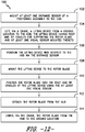
- FIG. 12 illustrates a flow diagram of one embodiment of a method 100 for lowering a rotor blade 16 from a hub 18 mounted atop a tower 12 of a wind turbine 10.
- the method 100 includes mounting at least one distance sensor 62 of the positioning assembly 60 to the hub 18.
- the method 100 includes lifting, via a crane 92, the lifting device 52 from a ground location to the hub 18.
- the method 100 includes positioning the lifting device 52 with respect to the hub 18 via the distance sensor 60.
- the method 100 includes mounting the lifting device 52 to the rotor blade 16. As shown at 110, the method 100 includes positioning the rotor blade 16 into the root and tip cradles 54, 56 of the lifting device 52 using the at least one visual sensor 72, 74. As shown at 112, the method 100 includes detaching the rotor blade 16 from the hub 18. As shown at 114, the method 100 includes lowering, via the crane 92, the rotor blade 16 from the hub 18 to the ground location.
Landscapes
- Engineering & Computer Science (AREA)
- Mechanical Engineering (AREA)
- Life Sciences & Earth Sciences (AREA)
- Sustainable Development (AREA)
- Sustainable Energy (AREA)
- Chemical & Material Sciences (AREA)
- Combustion & Propulsion (AREA)
- General Engineering & Computer Science (AREA)
- Automation & Control Theory (AREA)
- Wind Motors (AREA)
Abstract
Description
- The present disclosure relates in general to wind turbines, and more particularly to a positioning assembly for lifting devices for wind turbine rotor blades.
- Wind power is considered one of the cleanest, most environmentally friendly energy sources presently available, and wind turbines have gained increased attention in this regard. A modem wind turbine typically includes a tower, a generator, a gearbox, a nacelle, and one or more rotor blades. The rotor blades capture kinetic energy of wind using known airfoil principles. The rotor blades transmit the kinetic energy in the form of rotational energy so as to turn a shaft coupling the rotor blades to a gearbox, or if a gearbox is not used, directly to the generator. The generator then converts the mechanical energy to electrical energy that may be deployed to a utility grid.
- The typical construction of a wind turbine involves erecting the tower and then connecting various other components to the erected tower. For example, the rotor blades may be lifted to an appropriate height and connected to the tower after installation of the tower onto a foundation. In some cases, each of the rotor blades is connected to a hub before lifting, and the connected rotor blades and hub are then lifted and connected to the tower as a unit. Trends towards taller towers and larger rotor diameters, however, can limit and/or preclude lifting such units to the tower due to size and/or cost. More specifically, as the rotor diameter and/or mass and hub height increases, there are few (if any) cranes that can lift such structures. Further, the sail area can become so large, that the available wind window to conduct such lifts approaches zero, i.e. the cranes cannot lift the rotor without tipping over.
- Thus, current systems and methods for lifting the rotor blades involve the use of a cradle, sling, or clamping-type blade lifting device that supports an individual rotor blade therein and is lifted to the tower using a crane. As such, each of the rotor blades is then connected to the tower, and the crane is then disconnected therefrom. To overcome safety risks, many modem lifting tools also incorporate positive clamping means to prevent blade movement or loss of control during the lifting process.
- For such lifting device, it is important that the rotor blade be properly positioned therein such that when the rotor blade is lifted uptower or lowered to the ground, the blade is in the correct orientation with respect to the hub so that it can be easily attached thereto, e.g. via a pitch bearing, or detached therefrom. Thus, it would also be advantageous to know the location of the lifting device with respect to the hub.
- In view of the aforementioned, the art is continuously seeking new and improved lifting devices and accessories thereof for wind turbine rotor blades. As such, the present disclosure is directed to a positioning assembly for lifting devices for wind turbine rotor blades that assists in installing or removing and lowering the rotor blade to and from the hub.
- Aspects and advantages of the invention will be set forth in part in the following description, or may be obvious from the description, or may be learned through practice of the invention.
- In one aspect, the present disclosure is directed to a lift system for a rotor blade of a wind turbine. The lift system includes a lifting device having at least one cradle. The cradle has a profile that corresponds to at least one of the exterior surfaces of the rotor blade so as to support at least a portion of the rotor blade. Further, the lift system includes a positioning assembly having at least one distance sensor mounted to the hub and at least one visual sensor mounted to the lifting device. Thus, the distance sensor is configured to identify a distance from the hub to the lifting device and the visual sensor is configured to identify a position of the rotor blade in the cradle.
- In one embodiment, the distance sensor(s) may include an emitter and a receiver. More specifically, in such embodiments, the emitter may include an infrared light and the receiver may include a camera. In another embodiment, the distance sensor(s) may be mounted to a pitch bearing of the wind turbine.
- In further embodiments, the positioning assembly may further include a positioning target secured to the lifting device. As such, the emitter is configured to emit signals to the positioning target, whereas the receiver is configured to receive signals from the positioning target to identify the distance from the hub to the lifting device. In several embodiments, the positioning target may be secured to the lifting device via one or more magnets.
- In additional embodiments, the distance sensor(s) may have Wi-Fi capabilities.
- In yet another embodiment, the visual sensor(s) may include, at least, a first set of sensors having a first visual sensor and a second visual sensor. In such embodiments, the first and second visual sensors may include cameras.
- In further embodiments, the lifting device may include a root cradle for supporting the root of the rotor blade and a tip cradle for supporting the tip of the rotor blade. As such, in one embodiment, the first and second visual sensors may be mounted to the root cradle. More specifically, in certain embodiments, the first visual sensor may be mounted to a lower support member of the root cradle so as to view a span-wise direction of the rotor blade and the second visual sensor may be mounted to an opposing upper support member of the root cradle so as to view a chord-wise direction of the rotor blade.
- In still further embodiments, the visual sensor(s) may also include a second set of visual sensors mounted to the tip cradle.
- In particular embodiments, the lifting device may further include a structural frame body for connecting and supporting the root cradle and the tip cradle as well as one or more safety features configured to restrict movement of the rotor blade.
- In another aspect, the present disclosure is directed to a method for lowering a rotor blade from a hub mounted atop a tower of a wind turbine. The method includes mounting at least one distance sensor of a positioning assembly to the hub. The method also includes lifting, via a crane, a lifting device from a ground location to the hub. Further, as mentioned, the lifting device may include root and tip cradles for supporting the rotor blade and at least one visual sensor mounted thereto. As such, the method may also include positioning the lifting device with respect to the hub via the distance sensor. Another step includes mounting the lifting device to the rotor blade. In addition, the method includes positioning the rotor blade into the root and tip cradles of the lifting device using the at least one visual sensor. Still additional steps include detaching the rotor blade from the hub and lowering, via the crane, the rotor blade from the hub to the ground location. It should also be understood that the method may further include any of the additional features and/or steps as described herein.
- In addition, the method may also include securing a positioning target to the lifting device, emitting, via an emitter of the at least one distance sensor, one or more signals to the positioning target, and receiving, via a receive of the at least one distance sensor, the one or more signals from the positioning target to identify the distance between the lifting device and the hub.
- These and other features, aspects and advantages of the present invention will become better understood with reference to the following description and appended claims. The accompanying drawings, which are incorporated in and constitute a part of this specification, illustrate embodiments of the invention and, together with the description, serve to explain the principles of the invention.
- A full and enabling disclosure of the present invention, including the best mode thereof, directed to one of ordinary skill in the art, is set forth in the specification, which makes reference to the appended figures, in which:
-
FIG. 1 illustrates a perspective view of one embodiment of a wind turbine according to the present disclosure; -
FIG. 2 illustrates a side view of one embodiment of a rotor blade according to the present disclosure; -
FIG. 3 illustrates a perspective view of one embodiment of a lift system according to the present disclosure; -
FIG. 4 illustrates a perspective view of one embodiment of a lifting device according to the present disclosure; -
FIG. 5 illustrates a perspective view of another embodiment of a lift system according to the present disclosure, particularly illustrating the root and tip cradles thereof; -
FIG. 6 illustrates a perspective view of yet another embodiment of a lift system according to the present disclosure, particularly illustrating various safety features thereof; -
FIG. 7 illustrates a detailed, side view of the various safety features of the lift system ofFIG. 6 ; -
FIG. 8 illustrates a perspective view of one embodiment of a wind turbine during installation thereof, particularly illustrating a rotor blade of the wind turbine being lifted uptower via a lift system and the lift system being positioned via a positioning assembly thereof according to the present disclosure; -
FIG. 9 illustrates a partial, perspective view of one embodiment of a hub of a wind turbine according to the present disclosure, particularly illustrating a distance sensor of the positioning assembly mounted to a pitch bearing of the hub; -
FIG. 10 illustrates a detailed, perspective view of one embodiment of the distance sensor of the positioning assembly ofFIG. 9 ; -
FIG. 11 illustrates a perspective view of one embodiment of the lift system having at least a portion of a positioning assembly mounted to a lifting device thereof according to the present disclosure, particularly illustrating the visual sensors and positioning target of the positioning assembly; and -
FIG. 12 illustrates a flow diagram of one embodiment of a method for lowering a rotor blade from a hub mounted atop a tower of a wind turbine according to the present disclosure. - Reference now will be made in detail to embodiments of the invention, one or more examples of which are illustrated in the drawings. Each example is provided by way of explanation of the invention, not limitation of the invention. In fact, it will be apparent to those skilled in the art that various modifications and variations can be made in the present invention without departing from the scope or spirit of the invention. For instance, features illustrated or described as part of one embodiment can be used with another embodiment to yield a still further embodiment. Thus, it is intended that the present invention covers such modifications and variations as come within the scope of the appended claims and their equivalents.
- Generally, the present disclosure is directed to a lift system for a wind turbine rotor blade. More specifically, the lift system includes a lifting device having at least one cradle. The cradle has a profile that corresponds to at least one of the exterior surfaces of the rotor blade so as to support at least a portion of the rotor blade. Further, the lift system includes a positioning assembly having at least one distance sensor mounted to the hub and at least one visual sensor mounted to the lifting device. Thus, the distance sensor is configured to identify a distance from the hub to the lifting device and the visual sensor is configured to identify a position of the rotor blade in the cradle.
- The present disclosure provides many advantages not present in the prior art. For example, the positioning assembly of the present disclosure is configured to identify how far is the lifting device is from the hub. In parallel, the visual sensor(s) mounted to the lifting device check the rotor blades position within the lifting device. Such data can be viewed in real-time by an operator, e.g. from a portable device, so as to assist with installing or removing the rotor blade from the hub.
- Referring now to the drawings,
FIG. 1 illustrates awind turbine 10 of conventional construction. Thewind turbine 10 includes atower 12 with anacelle 14 mounted thereon. A plurality ofrotor blades 16 are mounted to arotor hub 18, such as via the roots (discussed below) of therotor blades 16 via a pitch bearing 63 (FIG. 8 ), which is in turn connected to a main flange that turns a main rotor shaft (not shown). The wind turbine power generation and control components are typically housed within thenacelle 14 and/or thetower 12. The view ofFIG. 1 is provided for illustrative purposes only to place the present invention in an exemplary field of use. It should be appreciated that the invention is not limited to any particular type of wind turbine configuration. - Referring to
FIG. 2 , a perspective view of one of rotor blade 16s according to the present disclosure is illustrated. As shown, therotor blade 16 includes exterior surfaces defining apressure side 22 and asuction side 24 extending between aleading edge 26 and a trailingedge 28, and may extend from ablade tip 32 to ablade root 34. The exterior surfaces may be generally aerodynamic surfaces having generally aerodynamic contours, as is generally known in the art. In some embodiments, therotor blade 16 may include a plurality of individual blade segments aligned in an end-to-end order from theblade tip 32 to theblade root 34. Each of the individual blade segments may be uniquely configured such that the plurality of blade segments define acomplete rotor blade 16 having a designed aerodynamic profile, length, and other desired characteristics. For example, each of the blade segments may have an aerodynamic profile that corresponds to the aerodynamic profile of adjacent blade segments. Thus, the aerodynamic profiles of the blade segments may form a continuous aerodynamic profile of therotor blade 16. Alternatively, therotor blade 16 may be formed as a singular, unitary blade having the designed aerodynamic profile, length, and other desired characteristics. - The
rotor blade 16 may, in exemplary embodiments, be curved. Curving of therotor blade 16 may entail bending therotor blade 16 in a generally flap-wise direction and/or in a generally edge-wise direction. The flap-wise direction may generally be construed as the direction (or the opposite direction) in which the aerodynamic lift acts on therotor blade 16. The edge-wise direction is generally perpendicular to the flap-wise direction. Flap-wise curvature of therotor blade 16 is also known as pre-bend, while edgewise curvature is also known as sweep. Thus, acurved rotor blade 16 may be pre-bent and/or swept. Curving may enable therotor blade 16 to better withstand flapwise and edgewise loads during operation of thewind turbine 10, and may further provide clearance for therotor blade 16 from thetower 12 during operation of thewind turbine 10. - Still referring to
FIG. 2 , therotor blade 16 may further definechord 42 and aspan 44. Further, as shown inFIG. 2 , thechord 42 may vary throughout thespan 44 of therotor blade 16. Thus, a local chord may be defined for therotor blade 16 at any point on therotor blade 16 along thespan 44. The exterior surfaces, as discussed above, may extend in the generally span-wise direction between thetip 32 androot 34. - Referring now to
FIGS. 3 through 11 , various components of alift system 50 for lifting arotor blade 16 of awind turbine 10 uptower according to the present disclosure are illustrated. As shown inFIGS. 3 and 4 , thelift system 50 includes alifting device 52 configured to support at least a portion of one of therotor blades 16. More specifically, as shown, the liftingdevice 52 includes at least onecradle positioning assembly 60 configured with the liftingdevice 52, which is described in more detail below. Further, as shown generally inFIGS. 3-6 , the liftingdevice 52 includes aroot cradle 54 and atip cradle 56 for supporting portions of theblade 16 near theblade root 34 and theblade tip 32, respectively. Further, in certain embodiments, a portion of each of thecradles rotor blade 16 so as to support at least a portion of therotor blade 16. For example, as shown inFIGS. 3 and5 , theroot cradle 54 has a profile that generally corresponds to theblade root 34 of therotor blade 16, whereas thetip cradle 56 has a profile that generally corresponds to theblade tip 32 of therotor blade 16. - In addition, as shown in
FIGS. 3-5 , the liftingdevice 52 may include astructural frame body 55 for connecting and supporting theroot cradle 54 and thetip cradle 56. More specifically, as shown, thestructural frame body 55 may include one or morecradle support members 57 configured to support each of the root and tip cradles 54, 56, respectively. Thus, as shown, the root and tip cradles 54, 56 may be mounted to respective ends of thestructural frame body 55. Further, the cradle supports 57 may be joined or coupled together via amain support 59 or beam. Thus, in additional embodiments, thelift system 50 may also include a crane 92 (FIG. 8 ) and a crane cable or sling 58 (FIGS. 3, 4 , and8 ). In such embodiments, the crane cable orsling 58 may be connected to thecrane 92 and the structural frame body 55 (i.e. at a central location along the main support 59) for lifting and/or lowering therotor blade 16 between thehub 18 and thetower 12. More specifically, as shown, the crane cable orsling 58 may include a synthetic fabric sling and a point attachment at the center of thestructural frame body 55 so as to provide stability to thelifting device 52 during lifting and/or lowering. - The
crane 92 as described herein may be any suitable machine for generally lifting equipment and/or materials, such as a mobile crane, a floating crane, an aerial crane, or a fixed crane (such as a tower crane), as is generally known in the art. Further, the crane cable orsling 58 may be connected to thecrane 92, and thecrane 92 may control movement of the crane cable orsling 58, as is generally known in the art. - Referring now to
FIGS. 6 and 7 , thelift system 50 may also include one or more safety features 76, 78. For example, as shown, the safety features may include afirst safety feature 76 configured with theroot cradle 54 and asecond safety feature 78 configured with thetip cradle 56. More specifically, as shown, the first and second safety features 76, 78 may include a non-contact gate having an optionallypivotable arm 84 with an air-foil shapedattachment 86 at a distal end thereof. As such, the first and second safety features 76, 78 are configured to prevent therotor blade 16 from dislodging from thecradles attachment 86 is configured to restrict movement of theblade root 34 and theblade tip 32 of therotor blade 16. - Referring generally to
FIGS. 3-6 and8-11 , thelift system 50 also includes apositioning assembly 60 having at least onedistance sensor 62 mounted to thehub 18 and at least onevisual sensor lifting device 52. Thus, as shown inFIG. 8 , thedistance sensor 62 is configured to identify adistance 68 from thehub 18 to thelifting device 52 and the visual sensor(s) 72, 74 is configured to identify a position of therotor blade 16 in the cradle(s) 54, 56. As such, thedistance 68 and/or the position of therotor blade 16 can be viewed in real-time by an operator, e.g. from a portable device, so as to assist with installing or removing therotor blade 16 from thehub 18. - Referring particularly to
FIG. 10 , in one embodiment, the distance sensor(s) 62 may include anemitter 64 and areceiver 66. More specifically, in such embodiments, theemitter 64 may include aninfrared light 65 and thereceiver 66 may include acamera 67. In another embodiment, the distance sensor(s) 62 may be mounted to one of thepitch bearings 63 of thewind turbine 10. In additional embodiments, the distance sensor(s) 62 may have Wi-Fi capabilities, e.g. via a Wi-Fi antenna 90. - Referring now to
FIG. 11 , thepositioning assembly 60 may further include apositioning target 87 secured to thelifting device 52. For example, in several embodiments, thepositioning target 87 may be secured to thelifting device 52 via one ormore magnets 88. As such, theemitter 64 is configured to emit signals towards thepositioning target 87, whereas thereceiver 66 is configured to receive signals from thepositioning target 87 so to identify thedistance 68 from thehub 18 to thelifting device 52. - In yet another embodiment, the visual sensor(s) 72, 74 may include, at least, a first set of sensors having a first
visual sensor 72 and a secondvisual sensor 74. In such embodiments, for example, the first and secondvisual sensors visual sensors root cradle 54. In addition, the visual sensor(s) 72, 74 may also include a second set of visual sensors mounted to thetip cradle 56. More specifically, as shown inFIG. 11 , the firstvisual sensor 72 may be mounted to alower support member 71 of theroot cradle 54 so as to view a span-wise direction of therotor blade 16, whereas the secondvisual sensor 74 may be mounted to an opposingupper support member 73 of theroot cradle 54 so as to view a chord-wise direction of therotor blade 16. It should be understood that thevisual sensors structural frame body 55 of the lifting device 52 (e.g. any of the support members 57). - Referring still to
FIG. 11 , as shown in the illustrated embodiment, thepositioning assembly 60 may also include acontroller 70 configured to receive one or more signals from the various sensors (e.g. sensors controller 70 as described herein may be an independent controller separate from the turbine controller or may be incorporated into the turbine controller of the wind turbine 10 (not shown). Further, thecontroller 70 my include any suitable control system including but not limited to a handheld remote, a personal digital assistant, cellular telephone, a separate pendant controller, or a computer. Further, thecontroller 70 may include suitable processing apparatus and software for operating thepositioning assembly 60 as desired or required. - The present disclosure is further directed to a method for lifting or lowering a
rotor blade 16 to and from ahub 18 mounted atop atower 12 of awind turbine 10 using thelifting device 52 and thepositioning assembly 60 described herein. For example,FIG. 12 illustrates a flow diagram of one embodiment of amethod 100 for lowering arotor blade 16 from ahub 18 mounted atop atower 12 of awind turbine 10. As shown 102, themethod 100 includes mounting at least onedistance sensor 62 of thepositioning assembly 60 to thehub 18. As shown at 104, themethod 100 includes lifting, via acrane 92, the liftingdevice 52 from a ground location to thehub 18. As shown at 106, themethod 100 includes positioning thelifting device 52 with respect to thehub 18 via thedistance sensor 60. As shown at 108, themethod 100 includes mounting thelifting device 52 to therotor blade 16. As shown at 110, themethod 100 includes positioning therotor blade 16 into the root and tip cradles 54, 56 of thelifting device 52 using the at least onevisual sensor method 100 includes detaching therotor blade 16 from thehub 18. As shown at 114, themethod 100 includes lowering, via thecrane 92, therotor blade 16 from thehub 18 to the ground location. - This written description uses examples to disclose the invention, including the best mode, and also to enable any person skilled in the art to practice the invention, including making and using any devices or systems and performing any incorporated methods. The patentable scope of the invention is defined by the claims, and may include other examples that occur to those skilled in the art. Such other examples are intended to be within the scope of the claims if they include structural elements that do not differ from the literal language of the claims, or if they include equivalent structural elements with insubstantial differences from the literal languages of the claims.
Reference Character Component 10 Wind Turbine 12 Tower 14 Nacelle 16 Rotor Blades 18 Rotor Hub 22 Pressure Side 24 Suction Side 26 Leading Edge 28 Trailing Edge 32 Blade Tip 34 Blade Root 42 Chord 44 Span 50 Lift System 52 Lifting Device 54 Root Cradle 55 Structural Frame Body 56 Tip Cradle 57 Cradle Support 58 Crane Cable or Sling 59 Main Support 60 Positioning Assembly 62 Distance Sensor 63 Pitch Bearing 64 Emitter 65 Infrared Light 66 Receiver 67 Camera 68 Distance 70 Controller 71 Lower Support Member 72 First Visual Sensor 73 Upper Support Member 74 Second Visual Sensor 76 First Safety Feature 78 Second Safety Feature 80 Slings 82 Quick- Disconnect Release 84 Arm 86 Airfoil Shaped Attachment 87 Positioning Target 88 Magnets 90 Wi- Fi Antenna 92 Crane 100 Method 102 Method Step 104 Method Step 106 Method Step 108 Method Step 110 Method Step 112 Method Step 114 Method Step
Claims (20)
- A lift system for lifting or lowering a rotor blade to and from a hub mounted atop a tower of a wind turbine, the lift system comprising:a lifting device comprising at least one cradle, the at least one cradle comprising a profile that corresponds to at least one of the exterior surfaces of the rotor blade so as to support at least a portion of the rotor blade; and,a positioning assembly comprising at least one distance sensor mounted to the hub and at least one visual sensor mounted to the lifting device, the distance sensor configured to identify a distance from the hub to the lifting device, the at least one visual sensor configured to identify a position of the rotor blade in the cradle.
- The lift system of claim 1, wherein the at least one distance sensor comprises an emitter and a receiver.
- The lift system of claim 2, wherein the emitter comprises an infrared light and the receiver comprises a camera.
- The lift system of claim 1, wherein the at least one distance sensor is mounted to a pitch bearing of the wind turbine.
- The lift system of claim 3, wherein the positioning assembly further comprises a positioning target secured to the lifting device, the emitter configured to emit signals to the positioning target, the receiver configured to receive signals from the positioning target to identify the distance from the hub to the lifting device.
- The lift system of claim 5, wherein the positioning target is secured to the lifting device via one or more magnets.
- The lift system of claim 1, wherein the at least one distance sensor comprises Wi-Fi capabilities.
- The lift system of claim 1, wherein the at least one visual sensor comprises, at least, a first set of sensors comprising a first visual sensor and a second visual sensor.
- The lift system of claim 8, wherein the first and second visual sensors comprise cameras.
- The lift system of claim 8, wherein the lifting device further comprises a root cradle for supporting the root of the rotor blade and a tip cradle for supporting the tip of the rotor blade.
- The lift system of claim 10, wherein the first and second visual sensors are mounted to the root cradle.
- The lift system of claim 11, wherein the first visual sensor is mounted to a lower support member of the root cradle so as to view a span-wise direction of the rotor blade and the second visual sensor is mounted to an opposing upper support member of the root cradle so as to view a chord-wise direction of the rotor blade.
- The lift system of claim 8, wherein the at least one visual sensor comprises, at least, a second set of visual sensors mounted to the tip cradle.
- The lift system of claim 10, wherein the lifting device further comprises a structural frame body for connecting and supporting the root cradle and the tip cradle.
- The lift system of claim 1, further comprising one or more safety features configured to restrict movement of the rotor blade.
- A method for lowering a rotor blade from a hub mounted atop a tower of a wind turbine, the method comprising:mounting at least one distance sensor of a positioning assembly to the hub;lifting, via a crane, a lifting device from a ground location to the hub, the lifting device having root and tip cradles for supporting the rotor blade and at least one visual sensor mounted thereto;positioning the lifting device with respect to the hub via the distance sensor;mounting the lifting device to the rotor blade;positioning the rotor blade into the root and tip cradles of the lifting device using the at least one visual sensor;detaching the rotor blade from the hub; and,lowering, via the crane, the rotor blade from the hub to the ground location.
- The method of claim 16, wherein mounting the at least one distance sensor of the positioning assembly to the hub further comprises mounting the at least one distance sensor to a pitch bearing of the hub.
- The method of claim 16, wherein positioning the lifting device with respect to the hub via the distance sensor further comprises:securing a positioning target to the lifting device;emitting, via an emitter of the at least one distance sensor, one or more signals to the positioning target;receiving, via a receiver of the at least one distance sensor, the one or more signals from the positioning target to identify a distance between the lifting device and the hub.
- The method of claim 16, wherein the at least one visual sensor comprises, at least, a first set of sensors comprising a first visual sensor and a second visual sensor.
- The method of claim 19, further comprising:mounting the first visual sensor to the root cradle to a lower support member of the root cradle so as to view a span-wise direction of the rotor blade; and,mounting the second visual sensor to an opposing upper support member of the root cradle so as to view a chord-wise direction of the rotor blade.
Priority Applications (2)
| Application Number | Priority Date | Filing Date | Title |
|---|---|---|---|
| EP17382379.0A EP3418555A1 (en) | 2017-06-20 | 2017-06-20 | Positioning assembly for a wind turbine rotor blade lifting device |
| US15/995,310 US10822207B2 (en) | 2017-06-20 | 2018-06-01 | Positioning assembly for a wind turbine rotor blade lifting device |
Applications Claiming Priority (1)
| Application Number | Priority Date | Filing Date | Title |
|---|---|---|---|
| EP17382379.0A EP3418555A1 (en) | 2017-06-20 | 2017-06-20 | Positioning assembly for a wind turbine rotor blade lifting device |
Publications (1)
| Publication Number | Publication Date |
|---|---|
| EP3418555A1 true EP3418555A1 (en) | 2018-12-26 |
Family
ID=59276663
Family Applications (1)
| Application Number | Title | Priority Date | Filing Date |
|---|---|---|---|
| EP17382379.0A Pending EP3418555A1 (en) | 2017-06-20 | 2017-06-20 | Positioning assembly for a wind turbine rotor blade lifting device |
Country Status (2)
| Country | Link |
|---|---|
| US (1) | US10822207B2 (en) |
| EP (1) | EP3418555A1 (en) |
Cited By (3)
| Publication number | Priority date | Publication date | Assignee | Title |
|---|---|---|---|---|
| CN110345004A (en) * | 2019-06-24 | 2019-10-18 | 安徽鼎博新能源科技发展有限公司 | A kind of wind-driven generator blade locking seat structure |
| EP3945063A1 (en) * | 2020-07-30 | 2022-02-02 | General Electric Company | Lifting device for a wind turbine rotor blade |
| CN116750636A (en) * | 2023-08-02 | 2023-09-15 | 江苏亨通蓝德海洋工程有限公司 | A blade positioning system and positioning method for the installation of split offshore wind turbines |
Families Citing this family (15)
| Publication number | Priority date | Publication date | Assignee | Title |
|---|---|---|---|---|
| DK3592973T3 (en) * | 2017-04-18 | 2023-08-28 | Siemens Gamesa Renewable Energy As | PROCEDURE FOR ASSEMBLY OF COMPONENTS FOR A WIND TURBINE AND LIFTING ARRANGEMENT |
| DK180210B1 (en) * | 2017-10-23 | 2020-08-18 | Eltronic Wind Solutions As | System for craneless blade mounting and dismounting on a wind turbine |
| DE102019106969A1 (en) * | 2019-03-19 | 2020-09-24 | Wobben Properties Gmbh | Method for assembling rotor blades of a wind turbine |
| CN110145441B (en) * | 2019-06-19 | 2023-08-22 | 吉林大学 | A guiding and positioning device for air docking of fan impeller assembly and nacelle |
| EP3792211B1 (en) * | 2019-09-16 | 2024-09-11 | Siemens Gamesa Renewable Energy A/S | Lifting tool for lifting a wind turbine blade, lifting arrangement, wind turbine installation system and method for assembling a wind turbine blade with a hub of a wind turbine |
| EP3882458B1 (en) * | 2020-03-17 | 2024-04-24 | Siemens Gamesa Renewable Energy A/S | Method for handling a section of a wind turbine, tool for attaching a section to a handling device and transportation vehicle |
| ES2980562T3 (en) * | 2020-03-27 | 2024-10-02 | General Electric Renovables Espana Sl | Fastening of components, in particular wind turbine blade tips |
| CN111943017B (en) * | 2020-08-26 | 2022-03-29 | 福建金风科技有限公司 | Blade hoisting tool and hydraulic system thereof |
| EP4019771A1 (en) * | 2020-12-23 | 2022-06-29 | General Electric Renovables España S.L. | Method of mounting a blade to or unmounting a blade from a rotor hub of a wind turbine |
| KR20240007160A (en) | 2021-04-12 | 2024-01-16 | 스트럭처럴 서비시스, 인크. | Systems and methods for supporting crane operators |
| US12195306B2 (en) | 2021-04-12 | 2025-01-14 | Structural Services, Inc. | Systems and methods for identifying and locating building material objects |
| US20250172122A1 (en) * | 2021-04-15 | 2025-05-29 | Liftwerx Solutions Inc. | Method of dismounting or mounting a rotor blade of a wind turbine |
| WO2022258119A1 (en) * | 2021-06-07 | 2022-12-15 | Vestas Wind Systems A/S | System and method for assembling a wind turbine |
| CN114017264A (en) * | 2021-09-27 | 2022-02-08 | 上海机器人产业技术研究院有限公司 | Wind power blade transfer device and double-vehicle linkage control method |
| NL2032063B1 (en) | 2022-06-02 | 2023-12-14 | Delta Laboratories Holding B V | Load alignment control system and method therefor |
Citations (3)
| Publication number | Priority date | Publication date | Assignee | Title |
|---|---|---|---|---|
| US20120098283A1 (en) * | 2009-04-29 | 2012-04-26 | Karl Aage Maj | Blade lifting system with saloon doors |
| EP2708487A1 (en) * | 2012-09-17 | 2014-03-19 | Areva Wind GmbH | Lifter and method for handling a rotor blade, rotor blade for a wind generator and method for marking a rotor blade, system comprising a lifter and a rotor blade |
| EP2832675A1 (en) * | 2013-07-29 | 2015-02-04 | Siemens Aktiengesellschaft | Blade gripping device |
-
2017
- 2017-06-20 EP EP17382379.0A patent/EP3418555A1/en active Pending
-
2018
- 2018-06-01 US US15/995,310 patent/US10822207B2/en active Active
Patent Citations (3)
| Publication number | Priority date | Publication date | Assignee | Title |
|---|---|---|---|---|
| US20120098283A1 (en) * | 2009-04-29 | 2012-04-26 | Karl Aage Maj | Blade lifting system with saloon doors |
| EP2708487A1 (en) * | 2012-09-17 | 2014-03-19 | Areva Wind GmbH | Lifter and method for handling a rotor blade, rotor blade for a wind generator and method for marking a rotor blade, system comprising a lifter and a rotor blade |
| EP2832675A1 (en) * | 2013-07-29 | 2015-02-04 | Siemens Aktiengesellschaft | Blade gripping device |
Cited By (4)
| Publication number | Priority date | Publication date | Assignee | Title |
|---|---|---|---|---|
| CN110345004A (en) * | 2019-06-24 | 2019-10-18 | 安徽鼎博新能源科技发展有限公司 | A kind of wind-driven generator blade locking seat structure |
| EP3945063A1 (en) * | 2020-07-30 | 2022-02-02 | General Electric Company | Lifting device for a wind turbine rotor blade |
| US11686290B2 (en) | 2020-07-30 | 2023-06-27 | General Electric Company | Lifting device for a wind turbine rotor blade |
| CN116750636A (en) * | 2023-08-02 | 2023-09-15 | 江苏亨通蓝德海洋工程有限公司 | A blade positioning system and positioning method for the installation of split offshore wind turbines |
Also Published As
| Publication number | Publication date |
|---|---|
| US20180362306A1 (en) | 2018-12-20 |
| US10822207B2 (en) | 2020-11-03 |
Similar Documents
| Publication | Publication Date | Title |
|---|---|---|
| US10822207B2 (en) | Positioning assembly for a wind turbine rotor blade lifting device | |
| US20170218915A1 (en) | Lifting Device for a Wind Turbine Rotor Blade | |
| US8595931B2 (en) | Lift system and method for constructing a wind turbine | |
| US20180195497A1 (en) | Handling device for a wind turbine rotor blade having a moldable support pad | |
| US8191253B2 (en) | Method for fitting the rotor of a wind generator | |
| US10508645B2 (en) | System and method for suspending a rotor blade of a wind turbine uptower | |
| US10927818B2 (en) | System and method for wind blade inspection, repair and upgrade | |
| EP3019433B1 (en) | Assembly and method for lifting loads | |
| EP2226502B1 (en) | Method and arrangement to install a wind-turbine | |
| US7874805B2 (en) | Hub for a wind turbine | |
| US20050263057A1 (en) | Cyclosail wind turbine | |
| US9821417B2 (en) | System and method for replacing a pitch bearing | |
| US9651021B2 (en) | System and method for removing and/or installing a rotor blade of a wind turbine | |
| US20130223964A1 (en) | Tower-based platform system for lifting components atop a wind turbine tower | |
| US10184456B2 (en) | Wind turbine and blade alignment method thereof | |
| WO2020037018A1 (en) | Lifting device for a wind turbine rotor blade | |
| US20170211547A1 (en) | System and Method for Removing or Installing a Main Shaft of a Wind Turbine | |
| US10641042B2 (en) | External ladder assembly for wind turbine nacelle | |
| EP3631193B1 (en) | Method for dismantling a wind turbine and erecting an airborne wind energy generating system | |
| WO2012075607A1 (en) | Methods and systems for assembling wind turbine tower | |
| EP2487364A2 (en) | Vessel and method for mounting an offshore wind turbine | |
| CN109113938B (en) | Segmented variable-pitch bearing reinforcing flange for wind turbine generator and air installation method of segmented variable-pitch bearing reinforcing flange | |
| US9777705B2 (en) | Method for re-indexing a pitch bearing of a wind turbine | |
| EP3875753A1 (en) | A wind turbine blade installation method | |
| CN206273774U (en) | For the device that impeller stands up |
Legal Events
| Date | Code | Title | Description |
|---|---|---|---|
| PUAI | Public reference made under article 153(3) epc to a published international application that has entered the european phase |
Free format text: ORIGINAL CODE: 0009012 |
|
| STAA | Information on the status of an ep patent application or granted ep patent |
Free format text: STATUS: REQUEST FOR EXAMINATION WAS MADE |
|
| 17P | Request for examination filed |
Effective date: 20170620 |
|
| AK | Designated contracting states |
Kind code of ref document: A1 Designated state(s): AL AT BE BG CH CY CZ DE DK EE ES FI FR GB GR HR HU IE IS IT LI LT LU LV MC MK MT NL NO PL PT RO RS SE SI SK SM TR |
|
| AX | Request for extension of the european patent |
Extension state: BA ME |
|
| RBV | Designated contracting states (corrected) |
Designated state(s): AL AT BE BG CH CY CZ DE DK EE ES FI FR GB GR HR HU IE IS IT LI LT LU LV MC MK MT NL NO PL PT RO RS SE SI SK SM TR |
|
| P01 | Opt-out of the competence of the unified patent court (upc) registered |
Effective date: 20230530 |
|
| RAP1 | Party data changed (applicant data changed or rights of an application transferred) |
Owner name: GENERAL ELECTRIC RENOVABLES ESPANA, S.L. |
|
| RAP3 | Party data changed (applicant data changed or rights of an application transferred) |
Owner name: GE VERNOVA RENOVABLES ESPANA, S.L. |
|
| RAP3 | Party data changed (applicant data changed or rights of an application transferred) |
Owner name: GE VERNOVA RENOVABLES ESPANA, S.L. |