EP3418519A1 - Systeme d'optimisation de la temperature de catalyseurs a reduction catalytique selective scr - Google Patents
Systeme d'optimisation de la temperature de catalyseurs a reduction catalytique selective scr Download PDFInfo
- Publication number
- EP3418519A1 EP3418519A1 EP18305595.3A EP18305595A EP3418519A1 EP 3418519 A1 EP3418519 A1 EP 3418519A1 EP 18305595 A EP18305595 A EP 18305595A EP 3418519 A1 EP3418519 A1 EP 3418519A1
- Authority
- EP
- European Patent Office
- Prior art keywords
- catalytic
- catalytic reduction
- selective catalytic
- temperature
- medium
- Prior art date
- Legal status (The legal status is an assumption and is not a legal conclusion. Google has not performed a legal analysis and makes no representation as to the accuracy of the status listed.)
- Withdrawn
Links
Images
Classifications
-
- F—MECHANICAL ENGINEERING; LIGHTING; HEATING; WEAPONS; BLASTING
- F01—MACHINES OR ENGINES IN GENERAL; ENGINE PLANTS IN GENERAL; STEAM ENGINES
- F01N—GAS-FLOW SILENCERS OR EXHAUST APPARATUS FOR MACHINES OR ENGINES IN GENERAL; GAS-FLOW SILENCERS OR EXHAUST APPARATUS FOR INTERNAL-COMBUSTION ENGINES
- F01N3/00—Exhaust or silencing apparatus having means for purifying, rendering innocuous, or otherwise treating exhaust
- F01N3/08—Exhaust or silencing apparatus having means for purifying, rendering innocuous, or otherwise treating exhaust for rendering innocuous
- F01N3/10—Exhaust or silencing apparatus having means for purifying, rendering innocuous, or otherwise treating exhaust for rendering innocuous by thermal or catalytic conversion of noxious components of exhaust
- F01N3/18—Exhaust or silencing apparatus having means for purifying, rendering innocuous, or otherwise treating exhaust for rendering innocuous by thermal or catalytic conversion of noxious components of exhaust characterised by methods of operation; Control
- F01N3/20—Exhaust or silencing apparatus having means for purifying, rendering innocuous, or otherwise treating exhaust for rendering innocuous by thermal or catalytic conversion of noxious components of exhaust characterised by methods of operation; Control specially adapted for catalytic conversion
- F01N3/206—Adding periodically or continuously substances to exhaust gases for promoting purification, e.g. catalytic material in liquid form, NOx reducing agents
- F01N3/2066—Selective catalytic reduction [SCR]
-
- B—PERFORMING OPERATIONS; TRANSPORTING
- B01—PHYSICAL OR CHEMICAL PROCESSES OR APPARATUS IN GENERAL
- B01D—SEPARATION
- B01D53/00—Separation of gases or vapours; Recovering vapours of volatile solvents from gases; Chemical or biological purification of waste gases, e.g. engine exhaust gases, smoke, fumes, flue gases, aerosols
- B01D53/34—Chemical or biological purification of waste gases
- B01D53/92—Chemical or biological purification of waste gases of engine exhaust gases
- B01D53/94—Chemical or biological purification of waste gases of engine exhaust gases by catalytic processes
- B01D53/9404—Removing only nitrogen compounds
- B01D53/9409—Nitrogen oxides
-
- B—PERFORMING OPERATIONS; TRANSPORTING
- B01—PHYSICAL OR CHEMICAL PROCESSES OR APPARATUS IN GENERAL
- B01D—SEPARATION
- B01D53/00—Separation of gases or vapours; Recovering vapours of volatile solvents from gases; Chemical or biological purification of waste gases, e.g. engine exhaust gases, smoke, fumes, flue gases, aerosols
- B01D53/34—Chemical or biological purification of waste gases
- B01D53/92—Chemical or biological purification of waste gases of engine exhaust gases
- B01D53/94—Chemical or biological purification of waste gases of engine exhaust gases by catalytic processes
- B01D53/9404—Removing only nitrogen compounds
- B01D53/9409—Nitrogen oxides
- B01D53/9413—Processes characterised by a specific catalyst
-
- F—MECHANICAL ENGINEERING; LIGHTING; HEATING; WEAPONS; BLASTING
- F01—MACHINES OR ENGINES IN GENERAL; ENGINE PLANTS IN GENERAL; STEAM ENGINES
- F01N—GAS-FLOW SILENCERS OR EXHAUST APPARATUS FOR MACHINES OR ENGINES IN GENERAL; GAS-FLOW SILENCERS OR EXHAUST APPARATUS FOR INTERNAL-COMBUSTION ENGINES
- F01N13/00—Exhaust or silencing apparatus characterised by constructional features
- F01N13/14—Exhaust or silencing apparatus characterised by constructional features having thermal insulation
-
- F—MECHANICAL ENGINEERING; LIGHTING; HEATING; WEAPONS; BLASTING
- F01—MACHINES OR ENGINES IN GENERAL; ENGINE PLANTS IN GENERAL; STEAM ENGINES
- F01N—GAS-FLOW SILENCERS OR EXHAUST APPARATUS FOR MACHINES OR ENGINES IN GENERAL; GAS-FLOW SILENCERS OR EXHAUST APPARATUS FOR INTERNAL-COMBUSTION ENGINES
- F01N3/00—Exhaust or silencing apparatus having means for purifying, rendering innocuous, or otherwise treating exhaust
- F01N3/08—Exhaust or silencing apparatus having means for purifying, rendering innocuous, or otherwise treating exhaust for rendering innocuous
- F01N3/10—Exhaust or silencing apparatus having means for purifying, rendering innocuous, or otherwise treating exhaust for rendering innocuous by thermal or catalytic conversion of noxious components of exhaust
- F01N3/24—Exhaust or silencing apparatus having means for purifying, rendering innocuous, or otherwise treating exhaust for rendering innocuous by thermal or catalytic conversion of noxious components of exhaust characterised by constructional aspects of converting apparatus
- F01N3/28—Construction of catalytic reactors
-
- F—MECHANICAL ENGINEERING; LIGHTING; HEATING; WEAPONS; BLASTING
- F28—HEAT EXCHANGE IN GENERAL
- F28D—HEAT-EXCHANGE APPARATUS, NOT PROVIDED FOR IN ANOTHER SUBCLASS, IN WHICH THE HEAT-EXCHANGE MEDIA DO NOT COME INTO DIRECT CONTACT
- F28D20/00—Heat storage plants or apparatus in general; Regenerative heat-exchange apparatus not covered by groups F28D17/00 or F28D19/00
- F28D20/02—Heat storage plants or apparatus in general; Regenerative heat-exchange apparatus not covered by groups F28D17/00 or F28D19/00 using latent heat
- F28D20/025—Heat storage plants or apparatus in general; Regenerative heat-exchange apparatus not covered by groups F28D17/00 or F28D19/00 using latent heat the latent heat storage material being in direct contact with a heat-exchange medium or with another heat storage material
-
- F—MECHANICAL ENGINEERING; LIGHTING; HEATING; WEAPONS; BLASTING
- F28—HEAT EXCHANGE IN GENERAL
- F28D—HEAT-EXCHANGE APPARATUS, NOT PROVIDED FOR IN ANOTHER SUBCLASS, IN WHICH THE HEAT-EXCHANGE MEDIA DO NOT COME INTO DIRECT CONTACT
- F28D20/00—Heat storage plants or apparatus in general; Regenerative heat-exchange apparatus not covered by groups F28D17/00 or F28D19/00
- F28D20/02—Heat storage plants or apparatus in general; Regenerative heat-exchange apparatus not covered by groups F28D17/00 or F28D19/00 using latent heat
- F28D20/026—Heat storage plants or apparatus in general; Regenerative heat-exchange apparatus not covered by groups F28D17/00 or F28D19/00 using latent heat with different heat storage materials not coming into direct contact
-
- B—PERFORMING OPERATIONS; TRANSPORTING
- B01—PHYSICAL OR CHEMICAL PROCESSES OR APPARATUS IN GENERAL
- B01D—SEPARATION
- B01D2257/00—Components to be removed
- B01D2257/40—Nitrogen compounds
- B01D2257/404—Nitrogen oxides other than dinitrogen oxide
-
- B—PERFORMING OPERATIONS; TRANSPORTING
- B01—PHYSICAL OR CHEMICAL PROCESSES OR APPARATUS IN GENERAL
- B01D—SEPARATION
- B01D2258/00—Sources of waste gases
- B01D2258/01—Engine exhaust gases
-
- F—MECHANICAL ENGINEERING; LIGHTING; HEATING; WEAPONS; BLASTING
- F01—MACHINES OR ENGINES IN GENERAL; ENGINE PLANTS IN GENERAL; STEAM ENGINES
- F01N—GAS-FLOW SILENCERS OR EXHAUST APPARATUS FOR MACHINES OR ENGINES IN GENERAL; GAS-FLOW SILENCERS OR EXHAUST APPARATUS FOR INTERNAL-COMBUSTION ENGINES
- F01N2240/00—Combination or association of two or more different exhaust treating devices, or of at least one such device with an auxiliary device, not covered by indexing codes F01N2230/00 or F01N2250/00, one of the devices being
- F01N2240/10—Combination or association of two or more different exhaust treating devices, or of at least one such device with an auxiliary device, not covered by indexing codes F01N2230/00 or F01N2250/00, one of the devices being a heat accumulator
-
- F—MECHANICAL ENGINEERING; LIGHTING; HEATING; WEAPONS; BLASTING
- F01—MACHINES OR ENGINES IN GENERAL; ENGINE PLANTS IN GENERAL; STEAM ENGINES
- F01N—GAS-FLOW SILENCERS OR EXHAUST APPARATUS FOR MACHINES OR ENGINES IN GENERAL; GAS-FLOW SILENCERS OR EXHAUST APPARATUS FOR INTERNAL-COMBUSTION ENGINES
- F01N2260/00—Exhaust treating devices having provisions not otherwise provided for
- F01N2260/08—Exhaust treating devices having provisions not otherwise provided for for preventing heat loss or temperature drop, using other means than layers of heat-insulating material
-
- F—MECHANICAL ENGINEERING; LIGHTING; HEATING; WEAPONS; BLASTING
- F01—MACHINES OR ENGINES IN GENERAL; ENGINE PLANTS IN GENERAL; STEAM ENGINES
- F01N—GAS-FLOW SILENCERS OR EXHAUST APPARATUS FOR MACHINES OR ENGINES IN GENERAL; GAS-FLOW SILENCERS OR EXHAUST APPARATUS FOR INTERNAL-COMBUSTION ENGINES
- F01N2510/00—Surface coverings
- F01N2510/02—Surface coverings for thermal insulation
-
- F—MECHANICAL ENGINEERING; LIGHTING; HEATING; WEAPONS; BLASTING
- F01—MACHINES OR ENGINES IN GENERAL; ENGINE PLANTS IN GENERAL; STEAM ENGINES
- F01N—GAS-FLOW SILENCERS OR EXHAUST APPARATUS FOR MACHINES OR ENGINES IN GENERAL; GAS-FLOW SILENCERS OR EXHAUST APPARATUS FOR INTERNAL-COMBUSTION ENGINES
- F01N2590/00—Exhaust or silencing apparatus adapted to particular use, e.g. for military applications, airplanes, submarines
- F01N2590/11—Exhaust or silencing apparatus adapted to particular use, e.g. for military applications, airplanes, submarines for hybrid vehicles
-
- Y—GENERAL TAGGING OF NEW TECHNOLOGICAL DEVELOPMENTS; GENERAL TAGGING OF CROSS-SECTIONAL TECHNOLOGIES SPANNING OVER SEVERAL SECTIONS OF THE IPC; TECHNICAL SUBJECTS COVERED BY FORMER USPC CROSS-REFERENCE ART COLLECTIONS [XRACs] AND DIGESTS
- Y02—TECHNOLOGIES OR APPLICATIONS FOR MITIGATION OR ADAPTATION AGAINST CLIMATE CHANGE
- Y02A—TECHNOLOGIES FOR ADAPTATION TO CLIMATE CHANGE
- Y02A50/00—TECHNOLOGIES FOR ADAPTATION TO CLIMATE CHANGE in human health protection, e.g. against extreme weather
- Y02A50/20—Air quality improvement or preservation, e.g. vehicle emission control or emission reduction by using catalytic converters
-
- Y—GENERAL TAGGING OF NEW TECHNOLOGICAL DEVELOPMENTS; GENERAL TAGGING OF CROSS-SECTIONAL TECHNOLOGIES SPANNING OVER SEVERAL SECTIONS OF THE IPC; TECHNICAL SUBJECTS COVERED BY FORMER USPC CROSS-REFERENCE ART COLLECTIONS [XRACs] AND DIGESTS
- Y02—TECHNOLOGIES OR APPLICATIONS FOR MITIGATION OR ADAPTATION AGAINST CLIMATE CHANGE
- Y02E—REDUCTION OF GREENHOUSE GAS [GHG] EMISSIONS, RELATED TO ENERGY GENERATION, TRANSMISSION OR DISTRIBUTION
- Y02E60/00—Enabling technologies; Technologies with a potential or indirect contribution to GHG emissions mitigation
- Y02E60/14—Thermal energy storage
-
- Y—GENERAL TAGGING OF NEW TECHNOLOGICAL DEVELOPMENTS; GENERAL TAGGING OF CROSS-SECTIONAL TECHNOLOGIES SPANNING OVER SEVERAL SECTIONS OF THE IPC; TECHNICAL SUBJECTS COVERED BY FORMER USPC CROSS-REFERENCE ART COLLECTIONS [XRACs] AND DIGESTS
- Y02—TECHNOLOGIES OR APPLICATIONS FOR MITIGATION OR ADAPTATION AGAINST CLIMATE CHANGE
- Y02T—CLIMATE CHANGE MITIGATION TECHNOLOGIES RELATED TO TRANSPORTATION
- Y02T10/00—Road transport of goods or passengers
- Y02T10/10—Internal combustion engine [ICE] based vehicles
- Y02T10/12—Improving ICE efficiencies
Definitions
- the present invention is in the field of exhaust gas treatment systems for an internal combustion engine, in particular for a vehicle.
- SCR selective catalytic reduction catalytic reduction
- the invention proposes solutions for controlling the internal temperature of the SCR catalytic devices in order to improve their overall performance.
- the antipollution standards in light and heavy vehicles impose gas emissions at the outlet of the very low exhaust aftertreatment systems (of the order of 0.4 g / kW / h for NOx emissions in heavyweight for the Euro 6 standard).
- the proposed exhaust catalyst solutions require very high conversion efficiencies of the SCR system (greater than 95%) which is currently a challenge, particularly in view of the temperature range to which the catalytic system is subjected.
- the temperatures of the exhaust gases that pass through the catalytic support during the normalization cycle are sometimes very unfavorable, with low temperature values that do not allow the conversion of NOx, or very high, which oxidizes the reducing agent (generally ammonium nitrate, NH3) and prevents the storage of this reductant to optimize the conversion (phenomenon known as "release” or "NH3 slip”).
- the reducing agent generally ammonium nitrate, NH3
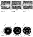
- the optimum conversion zone is generally very limited in temperature range as shown by the FIGS. 1A, 1B, and 1C respectively on three different catalysts: Cu-Zeo, Fe-Zeo, and Ti-Vanadium. It is noted that for the first two, the optimum window is considered to be between 300/350 ° C. For Ti-Vanadium, the window is wider between 280/420 ° C.
- the object of the present invention is to propose the use of a phase change material (PCM) whose phase change temperature is chosen so as to store the energy and restore it in the optimum temperature zone of the catalyst operation.
- PCM phase change material
- the present invention relates to a catalytic system with selective catalytic reduction (SCR) for treating combustion engine exhaust gas comprising a catalyzed medium traversed by the exhaust gas and thermally insulated by an outer layer of insulating material, characterized in that it comprises at least one cylindrical insert substantially in the center of said medium and consisting of phase-change material.
- SCR selective catalytic reduction
- the catalyzed medium may comprise on its outside a layer of phase-change material.
- the cylindrical insert may be tubular.
- the catalyzed medium may comprise a series of regularly distributed phase change material cylinder.
- the invention can find its use for hybrid vehicle catalytic devices.
- the invention can also find its use for rechargeable hybrid vehicle catalytic devices.
- FIGS. 1A, 1B, 1C have already been discussed above to demonstrate the advantage of the present invention.
- the present invention therefore aims to restrict the temperature window of the SCR system in order to optimize its operation by limiting the temperature differences with respect to the optimum catalytic conversion temperature so as to increase the duration of use of the catalyst in the system. zone of maximum efficiency of the catalyst and to increase its overall efficiency.
- the present system is based on the integration of a phase change material (PCM) within the selective catalytic reduction (SCR) system, or equivalent.
- PCM phase change material
- SCR selective catalytic reduction
- phase change material it may consist of a mixture of different materials.
- FIGS. 2A, 2B, 2C show in section a catalytic exhaust gas treatment system, the gas path being along the axis which passes through the center of the circular section.
- the Figure 2A shows the catalyzed bread 1 surrounded by a first layer of phase-change material 2, the assembly being thermally insulated by a thickness of thermal insulation 3.
- the catalyst cake contains at its center an insert 4 of MCP .
- the temperature of the catalyzed bread 2 is thus controlled by its center and its outer skin by means of the phase change material which has the capacity to absorb and restore local thermal energy provided by the gases and the catalytic conversion.
- the variant according to Figure 2C shows the MCP material distributed in the catalytic bread, in a section orthogonal to the longitudinal direction of the catalytic bread, in two orthogonal directions in this section, in the form of a series of cylindrical solid bars 6.
- the distribution of the MCP material may for example in a radial direction and in a circumferential direction.
- the number and size of the bars are chosen according to the size of the catalytic system and the operating conditions.
- Their provision in the catalytic medium follows an optimal regular distribution rule to achieve the objective of controlling the temperature of said medium.
- phase change material may be distributed over all or part of the length of the bread, so as to optimize the duration of the activation phases.
- this type of system is also interesting for hybrid vehicle applications, especially rechargeable, because it avoids defusing the conversion after prolonged engine shutdown.
Landscapes
- Engineering & Computer Science (AREA)
- Chemical & Material Sciences (AREA)
- Chemical Kinetics & Catalysis (AREA)
- Combustion & Propulsion (AREA)
- General Engineering & Computer Science (AREA)
- Mechanical Engineering (AREA)
- Health & Medical Sciences (AREA)
- Biomedical Technology (AREA)
- Oil, Petroleum & Natural Gas (AREA)
- General Chemical & Material Sciences (AREA)
- Toxicology (AREA)
- Analytical Chemistry (AREA)
- Environmental & Geological Engineering (AREA)
- Physics & Mathematics (AREA)
- Thermal Sciences (AREA)
- Exhaust Gas After Treatment (AREA)
- Exhaust Gas Treatment By Means Of Catalyst (AREA)
Abstract
Description
- La présente invention se situe dans le domaine des systèmes de traitement des gaz d'échappement de moteur à combustion interne, notamment pour véhicule.
- Elle est proposée pour les dispositifs à catalyse à réduction catalytique sélective SCR (pour « Selective Catalytic Réduction») permettant une réduction des émissions de NOx en sortie du moteur thermique.
- Plus précisément, l'invention propose des solutions pour contrôler la température interne des dispositifs catalytiques SCR afin d'en améliorer leurs performances globales.
- Les normes antipollution (en véhicule léger et poids lourd) imposent des émissions de gaz en sortie des systèmes de post-traitement des gaz d'échappement très faibles (de l'ordre de 0,4 g/kW/h pour les émissions de NOx en poids-lourd pour la norme Euro 6).
- Pour cela, les solutions de catalyse à l'échappement proposées nécessitent des efficacités de conversion du système SCR très élevées (supérieures à 95%) qui est actuellement un challenge compte-tenu notamment de la gamme de température à laquelle est soumise le système catalytique.
- Ainsi, les températures des gaz d'échappement qui traversent le support catalytique pendant le cycle de normalisation sont parfois très défavorables, avec des valeurs de températures faibles ne permettant pas la conversion des NOx, ou très élevées, ce qui oxyde le réducteur (généralement du nitrate d'ammonium, NH3) et empêche le stockage de ce réducteur afin d'optimiser la conversion (phénomène dit de « relargage » ou « NH3 slip »).
- On sait que la zone de conversion optimale, notamment en système SCR, est généralement très limitée en plage de température comme le montrent les
figures 1A, 1B, et 1C respectivement sur de trois catalyseurs différents : Cu-Zeo, Fe-Zeo, et Ti-Vanadium. On constate que pour les deux premiers, la fenêtre optimale est considérée comme pouvant être comprise entre 300/350°C. Pour Ti-Vanadium, la fenêtre est plus large entre 280/420°C environ. - Pour atteindre les efficacités de conversion demandées par les futures normes, il est donc nécessaire d'essayer de maintenir la température du système catalytique dans une plage restreinte déterminée.
- Aucun dispositif à base de matériaux à changement de phase n'a été proposé pour résoudre le problème pour une application « SCR » visant à contrôler la plage de température de fonctionnement afin d'optimiser la conversion et mieux gérer le stockage du NH3 au sein du catalyseur.
- L'objet de la présente invention est de proposer l'utilisation d'un matériau à changement de phase (MCP) dont la température de changement de phase est choisie de manière à stocker l'énergie et la restituer dans la zone de température optimale de fonctionnement du catalyseur.
- Ainsi, la présente invention concerne un système catalytique à réduction catalytique sélective (SCR) de traitement de gaz d'échappement de moteur à combustion comportant un milieu catalysé traversé par les gaz d'échappement et isolé thermiquement par une couche extérieure de matériau isolant, caractérisé en ce qu'il comporte au moins un insert cylindrique sensiblement au centre dudit milieu et constitué de matériau à changement de phase.
- Le milieu catalysé peut comporter sur son extérieur une couche de matériau à changement de phase.
- L'insert cylindrique peut être tubulaire.
- Le milieu catalysé peut comporter une série de cylindre de matériau à changement de phase répartie régulièrement.
- L'invention peut trouver son utilisation pour des dispositifs à catalyse de véhicule hybride.
- L'invention peut également trouver son utilisation pour des dispositifs à catalyse de véhicule hybride rechargeable.
- La présente invention sera mieux comprise et ses avantages apparaîtront plus clairement à la lecture des mises en oeuvre, nullement limitatives, illustrées par les figures ci-après annexées parmi lesquelles :
- les
figures 1A, 1B, 1C illustrent les plages de fonctionnement pour trois catalyseurs, - les
figures 2A, 2B, 2C illustrent des modes de réalisation selon l'invention. - Les
figures 1A, 1B, 1C ont déjà été commentées ci-dessus pour démontrer l'avantage de la présente invention. - La présente invention a donc pour objectif de restreindre la fenêtre de température du système SCR afin d'optimiser son fonctionnement en limitant les écarts de température par rapport à la température optimale de conversion catalytique de façon à augmenter la durée d'utilisation du catalyseur dans la zone d'efficacité maximale du catalyseur et d'augmenter globalement son efficacité.
- Ainsi, le système permet :
- de rapprocher les efficacités moyennes de fonctionnement au plus proche de l'efficacité maximale du support catalytique,
- de limiter les excursions dans les zones de faibles températures et donc de faibles efficacités,
- de limiter l'oxydation du réducteur (NH3) lors des excursions dans les fortes températures,
- de faciliter la gestion du stockage du réducteur (NH3) au sein du catalyseur, car les augmentations brutales de température ont des effets négatifs sur le relargage du NH3 stocké (« NH3 slip »),
- d'optimiser la durée de vie du catalyseur en écrêtant les pics de température extrêmes, provenant d'une utilisation soutenue du moteur thermique, ou d'une régénération de filtre à particules placé en amont du système SCR.
- Le présent système est basé sur l'intégration d'un matériau à changement de phase (MCP) au sein du système à réduction catalytique sélective (SCR), ou équivalent. Ce MCP est choisi pour avoir une température de changement d'état optimale par rapport à la plage de température d'efficacité maximale du système SCR.
- Il est recommandé de choisir un MCP dont la température de changement d'état est proche de la température de fonctionnement optimale du catalyseur, de façon à maximiser la durée d'utilisation autour de cette température.
- Pour régler le fonctionnement du matériau à changement de phase, il peut être constitué de mélange de matériaux différents.
- Diverses implantations peuvent être envisagées selon les
figures 2A, 2B, 2C qui montrent en coupe d'un système de traitement des gaz d'échappement par catalyse, le trajet des gaz étant selon l'axe qui passe par le centre de la coupe circulaire. - La
figure 2A montre le pain catalysé 1 entouré par une première couche de matériau à changement de phase 2, l'ensemble étant isolé thermiquement par une épaisseur d'isolant thermique 3. Dans cette variante, le pain de catalyse contient en son centre un insert 4 de MCP. La température du pain catalysé 2 est ainsi contrôlée par son centre et sa peau extérieure par le moyen du matériau à changement de phase qui a la capacité d'absorber et de restituer de l'énergie thermique locale fournie par les gaz et la conversion catalytique. - La variante selon la
figure 2B montre que l'on dispose uniquement un insert cylindrique creux 5 de MCP au sein du pain catalysé. - La variante selon la
figure 2C montre le matériau MCP réparti dans le pain catalytique, dans une section orthogonale à la direction longitudinale du pain catalytique, selon deux directions orthogonales dans cette section, sous forme d'une série de barreaux pleins cylindriques 6. La répartition du matériau MCP peut par exemple se faire selon une direction radiale et selon une direction circonférentielle. Le nombre et la dimension des barreaux sont choisis en fonction de la taille du système catalytique et les conditions de fonctionnement. Leur disposition dans le milieu catalytique suit une règle de répartition régulière optimale pour atteindre l'objectif de contrôle de la température dudit milieu. - Pour chaque variante, le matériau à changement de phase peut être réparti sur tout ou partie de la longueur du pain, de façon à pouvoir notamment optimiser la durée des phases d'activation.
- Les différentes variantes proposées présentent des avantages différents suivant leur utilisation lors d'un démarrage à froid ou en fonctionnement à chaud.
- Avantageusement, ce type de système est également intéressant pour les applications de véhicules hybrides, notamment rechargeables, car il permet d'éviter le désamorçage de la conversion après l'arrêt prolongé du moteur.
Claims (6)
- Système catalytique à réduction catalytique sélective (SCR) de traitement de gaz d'échappement de moteur à combustion interne comportant un milieu catalysé (1) traversé par les gaz d'échappement et isolé thermiquement par une couche extérieure de matériau isolant (3), caractérisé en ce qu'il comporte au moins un insert cylindrique (4 ; 5 ; 6) sensiblement au centre dudit milieu et constitué de matériau à changement de phase (MCP).
- Système catalytique à réduction catalytique sélective selon la revendication 1, dans lequel le milieu catalysé comporte sur son extérieur une couche (2) de matériau à changement de phase (MCP).
- Système catalytique à réduction catalytique sélective selon l'une des revendications 1 ou 2, dans lequel ledit insert cylindrique est tubulaire (5).
- Système catalytique à réduction catalytique sélective selon l'une des revendications précédentes, dans lequel le milieu catalysé comporte une série de cylindre de matériau à changement de phase (MCP) répartie régulièrement, dans une section orthogonale à la direction longitudinale du milieu catalysé.
- Utilisation du système catalytique à réduction catalytique sélective selon l'une des revendications 1 à 5, pour des dispositifs à catalyse de véhicule hybride.
- Utilisation du système catalytique à réduction catalytique sélective selon la revendication 5, pour des dispositifs à catalyse de véhicule hybride rechargeable.
Applications Claiming Priority (1)
| Application Number | Priority Date | Filing Date | Title |
|---|---|---|---|
| FR1755488A FR3067755B1 (fr) | 2017-06-16 | 2017-06-16 | Systeme d'optimisation de la temperature de catalyseurs a reduction catalytique selective scr |
Publications (1)
| Publication Number | Publication Date |
|---|---|
| EP3418519A1 true EP3418519A1 (fr) | 2018-12-26 |
Family
ID=60080928
Family Applications (1)
| Application Number | Title | Priority Date | Filing Date |
|---|---|---|---|
| EP18305595.3A Withdrawn EP3418519A1 (fr) | 2017-06-16 | 2018-05-15 | Systeme d'optimisation de la temperature de catalyseurs a reduction catalytique selective scr |
Country Status (2)
| Country | Link |
|---|---|
| EP (1) | EP3418519A1 (fr) |
| FR (1) | FR3067755B1 (fr) |
Cited By (1)
| Publication number | Priority date | Publication date | Assignee | Title |
|---|---|---|---|---|
| CN112403459A (zh) * | 2020-12-12 | 2021-02-26 | 宁波大学 | 一种基于金属相变微胶囊的低温scr催化剂及其制备方法 |
Citations (4)
| Publication number | Priority date | Publication date | Assignee | Title |
|---|---|---|---|---|
| US20030017086A1 (en) * | 2000-02-02 | 2003-01-23 | Brueck Rolf | Combination of honeycomb body and heat accumulator and method for the operation thereof |
| US20110048388A1 (en) * | 2009-09-03 | 2011-03-03 | Ngk Insulators, Ltd. | Heat accumulation element |
| US20150283504A1 (en) * | 2014-04-07 | 2015-10-08 | Ford Global Technologies, Llc | Temperature maintenance and regulation of vehicle exhaust catalyst systems with phase change materials |
| US20150285121A1 (en) * | 2014-04-07 | 2015-10-08 | Ford Global Technologies, Llc | Temperature maintenance and regulation of vehicle exhaust catalyst systems with phase change materials |
-
2017
- 2017-06-16 FR FR1755488A patent/FR3067755B1/fr not_active Expired - Fee Related
-
2018
- 2018-05-15 EP EP18305595.3A patent/EP3418519A1/fr not_active Withdrawn
Patent Citations (4)
| Publication number | Priority date | Publication date | Assignee | Title |
|---|---|---|---|---|
| US20030017086A1 (en) * | 2000-02-02 | 2003-01-23 | Brueck Rolf | Combination of honeycomb body and heat accumulator and method for the operation thereof |
| US20110048388A1 (en) * | 2009-09-03 | 2011-03-03 | Ngk Insulators, Ltd. | Heat accumulation element |
| US20150283504A1 (en) * | 2014-04-07 | 2015-10-08 | Ford Global Technologies, Llc | Temperature maintenance and regulation of vehicle exhaust catalyst systems with phase change materials |
| US20150285121A1 (en) * | 2014-04-07 | 2015-10-08 | Ford Global Technologies, Llc | Temperature maintenance and regulation of vehicle exhaust catalyst systems with phase change materials |
Cited By (2)
| Publication number | Priority date | Publication date | Assignee | Title |
|---|---|---|---|---|
| CN112403459A (zh) * | 2020-12-12 | 2021-02-26 | 宁波大学 | 一种基于金属相变微胶囊的低温scr催化剂及其制备方法 |
| CN112403459B (zh) * | 2020-12-12 | 2022-05-24 | 宁波大学 | 一种基于金属相变微胶囊的低温scr催化剂及其制备方法 |
Also Published As
| Publication number | Publication date |
|---|---|
| FR3067755B1 (fr) | 2019-06-21 |
| FR3067755A1 (fr) | 2018-12-21 |
Similar Documents
| Publication | Publication Date | Title |
|---|---|---|
| EP4069564B1 (fr) | Procede et calculateur de gestion d'une mise en fonctionnement d'un vehicule automobile de type hybride | |
| US9181838B2 (en) | Temperature maintenance and regulation of vehicle exhaust catalyst systems with phase change materials | |
| JP2012512359A (ja) | 排気ガスから電気エネルギーを生成する装置 | |
| US10265657B2 (en) | Temperature maintenance and regulation of vehicle exhaust catalyst systems with phase change materials | |
| FR2778815A1 (fr) | Dispositif de chauffage magnetique | |
| FR2965855A1 (fr) | Procede et dispositif de gestion de la temperature d'une installation de nettoyage de gaz d'echappement | |
| FR3067755B1 (fr) | Systeme d'optimisation de la temperature de catalyseurs a reduction catalytique selective scr | |
| WO2016193598A1 (fr) | Ensemble moteur turbocompressé a deux conduits d'échappement et vanne de régulation | |
| FR3007068A3 (fr) | Cone plat d'entree de pot catalytique | |
| JP2004138013A (ja) | 排ガス浄化構造 | |
| FR3053288A1 (fr) | Circuit de climatisation reversible de vehicule automobile et procedes de fonctionnement | |
| EP2084025B1 (fr) | Systeme de chauffage pour vehicule couple a un systeme egr | |
| FR2835565A1 (fr) | Procede de gestion de moyens de decolmatage d'un filtre a particules | |
| FR2910533A1 (fr) | Dispositif pour la regeneration d'un systeme de depollution des gaz d'echappement d'un moteur thermique | |
| WO2021254780A1 (fr) | Dispositif de chauffage électrique de catalyseur de gaz d'échappement | |
| CN110094250B (zh) | 内燃机的排气净化装置 | |
| FR3066408B1 (fr) | Dispositif de post-traitement des gaz d’echappement d’un moteur thermique | |
| EP3415732B1 (fr) | Système catalytique de traitement de gaz d'échappement de véhicule hybride comportant des moyens de stockage de la chaleur | |
| FR3002000A1 (fr) | Ensemble comportant un ecran thermique permettant le chauffage d'un reservoir de reducteur | |
| FR2779177A1 (fr) | Dispositif d'echappement a filtre a particules | |
| FR2995908A1 (fr) | Composition de fluide caloporteur. | |
| EP1589199A1 (fr) | Dispositif de purification de gaz d'échappement | |
| FR2904656A1 (fr) | Dispositif de traitement de polluants contenus dans des effluents gazeux d'un vehicule automobile et procede associe. | |
| FR3065921A1 (fr) | Vehicule equipe d’un systeme de depollution des gaz d’echappement | |
| FR3120095A1 (fr) | Organe de chauffage, procédé de fabrication, système de purification de gaz d’échappement, ligne d’échappement et véhicule |
Legal Events
| Date | Code | Title | Description |
|---|---|---|---|
| PUAI | Public reference made under article 153(3) epc to a published international application that has entered the european phase |
Free format text: ORIGINAL CODE: 0009012 |
|
| STAA | Information on the status of an ep patent application or granted ep patent |
Free format text: STATUS: THE APPLICATION HAS BEEN PUBLISHED |
|
| AK | Designated contracting states |
Kind code of ref document: A1 Designated state(s): AL AT BE BG CH CY CZ DE DK EE ES FI FR GB GR HR HU IE IS IT LI LT LU LV MC MK MT NL NO PL PT RO RS SE SI SK SM TR |
|
| AX | Request for extension of the european patent |
Extension state: BA ME |
|
| STAA | Information on the status of an ep patent application or granted ep patent |
Free format text: STATUS: REQUEST FOR EXAMINATION WAS MADE |
|
| 17P | Request for examination filed |
Effective date: 20190626 |
|
| RBV | Designated contracting states (corrected) |
Designated state(s): AL AT BE BG CH CY CZ DE DK EE ES FI FR GB GR HR HU IE IS IT LI LT LU LV MC MK MT NL NO PL PT RO RS SE SI SK SM TR |
|
| STAA | Information on the status of an ep patent application or granted ep patent |
Free format text: STATUS: EXAMINATION IS IN PROGRESS |
|
| 17Q | First examination report despatched |
Effective date: 20211022 |
|
| GRAP | Despatch of communication of intention to grant a patent |
Free format text: ORIGINAL CODE: EPIDOSNIGR1 |
|
| STAA | Information on the status of an ep patent application or granted ep patent |
Free format text: STATUS: GRANT OF PATENT IS INTENDED |
|
| INTG | Intention to grant announced |
Effective date: 20230524 |
|
| STAA | Information on the status of an ep patent application or granted ep patent |
Free format text: STATUS: THE APPLICATION IS DEEMED TO BE WITHDRAWN |
|
| 18D | Application deemed to be withdrawn |
Effective date: 20231005 |