EP3418481A1 - A motor vehicle having a manual rear closure member - Google Patents
A motor vehicle having a manual rear closure member Download PDFInfo
- Publication number
- EP3418481A1 EP3418481A1 EP18156063.2A EP18156063A EP3418481A1 EP 3418481 A1 EP3418481 A1 EP 3418481A1 EP 18156063 A EP18156063 A EP 18156063A EP 3418481 A1 EP3418481 A1 EP 3418481A1
- Authority
- EP
- European Patent Office
- Prior art keywords
- closure member
- rear closure
- motor vehicle
- hinge
- closing direction
- Prior art date
- Legal status (The legal status is an assumption and is not a legal conclusion. Google has not performed a legal analysis and makes no representation as to the accuracy of the status listed.)
- Granted
Links
Images



Classifications
-
- E—FIXED CONSTRUCTIONS
- E05—LOCKS; KEYS; WINDOW OR DOOR FITTINGS; SAFES
- E05B—LOCKS; ACCESSORIES THEREFOR; HANDCUFFS
- E05B83/00—Vehicle locks specially adapted for particular types of wing or vehicle
- E05B83/16—Locks for luggage compartments, car boot lids or car bonnets
- E05B83/18—Locks for luggage compartments, car boot lids or car bonnets for car boot lids or rear luggage compartments
-
- E—FIXED CONSTRUCTIONS
- E05—LOCKS; KEYS; WINDOW OR DOOR FITTINGS; SAFES
- E05C—BOLTS OR FASTENING DEVICES FOR WINGS, SPECIALLY FOR DOORS OR WINDOWS
- E05C17/00—Devices for holding wings open; Devices for limiting opening of wings or for holding wings open by a movable member extending between frame and wing; Braking devices, stops or buffers, combined therewith
- E05C17/02—Devices for holding wings open; Devices for limiting opening of wings or for holding wings open by a movable member extending between frame and wing; Braking devices, stops or buffers, combined therewith by mechanical means
-
- E—FIXED CONSTRUCTIONS
- E05—LOCKS; KEYS; WINDOW OR DOOR FITTINGS; SAFES
- E05D—HINGES OR SUSPENSION DEVICES FOR DOORS, WINDOWS OR WINGS
- E05D11/00—Additional features or accessories of hinges
- E05D11/10—Devices for preventing movement between relatively-movable hinge parts
- E05D11/1007—Devices for preventing movement between relatively-movable hinge parts with positive locking
-
- B—PERFORMING OPERATIONS; TRANSPORTING
- B60—VEHICLES IN GENERAL
- B60J—WINDOWS, WINDSCREENS, NON-FIXED ROOFS, DOORS, OR SIMILAR DEVICES FOR VEHICLES; REMOVABLE EXTERNAL PROTECTIVE COVERINGS SPECIALLY ADAPTED FOR VEHICLES
- B60J5/00—Doors
- B60J5/10—Doors arranged at the vehicle rear
- B60J5/101—Doors arranged at the vehicle rear for non-load transporting vehicles, i.e. family cars including vans
-
- E—FIXED CONSTRUCTIONS
- E05—LOCKS; KEYS; WINDOW OR DOOR FITTINGS; SAFES
- E05B—LOCKS; ACCESSORIES THEREFOR; HANDCUFFS
- E05B81/00—Power-actuated vehicle locks
- E05B81/02—Power-actuated vehicle locks characterised by the type of actuators used
- E05B81/04—Electrical
- E05B81/08—Electrical using electromagnets or solenoids
-
- E—FIXED CONSTRUCTIONS
- E05—LOCKS; KEYS; WINDOW OR DOOR FITTINGS; SAFES
- E05B—LOCKS; ACCESSORIES THEREFOR; HANDCUFFS
- E05B81/00—Power-actuated vehicle locks
- E05B81/02—Power-actuated vehicle locks characterised by the type of actuators used
- E05B81/10—Hydraulic or pneumatic
-
- E—FIXED CONSTRUCTIONS
- E05—LOCKS; KEYS; WINDOW OR DOOR FITTINGS; SAFES
- E05B—LOCKS; ACCESSORIES THEREFOR; HANDCUFFS
- E05B81/00—Power-actuated vehicle locks
- E05B81/12—Power-actuated vehicle locks characterised by the function or purpose of the powered actuators
- E05B81/18—Power-actuated vehicle locks characterised by the function or purpose of the powered actuators to effect movement of a bolt or bolts
-
- E—FIXED CONSTRUCTIONS
- E05—LOCKS; KEYS; WINDOW OR DOOR FITTINGS; SAFES
- E05B—LOCKS; ACCESSORIES THEREFOR; HANDCUFFS
- E05B81/00—Power-actuated vehicle locks
- E05B81/54—Electrical circuits
- E05B81/64—Monitoring or sensing, e.g. by using switches or sensors
-
- E—FIXED CONSTRUCTIONS
- E05—LOCKS; KEYS; WINDOW OR DOOR FITTINGS; SAFES
- E05D—HINGES OR SUSPENSION DEVICES FOR DOORS, WINDOWS OR WINGS
- E05D11/00—Additional features or accessories of hinges
- E05D11/10—Devices for preventing movement between relatively-movable hinge parts
-
- E—FIXED CONSTRUCTIONS
- E05—LOCKS; KEYS; WINDOW OR DOOR FITTINGS; SAFES
- E05D—HINGES OR SUSPENSION DEVICES FOR DOORS, WINDOWS OR WINGS
- E05D11/00—Additional features or accessories of hinges
- E05D11/10—Devices for preventing movement between relatively-movable hinge parts
- E05D11/1014—Devices for preventing movement between relatively-movable hinge parts for maintaining the hinge in only one position, e.g. closed
-
- E—FIXED CONSTRUCTIONS
- E05—LOCKS; KEYS; WINDOW OR DOOR FITTINGS; SAFES
- E05D—HINGES OR SUSPENSION DEVICES FOR DOORS, WINDOWS OR WINGS
- E05D11/00—Additional features or accessories of hinges
- E05D11/10—Devices for preventing movement between relatively-movable hinge parts
- E05D11/1028—Devices for preventing movement between relatively-movable hinge parts for maintaining the hinge in two or more positions, e.g. intermediate or fully open
-
- E—FIXED CONSTRUCTIONS
- E05—LOCKS; KEYS; WINDOW OR DOOR FITTINGS; SAFES
- E05F—DEVICES FOR MOVING WINGS INTO OPEN OR CLOSED POSITION; CHECKS FOR WINGS; WING FITTINGS NOT OTHERWISE PROVIDED FOR, CONCERNED WITH THE FUNCTIONING OF THE WING
- E05F15/00—Power-operated mechanisms for wings
- E05F15/40—Safety devices, e.g. detection of obstructions or end positions
-
- E—FIXED CONSTRUCTIONS
- E05—LOCKS; KEYS; WINDOW OR DOOR FITTINGS; SAFES
- E05F—DEVICES FOR MOVING WINGS INTO OPEN OR CLOSED POSITION; CHECKS FOR WINGS; WING FITTINGS NOT OTHERWISE PROVIDED FOR, CONCERNED WITH THE FUNCTIONING OF THE WING
- E05F15/00—Power-operated mechanisms for wings
- E05F15/40—Safety devices, e.g. detection of obstructions or end positions
- E05F15/42—Detection using safety edges
- E05F15/43—Detection using safety edges responsive to disruption of energy beams, e.g. light or sound
-
- E—FIXED CONSTRUCTIONS
- E05—LOCKS; KEYS; WINDOW OR DOOR FITTINGS; SAFES
- E05F—DEVICES FOR MOVING WINGS INTO OPEN OR CLOSED POSITION; CHECKS FOR WINGS; WING FITTINGS NOT OTHERWISE PROVIDED FOR, CONCERNED WITH THE FUNCTIONING OF THE WING
- E05F5/00—Braking devices, e.g. checks; Stops; Buffers
-
- E—FIXED CONSTRUCTIONS
- E05—LOCKS; KEYS; WINDOW OR DOOR FITTINGS; SAFES
- E05D—HINGES OR SUSPENSION DEVICES FOR DOORS, WINDOWS OR WINGS
- E05D3/00—Hinges with pins
- E05D3/02—Hinges with pins with one pin
-
- E—FIXED CONSTRUCTIONS
- E05—LOCKS; KEYS; WINDOW OR DOOR FITTINGS; SAFES
- E05F—DEVICES FOR MOVING WINGS INTO OPEN OR CLOSED POSITION; CHECKS FOR WINGS; WING FITTINGS NOT OTHERWISE PROVIDED FOR, CONCERNED WITH THE FUNCTIONING OF THE WING
- E05F15/00—Power-operated mechanisms for wings
- E05F15/40—Safety devices, e.g. detection of obstructions or end positions
- E05F15/42—Detection using safety edges
- E05F15/43—Detection using safety edges responsive to disruption of energy beams, e.g. light or sound
- E05F2015/432—Detection using safety edges responsive to disruption of energy beams, e.g. light or sound with acoustical sensors
-
- E—FIXED CONSTRUCTIONS
- E05—LOCKS; KEYS; WINDOW OR DOOR FITTINGS; SAFES
- E05Y—INDEXING SCHEME ASSOCIATED WITH SUBCLASSES E05D AND E05F, RELATING TO CONSTRUCTION ELEMENTS, ELECTRIC CONTROL, POWER SUPPLY, POWER SIGNAL OR TRANSMISSION, USER INTERFACES, MOUNTING OR COUPLING, DETAILS, ACCESSORIES, AUXILIARY OPERATIONS NOT OTHERWISE PROVIDED FOR, APPLICATION THEREOF
- E05Y2201/00—Constructional elements; Accessories therefor
- E05Y2201/20—Brakes; Disengaging means; Holders; Stops; Valves; Accessories therefor
- E05Y2201/21—Brakes
-
- E—FIXED CONSTRUCTIONS
- E05—LOCKS; KEYS; WINDOW OR DOOR FITTINGS; SAFES
- E05Y—INDEXING SCHEME ASSOCIATED WITH SUBCLASSES E05D AND E05F, RELATING TO CONSTRUCTION ELEMENTS, ELECTRIC CONTROL, POWER SUPPLY, POWER SIGNAL OR TRANSMISSION, USER INTERFACES, MOUNTING OR COUPLING, DETAILS, ACCESSORIES, AUXILIARY OPERATIONS NOT OTHERWISE PROVIDED FOR, APPLICATION THEREOF
- E05Y2201/00—Constructional elements; Accessories therefor
- E05Y2201/20—Brakes; Disengaging means; Holders; Stops; Valves; Accessories therefor
- E05Y2201/218—Holders
-
- E—FIXED CONSTRUCTIONS
- E05—LOCKS; KEYS; WINDOW OR DOOR FITTINGS; SAFES
- E05Y—INDEXING SCHEME ASSOCIATED WITH SUBCLASSES E05D AND E05F, RELATING TO CONSTRUCTION ELEMENTS, ELECTRIC CONTROL, POWER SUPPLY, POWER SIGNAL OR TRANSMISSION, USER INTERFACES, MOUNTING OR COUPLING, DETAILS, ACCESSORIES, AUXILIARY OPERATIONS NOT OTHERWISE PROVIDED FOR, APPLICATION THEREOF
- E05Y2201/00—Constructional elements; Accessories therefor
- E05Y2201/20—Brakes; Disengaging means; Holders; Stops; Valves; Accessories therefor
- E05Y2201/218—Holders
- E05Y2201/22—Locks
-
- E—FIXED CONSTRUCTIONS
- E05—LOCKS; KEYS; WINDOW OR DOOR FITTINGS; SAFES
- E05Y—INDEXING SCHEME ASSOCIATED WITH SUBCLASSES E05D AND E05F, RELATING TO CONSTRUCTION ELEMENTS, ELECTRIC CONTROL, POWER SUPPLY, POWER SIGNAL OR TRANSMISSION, USER INTERFACES, MOUNTING OR COUPLING, DETAILS, ACCESSORIES, AUXILIARY OPERATIONS NOT OTHERWISE PROVIDED FOR, APPLICATION THEREOF
- E05Y2201/00—Constructional elements; Accessories therefor
- E05Y2201/20—Brakes; Disengaging means; Holders; Stops; Valves; Accessories therefor
- E05Y2201/23—Actuation thereof
- E05Y2201/232—Actuation thereof by automatically acting means
-
- E—FIXED CONSTRUCTIONS
- E05—LOCKS; KEYS; WINDOW OR DOOR FITTINGS; SAFES
- E05Y—INDEXING SCHEME ASSOCIATED WITH SUBCLASSES E05D AND E05F, RELATING TO CONSTRUCTION ELEMENTS, ELECTRIC CONTROL, POWER SUPPLY, POWER SIGNAL OR TRANSMISSION, USER INTERFACES, MOUNTING OR COUPLING, DETAILS, ACCESSORIES, AUXILIARY OPERATIONS NOT OTHERWISE PROVIDED FOR, APPLICATION THEREOF
- E05Y2201/00—Constructional elements; Accessories therefor
- E05Y2201/40—Motors; Magnets; Springs; Weights; Accessories therefor
- E05Y2201/404—Function thereof
- E05Y2201/408—Function thereof for braking
-
- E—FIXED CONSTRUCTIONS
- E05—LOCKS; KEYS; WINDOW OR DOOR FITTINGS; SAFES
- E05Y—INDEXING SCHEME ASSOCIATED WITH SUBCLASSES E05D AND E05F, RELATING TO CONSTRUCTION ELEMENTS, ELECTRIC CONTROL, POWER SUPPLY, POWER SIGNAL OR TRANSMISSION, USER INTERFACES, MOUNTING OR COUPLING, DETAILS, ACCESSORIES, AUXILIARY OPERATIONS NOT OTHERWISE PROVIDED FOR, APPLICATION THEREOF
- E05Y2201/00—Constructional elements; Accessories therefor
- E05Y2201/40—Motors; Magnets; Springs; Weights; Accessories therefor
- E05Y2201/43—Motors
- E05Y2201/448—Fluid motors; Details thereof
-
- E—FIXED CONSTRUCTIONS
- E05—LOCKS; KEYS; WINDOW OR DOOR FITTINGS; SAFES
- E05Y—INDEXING SCHEME ASSOCIATED WITH SUBCLASSES E05D AND E05F, RELATING TO CONSTRUCTION ELEMENTS, ELECTRIC CONTROL, POWER SUPPLY, POWER SIGNAL OR TRANSMISSION, USER INTERFACES, MOUNTING OR COUPLING, DETAILS, ACCESSORIES, AUXILIARY OPERATIONS NOT OTHERWISE PROVIDED FOR, APPLICATION THEREOF
- E05Y2201/00—Constructional elements; Accessories therefor
- E05Y2201/40—Motors; Magnets; Springs; Weights; Accessories therefor
- E05Y2201/43—Motors
- E05Y2201/448—Fluid motors; Details thereof
- E05Y2201/458—Valves
-
- E—FIXED CONSTRUCTIONS
- E05—LOCKS; KEYS; WINDOW OR DOOR FITTINGS; SAFES
- E05Y—INDEXING SCHEME ASSOCIATED WITH SUBCLASSES E05D AND E05F, RELATING TO CONSTRUCTION ELEMENTS, ELECTRIC CONTROL, POWER SUPPLY, POWER SIGNAL OR TRANSMISSION, USER INTERFACES, MOUNTING OR COUPLING, DETAILS, ACCESSORIES, AUXILIARY OPERATIONS NOT OTHERWISE PROVIDED FOR, APPLICATION THEREOF
- E05Y2201/00—Constructional elements; Accessories therefor
- E05Y2201/60—Suspension or transmission members; Accessories therefor
- E05Y2201/622—Suspension or transmission members elements
- E05Y2201/71—Toothed gearing
-
- E—FIXED CONSTRUCTIONS
- E05—LOCKS; KEYS; WINDOW OR DOOR FITTINGS; SAFES
- E05Y—INDEXING SCHEME ASSOCIATED WITH SUBCLASSES E05D AND E05F, RELATING TO CONSTRUCTION ELEMENTS, ELECTRIC CONTROL, POWER SUPPLY, POWER SIGNAL OR TRANSMISSION, USER INTERFACES, MOUNTING OR COUPLING, DETAILS, ACCESSORIES, AUXILIARY OPERATIONS NOT OTHERWISE PROVIDED FOR, APPLICATION THEREOF
- E05Y2201/00—Constructional elements; Accessories therefor
- E05Y2201/60—Suspension or transmission members; Accessories therefor
- E05Y2201/622—Suspension or transmission members elements
- E05Y2201/71—Toothed gearing
- E05Y2201/712—Toothed gearing with incomplete toothing
-
- E—FIXED CONSTRUCTIONS
- E05—LOCKS; KEYS; WINDOW OR DOOR FITTINGS; SAFES
- E05Y—INDEXING SCHEME ASSOCIATED WITH SUBCLASSES E05D AND E05F, RELATING TO CONSTRUCTION ELEMENTS, ELECTRIC CONTROL, POWER SUPPLY, POWER SIGNAL OR TRANSMISSION, USER INTERFACES, MOUNTING OR COUPLING, DETAILS, ACCESSORIES, AUXILIARY OPERATIONS NOT OTHERWISE PROVIDED FOR, APPLICATION THEREOF
- E05Y2400/00—Electronic control; Electrical power; Power supply; Power or signal transmission; User interfaces
- E05Y2400/10—Electronic control
- E05Y2400/20—Electronic control of brakes, disengaging means, holders or stops
-
- E—FIXED CONSTRUCTIONS
- E05—LOCKS; KEYS; WINDOW OR DOOR FITTINGS; SAFES
- E05Y—INDEXING SCHEME ASSOCIATED WITH SUBCLASSES E05D AND E05F, RELATING TO CONSTRUCTION ELEMENTS, ELECTRIC CONTROL, POWER SUPPLY, POWER SIGNAL OR TRANSMISSION, USER INTERFACES, MOUNTING OR COUPLING, DETAILS, ACCESSORIES, AUXILIARY OPERATIONS NOT OTHERWISE PROVIDED FOR, APPLICATION THEREOF
- E05Y2400/00—Electronic control; Electrical power; Power supply; Power or signal transmission; User interfaces
- E05Y2400/10—Electronic control
- E05Y2400/44—Sensors not directly associated with the wing movement
-
- E—FIXED CONSTRUCTIONS
- E05—LOCKS; KEYS; WINDOW OR DOOR FITTINGS; SAFES
- E05Y—INDEXING SCHEME ASSOCIATED WITH SUBCLASSES E05D AND E05F, RELATING TO CONSTRUCTION ELEMENTS, ELECTRIC CONTROL, POWER SUPPLY, POWER SIGNAL OR TRANSMISSION, USER INTERFACES, MOUNTING OR COUPLING, DETAILS, ACCESSORIES, AUXILIARY OPERATIONS NOT OTHERWISE PROVIDED FOR, APPLICATION THEREOF
- E05Y2400/00—Electronic control; Electrical power; Power supply; Power or signal transmission; User interfaces
- E05Y2400/10—Electronic control
- E05Y2400/44—Sensors not directly associated with the wing movement
- E05Y2400/446—Vehicle state sensors, e.g. parked or inclination
-
- E—FIXED CONSTRUCTIONS
- E05—LOCKS; KEYS; WINDOW OR DOOR FITTINGS; SAFES
- E05Y—INDEXING SCHEME ASSOCIATED WITH SUBCLASSES E05D AND E05F, RELATING TO CONSTRUCTION ELEMENTS, ELECTRIC CONTROL, POWER SUPPLY, POWER SIGNAL OR TRANSMISSION, USER INTERFACES, MOUNTING OR COUPLING, DETAILS, ACCESSORIES, AUXILIARY OPERATIONS NOT OTHERWISE PROVIDED FOR, APPLICATION THEREOF
- E05Y2400/00—Electronic control; Electrical power; Power supply; Power or signal transmission; User interfaces
- E05Y2400/10—Electronic control
- E05Y2400/52—Safety arrangements associated with the wing motor
- E05Y2400/53—Wing impact prevention or reduction
-
- E—FIXED CONSTRUCTIONS
- E05—LOCKS; KEYS; WINDOW OR DOOR FITTINGS; SAFES
- E05Y—INDEXING SCHEME ASSOCIATED WITH SUBCLASSES E05D AND E05F, RELATING TO CONSTRUCTION ELEMENTS, ELECTRIC CONTROL, POWER SUPPLY, POWER SIGNAL OR TRANSMISSION, USER INTERFACES, MOUNTING OR COUPLING, DETAILS, ACCESSORIES, AUXILIARY OPERATIONS NOT OTHERWISE PROVIDED FOR, APPLICATION THEREOF
- E05Y2900/00—Application of doors, windows, wings or fittings thereof
- E05Y2900/50—Application of doors, windows, wings or fittings thereof for vehicles
- E05Y2900/53—Type of wing
- E05Y2900/531—Doors
- E05Y2900/532—Back doors or end doors
-
- E—FIXED CONSTRUCTIONS
- E05—LOCKS; KEYS; WINDOW OR DOOR FITTINGS; SAFES
- E05Y—INDEXING SCHEME ASSOCIATED WITH SUBCLASSES E05D AND E05F, RELATING TO CONSTRUCTION ELEMENTS, ELECTRIC CONTROL, POWER SUPPLY, POWER SIGNAL OR TRANSMISSION, USER INTERFACES, MOUNTING OR COUPLING, DETAILS, ACCESSORIES, AUXILIARY OPERATIONS NOT OTHERWISE PROVIDED FOR, APPLICATION THEREOF
- E05Y2900/00—Application of doors, windows, wings or fittings thereof
- E05Y2900/50—Application of doors, windows, wings or fittings thereof for vehicles
- E05Y2900/53—Type of wing
- E05Y2900/546—Tailboards, tailgates or sideboards opening upwards
-
- E—FIXED CONSTRUCTIONS
- E05—LOCKS; KEYS; WINDOW OR DOOR FITTINGS; SAFES
- E05Y—INDEXING SCHEME ASSOCIATED WITH SUBCLASSES E05D AND E05F, RELATING TO CONSTRUCTION ELEMENTS, ELECTRIC CONTROL, POWER SUPPLY, POWER SIGNAL OR TRANSMISSION, USER INTERFACES, MOUNTING OR COUPLING, DETAILS, ACCESSORIES, AUXILIARY OPERATIONS NOT OTHERWISE PROVIDED FOR, APPLICATION THEREOF
- E05Y2900/00—Application of doors, windows, wings or fittings thereof
- E05Y2900/50—Application of doors, windows, wings or fittings thereof for vehicles
- E05Y2900/53—Type of wing
- E05Y2900/548—Trunk lids
-
- G—PHYSICS
- G01—MEASURING; TESTING
- G01S—RADIO DIRECTION-FINDING; RADIO NAVIGATION; DETERMINING DISTANCE OR VELOCITY BY USE OF RADIO WAVES; LOCATING OR PRESENCE-DETECTING BY USE OF THE REFLECTION OR RERADIATION OF RADIO WAVES; ANALOGOUS ARRANGEMENTS USING OTHER WAVES
- G01S15/00—Systems using the reflection or reradiation of acoustic waves, e.g. sonar systems
- G01S15/88—Sonar systems specially adapted for specific applications
- G01S15/93—Sonar systems specially adapted for specific applications for anti-collision purposes
- G01S15/931—Sonar systems specially adapted for specific applications for anti-collision purposes of land vehicles
- G01S2015/932—Sonar systems specially adapted for specific applications for anti-collision purposes of land vehicles for parking operations
Definitions
- This invention relates to motor vehicles and in particular to a motor vehicle having a manually operable rear closure member.
- a motor vehicle such as a hatchback motor vehicle, a multipurpose vehicle (MPV), a sports utility vehicle (SUV) or a van with a manually moveable rear closure member hingedly connected to the motor vehicle near an upper end to provide access to a rear compartment of the motor vehicle such as a trunk, boot, cargo area or luggage space.
- Such rear closure members are sometimes referred to as 'tailgates', 'trunk lids', 'rear hatches' or 'rear doors'.
- the final act is to close the rear closure member and this involves a user reaching up and pulling the rear closure member downwards.
- a typical rear closure member is heavy and requires considerable effort to close it in order to overcome pressure within gas struts normally used to hold the rear closure member in an open position. Once the closing process starts considerable momentum is generated and the process will normally not stop until the closure member reaches a closed position where it latches to part of a body structure of the motor vehicle.
- a motor vehicle having a top hinged rear closure member manually moveable between open and closed positions, an electronically controlled mechanism to prevent, at least when the rear closure member is in a fully open position, movement of the rear closure member in a closing direction, an electronic controller to control the operation of the electronically controlled mechanism and a number of rear parking sensors to provide an indication to the electronic controller of whether one or more objects lies within a rear protection zone wherein, if the parking sensors indicate that more than one object is located within the rear protection zone, the electronic controller is arranged to operate the electronically controlled mechanism to prevent movement of the rear closure member in a closing direction.
- the electronic controller may be arranged to operate the electronically controlled mechanism to prevent movement of the rear closure member in a closing direction only if the rear closure member is in a fully open position.
- the electronic controller may be arranged to operate the electronically controlled mechanism to prevent movement of the rear closure member in a closing direction when the rear closure member is in a partially closed position.
- the electronically controlled mechanism may be an electronically controlled latching mechanism comprising a solenoid actuator having a latching pin moveable into engagement with a hinge member forming one half of a hinge mechanism used to hingedly connect the rear closure member to a structural part of the motor vehicle so as to prevent movement of the hinge member and the solenoid actuator may be operable to move the latching pin into engagement with the hinge member when it is required to prevent movement of the rear closure member in a closing direction.
- the latching pin may be moved into engagement with an abutment surface on the hinge member when it is required to prevent movement of the rear closure member in a closing direction.
- the hinge member may be a first hinge member fastened to the rear closure member and the hinge mechanism may include a second hinge member pivotally connected to the first hinge member and fastened to part of a body structure of the motor vehicle and the solenoid actuator may be fastened to the second hinge member.
- the electronically controlled mechanism may comprise a pump drivingly connected between first and second hinge members forming a hinge mechanism used to hingedly connect the rear closure member to a body structure of the motor vehicle and an electronically controlled valve to prevent the flow of liquid from an outlet of the pump to an inlet of the pump through a recirculation circuit when it is required to prevent movement of the rear closure member in a closing direction.
- first hinge member may be a hinge member fastened to the rear closure member and the second hinge member may be a hinge member pivotally connected to the first hinge member and fastened to the body structure of the motor vehicle.
- the pump may be fastened to the second hinge member and may have a drive shaft drivingly connected by a gear wheel to a quadrant gear fastened to the first hinge member.
- a method of controlling the closing motion of a manually operated top hinged rear closure member of a motor vehicle comprising checking whether more than one object is located within a rear protection zone of the motor vehicle and, at least when the rear closure member is in a fully open position, preventing movement of the rear closure member in a closing direction if more than one object is located within the rear protection zone.
- the method may further comprise stopping motion of the rear closure member in a closing direction if the number of objects in the protection zone increases to more than one during closing of the rear closure member.
- Checking whether more than one object is located within a rear protection zone of the motor vehicle may comprise using rear parking sensors to check for the presence of objects in the rear protection zone.
- Preventing movement of the rear closure member in a closing direction may comprise using an electronically controlled mechanism to prevent movement in the closing direction.
- the method may further comprise using an electronic controller to operate the electronically controlled mechanism to prevent movement in the closing direction in response to a feedback from the rear parking sensors.
- a motor vehicle 1 having a body structure 2 to which is hingedly connected at a rear end thereof a rear closure member 5.
- the rear closure member 5 is a manually moveable closure member meaning that opening and closing of the rear closure member 5 is done manually.
- the rear closure member 5 is hingedly connected to the body structure 2 near a top end by means of a pair of spaced apart hinge mechanisms 7 which facilitate opening and closing of the rear closure member 5 about a substantially horizontal transverse pivot axis x-x.
- the motor vehicle 1 includes a safety system 10 the function of which is to reduce the risk of injury to persons not actively engaged in the closing of the rear closure member 5 when the rear closure member 5 is to be closed or, in some cases, is in the process of being closed.
- the safety system 10 comprises an electronic controller 15 arranged to receive inputs from a number of rear parking sensors 16, a rear closure member state input 17 and is arranged to control the operation of an electronically controlled mechanism 12 used to prevent the closing of the rear closure member 5 in certain circumstances.
- the rear parking sensors 16 provide an indication to the electronic controller of whether a person is within a predefined area to the rear of the motor vehicle 1 referred to herein as a protection zone PZ.
- the protection zone PZ is an area in which a person may accidentally be impacted against by the rear closure member 5 during the process of closing of the rear closure member 5 if a person closing the rear closure member 5 is not aware of their presence. This can include a person close enough to the motor vehicle to lean in to a rear luggage compartment during the rear closure closing process to retrieve an item or a person who is so close to the rear of the motor vehicle 1 that closing of the rear closure member will likely produce contact between the rear closure member 5 and that person.
- the electronic controller 15 is arranged to operate the electronically controlled mechanism 12 to prevent movement of the rear closure member 5 in the closing direction in response to a feedback from the rear parking sensors 16 when more than one object is located within the rear protection zone PZ of the motor vehicle 1 and the rear closure member 5 is in the fully open position. That is to say, the safety system 10 maintains the rear closure member 5 in a fully open position if more than one object is sensed to be in the protection zone PZ.
- the rear closure member state input 17 is in the case of this example used to indicate to the electronic controller 15 when the rear closure member 5 is in the fully open and closed states.
- the safety system 10 is arranged to not only maintain the rear closure member 5 in a fully open position if more than one object is sensed to be in the protection zone PZ when the rear closure is fully open but also to stop motion of the rear closure member 5 in a closing direction if the number of objects in the protection zone increases to more than one during closing of the rear closure member 5.
- FIG.3 to 6 there is shown a first embodiment of an electronically controlled mechanism 12 to prevent movement of the rear closure member 5 in the closing direction.
- the electronically controlled mechanism 12 is in the form of an electronically controlled latching mechanism comprising a solenoid actuator 18 having a latching pin 19 moveable into engagement with a hinge member 4 forming one half of one of the hinge mechanisms 7 used to hingedly connect the rear closure member 5 to the structural part 2 of the motor vehicle 1.
- the solenoid actuator 18 is operable in response to a control signal from the electronic controller 15 to move the latching pin 19 into engagement with the hinge member 4 when it is required to prevent movement of the rear closure member 5 in a closing direction and the rear closure member 5 is in a fully open position.
- the hinge member is a first hinge member 4 fastened to the rear closure member 5 and the hinge mechanism also includes a second hinge member 3 pivotally connected to the first hinge member 4 by a hinge pin 6.
- the second hinge member 3 is fastened to part of the body structure 2 of the motor vehicle 1.
- the hinge pin 6 is coaxially aligned with the pivot axis x-x about which the rear closure member 5 rotates during opening and closing.
- the solenoid actuator 18 is, in the case of this example, fastened to the second hinge member 3 but it will be appreciated that it could alternatively be fastened directly the body structure 2 of the motor vehicle 1.
- the latching pin 19 is biased by a spring (not shown) into an unlatched position as shown in Fig.6 and moved by the solenoid actuator 18 into engagement with the first hinge member 4 when it is required to prevent movement of the rear closure member 5 in a closing direction which is when more than one object is sensed to be within the protection zone PZ and the rear closure member 5 is in a fully open position as indicated by the rear closure state input 17.
- the latching pin 19 is moved into engagement with an abutment surface 4a on the first hinge member 4 when it is required to prevent movement of the rear closure member 5 in the closing direction but it will be appreciated that the latching pin 19 could alternatively be engageable with an abutment member secured to the first hinge member 4 or be engageable with an aperture formed in the first hinge member 4.
- solenoid actuator 18 could be mounted on the first hinge member 4 and the latching pin 19 would then engage in some manner with the second hinge member 3 to prevent movement of the rear closure member 5 from the fully open position when required.
- both of the hinge mechanisms 7 used to hingedly connect the rear closure member 5 to the body structure 2 could be provided with such electronically controlled latching mechanisms to prevent movement of the rear closure member 5 away from the fully open position when required.
- the solenoid actuator 18 is only switched on to displace the latching pin 19 into a latching position when there is more than one object (person) in the rear protection zone PZ and the rear closure member 5 is in a fully open position.
- the latching pin 19 can engage with the abutment surface 4a on the first hinge member 4. That is to say, the arrangement of this example can only hold the rear closure member 5 in the fully open position it cannot stop closing once it has started.
- FIG.7 and 8 there is shown a second embodiment of an electronically controlled mechanism 12 to prevent movement of the rear closure member 5 in the closing direction.
- the electronically controlled mechanism 12 is in this case in the form of an electronically controlled braking mechanism comprising a pump 50 drivingly connected between first and second hinge members 44, 43 forming one of the hinge mechanisms 7 used to hingedly connect the rear closure member 5 to the body structure 2 of the motor vehicle 1 and an electronically controlled valve 48 to selectively prevent the flow of fluid such as oil from an outlet 61 of the pump 60 to an inlet 62 of the pump 50 through a recirculation circuit 60 when it is required to prevent movement of the rear closure member 5 in a closing direction which is when more than one object is sensed to be within the protection zone PZ.
- an electronically controlled braking mechanism comprising a pump 50 drivingly connected between first and second hinge members 44, 43 forming one of the hinge mechanisms 7 used to hingedly connect the rear closure member 5 to the body structure 2 of the motor vehicle 1 and an electronically controlled valve 48 to selectively prevent the flow of fluid such as oil from an outlet 61 of the pump 60 to an inlet 62 of the pump 50 through a recirculation circuit 60 when it is required to prevent
- the first hinge member 44 is pivotally connected to the second hinge member 43 by a pivot pin 49 arranged coaxially with respect to the transverse pivot axis x-x about which the rear closure member 5 rotates between open and closed positions.
- the second hinge member 3 is fastened to the body structure 2 of the motor vehicle 1.
- the pump 50 has a rotor (not shown) connected to an input shaft 53 that has a gear wheel 52 fastened thereto that is drivingly connected to quadrant gear 51 fastened to the first hinge member 44.
- the pump 50 is therefore connected to the first hinge member 44 by the input shaft 53 and so, if the input shaft 53 is prevented from rotation, the rear closure member 5 that is fastened to the first hinge member 44 is also prevented from rotation thereby preventing movement of the rear closure member 5.
- the electronically controlled valve is in the form of a solenoid valve 48 operatively controlled by the electronic controller 15 that when closed prevents the flow of oil through the recirculation circuit 60 in the direction of the arrows "C" from the outlet 61 to the inlet 62 when it is required to prevent movement of the rear closure member 5 in the closing direction.
- a non-return valve “NRV” is arranged to bypass the solenoid valve 48 to permit flow in a direction opposite to that shown by the arrows "C" through the recirculation circuit 60 even if the solenoid valve 48 is closed. This allows the rear closure member 5 to be moved from closed to open even if there is more than one object in the rear protection zone PZ.
- the electronic controller 15 could be arranged to only close the solenoid valve 48 when there is more than one object in the rear protection zone PZ and the rear closure member 5 is sensed to be moving in a closing direction.
- the electronically controlled braking mechanism of this second embodiment can be used to prevent movement in the closing direction not only when the rear closure member 5 is in the fully open position but also during closing of the rear closure member 5. That is to say, if during the process of closing of the rear closure member 5, more than one object is sensed to be within the protection zone PZ because, for example, a person has entered the protection zone PZ during the closing process, then the electronic controller 15 can immediately close the solenoid valve 48 thereby preventing further motion of the rear closure member 5 in the closing direction.
- the predefined amount corresponds to a rear closure position where the risk of accidental injury to a third party is considered to be minimal.
- both of the hinge mechanisms 7 used to hingedly connect the rear closure member 5 to the body structure 2 could be provided with such electronically controlled braking mechanisms to prevent movement of the rear closure member 5 in the closing direction when required.
- braking mechanisms could be used in a similar manner to the braking mechanism shown in Figs. 7 and 8 .
- an electronically engageable clutch could be drivingly connected between the first and second hinge members and the electronic controller could be arranged to engage the clutch when it is required to prevent closing movement of the rear closure member.
- a double acting ram could be interposed between the body structure and the rear closure member and the flow of liquid from one end of the ram to an opposite end of the ram can be controlled by a solenoid valve that can be closed by an electronic controller when it is required to prevent closing movement of the rear closure member.
- FIG.9 there is shown a first embodiment of a method of controlling closing of a rear closure member of a motor vehicle such as the rear closure member 5 of the motor vehicle 1.
- the method 100 starts in box 110 by checking whether the motor vehicle is stationary and if it is not no action is taken. That is to say, the method 100 is only used when the motor vehicle is not moving.
- the method advances to box 120 to check whether the rear closure member is fully open. If the rear closure member is not fully open then the method returns to box 110 and will cycle around boxes 110 and 120 until the rear closure is determined to be fully open. That is to say, the method 100 only applies to a situation where the rear closure member is fully open and so is applicable to a safety system having a latching mechanism such as that shown in Figs. 3 to 6 where the rear closure member can only be prevented from closing from a fully open position.
- a rear protection zone is enabled by switching on rear parking sensors.
- box 130 it is checked whether there is more than one object in the protection zone. That is to say, it is checked whether there is more than one person located in a position where they could be impacted against by the rear closure member if the rear closure member is moved in a closing direction.
- box 140 movement of the rear closure member away from the fully closed position is prevented that is to say a latching mechanism such as that shown in fFigs.3 to 6 is engaged to prevent movement of the rear closure member.
- the method then returns from box 140 to box 130 to recheck whether there is still more than one object in the protection zone and, if there is, the method returns to box 140 and will continue to cycle around boxes 130 and 140 with the rear closure held open until in box 130 there is a finally a determination that there is no longer more than one object in the protection zone at which time the method advances to box 150 where closing of the rear closure is permitted. From box 150 the method advances to box 160 to check whether the rear closure member is still fully open and, if it is, will return to box 130 and if it not will advance to box 199 where it ends.
- box 150 it is permitted to close the rear closure member a user may no have actually started the closing process and so the rear closure member will remain fully open and hence the return from box 160 to box 130.
- box 150 closing of the rear closure member is permitted because only one person is present and so there is no risk of injury to a third party. It will be appreciated if there are zero objects in the protection zone there is always no risk of injury because the rear closure member is manually operated and so cannot close without a person to close it.
- box 160 From box 150 the method advances to box 160 to check whether the rear closure member is still fully open. If the rear closure member is still fully open the method returns to box 130 and if the rear closure member is not still fully open it will advance to box 199 where it ends.
- box 140 may include not only a rear closure prevention action but also a user warning action.
- FIG.10 there is shown a second embodiment of a method of controlling closing of a rear closure member of a motor vehicle such as the rear closure member 5 of the motor vehicle 1.
- the method 200 starts in box 210 by checking whether the motor vehicle is stationary and, if it is not, advances to box 199 where it ends. That is to say, the method 200 is only used when the motor vehicle is not moving.
- box 210 If when checked in box 210 the motor vehicle is determined to be stationary then the method advances to box 220 to check whether the rear closure member is fully open.
- the method returns to box 210 and will cycle around boxes 210 and 220 until the rear closure is determined to be fully open.
- a rear protection zone is activated by, for example, switching on rear parking sensors.
- the method then advances from box 230 to box 240 where it is checked whether there is more than one object in the protection zone. That is to say, it is checked whether there is more than one person located in a position where they could be impacted against by the rear closure member if the rear closure member is moved in a closing direction.
- box 270 closing of the rear closure member is permitted because only one person is present and so there is no risk of injury to a third party. It will be appreciated if there are zero objects in the protection zone there is always no risk of injury because the rear closure member is manually operated and so closing of the rear closure member requires manual input from a person.
- box 280 the method advances to box 280 to check whether the rear closure member is closed and if it is not returns back to box 240 and will continue to cycle through the boxes 240, 270 and 280 provided the test in box 240 indicates that there is not more than one object in the protection zone until such time as it is determined in box 280 that the rear closure member is in a closed position at which time the method advances to box 299 where it ends.
- box 250 movement of the rear closure member in a closing direction is prevented.
- the method then advances to check in box 260 whether there is still more than one object in the protection zone and, if there is more than one object, the method returns to box 250 and will continue to cycle around boxes 250 and 260 until there is a determination in box 260 that there is no longer more than one object in the protection zone at which time the method advances to box 270 where closing of the rear closure member is permitted.
- box 280 the method advances to box 280 to check whether the rear closure member is closed and, if it is not, returns back to box 240.
- box 250 may include both a movement preventing action and a user alerting action.
- the electronically controlled mechanism used to prevent closing of the rear closure may be constructed such that it is able to stop closing after it has started as well as prevent movement from the fully open position.
Landscapes
- Engineering & Computer Science (AREA)
- Mechanical Engineering (AREA)
- Physics & Mathematics (AREA)
- Electromagnetism (AREA)
- Power-Operated Mechanisms For Wings (AREA)
Abstract
Description
- This invention relates to motor vehicles and in particular to a motor vehicle having a manually operable rear closure member.
- It is well known to provide a motor vehicle such as a hatchback motor vehicle, a multipurpose vehicle (MPV), a sports utility vehicle (SUV) or a van with a manually moveable rear closure member hingedly connected to the motor vehicle near an upper end to provide access to a rear compartment of the motor vehicle such as a trunk, boot, cargo area or luggage space. Such rear closure members are sometimes referred to as 'tailgates', 'trunk lids', 'rear hatches' or 'rear doors'.
- After retrieving items from the rear compartment of a vehicle the final act is to close the rear closure member and this involves a user reaching up and pulling the rear closure member downwards. A typical rear closure member is heavy and requires considerable effort to close it in order to overcome pressure within gas struts normally used to hold the rear closure member in an open position. Once the closing process starts considerable momentum is generated and the process will normally not stop until the closure member reaches a closed position where it latches to part of a body structure of the motor vehicle.
- It is a problem that another person and, in particular, a child may not notice that the rear closure member is about to be closed and may reach into the rear compartment to retrieve an item. If the person closing the rear closure member does not notice the other person (child) attempting to retrieve an item they will not stop the closing process. This may have the undesirable consequence that the rear closure member may impact against the person attempting to retrieve an item from the rear compartment thereby potentially causing injury to that person.
- It is an object of this invention to provide a motor vehicle having a safety system to reduce the risk of injury from occurring when a rear closure member is to be closed.
- According to a first aspect of the invention there is provided a motor vehicle having a top hinged rear closure member manually moveable between open and closed positions, an electronically controlled mechanism to prevent, at least when the rear closure member is in a fully open position, movement of the rear closure member in a closing direction, an electronic controller to control the operation of the electronically controlled mechanism and a number of rear parking sensors to provide an indication to the electronic controller of whether one or more objects lies within a rear protection zone wherein, if the parking sensors indicate that more than one object is located within the rear protection zone, the electronic controller is arranged to operate the electronically controlled mechanism to prevent movement of the rear closure member in a closing direction.
- This has the advantage that the risk of injury during closing of the rear closure member is reduced.
- The electronic controller may be arranged to operate the electronically controlled mechanism to prevent movement of the rear closure member in a closing direction only if the rear closure member is in a fully open position.
- The electronic controller may be arranged to operate the electronically controlled mechanism to prevent movement of the rear closure member in a closing direction when the rear closure member is in a partially closed position.
- The electronically controlled mechanism may be an electronically controlled latching mechanism comprising a solenoid actuator having a latching pin moveable into engagement with a hinge member forming one half of a hinge mechanism used to hingedly connect the rear closure member to a structural part of the motor vehicle so as to prevent movement of the hinge member and the solenoid actuator may be operable to move the latching pin into engagement with the hinge member when it is required to prevent movement of the rear closure member in a closing direction.
- The latching pin may be moved into engagement with an abutment surface on the hinge member when it is required to prevent movement of the rear closure member in a closing direction.
- The hinge member may be a first hinge member fastened to the rear closure member and the hinge mechanism may include a second hinge member pivotally connected to the first hinge member and fastened to part of a body structure of the motor vehicle and the solenoid actuator may be fastened to the second hinge member.
- Alternatively, the electronically controlled mechanism may comprise a pump drivingly connected between first and second hinge members forming a hinge mechanism used to hingedly connect the rear closure member to a body structure of the motor vehicle and an electronically controlled valve to prevent the flow of liquid from an outlet of the pump to an inlet of the pump through a recirculation circuit when it is required to prevent movement of the rear closure member in a closing direction.
- In which case, the first hinge member may be a hinge member fastened to the rear closure member and the second hinge member may be a hinge member pivotally connected to the first hinge member and fastened to the body structure of the motor vehicle.
- The pump may be fastened to the second hinge member and may have a drive shaft drivingly connected by a gear wheel to a quadrant gear fastened to the first hinge member.
- According to a second aspect of the invention there is provided a method of controlling the closing motion of a manually operated top hinged rear closure member of a motor vehicle comprising checking whether more than one object is located within a rear protection zone of the motor vehicle and, at least when the rear closure member is in a fully open position, preventing movement of the rear closure member in a closing direction if more than one object is located within the rear protection zone.
- The method may further comprise stopping motion of the rear closure member in a closing direction if the number of objects in the protection zone increases to more than one during closing of the rear closure member.
- Checking whether more than one object is located within a rear protection zone of the motor vehicle may comprise using rear parking sensors to check for the presence of objects in the rear protection zone.
- Preventing movement of the rear closure member in a closing direction may comprise using an electronically controlled mechanism to prevent movement in the closing direction.
- The method may further comprise using an electronic controller to operate the electronically controlled mechanism to prevent movement in the closing direction in response to a feedback from the rear parking sensors.
- The invention will now be described by way of example with reference to the accompanying drawing of which:-
-
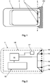
Fig.1 is a diagrammatic plan view of a motor vehicle in accordance with a first aspect of the invention having a rear closure member shown in a closed position; -
Fig.2 is a schematic representation of the motor vehicle shown inFig.1 showing a safety system forming part of the motor vehicle; -
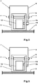
Fig.3 is a scrap side view of a hinge assembly forming part of a first embodiment of a mechanism forming part of the safety system shown inFig.2 showing the rear closure member in a latched open position; -
Fig.4 is a scrap side view similar toFig.3 but showing the rear closure member in a closed position; -
Fig.5 is a scrap view in the direction of arrow 'V' onFig.3 showing a solenoid actuated latch pin engaged with a rear closure member hinge member so as to hold the rear closure member in the open position; -
Fig.6 is a scrap view in the direction of arrow 'V' onFig.3 showing the solenoid actuated latch pin disengaged from rear closure member hinge member so as to allow the rear closure member to be moved in a closing direction from the open position; -
Fig.7 is a schematic drawing of a second embodiment of a mechanism that is intended to be a direct replacement for the mechanism shown inFigs.3 to 6 ; -
Fig.8 is a scrap view on the line Y-Y onFig.7 ; -
Fig.9 is a high level flow chart of a first embodiment of a method of controlling closing of a rear closure member; and -
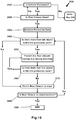
Fig.10 is a high level flow chart of a second embodiment of a method of controlling closing of a rear closure member. - With particular reference to
Figs. 1 and 2 there is shown amotor vehicle 1 having abody structure 2 to which is hingedly connected at a rear end thereof arear closure member 5. Therear closure member 5 is a manually moveable closure member meaning that opening and closing of therear closure member 5 is done manually. - The
rear closure member 5 is hingedly connected to thebody structure 2 near a top end by means of a pair of spaced aparthinge mechanisms 7 which facilitate opening and closing of therear closure member 5 about a substantially horizontal transverse pivot axis x-x. - The
motor vehicle 1 includes asafety system 10 the function of which is to reduce the risk of injury to persons not actively engaged in the closing of therear closure member 5 when therear closure member 5 is to be closed or, in some cases, is in the process of being closed. - The
safety system 10 comprises anelectronic controller 15 arranged to receive inputs from a number ofrear parking sensors 16, a rear closuremember state input 17 and is arranged to control the operation of an electronically controlledmechanism 12 used to prevent the closing of therear closure member 5 in certain circumstances. - The
rear parking sensors 16 provide an indication to the electronic controller of whether a person is within a predefined area to the rear of themotor vehicle 1 referred to herein as a protection zone PZ. The protection zone PZ is an area in which a person may accidentally be impacted against by therear closure member 5 during the process of closing of therear closure member 5 if a person closing therear closure member 5 is not aware of their presence. This can include a person close enough to the motor vehicle to lean in to a rear luggage compartment during the rear closure closing process to retrieve an item or a person who is so close to the rear of themotor vehicle 1 that closing of the rear closure member will likely produce contact between therear closure member 5 and that person. - The
electronic controller 15 is arranged to operate the electronically controlledmechanism 12 to prevent movement of therear closure member 5 in the closing direction in response to a feedback from therear parking sensors 16 when more than one object is located within the rear protection zone PZ of themotor vehicle 1 and therear closure member 5 is in the fully open position. That is to say, thesafety system 10 maintains therear closure member 5 in a fully open position if more than one object is sensed to be in the protection zone PZ. - The rear closure
member state input 17 is in the case of this example used to indicate to theelectronic controller 15 when therear closure member 5 is in the fully open and closed states. - In some embodiments the
safety system 10 is arranged to not only maintain therear closure member 5 in a fully open position if more than one object is sensed to be in the protection zone PZ when the rear closure is fully open but also to stop motion of therear closure member 5 in a closing direction if the number of objects in the protection zone increases to more than one during closing of therear closure member 5. - Referring now to
Figs.3 to 6 there is shown a first embodiment of an electronically controlledmechanism 12 to prevent movement of therear closure member 5 in the closing direction. - The electronically controlled
mechanism 12 is in the form of an electronically controlled latching mechanism comprising asolenoid actuator 18 having alatching pin 19 moveable into engagement with ahinge member 4 forming one half of one of thehinge mechanisms 7 used to hingedly connect therear closure member 5 to thestructural part 2 of themotor vehicle 1. Thesolenoid actuator 18 is operable in response to a control signal from theelectronic controller 15 to move thelatching pin 19 into engagement with thehinge member 4 when it is required to prevent movement of therear closure member 5 in a closing direction and therear closure member 5 is in a fully open position. - The hinge member is a
first hinge member 4 fastened to therear closure member 5 and the hinge mechanism also includes asecond hinge member 3 pivotally connected to thefirst hinge member 4 by ahinge pin 6. Thesecond hinge member 3 is fastened to part of thebody structure 2 of themotor vehicle 1. Thehinge pin 6 is coaxially aligned with the pivot axis x-x about which therear closure member 5 rotates during opening and closing. - The
solenoid actuator 18 is, in the case of this example, fastened to thesecond hinge member 3 but it will be appreciated that it could alternatively be fastened directly thebody structure 2 of themotor vehicle 1. In the case of this example thelatching pin 19 is biased by a spring (not shown) into an unlatched position as shown inFig.6 and moved by thesolenoid actuator 18 into engagement with thefirst hinge member 4 when it is required to prevent movement of therear closure member 5 in a closing direction which is when more than one object is sensed to be within the protection zone PZ and therear closure member 5 is in a fully open position as indicated by the rearclosure state input 17. - In the case of this example the
latching pin 19 is moved into engagement with anabutment surface 4a on thefirst hinge member 4 when it is required to prevent movement of therear closure member 5 in the closing direction but it will be appreciated that thelatching pin 19 could alternatively be engageable with an abutment member secured to thefirst hinge member 4 or be engageable with an aperture formed in thefirst hinge member 4. - It will also be appreciated that as an alternative to the foregoing the
solenoid actuator 18 could be mounted on thefirst hinge member 4 and thelatching pin 19 would then engage in some manner with thesecond hinge member 3 to prevent movement of therear closure member 5 from the fully open position when required. - It will also be appreciated that both of the
hinge mechanisms 7 used to hingedly connect therear closure member 5 to thebody structure 2 could be provided with such electronically controlled latching mechanisms to prevent movement of therear closure member 5 away from the fully open position when required. - In the case of this example, the
solenoid actuator 18 is only switched on to displace thelatching pin 19 into a latching position when there is more than one object (person) in the rear protection zone PZ and therear closure member 5 is in a fully open position. This is because it is only when therear closure member 5 is in the fully open position that thelatching pin 19 can engage with theabutment surface 4a on thefirst hinge member 4. That is to say, the arrangement of this example can only hold therear closure member 5 in the fully open position it cannot stop closing once it has started. - Referring now to
Figs.7 and 8 there is shown a second embodiment of an electronically controlledmechanism 12 to prevent movement of therear closure member 5 in the closing direction. - The electronically controlled
mechanism 12 is in this case in the form of an electronically controlled braking mechanism comprising apump 50 drivingly connected between first andsecond hinge members hinge mechanisms 7 used to hingedly connect therear closure member 5 to thebody structure 2 of themotor vehicle 1 and an electronically controlledvalve 48 to selectively prevent the flow of fluid such as oil from anoutlet 61 of thepump 60 to aninlet 62 of thepump 50 through arecirculation circuit 60 when it is required to prevent movement of therear closure member 5 in a closing direction which is when more than one object is sensed to be within the protection zone PZ. - The
first hinge member 44 is pivotally connected to thesecond hinge member 43 by apivot pin 49 arranged coaxially with respect to the transverse pivot axis x-x about which therear closure member 5 rotates between open and closed positions. Thesecond hinge member 3 is fastened to thebody structure 2 of themotor vehicle 1. - The
pump 50 has a rotor (not shown) connected to aninput shaft 53 that has agear wheel 52 fastened thereto that is drivingly connected toquadrant gear 51 fastened to thefirst hinge member 44. Thepump 50 is therefore connected to thefirst hinge member 44 by theinput shaft 53 and so, if theinput shaft 53 is prevented from rotation, therear closure member 5 that is fastened to thefirst hinge member 44 is also prevented from rotation thereby preventing movement of therear closure member 5. - The electronically controlled valve is in the form of a
solenoid valve 48 operatively controlled by theelectronic controller 15 that when closed prevents the flow of oil through therecirculation circuit 60 in the direction of the arrows "C" from theoutlet 61 to theinlet 62 when it is required to prevent movement of therear closure member 5 in the closing direction. A non-return valve "NRV" is arranged to bypass thesolenoid valve 48 to permit flow in a direction opposite to that shown by the arrows "C" through therecirculation circuit 60 even if thesolenoid valve 48 is closed. This allows therear closure member 5 to be moved from closed to open even if there is more than one object in the rear protection zone PZ. - Therefore, when the
solenoid valve 48 is closed, no oil can flow through therecirculation circuit 60 in the direction of the arrows "C" but flow in the opposite direction is possible through the non-return valve "NRV". Therefore rotation of aninput shaft 53 of thepump 50 is prevented when thesolenoid valve 48 is closed thereby preventing movement of therear closure member 5 in a rear closure closing direction but not movement in a rear closure opening direction. - It will be appreciated that instead of providing a non-return valve bypassing the
solenoid valve 48, theelectronic controller 15 could be arranged to only close thesolenoid valve 48 when there is more than one object in the rear protection zone PZ and therear closure member 5 is sensed to be moving in a closing direction. - One significant difference between this embodiment and the first embodiment is that the electronically controlled braking mechanism of this second embodiment can be used to prevent movement in the closing direction not only when the
rear closure member 5 is in the fully open position but also during closing of therear closure member 5. That is to say, if during the process of closing of therear closure member 5, more than one object is sensed to be within the protection zone PZ because, for example, a person has entered the protection zone PZ during the closing process, then theelectronic controller 15 can immediately close thesolenoid valve 48 thereby preventing further motion of therear closure member 5 in the closing direction. - It will be appreciated that it would be possible to by sensing the movement of the rear closure member at all times to switch-off the
solenoid valve 48 once therear closure member 5 has been closed more than a predefined amount. The predefined amount corresponds to a rear closure position where the risk of accidental injury to a third party is considered to be minimal. - It will be appreciated that both of the
hinge mechanisms 7 used to hingedly connect therear closure member 5 to thebody structure 2 could be provided with such electronically controlled braking mechanisms to prevent movement of therear closure member 5 in the closing direction when required. - It will be appreciated that other braking mechanisms could be used in a similar manner to the braking mechanism shown in
Figs. 7 and 8 . For example and without limitation, an electronically engageable clutch could be drivingly connected between the first and second hinge members and the electronic controller could be arranged to engage the clutch when it is required to prevent closing movement of the rear closure member. - As yet another example a double acting ram could be interposed between the body structure and the rear closure member and the flow of liquid from one end of the ram to an opposite end of the ram can be controlled by a solenoid valve that can be closed by an electronic controller when it is required to prevent closing movement of the rear closure member.
- With particular reference to
Fig.9 there is shown a first embodiment of a method of controlling closing of a rear closure member of a motor vehicle such as therear closure member 5 of themotor vehicle 1. - The
method 100 starts inbox 110 by checking whether the motor vehicle is stationary and if it is not no action is taken. That is to say, themethod 100 is only used when the motor vehicle is not moving. - If when checked in
box 110 the motor vehicle is determined to be stationary the method advances tobox 120 to check whether the rear closure member is fully open. If the rear closure member is not fully open then the method returns tobox 110 and will cycle aroundboxes method 100 only applies to a situation where the rear closure member is fully open and so is applicable to a safety system having a latching mechanism such as that shown inFigs. 3 to 6 where the rear closure member can only be prevented from closing from a fully open position. - Although not shown on
Fig.9 when the rear closure member is opened a rear protection zone is enabled by switching on rear parking sensors. - If it is determined in
box 120 that the rear closure member is fully open the method advances tobox 130. - In
box 130 it is checked whether there is more than one object in the protection zone. That is to say, it is checked whether there is more than one person located in a position where they could be impacted against by the rear closure member if the rear closure member is moved in a closing direction. - If it is determined in
box 130 that there is more than one object in the protection zone then the method advances tobox 140 where movement of the rear closure member away from the fully closed position is prevented that is to say a latching mechanism such as that shown in fFigs.3 to 6 is engaged to prevent movement of the rear closure member. - The method then returns from
box 140 tobox 130 to recheck whether there is still more than one object in the protection zone and, if there is, the method returns tobox 140 and will continue to cycle aroundboxes box 130 there is a finally a determination that there is no longer more than one object in the protection zone at which time the method advances tobox 150 where closing of the rear closure is permitted. Frombox 150 the method advances tobox 160 to check whether the rear closure member is still fully open and, if it is, will return tobox 130 and if it not will advance tobox 199 where it ends. - It will be appreciated that although in
box 150 it is permitted to close the rear closure member a user may no have actually started the closing process and so the rear closure member will remain fully open and hence the return frombox 160 tobox 130. - Returning to
box 130, if the answer to the test inbox 130 is 'No' the method advances tobox 150 where closing of the rear closure member is permitted because only one person is present and so there is no risk of injury to a third party. It will be appreciated if there are zero objects in the protection zone there is always no risk of injury because the rear closure member is manually operated and so cannot close without a person to close it. - From
box 150 the method advances tobox 160 to check whether the rear closure member is still fully open. If the rear closure member is still fully open the method returns tobox 130 and if the rear closure member is not still fully open it will advance tobox 199 where it ends. - Although not shown in
Fig.9 , it will be appreciated that if closing of the rear closure member is being prevented then a user of the motor vehicle may be provided with a warning of that fact. That is to saybox 140 may include not only a rear closure prevention action but also a user warning action. - With particular reference to
Fig.10 there is shown a second embodiment of a method of controlling closing of a rear closure member of a motor vehicle such as therear closure member 5 of themotor vehicle 1. - The
method 200 starts inbox 210 by checking whether the motor vehicle is stationary and, if it is not, advances tobox 199 where it ends. That is to say, themethod 200 is only used when the motor vehicle is not moving. - If when checked in
box 210 the motor vehicle is determined to be stationary then the method advances tobox 220 to check whether the rear closure member is fully open. - If the rear closure member is not fully open then the method returns to
box 210 and will cycle aroundboxes - When it is determined in
box 220 that the rear closure member is fully open the method will advance frombox 220 tobox 230. In box 230 a rear protection zone is activated by, for example, switching on rear parking sensors. - The method then advances from
box 230 tobox 240 where it is checked whether there is more than one object in the protection zone. That is to say, it is checked whether there is more than one person located in a position where they could be impacted against by the rear closure member if the rear closure member is moved in a closing direction. - If the answer to the test in
box 240 is 'No' the method advances tobox 270 where closing of the rear closure member is permitted because only one person is present and so there is no risk of injury to a third party. It will be appreciated if there are zero objects in the protection zone there is always no risk of injury because the rear closure member is manually operated and so closing of the rear closure member requires manual input from a person. - From
box 270 the method advances tobox 280 to check whether the rear closure member is closed and if it is not returns back tobox 240 and will continue to cycle through theboxes box 240 indicates that there is not more than one object in the protection zone until such time as it is determined inbox 280 that the rear closure member is in a closed position at which time the method advances tobox 299 where it ends. - Returning to
box 240 if it is determined that there is more than one object in the protection zone then the method advances tobox 250. Inbox 250 movement of the rear closure member in a closing direction is prevented. - From
box 250 the method then advances to check inbox 260 whether there is still more than one object in the protection zone and, if there is more than one object, the method returns tobox 250 and will continue to cycle aroundboxes box 260 that there is no longer more than one object in the protection zone at which time the method advances tobox 270 where closing of the rear closure member is permitted. - From
box 270 the method advances tobox 280 to check whether the rear closure member is closed and, if it is not, returns back tobox 240. - If when checking
box 240 there is not more than one object in the protection zone the method will proceed as before tobox 270 and, if when checked inbox 240, there is more than one object in the protection zone the will proceed as before tobox 250. - Finally when it is determined in
box 280 that the rear closure member is in a closed position themethod 200 advances tobox 299 where it ends. - Therefore in this case it is continuously checked whether there is more than one object in the protection zone during closing of the rear closure member and if the number of objects in the protection zone increases above one the method takes account of this and then prevents further closing movement of the rear closure member even after closing has started until the number of objects is no longer more than one.
- It will be appreciated that if at any time closing of the rear closure member is being prevented then a user of the motor vehicle may be provided with a warning of that fact. That is to say
box 250 may include both a movement preventing action and a user alerting action. - Therefore, in summary, whenever a rear closure member is in a fully open position the closing of the rear closure member is prevented if more than one object is sensed to be in a rear protection zone thereby reducing the risk of injury from occurring to a third person not actually closing the rear closure member.
- In some cases the electronically controlled mechanism used to prevent closing of the rear closure may be constructed such that it is able to stop closing after it has started as well as prevent movement from the fully open position.
- It will be appreciated that the electronically controlled mechanisms are exemplary in nature and not intended to represent production ready embodiments. Furthermore, the methods indicated in the two flow charts are only intended to represent two examples of how the invention can be put into effect.
- It will be appreciated by those skilled in the art that although the invention has been described by way of example with reference to one or more embodiments it is not limited to the disclosed embodiments and that alternative embodiments could be constructed without departing from the scope of the invention as defined by the appended claims.
Claims (14)
- A motor vehicle having a top hinged rear closure member manually moveable between open and closed positions, an electronically controlled mechanism to prevent, at least when the rear closure member is in a fully open position, movement of the rear closure member in a closing direction, an electronic controller to control the operation of the electronically controlled mechanism and a number of rear parking sensors to provide an indication to the electronic controller of whether one or more objects lies within a rear protection zone wherein, if the parking sensors indicate that more than one object is located within the rear protection zone, the electronic controller is arranged to operate the electronically controlled mechanism to prevent movement of the rear closure member in a closing direction.
- A motor vehicle as claimed in claim 1 wherein the electronic controller is arranged to operate the electronically controlled mechanism to prevent movement of the rear closure member in a closing direction only if the rear closure member is in a fully open position.
- A motor vehicle as claimed in claim 1 wherein the electronic controller is arranged to operate the electronically controlled mechanism to prevent movement of the rear closure member in a closing direction when the rear closure member is in a partially closed position.
- A motor vehicle as claimed in claim 1 or in claim 2 wherein the electronically controlled mechanism is an electronically controlled latching mechanism comprising a solenoid actuator having a latching pin moveable into engagement with a hinge member forming one half of a hinge mechanism used to hingedly connect the rear closure member to a structural part of the motor vehicle so as to prevent movement of the hinge member and the solenoid actuator is operable to move the latching pin into engagement with the hinge member when it is required to prevent movement of the rear closure member in a closing direction.
- A motor vehicle as claimed in claim 4 wherein the latching pin is moved into engagement with an abutment surface on the hinge member when it is required to prevent movement of the rear closure member in a closing direction.
- A motor vehicle as claimed in claim 4 or in claim 5 wherein the hinge member is a first hinge member fastened to the rear closure member and the hinge mechanism includes a second hinge member pivotally connected to the first hinge member and fastened to part of a body structure of the motor vehicle and the solenoid actuator is fastened to the second hinge member.
- A motor vehicle as claimed in claim 1 or in claim 3 wherein the electronically controlled mechanism comprises a pump drivingly connected between first and second hinge members forming a hinge mechanism used to hingedly connect the rear closure member to a body structure of the motor vehicle and an electronically controlled valve to prevent the flow of liquid from an outlet of the pump to an inlet of the pump through a recirculation circuit when it is required to prevent movement of the rear closure member in a closing direction.
- A motor vehicle as claimed in claim 7 wherein the first hinge member is a hinge member fastened to the rear closure member and the second hinge member is a hinge member pivotally connected to the first hinge member and fastened to the body structure of the motor vehicle.
- A motor vehicle as claimed in claim 8 wherein the pump is fastened to the second hinge member and has a drive shaft drivingly connected by a gear wheel to a quadrant gear fastened to the first hinge member.
- A method of controlling the closing motion of a manually operated top hinged rear closure member of a motor vehicle comprising checking whether more than one object is located within a rear protection zone of the motor vehicle and, at least when the rear closure member is in a fully open position, preventing movement of the rear closure member in a closing direction if more than one object is located within the rear protection zone.
- A method as claimed in claim 10 wherein the method further comprises stopping motion of the rear closure member in a closing direction if the number of objects in the protection zone increases to more than one during closing of the rear closure member.
- A method as claimed in claim 10 or in claim 11 wherein checking whether more than one object is located within a rear protection zone of the motor vehicle comprises using rear parking sensors to check for the presence of objects in the rear protection zone.
- A method as claimed in any of claims 10 to 12 wherein preventing movement of the rear closure member in a closing direction comprises using an electronically controlled mechanism to prevent movement in the closing direction.
- A method as claimed in claim 13 when dependent upon claim 12 wherein the method further comprises using an electronic controller to operate the electronically controlled mechanism to prevent movement in the closing direction in response to a feedback from the rear parking sensors.
Applications Claiming Priority (1)
| Application Number | Priority Date | Filing Date | Title |
|---|---|---|---|
| GB1710037.1A GB2563653B (en) | 2017-06-23 | 2017-06-23 | A Motor vehicle having a manual rear closure member |
Publications (2)
| Publication Number | Publication Date |
|---|---|
| EP3418481A1 true EP3418481A1 (en) | 2018-12-26 |
| EP3418481B1 EP3418481B1 (en) | 2019-07-24 |
Family
ID=59523516
Family Applications (1)
| Application Number | Title | Priority Date | Filing Date |
|---|---|---|---|
| EP18156063.2A Active EP3418481B1 (en) | 2017-06-23 | 2018-02-09 | A motor vehicle having a manual rear closure member |
Country Status (4)
| Country | Link |
|---|---|
| US (1) | US10871017B2 (en) |
| EP (1) | EP3418481B1 (en) |
| CN (1) | CN109113463B (en) |
| GB (1) | GB2563653B (en) |
Families Citing this family (3)
| Publication number | Priority date | Publication date | Assignee | Title |
|---|---|---|---|---|
| DE102018201832A1 (en) * | 2018-02-06 | 2019-08-08 | Brose Fahrzeugteile Gmbh & Co. Kommanditgesellschaft, Bamberg | Door of a motor vehicle |
| JP7298213B2 (en) * | 2019-03-15 | 2023-06-27 | 株式会社アイシン | Vehicle opening/closing body control device |
| US11847833B2 (en) | 2020-02-12 | 2023-12-19 | Strattec Security Corporation | Broad coverage non-contact obstacle detection |
Citations (3)
| Publication number | Priority date | Publication date | Assignee | Title |
|---|---|---|---|---|
| DE10132886A1 (en) * | 2001-07-06 | 2003-01-16 | Bosch Gmbh Robert | Method and device for opening and closing a part rotatably or tiltably mounted on the vehicle |
| US20040040771A1 (en) * | 2002-09-04 | 2004-03-04 | Siemens Vdo Automotive Corporation | Liftgate anti-pinch detector utilizing back-up sensors |
| DE102005033098A1 (en) * | 2005-07-15 | 2007-01-25 | Stabilus Gmbh | Tailgate for a vehicle comprises flaps which pivot about an axle and a coupling device for connecting the two flaps |
Family Cites Families (27)
| Publication number | Priority date | Publication date | Assignee | Title |
|---|---|---|---|---|
| US5408726A (en) * | 1993-06-21 | 1995-04-25 | Kent; Erma W. | Locking device for locking a closure in an open position |
| DE19613178A1 (en) * | 1996-04-02 | 1997-10-09 | Heinrich Landert | Method for operating a door system and a door system operating according to the method |
| US5774938A (en) * | 1997-02-19 | 1998-07-07 | Erma W. Kent | Locking device for locking a closure in an open position |
| GB9813166D0 (en) * | 1998-06-19 | 1998-08-19 | Rover Group | Motor vehicle door assembly |
| DE19829731A1 (en) * | 1998-07-03 | 2000-01-05 | Mannesmann Vdo Ag | Motor vehicle with tailgate |
| DE19853344A1 (en) * | 1998-11-19 | 2000-05-25 | Volkswagen Ag | Automatic door opening system |
| US6321488B1 (en) * | 1999-03-05 | 2001-11-27 | Atoma International Corp. | Power sliding vehicle door |
| US6744365B2 (en) * | 2000-01-21 | 2004-06-01 | Rosario G. Sicuranza | Vehicle door stop safety system |
| US9151692B2 (en) * | 2002-06-11 | 2015-10-06 | Intelligent Technologies International, Inc. | Asset monitoring system using multiple imagers |
| JP4267996B2 (en) * | 2003-09-17 | 2009-05-27 | Thk株式会社 | Automatic door device |
| JP2006328853A (en) * | 2005-05-27 | 2006-12-07 | Nabtesco Corp | Compound sensor for door and automatic door system |
| DE102006051745B4 (en) * | 2006-09-28 | 2024-02-08 | OSRAM Opto Semiconductors Gesellschaft mit beschränkter Haftung | LED semiconductor body and use of an LED semiconductor body |
| US8104823B2 (en) * | 2007-06-15 | 2012-01-31 | Ford Global Technologies | Automotive door with hydraulically locking repositionable immobilizer |
| DE202009018205U1 (en) * | 2009-06-02 | 2011-05-05 | Volkswagen Ag | Device for actuating a closing element of a vehicle |
| GB2505682B (en) * | 2012-09-06 | 2015-10-14 | Jaguar Land Rover Ltd | A system for controlling the doors of a power split tailgate |
| US9068390B2 (en) * | 2013-01-21 | 2015-06-30 | Magna Electronics Inc. | Vehicle hatch control system |
| GB2515099B (en) * | 2013-06-14 | 2015-11-11 | Jaguar Land Rover Ltd | Door protection system |
| WO2015023698A1 (en) * | 2013-08-13 | 2015-02-19 | FlatZen, Inc. | Hinge mechanisms and foldable furniture |
| KR102128756B1 (en) * | 2014-02-17 | 2020-07-01 | 엘지이노텍 주식회사 | Apparatus and method for opening trunk of vehicle, and recording medium for recording program performing the method |
| JP6618684B2 (en) * | 2015-01-08 | 2019-12-11 | ローム株式会社 | Ultrasonic sensor and burst signal control method |
| RU2698593C2 (en) * | 2015-04-17 | 2019-08-28 | ФОРД ГЛОУБАЛ ТЕКНОЛОДЖИЗ, ЭлЭлСи | Adjustable lock assembly for vehicle closing element (versions) and vehicle closing element assembly (versions) |
| US20160314362A1 (en) * | 2015-04-22 | 2016-10-27 | Ford Global Technologies, Llc | Depth mapping camera for door inside |
| US20170030118A1 (en) * | 2015-07-29 | 2017-02-02 | Ford Global Technologies, Llc | Door closure and latching confirmation system |
| EP3344837A1 (en) * | 2015-09-03 | 2018-07-11 | Faraday & Future Inc. | System and method for opening and closing vehicle door |
| JP6649036B2 (en) * | 2015-10-22 | 2020-02-19 | 株式会社ユーシン | Door opening and closing device |
| US9834175B2 (en) * | 2015-10-22 | 2017-12-05 | U-Shin Ltd. | Door opening and closing device |
| US11124113B2 (en) * | 2017-04-18 | 2021-09-21 | Magna Electronics Inc. | Vehicle hatch clearance determining system |
-
2017
- 2017-06-23 GB GB1710037.1A patent/GB2563653B/en not_active Expired - Fee Related
-
2018
- 2018-02-09 EP EP18156063.2A patent/EP3418481B1/en active Active
- 2018-04-20 US US15/958,353 patent/US10871017B2/en active Active
- 2018-06-19 CN CN201810630891.7A patent/CN109113463B/en active Active
Patent Citations (3)
| Publication number | Priority date | Publication date | Assignee | Title |
|---|---|---|---|---|
| DE10132886A1 (en) * | 2001-07-06 | 2003-01-16 | Bosch Gmbh Robert | Method and device for opening and closing a part rotatably or tiltably mounted on the vehicle |
| US20040040771A1 (en) * | 2002-09-04 | 2004-03-04 | Siemens Vdo Automotive Corporation | Liftgate anti-pinch detector utilizing back-up sensors |
| DE102005033098A1 (en) * | 2005-07-15 | 2007-01-25 | Stabilus Gmbh | Tailgate for a vehicle comprises flaps which pivot about an axle and a coupling device for connecting the two flaps |
Also Published As
| Publication number | Publication date |
|---|---|
| EP3418481B1 (en) | 2019-07-24 |
| GB2563653B (en) | 2022-02-09 |
| US20180371812A1 (en) | 2018-12-27 |
| GB2563653A (en) | 2018-12-26 |
| GB201710037D0 (en) | 2017-08-09 |
| CN109113463A (en) | 2019-01-01 |
| US10871017B2 (en) | 2020-12-22 |
| CN109113463B (en) | 2026-01-09 |
Similar Documents
| Publication | Publication Date | Title |
|---|---|---|
| US10415295B2 (en) | Vehicle closure member power actuator control | |
| CN110573688B (en) | lock for motor vehicle | |
| US8506002B2 (en) | Intuitive control system for power assisted vehicle doors | |
| EP3418481B1 (en) | A motor vehicle having a manual rear closure member | |
| EP2583848B1 (en) | Dual hinged vehicle door and method of controlling same | |
| US20160002959A1 (en) | Proactive safety methods, devices and systems, and safety methods and devices for blocking operation of latches for occupant ingress and egress closure panels | |
| US10280653B2 (en) | Vehicle door latch with electronic override | |
| US7357435B2 (en) | Power tailgate anti-theft system | |
| KR20120069586A (en) | Method for operating a hatch arrangement of a motor vehicle | |
| KR102206751B1 (en) | Rear wing door and lower door automatic up and down switchgear of the truck | |
| EP2578426B1 (en) | Vehicle with openable closure | |
| US6588151B1 (en) | Power closure control apparatus | |
| CN117005769A (en) | Actuation system for closing panels including pop-up safety system for hinges | |
| JP5669750B2 (en) | Control method for closing operation of vehicle wing and corresponding vehicle closing system | |
| US20250297500A1 (en) | Device for Fully Electrical Opening of a Vehicle Flap | |
| EP1388633A1 (en) | Device for detecting the aera surrounding a vehicle and device to open doors of a vehicle | |
| CN103670083B (en) | Closure device for compartment which can be closed by flap in motor vehicle | |
| US9945161B2 (en) | Lock system for dual vehicle closures | |
| GB2302559A (en) | Opening closure members | |
| WO2016025050A1 (en) | Automotive door hinge safety lock | |
| GB2562273A (en) | A control system for a vehicle bonnet closure-release system | |
| GB2562271A (en) | A control system for a vehicle bonnet release system | |
| KR101758738B1 (en) | System for closing and opening door of container for vehicle | |
| US12366096B2 (en) | Operation logic for a power hood system | |
| JP2014145226A (en) | Device for opening/closing opening/closing body |
Legal Events
| Date | Code | Title | Description |
|---|---|---|---|
| PUAI | Public reference made under article 153(3) epc to a published international application that has entered the european phase |
Free format text: ORIGINAL CODE: 0009012 |
|
| STAA | Information on the status of an ep patent application or granted ep patent |
Free format text: STATUS: REQUEST FOR EXAMINATION WAS MADE |
|
| 17P | Request for examination filed |
Effective date: 20180919 |
|
| AK | Designated contracting states |
Kind code of ref document: A1 Designated state(s): AL AT BE BG CH CY CZ DE DK EE ES FI FR GB GR HR HU IE IS IT LI LT LU LV MC MK MT NL NO PL PT RO RS SE SI SK SM TR |
|
| AX | Request for extension of the european patent |
Extension state: BA ME |
|
| GRAP | Despatch of communication of intention to grant a patent |
Free format text: ORIGINAL CODE: EPIDOSNIGR1 |
|
| STAA | Information on the status of an ep patent application or granted ep patent |
Free format text: STATUS: GRANT OF PATENT IS INTENDED |
|
| RIC1 | Information provided on ipc code assigned before grant |
Ipc: E05F 5/00 20170101AFI20190315BHEP Ipc: E05F 15/40 20150101ALI20190315BHEP Ipc: E05D 3/02 20060101ALN20190315BHEP Ipc: E05D 11/10 20060101ALI20190315BHEP Ipc: B60J 5/10 20060101ALI20190315BHEP Ipc: G01S 15/93 20060101ALN20190315BHEP Ipc: E05F 15/43 20150101ALI20190315BHEP |
|
| INTG | Intention to grant announced |
Effective date: 20190412 |
|
| RIC1 | Information provided on ipc code assigned before grant |
Ipc: B60J 5/10 20060101ALI20190401BHEP Ipc: G01S 15/93 20060101ALN20190401BHEP Ipc: E05F 5/00 20170101AFI20190401BHEP Ipc: E05D 11/10 20060101ALI20190401BHEP Ipc: E05D 3/02 20060101ALN20190401BHEP Ipc: E05F 15/40 20150101ALI20190401BHEP Ipc: E05F 15/43 20150101ALI20190401BHEP |
|
| GRAA | (expected) grant |
Free format text: ORIGINAL CODE: 0009210 |
|
| STAA | Information on the status of an ep patent application or granted ep patent |
Free format text: STATUS: THE PATENT HAS BEEN GRANTED |
|
| AK | Designated contracting states |
Kind code of ref document: B1 Designated state(s): AL AT BE BG CH CY CZ DE DK EE ES FI FR GB GR HR HU IE IS IT LI LT LU LV MC MK MT NL NO PL PT RO RS SE SI SK SM TR |
|
| REG | Reference to a national code |
Ref country code: GB Ref legal event code: FG4D |
|
| REG | Reference to a national code |
Ref country code: CH Ref legal event code: EP |
|
| REG | Reference to a national code |
Ref country code: DE Ref legal event code: R096 Ref document number: 602018000281 Country of ref document: DE |
|
| REG | Reference to a national code |
Ref country code: AT Ref legal event code: REF Ref document number: 1158388 Country of ref document: AT Kind code of ref document: T Effective date: 20190815 |
|
| REG | Reference to a national code |
Ref country code: IE Ref legal event code: FG4D |
|
| REG | Reference to a national code |
Ref country code: NL Ref legal event code: MP Effective date: 20190724 |
|
| REG | Reference to a national code |
Ref country code: LT Ref legal event code: MG4D |
|
| REG | Reference to a national code |
Ref country code: AT Ref legal event code: MK05 Ref document number: 1158388 Country of ref document: AT Kind code of ref document: T Effective date: 20190724 |
|
| PG25 | Lapsed in a contracting state [announced via postgrant information from national office to epo] |
Ref country code: FI Free format text: LAPSE BECAUSE OF FAILURE TO SUBMIT A TRANSLATION OF THE DESCRIPTION OR TO PAY THE FEE WITHIN THE PRESCRIBED TIME-LIMIT Effective date: 20190724 Ref country code: HR Free format text: LAPSE BECAUSE OF FAILURE TO SUBMIT A TRANSLATION OF THE DESCRIPTION OR TO PAY THE FEE WITHIN THE PRESCRIBED TIME-LIMIT Effective date: 20190724 Ref country code: SE Free format text: LAPSE BECAUSE OF FAILURE TO SUBMIT A TRANSLATION OF THE DESCRIPTION OR TO PAY THE FEE WITHIN THE PRESCRIBED TIME-LIMIT Effective date: 20190724 Ref country code: AT Free format text: LAPSE BECAUSE OF FAILURE TO SUBMIT A TRANSLATION OF THE DESCRIPTION OR TO PAY THE FEE WITHIN THE PRESCRIBED TIME-LIMIT Effective date: 20190724 Ref country code: NO Free format text: LAPSE BECAUSE OF FAILURE TO SUBMIT A TRANSLATION OF THE DESCRIPTION OR TO PAY THE FEE WITHIN THE PRESCRIBED TIME-LIMIT Effective date: 20191024 Ref country code: PT Free format text: LAPSE BECAUSE OF FAILURE TO SUBMIT A TRANSLATION OF THE DESCRIPTION OR TO PAY THE FEE WITHIN THE PRESCRIBED TIME-LIMIT Effective date: 20191125 Ref country code: LT Free format text: LAPSE BECAUSE OF FAILURE TO SUBMIT A TRANSLATION OF THE DESCRIPTION OR TO PAY THE FEE WITHIN THE PRESCRIBED TIME-LIMIT Effective date: 20190724 Ref country code: BG Free format text: LAPSE BECAUSE OF FAILURE TO SUBMIT A TRANSLATION OF THE DESCRIPTION OR TO PAY THE FEE WITHIN THE PRESCRIBED TIME-LIMIT Effective date: 20191024 Ref country code: NL Free format text: LAPSE BECAUSE OF FAILURE TO SUBMIT A TRANSLATION OF THE DESCRIPTION OR TO PAY THE FEE WITHIN THE PRESCRIBED TIME-LIMIT Effective date: 20190724 |
|
| PG25 | Lapsed in a contracting state [announced via postgrant information from national office to epo] |
Ref country code: ES Free format text: LAPSE BECAUSE OF FAILURE TO SUBMIT A TRANSLATION OF THE DESCRIPTION OR TO PAY THE FEE WITHIN THE PRESCRIBED TIME-LIMIT Effective date: 20190724 Ref country code: AL Free format text: LAPSE BECAUSE OF FAILURE TO SUBMIT A TRANSLATION OF THE DESCRIPTION OR TO PAY THE FEE WITHIN THE PRESCRIBED TIME-LIMIT Effective date: 20190724 Ref country code: GR Free format text: LAPSE BECAUSE OF FAILURE TO SUBMIT A TRANSLATION OF THE DESCRIPTION OR TO PAY THE FEE WITHIN THE PRESCRIBED TIME-LIMIT Effective date: 20191025 Ref country code: IS Free format text: LAPSE BECAUSE OF FAILURE TO SUBMIT A TRANSLATION OF THE DESCRIPTION OR TO PAY THE FEE WITHIN THE PRESCRIBED TIME-LIMIT Effective date: 20191124 Ref country code: RS Free format text: LAPSE BECAUSE OF FAILURE TO SUBMIT A TRANSLATION OF THE DESCRIPTION OR TO PAY THE FEE WITHIN THE PRESCRIBED TIME-LIMIT Effective date: 20190724 Ref country code: LV Free format text: LAPSE BECAUSE OF FAILURE TO SUBMIT A TRANSLATION OF THE DESCRIPTION OR TO PAY THE FEE WITHIN THE PRESCRIBED TIME-LIMIT Effective date: 20190724 |
|
| PG25 | Lapsed in a contracting state [announced via postgrant information from national office to epo] |
Ref country code: TR Free format text: LAPSE BECAUSE OF FAILURE TO SUBMIT A TRANSLATION OF THE DESCRIPTION OR TO PAY THE FEE WITHIN THE PRESCRIBED TIME-LIMIT Effective date: 20190724 |
|
| PG25 | Lapsed in a contracting state [announced via postgrant information from national office to epo] |
Ref country code: PL Free format text: LAPSE BECAUSE OF FAILURE TO SUBMIT A TRANSLATION OF THE DESCRIPTION OR TO PAY THE FEE WITHIN THE PRESCRIBED TIME-LIMIT Effective date: 20190724 Ref country code: EE Free format text: LAPSE BECAUSE OF FAILURE TO SUBMIT A TRANSLATION OF THE DESCRIPTION OR TO PAY THE FEE WITHIN THE PRESCRIBED TIME-LIMIT Effective date: 20190724 Ref country code: RO Free format text: LAPSE BECAUSE OF FAILURE TO SUBMIT A TRANSLATION OF THE DESCRIPTION OR TO PAY THE FEE WITHIN THE PRESCRIBED TIME-LIMIT Effective date: 20190724 Ref country code: IT Free format text: LAPSE BECAUSE OF FAILURE TO SUBMIT A TRANSLATION OF THE DESCRIPTION OR TO PAY THE FEE WITHIN THE PRESCRIBED TIME-LIMIT Effective date: 20190724 Ref country code: DK Free format text: LAPSE BECAUSE OF FAILURE TO SUBMIT A TRANSLATION OF THE DESCRIPTION OR TO PAY THE FEE WITHIN THE PRESCRIBED TIME-LIMIT Effective date: 20190724 |
|
| PG25 | Lapsed in a contracting state [announced via postgrant information from national office to epo] |
Ref country code: SK Free format text: LAPSE BECAUSE OF FAILURE TO SUBMIT A TRANSLATION OF THE DESCRIPTION OR TO PAY THE FEE WITHIN THE PRESCRIBED TIME-LIMIT Effective date: 20190724 Ref country code: CZ Free format text: LAPSE BECAUSE OF FAILURE TO SUBMIT A TRANSLATION OF THE DESCRIPTION OR TO PAY THE FEE WITHIN THE PRESCRIBED TIME-LIMIT Effective date: 20190724 Ref country code: IS Free format text: LAPSE BECAUSE OF FAILURE TO SUBMIT A TRANSLATION OF THE DESCRIPTION OR TO PAY THE FEE WITHIN THE PRESCRIBED TIME-LIMIT Effective date: 20200224 Ref country code: SM Free format text: LAPSE BECAUSE OF FAILURE TO SUBMIT A TRANSLATION OF THE DESCRIPTION OR TO PAY THE FEE WITHIN THE PRESCRIBED TIME-LIMIT Effective date: 20190724 |
|
| REG | Reference to a national code |
Ref country code: DE Ref legal event code: R097 Ref document number: 602018000281 Country of ref document: DE |
|
| PLBE | No opposition filed within time limit |
Free format text: ORIGINAL CODE: 0009261 |
|
| STAA | Information on the status of an ep patent application or granted ep patent |
Free format text: STATUS: NO OPPOSITION FILED WITHIN TIME LIMIT |
|
| PG2D | Information on lapse in contracting state deleted |
Ref country code: IS |
|
| 26N | No opposition filed |
Effective date: 20200603 |
|
| REG | Reference to a national code |
Ref country code: BE Ref legal event code: MM Effective date: 20200229 |
|
| PG25 | Lapsed in a contracting state [announced via postgrant information from national office to epo] |
Ref country code: MC Free format text: LAPSE BECAUSE OF FAILURE TO SUBMIT A TRANSLATION OF THE DESCRIPTION OR TO PAY THE FEE WITHIN THE PRESCRIBED TIME-LIMIT Effective date: 20190724 Ref country code: LU Free format text: LAPSE BECAUSE OF NON-PAYMENT OF DUE FEES Effective date: 20200209 |
|
| REG | Reference to a national code |
Ref country code: DE Ref legal event code: R082 Ref document number: 602018000281 Country of ref document: DE Representative=s name: HL KEMPNER PATENTANWAELTE, SOLICITORS (ENGLAND, DE Ref country code: DE Ref legal event code: R082 Ref document number: 602018000281 Country of ref document: DE Representative=s name: HL KEMPNER PATENTANWALT, RECHTSANWALT, SOLICIT, DE Ref country code: DE Ref legal event code: R082 Ref document number: 602018000281 Country of ref document: DE Representative=s name: HL KEMPNER PARTG MBB, DE |
|
| PG25 | Lapsed in a contracting state [announced via postgrant information from national office to epo] |
Ref country code: FR Free format text: LAPSE BECAUSE OF NON-PAYMENT OF DUE FEES Effective date: 20200229 Ref country code: IE Free format text: LAPSE BECAUSE OF NON-PAYMENT OF DUE FEES Effective date: 20200209 |
|
| PG25 | Lapsed in a contracting state [announced via postgrant information from national office to epo] |
Ref country code: BE Free format text: LAPSE BECAUSE OF NON-PAYMENT OF DUE FEES Effective date: 20200229 |
|
| PG25 | Lapsed in a contracting state [announced via postgrant information from national office to epo] |
Ref country code: CH Free format text: LAPSE BECAUSE OF NON-PAYMENT OF DUE FEES Effective date: 20210228 Ref country code: LI Free format text: LAPSE BECAUSE OF NON-PAYMENT OF DUE FEES Effective date: 20210228 |
|
| PG25 | Lapsed in a contracting state [announced via postgrant information from national office to epo] |
Ref country code: MT Free format text: LAPSE BECAUSE OF FAILURE TO SUBMIT A TRANSLATION OF THE DESCRIPTION OR TO PAY THE FEE WITHIN THE PRESCRIBED TIME-LIMIT Effective date: 20190724 Ref country code: CY Free format text: LAPSE BECAUSE OF FAILURE TO SUBMIT A TRANSLATION OF THE DESCRIPTION OR TO PAY THE FEE WITHIN THE PRESCRIBED TIME-LIMIT Effective date: 20190724 |
|
| PG25 | Lapsed in a contracting state [announced via postgrant information from national office to epo] |
Ref country code: MK Free format text: LAPSE BECAUSE OF FAILURE TO SUBMIT A TRANSLATION OF THE DESCRIPTION OR TO PAY THE FEE WITHIN THE PRESCRIBED TIME-LIMIT Effective date: 20190724 |
|
| GBPC | Gb: european patent ceased through non-payment of renewal fee |
Effective date: 20220209 |
|
| PG25 | Lapsed in a contracting state [announced via postgrant information from national office to epo] |
Ref country code: GB Free format text: LAPSE BECAUSE OF NON-PAYMENT OF DUE FEES Effective date: 20220209 |
|
| P01 | Opt-out of the competence of the unified patent court (upc) registered |
Effective date: 20230620 |
|
| PG25 | Lapsed in a contracting state [announced via postgrant information from national office to epo] |
Ref country code: SI Free format text: LAPSE BECAUSE OF FAILURE TO SUBMIT A TRANSLATION OF THE DESCRIPTION OR TO PAY THE FEE WITHIN THE PRESCRIBED TIME-LIMIT Effective date: 20190724 |
|
| PGFP | Annual fee paid to national office [announced via postgrant information from national office to epo] |
Ref country code: DE Payment date: 20240109 Year of fee payment: 7 |
|
| REG | Reference to a national code |
Ref country code: DE Ref legal event code: R119 Ref document number: 602018000281 Country of ref document: DE |
|
| PG25 | Lapsed in a contracting state [announced via postgrant information from national office to epo] |
Ref country code: DE Free format text: LAPSE BECAUSE OF NON-PAYMENT OF DUE FEES Effective date: 20250902 |