EP3418224A1 - Conveyor device - Google Patents
Conveyor device Download PDFInfo
- Publication number
- EP3418224A1 EP3418224A1 EP17753121.7A EP17753121A EP3418224A1 EP 3418224 A1 EP3418224 A1 EP 3418224A1 EP 17753121 A EP17753121 A EP 17753121A EP 3418224 A1 EP3418224 A1 EP 3418224A1
- Authority
- EP
- European Patent Office
- Prior art keywords
- contact part
- infilling
- plate
- support
- tray
- Prior art date
- Legal status (The legal status is an assumption and is not a legal conclusion. Google has not performed a legal analysis and makes no representation as to the accuracy of the status listed.)
- Granted
Links
Images


Classifications
-
- B—PERFORMING OPERATIONS; TRANSPORTING
- B65—CONVEYING; PACKING; STORING; HANDLING THIN OR FILAMENTARY MATERIAL
- B65G—TRANSPORT OR STORAGE DEVICES, e.g. CONVEYORS FOR LOADING OR TIPPING, SHOP CONVEYOR SYSTEMS OR PNEUMATIC TUBE CONVEYORS
- B65G17/00—Conveyors having an endless traction element, e.g. a chain, transmitting movement to a continuous or substantially-continuous load-carrying surface or to a series of individual load-carriers; Endless-chain conveyors in which the chains form the load-carrying surface
- B65G17/06—Conveyors having an endless traction element, e.g. a chain, transmitting movement to a continuous or substantially-continuous load-carrying surface or to a series of individual load-carriers; Endless-chain conveyors in which the chains form the load-carrying surface having a load-carrying surface formed by a series of interconnected, e.g. longitudinal, links, plates, or platforms
- B65G17/065—Conveyors having an endless traction element, e.g. a chain, transmitting movement to a continuous or substantially-continuous load-carrying surface or to a series of individual load-carriers; Endless-chain conveyors in which the chains form the load-carrying surface having a load-carrying surface formed by a series of interconnected, e.g. longitudinal, links, plates, or platforms the load carrying surface being formed by plates or platforms attached to a single traction element
- B65G17/066—Conveyors having an endless traction element, e.g. a chain, transmitting movement to a continuous or substantially-continuous load-carrying surface or to a series of individual load-carriers; Endless-chain conveyors in which the chains form the load-carrying surface having a load-carrying surface formed by a series of interconnected, e.g. longitudinal, links, plates, or platforms the load carrying surface being formed by plates or platforms attached to a single traction element specially adapted to follow a curved path
-
- B—PERFORMING OPERATIONS; TRANSPORTING
- B65—CONVEYING; PACKING; STORING; HANDLING THIN OR FILAMENTARY MATERIAL
- B65G—TRANSPORT OR STORAGE DEVICES, e.g. CONVEYORS FOR LOADING OR TIPPING, SHOP CONVEYOR SYSTEMS OR PNEUMATIC TUBE CONVEYORS
- B65G17/00—Conveyors having an endless traction element, e.g. a chain, transmitting movement to a continuous or substantially-continuous load-carrying surface or to a series of individual load-carriers; Endless-chain conveyors in which the chains form the load-carrying surface
- B65G17/30—Details; Auxiliary devices
- B65G17/32—Individual load-carriers
-
- B—PERFORMING OPERATIONS; TRANSPORTING
- B65—CONVEYING; PACKING; STORING; HANDLING THIN OR FILAMENTARY MATERIAL
- B65G—TRANSPORT OR STORAGE DEVICES, e.g. CONVEYORS FOR LOADING OR TIPPING, SHOP CONVEYOR SYSTEMS OR PNEUMATIC TUBE CONVEYORS
- B65G47/00—Article or material-handling devices associated with conveyors; Methods employing such devices
- B65G47/34—Devices for discharging articles or materials from conveyor
- B65G47/38—Devices for discharging articles or materials from conveyor by dumping, tripping, or releasing load carriers
-
- B—PERFORMING OPERATIONS; TRANSPORTING
- B65—CONVEYING; PACKING; STORING; HANDLING THIN OR FILAMENTARY MATERIAL
- B65G—TRANSPORT OR STORAGE DEVICES, e.g. CONVEYORS FOR LOADING OR TIPPING, SHOP CONVEYOR SYSTEMS OR PNEUMATIC TUBE CONVEYORS
- B65G47/00—Article or material-handling devices associated with conveyors; Methods employing such devices
- B65G47/74—Feeding, transfer, or discharging devices of particular kinds or types
- B65G47/94—Devices for flexing or tilting travelling structures; Throw-off carriages
- B65G47/96—Devices for tilting links or platform
- B65G47/962—Devices for tilting links or platform tilting about an axis substantially parallel to the conveying direction
Definitions
- the present invention relates to a conveyor apparatus for transporting articles, and particularly relates to a conveyor apparatus for transporting articles placed on article supports such as a tray.
- Conveyor apparatuses are used in some facilities where a plurality of articles need to be conveyed from an origin to destinations, for example, in the case of an airport where passenger's baggage is conveyed from an airport check-in area to an area for loading the baggage into an airplane that is scheduled to board passengers.
- a conveyor apparatus conveys articles on trays (article supports) traveling on a conveying path and inclines the trays at positions for the placed articles (inclines the trays laterally with respect to the conveying direction), so that the articles are discharged into chutes disposed along the conveying path and connected to the destinations.
- a clearance is left between the adjacent article supports, that is, between the trays, so that part (e.g., the shoulder strap of a bag) of baggage (article) may be dropped or caught in the clearance.
- a cover member for covering a clearance (gap) may be prepared.
- a cover member described in Patent Literature 1 is directly connected to the bottom of an article support member (tray) via a pivot or a pin and thus the cover member is inclined with the article support member being inclined.
- Patent Literature 1 WO00/02802
- the cover member described in Patent Literature 1 is directly connected to the article support member at the center of the cover member in the width direction (a direction crossing the conveying direction).
- the weight of the cover member is supported only at the center of the cover member in the width direction.
- the weight of one end of the cover member in the width direction is not supported and thus after an extended period of use in this state, one end of the cover member may curve downward because of the weight of the cover member.
- the article support member inclines, one end of the cover member in the width direction is pressed from the article support member. This press also may curve downward one end of the cover member in the width direction.
- Patent Literature 1 also describes a method of supporting the cover member by means of a support element reinforced with a rib, as a supporting method of the cover member.
- this method also requires the support element in addition to the cover member, as a structure for filling a clearance between the article support members. This increases the number of components and the cost of constructing conveyor equipment. If a rib is additionally mounted on the cover member by welding in the absence of the support element, heat for welding may warp the cover member toward the mounting surface of the rib, that is, the underside of the cover member, causing a difference in shape between the cover member and the article support member. This leaves a clearance between the cover member and the article support member.
- An object of the present invention is to provide a conveyor apparatus that prevents a clearance from being vertically left between an article support and one end of an infilling member in the width direction while suppressing the cost of constructing conveyor equipment without the need for a support element, the infilling member filling a gap between the article supports arranged on a conveying path.
- a conveyor apparatus for conveying articles, including: a plurality of traveling units that travel in series along a conveying path for the articles; and a plurality of article supports that have article support surfaces for supporting the articles and that are caused to travel on the conveying path by the respective traveling units, the conveyor apparatus further including infilling members provided for the respective article ' supports, the infilling member filling a clearance between the article supports longitudinally adjacent to each other in the conveying path, in which the article support has a support contact part on the rear end along the conveying path, the infilling member has an infilling contact part on the front end along the conveying path, the infilling contact part being in contact with the support contact part, and the infilling contact part has a larger curvature than the support contact part.
- the conveyor apparatus may further include an urging member that urges the infilling contact part of the infilling member to the support contact part of the article support, in which the infilling contact part is made of a flexible material, and the infilling contact part may be urged to the support contact part by the urging member so as to come into contact with the support contact part while being bent along the shape of the support contact part.
- the urging member urges the infilling contact part to the support contact part so as to shape the infilling contact part along the support contact part, thereby completely filling a clearance between the infilling contact part and the support contact part.
- the conveyor apparatus may be configured such that the infilling contact part of the infilling member is made of an elastic material and the infilling contact part may be brought into contact with the support contact part by the elasticity of the infilling contact part while being bent along the shape of the support contact part of the article support.
- the infilling contact part is shaped along the shape of the support contact part by the elasticity of the infilling contact part, thereby completely filling a clearance between the infilling contact part and the support contact part.
- the infilling member may be formed such that the curvature of the infilling contact part of the infilling member increases toward one end of the infilling member.
- the curvature of the infilling contact part increases toward the vicinity of one end of the infilling member that is likely to curve downward.
- a clearance between the infilling contact part and the support contact part is kept closed.
- one end of the infilling contact part may receive a larger load than a part around the center.
- a curvature on one end is larger than that of a part around the center, thereby keeping the infilling contact part and the support contact part in close contact with each other.
- a clearance between the article supports is filled with the infilling member and a clearance is prevented from being left between the infilling member and the article support even if both ends of the infilling member in the width direction are curved downward by the weight of the infilling member after an extended period of use of the infilling member.
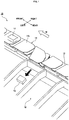
- FIG. 1 shows a part of a conveyor apparatus 10 as an example of an embodiment of the present invention.
- an article 12 to be conveyed is placed on a tray 14 serving as an article support and is conveyed in a conveying direction W.
- a direction along the conveying direction W is referred to as a longitudinal direction and a direction crossing the conveying direction W is referred to as a lateral direction or a width direction.
- the longitudinal and lateral directions are determined as indicated by arrows in FIG. 1 .
- the trays 14 are arranged in series along the conveying direction W. Each of the trays 14 can support the article 12 on an article support surface 14a. As shown in FIG.
- the top surface of the tray 14 is curved slightly upward.
- the article 12 is moved by the weight of the article 12 to the center of the tray 14 in the width direction along the curve of the top surface of the tray 14. This prevents the article 12 from laterally falling in the width direction of the tray 14, thereby stably supporting the article 12 at the center of the tray 14 in the width direction.
- the tray 14 can be laterally inclined with respect to the conveying direction W ( FIG. 1 only shows a tray 14 inclined to the left).
- the article support surface 14a of the tray 14 can be inclined from a horizontal plane so as to discharge the article 12 into one of a plurality of chutes 18 placed along the conveying direction W.
- the chutes 18 are connected to the respective destinations.
- the operation of the conveyor apparatus 10 is controlled so as to discharge the article 12 on the tray 14 into the chute 18 connected to the destination of the article 12.
- an infill plate 16 serving as an infilling member is provided for each of the trays 14 so as to fill a clearance between the two trays 14 longitudinally arranged (adjacent to each other) along the conveying direction W. This configuration prevents a part or the whole of the article 12 from falling into a clearance between the trays 14.
- the infill plate 16 is inclined with the corresponding tray 14 when the tray 14 is inclined.
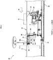
- FIG. 2 is a side view of the conveyor apparatus 10.
- the tray 14 is supported by a traveling unit 20.
- the traveling unit 20 travels along a rail (not shown in FIG. 2 ) laid along a conveying path.
- the entire traveling unit 20 is substantially shaped like a rectangular plate longitudinally extended along the conveying direction W.
- the traveling units 20 longitudinally arranged (adjacent to each other) along the conveying direction W are connected to each other via a coupler 22.
- the coupler 22 is not specifically illustrated.
- the bodies of the connected traveling units 20 can vertically and horizontally pivot about the coupler 22. Thus, even if the traveling units 20 travel along curves or ups and downs in the conveying path, the line of traveling units 20 can travel along the shape of the conveying path.
- the traveling unit 20 supports the tray 14 via an inclining part 24.
- the inclining part 24 rotates a tray support member 25, which vertically extends so as to support the tray 14, by a driving force of a motor 26 and the like around an inclination axis P parallel to the conveying direction W, thereby inclining the tray 14 so as to incline the article support surface 14a of the tray 14 from the horizontal plane.
- a plate support part 30 supporting the infill plate 16 is provided at the front of the traveling unit 20 with respect to the conveying direction W.
- the plate support part 30 includes a plate inclining shaft 32 (infilling member inclining shaft) supported by the traveling unit 20 and a plate support 34 connected to the plate inclining shaft 32.
- the plate inclining shaft 32 is a long member axially extended along the conveying direction W.
- the plate inclining shaft 32 is extended coaxially with the inclination axis P of the tray 14. Moreover, the plate inclining shaft 32 can rotate about the axial direction. If the infill plate 16 is inclined, the plate support 34 and the plate inclining shaft 32 both rotate along the axial direction of the plate inclining shaft 32 according to the inclination.
- the plate support 34 includes a vertical part 34a that is connected to the plate inclining shaft 32 and is vertically extended upward, and front extending parts 34b that extend forward from the vertical part 34a in the conveying direction W. Moreover, a swing bar 38 is supported on the upper end of the vertical part 34a and the rear ends of the front extending parts 34b so as to form a swinging shaft laterally extending with respect to the conveying direction W. Furthermore, springs 36 vertically extending upward are respectively supported on the front sides of the front extending parts 34b. The infill plate 16 is supported from below by the swing bar 38 and the springs 36.
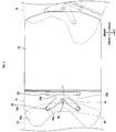
- the infill plate 16 can be made of, for example, injection-molded synthetic resin. As indicated by broken lines in the plan view of FIG. 3 , the infill plate 16 supported by the plate support part 30 is as large as the tray 14 in the width direction (a direction crossing the conveying direction W) and is longer than a clearance between the trays 14 in the longitudinal direction along the conveying direction W. The infill plate 16 is longer than the clearance in the longitudinal direction and thus extends from the front end of the rear tray 14 (the tray 14 indicated by a solid line on the right side in FIG. 3 ) to the bottom of the rear of the front tray 14 (the tray 14 indicated by a virtual line on the left side in FIG. 3 ), thereby completely filling the clearance in the longitudinal direction.
- a part of the infill plate 16 is disposed under the rear of the front tray 14 (a part overlapping the tray 14 in plan view) and the part will be called a plate contact part 16a (infilling contact part). Moreover, a part of the tray 14 overlaps the plate contact part 16a (the rear end extended along the conveying path or the conveying direction W) and the part will be called a tray contact part 14b (support contact part).
- the traveling directions of the tray 14 and the infill plate 16 intersect each other as indicated on the right end of FIG. 3 , so that the vertically overlapping area of the tray 14 and the infill plate 16 is small on one of the right and left sides (the right side in FIG. 3 ) and is large on the other side (the left side in FIG. 3 ) unlike when traveling on a linear part. Also in this case, in order to completely close the clearance, the right and left parts of the infill plate 16 in the width direction have larger longitudinal dimensions than the center of the infill plate 16 in the width direction.
- the bottom of the front side (plate contact part 16a) of the infill plate 16 is supported from below by the springs 36.
- a bar fitting part 38a e.g., a groove or a hole sized to be fit to the swing bar 38 is provided below the rear side of the infill plate 16 (in this configuration, the bar fitting part 38a is a hole).
- the swing bar 38 fit into the bar fitting part 38a is supported by the plate support part 30.
- the infill plate 16 can vertically swing around the axis of the swing bar 38.
- the plate contact part 16a located at the front of the infill plate 16 has a higher degree of upward curving (curvature) than the tray contact part 14b located at the rear of the tray 14.
- the top surface of the plate contact part 16a has a smaller curvature radius than the bottom of the tray contact part 14b.
- the plate contact part 16a in the width direction is entirely brought into contact with the tray contact part 14b by being urged with the springs 36.
- the front extending parts 34b of the plate support 34 are branches extending forward to the right and left.
- the two branch front extending parts 34b support the respective springs 36 on the front ends.
- the two springs 36 are respectively disposed at two points separated in the width direction under the plate contact part 16a and support the plate contact part 16a.
- the spring 36 acting as an urging member When the spring 36 acting as an urging member is extended or compressed (displaced) from a length in a state of equilibrium (an external force is not applied), the spring 36 generates a force for restoration to the state of equilibrium, that is, a restoring force by the elasticity of the spring 36.
- the spring 36 in the state of equilibrium is designed to be longer than a distance from a position where the plate support part 30 in FIGS. 2 , 4A supports the spring 36 (specifically, the top surface of the front extending part 34b of the plate support 34) to the bottom of the tray contact part 14b.
- the springs 36 are compressed from a state of equilibrium in a state in which the center of the plate contact part 16a in the width direction is separated from the tray contact part 14b and the upper ends of the springs 36 are in contact with the underside of the central part of the plate contact part 16a in the width direction.
- the plate contact part 16a is likely to extend upward to the tray contact part 14b.
- the springs 36 extending upward press upward the central part of the plate contact part 16a in the width direction while the upper ends of the springs 36 are in contact with the plate contact part 16a.
- the infill plate 16 is made of a flexible material (e.g., injection-molded synthetic resin)
- the plate contact part 16a of the infill plate 16 is pressed to the tray contact part 14b by the springs 36
- the plate contact part 16a is bent along the shape of the underside of the tray contact part 14b by the flexibility of the plate contact part 16a.
- the top surface of the plate contact part 16a is in contact with the underside of the tray contact part 14b, so that the plate contact part 16a and the tray contact part 14b are in contact with each other over the width direction.
- the plate contact part 16a of the infill plate 16 is in contact with the tray contact part 14b of the tray 14, allowing the infill plate 16 to follow the movement of the tray 14. For example, when the tray 14 laterally inclines, the infill plate 16 is inclined with the tray 14 while being kept in contact with the tray 14.
- the plate contact part 16a serving as the infilling contact part has a larger curvature than the tray contact part 14b serving as the support contact part (the infill plate 16 has a smaller curvature radius than the tray 14).
- the ends of the plate contact part 16a in the width direction come into contact with the underside of the tray contact part 14b, vertically leaving no clearance on the ends in the width direction.
- the tray contact part 14b is urged to the plate contact part 16a by the springs 36 and the tray contact part 14b is in contact with the plate contact part 16a while being bent along the shape of the plate contact part 16a.
- the plate contact part 16a is brought into close contact with the plate contact part 16a at the center of the plate contact part 16a in the width direction as well as on the ends of the plate contact part 16a in the width direction, vertically leaving no clearance over the width direction.
- the upward curvature of the plate contact part 16a is larger than that of the tray contact part 14b (the plate contact part 16a has a smaller curvature radius than the tray contact part 14b).
- the curving affects the shape of the plate contact part 16a so as to slightly reduce the upward curvature (increase the curvature radius), thereby bringing the curvature of the plate contact part 16a close to that of the tray contact part 14b.
- the infill plate 16 is made of a material, e.g., resin that is likely to be deformed over an extended period of use, a clearance is not left between the infill plate 16 and the tray 14 by some deformation, thereby keeping normal functions for a long time.
- the infill plate 16 may curve downward to the front in the traveling direction (to the front end along the conveying path) as well as to the right and left in the width direction.
- the curvature of the front side of the plate contact part 16a is preferably somewhat larger than that of the tray contact part 14b (For understanding, the curvature of the plate contact part 16a is larger than an actual curvature in the balloon of FIG. 2 ).
- the curvature of the plate contact part 16a is desirably larger than that of the tray contact part 14b when viewed not only in the traveling direction (line A-A of FIG. 2 ) as shown in FIG. 4A but also from the side (in a direction crossing the traveling direction) as indicated in the balloon of FIG. 2 .
- the infill plate 16 is made of injection-molded resin, the infill plate 16 can be formed with curvatures in the width direction and longitudinal direction (bent in various directions) because of quite a high degree of flexibility in shape.
- ribs 17 may be provided on the underside of the infill plate 16 so as to increase the strength of the infill plate 16. If the ribs 17 are additionally provided after the infill plate 16 is fabricated without the ribs 17, for example, the ribs 17 formed as separate plate members for the infill plate 16 are attached to the underside of the infill plate 16 by welding. When the ribs 17 are welded to the underside of the infill plate 16, the infill plate 16 is slightly warped downward by heat of welding, and the downward warping affects the plate contact part 16a so as to slightly reduce the upward curvature.
- the warping does not separate the plate contact part 16a from the tray contact part 14b but brings the shape of the plate contact part 16a close to the shape of the tray contact part 14b.
- the plate contact part 16a is slightly warped by welding the ribs 17, a clearance is not left between the plate contact part 16a and the tray contact part 14b.
- a clearance between the trays 14 is filled with the infill plate 16 and a clearance between the infill plate 16 and the tray 14 is prevented from being left even if both ends of the infill plate 16 in the width direction are curved downward as a result of using the infill plate 16 for an extended period or repeatedly inclining the tray 14 in the lateral direction.
- a clearance is not left between the infill plate 16 and the tray 14 by the warp of the infill plate 16, thereby increasing the strength of the infill plate 16 later.
- another method may be used as follows: a load to the infill plate 16 is first checked by a test run on the conveyor apparatus 10 with the infill plate 16 not provided with the ribs 17, and then the ribs 17 are welded later according to desired strength.
- the infill plate 16 is made of a flexible material, e.g., synthetic resin and the plate contact part 16a of the infill plate 16 is urged by the springs 36 as shown in FIG. 4B , so that the plate contact part 16a is bent along the shape of the tray contact part 14b.
- the plate contact part 16a may be made of a material such as wood that is not so flexible, so that the plate contact part 16a is not bent along the shape of the tray contact part 14b. In this case, the plate contact part 16a is not bent and thus as shown in FIG. 4A , the center of the plate contact part 16a in the width direction is separated from the tray contact part 14b.
- the article 12 is prevented from partially falling between the tray contact part 14b and the center of the plate contact part 16a in the width direction.
- a step is provided between the plate contact part 16a of the infill plate 16 and the other rear part of the infill plate 16 and the rear end of the tray 14 is brought into contact with the perpendicular face of the step, a clearance is not left between the rear end of the tray 14 and the infill plate 16.
- the article 12 does not partially fall into a clearance between the tray contact part 14b and the center of the plate contact part 16a in the width direction.
- the infill plate 16 is made of a flexible material, a step is not necessary between the plate contact part 16a and the other part and thus the top surface of the infill plate 16 may be entirely smoothed.
- the entire infill plate 16 is made of a flexible material (e.g., injection-molded synthetic resin). Only the plate contact part 16a of the infill plate 16 may be flexible. For example, if the infill plate 16 is made of synthetic resin, the plate contact part 16a may have a small thickness and the other part may have a large thickness, so that the plate contact part 16a is likely to be bent while the other part is not easily bent.
- a flexible material e.g., injection-molded synthetic resin
- the two springs 36 are provided in the width direction.
- Three or more springs may be provided according to the sizes and shapes of the tray 14 and the infill plate 16. If the tray 14 and the infill plate 16 are extremely large in size, a load may be unevenly applied to the overall infill plate 16 by the elastic force of the two springs 36. The load can be evenly applied to the overall infill plate 16 by increasing the number of springs 36. If the tray 14 and the infill plate 16 are small in size, a load applied to the overall infill plate 16 is not so uneven even in the case of the single spring 36. Thus, the number of components may be reduced by placing the single spring 36, for example, under the center of the plate contact part 16a of the infill plate 16 in the width direction.
- the springs 36 shown in FIG. 5 are used as urging members for urging the plate contact part 16a to the tray contact part 14b. Any member may be used as long as the plate contact part 16a is always pressed to the tray contact part 14b.
- the spring 36 may be replaced with a restoring force member, e.g., a rubber cylinder or an air cylinder.
- the restoring force member generates a restoring force for restoration to a state of equilibrium according to a displacement from a state where an external force is not applied (a state of equilibrium).
- the restoring force member may be disposed so as to apply a restoring force in a direction that presses the plate contact part 16a to the tray contact part 14b, so that the infill plate 16 moves according to a movement of the tray 14 and the plate contact part 16a bends along the shape of the tray contact part 14b.
- the springs 36 are disposed under the plate contact part 16a so as to urge the plate contact part 16a to the tray contact part 14b.
- the springs 36 may be replaced with the infill plate 16 (particularly the plate contact part 16a) made of an elastic material, e.g., rubber, so that the plate contact part 16a is urged to the tray contact part 14b by the elasticity of the plate contact part 16a and is brought into contact with the tray contact part 14b while being bent along the shape of the tray contact part 14b.
- the plate contact part 16a can be urged to the tray contact part 14b without the springs 36. This eliminates the need for preparing the springs 36 and reduces the number of kinds of components constituting the conveyor apparatus 10.
- the cost of component acquisition can be lowered and the number of spare parts to be kept for maintenance can be reduced.
- the springs 36 do not need to be disposed and thus the process of assembly of the conveyor apparatus 10 can be simplified. This can reduce the initial cost of constructing the conveyor apparatus 10 and the maintenance cost.
- the curvature of the plate contact part 16a is substantially constant in the width direction.
- a point near one end of the plate contact part 16a in the width direction is more likely to curve downward than a point near the center of the plate contact part 16a in the width direction.
Landscapes
- Engineering & Computer Science (AREA)
- Mechanical Engineering (AREA)
- Discharge Of Articles From Conveyors (AREA)
- Chain Conveyers (AREA)
- Pallets (AREA)
- Rollers For Roller Conveyors For Transfer (AREA)
- Branching, Merging, And Special Transfer Between Conveyors (AREA)
- Framework For Endless Conveyors (AREA)
- Basic Packing Technique (AREA)
- Packaging Frangible Articles (AREA)
- Intermediate Stations On Conveyors (AREA)
Abstract
Description
- The present invention relates to a conveyor apparatus for transporting articles, and particularly relates to a conveyor apparatus for transporting articles placed on article supports such as a tray.
- Conveyor apparatuses are used in some facilities where a plurality of articles need to be conveyed from an origin to destinations, for example, in the case of an airport where passenger's baggage is conveyed from an airport check-in area to an area for loading the baggage into an airplane that is scheduled to board passengers. Such a conveyor apparatus conveys articles on trays (article supports) traveling on a conveying path and inclines the trays at positions for the placed articles (inclines the trays laterally with respect to the conveying direction), so that the articles are discharged into chutes disposed along the conveying path and connected to the destinations.
- In such a conveyor apparatus, a clearance is left between the adjacent article supports, that is, between the trays, so that part (e.g., the shoulder strap of a bag) of baggage (article) may be dropped or caught in the clearance. In order to solve the problem, as described in Patent Literature 1, a cover member for covering a clearance (gap) may be prepared.
- A cover member described in Patent Literature 1 is directly connected to the bottom of an article support member (tray) via a pivot or a pin and thus the cover member is inclined with the article support member being inclined.
- Patent Literature 1:
WO00/02802 - In this configuration, the cover member described in Patent Literature 1 is directly connected to the article support member at the center of the cover member in the width direction (a direction crossing the conveying direction). Thus, the weight of the cover member is supported only at the center of the cover member in the width direction. In other words, the weight of one end of the cover member in the width direction is not supported and thus after an extended period of use in this state, one end of the cover member may curve downward because of the weight of the cover member. This leaves a vertical clearance between the end of the cover member in the width direction and the article support member, so that baggage may be partially dropped or caught in the clearance. Moreover, when the article support member inclines, one end of the cover member in the width direction is pressed from the article support member. This press also may curve downward one end of the cover member in the width direction.
- Patent Literature 1 also describes a method of supporting the cover member by means of a support element reinforced with a rib, as a supporting method of the cover member. However, this method also requires the support element in addition to the cover member, as a structure for filling a clearance between the article support members. This increases the number of components and the cost of constructing conveyor equipment. If a rib is additionally mounted on the cover member by welding in the absence of the support element, heat for welding may warp the cover member toward the mounting surface of the rib, that is, the underside of the cover member, causing a difference in shape between the cover member and the article support member. This leaves a clearance between the cover member and the article support member.
- An object of the present invention is to provide a conveyor apparatus that prevents a clearance from being vertically left between an article support and one end of an infilling member in the width direction while suppressing the cost of constructing conveyor equipment without the need for a support element, the infilling member filling a gap between the article supports arranged on a conveying path.
- In order to solve the problem, a conveyor apparatus according to an embodiment of the present invention is a conveyor apparatus for conveying articles, including: a plurality of traveling units that travel in series along a conveying path for the articles; and a plurality of article supports that have article support surfaces for supporting the articles and that are caused to travel on the conveying path by the respective traveling units, the conveyor apparatus further including infilling members provided for the respective article ' supports, the infilling member filling a clearance between the article supports longitudinally adjacent to each other in the conveying path, in which the article support has a support contact part on the rear end along the conveying path, the infilling member has an infilling contact part on the front end along the conveying path, the infilling contact part being in contact with the support contact part, and the infilling contact part has a larger curvature than the support contact part.
- With this configuration, a difference in curvature between the infilling contact part and the support contact part allows the infilling contact portion of the infilling member to securely come into contact with the support contact part of the article support, vertically leaving no clearance on one end of the infilling member in the width direction. Furthermore, even if one end of the infilling member in the width direction curves downward (the curvature decreases), the curvature of the infilling contact part is brought closer to that of the support contact part. Thus, the infilling contact part is more securely brought into contact with the support contact part, vertically leaving no clearance. Similarly, even if a rib is additionally attached to the infilling contact part of the infilling member by welding and thus the infilling contact part is slightly warped downward (the curvature decreases), the curvature of the infilling contact part is brought closer to that of the support contact part, vertically leaving no clearance.
- In addition to the configuration, the conveyor apparatus according to the embodiment the present invention may further include an urging member that urges the infilling contact part of the infilling member to the support contact part of the article support, in which the infilling contact part is made of a flexible material, and the infilling contact part may be urged to the support contact part by the urging member so as to come into contact with the support contact part while being bent along the shape of the support contact part.
- With this configuration, even if the infilling contact part and the support contact part have different shapes because of a difference in curvature between the infilling contact part and the support contact part, the urging member urges the infilling contact part to the support contact part so as to shape the infilling contact part along the support contact part, thereby completely filling a clearance between the infilling contact part and the support contact part.
- In addition to the configuration, the conveyor apparatus according to the embodiment of the present invention may be configured such that the infilling contact part of the infilling member is made of an elastic material and the infilling contact part may be brought into contact with the support contact part by the elasticity of the infilling contact part while being bent along the shape of the support contact part of the article support.
- With this configuration, even if the infilling contact part and the support contact part have different shapes because of a difference in curvature between the infilling contact part and the support contact part, the infilling contact part is shaped along the shape of the support contact part by the elasticity of the infilling contact part, thereby completely filling a clearance between the infilling contact part and the support contact part.
- In addition to the configuration, in the conveyor apparatus according to the embodiment of the present invention, the infilling member may be formed such that the curvature of the infilling contact part of the infilling member increases toward one end of the infilling member.
- With this configuration, the curvature of the infilling contact part increases toward the vicinity of one end of the infilling member that is likely to curve downward. Thus, even if a part around the center of the infilling contact part does not considerably curve downward while the vicinity of one end of the infilling contact part curves downward to a somewhat high degree, a clearance between the infilling contact part and the support contact part is kept closed. Moreover, for example, when the article support travels on a curve in the conveying path, one end of the infilling contact part may receive a larger load than a part around the center. Also in this case, a curvature on one end is larger than that of a part around the center, thereby keeping the infilling contact part and the support contact part in close contact with each other.
- According to the conveyor apparatus of the present invention, a clearance between the article supports is filled with the infilling member and a clearance is prevented from being left between the infilling member and the article support even if both ends of the infilling member in the width direction are curved downward by the weight of the infilling member after an extended period of use of the infilling member. This eliminates the need for changing the infilling members over an extended period. Thus, the number of spare infilling members can be reduced, thereby suppressing the cost of resource acquisition for operating the conveyor apparatus. Moreover, the need for a support element can be eliminated unlike in the related art, thereby inexpensively constructing the conveyor apparatus.
-
-
FIG. 1 is a perspective view showing a part of a conveyor apparatus as an example of an embodiment of the present invention. -
FIG. 2 is a side view showing the conveyor apparatus according to the embodiment. -
FIG. 3 is a plan view showing a plate support part for the conveyor apparatus according to the embodiment. -
FIG. 4A is a cross-sectional view showing a state immediately before an infill plate is urged by springs, taken along line A-A ofFIG. 2 . -
FIG. 4B is a cross-sectional view showing a state after the infill plate is urged by the springs, taken along line A-A ofFIG. 2 . -
FIG. 5 is a perspective bottom view showing a state around a traveling unit for the conveyor apparatus according to the embodiment. -
FIG. 1 shows a part of aconveyor apparatus 10 as an example of an embodiment of the present invention. In theconveyor apparatus 10, anarticle 12 to be conveyed is placed on atray 14 serving as an article support and is conveyed in a conveying direction W. In this configuration, a direction along the conveying direction W is referred to as a longitudinal direction and a direction crossing the conveying direction W is referred to as a lateral direction or a width direction. The longitudinal and lateral directions are determined as indicated by arrows inFIG. 1 . As shown inFIG. 1 , thetrays 14 are arranged in series along the conveying direction W. Each of thetrays 14 can support thearticle 12 on anarticle support surface 14a. As shown inFIG. 4A , the top surface of thetray 14 is curved slightly upward. Thus, when thearticle 12 is placed on the top surface of thetray 14, thearticle 12 is moved by the weight of thearticle 12 to the center of thetray 14 in the width direction along the curve of the top surface of thetray 14. This prevents thearticle 12 from laterally falling in the width direction of thetray 14, thereby stably supporting thearticle 12 at the center of thetray 14 in the width direction. - As indicated by a virtual line in
FIG. 1 , thetray 14 can be laterally inclined with respect to the conveying direction W (FIG. 1 only shows atray 14 inclined to the left). Thus, thearticle support surface 14a of thetray 14 can be inclined from a horizontal plane so as to discharge thearticle 12 into one of a plurality ofchutes 18 placed along the conveying direction W. Thechutes 18 are connected to the respective destinations. The operation of theconveyor apparatus 10 is controlled so as to discharge thearticle 12 on thetray 14 into thechute 18 connected to the destination of thearticle 12. - Moreover, an
infill plate 16 serving as an infilling member is provided for each of thetrays 14 so as to fill a clearance between the twotrays 14 longitudinally arranged (adjacent to each other) along the conveying direction W. This configuration prevents a part or the whole of thearticle 12 from falling into a clearance between thetrays 14. Theinfill plate 16 is inclined with the correspondingtray 14 when thetray 14 is inclined. -
FIG. 2 is a side view of theconveyor apparatus 10. As shown inFIG. 2 , thetray 14 is supported by a travelingunit 20. The travelingunit 20 travels along a rail (not shown inFIG. 2 ) laid along a conveying path. Theentire traveling unit 20 is substantially shaped like a rectangular plate longitudinally extended along the conveying direction W. The travelingunits 20 longitudinally arranged (adjacent to each other) along the conveying direction W are connected to each other via acoupler 22. Thecoupler 22 is not specifically illustrated. The bodies of the connected travelingunits 20 can vertically and horizontally pivot about thecoupler 22. Thus, even if the travelingunits 20 travel along curves or ups and downs in the conveying path, the line of travelingunits 20 can travel along the shape of the conveying path. - Moreover, the traveling
unit 20 supports thetray 14 via an incliningpart 24. The incliningpart 24 rotates atray support member 25, which vertically extends so as to support thetray 14, by a driving force of a motor 26 and the like around an inclination axis P parallel to the conveying direction W, thereby inclining thetray 14 so as to incline thearticle support surface 14a of thetray 14 from the horizontal plane. - Furthermore, a
plate support part 30 supporting theinfill plate 16 is provided at the front of the travelingunit 20 with respect to the conveying direction W. Theplate support part 30 includes a plate inclining shaft 32 (infilling member inclining shaft) supported by the travelingunit 20 and aplate support 34 connected to theplate inclining shaft 32. - The
plate inclining shaft 32 is a long member axially extended along the conveying direction W. Theplate inclining shaft 32 is extended coaxially with the inclination axis P of thetray 14. Moreover, theplate inclining shaft 32 can rotate about the axial direction. If theinfill plate 16 is inclined, theplate support 34 and theplate inclining shaft 32 both rotate along the axial direction of theplate inclining shaft 32 according to the inclination. - The
plate support 34 includes avertical part 34a that is connected to theplate inclining shaft 32 and is vertically extended upward, andfront extending parts 34b that extend forward from thevertical part 34a in the conveying direction W. Moreover, aswing bar 38 is supported on the upper end of thevertical part 34a and the rear ends of the front extendingparts 34b so as to form a swinging shaft laterally extending with respect to the conveying direction W. Furthermore, springs 36 vertically extending upward are respectively supported on the front sides of the front extendingparts 34b. Theinfill plate 16 is supported from below by theswing bar 38 and thesprings 36. - The
infill plate 16 can be made of, for example, injection-molded synthetic resin. As indicated by broken lines in the plan view ofFIG. 3 , theinfill plate 16 supported by theplate support part 30 is as large as thetray 14 in the width direction (a direction crossing the conveying direction W) and is longer than a clearance between thetrays 14 in the longitudinal direction along the conveying direction W. Theinfill plate 16 is longer than the clearance in the longitudinal direction and thus extends from the front end of the rear tray 14 (thetray 14 indicated by a solid line on the right side inFIG. 3 ) to the bottom of the rear of the front tray 14 (thetray 14 indicated by a virtual line on the left side inFIG. 3 ), thereby completely filling the clearance in the longitudinal direction. As will be discussed below, a part of theinfill plate 16 is disposed under the rear of the front tray 14 (a part overlapping thetray 14 in plan view) and the part will be called aplate contact part 16a (infilling contact part). Moreover, a part of thetray 14 overlaps theplate contact part 16a (the rear end extended along the conveying path or the conveying direction W) and the part will be called atray contact part 14b (support contact part). - When the
trays 14 travel on a curve, the traveling directions of thetray 14 and theinfill plate 16 intersect each other as indicated on the right end ofFIG. 3 , so that the vertically overlapping area of thetray 14 and theinfill plate 16 is small on one of the right and left sides (the right side inFIG. 3 ) and is large on the other side (the left side inFIG. 3 ) unlike when traveling on a linear part. Also in this case, in order to completely close the clearance, the right and left parts of theinfill plate 16 in the width direction have larger longitudinal dimensions than the center of theinfill plate 16 in the width direction. - As shown in a perspective view in
FIG. 5 , the bottom of the front side (plate contact part 16a) of theinfill plate 16 is supported from below by thesprings 36. Moreover, a barfitting part 38a, e.g., a groove or a hole sized to be fit to theswing bar 38 is provided below the rear side of the infill plate 16 (in this configuration, thebar fitting part 38a is a hole). As has been discussed, theswing bar 38 fit into thebar fitting part 38a is supported by theplate support part 30. Theinfill plate 16 can vertically swing around the axis of theswing bar 38. - As shown in
FIG. 4A , when theinfill plate 16 is viewed in a direction along line A-A ofFIG. 2 (the front side along the conveying direction W), theplate contact part 16a located at the front of theinfill plate 16 has a higher degree of upward curving (curvature) than thetray contact part 14b located at the rear of thetray 14. In other words, the top surface of theplate contact part 16a has a smaller curvature radius than the bottom of thetray contact part 14b. Thus, in the absence of urging by thesprings 36, the ends (right and left ends) of the top surface of theplate contact part 16a in the width direction are in contact with the underside of thetray contact part 14b as shown inFIG. 4A ; whereas the center of theplate contact part 16a in the width direction is not in contact with thetray contact part 14b. As will be discussed later, as shown inFIG. 4B , theplate contact part 16a in the width direction is entirely brought into contact with thetray contact part 14b by being urged with thesprings 36. - As shown in
FIGS. 3 and5 , thefront extending parts 34b of theplate support 34 are branches extending forward to the right and left. The two branchfront extending parts 34b support therespective springs 36 on the front ends. Thus, the twosprings 36 are respectively disposed at two points separated in the width direction under theplate contact part 16a and support theplate contact part 16a. - When the
spring 36 acting as an urging member is extended or compressed (displaced) from a length in a state of equilibrium (an external force is not applied), thespring 36 generates a force for restoration to the state of equilibrium, that is, a restoring force by the elasticity of thespring 36. Thespring 36 in the state of equilibrium is designed to be longer than a distance from a position where theplate support part 30 inFIGS. 2 ,4A supports the spring 36 (specifically, the top surface of the front extendingpart 34b of the plate support 34) to the bottom of thetray contact part 14b. Thus, as shown inFIG. 4A , thesprings 36 are compressed from a state of equilibrium in a state in which the center of theplate contact part 16a in the width direction is separated from thetray contact part 14b and the upper ends of thesprings 36 are in contact with the underside of the central part of theplate contact part 16a in the width direction. Thus, theplate contact part 16a is likely to extend upward to thetray contact part 14b. Thesprings 36 extending upward press upward the central part of theplate contact part 16a in the width direction while the upper ends of thesprings 36 are in contact with theplate contact part 16a. At this point, if theinfill plate 16 is made of a flexible material (e.g., injection-molded synthetic resin), when theplate contact part 16a of theinfill plate 16 is pressed to thetray contact part 14b by thesprings 36, theplate contact part 16a is bent along the shape of the underside of thetray contact part 14b by the flexibility of theplate contact part 16a. Finally, as shown inFIG. 4B , the top surface of theplate contact part 16a is in contact with the underside of thetray contact part 14b, so that theplate contact part 16a and thetray contact part 14b are in contact with each other over the width direction. - As has been discussed, the
plate contact part 16a of theinfill plate 16 is in contact with thetray contact part 14b of thetray 14, allowing theinfill plate 16 to follow the movement of thetray 14. For example, when thetray 14 laterally inclines, theinfill plate 16 is inclined with thetray 14 while being kept in contact with thetray 14. - In the
conveyor apparatus 10 of the present embodiment, theplate contact part 16a serving as the infilling contact part has a larger curvature than thetray contact part 14b serving as the support contact part (theinfill plate 16 has a smaller curvature radius than the tray 14). Thus, the ends of theplate contact part 16a in the width direction come into contact with the underside of thetray contact part 14b, vertically leaving no clearance on the ends in the width direction. - Moreover, the
tray contact part 14b is urged to theplate contact part 16a by thesprings 36 and thetray contact part 14b is in contact with theplate contact part 16a while being bent along the shape of theplate contact part 16a. Thus, theplate contact part 16a is brought into close contact with theplate contact part 16a at the center of theplate contact part 16a in the width direction as well as on the ends of theplate contact part 16a in the width direction, vertically leaving no clearance over the width direction. - Furthermore, before the contact part is bent by urging, the upward curvature of the
plate contact part 16a is larger than that of thetray contact part 14b (theplate contact part 16a has a smaller curvature radius than thetray contact part 14b). Thus, even if the ends of theinfill plate 16 in the width direction are slightly curved downward by the weight of theinfill plate 16 as a result of using theinfill plate 16 over an extended period, the curving affects the shape of theplate contact part 16a so as to slightly reduce the upward curvature (increase the curvature radius), thereby bringing the curvature of theplate contact part 16a close to that of thetray contact part 14b. In other words, even if the ends in the width direction are curved downward, the curving does not separate theplate contact part 16a from thetray contact part 14b but brings the shape of theplate contact part 16a close to that of thetray contact part 14b. Thus, even if the ends of theplate contact part 16a in the width direction are slightly curved downward, a clearance is not left between theplate contact part 16a and thetray contact part 14b. Similarly, even if the ends of theplate contact part 16a in the width direction are slightly curved downward as a result of laterally inclining thetray 14 many times so as to press down the ends of theplate contact part 16a in the lateral direction (width direction) many times, a clearance is not left between theplate contact part 16a and thetray contact part 14b. Thus, even if theinfill plate 16 is made of a material, e.g., resin that is likely to be deformed over an extended period of use, a clearance is not left between theinfill plate 16 and thetray 14 by some deformation, thereby keeping normal functions for a long time. - The
infill plate 16 may curve downward to the front in the traveling direction (to the front end along the conveying path) as well as to the right and left in the width direction. In order to prevent a clearance from being vertically left between thetray 14 and theinfill plate 16 even if theinfill plate 16 curves downward to the front, as schematically illustrated in the balloon ofFIG. 2 , the curvature of the front side of theplate contact part 16a is preferably somewhat larger than that of thetray contact part 14b (For understanding, the curvature of theplate contact part 16a is larger than an actual curvature in the balloon ofFIG. 2 ). In other words, the curvature of theplate contact part 16a is desirably larger than that of thetray contact part 14b when viewed not only in the traveling direction (line A-A ofFIG. 2 ) as shown inFIG. 4A but also from the side (in a direction crossing the traveling direction) as indicated in the balloon ofFIG. 2 . If theinfill plate 16 is made of injection-molded resin, theinfill plate 16 can be formed with curvatures in the width direction and longitudinal direction (bent in various directions) because of quite a high degree of flexibility in shape. - As shown in
FIGS. 4A, 4B , and5 ,ribs 17 may be provided on the underside of theinfill plate 16 so as to increase the strength of theinfill plate 16. If theribs 17 are additionally provided after theinfill plate 16 is fabricated without theribs 17, for example, theribs 17 formed as separate plate members for theinfill plate 16 are attached to the underside of theinfill plate 16 by welding. When theribs 17 are welded to the underside of theinfill plate 16, theinfill plate 16 is slightly warped downward by heat of welding, and the downward warping affects theplate contact part 16a so as to slightly reduce the upward curvature. Thus, the warping does not separate theplate contact part 16a from thetray contact part 14b but brings the shape of theplate contact part 16a close to the shape of thetray contact part 14b. Thus, even if theplate contact part 16a is slightly warped by welding theribs 17, a clearance is not left between theplate contact part 16a and thetray contact part 14b. - As has been discussed, according to the
conveyor apparatus 10 of the present embodiment, a clearance between thetrays 14 is filled with theinfill plate 16 and a clearance between theinfill plate 16 and thetray 14 is prevented from being left even if both ends of theinfill plate 16 in the width direction are curved downward as a result of using theinfill plate 16 for an extended period or repeatedly inclining thetray 14 in the lateral direction. This eliminates the need for exchanging theinfill plate 16 each time theinfill plate 16 is deformed, thereby suppressing the cost of resource acquisition for operating theconveyor apparatus 10. Moreover, even if theribs 17 are welded to theinfill plate 16 later, a clearance is not left between theinfill plate 16 and thetray 14 by the warp of theinfill plate 16, thereby increasing the strength of theinfill plate 16 later. For example, another method may be used as follows: a load to theinfill plate 16 is first checked by a test run on theconveyor apparatus 10 with theinfill plate 16 not provided with theribs 17, and then theribs 17 are welded later according to desired strength. - In the present embodiment, the
infill plate 16 is made of a flexible material, e.g., synthetic resin and theplate contact part 16a of theinfill plate 16 is urged by thesprings 36 as shown inFIG. 4B , so that theplate contact part 16a is bent along the shape of thetray contact part 14b. Theplate contact part 16a may be made of a material such as wood that is not so flexible, so that theplate contact part 16a is not bent along the shape of thetray contact part 14b. In this case, theplate contact part 16a is not bent and thus as shown inFIG. 4A , the center of theplate contact part 16a in the width direction is separated from thetray contact part 14b. If theplate contact part 16a of theinfill plate 16 has a different shape from the other part (rear part) of theinfill plate 16, thearticle 12 is prevented from partially falling between thetray contact part 14b and the center of theplate contact part 16a in the width direction. For example, if a step is provided between theplate contact part 16a of theinfill plate 16 and the other rear part of theinfill plate 16 and the rear end of thetray 14 is brought into contact with the perpendicular face of the step, a clearance is not left between the rear end of thetray 14 and theinfill plate 16. Thus, thearticle 12 does not partially fall into a clearance between thetray contact part 14b and the center of theplate contact part 16a in the width direction. Needless to say, if theinfill plate 16 is made of a flexible material, a step is not necessary between theplate contact part 16a and the other part and thus the top surface of theinfill plate 16 may be entirely smoothed. - In the present embodiment, it is assumed that the
entire infill plate 16 is made of a flexible material (e.g., injection-molded synthetic resin). Only theplate contact part 16a of theinfill plate 16 may be flexible. For example, if theinfill plate 16 is made of synthetic resin, theplate contact part 16a may have a small thickness and the other part may have a large thickness, so that theplate contact part 16a is likely to be bent while the other part is not easily bent. - In the present embodiment, as shown in
FIG. 3 , the twosprings 36 are provided in the width direction. Three or more springs may be provided according to the sizes and shapes of thetray 14 and theinfill plate 16. If thetray 14 and theinfill plate 16 are extremely large in size, a load may be unevenly applied to theoverall infill plate 16 by the elastic force of the two springs 36. The load can be evenly applied to theoverall infill plate 16 by increasing the number ofsprings 36. If thetray 14 and theinfill plate 16 are small in size, a load applied to theoverall infill plate 16 is not so uneven even in the case of thesingle spring 36. Thus, the number of components may be reduced by placing thesingle spring 36, for example, under the center of theplate contact part 16a of theinfill plate 16 in the width direction. - Furthermore, in the present embodiment, the
springs 36 shown inFIG. 5 are used as urging members for urging theplate contact part 16a to thetray contact part 14b. Any member may be used as long as theplate contact part 16a is always pressed to thetray contact part 14b. For example, thespring 36 may be replaced with a restoring force member, e.g., a rubber cylinder or an air cylinder. The restoring force member generates a restoring force for restoration to a state of equilibrium according to a displacement from a state where an external force is not applied (a state of equilibrium). Even if a restoring force member other than thesprings 36 is used, the restoring force member may be disposed so as to apply a restoring force in a direction that presses theplate contact part 16a to thetray contact part 14b, so that theinfill plate 16 moves according to a movement of thetray 14 and theplate contact part 16a bends along the shape of thetray contact part 14b. - In the present embodiment, as shown in
FIG. 5 , thesprings 36 are disposed under theplate contact part 16a so as to urge theplate contact part 16a to thetray contact part 14b. Thesprings 36 may be replaced with the infill plate 16 (particularly theplate contact part 16a) made of an elastic material, e.g., rubber, so that theplate contact part 16a is urged to thetray contact part 14b by the elasticity of theplate contact part 16a and is brought into contact with thetray contact part 14b while being bent along the shape of thetray contact part 14b. With this configuration, theplate contact part 16a can be urged to thetray contact part 14b without thesprings 36. This eliminates the need for preparing thesprings 36 and reduces the number of kinds of components constituting theconveyor apparatus 10. Thus, the cost of component acquisition can be lowered and the number of spare parts to be kept for maintenance can be reduced. Moreover, thesprings 36 do not need to be disposed and thus the process of assembly of theconveyor apparatus 10 can be simplified. This can reduce the initial cost of constructing theconveyor apparatus 10 and the maintenance cost. - In the present embodiment, as shown in
FIG. 4A , the curvature of theplate contact part 16a is substantially constant in the width direction. Actually, a point near one end of theplate contact part 16a in the width direction is more likely to curve downward than a point near the center of theplate contact part 16a in the width direction. Thus, it is desirable to form theinfill plate 16 so as to gradually and continuously increase the curvature toward the ends of theplate contact part 16a (gradually reduce the curvature radius). Furthermore, it is desirable to form theinfill plate 16 so as to gradually and continuously increase the curvature toward the front end along the conveying path as well as in the width direction. -
- 10
- conveyor apparatus
- 14
- tray
- 16
- infill plate
- 20
- traveling unit
- 22
- coupler
- 24
- inclining part
- 36
- spring
- 38
- swing bar
Claims (4)
- A conveyor apparatus for conveying articles, comprising: a plurality of traveling units that travel in series along a conveying path for the articles; and a plurality of article supports that have article support surfaces for supporting the articles and that are caused to travel on the conveying path by the respective traveling units,
the conveyor apparatus further comprising infilling members provided for the respective article supports, the infilling member filling a clearance between the article supports longitudinally adjacent to each other in the conveying path,
the article support including a support contact part on a rear end of the article support along the conveying path,
the infilling member including an infilling contact part on a front end of the infilling member along the conveying path, the infilling contact part being in contact with the support contact part, and
the infilling contact part having a larger curvature than the support contact part. - The conveyor apparatus according to claim 1, comprising an urging member that urges the infilling contact part of the infilling member to the support contact part of the article support,
wherein the infilling contact part is made of a flexible material, and
the infilling contact part is urged to the support contact part by the urging member so as to come into contact with the support contact part while being bent along a shape of the support contact part. - The conveyor apparatus according to one of claims 1 and 2, wherein the infilling contact part of the infilling member is made of an elastic material, and the infilling contact part is in contact with the support contact part while being bent along the shape of the support contact part of the article support by elasticity of the infilling contact part.
- The conveyor apparatus according to any one of claims 1 to 3, wherein the infilling member is formed such that the curvature of the infilling contact part of the infilling member increases toward one end of the infilling member.
Applications Claiming Priority (2)
| Application Number | Priority Date | Filing Date | Title |
|---|---|---|---|
| JP2016029438A JP6451660B2 (en) | 2016-02-19 | 2016-02-19 | Conveyor equipment |
| PCT/JP2017/005096 WO2017141864A1 (en) | 2016-02-19 | 2017-02-13 | Conveyor device |
Publications (3)
| Publication Number | Publication Date |
|---|---|
| EP3418224A1 true EP3418224A1 (en) | 2018-12-26 |
| EP3418224A4 EP3418224A4 (en) | 2019-10-09 |
| EP3418224B1 EP3418224B1 (en) | 2025-06-11 |
Family
ID=59625972
Family Applications (1)
| Application Number | Title | Priority Date | Filing Date |
|---|---|---|---|
| EP17753121.7A Active EP3418224B1 (en) | 2016-02-19 | 2017-02-13 | Conveyor apparatus |
Country Status (14)
| Country | Link |
|---|---|
| US (1) | US10294033B2 (en) |
| EP (1) | EP3418224B1 (en) |
| JP (1) | JP6451660B2 (en) |
| CN (1) | CN108698763B (en) |
| AU (1) | AU2017221545B2 (en) |
| CA (1) | CA3014405C (en) |
| DK (1) | DK3418224T3 (en) |
| ES (1) | ES3039127T3 (en) |
| FI (1) | FI3418224T3 (en) |
| NZ (1) | NZ744943A (en) |
| RU (1) | RU2732663C2 (en) |
| SG (1) | SG11201806749TA (en) |
| TW (2) | TWI724101B (en) |
| WO (1) | WO2017141864A1 (en) |
Families Citing this family (4)
| Publication number | Priority date | Publication date | Assignee | Title |
|---|---|---|---|---|
| JP6508086B2 (en) * | 2016-02-19 | 2019-05-08 | 株式会社ダイフク | Conveyor equipment |
| CN107673045A (en) * | 2017-09-15 | 2018-02-09 | 杨春花 | A kind of modified turning device |
| JP6889411B2 (en) * | 2018-04-27 | 2021-06-18 | 株式会社ダイフク | Transport sorting device |
| JP7189420B2 (en) * | 2018-08-09 | 2022-12-14 | シブヤ精機株式会社 | Goods sorting device |
Family Cites Families (13)
| Publication number | Priority date | Publication date | Assignee | Title |
|---|---|---|---|---|
| US3231066A (en) * | 1964-05-06 | 1966-01-25 | Prospect Mfg Co Inc | Tilting conveyor apparatus |
| CH688719A5 (en) * | 1994-11-16 | 1998-01-30 | Grapha Holding Ag Patentwesen | Distribution elevator for cargo. |
| NL9500161A (en) * | 1995-01-30 | 1996-09-02 | Vanderlande Ind Nederland | Transport device. |
| US6050390A (en) * | 1996-04-15 | 2000-04-18 | Mantissa Corporation | Chute for a tilt tray sorter |
| DE19718269A1 (en) * | 1997-04-30 | 1998-11-05 | Beumer Maschf Bernhard | Sliding sorting conveyor for one-piece items |
| EP1042192B1 (en) * | 1997-12-23 | 2003-05-14 | Crisplant A/S | An articulated conveyor |
| US6607066B1 (en) * | 1998-07-10 | 2003-08-19 | Crisplant A/S | Conveyor |
| DE19914386C2 (en) * | 1999-03-30 | 2001-03-15 | Beumer Maschf Gmbh & Co Kg | General cargo (continuous) conveyor |
| JP3994711B2 (en) * | 2001-10-01 | 2007-10-24 | 株式会社ダイフク | Transport device |
| NL1022682C2 (en) * | 2003-02-14 | 2004-08-17 | Vanderlande Ind Nederland | Device and method for sorting products. |
| NL1026137C2 (en) * | 2004-05-07 | 2005-11-08 | Vanderlande Ind Nederland | Device for sorting products. |
| CN103143510B (en) * | 2013-04-10 | 2014-07-30 | 民航成都物流技术有限公司 | Tilting pan type high-speed automatic baggage sorting machine |
| US9902569B2 (en) * | 2014-05-22 | 2018-02-27 | Beumer Group A/S | Sorting system having cover plates closing gaps between support structures |
-
2016
- 2016-02-19 JP JP2016029438A patent/JP6451660B2/en active Active
-
2017
- 2017-02-09 TW TW106104221A patent/TWI724101B/en active
- 2017-02-09 TW TW109143640A patent/TW202122325A/en unknown
- 2017-02-13 US US16/077,629 patent/US10294033B2/en active Active
- 2017-02-13 CA CA3014405A patent/CA3014405C/en active Active
- 2017-02-13 DK DK17753121.7T patent/DK3418224T3/en active
- 2017-02-13 EP EP17753121.7A patent/EP3418224B1/en active Active
- 2017-02-13 SG SG11201806749TA patent/SG11201806749TA/en unknown
- 2017-02-13 ES ES17753121T patent/ES3039127T3/en active Active
- 2017-02-13 WO PCT/JP2017/005096 patent/WO2017141864A1/en not_active Ceased
- 2017-02-13 AU AU2017221545A patent/AU2017221545B2/en active Active
- 2017-02-13 CN CN201780011267.2A patent/CN108698763B/en active Active
- 2017-02-13 NZ NZ744943A patent/NZ744943A/en unknown
- 2017-02-13 FI FIEP17753121.7T patent/FI3418224T3/en active
- 2017-02-13 RU RU2018133031A patent/RU2732663C2/en active
Also Published As
| Publication number | Publication date |
|---|---|
| TW201730071A (en) | 2017-09-01 |
| US10294033B2 (en) | 2019-05-21 |
| RU2018133031A (en) | 2020-03-19 |
| JP6451660B2 (en) | 2019-01-16 |
| TW202122325A (en) | 2021-06-16 |
| EP3418224B1 (en) | 2025-06-11 |
| JP2017145123A (en) | 2017-08-24 |
| CA3014405A1 (en) | 2017-08-24 |
| RU2732663C2 (en) | 2020-09-21 |
| CN108698763A (en) | 2018-10-23 |
| RU2018133031A3 (en) | 2020-04-10 |
| FI3418224T3 (en) | 2025-08-22 |
| AU2017221545A1 (en) | 2018-08-23 |
| CN108698763B (en) | 2020-11-20 |
| ES3039127T3 (en) | 2025-10-17 |
| CA3014405C (en) | 2023-11-28 |
| EP3418224A4 (en) | 2019-10-09 |
| DK3418224T3 (en) | 2025-09-01 |
| NZ744943A (en) | 2021-12-24 |
| US20190055089A1 (en) | 2019-02-21 |
| TWI724101B (en) | 2021-04-11 |
| WO2017141864A1 (en) | 2017-08-24 |
| SG11201806749TA (en) | 2018-09-27 |
| AU2017221545B2 (en) | 2022-07-07 |
Similar Documents
| Publication | Publication Date | Title |
|---|---|---|
| AU2022203812B2 (en) | Conveyor apparatus | |
| EP3418224B1 (en) | Conveyor apparatus | |
| EP2655221B1 (en) | System and method for buffering pieces of luggage | |
| CN104981419B (en) | Item carrier for sorting equipment | |
| EP3053858B1 (en) | Elastomeric force mitigating joint | |
| CN105035713A (en) | Selecting plate installing apparatus for selecting plate transmitter | |
| US20210333143A1 (en) | A Weighing System | |
| US3223215A (en) | Gravity conveyors | |
| US10597047B2 (en) | Method and transport vehicle for loading and unloading | |
| JP2024519781A (en) | Product Transport System and Product Support System | |
| KR101016322B1 (en) | Conveying belt guide device | |
| JP2652496B2 (en) | Method and apparatus for discharging articles from conveyor device | |
| JP5733529B2 (en) | Conveyor and sorting equipment |
Legal Events
| Date | Code | Title | Description |
|---|---|---|---|
| STAA | Information on the status of an ep patent application or granted ep patent |
Free format text: STATUS: THE INTERNATIONAL PUBLICATION HAS BEEN MADE |
|
| PUAI | Public reference made under article 153(3) epc to a published international application that has entered the european phase |
Free format text: ORIGINAL CODE: 0009012 |
|
| STAA | Information on the status of an ep patent application or granted ep patent |
Free format text: STATUS: REQUEST FOR EXAMINATION WAS MADE |
|
| 17P | Request for examination filed |
Effective date: 20180919 |
|
| AK | Designated contracting states |
Kind code of ref document: A1 Designated state(s): AL AT BE BG CH CY CZ DE DK EE ES FI FR GB GR HR HU IE IS IT LI LT LU LV MC MK MT NL NO PL PT RO RS SE SI SK SM TR |
|
| AX | Request for extension of the european patent |
Extension state: BA ME |
|
| DAV | Request for validation of the european patent (deleted) | ||
| DAX | Request for extension of the european patent (deleted) | ||
| A4 | Supplementary search report drawn up and despatched |
Effective date: 20190909 |
|
| RIC1 | Information provided on ipc code assigned before grant |
Ipc: B65G 17/06 20060101ALI20190903BHEP Ipc: B65G 17/32 20060101AFI20190903BHEP Ipc: B65G 47/38 20060101ALI20190903BHEP Ipc: B65G 47/96 20060101ALI20190903BHEP |
|
| STAA | Information on the status of an ep patent application or granted ep patent |
Free format text: STATUS: EXAMINATION IS IN PROGRESS |
|
| 17Q | First examination report despatched |
Effective date: 20220530 |
|
| GRAP | Despatch of communication of intention to grant a patent |
Free format text: ORIGINAL CODE: EPIDOSNIGR1 |
|
| STAA | Information on the status of an ep patent application or granted ep patent |
Free format text: STATUS: GRANT OF PATENT IS INTENDED |
|
| INTG | Intention to grant announced |
Effective date: 20250123 |
|
| RIN1 | Information on inventor provided before grant (corrected) |
Inventor name: FUJIO, YOSHIHIKO |
|
| GRAS | Grant fee paid |
Free format text: ORIGINAL CODE: EPIDOSNIGR3 |
|
| GRAA | (expected) grant |
Free format text: ORIGINAL CODE: 0009210 |
|
| STAA | Information on the status of an ep patent application or granted ep patent |
Free format text: STATUS: THE PATENT HAS BEEN GRANTED |
|
| P01 | Opt-out of the competence of the unified patent court (upc) registered |
Free format text: CASE NUMBER: APP_18017/2025 Effective date: 20250414 |
|
| AK | Designated contracting states |
Kind code of ref document: B1 Designated state(s): AL AT BE BG CH CY CZ DE DK EE ES FI FR GB GR HR HU IE IS IT LI LT LU LV MC MK MT NL NO PL PT RO RS SE SI SK SM TR |
|
| REG | Reference to a national code |
Ref country code: GB Ref legal event code: FG4D |
|
| REG | Reference to a national code |
Ref country code: CH Ref legal event code: EP |
|
| REG | Reference to a national code |
Ref country code: DE Ref legal event code: R096 Ref document number: 602017089892 Country of ref document: DE |
|
| REG | Reference to a national code |
Ref country code: IE Ref legal event code: FG4D |
|
| REG | Reference to a national code |
Ref country code: NL Ref legal event code: FP |
|
| REG | Reference to a national code |
Ref country code: FI Ref legal event code: FGE |
|
| REG | Reference to a national code |
Ref country code: DK Ref legal event code: T3 Effective date: 20250828 |
|
| REG | Reference to a national code |
Ref country code: LT Ref legal event code: MG9D |
|
| PG25 | Lapsed in a contracting state [announced via postgrant information from national office to epo] |
Ref country code: GR Free format text: LAPSE BECAUSE OF FAILURE TO SUBMIT A TRANSLATION OF THE DESCRIPTION OR TO PAY THE FEE WITHIN THE PRESCRIBED TIME-LIMIT Effective date: 20250912 Ref country code: NO Free format text: LAPSE BECAUSE OF FAILURE TO SUBMIT A TRANSLATION OF THE DESCRIPTION OR TO PAY THE FEE WITHIN THE PRESCRIBED TIME-LIMIT Effective date: 20250911 |
|
| PG25 | Lapsed in a contracting state [announced via postgrant information from national office to epo] |
Ref country code: BG Free format text: LAPSE BECAUSE OF FAILURE TO SUBMIT A TRANSLATION OF THE DESCRIPTION OR TO PAY THE FEE WITHIN THE PRESCRIBED TIME-LIMIT Effective date: 20250611 |
|
| PG25 | Lapsed in a contracting state [announced via postgrant information from national office to epo] |
Ref country code: HR Free format text: LAPSE BECAUSE OF FAILURE TO SUBMIT A TRANSLATION OF THE DESCRIPTION OR TO PAY THE FEE WITHIN THE PRESCRIBED TIME-LIMIT Effective date: 20250611 |
|
| REG | Reference to a national code |
Ref country code: ES Ref legal event code: FG2A Ref document number: 3039127 Country of ref document: ES Kind code of ref document: T3 Effective date: 20251017 |
|
| PG25 | Lapsed in a contracting state [announced via postgrant information from national office to epo] |
Ref country code: RS Free format text: LAPSE BECAUSE OF FAILURE TO SUBMIT A TRANSLATION OF THE DESCRIPTION OR TO PAY THE FEE WITHIN THE PRESCRIBED TIME-LIMIT Effective date: 20250911 |
|
| PG25 | Lapsed in a contracting state [announced via postgrant information from national office to epo] |
Ref country code: LV Free format text: LAPSE BECAUSE OF FAILURE TO SUBMIT A TRANSLATION OF THE DESCRIPTION OR TO PAY THE FEE WITHIN THE PRESCRIBED TIME-LIMIT Effective date: 20250611 |
|
| PG25 | Lapsed in a contracting state [announced via postgrant information from national office to epo] |
Ref country code: PT Free format text: LAPSE BECAUSE OF FAILURE TO SUBMIT A TRANSLATION OF THE DESCRIPTION OR TO PAY THE FEE WITHIN THE PRESCRIBED TIME-LIMIT Effective date: 20251013 |
|
| REG | Reference to a national code |
Ref country code: AT Ref legal event code: MK05 Ref document number: 1802198 Country of ref document: AT Kind code of ref document: T Effective date: 20250611 |
|
| PG25 | Lapsed in a contracting state [announced via postgrant information from national office to epo] |
Ref country code: IS Free format text: LAPSE BECAUSE OF FAILURE TO SUBMIT A TRANSLATION OF THE DESCRIPTION OR TO PAY THE FEE WITHIN THE PRESCRIBED TIME-LIMIT Effective date: 20251011 |
|
| PG25 | Lapsed in a contracting state [announced via postgrant information from national office to epo] |
Ref country code: SM Free format text: LAPSE BECAUSE OF FAILURE TO SUBMIT A TRANSLATION OF THE DESCRIPTION OR TO PAY THE FEE WITHIN THE PRESCRIBED TIME-LIMIT Effective date: 20250611 Ref country code: AT Free format text: LAPSE BECAUSE OF FAILURE TO SUBMIT A TRANSLATION OF THE DESCRIPTION OR TO PAY THE FEE WITHIN THE PRESCRIBED TIME-LIMIT Effective date: 20250611 |
|
| PGFP | Annual fee paid to national office [announced via postgrant information from national office to epo] |
Ref country code: FR Payment date: 20251231 Year of fee payment: 10 |
|
| PG25 | Lapsed in a contracting state [announced via postgrant information from national office to epo] |
Ref country code: CZ Free format text: LAPSE BECAUSE OF FAILURE TO SUBMIT A TRANSLATION OF THE DESCRIPTION OR TO PAY THE FEE WITHIN THE PRESCRIBED TIME-LIMIT Effective date: 20250611 |
|
| PG25 | Lapsed in a contracting state [announced via postgrant information from national office to epo] |
Ref country code: PL Free format text: LAPSE BECAUSE OF FAILURE TO SUBMIT A TRANSLATION OF THE DESCRIPTION OR TO PAY THE FEE WITHIN THE PRESCRIBED TIME-LIMIT Effective date: 20250611 |
|
| PG25 | Lapsed in a contracting state [announced via postgrant information from national office to epo] |
Ref country code: EE Free format text: LAPSE BECAUSE OF FAILURE TO SUBMIT A TRANSLATION OF THE DESCRIPTION OR TO PAY THE FEE WITHIN THE PRESCRIBED TIME-LIMIT Effective date: 20250611 |
|
| PG25 | Lapsed in a contracting state [announced via postgrant information from national office to epo] |
Ref country code: SK Free format text: LAPSE BECAUSE OF FAILURE TO SUBMIT A TRANSLATION OF THE DESCRIPTION OR TO PAY THE FEE WITHIN THE PRESCRIBED TIME-LIMIT Effective date: 20250611 Ref country code: RO Free format text: LAPSE BECAUSE OF FAILURE TO SUBMIT A TRANSLATION OF THE DESCRIPTION OR TO PAY THE FEE WITHIN THE PRESCRIBED TIME-LIMIT Effective date: 20250611 |
|
| PGFP | Annual fee paid to national office [announced via postgrant information from national office to epo] |
Ref country code: NL Payment date: 20260106 Year of fee payment: 10 |
|
| REG | Reference to a national code |
Ref country code: CH Ref legal event code: U11 Free format text: ST27 STATUS EVENT CODE: U-0-0-U10-U11 (AS PROVIDED BY THE NATIONAL OFFICE) Effective date: 20260301 |
|
| REG | Reference to a national code |
Ref country code: DE Ref legal event code: R097 Ref document number: 602017089892 Country of ref document: DE |
|
| PGFP | Annual fee paid to national office [announced via postgrant information from national office to epo] |
Ref country code: GB Payment date: 20260106 Year of fee payment: 10 |
|
| PGFP | Annual fee paid to national office [announced via postgrant information from national office to epo] |
Ref country code: ES Payment date: 20260304 Year of fee payment: 10 |
|
| PGFP | Annual fee paid to national office [announced via postgrant information from national office to epo] |
Ref country code: DE Payment date: 20251230 Year of fee payment: 10 Ref country code: DK Payment date: 20260213 Year of fee payment: 10 |
|
| PGFP | Annual fee paid to national office [announced via postgrant information from national office to epo] |
Ref country code: IT Payment date: 20260122 Year of fee payment: 10 Ref country code: FI Payment date: 20260213 Year of fee payment: 10 |
|
| PLBE | No opposition filed within time limit |
Free format text: ORIGINAL CODE: 0009261 |
|
| STAA | Information on the status of an ep patent application or granted ep patent |
Free format text: STATUS: NO OPPOSITION FILED WITHIN TIME LIMIT |
|
| PGFP | Annual fee paid to national office [announced via postgrant information from national office to epo] |
Ref country code: CH Payment date: 20260301 Year of fee payment: 10 |
|
| REG | Reference to a national code |
Ref country code: CH Ref legal event code: L10 Free format text: ST27 STATUS EVENT CODE: U-0-0-L10-L00 (AS PROVIDED BY THE NATIONAL OFFICE) Effective date: 20260423 |