EP3418203A1 - Ram air turbine governor spring positioning - Google Patents
Ram air turbine governor spring positioning Download PDFInfo
- Publication number
- EP3418203A1 EP3418203A1 EP18178827.4A EP18178827A EP3418203A1 EP 3418203 A1 EP3418203 A1 EP 3418203A1 EP 18178827 A EP18178827 A EP 18178827A EP 3418203 A1 EP3418203 A1 EP 3418203A1
- Authority
- EP
- European Patent Office
- Prior art keywords
- governor
- ram air
- air turbine
- turbine
- governor spring
- Prior art date
- Legal status (The legal status is an assumption and is not a legal conclusion. Google has not performed a legal analysis and makes no representation as to the accuracy of the status listed.)
- Granted
Links
Images

Classifications
-
- F—MECHANICAL ENGINEERING; LIGHTING; HEATING; WEAPONS; BLASTING
- F03—MACHINES OR ENGINES FOR LIQUIDS; WIND, SPRING, OR WEIGHT MOTORS; PRODUCING MECHANICAL POWER OR A REACTIVE PROPULSIVE THRUST, NOT OTHERWISE PROVIDED FOR
- F03D—WIND MOTORS
- F03D7/00—Controlling wind motors
- F03D7/02—Controlling wind motors the wind motors having rotation axis substantially parallel to the air flow entering the rotor
- F03D7/022—Adjusting aerodynamic properties of the blades
- F03D7/0224—Adjusting blade pitch
-
- B—PERFORMING OPERATIONS; TRANSPORTING
- B64—AIRCRAFT; AVIATION; COSMONAUTICS
- B64C—AEROPLANES; HELICOPTERS
- B64C11/00—Propellers, e.g. of ducted type; Features common to propellers and rotors for rotorcraft
- B64C11/30—Blade pitch-changing mechanisms
- B64C11/32—Blade pitch-changing mechanisms mechanical
- B64C11/34—Blade pitch-changing mechanisms mechanical automatic
-
- B—PERFORMING OPERATIONS; TRANSPORTING
- B64—AIRCRAFT; AVIATION; COSMONAUTICS
- B64D—EQUIPMENT FOR FITTING IN OR TO AIRCRAFT; FLIGHT SUITS; PARACHUTES; ARRANGEMENT OR MOUNTING OF POWER PLANTS OR PROPULSION TRANSMISSIONS IN AIRCRAFT
- B64D41/00—Power installations for auxiliary purposes
- B64D41/007—Ram air turbines
-
- F—MECHANICAL ENGINEERING; LIGHTING; HEATING; WEAPONS; BLASTING
- F01—MACHINES OR ENGINES IN GENERAL; ENGINE PLANTS IN GENERAL; STEAM ENGINES
- F01D—NON-POSITIVE DISPLACEMENT MACHINES OR ENGINES, e.g. STEAM TURBINES
- F01D7/00—Rotors with blades adjustable in operation; Control thereof
- F01D7/02—Rotors with blades adjustable in operation; Control thereof having adjustment responsive to speed
-
- F—MECHANICAL ENGINEERING; LIGHTING; HEATING; WEAPONS; BLASTING
- F02—COMBUSTION ENGINES; HOT-GAS OR COMBUSTION-PRODUCT ENGINE PLANTS
- F02C—GAS-TURBINE PLANTS; AIR INTAKES FOR JET-PROPULSION PLANTS; CONTROLLING FUEL SUPPLY IN AIR-BREATHING JET-PROPULSION PLANTS
- F02C7/00—Features, components parts, details or accessories, not provided for in, or of interest apart form groups F02C1/00 - F02C6/00; Air intakes for jet-propulsion plants
- F02C7/32—Arrangement, mounting, or driving, of auxiliaries
-
- F—MECHANICAL ENGINEERING; LIGHTING; HEATING; WEAPONS; BLASTING
- F03—MACHINES OR ENGINES FOR LIQUIDS; WIND, SPRING, OR WEIGHT MOTORS; PRODUCING MECHANICAL POWER OR A REACTIVE PROPULSIVE THRUST, NOT OTHERWISE PROVIDED FOR
- F03D—WIND MOTORS
- F03D7/00—Controlling wind motors
- F03D7/02—Controlling wind motors the wind motors having rotation axis substantially parallel to the air flow entering the rotor
- F03D7/04—Automatic control; Regulation
- F03D7/041—Automatic control; Regulation by means of a mechanical governor
-
- F—MECHANICAL ENGINEERING; LIGHTING; HEATING; WEAPONS; BLASTING
- F05—INDEXING SCHEMES RELATING TO ENGINES OR PUMPS IN VARIOUS SUBCLASSES OF CLASSES F01-F04
- F05B—INDEXING SCHEME RELATING TO WIND, SPRING, WEIGHT, INERTIA OR LIKE MOTORS, TO MACHINES OR ENGINES FOR LIQUIDS COVERED BY SUBCLASSES F03B, F03D AND F03G
- F05B2220/00—Application
- F05B2220/10—Application in ram-jet engines or ram-jet driven vehicles
-
- F—MECHANICAL ENGINEERING; LIGHTING; HEATING; WEAPONS; BLASTING
- F05—INDEXING SCHEMES RELATING TO ENGINES OR PUMPS IN VARIOUS SUBCLASSES OF CLASSES F01-F04
- F05B—INDEXING SCHEME RELATING TO WIND, SPRING, WEIGHT, INERTIA OR LIKE MOTORS, TO MACHINES OR ENGINES FOR LIQUIDS COVERED BY SUBCLASSES F03B, F03D AND F03G
- F05B2220/00—Application
- F05B2220/30—Application in turbines
- F05B2220/31—Application in turbines in ram-air turbines ("RATS")
-
- Y—GENERAL TAGGING OF NEW TECHNOLOGICAL DEVELOPMENTS; GENERAL TAGGING OF CROSS-SECTIONAL TECHNOLOGIES SPANNING OVER SEVERAL SECTIONS OF THE IPC; TECHNICAL SUBJECTS COVERED BY FORMER USPC CROSS-REFERENCE ART COLLECTIONS [XRACs] AND DIGESTS
- Y02—TECHNOLOGIES OR APPLICATIONS FOR MITIGATION OR ADAPTATION AGAINST CLIMATE CHANGE
- Y02E—REDUCTION OF GREENHOUSE GAS [GHG] EMISSIONS, RELATED TO ENERGY GENERATION, TRANSMISSION OR DISTRIBUTION
- Y02E10/00—Energy generation through renewable energy sources
- Y02E10/70—Wind energy
- Y02E10/72—Wind turbines with rotation axis in wind direction
-
- Y—GENERAL TAGGING OF NEW TECHNOLOGICAL DEVELOPMENTS; GENERAL TAGGING OF CROSS-SECTIONAL TECHNOLOGIES SPANNING OVER SEVERAL SECTIONS OF THE IPC; TECHNICAL SUBJECTS COVERED BY FORMER USPC CROSS-REFERENCE ART COLLECTIONS [XRACs] AND DIGESTS
- Y02—TECHNOLOGIES OR APPLICATIONS FOR MITIGATION OR ADAPTATION AGAINST CLIMATE CHANGE
- Y02T—CLIMATE CHANGE MITIGATION TECHNOLOGIES RELATED TO TRANSPORTATION
- Y02T50/00—Aeronautics or air transport
- Y02T50/40—Weight reduction
Definitions
- This application relates to a ram air turbine wherein the governor springs are positioned in a unique location.
- Ram air turbines are known and typically include a turbine and blade set that is moved outwardly into an airflow path associated with an aircraft.
- the turbine is driven to rotate and an output shaft is driven by this rotation and utilized to generate electricity or other power.
- a ram air turbine may be selectively deployed or stowed.
- the ram air turbine may be moved to the deployed position in the event of a power failure for other sources of power associated with an aircraft.
- the ram air turbine may be utilized to generate accessory electrical power. As one example, it may be utilized to provide power for a midair refueling operation.
- a ram air turbine has a governor that controls the speed with which the components are driven to rotate.
- a governor that controls the speed with which the components are driven to rotate.
- counterweights and governor springs interact to provide the desired speed.
- the governor springs have been co-located with the turbine positioned on a (forward) side of a strut through which the output shaft extends.
- a ram air turbine has turbine blades connected to rotate a transmission shaft.
- the transmission shaft is connected to drive a first gear which is engaged to drive a second gear.
- the second gear is connected to rotate an output shaft extending through a strut away from the transmission shaft.
- a governor arrangement is configured to change a pitch angle of the blades in response to speed, and includes counterweights acting on a spring in the governor arrangement.
- the governor spring is positioned on an opposed side of the strut relative to the turbine.
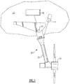
- a ram air turbine 20 is illustrated in Figure 1 .
- a strut 22 is associated with a turbine 24 and a transmission housing 26.
- Turbine 24 includes blades 18.
- the ram air turbine may be mounted to the frame of an aircraft 23, shown schematically.
- rotation of the turbine 24 generates electricity at a generator 28 in a known manner. This electricity may be used for any number of uses associated with the aircraft 27.
- the ram air turbine 20 may pivot at point 25 between a stowed position and a deployed position and driven by an actuator 11. As mentioned above, the ram air turbine may be moved to the deployed position from the stowed position when its use is desired.
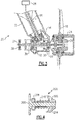
- FIG. 2A shows a detail of the ram air turbine 20.
- counterweights 29 are associated with the turbine 24.
- the counterweights control the pitch of blades 18 on the turbine 24 in response to speed.
- a transmission shaft 26 rotates with turbine 24.
- a bevel gear 32 is driven by the shaft 26 and drives an associated bevel gear 34 on an output shaft 36 in the strut 22.
- the output shaft 36 extends to the generator 28 (or other power sources, such as a pump), as known.
- governor springs 38 operate against the plate 31 and hold a governor rod 39 to the left in this figure.
- the counterweights 29 also act on the endplate 31 and against the force of the spring 38.
- a housing 37 surrounds the springs 38 and also rotates.
- the governor rod 39 is caused to move axially against the force of the governor spring 38 when the counterweights move in a direction to change the pitch angle from fine pitch to coarse pitch.
- Figure 2B schematically shows the interaction between the governor weights 20 and the governor rod 39.
- the blades 18 are held at a more open position.
- the counterweights rotate, and in turn drives the blades 18 to a more coarse position.
- Figure 2B shows this interaction, with a cam plate 103 which moves with the governor rod 39, and offset cam followers 102 which are a part of the counterweight 29 and the blades.
- a pivot axis X of the blades 108 is shown.
- the groove and cam plate 103 is part of the governor rod 39.
- the pins, which are illustrated at 100 and 102, move as the governor weights pivot.
- the governor weights 29 and blades 18 move as one such that as the pins move from the position 100 to the position 102, the angle of the blades 18 changes about the axis X.
- the associated spring positions 100S and 102S are also shown.
- the pins move from the position 100, which achieves a relatively open position of the blades 18, and as speed increases, they are moved to position 102, to pivot the blades 18 to a more closed position.
- the basic movement of the governor weights 29, blades 18, and governor rods 39 is generally as known, other than the location of the springs and addition of the governor rod, and the fact that the governor rod extends beyond the strut 22.
- the springs were on the forward end of the turbine 26 away from the strut 22.
- This arrangement located the center of gravity further from the mounting point of strut 22, and potentially diminished separation between an operating speed and a natural frequency.
- the center of gravity is optimized and the natural frequency separation is increased.
- smaller bearings and an overall reduction in mass may be achieved.
- the spring 38 mass is moved closer to the strut 22 as opposed to the prior art wherein the spring was further away. This reduces overhung mass and turbine imbalance issues that are associated with the spring changing position during governing.
- governor rod 39 extends from the turbine 24 axially beyond the output shaft 36 and the strut 22 and to a plate 31.
- the spring 38 acts against the plate 31 and is also positioned about the transmission shaft 30.
- the governor rod 39 extends along an axis which is generally co-axial to the propeller axis of rotation.
- the output shaft 36 extends along an axis which is non-perpendicular to the axis of rotation.
- Figure 3 shows an embodiment where numerals common to Figure 2A are used.
- the embodiment 100 of Figure 3 eliminates the outer housing 37 surrounding the spring 38. Endplate 31 is still used.
- the governor spring 38 acts against the plate 31, but is generally exposed radially outwardly of the transmission shaft. This has the potential benefits of making service and adjustment easier as well as reduced weight.
- Figure 4 shows yet another embodiment 200.
- the governor rod 204 extends through a fixed housing portion 202 and through the governor spring 210.
- An endplate 206 is still fixed to the rod 204.
- Bearing 208 supports the spring 210 on the plate 206 such that the spring 210 need not rotate.
- the other end of the spring is fixed to ground housing portion 202, which is a stationary portion. This may reduce issues with regard to the stability, frequency, and vibration of the ram air turbine.
Landscapes
- Engineering & Computer Science (AREA)
- Mechanical Engineering (AREA)
- Combustion & Propulsion (AREA)
- General Engineering & Computer Science (AREA)
- Chemical & Material Sciences (AREA)
- Sustainable Energy (AREA)
- Life Sciences & Earth Sciences (AREA)
- Sustainable Development (AREA)
- Aviation & Aerospace Engineering (AREA)
- Physics & Mathematics (AREA)
- Fluid Mechanics (AREA)
- Control Of Turbines (AREA)
- Connection Of Motors, Electrical Generators, Mechanical Devices, And The Like (AREA)
- Transmission Devices (AREA)
- Turbine Rotor Nozzle Sealing (AREA)
Abstract
Description
- This application relates to a ram air turbine wherein the governor springs are positioned in a unique location.
- Ram air turbines are known and typically include a turbine and blade set that is moved outwardly into an airflow path associated with an aircraft. The turbine is driven to rotate and an output shaft is driven by this rotation and utilized to generate electricity or other power.
- In one example, a ram air turbine may be selectively deployed or stowed. In such an application, the ram air turbine may be moved to the deployed position in the event of a power failure for other sources of power associated with an aircraft.
- In another application, the ram air turbine may be utilized to generate accessory electrical power. As one example, it may be utilized to provide power for a midair refueling operation.
- A ram air turbine has a governor that controls the speed with which the components are driven to rotate. Typically, counterweights and governor springs interact to provide the desired speed.
- To date, the governor springs have been co-located with the turbine positioned on a (forward) side of a strut through which the output shaft extends.
- A ram air turbine has turbine blades connected to rotate a transmission shaft. The transmission shaft is connected to drive a first gear which is engaged to drive a second gear. The second gear is connected to rotate an output shaft extending through a strut away from the transmission shaft. A governor arrangement is configured to change a pitch angle of the blades in response to speed, and includes counterweights acting on a spring in the governor arrangement. The governor spring is positioned on an opposed side of the strut relative to the turbine.
- These and other features may be best understood from the following drawings and specification.
-
-
Figure 1 schematically shows a ram air turbine. -
Figure 2A shows a detail of a ram air turbine. -
Figure 2B shows a detail schematically. -
Figure 3 shows a second embodiment. -
Figure 4 shows yet another embodiment. - A
ram air turbine 20 is illustrated inFigure 1 . As known, astrut 22 is associated with aturbine 24 and atransmission housing 26. Turbine 24 includesblades 18. The ram air turbine may be mounted to the frame of anaircraft 23, shown schematically. As known, rotation of theturbine 24 generates electricity at agenerator 28 in a known manner. This electricity may be used for any number of uses associated with theaircraft 27. - The
ram air turbine 20 may pivot atpoint 25 between a stowed position and a deployed position and driven by anactuator 11. As mentioned above, the ram air turbine may be moved to the deployed position from the stowed position when its use is desired. -
Figure 2A shows a detail of theram air turbine 20. As shown,counterweights 29 are associated with theturbine 24. The counterweights control the pitch ofblades 18 on theturbine 24 in response to speed. Atransmission shaft 26 rotates withturbine 24. Abevel gear 32 is driven by theshaft 26 and drives an associatedbevel gear 34 on anoutput shaft 36 in thestrut 22. Theoutput shaft 36 extends to the generator 28 (or other power sources, such as a pump), as known. - Governor springs 38 operate against the
plate 31 and hold agovernor rod 39 to the left in this figure. Thecounterweights 29 also act on theendplate 31 and against the force of thespring 38. Ahousing 37 surrounds thesprings 38 and also rotates. - Collectively, the
springs 38 andcounterweights 29 could be called a governor arrangement. - The
governor rod 39 is caused to move axially against the force of the governorspring 38 when the counterweights move in a direction to change the pitch angle from fine pitch to coarse pitch. -
Figure 2B schematically shows the interaction between thegovernor weights 20 and thegovernor rod 39. As can be appreciated, when the speed of theturbine 24 is low, theblades 18 are held at a more open position. As the speed increases, the counterweights rotate, and in turn drives theblades 18 to a more coarse position.Figure 2B shows this interaction, with acam plate 103 which moves with thegovernor rod 39, andoffset cam followers 102 which are a part of thecounterweight 29 and the blades. - As also shown in
Figure 2B , a pivot axis X of the blades 108 is shown. Again, the groove andcam plate 103 is part of thegovernor rod 39. The pins, which are illustrated at 100 and 102, move as the governor weights pivot. As known, thegovernor weights 29 andblades 18 move as one such that as the pins move from theposition 100 to theposition 102, the angle of theblades 18 changes about the axis X. The associatedspring positions - In
Figure 2B , the pins move from theposition 100, which achieves a relatively open position of theblades 18, and as speed increases, they are moved toposition 102, to pivot theblades 18 to a more closed position. - At any rate, the basic movement of the
governor weights 29,blades 18, andgovernor rods 39 is generally as known, other than the location of the springs and addition of the governor rod, and the fact that the governor rod extends beyond thestrut 22. - In the prior art, the springs were on the forward end of the
turbine 26 away from thestrut 22. This arrangement located the center of gravity further from the mounting point ofstrut 22, and potentially diminished separation between an operating speed and a natural frequency. By placing thesprings 38 on an opposed side of thestrut 22 and the transmission interface between thebevel gears 32/34 relative to theturbine 24, the center of gravity is optimized and the natural frequency separation is increased. In addition, smaller bearings and an overall reduction in mass may be achieved. Further, thespring 38 mass is moved closer to thestrut 22 as opposed to the prior art wherein the spring was further away. This reduces overhung mass and turbine imbalance issues that are associated with the spring changing position during governing. - Stated another way, governor
rod 39 extends from theturbine 24 axially beyond theoutput shaft 36 and thestrut 22 and to aplate 31. Thespring 38 acts against theplate 31 and is also positioned about thetransmission shaft 30. - The
governor rod 39 extends along an axis which is generally co-axial to the propeller axis of rotation. Theoutput shaft 36 extends along an axis which is non-perpendicular to the axis of rotation. -
Figure 3 shows an embodiment where numerals common toFigure 2A are used. In general, theembodiment 100 ofFigure 3 eliminates theouter housing 37 surrounding thespring 38.Endplate 31 is still used. Thegovernor spring 38 acts against theplate 31, but is generally exposed radially outwardly of the transmission shaft. This has the potential benefits of making service and adjustment easier as well as reduced weight. -
Figure 4 shows yet anotherembodiment 200. Inembodiment 200, thegovernor rod 204 extends through a fixedhousing portion 202 and through thegovernor spring 210. Anendplate 206 is still fixed to therod 204. Bearing 208 supports thespring 210 on theplate 206 such that thespring 210 need not rotate. The other end of the spring is fixed to groundhousing portion 202, which is a stationary portion. This may reduce issues with regard to the stability, frequency, and vibration of the ram air turbine. - Although an embodiment of this invention has been disclosed, a worker of ordinary skill in this art would recognize that certain modifications would come within the scope of this invention. For that reason, the following claims should be studied to determine the true scope of this invention.
Claims (11)
- A ram air turbine comprising:turbine blades (18) connected to rotate a transmission shaft (26), said transmission shaft connected for driving a first gear which is engaged to drive a second gear, said second gear connected to rotate an output shaft extending through a strut (22) away from said transmission shaft; anda governor arrangement to change a pitch angle of said blades in response to speed, and including counterweights (29) acting on a governor spring (38) in said governor arrangement, said governor spring positioned on an opposed side of said strut relative to said turbine.
- The ram air turbine as set forth in claim 1, wherein said governor spring rotates with said transmission shaft.
- The ram air turbine as set forth in claim 1 or 2, wherein said governor spring reacts off a plate (31) at an opposed end of a governor rod (39) relative to said turbine.
- The ram air turbine as set forth in claim 1, 2 or 3, wherein a housing (202) surrounds said governor spring and rotates with said transmission shaft and said governor spring.
- The ram air turbine as set forth in any preceding claim, wherein said transmission shaft extends along an axis which is generally co-axial to a rotation axis of said turbine and said output shaft extends along an axis which is non-perpendicular to said axis of said rotation.
- The ram air turbine as set forth in any preceding claim, wherein said first and second gears include a pair of bevel gears (32).
- The ram air turbine as set forth in any preceding claim, wherein said governor rod extends axially beyond said strut within said governor spring and to said plate.
- The ram air turbine as set forth in claim 3 or any claim dependent thereon, wherein said governor spring acts against said plate, but said governor spring is generally exposed radially outwardly.
- The ram air turbine as set forth in claim 1 or any of claims 3 to 8 when not dependent on claim 2, wherein said governor spring does not rotate with said transmission shaft.
- The ram air turbine as set forth in claim 3 or any claim dependent thereon, wherein said governor rod rotates with said plate and said governor spring applys a force against said plate, and a bearing supporting said governor spring on said plate.
- The ram air turbine as set forth in any preceding claim, wherein said governor rod is caused to move axially against the force of said governor spring when said counterweights move in a direction to close said pitch angle.
Applications Claiming Priority (1)
| Application Number | Priority Date | Filing Date | Title |
|---|---|---|---|
| US15/627,744 US10738761B2 (en) | 2017-06-20 | 2017-06-20 | Ram air turbine governor spring positioning |
Publications (2)
| Publication Number | Publication Date |
|---|---|
| EP3418203A1 true EP3418203A1 (en) | 2018-12-26 |
| EP3418203B1 EP3418203B1 (en) | 2022-01-12 |
Family
ID=62784008
Family Applications (1)
| Application Number | Title | Priority Date | Filing Date |
|---|---|---|---|
| EP18178827.4A Active EP3418203B1 (en) | 2017-06-20 | 2018-06-20 | Ram air turbine governor spring positioning |
Country Status (2)
| Country | Link |
|---|---|
| US (1) | US10738761B2 (en) |
| EP (1) | EP3418203B1 (en) |
Families Citing this family (2)
| Publication number | Priority date | Publication date | Assignee | Title |
|---|---|---|---|---|
| US11465769B2 (en) * | 2018-01-11 | 2022-10-11 | Hamilton Sundstrand Corporation | Electric aircraft having ram air turbines |
| US12162585B2 (en) * | 2023-03-17 | 2024-12-10 | Northrop Grumman Systems Corporation | Passive rotor pitch control system |
Citations (4)
| Publication number | Priority date | Publication date | Assignee | Title |
|---|---|---|---|---|
| US5562417A (en) * | 1994-08-10 | 1996-10-08 | Sundstrand Corporation | Control mechanism for RAM air turbine |
| US20120093653A1 (en) * | 2010-10-19 | 2012-04-19 | Hamilton Sundstrand Corporation | Turbine yokeplate flyweights to improve rat startup |
| US20120114485A1 (en) * | 2010-11-04 | 2012-05-10 | Hamilton Sundstrand Corporation | Ram air turbine startup |
| US20130287569A1 (en) * | 2012-04-27 | 2013-10-31 | David G. Bannon | Turbine lock plunger for ram air turbine assembly |
Family Cites Families (10)
| Publication number | Priority date | Publication date | Assignee | Title |
|---|---|---|---|---|
| US2550229A (en) * | 1946-08-26 | 1951-04-24 | All American Airways Inc | Air-driven impeller |
| US2815188A (en) * | 1954-01-11 | 1957-12-03 | Marquardt Aircraft Co | Auxiliary power unit |
| US2988327A (en) * | 1956-02-03 | 1961-06-13 | Plessey Co Ltd | Emergency power systems for aircraft auxiliary apparatus |
| GB1074736A (en) * | 1964-09-09 | 1967-07-05 | Dowty Rotol Ltd | Wind motors |
| US3635583A (en) | 1968-11-15 | 1972-01-18 | Dowty Rotol Ltd | Ram-air turbines |
| US4411596A (en) * | 1980-03-25 | 1983-10-25 | Sundstrand Corporation | Ram air turbine control system |
| US4743163A (en) * | 1985-11-22 | 1988-05-10 | Sundstrand Corporation | Ram air turbine control system |
| US4991796A (en) * | 1988-11-14 | 1991-02-12 | Sundstrand Corporation | Ram air turbine drive system |
| US7296970B2 (en) | 2005-06-08 | 2007-11-20 | Hamilton Sundstrand Corporation | Ram air turbine speed sensing ball detent over-speed prevention mechanism |
| US8066481B2 (en) | 2009-04-20 | 2011-11-29 | Hamilton Sundstrand Corporation | Balancing a ram air turbine |
-
2017
- 2017-06-20 US US15/627,744 patent/US10738761B2/en active Active
-
2018
- 2018-06-20 EP EP18178827.4A patent/EP3418203B1/en active Active
Patent Citations (4)
| Publication number | Priority date | Publication date | Assignee | Title |
|---|---|---|---|---|
| US5562417A (en) * | 1994-08-10 | 1996-10-08 | Sundstrand Corporation | Control mechanism for RAM air turbine |
| US20120093653A1 (en) * | 2010-10-19 | 2012-04-19 | Hamilton Sundstrand Corporation | Turbine yokeplate flyweights to improve rat startup |
| US20120114485A1 (en) * | 2010-11-04 | 2012-05-10 | Hamilton Sundstrand Corporation | Ram air turbine startup |
| US20130287569A1 (en) * | 2012-04-27 | 2013-10-31 | David G. Bannon | Turbine lock plunger for ram air turbine assembly |
Also Published As
| Publication number | Publication date |
|---|---|
| US20180363626A1 (en) | 2018-12-20 |
| US10738761B2 (en) | 2020-08-11 |
| EP3418203B1 (en) | 2022-01-12 |
Similar Documents
| Publication | Publication Date | Title |
|---|---|---|
| US20120328436A1 (en) | Electromechanical actuator driven governor for ram air turbine | |
| US20240391583A1 (en) | Propeller control system for an aircraft | |
| EP3712058B1 (en) | Combined overspeed, feathering, and reverse enabler control valve for a propeller assembly | |
| CN102448819B (en) | A movable actuator for controlling the pitch of a turboprop fan blade | |
| US9890655B2 (en) | Adjusting device for variable guide vanes and method of operation | |
| CN102448818A (en) | Device for controlling the pitch of the fan blades of a turboprop engine | |
| JP2013544204A (en) | Propeller reversing device with actuator acting on crankpin | |
| EP0247176A1 (en) | Ram air turbine control system | |
| EP3029814B1 (en) | Concentric ring generators | |
| CN112805475A (en) | Turbine engine including a rotor supporting pitch blades | |
| GB2490852A (en) | Variable-pitch mechanism for the blades of a system of contrarotary fans and system of contrarotary fans comprising at least one such mechanism | |
| US7134840B2 (en) | Rotor system for a remotely controlled aircraft | |
| EP3418203B1 (en) | Ram air turbine governor spring positioning | |
| JP2013511646A (en) | Turbine engine with variable pitch stator blade stages with independent control | |
| CN108473195A (en) | The system with feathering locking bolt for controlling turbogenerator fan blade pitch | |
| GB2492882A (en) | A device for controlling the pitch of turboprop fan blades | |
| US5286166A (en) | Automatic centrifugal force variable pitch propeller | |
| DK2908005T3 (en) | Vertical wind generator | |
| CN111661348A (en) | Thruster speed overshoot prevention logic | |
| US10036262B2 (en) | Turbomachine impellor rotor with device for feathering the blades of the impellor | |
| US20200369369A1 (en) | Fan module with variable-pitch blades for a turbomachine | |
| US11162506B2 (en) | Fan module having variable-pitch blades for a turbine engine | |
| GB2257477A (en) | Auxiliary power equipment | |
| RU2364754C1 (en) | Compressor of bypass gas-turbine engine | |
| EP3633146B1 (en) | Ram air turbine single-unit nose |
Legal Events
| Date | Code | Title | Description |
|---|---|---|---|
| PUAI | Public reference made under article 153(3) epc to a published international application that has entered the european phase |
Free format text: ORIGINAL CODE: 0009012 |
|
| STAA | Information on the status of an ep patent application or granted ep patent |
Free format text: STATUS: THE APPLICATION HAS BEEN PUBLISHED |
|
| AK | Designated contracting states |
Kind code of ref document: A1 Designated state(s): AL AT BE BG CH CY CZ DE DK EE ES FI FR GB GR HR HU IE IS IT LI LT LU LV MC MK MT NL NO PL PT RO RS SE SI SK SM TR |
|
| AX | Request for extension of the european patent |
Extension state: BA ME |
|
| STAA | Information on the status of an ep patent application or granted ep patent |
Free format text: STATUS: REQUEST FOR EXAMINATION WAS MADE |
|
| 17P | Request for examination filed |
Effective date: 20190626 |
|
| RBV | Designated contracting states (corrected) |
Designated state(s): AL AT BE BG CH CY CZ DE DK EE ES FI FR GB GR HR HU IE IS IT LI LT LU LV MC MK MT NL NO PL PT RO RS SE SI SK SM TR |
|
| STAA | Information on the status of an ep patent application or granted ep patent |
Free format text: STATUS: EXAMINATION IS IN PROGRESS |
|
| 17Q | First examination report despatched |
Effective date: 20200518 |
|
| GRAP | Despatch of communication of intention to grant a patent |
Free format text: ORIGINAL CODE: EPIDOSNIGR1 |
|
| STAA | Information on the status of an ep patent application or granted ep patent |
Free format text: STATUS: GRANT OF PATENT IS INTENDED |
|
| INTG | Intention to grant announced |
Effective date: 20210903 |
|
| RIN1 | Information on inventor provided before grant (corrected) |
Inventor name: BAINES, ANDREW N. |
|
| GRAS | Grant fee paid |
Free format text: ORIGINAL CODE: EPIDOSNIGR3 |
|
| GRAA | (expected) grant |
Free format text: ORIGINAL CODE: 0009210 |
|
| STAA | Information on the status of an ep patent application or granted ep patent |
Free format text: STATUS: THE PATENT HAS BEEN GRANTED |
|
| AK | Designated contracting states |
Kind code of ref document: B1 Designated state(s): AL AT BE BG CH CY CZ DE DK EE ES FI FR GB GR HR HU IE IS IT LI LT LU LV MC MK MT NL NO PL PT RO RS SE SI SK SM TR |
|
| REG | Reference to a national code |
Ref country code: GB Ref legal event code: FG4D |
|
| REG | Reference to a national code |
Ref country code: CH Ref legal event code: EP |
|
| REG | Reference to a national code |
Ref country code: DE Ref legal event code: R096 Ref document number: 602018029431 Country of ref document: DE |
|
| REG | Reference to a national code |
Ref country code: IE Ref legal event code: FG4D |
|
| REG | Reference to a national code |
Ref country code: AT Ref legal event code: REF Ref document number: 1462222 Country of ref document: AT Kind code of ref document: T Effective date: 20220215 |
|
| REG | Reference to a national code |
Ref country code: LT Ref legal event code: MG9D |
|
| REG | Reference to a national code |
Ref country code: NL Ref legal event code: MP Effective date: 20220112 |
|
| REG | Reference to a national code |
Ref country code: AT Ref legal event code: MK05 Ref document number: 1462222 Country of ref document: AT Kind code of ref document: T Effective date: 20220112 |
|
| PG25 | Lapsed in a contracting state [announced via postgrant information from national office to epo] |
Ref country code: NL Free format text: LAPSE BECAUSE OF FAILURE TO SUBMIT A TRANSLATION OF THE DESCRIPTION OR TO PAY THE FEE WITHIN THE PRESCRIBED TIME-LIMIT Effective date: 20220112 |
|
| PG25 | Lapsed in a contracting state [announced via postgrant information from national office to epo] |
Ref country code: SE Free format text: LAPSE BECAUSE OF FAILURE TO SUBMIT A TRANSLATION OF THE DESCRIPTION OR TO PAY THE FEE WITHIN THE PRESCRIBED TIME-LIMIT Effective date: 20220112 Ref country code: RS Free format text: LAPSE BECAUSE OF FAILURE TO SUBMIT A TRANSLATION OF THE DESCRIPTION OR TO PAY THE FEE WITHIN THE PRESCRIBED TIME-LIMIT Effective date: 20220112 Ref country code: PT Free format text: LAPSE BECAUSE OF FAILURE TO SUBMIT A TRANSLATION OF THE DESCRIPTION OR TO PAY THE FEE WITHIN THE PRESCRIBED TIME-LIMIT Effective date: 20220512 Ref country code: NO Free format text: LAPSE BECAUSE OF FAILURE TO SUBMIT A TRANSLATION OF THE DESCRIPTION OR TO PAY THE FEE WITHIN THE PRESCRIBED TIME-LIMIT Effective date: 20220412 Ref country code: LT Free format text: LAPSE BECAUSE OF FAILURE TO SUBMIT A TRANSLATION OF THE DESCRIPTION OR TO PAY THE FEE WITHIN THE PRESCRIBED TIME-LIMIT Effective date: 20220112 Ref country code: HR Free format text: LAPSE BECAUSE OF FAILURE TO SUBMIT A TRANSLATION OF THE DESCRIPTION OR TO PAY THE FEE WITHIN THE PRESCRIBED TIME-LIMIT Effective date: 20220112 Ref country code: ES Free format text: LAPSE BECAUSE OF FAILURE TO SUBMIT A TRANSLATION OF THE DESCRIPTION OR TO PAY THE FEE WITHIN THE PRESCRIBED TIME-LIMIT Effective date: 20220112 Ref country code: BG Free format text: LAPSE BECAUSE OF FAILURE TO SUBMIT A TRANSLATION OF THE DESCRIPTION OR TO PAY THE FEE WITHIN THE PRESCRIBED TIME-LIMIT Effective date: 20220412 |
|
| PG25 | Lapsed in a contracting state [announced via postgrant information from national office to epo] |
Ref country code: PL Free format text: LAPSE BECAUSE OF FAILURE TO SUBMIT A TRANSLATION OF THE DESCRIPTION OR TO PAY THE FEE WITHIN THE PRESCRIBED TIME-LIMIT Effective date: 20220112 Ref country code: LV Free format text: LAPSE BECAUSE OF FAILURE TO SUBMIT A TRANSLATION OF THE DESCRIPTION OR TO PAY THE FEE WITHIN THE PRESCRIBED TIME-LIMIT Effective date: 20220112 Ref country code: GR Free format text: LAPSE BECAUSE OF FAILURE TO SUBMIT A TRANSLATION OF THE DESCRIPTION OR TO PAY THE FEE WITHIN THE PRESCRIBED TIME-LIMIT Effective date: 20220413 Ref country code: FI Free format text: LAPSE BECAUSE OF FAILURE TO SUBMIT A TRANSLATION OF THE DESCRIPTION OR TO PAY THE FEE WITHIN THE PRESCRIBED TIME-LIMIT Effective date: 20220112 Ref country code: AT Free format text: LAPSE BECAUSE OF FAILURE TO SUBMIT A TRANSLATION OF THE DESCRIPTION OR TO PAY THE FEE WITHIN THE PRESCRIBED TIME-LIMIT Effective date: 20220112 |
|
| PG25 | Lapsed in a contracting state [announced via postgrant information from national office to epo] |
Ref country code: IS Free format text: LAPSE BECAUSE OF FAILURE TO SUBMIT A TRANSLATION OF THE DESCRIPTION OR TO PAY THE FEE WITHIN THE PRESCRIBED TIME-LIMIT Effective date: 20220512 |
|
| REG | Reference to a national code |
Ref country code: DE Ref legal event code: R097 Ref document number: 602018029431 Country of ref document: DE |
|
| PG25 | Lapsed in a contracting state [announced via postgrant information from national office to epo] |
Ref country code: SM Free format text: LAPSE BECAUSE OF FAILURE TO SUBMIT A TRANSLATION OF THE DESCRIPTION OR TO PAY THE FEE WITHIN THE PRESCRIBED TIME-LIMIT Effective date: 20220112 Ref country code: SK Free format text: LAPSE BECAUSE OF FAILURE TO SUBMIT A TRANSLATION OF THE DESCRIPTION OR TO PAY THE FEE WITHIN THE PRESCRIBED TIME-LIMIT Effective date: 20220112 Ref country code: RO Free format text: LAPSE BECAUSE OF FAILURE TO SUBMIT A TRANSLATION OF THE DESCRIPTION OR TO PAY THE FEE WITHIN THE PRESCRIBED TIME-LIMIT Effective date: 20220112 Ref country code: EE Free format text: LAPSE BECAUSE OF FAILURE TO SUBMIT A TRANSLATION OF THE DESCRIPTION OR TO PAY THE FEE WITHIN THE PRESCRIBED TIME-LIMIT Effective date: 20220112 Ref country code: DK Free format text: LAPSE BECAUSE OF FAILURE TO SUBMIT A TRANSLATION OF THE DESCRIPTION OR TO PAY THE FEE WITHIN THE PRESCRIBED TIME-LIMIT Effective date: 20220112 Ref country code: CZ Free format text: LAPSE BECAUSE OF FAILURE TO SUBMIT A TRANSLATION OF THE DESCRIPTION OR TO PAY THE FEE WITHIN THE PRESCRIBED TIME-LIMIT Effective date: 20220112 |
|
| PLBE | No opposition filed within time limit |
Free format text: ORIGINAL CODE: 0009261 |
|
| STAA | Information on the status of an ep patent application or granted ep patent |
Free format text: STATUS: NO OPPOSITION FILED WITHIN TIME LIMIT |
|
| PG25 | Lapsed in a contracting state [announced via postgrant information from national office to epo] |
Ref country code: AL Free format text: LAPSE BECAUSE OF FAILURE TO SUBMIT A TRANSLATION OF THE DESCRIPTION OR TO PAY THE FEE WITHIN THE PRESCRIBED TIME-LIMIT Effective date: 20220112 |
|
| 26N | No opposition filed |
Effective date: 20221013 |
|
| PG25 | Lapsed in a contracting state [announced via postgrant information from national office to epo] |
Ref country code: MC Free format text: LAPSE BECAUSE OF FAILURE TO SUBMIT A TRANSLATION OF THE DESCRIPTION OR TO PAY THE FEE WITHIN THE PRESCRIBED TIME-LIMIT Effective date: 20220112 |
|
| REG | Reference to a national code |
Ref country code: CH Ref legal event code: PL |
|
| REG | Reference to a national code |
Ref country code: BE Ref legal event code: MM Effective date: 20220630 |
|
| PG25 | Lapsed in a contracting state [announced via postgrant information from national office to epo] |
Ref country code: SI Free format text: LAPSE BECAUSE OF FAILURE TO SUBMIT A TRANSLATION OF THE DESCRIPTION OR TO PAY THE FEE WITHIN THE PRESCRIBED TIME-LIMIT Effective date: 20220112 |
|
| PG25 | Lapsed in a contracting state [announced via postgrant information from national office to epo] |
Ref country code: LU Free format text: LAPSE BECAUSE OF NON-PAYMENT OF DUE FEES Effective date: 20220620 Ref country code: LI Free format text: LAPSE BECAUSE OF NON-PAYMENT OF DUE FEES Effective date: 20220630 Ref country code: IE Free format text: LAPSE BECAUSE OF NON-PAYMENT OF DUE FEES Effective date: 20220620 Ref country code: CH Free format text: LAPSE BECAUSE OF NON-PAYMENT OF DUE FEES Effective date: 20220630 |
|
| PG25 | Lapsed in a contracting state [announced via postgrant information from national office to epo] |
Ref country code: BE Free format text: LAPSE BECAUSE OF NON-PAYMENT OF DUE FEES Effective date: 20220630 |
|
| P01 | Opt-out of the competence of the unified patent court (upc) registered |
Effective date: 20230522 |
|
| PG25 | Lapsed in a contracting state [announced via postgrant information from national office to epo] |
Ref country code: IT Free format text: LAPSE BECAUSE OF FAILURE TO SUBMIT A TRANSLATION OF THE DESCRIPTION OR TO PAY THE FEE WITHIN THE PRESCRIBED TIME-LIMIT Effective date: 20220112 |
|
| PG25 | Lapsed in a contracting state [announced via postgrant information from national office to epo] |
Ref country code: HU Free format text: LAPSE BECAUSE OF FAILURE TO SUBMIT A TRANSLATION OF THE DESCRIPTION OR TO PAY THE FEE WITHIN THE PRESCRIBED TIME-LIMIT; INVALID AB INITIO Effective date: 20180620 |
|
| PG25 | Lapsed in a contracting state [announced via postgrant information from national office to epo] |
Ref country code: MK Free format text: LAPSE BECAUSE OF FAILURE TO SUBMIT A TRANSLATION OF THE DESCRIPTION OR TO PAY THE FEE WITHIN THE PRESCRIBED TIME-LIMIT Effective date: 20220112 Ref country code: CY Free format text: LAPSE BECAUSE OF FAILURE TO SUBMIT A TRANSLATION OF THE DESCRIPTION OR TO PAY THE FEE WITHIN THE PRESCRIBED TIME-LIMIT Effective date: 20220112 |
|
| PG25 | Lapsed in a contracting state [announced via postgrant information from national office to epo] |
Ref country code: TR Free format text: LAPSE BECAUSE OF FAILURE TO SUBMIT A TRANSLATION OF THE DESCRIPTION OR TO PAY THE FEE WITHIN THE PRESCRIBED TIME-LIMIT Effective date: 20220112 |
|
| PG25 | Lapsed in a contracting state [announced via postgrant information from national office to epo] |
Ref country code: MT Free format text: LAPSE BECAUSE OF FAILURE TO SUBMIT A TRANSLATION OF THE DESCRIPTION OR TO PAY THE FEE WITHIN THE PRESCRIBED TIME-LIMIT Effective date: 20220112 |
|
| PGFP | Annual fee paid to national office [announced via postgrant information from national office to epo] |
Ref country code: DE Payment date: 20250520 Year of fee payment: 8 |
|
| PGFP | Annual fee paid to national office [announced via postgrant information from national office to epo] |
Ref country code: GB Payment date: 20250520 Year of fee payment: 8 |
|
| PGFP | Annual fee paid to national office [announced via postgrant information from national office to epo] |
Ref country code: FR Payment date: 20250520 Year of fee payment: 8 |