EP3418122A1 - Position change determination device, overhead view image generation device, overhead view image generation system, position change determination method, and program - Google Patents
Position change determination device, overhead view image generation device, overhead view image generation system, position change determination method, and program Download PDFInfo
- Publication number
- EP3418122A1 EP3418122A1 EP17812907.8A EP17812907A EP3418122A1 EP 3418122 A1 EP3418122 A1 EP 3418122A1 EP 17812907 A EP17812907 A EP 17812907A EP 3418122 A1 EP3418122 A1 EP 3418122A1
- Authority
- EP
- European Patent Office
- Prior art keywords
- periphery
- posture
- image
- vehicle
- imaging camera
- Prior art date
- Legal status (The legal status is an assumption and is not a legal conclusion. Google has not performed a legal analysis and makes no representation as to the accuracy of the status listed.)
- Granted
Links
Images




Classifications
-
- G—PHYSICS
- G06—COMPUTING OR CALCULATING; COUNTING
- G06T—IMAGE DATA PROCESSING OR GENERATION, IN GENERAL
- G06T7/00—Image analysis
- G06T7/70—Determining position or orientation of objects or cameras
- G06T7/73—Determining position or orientation of objects or cameras using feature-based methods
- G06T7/74—Determining position or orientation of objects or cameras using feature-based methods involving reference images or patches
-
- B—PERFORMING OPERATIONS; TRANSPORTING
- B60—VEHICLES IN GENERAL
- B60R—VEHICLES, VEHICLE FITTINGS, OR VEHICLE PARTS, NOT OTHERWISE PROVIDED FOR
- B60R1/00—Optical viewing arrangements; Real-time viewing arrangements for drivers or passengers using optical image capturing systems, e.g. cameras or video systems specially adapted for use in or on vehicles
- B60R1/20—Real-time viewing arrangements for drivers or passengers using optical image capturing systems, e.g. cameras or video systems specially adapted for use in or on vehicles
- B60R1/22—Real-time viewing arrangements for drivers or passengers using optical image capturing systems, e.g. cameras or video systems specially adapted for use in or on vehicles for viewing an area outside the vehicle, e.g. the exterior of the vehicle
- B60R1/23—Real-time viewing arrangements for drivers or passengers using optical image capturing systems, e.g. cameras or video systems specially adapted for use in or on vehicles for viewing an area outside the vehicle, e.g. the exterior of the vehicle with a predetermined field of view
- B60R1/27—Real-time viewing arrangements for drivers or passengers using optical image capturing systems, e.g. cameras or video systems specially adapted for use in or on vehicles for viewing an area outside the vehicle, e.g. the exterior of the vehicle with a predetermined field of view providing all-round vision, e.g. using omnidirectional cameras
-
- G—PHYSICS
- G06—COMPUTING OR CALCULATING; COUNTING
- G06T—IMAGE DATA PROCESSING OR GENERATION, IN GENERAL
- G06T3/00—Geometric image transformations in the plane of the image
- G06T3/40—Scaling of whole images or parts thereof, e.g. expanding or contracting
- G06T3/4038—Image mosaicing, e.g. composing plane images from plane sub-images
-
- G—PHYSICS
- G06—COMPUTING OR CALCULATING; COUNTING
- G06T—IMAGE DATA PROCESSING OR GENERATION, IN GENERAL
- G06T7/00—Image analysis
- G06T7/20—Analysis of motion
-
- G—PHYSICS
- G06—COMPUTING OR CALCULATING; COUNTING
- G06T—IMAGE DATA PROCESSING OR GENERATION, IN GENERAL
- G06T7/00—Image analysis
- G06T7/20—Analysis of motion
- G06T7/246—Analysis of motion using feature-based methods, e.g. the tracking of corners or segments
-
- G—PHYSICS
- G06—COMPUTING OR CALCULATING; COUNTING
- G06V—IMAGE OR VIDEO RECOGNITION OR UNDERSTANDING
- G06V20/00—Scenes; Scene-specific elements
- G06V20/50—Context or environment of the image
- G06V20/56—Context or environment of the image exterior to a vehicle by using sensors mounted on the vehicle
-
- H—ELECTRICITY
- H04—ELECTRIC COMMUNICATION TECHNIQUE
- H04N—PICTORIAL COMMUNICATION, e.g. TELEVISION
- H04N7/00—Television systems
- H04N7/18—Closed-circuit television [CCTV] systems, i.e. systems in which the video signal is not broadcast
- H04N7/181—Closed-circuit television [CCTV] systems, i.e. systems in which the video signal is not broadcast for receiving images from a plurality of remote sources
-
- B—PERFORMING OPERATIONS; TRANSPORTING
- B60—VEHICLES IN GENERAL
- B60R—VEHICLES, VEHICLE FITTINGS, OR VEHICLE PARTS, NOT OTHERWISE PROVIDED FOR
- B60R2300/00—Details of viewing arrangements using cameras and displays, specially adapted for use in a vehicle
- B60R2300/10—Details of viewing arrangements using cameras and displays, specially adapted for use in a vehicle characterised by the type of camera system used
- B60R2300/105—Details of viewing arrangements using cameras and displays, specially adapted for use in a vehicle characterised by the type of camera system used using multiple cameras
-
- B—PERFORMING OPERATIONS; TRANSPORTING
- B60—VEHICLES IN GENERAL
- B60R—VEHICLES, VEHICLE FITTINGS, OR VEHICLE PARTS, NOT OTHERWISE PROVIDED FOR
- B60R2300/00—Details of viewing arrangements using cameras and displays, specially adapted for use in a vehicle
- B60R2300/40—Details of viewing arrangements using cameras and displays, specially adapted for use in a vehicle characterised by the details of the power supply or the coupling to vehicle components
-
- B—PERFORMING OPERATIONS; TRANSPORTING
- B60—VEHICLES IN GENERAL
- B60R—VEHICLES, VEHICLE FITTINGS, OR VEHICLE PARTS, NOT OTHERWISE PROVIDED FOR
- B60R2300/00—Details of viewing arrangements using cameras and displays, specially adapted for use in a vehicle
- B60R2300/60—Details of viewing arrangements using cameras and displays, specially adapted for use in a vehicle characterised by monitoring and displaying vehicle exterior scenes from a transformed perspective
- B60R2300/607—Details of viewing arrangements using cameras and displays, specially adapted for use in a vehicle characterised by monitoring and displaying vehicle exterior scenes from a transformed perspective from a bird's eye viewpoint
-
- G—PHYSICS
- G06—COMPUTING OR CALCULATING; COUNTING
- G06T—IMAGE DATA PROCESSING OR GENERATION, IN GENERAL
- G06T2207/00—Indexing scheme for image analysis or image enhancement
- G06T2207/30—Subject of image; Context of image processing
- G06T2207/30244—Camera pose
-
- G—PHYSICS
- G06—COMPUTING OR CALCULATING; COUNTING
- G06T—IMAGE DATA PROCESSING OR GENERATION, IN GENERAL
- G06T2207/00—Indexing scheme for image analysis or image enhancement
- G06T2207/30—Subject of image; Context of image processing
- G06T2207/30248—Vehicle exterior or interior
-
- G—PHYSICS
- G06—COMPUTING OR CALCULATING; COUNTING
- G06T—IMAGE DATA PROCESSING OR GENERATION, IN GENERAL
- G06T2207/00—Indexing scheme for image analysis or image enhancement
- G06T2207/30—Subject of image; Context of image processing
- G06T2207/30248—Vehicle exterior or interior
- G06T2207/30252—Vehicle exterior; Vicinity of vehicle
-
- G—PHYSICS
- G06—COMPUTING OR CALCULATING; COUNTING
- G06T—IMAGE DATA PROCESSING OR GENERATION, IN GENERAL
- G06T2207/00—Indexing scheme for image analysis or image enhancement
- G06T2207/30—Subject of image; Context of image processing
- G06T2207/30248—Vehicle exterior or interior
- G06T2207/30252—Vehicle exterior; Vicinity of vehicle
- G06T2207/30256—Lane; Road marking
Definitions
- FIG. 1 is a block diagram illustrating a configuration example of a bird's-eye-view-image generating system according to a first embodiment.
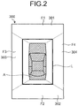
- FIG. 2 illustrates a bird's-eye view image that is generated by the bird's-eye-view-image generating system according to the first embodiment.
- FIG. 3 is a plan view explaining a posture of a vehicle that uses the bird's-eye-view-image generating system according to the first embodiment.
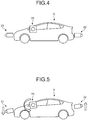
- FIG. 4 is a side view explaining a posture of a vehicle that uses the bird's-eye-view-image generating system according to the first embodiment.
- FIG. 5 is a side view explaining a posture of a vehicle that uses the bird's-eye-view-image generating system according to the first embodiment.
- the vehicle-information acquiring unit 42 is connected to the CAN installed in the vehicle V and acquires OBD (on board diagnosis) II data and the like, thereby acquiring various kinds of information about the vehicle V.
- the vehicle-information acquiring unit 42 acquires, for example, shift position information and vehicle speed information as the information about the vehicle V.
- the vehicle-information acquiring unit 42 outputs the acquired vehicle information to the control unit 43.
- the posture-change determining unit 44 determines whether the posture of the vehicle V has changed based on the variations of the tilt angle ⁇ X1 to the tilt angle ⁇ X4 of the periphery imaging camera 21 to the periphery imaging camera 24, the variations of the height y1 to the height y4, the variations of the rotation angle ⁇ Z1 to the rotation angle ⁇ Z4 based on multiple periphery images that are acquired by the image acquiring unit 41.
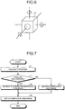
- FIG. 7 is a flowchart illustrating a flow of processing by the posture-change determining device and the bird's-eye-view-image generating device of the bird's-eye-view-image generating system according to the first embodiment.
- the imaged object 211, the imaged object 212, and the imaged object 213 are lanes.
- the imaged object 214 is a curbstone.
- the image object 215 is a side wall.
- the control unit 43 causes the posture-change determining unit 44 to extend straight lines corresponding to the imaged object 211, the imaged object 212, the imaged object 213, the imaged object 214, and the imaged object 215 in the periphery image 201.
- the control unit 43 then causes the posture-change determining unit 44 to identify an intersection of the straight lines as a vanishing point PA of the periphery image 201.
- the control unit 43 causes the posture-change determining unit 44 to identify a vanishing point PB of the periphery image 202 illustrated in FIG. 9 similarly.
- the control unit 43 performs this processing respectively for the rearward-periphery imaging camera 22, the leftward-periphery imaging camera 23, and the rightward-periphery imaging camera 24, and acquires a variation of the tilt angle ⁇ X2 of the rearward-periphery imaging camera 22, a variation of the tilt angle ⁇ X3 of the leftward-periphery imaging camera 23, and a variation of the tilt angle ⁇ X4 of the rightward-periphery imaging camera 24.
- the control unit 43 causes the posture-change determining unit 44 to calculate the variation of rotation angle ⁇ Z4 of the rightward-periphery imaging camera 24 based on at least either set of the variation of the tilt angle ⁇ X1 and the variation of the height y1 of the forward-periphery imaging camera 21, and the variation of the tilt angle ⁇ X2 and the variation of the height y2 of the rearward-periphery imaging camera 22.
- the control unit 43 proceeds to step S3 when the posture-change determining unit 44 determines that the posture has not changed (NO at step S2).
- the control unit 43 proceeds to step S4 when the posture-change determining unit 44 determines that the posture has changed (YES at step S2).
- the vehicle-information acquiring unit 42 is connected to the CAN provided in the vehicle V and acquires the OBD II data or the like, thereby acquiring the shift position information of the vehicle V and the vehicle speed information of the vehicle V.
- the control unit 43 excludes movement vector components that are based on travel of the vehicle V when extracting movement vector based on periphery images captured at predetermined frame intervals, and thus extracts only movement vector corresponding to a change in height of the forward-periphery imaging camera 21. Movement vectors based on parallel movement in the horizontal direction of the vehicle V are different in direction from movement vector when images make parallel movement in the height direction along with movement of the camera in the height direction (vertical direction). Therefore, when extracting movement vectors based on periphery images captured at predetermined frame intervals, components of the movement vectors based on travel of the vehicle V can be easily removed. Alternatively, movement vectors based on travel of the vehicle V can be calculated based on the vehicle speed acquired by the vehicle-information acquiring unit 42.
- the control unit 43 can acquire variations of the tilt angle ⁇ X1 to the tilt angle ⁇ X4 of the periphery imaging camera 21 to the periphery imaging camera 24, for example, based on a change of a position of convergence lines (convergent position) at which the contact ground surface of the vehicle V converges at infinity in periphery images captured by the periphery imaging camera 21 to the periphery imaging camera 24.
- the convergence line is, for example, the horizon or the skyline.
Landscapes
- Engineering & Computer Science (AREA)
- Multimedia (AREA)
- Physics & Mathematics (AREA)
- General Physics & Mathematics (AREA)
- Theoretical Computer Science (AREA)
- Computer Vision & Pattern Recognition (AREA)
- Mechanical Engineering (AREA)
- Signal Processing (AREA)
- Closed-Circuit Television Systems (AREA)
- Image Analysis (AREA)
- Image Processing (AREA)
- Fittings On The Vehicle Exterior For Carrying Loads, And Devices For Holding Or Mounting Articles (AREA)
Abstract
Description
- The present invention relates to a posture-change determining device, a bird's-eye-view image generating device, a bird's-eye-view image generating system, a posture-change determining method, and a program. Background
- A technique of capturing images around a vehicle with cameras mounted around a vehicle, and of displaying captured images subjected to eye point conversion on a monitor as a bird's eye view has been known (for example, refer to Patent Literature 1). This technique achieves acquisition of a monitor image with favorable image quality even with variation in height or inclination change of a vehicle on which an on-vehicle camera is mounted.
- Patent Literature 1: Japanese Laid-open Patent Publication No.
2009-253571 - The technique described in Patent Literature 1 requires a sensor that detects a sinking amount of a suspension to be arranged at each wheel, to measure a change in height and a change in inclination of a vehicle. Therefore, a technique of appropriately determining a posture change of a vehicle without using a sensor, supporting also a posture change of the vehicle that is not reflected in sinking of suspensions and the like, and a technique of generating a bird's-eye view image coping with a change of posture of a vehicle have been demanded.
- The present invention is achieved in view of the above challenge, and it is an object to provide a technique, easily applicable to a vehicle without using a sensor, of determining a change of posture of a vehicle appropriately when the posture of the vehicle changes and of providing a bird's-eye view image around the vehicle corrected appropriately based on a result of the determination. Solution to Problem
- To solve the above challenge and achieve the object, a posture-change determining device according to the present invention includes an image acquiring unit that acquires a plurality of periphery images in which a periphery of a vehicle is imaged by a plurality of imaging devices that are provided in the vehicle, and a posture-change determining unit that determines whether a posture of the vehicle has changed based on the periphery images that are acquired by the image acquiring unit.
- A bird's-eye-view-image generating device according to the present invention includes the posture-change determining device described above, and a bird's-eye-view-image generating unit that generates a bird's-eye view image obtained by combining a plurality of periphery images acquired by the image acquiring unit subjected to eye point conversion so that an image looking the vehicle down from above is obtained. The bird's-eye-view-image generating unit generates a bird's-eye view image that is corrected according to a change of a posture of the vehicle based on a determination result of the posture-change determining unit.
- A bird's-eye-view-image generating system according to the present invention includes the bird's-eye-view-image generating device described above, and an imaging device that is arranged in the vehicle and that images a periphery of the vehicle and provides a periphery image to the image acquiring unit.
- A posture-change determining method according to the present invention, includes an image acquiring step of acquiring a plurality of periphery images in which a periphery of a vehicle is imaged by a plurality of imaging devices that are provided in the vehicle, and a determining step of determining whether a posture of the vehicle has changed based on the periphery images that are acquired at the image acquiring step.
- A program that causes a computer to operate as a posture-change determining device is disclosed. The program according to the present invention includes an image acquiring step of acquiring a plurality of periphery images in which a periphery of a vehicle is imaged by a plurality of imaging devices that are provided in the vehicle, and a determining step of determining whether a posture of the vehicle has changed based on the periphery images that are acquired at the image acquiring step. Advantageous Effects of Invention
- According to the present invention, effects are produced that it is applicable easily to a vehicle without using a sensor, and that appropriate determination of a change of posture of the vehicle when the posture of the vehicle changes and provision of a bird's-eye view image around the vehicle appropriately corrected based on a result of determination are enabled.
-
-
FIG. 1 is a block diagram illustrating a configuration example of a bird's-eye-view-image generating system according to a first embodiment. -
FIG. 2 illustrates a bird's-eye view image that is generated by the bird's-eye-view-image generating system according to the first embodiment. -
FIG. 3 is a plan view explaining a posture of a vehicle that uses the bird's-eye-view-image generating system according to the first embodiment. -
FIG. 4 is a side view explaining a posture of a vehicle that uses the bird's-eye-view-image generating system according to the first embodiment. -
FIG. 5 is a side view explaining a posture of a vehicle that uses the bird's-eye-view-image generating system according to the first embodiment. -
FIG. 6 is a schematic diagram explaining a posture of a forward-periphery imaging camera of the bird's-eye-view-image generating system according to the first embodiment. -
FIG. 7 is a flowchart illustrating a flow of processing by a posture-change determining device and a bird's-eye-view-image generating device of the bird's-eye-view-image generating system according to the first embodiment. -
FIG. 8 illustrates one example of an image captured by the forward-periphery imaging camera of the bird's-eye-view-image generating system according to the first embodiment. -
FIG. 9 illustrates another example of an image captured by the forward-periphery imaging camera of the bird's-eye-view-image generating system according to the first embodiment. -
FIG. 10 illustrates another example of an image captured by the forward-periphery imaging camera of the bird's-eye-view-image generating system according to the first embodiment. -
FIG. 11 illustrates another example of an image captured by the forward-periphery imaging camera of the bird's-eye-view-image generating system according to the first embodiment. -
FIG. 12 is a schematic diagram explaining a movement vector. -
FIG. 13 illustrates a conventional bird's-eye view image. - Embodiments of a posture-change determining device, a bird's-eye-view-image generating device, a bird's-eye-view-image generating system, a posture-change determining method, and a program according to the present invention are explained in detail below, referring to the accompanying drawings. The following embodiments are not intended to limit the present invention.
-
FIG. 1 is a block diagram illustrating a configuration example of a bird's-eye-view-image generating system according to a first embodiment.FIG. 2 illustrates a bird's-eye view image that is generated by the bird's-eye-view-image generating system according to the first embodiment.FIG. 3 is a plan view explaining a posture of a vehicle that uses the bird's-eye-view-image generating system according to the first embodiment.FIG. 4 is a side view explaining a posture of a vehicle that uses the bird's-eye-view-image generating system according to the first embodiment.FIG. 5 is a side view explaining a posture of a vehicle that uses the bird's-eye-view-image generating system according to the first embodiment. A bird's-eye-view-image generating system 10 generates a composite image of periphery of a vehicle V (refer toFIG. 3 orFIG. 5 ). In the present embodiment, the bird's-eye-view-image generating system 10 generates a bird's-eye view image 300 (refer toFIG. 2 ) of the vehicle V. In the present embodiment, a bird's-eye view image generated by the bird's-eye-view-image generating system 10 is explained as the bird's-eye view image 300 that includes a virtual own-vehicle image A expressing the vehicle V, looking the vehicle V down from above as illustrated inFIG. 2 . The present embodiment is applicable to any of a state of displaying the bird's-eye view image 300 when the vehicle V is traveling forward or backward and a state of displaying the bird's-eye view image 300 during a stop when the vehicle speed is zero. - The bird's-eye-view-
image generating system 10 is explained by usingFIG. 1 . When determining that a posture of the vehicle V has changed, the bird's-eye-view-image generating system 10 generates the bird's-eye view image 300 corrected according to the change in the posture of the vehicle V. Besides one that has been installed in the vehicle V, the bird's-eye-view-image generating system 10 can be a portable device that can be used in the vehicle V also. - The bird's-eye-view-
image generating system 10 is mounted on the vehicle V, and is connected to a display panel 101 that displays images based on processing by a display control unit 46 so as to be able to transmit an image signal thereto. The bird's-eye-view-image generating system 10 is connected such that data related to the vehicle V can be received using a CAN (controller area network) and the like from the vehicle V. In the present embodiment, the display panel 101 is not included in the bird's-eye-view-image generating system 10, but can be included therein. - The display panel 101 is a display including, for example, a liquid crystal display (LCD) and an organic EL (electro-luminescence) display. The display panel 101 displays the bird's-
eye view image 300 based on an image signal that is output from the display control unit 46 of a bird's-eye-view-image generating device 40 of the bird's-eye-view-image generating system 10. The display panel 101 can be one dedicated to the bird's-eye-view-image generating system 10, or can be one shared with another system including, for example, a navigation system. The display panel 101 is arranged at a position that is easily seen by a viewer including a driver. - The bird's-eye-view-
image generating system 10 includes a forward-periphery imaging camera (imaging device) 21, a rearward-periphery imaging camera (imaging device) 22, a leftward-periphery imaging camera (imaging device) 23, a rightward-periphery imaging camera (imaging device) 24, a storage device 30, the bird's-eye-view-image generating device 40, and a posture-change determining device 50. - The forward-
periphery imaging camera 21, the rearward-periphery imaging camera 22, the leftward-periphery imaging camera 23, and the rightward-periphery imaging camera 24 (hereinafter, "theperiphery imaging camera 21 to theperiphery imaging camera 24") are explained, usingFIG. 3 to FIG. 5 . InFIG. 3 to FIG. 5 , the forward-periphery imaging camera 21, the leftward-periphery imaging camera 23, and the rightward-periphery imaging camera 24 are illustrated in an emphasized manner. While the respective cameras inFIG. 3 to FIG. 5 are illustrated to direct toward the horizontal direction to facilitate explanation, the cameras are directed to be able to image mainly a lower part of the periphery of the vehicle V in respective directions in an actual situation. - The forward-
periphery imaging camera 21 is arranged on a front of the vehicle V and images mainly a frontward periphery of the vehicle V. The forward-periphery imaging camera 21 is fixed to the vehicle V. In other words, the position and the posture of the forward-periphery imaging camera 21 relative to the vehicle V are fixed. Therefore, when the posture of the vehicle V relative to a contact ground surface including a surface of the ground and a surface of a floor changes, the posture of the forward-periphery imaging camera 21 relative to the contact ground surface changes. InFIG. 4 , a vehicle axis of the vehicle V does not tilt to the contact ground surface, but extends along a direction parallel thereto. In this case, an optical axis of the forward-periphery imaging camera 21 extends along a direction parallel to the contact ground surface. The state illustrated inFIG. 4 is regarded as a reference state. InFIG. 5 , the vehicle axis of the vehicle V extends in a tilted manner lowering from a rear side toward a front side relative to the contact ground surface. In this case, the optical axis of the forward-periphery imaging camera 21 extends in a tilted manner lowering from the rear side toward the front side relative to the contact ground surface. - The posture of the forward-
periphery imaging camera 21 is explained, usingFIG. 6. FIG. 6 is a schematic diagram explaining a posture of the forward-periphery imaging camera of the bird's-eye-view-image generating system according to the first embodiment. In a coordinate system of the forward-periphery imaging camera 21, an optical axis direction of the forward-periphery imaging camera 21 is a Z axis, and directions perpendicular to the Z axis are an X axis and a Y axis, and a center of the forward-periphery imaging camera 21 is the origin point of the coordinate system. The posture of the forward-periphery imaging camera 21 is identified by six axes of coordinates (x1, y1, z1) and rotation components about the X axis, the Y axis, and the Z axis (θX1, θY1, θZ1). In the present embodiment, a tilt angle θX1, which is the rotation component about the X axis, a height y1 in the direction of the Y axis indicating a height from the contact ground surface, and a rotation angle θZ1, which is a rotation component about the Z axis vary in the forward-periphery imaging camera 21. - In the forward-
periphery imaging camera 21, an angle of view in the horizontal direction is, for example, 120° to 190°, and an angle of view in the vertical direction is, for example, 90° to 120°. In the present embodiment, imaging conditions including the angle of view of the forward-periphery imaging camera 21 are fixed. The forward-periphery imaging camera 21 outputs a captured periphery image to animage acquiring unit 41 of the bird's-eye-view-image generating device 40. The periphery image acquired by the forward-periphery imaging camera 21 is, for example, image data of successive images of 60 frames per second. - The rearward-
periphery imaging camera 22 is arranged on a back of the vehicle V and images mainly a rearward periphery of the vehicle V. The rearward-periphery imaging camera 22 is fixed to the vehicle V. In other words, the position and the posture of the rearward-periphery imaging camera 22 relative to the vehicle V are fixed. Therefore, when the posture of the vehicle V relative to a contact ground surface including a surface of the ground and a surface of a floor changes, the posture of the rearward-periphery imaging camera 22 relative to the contact ground surface changes. - The posture of the rearward-
periphery imaging camera 22 is identified by six axes of coordinates (x2, y2, z2) and rotation components about the X axis, the Y axis, and the Z axis (θX2, θY2, θZ2), using an optical axis direction of the rearward-periphery imaging camera 22 as a Z axis, directions perpendicular to the Z axis are an X axis and a Y axis, and a center of the rearward-periphery imaging camera 22 as the origin point of the coordinate system. In the present embodiment, a tilt angle θX2, which is the rotation component about the X axis, a height y2 in the direction of the Y axis indicating a height from the contact ground surface, and a rotation angle θZ2, which is a rotation component about the Z axis, vary in the rearward-periphery imaging camera 22. - In the rearward-
periphery imaging camera 22, an angle of view in the horizontal direction is, for example, 120° to 190°, and an angle of view in the vertical direction is, for example, 90° to 120°. The rearward-periphery imaging camera 22 outputs a captured periphery image to theimage acquiring unit 41 of the bird's-eye-view-image generating device 40. The periphery image acquired by the rearward-periphery imaging camera 22 is, for example, image data of successive images of 60 frames per second. - The leftward-
periphery imaging camera 23 is arranged on a left side of the vehicle V and images a periphery mainly on a left side of the vehicle V. The leftward-periphery imaging camera 23 is fixed to the vehicle V. In other words, the position and the posture of the leftward-periphery imaging camera 23 relative to the vehicle V are fixed. Therefore, when the posture of the vehicle V relative to a contact ground surface including a surface of the ground and a surface of a floor changes, the posture of the leftward-periphery imaging camera 23 relative to the contact ground surface changes. - The posture of the leftward-
periphery imaging camera 23 is identified by six axes of coordinates (x3, y3, z3) and rotation components about the X axis, the Y axis, and the Z axis (θX3, θY3, θZ3), using an optical axis direction of the leftward-periphery imaging camera 23 as a Z axis, directions perpendicular to the Z axis are an X axis and a Y axis, and a center of the leftward-periphery imaging camera 23 as the origin point of the coordinate system. In the present embodiment, a tilt angle θX3, which is the rotation component about the X axis, a height y3 in the direction of the Y axis indicating a height from the contact ground surface, and a rotation angle θZ3, which is a rotation component about the Z axis, vary in the leftward-periphery imaging camera 23. - In the leftward-
periphery imaging camera 23, an angle of view in the horizontal direction is, for example, 120° to 190°, and an angle of view in the vertical direction is, for example, 90° to 120°. The leftward-periphery imaging camera 23 outputs a captured periphery image to theimage acquiring unit 41 of the bird's-eye-view-image generating device 40. The periphery image acquired by the leftward-periphery imaging camera 23 is, for example, image data of successive images of 60 frames per second. - The rightward-
periphery imaging camera 24 is arranged on a right side of the vehicle V and images a periphery mainly on a right side of the vehicle V. The rightward-periphery imaging camera 24 is fixed to the vehicle V. In other words, the position and the posture of the rightward-periphery imaging camera 24 relative to the vehicle V are fixed. Therefore, when the posture of the vehicle V relative to a contact ground surface including a surface of the ground and a surface of a floor changes, the posture of the rightward-periphery imaging camera 24 relative to the contact ground surface changes. - The posture of the rightward-
periphery imaging camera 24 is identified by six axes of coordinates (x4, y4, z4) and rotation components about the X axis, the Y axis, and the Z axis (θX4, θY4, θZ4), using an optical axis direction of the rightward-periphery imaging camera 24 as a Z axis, directions perpendicular to the Z axis are an X axis and a Y axis, and a center of the rightward-periphery imaging camera 24 as the origin point of the coordinate system. In the present embodiment, a tilt angle θX4, which is the rotation component about the X axis, a height y4 in the direction of the Y axis indicating a height from the contact ground surface, and a rotation angle θZ4, which is a rotation component about the Z axis, vary in the rightward-periphery imaging camera 24. - In the rightward-
periphery imaging camera 24, an angle of view in the horizontal direction is, for example, 120° to 190°, and an angle of view in the vertical direction is, for example, 90° to 120°. The rightward-periphery imaging camera 24 outputs a captured periphery image to theimage acquiring unit 41 of the bird's-eye-view-image generating device 40. The periphery image acquired by the rightward-periphery imaging camera 24 is, for example, image data of successive images of 60 frames per second. - Referring back to
FIG. 1 , the storage device 30 stores data necessary for various processing in the bird's-eye-view-image generating device 40 and various kinds of processing results. The storage device 30 is a storage device of, for example, a semiconductor memory device, such as a RAM (random-access memory), a ROM (read-only memory), and a flash memory, or a hard disk, an optical disk, or the like. - The storage device 30 stores a periphery image of the latest frame and a periphery image of a next previous frame acquired by the
image acquiring unit 41. - The storage device 30 associates a difference in a height direction (height direction variation) of a vanishing point P in two periphery imagers acquired by the forward-
periphery imaging camera 21 and a difference in the tilt angle θX1 (variation of the tilt angle θX1) of the forward-periphery imaging camera 21 with each other, to store as tilt-angle variation data. The storage device 30 stores a difference in a height direction of a vanishing point P in two periphery imagers acquired by the rearward-periphery imaging camera 22 and a difference in the tilt angle θX2 (variation of the tilt angle θX2) of the rearward-periphery imaging camera 22 with each other, to store as tilt-angle variation data. The storage device 30 stores a difference in a height direction of a vanishing point P in two periphery imagers acquired by the leftward-periphery imaging camera 23 and a difference in the tilt angle θX3 (variation of the tilt angle θX3) of the leftward-periphery imaging camera 23 with each other, to store as tilt-angle variation data. The storage device 30 stores a difference in a height direction of a vanishing point P in two periphery imagers acquired by the rightward-periphery imaging camera 24 and a difference in the tilt angle θX4 (variation of the tilt angle θX4) of the rightward-periphery imaging camera 24 with each other, to store as tilt-angle variation data. Thus, by referring to the tilt-angle variation data, if a difference in a height direction of a vanishing point P in two periphery images is obtained, a difference among the tilt angle θX1 to the tilt angle θX4 of the camera that has acquired two periphery images can be acquired. - The bird's-eye-view-image generating device 40 is an arithmetic processing unit that is constituted of, for example, a CPU (central processing unit) or the like. The bird's-eye-view-image generating device 40 loads a program that is stored in the storage device 30 into a memory, and executes a command included in the program. The bird's-eye-view-image generating device 40 includes the
image acquiring unit 41, a vehicle-information acquiring unit 42, and a control unit 43 that includes a posture-change determining unit 44, a bird's-eye-view-image generating unit 45, and the display control unit 46. - A posture-change determining device 50 is an arithmetic processing unit constituted of, for example, a CPU or the like. The posture-change determining device 50 loads a program that is stored in the storage device 30 into a memory, and executes a command included in the program. The posture-change determining device 50 implements a part of functions of the bird's-eye-view-image generating device 40. Specifically, the posture-change determining device 50 includes the control unit 43 including the
image acquiring unit 41 and the posture-change determining unit 44. - The
image acquiring unit 41 acquires a periphery image in which a periphery of the vehicle V is imaged. More specifically, theimage acquiring unit 41 acquires periphery images that are output by theperiphery imaging camera 21 to theperiphery imaging camera 24. Theimage acquiring unit 41 outputs the acquired periphery images to the posture-change determining unit 44 and the bird's-eye-view-image generating unit 45. - The vehicle-
information acquiring unit 42 is connected to the CAN installed in the vehicle V and acquires OBD (on board diagnosis) II data and the like, thereby acquiring various kinds of information about the vehicle V. The vehicle-information acquiring unit 42 acquires, for example, shift position information and vehicle speed information as the information about the vehicle V. The vehicle-information acquiring unit 42 outputs the acquired vehicle information to the control unit 43. - The control unit generates the bird's-
eye view image 300 and outputs it to the display panel 101 when it is determined that an arbitrary condition to start display of the bird's-eye view image 300 is satisfied based on the vehicle information acquired by the vehicle-information acquiring unit 42. The arbitrary condition is, for example, acquisition of information indicating that the shift position is in a reverse gear, the traveling speed being lower than a predetermined speed, detection of input of an operation to start display of the bird's-eye view image 300, or the like. The control unit 43 includes the posture-change determining unit 44 that determines a change of the posture of the vehicle V from a periphery image acquired by theimage acquiring unit 41, the bird's-eye-view-image generating unit 45 that generates the bird's-eye view image 300 that is obtained by performing eye point conversion of the periphery image acquired by theimage acquiring unit 41 and by correcting the periphery image based on a determination result by the posture-change determining unit 44, and the display control unit 46 that outputs the bird's-eye view image 300 generated by the bird's-eye-view-image generating unit 45 to the display panel 101. - The posture-change determining unit 44 determines a change of the posture of the vehicle V from a periphery image acquired by the
image acquiring unit 41. More specifically, the posture-change determining unit 44 calculates variations of the tilt angle θX1 to the tilt angle θX4 of theperiphery imaging camera 21 to theperiphery imaging camera 24, variations of the height y1 to the height y4, variations of the rotation angle θZ1 to the rotation angle θZ4 based on multiple periphery images that are acquired by theimage acquiring unit 41. The posture-change determining unit 44 then determines whether the posture of the vehicle V has changed based on the variations of the tilt angle θX1 to the tilt angle θX4 of theperiphery imaging camera 21 to theperiphery imaging camera 24, the variations of the height y1 to the height y4, the variations of the rotation angle θZ1 to the rotation angle θZ4 based on multiple periphery images that are acquired by theimage acquiring unit 41. - As normal processing, the bird's-eye-view-image generating unit 45 generates the bird's-
eye view image 300 by subjecting the periphery images acquired by theimage acquiring unit 41 to the eye point conversion so that an image looking the vehicle V down from above is obtained, and by superimposing the virtual own-vehicle image A looking the vehicle V from above thereon. The bird's-eye-view-image generating unit 45 generates the bird's-eye view image 300 based on the periphery images captured by theperiphery imaging camera 21 to theperiphery imaging camera 24. A method of generating the bird's-eye view image 300 can be any of publicly-known methods and is not limited. The bird's-eye-view-image generating unit 45 outputs the generated bird's-eye view image 300 to the display control unit 46. - In the normal processing, the
periphery imaging camera 21 to theperiphery imaging camera 24 are in a reference state illustrated inFIG. 4 . In the reference state, theperiphery imaging camera 21 to theperiphery imaging camera 24 are positioned at a predetermined height of the vehicle V, the X axis and the Z axis thereof extend along a direction parallel to the contact ground surface, and the Y axis thereof extends in a direction perpendicular to the contact ground surface. - The bird's-
eye view image 300 includes the virtual own-vehicle image A and at least one of afront image 301, arear image 302, aleft side image 303, and aright side image 304. In the present embodiment, the bird's-eye view image 300 is generated in a rectangular shape. The bird's-eye view image 300 includes at least one of a first region F1 showing thefront image 301, a second region F2 showing therear image 302, a third region F3 showing theleft side image 303, and a fourth region F4 showing theright side image 304. In the present embodiment, the bird's-eye view image 300 includes the first region F1, the second region F2, the third region F3, and the fourth region F4. - As correction processing, the bird's-eye-view-image generating unit 45 corrects, when a determination result by the posture-change determining unit 44 indicates that the posture of at least either one of the
periphery imaging camera 21 to theperiphery imaging camera 24 has changed, the periphery images acquired by theimage acquiring unit 41 according to the change of the posture of theperiphery imaging camera 21 to theperiphery imaging camera 24, and performs the eye point conversion so that an image looking the vehicle V down from above is obtained, and superimposes the virtual own-vehicle image A looking the vehicle V down from above thereon, to generate the bird's-eye view image 300. The bird's-eye-view-image generating unit 45 outputs the generated bird's-eye view image 300 to the display control unit 46. - To correct the periphery images according to the change of the posture of the
periphery imaging camera 21 to theperiphery imaging camera 24 and to performing the eye point conversion into an image looking the vehicle V down from above in correction processing is, for example, to perform eye point conversion considering a displacement of an imaging point of the periphery image from the reference state. The change of posture of theperiphery imaging camera 21 to theperiphery imaging camera 24 herein is deviations in height of theperiphery imaging camera 21 to theperiphery imaging camera 24 relative to the ground surface due to irregularities of the ground surface from a state in which the vehicle V is present on a flat ground surface. Such a deviation occurs, for example, when one of wheels of the vehicle V is rolling over a ramp, when one of the wheels enters a different slope, when a load disabling the vehicle V to keep a horizontal position is on with a passenger or loads carried thereon, or the like. - The display control unit 46 outputs the bird's-
eye view image 300 generated by the bird's-eye-view-image generating unit 45 to the display panel 101. - Next, a flow of processing in the posture-change determining device 50 and the bird's-eye-view-image generating device 40 of the bird's-eye-view-
image generating system 10 is explained, referring toFIG. 7. FIG. 7 is a flowchart illustrating a flow of processing by the posture-change determining device and the bird's-eye-view-image generating device of the bird's-eye-view-image generating system according to the first embodiment. - The control unit 43 calculates a posture (step S1). More specifically, the control unit 43 causes the posture-change determining unit 44 to calculate the variations of the tilt angle θX1 to the tilt angle θX4 of the
periphery imaging camera 21 to theperiphery imaging camera 24, the variations of the height y1 to the height y4, the variations of the rotation angle θZ1 to the rotation angle θZ4 based on multiple periphery images that are acquired by theimage acquiring unit 41. - The control unit 43 causes the posture-change determining unit 44 to calculate the variations of the tilt angle θX1 to the tilt angle θX4 of the
periphery imaging camera 21 to theperiphery imaging camera 24 based on the periphery images that are captured by theperiphery imaging camera 21 to theperiphery imaging camera 24 and acquired by theimage acquiring unit 41. - Calculation of the variations of the tilt angle θX1 of the forward-
periphery imaging camera 21 is explained, usingFIG. 8 and FIG. 9. FIG. 8 illustrates one example of an image captured by the forward-periphery imaging camera of the bird's-eye-view-image generating system according to the first embodiment.FIG. 9 illustrates another example of an image captured by the forward-periphery imaging camera of the bird's-eye-view-image generating system according to the first embodiment. Aperiphery image 201 and aperiphery image 202 are periphery images that are captured by the forward-periphery imaging camera 21 at a predetermined frame interval. For example, theperiphery image 201 is a periphery image of a previous frame and theperiphery image 202 is a periphery image of the latest frame. - The control unit 43 causes the posture-change determining unit 44 to calculate the variations of the tilt angle θX1 of the forward-
periphery imaging camera 21 based on the periphery images captured at the predetermined frame interval by the forward-periphery imaging camera 21 and acquired by theimage acquiring unit 41. - More specifically, the control unit 43 causes the posture-change determining unit 44 to extract, for example, an imaged object 211, an imaged object 212, an imaged object 213, an imaged object 214, an imaged object 215 that linearly extend in a direction parallel to the contact ground surface, such as a road marking, an installed item on a road, or a building, from the
periphery image 201 illustrated inFIG. 8 . The road marking includes various kinds of indications of, for example, a center line of roads, a lane boundary line, an outer lane of roads, a pedestrian lane. The installed item of roads includes, for example, installed items such as a guard rail, a side wall, a curbstone. The imaged object 211, the imaged object 212, and the imaged object 213 are lanes. The imaged object 214 is a curbstone. The image object 215 is a side wall. The control unit 43 causes the posture-change determining unit 44 to extend straight lines corresponding to the imaged object 211, the imaged object 212, the imaged object 213, the imaged object 214, and the imaged object 215 in theperiphery image 201. The control unit 43 then causes the posture-change determining unit 44 to identify an intersection of the straight lines as a vanishing point PA of theperiphery image 201. The control unit 43 causes the posture-change determining unit 44 to identify a vanishing point PB of theperiphery image 202 illustrated inFIG. 9 similarly. The control unit 43 then causes the posture-change determining unit 44 to acquire a difference in a height direction between the vanishing point PA of theperiphery image 201 and the vanishing point PB of theperiphery image 202. Subsequently, the control unit 43 causes the posture-change determining unit 44 to acquire a variation of the tilt angle θX1 of the forward-periphery imaging camera 21 corresponding to the difference in the height direction between the vanishing point PA and the vanishing point PB based on the tilt-angle variation data stored in the storage device 30. - The control unit 43 performs this processing respectively for the rearward-
periphery imaging camera 22, the leftward-periphery imaging camera 23, and the rightward-periphery imaging camera 24, and acquires a variation of the tilt angle θX2 of the rearward-periphery imaging camera 22, a variation of the tilt angle θX3 of the leftward-periphery imaging camera 23, and a variation of the tilt angle θX4 of the rightward-periphery imaging camera 24. - The control unit 43 causes the posture-change determining unit 44 to calculate variations of the height y1 to the height y4 of the
periphery imaging camera 21 to theperiphery imaging camera 24 based on the periphery images that have been captured by theperiphery imaging camera 21 to theperiphery imaging camera 24 and acquired by theimage acquiring unit 41. - Calculation of a variation of the height y1 of the forward-
periphery imaging camera 21 is explained, usingFIG. 10 to FIG. 12 .FIG. 10 illustrates another example of an image captured by the forward-periphery imaging camera of the bird's-eye-view-image generating system according to the first embodiment.FIG. 11 illustrates another example of an image captured by the forward-periphery imaging camera of the bird's-eye-view-image generating system according to the first embodiment.FIG. 12 is a schematic diagram explaining a movement vector. Aperiphery image 203 and aperiphery image 204 are images captured by the forward-periphery imaging camera 21 at predetermined frame interval. For example, theperiphery image 203 is a periphery image of a next previous frame, and theperiphery image 204 is a periphery image of the latest frame. - The control unit 43 causes the posture-change determining unit 44 to calculate a variation of the height y1 of the forward-
periphery imaging camera 21 based on the periphery images captured by the forward-periphery imaging camera 21 at the predetermined frame interval and acquired by theimage acquiring unit 41. - More specifically, the control unit 43 causes the posture-change determining unit 44 to extract an imaged
object 216A that is positioned right below the forward-periphery imaging camera 21 in theperiphery image 203 illustrated inFIG. 10 . For the imagedobject 216A positioned right below the forward-periphery imaging camera 21, for example, feature points of the image included in a lower central region of theperiphery image 203 can be extracted. The control unit 43 then causes the posture-change determining unit 44 to perform pattern matching in theperiphery image 204 illustrated inFIG. 11 , and to extract an imagedobject 216B corresponding to the imagedobject 216A. The control unit 43 causes the posture-change determining unit 44 to extract a movement vector based on the imagedobject 216A and the imagedobject 216B as illustrated inFIG. 12 . The control unit 43 then causes the posture-change determining unit 44 to acquire a variation of the height y1 of the forward-periphery imaging camera 21 from the extracted movement vector. In the present embodiment, as the vehicle V is in a stop state, the extracted movement vector expresses the variation of the height y1 of the forward-periphery imaging camera 21. - The movement vector is explained herein. The movement vector is a vector that expresses a parallel shift amount of image when the image moved in a parallel direction along with movement of the camera. The method of extracting a movement vector can be any of the publicly-known methods, and is not limited.
- The control unit 43 performs this processing for each of the rearward-
periphery imaging camera 22, the leftward-periphery imaging camera 23, and the rightward-periphery imaging camera 24, and acquires a variation of the height y2 of the rearward-periphery imaging camera 22, a variation of the height y3 of the leftward-periphery imaging camera 23, and a variation of the height y4 of the rightward-periphery imaging camera 24. - The control unit 43 causes the posture-change determining unit 44 to calculate variations of the rotation angle θZ1 to the rotation angle θZ4 of the
periphery imaging camera 21 to theperiphery imaging camera 24 based on the periphery images that are captured by theperiphery imaging camera 21 to theperiphery imaging camera 24 and acquired by theimage acquiring unit 41. - More specifically, the control unit 43 causes the posture-change determining unit 44 to calculate the variation of rotation angle θZ1 of the forward-
periphery imaging camera 21 based on at least either set of the variation of the tilt angle θX3 and the variation of the height y3 of the leftward-periphery imaging camera 23, and the variation of the tilt angle θX4 and the variation of the height y4 of the rightward-periphery imaging camera 24. - The control unit 43 causes the posture-change determining unit 44 to calculate the variation of rotation angle θZ2 of the rearward-
periphery imaging camera 22 based on at least either set of the variation of the tilt angle θX3 and the variation of the height y3 of the leftward-periphery imaging camera 23, and the variation of the tilt angle θX4 and the variation of the height y4 of the rightward-periphery imaging camera 24. - The control unit 43 causes the posture-change determining unit 44 to calculate the variation of rotation angle θZ3 of the leftward-
periphery imaging camera 23 based on at least either set of the variation of the tilt angle θX1 and the variation of the height y1 of the forward-periphery imaging camera 21, and the variation of the tilt angle θX2 and the variation of the height y2 of the rearward-periphery imaging camera 22. - The control unit 43 causes the posture-change determining unit 44 to calculate the variation of rotation angle θZ4 of the rightward-
periphery imaging camera 24 based on at least either set of the variation of the tilt angle θX1 and the variation of the height y1 of the forward-periphery imaging camera 21, and the variation of the tilt angle θX2 and the variation of the height y2 of the rearward-periphery imaging camera 22. - The control unit 43 determines whether the posture has changed (step S2). The control unit 43 makes the posture-change determining unit 44 determine that the posture has changed (YES) when at least one of the tilt angle θX1 to the tilt angle θX4, the height y1 to the height y4, and the rotation angle θZ1 to the rotation angle θZ4 of the
periphery imaging camera 21 to theperiphery imaging camera 24 has changed. The control unit 43 causes the posture-change determining unit 44 to determine that the posture has not changed (NO) when none of the tilt angle θX1 to the tilt angle θX4, the height y1 to the height y4, and the rotation angle θZ1 to the rotation angle θZ4 of theperiphery imaging camera 21 to theperiphery imaging camera 24 has changed. - The control unit 43 proceeds to step S3 when the posture-change determining unit 44 determines that the posture has not changed (NO at step S2).
- The control unit 43 proceeds to step S4 when the posture-change determining unit 44 determines that the posture has changed (YES at step S2).
- The control unit 43 causes the bird's-eye-view-image generating unit 45 to generate the bird's-
eye view image 300 as normal processing (step S3). More specifically, the control unit 43 causes the bird's-eye-view-image generating unit 45 to perform the eye point conversion of the periphery images acquired by theimage acquiring unit 41 into an image looking the vehicle V down from above, and to superimpose the virtual own-vehicle image A looking the vehicle V down from above thereon, to generate the bird's-eye view image 300. - The control unit 43 causes the bird's-eye-view-image generating unit 45 to generate the bird's-
eye view image 300 corrected as correction processing (step S4). More specifically, the control unit 43 causes the bird's-eye-view-image generating unit 45 to correct the periphery images acquired by theimage acquiring unit 41 according to the change of the posture of theperiphery imaging camera 21 to theperiphery imaging camera 24, to perform the eye point conversion so that an image looking the vehicle V down from above is obtained, and to superimpose the virtual own-vehicle image A looking the vehicle V down from above thereon, to generate the bird's-eye view image 300. - Specifically, the control unit 43 first causes the posture-change determining unit 44 to determine whether at least one of the tilt angle θX1, the height y1, and the rotation angle θZ1 of the forward-
periphery imaging camera 21 has changed. The control unit 43 causes the bird's-eye-view-image generating unit 45 to generate thefront image 301 that is obtained by subjecting the periphery image captured by the forward-periphery imaging camera 21 to correction according to the change of the posture of the forward-periphery imaging camera 21, and to the eye point conversion so that an image looking the vehicle V down from above is obtained, when the posture-change determining unit 44 determines that at least either one of the tilt angle θX1, the height y1, and the rotation angle θZ1 of the forward-periphery imaging camera 21 has changed. The control unit 43 causes the bird's-eye-view-image generating unit 45 to generate thefront image 301 by subjecting the periphery image captured by the forward-periphery imaging camera 21 to the eye point conversion so that an image looking the vehicle V down from above is obtained, when the posture-change determining unit 44 determines that none of the tilt angle θX1, the height y1, and the rotation angle θZ1 of the forward-periphery imaging camera 21 has changed. - The control unit 43 causes the posture-change determining unit 44 to determine whether at least one of the tilt angle θX2, the height y2, and the rotation angle θZ2 of the rearward-
periphery imaging camera 22 has changed. The control unit 43 causes the bird's-eye-view-image generating unit 45 to generate therear image 302 that is obtained by subjecting the periphery image captured by the rearward-periphery imaging camera 22 to correction according to the change of the posture of the rearward-periphery imaging camera 22, and to the eye point conversion so that an image looking the vehicle V down from above is obtained, when the posture-change determining unit 44 determines that at least either one of the tilt angle θX2, the height y2, and the rotation angle θZ2 of the rearward-periphery imaging camera 22 has changed. The control unit 43 causes the bird's-eye-view-image generating unit 45 to generate therear image 302 by subjecting the periphery image captured by the rearward-periphery imaging camera 22 to the eye point conversion so that an image looking the vehicle V down from above is obtained, when the posture-change determining unit 44 determines that none of the tilt angle θX2, the height y2, and the rotation angle θZ2 of the rearward-periphery imaging camera 22 has changed. - The control unit 43 causes the posture-change determining unit 44 to determine whether at least one of the tilt angle θX3, the height y3, and the rotation angle θZ3 of the leftward-
periphery imaging camera 23 has changed. The control unit 43 causes the bird's-eye-view-image generating unit 45 to generate theleft side image 303 that is obtained by subjecting the periphery image captured by the leftward-periphery imaging camera 23 to correction according to the change of the posture of the leftward-periphery imaging camera 23, and to the eye point conversion so that an image looking the vehicle V down from above is obtained, when the posture-change determining unit 44 determines that at least either one of the tilt angle θX3, the height y3, and the rotation angle θZ3 of the leftward-periphery imaging camera 23 has changed. The control unit 43 causes the bird's-eye-view-image generating unit 45 to generate theleft side image 303 by subjecting the periphery image captured by the leftward-periphery imaging camera 23 to the eye point conversion so that an image looking the vehicle V down from above is obtained, when the posture-change determining unit 44 determines that none of the tilt angle θX3, the height y3, and the rotation angle θZ3 of the leftward-periphery imaging camera 23 has changed. - The control unit 43 causes the posture-change determining unit 44 to determine whether at least one of the tilt angle θX4, the height y4, and the rotation angle θZ4 of the rightward-
periphery imaging camera 24 has changed. The control unit 43 causes the bird's-eye-view-image generating unit 45 to generate theright side image 304 that is obtained by subjecting the periphery image captured by the rightward-periphery imaging camera 24 to correction according to the change of the posture of the rightward-periphery imaging camera 24, and to the eye point conversion so that an image looking the vehicle V down from above is obtained, when the posture-change determining unit 44 determines that at least either one of the tilt angle θX4, the height y4, and the rotation angle θZ4 of the rightward-periphery imaging camera 24 has changed. The control unit 43 causes the bird's-eye-view-image generating unit 45 to generate theright side image 304 by subjecting the periphery image captured by the rightward-periphery imaging camera 24 to the eye point conversion so that an image looking the vehicle V down from above is obtained, when the posture-change determining unit 44 determines that none of the tilt angle θX4, the height y4, and the rotation angle θZ4 of the rightward-periphery imaging camera 24 has changed. - Subsequently, the control unit 43 causes the bird's-eye-view-image generating unit 45 to combine the
front image 301, therear image 302, theleft side image 303, and theright side image 304, and to superimpose the virtual own-vehicle image A looking the vehicle V down from above thereon, to generate the bird's-eye view image 300. The correction according to the change of the posture of the respective cameras is to change a cut out area of a periphery image or to change a cut out position. - The control unit 43 displays the bird's-eye view image 300 (step S5). More specifically, the control unit 43 causes the display control unit 46 to display the bird's-
eye view image 300 that is generated at step S3 or the bird's-eye view image 300 that is generated at step S4 on the display panel 101. - As described, the bird's-eye-view-
image generating system 10 generates the bird's-eye view image 300 and outputs an image signal to the display panel 101 mounted on the vehicle V. The display panel 101 displays the bird's-eye view image 300, for example, along with navigation based on an image signal output from the bird's-eye-view-image generating system 10. - As described above, according to the present embodiment, when the posture of at least one of the
periphery imaging camera 21 to theperiphery imaging camera 24 changes, a periphery image acquired by theimage acquiring unit 41 is corrected according to the change of the posture of theperiphery imaging camera 21 to theperiphery imaging camera 24, and is subjected to the eye point conversion so that an image looking the vehicle V down from above is obtained, and is combined with the virtual own-vehicle image A looking the vehicle V down from above superimposed thereon, and thus the bird's-eye view image 300 can be generated. - The present embodiment enables to generate the appropriate bird's-
eye view image 300 even when the vehicle V sinks down due to loading and unloading of passengers or goods, breaking operation, or rolling over a ramp and entrance to a slope, by appropriate correction according to a change of the posture of theperiphery imaging camera 21 to theperiphery imaging camera 24. - A conventional form of the bird's-
eye view image 300 when the vehicle V sinks down is explained usingFIG. 13 for comparison.FIG. 13 illustrates a conventional bird's-eye view image.FIG. 13 illustrates the bird's-eye view image 300 when a front side of the vehicle V sinks down, for example, as a passenger has got on the front side of the vehicle in stop. The height y1 of the forward-periphery imaging camera 21 is low compared to a state before the vehicle V sinks down. For simplicity of explanation, it is assumed that the height y2 to the height y4 of the rearward-periphery imaging camera 22, the leftward-periphery imaging camera 23, and the rightward-periphery imaging camera 24 are not changed. Therefore, connection between thefront image 301 and theleft side image 303, and theright side image 304 is discontinuous in the bird's-eye view image 300. In other words, the bird's-eye view image 300 is distorted with discontinuous boundaries between the first region F1 and the third region F3, and the fourth region F4. As described, in the bird's-eye view image 300, a parking frame L is discontinuous and distorted. - On the other hand, according to the present embodiment, the parking frame L is continuous, and the distortion is suppressed in the bird's-
eye view image 300 as illustrated inFIG. 2 . Thus, according to the present embodiment, for example, even when the front side of the vehicle V sinks down and the postures of theperiphery imaging camera 21 to theperiphery imaging camera 24 change, the bird's-eye view image 300 in which connection between periphery images to be combined is smoothly continuous and distortion is suppressed can be generated. According to the present embodiment, even when the posture of the vehicle V changes, the appropriate bird's-eye view image 300 around the vehicle can be provided. - According to the present embodiment, it is possible to determine whether the postures of the
periphery imaging camera 21 to theperiphery imaging camera 24 have changed based on periphery images acquired by theimage acquiring unit 41. In other words, the present embodiment enables to determine whether the postures of theperiphery imaging camera 21 to theperiphery imaging camera 24 have changed without arranging a sensor to detect a change of posture to the vehicle V. Moreover, the present embodiment enables to calculate a change of postures of theperiphery imaging camera 21 to theperiphery imaging camera 24 based on periphery images acquired by theimage acquiring unit 41. As described, the present embodiment can be applied easily to the vehicle V as it is not necessary to prepare a sensor or the like on the vehicle V. - The bird's-eye-view-
image generating system 10 of the present embodiment differs from the bird's-eye-view-image generating system 10 of the first embodiment in a point that the vehicle-information acquiring unit 42 acquires vehicle speed information through the CAN, and in processing in the control unit 43. Application of the present embodiment is not limited to a case in which the vehicle V is in stop. - The vehicle-
information acquiring unit 42 is connected to the CAN provided in the vehicle V and acquires the OBD II data or the like, thereby acquiring the shift position information of the vehicle V and the vehicle speed information of the vehicle V. - The control unit 43 excludes movement vector components that are based on travel of the vehicle V when extracting movement vector based on periphery images captured at predetermined frame intervals, and thus extracts only movement vector corresponding to a change in height of the forward-
periphery imaging camera 21. Movement vectors based on parallel movement in the horizontal direction of the vehicle V are different in direction from movement vector when images make parallel movement in the height direction along with movement of the camera in the height direction (vertical direction). Therefore, when extracting movement vectors based on periphery images captured at predetermined frame intervals, components of the movement vectors based on travel of the vehicle V can be easily removed. Alternatively, movement vectors based on travel of the vehicle V can be calculated based on the vehicle speed acquired by the vehicle-information acquiring unit 42. - As described above, according to the present embodiment, by correcting according to a change of postures of the
periphery imaging camera 21 to theperiphery imaging camera 24, the appropriate bird's-eye view image 300 around a vehicle can be provided regardless of whether the vehicle V is in stop or is traveling. - The bird's-eye-view-
image generating system 10 according to the present invention has been explained so far, and it can be implemented in various different forms other than the embodiments described above. - The respective illustrated components of the bird's-eye-view-
image generating system 10 are of a functional concept, and are not necessarily physically configured as illustrated. That is, specific forms of the respective devices are not limited to the ones illustrated, and all or a part thereof can be configured to be distributed or integrated functionally or physically in arbitrary units according to various kinds of loads, usage conditions, and the like of the respective devices. - The configuration of the bird's-eye-view-
image generating system 10 is implemented, for example as software, by a program that is loaded to a memory, or the like. In the above embodiments, it is explained as a functional block that is implemented by coordination of the hardware and software. That is, these functional blocks can be implemented in various forms by only hardware, only software, or a combination of those. - The components described above include what can be easily thought of by those skilled in the art and what are substantially identical. Furthermore, the components described above can be combined as appropriate. Moreover, various omissions, replacements, and alterations of the components can be made within a range not departing from the gist of the present invention.
- While it has been explained that the control unit 43 acquires variations of the tilt angle θX1 to the tilt angle θX4 of the
periphery imaging camera 21 to theperiphery imaging camera 24 based on a change in height of the vanishing point P in periphery images captured by theperiphery imaging camera 21 to theperiphery imaging camera 24, it is not limited thereto. The control unit 43 can acquire variations of the tilt angle θX1 to the tilt angle θX4 of theperiphery imaging camera 21 to theperiphery imaging camera 24, for example, based on a change of a position of convergence lines (convergent position) at which the contact ground surface of the vehicle V converges at infinity in periphery images captured by theperiphery imaging camera 21 to theperiphery imaging camera 24. The convergence line is, for example, the horizon or the skyline. In this case, the storage device 30 stores a difference of positions of convergence lines in two periphery images that are captured at predetermined frame interval by theperiphery imaging camera 21 to theperiphery imaging camera 24 and a difference among the tilt angle θX1 to the tilt angle θX4 of theperiphery imaging camera 21 to theperiphery imaging camera 24 in an associated manner as tilt-angle variation data. - The posture-change determining unit 44 can determine that the tilt angle θX1 to the tilt angle θX4 have changed, for example, when variations of the tilt angle θX1 to the tilt angle θX4 become equal to or higher than a predetermined value. The posture-change determining unit 44 can determine that the height y1 to the height y4 have changed, for example, when variations of the height y1 to the height y4 become equal to or higher than a predetermined value. The posture-change determining unit 44 can determine that the rotation angle θZ1 to the rotation angle θZ4 have changed, for example, when variations of the rotation angle θZ1 to the rotation angle θZ4 become equal to or higher than a predetermined value. Thus, processing loads in the bird's-eye-view-
image generating system 10 can be reduced when a little change of posture of theperiphery imaging camera 21 to theperiphery imaging camera 24 continues. -
- 10 bird's-eye-view-image generating system
- 21 forward-periphery imaging camera (imaging device)
- 22 rearward-periphery imaging camera (imaging device)
- 23 leftward-periphery imaging camera (imaging device)
- 24 rightward-periphery imaging camera (imaging device)
- 30 storage device
- 40 bird's-eye-view-image generating device
- 41 image acquiring unit
- 42 vehicle-information acquiring unit
- 43 control unit
- 44 posture-change determining unit
- 45 bird's-eye-view-image generating unit
- 46 display control unit
- 50 posture-change determining device
- 101 display panel
- 300 bird's-eye view image (composite image)
- A virtual own-vehicle image
- P vanishing point
- V vehicle
Claims (11)
- A posture-change determining device comprising:an image acquiring unit that acquires a plurality of periphery images in which a periphery of a vehicle is imaged by a plurality of imaging devices that are provided in the vehicle; anda posture-change determining unit that determines whether a posture of the vehicle has changed based on the periphery images that are acquired by the image acquiring unit.
- The posture-change determining device according to claim 1, wherein
the posture-change determining unit calculates a variation of a tilt angle of the imaging device based on a change of a convergent position at which straight lines that extend toward a depth direction in the periphery images converge, to determine whether the posture of the vehicle has changed. - The posture-change determining device according to claim 1 or 2, wherein
the posture-change determining unit calculates a variation of a height of the imaging device by extracting a movement vector based on a change of position of a feature point in the periphery images, to determine whether the posture of the vehicle has changed. - The posture-change determining device according to claim 1, wherein
the posture-change determining unit calculates a variation of a tilt angle of the imaging device based on a change of a convergent position at which straight lines that extend toward a depth direction in the periphery images converge, calculates a variation of a height of the imaging device by extracting a movement vector based on a change of position of a feature point in the periphery images, and calculates a variation of a rotation angle of the imaging device based on a variation of a tilt angle of the other imaging device and a variation of a height of the other imaging device, to determine whether the posture of the vehicle has changed. - The posture-change determining device according to claim 2 or 4, wherein
the convergent position is a vanishing point at which a plurality of imaged objects that linearly extend in a direction parallel to a contact ground surface with which the vehicle is in contact intersect when extended in the periphery images. - The posture-change determining device according to claim 5, wherein
the imaged object is at least one of a road marking, an installed item on a road, and a building. - The posture-change determining device according to claim 2 or 4, wherein
the convergent position is a convergence line in which contact ground surface with which the vehicle is in contact converges at infinity in the periphery images. - A bird's-eye-view-image generating device comprising:the posture-change determining device according to any one of claims 1 to 7; anda bird's-eye-view-image generating unit that generates a bird's-eye view image obtained by combining a plurality of periphery images acquired by the image acquiring unit subjected to eye point conversion so that an image looking the vehicle down from above is obtained, whereinthe bird's-eye-view-image generating unit generates a bird's-eye view image that is corrected according to a change of a posture of the vehicle based on a determination result of the posture-change determining unit.
- A bird's-eye-view-image generating system comprising:the bird's-eye-view-image generating device according to claim 8; andan imaging device that is arranged in the vehicle and that images a periphery of the vehicle and provides a periphery image to the image acquiring unit.
- A posture-change determining method, comprising:an image acquiring step of acquiring a plurality of periphery images in which a periphery of a vehicle is imaged by a plurality of imaging devices that are provided in the vehicle; anda determining step of determining whether a posture of the vehicle has changed based on the periphery images that are acquired at the image acquiring step.
- A program that causes a computer to operate as a posture-change determining device, the program comprising:an image acquiring step of acquiring a plurality of periphery images in which a periphery of a vehicle is imaged by a plurality of imaging devices that are provided in the vehicle; anda determining step of determining whether a posture of the vehicle has changed based on the periphery images that are acquired at the image acquiring step.
Applications Claiming Priority (2)
| Application Number | Priority Date | Filing Date | Title |
|---|---|---|---|
| JP2016118533A JP6614042B2 (en) | 2016-06-15 | 2016-06-15 | Posture change determination device, overhead view video generation device, overhead view video generation system, posture change determination method, and program |
| PCT/JP2017/002368 WO2017216998A1 (en) | 2016-06-15 | 2017-01-24 | Position change determination device, overhead view image generation device, overhead view image generation system, position change determination method, and program |
Publications (3)
| Publication Number | Publication Date |
|---|---|
| EP3418122A1 true EP3418122A1 (en) | 2018-12-26 |
| EP3418122A4 EP3418122A4 (en) | 2019-03-27 |
| EP3418122B1 EP3418122B1 (en) | 2020-07-15 |
Family
ID=60664376
Family Applications (1)
| Application Number | Title | Priority Date | Filing Date |
|---|---|---|---|
| EP17812907.8A Active EP3418122B1 (en) | 2016-06-15 | 2017-01-24 | Position change determination device, overhead view image generation device, overhead view image generation system, position change determination method, and program |
Country Status (5)
| Country | Link |
|---|---|
| US (1) | US20180322655A1 (en) |
| EP (1) | EP3418122B1 (en) |
| JP (1) | JP6614042B2 (en) |
| CN (1) | CN108367710B (en) |
| WO (1) | WO2017216998A1 (en) |
Families Citing this family (9)
| Publication number | Priority date | Publication date | Assignee | Title |
|---|---|---|---|---|
| WO2018037789A1 (en) * | 2016-08-22 | 2018-03-01 | ソニー株式会社 | Image processing device, image processing method, and program |
| CN109086650B (en) * | 2017-06-14 | 2022-04-12 | 现代摩比斯株式会社 | Calibration method and calibration apparatus |
| JP6607272B2 (en) * | 2018-03-02 | 2019-11-20 | 株式会社Jvcケンウッド | VEHICLE RECORDING DEVICE, VEHICLE RECORDING METHOD, AND PROGRAM |
| CN110858405A (en) * | 2018-08-24 | 2020-03-03 | 北京市商汤科技开发有限公司 | Attitude estimation method, device and system of vehicle-mounted camera and electronic equipment |
| JP7286986B2 (en) * | 2019-02-11 | 2023-06-06 | 株式会社デンソーテン | image generator |
| JP7188228B2 (en) * | 2019-03-27 | 2022-12-13 | 株式会社デンソーテン | image generator |
| JP7380435B2 (en) * | 2020-06-10 | 2023-11-15 | 株式会社Jvcケンウッド | Video processing device and video processing system |
| KR20230015114A (en) | 2021-07-22 | 2023-01-31 | 삼성전자주식회사 | Method and apparatus for determining the slope of a road using a side camera of a vehicle |
| JP7366982B2 (en) * | 2021-11-24 | 2023-10-23 | 本田技研工業株式会社 | Control device, control method, and control program |
Family Cites Families (22)
| Publication number | Priority date | Publication date | Assignee | Title |
|---|---|---|---|---|
| JP3796417B2 (en) * | 2001-06-27 | 2006-07-12 | 株式会社デンソー | Vehicle peripheral image processing apparatus and recording medium |
| JP2003178309A (en) * | 2001-10-03 | 2003-06-27 | Toyota Central Res & Dev Lab Inc | Moving amount estimation device |
| JP2004198211A (en) * | 2002-12-18 | 2004-07-15 | Aisin Seiki Co Ltd | Mobile peripheral monitoring device |
| JP4710653B2 (en) * | 2005-03-03 | 2011-06-29 | 日産自動車株式会社 | In-vehicle image processing apparatus and vehicle image processing method |
| JP2009017462A (en) * | 2007-07-09 | 2009-01-22 | Sanyo Electric Co Ltd | Driving support system and vehicle |
| EP2256711B1 (en) * | 2008-03-25 | 2018-11-21 | Mitsubishi Electric Corporation | Driving support system |
| JP2009253571A (en) * | 2008-04-04 | 2009-10-29 | Clarion Co Ltd | Monitor video image generation device for vehicle |
| JP2010233080A (en) * | 2009-03-27 | 2010-10-14 | Aisin Aw Co Ltd | Driving support device, driving support method, and driving support program |
| CN102577372B (en) * | 2009-09-24 | 2015-06-10 | 松下电器产业株式会社 | Driving support display device |
| JP5552892B2 (en) * | 2010-05-13 | 2014-07-16 | 富士通株式会社 | Image processing apparatus and image processing program |
| JP2012046081A (en) * | 2010-08-27 | 2012-03-08 | Daihatsu Motor Co Ltd | Running condition determination device |
| JP5898475B2 (en) * | 2011-11-28 | 2016-04-06 | クラリオン株式会社 | In-vehicle camera system, calibration method thereof, and calibration program thereof |
| JP5877053B2 (en) * | 2011-12-14 | 2016-03-02 | パナソニック株式会社 | Posture estimation apparatus and posture estimation method |
| JP2013186245A (en) * | 2012-03-07 | 2013-09-19 | Denso Corp | Vehicle periphery monitoring device |
| JP5510484B2 (en) * | 2012-03-21 | 2014-06-04 | カシオ計算機株式会社 | Movie shooting device, digest reproduction setting device, digest reproduction setting method, and program |
| JP5820787B2 (en) * | 2012-08-30 | 2015-11-24 | 株式会社デンソー | Image processing apparatus and program |
| JP6009894B2 (en) * | 2012-10-02 | 2016-10-19 | 株式会社デンソー | Calibration method and calibration apparatus |
| JP6085212B2 (en) * | 2013-03-28 | 2017-02-22 | 本田技研工業株式会社 | Driving assistance device |
| WO2015029934A1 (en) * | 2013-08-30 | 2015-03-05 | クラリオン株式会社 | Camera calibration device, camera calibration system, and camera calibration method |
| CN104023221B (en) * | 2014-06-23 | 2016-04-13 | 深圳超多维光电子有限公司 | Stereo image parallax control method and device |
| JP6252783B2 (en) * | 2014-08-29 | 2017-12-27 | マツダ株式会社 | Pedestrian detection device for vehicles |
| JP6371185B2 (en) * | 2014-09-30 | 2018-08-08 | クラリオン株式会社 | Camera calibration device and camera calibration system |
-
2016
- 2016-06-15 JP JP2016118533A patent/JP6614042B2/en active Active
-
2017
- 2017-01-24 CN CN201780004553.6A patent/CN108367710B/en active Active
- 2017-01-24 WO PCT/JP2017/002368 patent/WO2017216998A1/en not_active Ceased
- 2017-01-24 EP EP17812907.8A patent/EP3418122B1/en active Active
-
2018
- 2018-06-27 US US16/019,598 patent/US20180322655A1/en not_active Abandoned
Also Published As
| Publication number | Publication date |
|---|---|
| JP2017222258A (en) | 2017-12-21 |
| WO2017216998A1 (en) | 2017-12-21 |
| EP3418122A4 (en) | 2019-03-27 |
| EP3418122B1 (en) | 2020-07-15 |
| JP6614042B2 (en) | 2019-12-04 |
| US20180322655A1 (en) | 2018-11-08 |
| CN108367710A (en) | 2018-08-03 |
| CN108367710B (en) | 2021-04-23 |
Similar Documents
| Publication | Publication Date | Title |
|---|---|---|
| EP3418122B1 (en) | Position change determination device, overhead view image generation device, overhead view image generation system, position change determination method, and program | |
| US9280824B2 (en) | Vehicle-surroundings monitoring device | |
| US10183621B2 (en) | Vehicular image processing apparatus and vehicular image processing system | |
| US9619894B2 (en) | System and method for estimating vehicle dynamics using feature points in images from multiple cameras | |
| US9912933B2 (en) | Road surface detection device and road surface detection system | |
| US11518390B2 (en) | Road surface detection apparatus, image display apparatus using road surface detection apparatus, obstacle detection apparatus using road surface detection apparatus, road surface detection method, image display method using road surface detection method, and obstacle detection method using road surface detection method | |
| US20150332446A1 (en) | Surround-view camera system (vpm) and vehicle dynamic | |
| US10166923B2 (en) | Image generation device and image generation method | |
| US20150329049A1 (en) | Object detection device, driving assistance device, object detection method, and object detection program | |
| EP3547677B1 (en) | Bird's eye view image generation device, bird's eye view image generation system, bird's eye view image generation method and program | |
| CN106436544A (en) | Automotive Construction Machine And Method For Displaying The Surroundings Of An Automotive Construction Machine | |
| CN111854788B (en) | AR Navigation Compensation System Based on Inertial Measurement Unit | |
| US10902632B2 (en) | Position detection apparatus and position detection method | |
| US11403770B2 (en) | Road surface area detection device | |
| JP6941949B2 (en) | Vehicle image display device | |
| JP5245471B2 (en) | Imaging apparatus, and image processing apparatus and method | |
| JP5958368B2 (en) | White line detector | |
| JP5098981B2 (en) | Face detection device | |
| JP2005301892A (en) | Lane recognition device with multiple cameras | |
| JP6432033B2 (en) | In-vehicle device | |
| JP5182589B2 (en) | Obstacle detection device | |
| KR102969214B1 (en) | Slope estimating apparatus and operating method thereof | |
| JP2020175828A (en) | Guidance device | |
| KR101949349B1 (en) | Apparatus and method for around view monitoring | |
| JP2005335573A (en) | Handle neutral position detection method and handle neutral position detection device |
Legal Events
| Date | Code | Title | Description |
|---|---|---|---|
| STAA | Information on the status of an ep patent application or granted ep patent |
Free format text: STATUS: THE INTERNATIONAL PUBLICATION HAS BEEN MADE |
|
| PUAI | Public reference made under article 153(3) epc to a published international application that has entered the european phase |
Free format text: ORIGINAL CODE: 0009012 |
|
| STAA | Information on the status of an ep patent application or granted ep patent |
Free format text: STATUS: REQUEST FOR EXAMINATION WAS MADE |
|
| 17P | Request for examination filed |
Effective date: 20180918 |
|
| AK | Designated contracting states |
Kind code of ref document: A1 Designated state(s): AL AT BE BG CH CY CZ DE DK EE ES FI FR GB GR HR HU IE IS IT LI LT LU LV MC MK MT NL NO PL PT RO RS SE SI SK SM TR |
|
| AX | Request for extension of the european patent |
Extension state: BA ME |
|
| A4 | Supplementary search report drawn up and despatched |
Effective date: 20190227 |
|
| RIC1 | Information provided on ipc code assigned before grant |
Ipc: G06T 3/40 20060101ALI20190221BHEP Ipc: G06K 9/00 20060101ALI20190221BHEP Ipc: B60R 1/00 20060101AFI20190221BHEP Ipc: H04N 7/18 20060101ALI20190221BHEP |
|
| STAA | Information on the status of an ep patent application or granted ep patent |
Free format text: STATUS: EXAMINATION IS IN PROGRESS |
|
| 17Q | First examination report despatched |
Effective date: 20190705 |
|
| DAV | Request for validation of the european patent (deleted) | ||
| DAX | Request for extension of the european patent (deleted) | ||
| GRAP | Despatch of communication of intention to grant a patent |
Free format text: ORIGINAL CODE: EPIDOSNIGR1 |
|
| STAA | Information on the status of an ep patent application or granted ep patent |
Free format text: STATUS: GRANT OF PATENT IS INTENDED |
|
| RIC1 | Information provided on ipc code assigned before grant |
Ipc: H04N 7/18 20060101ALI20200212BHEP Ipc: G06T 7/20 20170101ALI20200212BHEP Ipc: B60R 1/00 20060101AFI20200212BHEP Ipc: G06T 3/40 20060101ALI20200212BHEP Ipc: G06K 9/00 20060101ALI20200212BHEP Ipc: G06T 7/246 20170101ALI20200212BHEP |
|
| INTG | Intention to grant announced |
Effective date: 20200317 |
|
| GRAS | Grant fee paid |
Free format text: ORIGINAL CODE: EPIDOSNIGR3 |
|
| GRAA | (expected) grant |
Free format text: ORIGINAL CODE: 0009210 |
|
| STAA | Information on the status of an ep patent application or granted ep patent |
Free format text: STATUS: THE PATENT HAS BEEN GRANTED |
|
| AK | Designated contracting states |
Kind code of ref document: B1 Designated state(s): AL AT BE BG CH CY CZ DE DK EE ES FI FR GB GR HR HU IE IS IT LI LT LU LV MC MK MT NL NO PL PT RO RS SE SI SK SM TR |
|
| REG | Reference to a national code |
Ref country code: GB Ref legal event code: FG4D Ref country code: CH Ref legal event code: EP |
|
| REG | Reference to a national code |
Ref country code: DE Ref legal event code: R096 Ref document number: 602017019974 Country of ref document: DE |
|
| REG | Reference to a national code |
Ref country code: IE Ref legal event code: FG4D |
|
| REG | Reference to a national code |
Ref country code: AT Ref legal event code: REF Ref document number: 1290677 Country of ref document: AT Kind code of ref document: T Effective date: 20200815 |
|
| REG | Reference to a national code |
Ref country code: LT Ref legal event code: MG4D |
|
| REG | Reference to a national code |
Ref country code: AT Ref legal event code: MK05 Ref document number: 1290677 Country of ref document: AT Kind code of ref document: T Effective date: 20200715 |
|
| REG | Reference to a national code |
Ref country code: NL Ref legal event code: MP Effective date: 20200715 |
|
| PG25 | Lapsed in a contracting state [announced via postgrant information from national office to epo] |
Ref country code: HR Free format text: LAPSE BECAUSE OF FAILURE TO SUBMIT A TRANSLATION OF THE DESCRIPTION OR TO PAY THE FEE WITHIN THE PRESCRIBED TIME-LIMIT Effective date: 20200715 Ref country code: SE Free format text: LAPSE BECAUSE OF FAILURE TO SUBMIT A TRANSLATION OF THE DESCRIPTION OR TO PAY THE FEE WITHIN THE PRESCRIBED TIME-LIMIT Effective date: 20200715 Ref country code: BG Free format text: LAPSE BECAUSE OF FAILURE TO SUBMIT A TRANSLATION OF THE DESCRIPTION OR TO PAY THE FEE WITHIN THE PRESCRIBED TIME-LIMIT Effective date: 20201015 Ref country code: PT Free format text: LAPSE BECAUSE OF FAILURE TO SUBMIT A TRANSLATION OF THE DESCRIPTION OR TO PAY THE FEE WITHIN THE PRESCRIBED TIME-LIMIT Effective date: 20201116 Ref country code: FI Free format text: LAPSE BECAUSE OF FAILURE TO SUBMIT A TRANSLATION OF THE DESCRIPTION OR TO PAY THE FEE WITHIN THE PRESCRIBED TIME-LIMIT Effective date: 20200715 Ref country code: LT Free format text: LAPSE BECAUSE OF FAILURE TO SUBMIT A TRANSLATION OF THE DESCRIPTION OR TO PAY THE FEE WITHIN THE PRESCRIBED TIME-LIMIT Effective date: 20200715 Ref country code: NO Free format text: LAPSE BECAUSE OF FAILURE TO SUBMIT A TRANSLATION OF THE DESCRIPTION OR TO PAY THE FEE WITHIN THE PRESCRIBED TIME-LIMIT Effective date: 20201015 Ref country code: GR Free format text: LAPSE BECAUSE OF FAILURE TO SUBMIT A TRANSLATION OF THE DESCRIPTION OR TO PAY THE FEE WITHIN THE PRESCRIBED TIME-LIMIT Effective date: 20201016 Ref country code: AT Free format text: LAPSE BECAUSE OF FAILURE TO SUBMIT A TRANSLATION OF THE DESCRIPTION OR TO PAY THE FEE WITHIN THE PRESCRIBED TIME-LIMIT Effective date: 20200715 Ref country code: ES Free format text: LAPSE BECAUSE OF FAILURE TO SUBMIT A TRANSLATION OF THE DESCRIPTION OR TO PAY THE FEE WITHIN THE PRESCRIBED TIME-LIMIT Effective date: 20200715 |
|
| PG25 | Lapsed in a contracting state [announced via postgrant information from national office to epo] |
Ref country code: IS Free format text: LAPSE BECAUSE OF FAILURE TO SUBMIT A TRANSLATION OF THE DESCRIPTION OR TO PAY THE FEE WITHIN THE PRESCRIBED TIME-LIMIT Effective date: 20201115 Ref country code: RS Free format text: LAPSE BECAUSE OF FAILURE TO SUBMIT A TRANSLATION OF THE DESCRIPTION OR TO PAY THE FEE WITHIN THE PRESCRIBED TIME-LIMIT Effective date: 20200715 Ref country code: PL Free format text: LAPSE BECAUSE OF FAILURE TO SUBMIT A TRANSLATION OF THE DESCRIPTION OR TO PAY THE FEE WITHIN THE PRESCRIBED TIME-LIMIT Effective date: 20200715 Ref country code: LV Free format text: LAPSE BECAUSE OF FAILURE TO SUBMIT A TRANSLATION OF THE DESCRIPTION OR TO PAY THE FEE WITHIN THE PRESCRIBED TIME-LIMIT Effective date: 20200715 |
|
| PG25 | Lapsed in a contracting state [announced via postgrant information from national office to epo] |
Ref country code: NL Free format text: LAPSE BECAUSE OF FAILURE TO SUBMIT A TRANSLATION OF THE DESCRIPTION OR TO PAY THE FEE WITHIN THE PRESCRIBED TIME-LIMIT Effective date: 20200715 |
|
| REG | Reference to a national code |
Ref country code: DE Ref legal event code: R097 Ref document number: 602017019974 Country of ref document: DE |
|
| PG25 | Lapsed in a contracting state [announced via postgrant information from national office to epo] |
Ref country code: IT Free format text: LAPSE BECAUSE OF FAILURE TO SUBMIT A TRANSLATION OF THE DESCRIPTION OR TO PAY THE FEE WITHIN THE PRESCRIBED TIME-LIMIT Effective date: 20200715 Ref country code: SM Free format text: LAPSE BECAUSE OF FAILURE TO SUBMIT A TRANSLATION OF THE DESCRIPTION OR TO PAY THE FEE WITHIN THE PRESCRIBED TIME-LIMIT Effective date: 20200715 Ref country code: EE Free format text: LAPSE BECAUSE OF FAILURE TO SUBMIT A TRANSLATION OF THE DESCRIPTION OR TO PAY THE FEE WITHIN THE PRESCRIBED TIME-LIMIT Effective date: 20200715 Ref country code: DK Free format text: LAPSE BECAUSE OF FAILURE TO SUBMIT A TRANSLATION OF THE DESCRIPTION OR TO PAY THE FEE WITHIN THE PRESCRIBED TIME-LIMIT Effective date: 20200715 Ref country code: CZ Free format text: LAPSE BECAUSE OF FAILURE TO SUBMIT A TRANSLATION OF THE DESCRIPTION OR TO PAY THE FEE WITHIN THE PRESCRIBED TIME-LIMIT Effective date: 20200715 Ref country code: RO Free format text: LAPSE BECAUSE OF FAILURE TO SUBMIT A TRANSLATION OF THE DESCRIPTION OR TO PAY THE FEE WITHIN THE PRESCRIBED TIME-LIMIT Effective date: 20200715 |
|
| PLBE | No opposition filed within time limit |
Free format text: ORIGINAL CODE: 0009261 |
|
| STAA | Information on the status of an ep patent application or granted ep patent |
Free format text: STATUS: NO OPPOSITION FILED WITHIN TIME LIMIT |
|
| PG25 | Lapsed in a contracting state [announced via postgrant information from national office to epo] |
Ref country code: AL Free format text: LAPSE BECAUSE OF FAILURE TO SUBMIT A TRANSLATION OF THE DESCRIPTION OR TO PAY THE FEE WITHIN THE PRESCRIBED TIME-LIMIT Effective date: 20200715 |
|
| 26N | No opposition filed |
Effective date: 20210416 |
|
| PG25 | Lapsed in a contracting state [announced via postgrant information from national office to epo] |
Ref country code: SK Free format text: LAPSE BECAUSE OF FAILURE TO SUBMIT A TRANSLATION OF THE DESCRIPTION OR TO PAY THE FEE WITHIN THE PRESCRIBED TIME-LIMIT Effective date: 20200715 |
|
| PG25 | Lapsed in a contracting state [announced via postgrant information from national office to epo] |
Ref country code: MC Free format text: LAPSE BECAUSE OF FAILURE TO SUBMIT A TRANSLATION OF THE DESCRIPTION OR TO PAY THE FEE WITHIN THE PRESCRIBED TIME-LIMIT Effective date: 20200715 Ref country code: SI Free format text: LAPSE BECAUSE OF FAILURE TO SUBMIT A TRANSLATION OF THE DESCRIPTION OR TO PAY THE FEE WITHIN THE PRESCRIBED TIME-LIMIT Effective date: 20200715 |
|
| REG | Reference to a national code |
Ref country code: CH Ref legal event code: PL |
|
| PG25 | Lapsed in a contracting state [announced via postgrant information from national office to epo] |
Ref country code: LU Free format text: LAPSE BECAUSE OF NON-PAYMENT OF DUE FEES Effective date: 20210124 |
|
| REG | Reference to a national code |
Ref country code: BE Ref legal event code: MM Effective date: 20210131 |
|
| PG25 | Lapsed in a contracting state [announced via postgrant information from national office to epo] |
Ref country code: FR Free format text: LAPSE BECAUSE OF NON-PAYMENT OF DUE FEES Effective date: 20210131 |
|
| PG25 | Lapsed in a contracting state [announced via postgrant information from national office to epo] |
Ref country code: LI Free format text: LAPSE BECAUSE OF NON-PAYMENT OF DUE FEES Effective date: 20210131 Ref country code: CH Free format text: LAPSE BECAUSE OF NON-PAYMENT OF DUE FEES Effective date: 20210131 |
|
| PG25 | Lapsed in a contracting state [announced via postgrant information from national office to epo] |
Ref country code: IE Free format text: LAPSE BECAUSE OF NON-PAYMENT OF DUE FEES Effective date: 20210124 |
|
| PG25 | Lapsed in a contracting state [announced via postgrant information from national office to epo] |
Ref country code: BE Free format text: LAPSE BECAUSE OF NON-PAYMENT OF DUE FEES Effective date: 20210131 |
|
| PG25 | Lapsed in a contracting state [announced via postgrant information from national office to epo] |
Ref country code: CY Free format text: LAPSE BECAUSE OF FAILURE TO SUBMIT A TRANSLATION OF THE DESCRIPTION OR TO PAY THE FEE WITHIN THE PRESCRIBED TIME-LIMIT Effective date: 20200715 |
|
| PG25 | Lapsed in a contracting state [announced via postgrant information from national office to epo] |
Ref country code: HU Free format text: LAPSE BECAUSE OF FAILURE TO SUBMIT A TRANSLATION OF THE DESCRIPTION OR TO PAY THE FEE WITHIN THE PRESCRIBED TIME-LIMIT; INVALID AB INITIO Effective date: 20170124 |
|
| PG25 | Lapsed in a contracting state [announced via postgrant information from national office to epo] |
Ref country code: MK Free format text: LAPSE BECAUSE OF FAILURE TO SUBMIT A TRANSLATION OF THE DESCRIPTION OR TO PAY THE FEE WITHIN THE PRESCRIBED TIME-LIMIT Effective date: 20200715 |
|
| PG25 | Lapsed in a contracting state [announced via postgrant information from national office to epo] |
Ref country code: TR Free format text: LAPSE BECAUSE OF FAILURE TO SUBMIT A TRANSLATION OF THE DESCRIPTION OR TO PAY THE FEE WITHIN THE PRESCRIBED TIME-LIMIT Effective date: 20200715 |
|
| PG25 | Lapsed in a contracting state [announced via postgrant information from national office to epo] |
Ref country code: MT Free format text: LAPSE BECAUSE OF FAILURE TO SUBMIT A TRANSLATION OF THE DESCRIPTION OR TO PAY THE FEE WITHIN THE PRESCRIBED TIME-LIMIT Effective date: 20200715 |
|
| PGFP | Annual fee paid to national office [announced via postgrant information from national office to epo] |
Ref country code: GB Payment date: 20251204 Year of fee payment: 10 |
|
| PGFP | Annual fee paid to national office [announced via postgrant information from national office to epo] |
Ref country code: DE Payment date: 20251203 Year of fee payment: 10 |