EP3418109A1 - Power supply rail - Google Patents
Power supply rail Download PDFInfo
- Publication number
- EP3418109A1 EP3418109A1 EP18178973.6A EP18178973A EP3418109A1 EP 3418109 A1 EP3418109 A1 EP 3418109A1 EP 18178973 A EP18178973 A EP 18178973A EP 3418109 A1 EP3418109 A1 EP 3418109A1
- Authority
- EP
- European Patent Office
- Prior art keywords
- flexible flat
- flat cable
- power supply
- case
- movable
- Prior art date
- Legal status (The legal status is an assumption and is not a legal conclusion. Google has not performed a legal analysis and makes no representation as to the accuracy of the status listed.)
- Granted
Links
Images

Classifications
-
- B—PERFORMING OPERATIONS; TRANSPORTING
- B60—VEHICLES IN GENERAL
- B60N—SEATS SPECIALLY ADAPTED FOR VEHICLES; VEHICLE PASSENGER ACCOMMODATION NOT OTHERWISE PROVIDED FOR
- B60N2/00—Seats specially adapted for vehicles; Arrangement or mounting of seats in vehicles
- B60N2/02—Seats specially adapted for vehicles; Arrangement or mounting of seats in vehicles the seat or part thereof being movable, e.g. adjustable
- B60N2/0224—Non-manual adjustments, e.g. with electrical operation
- B60N2/0244—Non-manual adjustments, e.g. with electrical operation with logic circuits
- B60N2/0264—Non-manual adjustments, e.g. with electrical operation with logic circuits characterised by the type of electrical connection, e.g. wiring, plugs or USB
-
- B—PERFORMING OPERATIONS; TRANSPORTING
- B60—VEHICLES IN GENERAL
- B60N—SEATS SPECIALLY ADAPTED FOR VEHICLES; VEHICLE PASSENGER ACCOMMODATION NOT OTHERWISE PROVIDED FOR
- B60N2/00—Seats specially adapted for vehicles; Arrangement or mounting of seats in vehicles
- B60N2/02—Seats specially adapted for vehicles; Arrangement or mounting of seats in vehicles the seat or part thereof being movable, e.g. adjustable
- B60N2/04—Seats specially adapted for vehicles; Arrangement or mounting of seats in vehicles the seat or part thereof being movable, e.g. adjustable the whole seat being movable
- B60N2/06—Seats specially adapted for vehicles; Arrangement or mounting of seats in vehicles the seat or part thereof being movable, e.g. adjustable the whole seat being movable slidable
- B60N2/07—Slide construction
- B60N2/0722—Constructive details
- B60N2/0732—Attachment of seat frame to the slide, e.g. eyelets
-
- B—PERFORMING OPERATIONS; TRANSPORTING
- B60—VEHICLES IN GENERAL
- B60N—SEATS SPECIALLY ADAPTED FOR VEHICLES; VEHICLE PASSENGER ACCOMMODATION NOT OTHERWISE PROVIDED FOR
- B60N2/00—Seats specially adapted for vehicles; Arrangement or mounting of seats in vehicles
- B60N2/02—Seats specially adapted for vehicles; Arrangement or mounting of seats in vehicles the seat or part thereof being movable, e.g. adjustable
- B60N2/04—Seats specially adapted for vehicles; Arrangement or mounting of seats in vehicles the seat or part thereof being movable, e.g. adjustable the whole seat being movable
- B60N2/06—Seats specially adapted for vehicles; Arrangement or mounting of seats in vehicles the seat or part thereof being movable, e.g. adjustable the whole seat being movable slidable
- B60N2/07—Slide construction
- B60N2/0722—Constructive details
-
- B—PERFORMING OPERATIONS; TRANSPORTING
- B60—VEHICLES IN GENERAL
- B60N—SEATS SPECIALLY ADAPTED FOR VEHICLES; VEHICLE PASSENGER ACCOMMODATION NOT OTHERWISE PROVIDED FOR
- B60N2/00—Seats specially adapted for vehicles; Arrangement or mounting of seats in vehicles
- B60N2/02—Seats specially adapted for vehicles; Arrangement or mounting of seats in vehicles the seat or part thereof being movable, e.g. adjustable
- B60N2/0224—Non-manual adjustments, e.g. with electrical operation
- B60N2/02246—Electric motors therefor
-
- B—PERFORMING OPERATIONS; TRANSPORTING
- B60—VEHICLES IN GENERAL
- B60R—VEHICLES, VEHICLE FITTINGS, OR VEHICLE PARTS, NOT OTHERWISE PROVIDED FOR
- B60R16/00—Electric or fluid circuits specially adapted for vehicles and not otherwise provided for; Arrangement of elements of electric or fluid circuits specially adapted for vehicles and not otherwise provided for
- B60R16/02—Electric or fluid circuits specially adapted for vehicles and not otherwise provided for; Arrangement of elements of electric or fluid circuits specially adapted for vehicles and not otherwise provided for electric constitutive elements
- B60R16/0207—Wire harnesses
-
- B—PERFORMING OPERATIONS; TRANSPORTING
- B60—VEHICLES IN GENERAL
- B60R—VEHICLES, VEHICLE FITTINGS, OR VEHICLE PARTS, NOT OTHERWISE PROVIDED FOR
- B60R16/00—Electric or fluid circuits specially adapted for vehicles and not otherwise provided for; Arrangement of elements of electric or fluid circuits specially adapted for vehicles and not otherwise provided for
- B60R16/02—Electric or fluid circuits specially adapted for vehicles and not otherwise provided for; Arrangement of elements of electric or fluid circuits specially adapted for vehicles and not otherwise provided for electric constitutive elements
- B60R16/0207—Wire harnesses
- B60R16/0215—Protecting, fastening and routing means therefor
-
- H—ELECTRICITY
- H02—GENERATION; CONVERSION OR DISTRIBUTION OF ELECTRIC POWER
- H02G—INSTALLATION OF ELECTRIC CABLES OR LINES, OR OF COMBINED OPTICAL AND ELECTRIC CABLES OR LINES
- H02G11/00—Arrangements of electric cables or lines between relatively-movable parts
Definitions
- the present invention relates to a power supply rail for supplying electric power to a slide seat mounted on a vehicle such as an automobile.
- a power supply device for a slide seat described in Patent Document 1 is known.
- This power supply device is configured by including a case having a harness accommodation portion, a movable body that advances or retreats along the case, and a wire harness that bends within the harness accommodation portion while one end portion of the wire harness being supported by the movable body and the other end portion of the wire harness being supported by the case.
- the wire harness is distributed along the movable body to be connected to a circuit on the side of a slide seat, and a circuit on the side of a power supply of a vehicle is connected to a connector of the case.
- the movable body advances or retreats simultaneously with advancing or retreating of the slide seat, and electric power is supplied from the circuit on the side of the power supply of the vehicle to the circuit on the side of the slide seat via the wire harness.
- Patent Document 1 JP 2005-59745 A
- the present invention has been made to solve such problems, and it is an object of the present invention to provide a power supply rail capable of continuing to stably supply electric power from a power supply of a vehicle to a slide seat.
- a power supply rail is configured by including a long tubular case, a flexible flat cable accommodated in a hollow portion in the case, a fixed terminal provided at one end of the flexible flat cable and fixed to the case, a movable terminal provided at the other end of the flexible flat cable and movable in a longitudinal direction of the case, an actuator that accommodates the movable terminal and moves along a slit of the case, and a guide plate that guides the movement of the flexible flat cable while pressing the flexible flat cable in accordance with the movement of the actuator.
- the movable mechanism 10 is configured by including components of a flexible flat cable 11, a fixed terminal 12, a movable terminal 13, bus bars 14 and 15, an actuator 16, and a guide plate 17.
- movable terminals 13, 13, and 13 made of conductors are integrally provided on thin plates 18, 18, and 18, respectively.
- the movable terminals 13 are accommodated inside the actuator 16, and bus bars (hereinafter, referred to as "movable-side bus bars") 15, 15, and 15 made of copper plates are fixed by welding to the movable terminals respectively.
- the movable-side bus bar 15 functions as a seat-side connector connected to the wiring on the side of the seat.
- the power supply rail 1 configured as described above is provided with the movable mechanism 10 inside the case 8, accommodated in the mold 5, and attached to the side surface of the side rail 3 via the caps 6 and 6 at both ends.
- the actuator 16 accommodating the movable-side bus bars 15 protrudes to the outside of the case 8
- a wiring of a motor circuit of the slide seat 2 may be connected to the movable-side bus bars 15 and a wiring of the power supply circuit on the vehicle side may be connected to the fixed-side bus bars 14.
- the power supply circuit of the vehicle and the motor circuit of the slide seat 2 can be electrically connected via the power supply rail 1.
- the actuator 16 accommodating the movable-side bus bars 15 is pushed toward a rear of the case 8 and moves in a direction of an arrow R in the drawing in conjunction with the slide seat 2.
- the flexible flat cable 11 slides within the hollow portion 9 in the direction of the arrow R while being pressed by the spring force of the guide plate 17.
- the actuator 16 accommodating the movable-side bus bars 15 is pushed toward a front of the case 8 and moves in a direction of an arrow F direction in conjunction with the slide seat 2 as illustrated in Fig. 8(a) .
- the flexible flat cable 11 connected to the actuator 16 slides within the hollow portion 9 in the direction of the arrow F.
- the flexible flat cable 11 returns to an original position following a spring deformation of the guide plate 17.
- the flexible flat cable 11 since the flexible flat cable 11 is pressed by the guide plate 17 so that the movement of the flexible flat cable 11 by itself is restricted, the flexible flat cable 11 does not bend or corrugate and deflect during the movement and is smoothly moved in a state in which the flexible flat cable 11 always receives a constant tension applied thereto.
- the actuator 16 can move from a front end to a rear end along the longitudinal direction of the case 8 as illustrated in Figs. 8(a) and 8(b) , thereby securing a long moving distance.
Landscapes
- Engineering & Computer Science (AREA)
- Mechanical Engineering (AREA)
- Aviation & Aerospace Engineering (AREA)
- Transportation (AREA)
- Seats For Vehicles (AREA)
- Electric Cable Arrangement Between Relatively Moving Parts (AREA)
Abstract
Description
- The present invention relates to a power supply rail for supplying electric power to a slide seat mounted on a vehicle such as an automobile.
- Conventionally, as a device of this type, for example, a power supply device for a slide seat described in
Patent Document 1 is known. This power supply device is configured by including a case having a harness accommodation portion, a movable body that advances or retreats along the case, and a wire harness that bends within the harness accommodation portion while one end portion of the wire harness being supported by the movable body and the other end portion of the wire harness being supported by the case. Further, the wire harness is distributed along the movable body to be connected to a circuit on the side of a slide seat, and a circuit on the side of a power supply of a vehicle is connected to a connector of the case. Thus, the movable body advances or retreats simultaneously with advancing or retreating of the slide seat, and electric power is supplied from the circuit on the side of the power supply of the vehicle to the circuit on the side of the slide seat via the wire harness. - Patent Document 1:
JP 2005-59745 A - According to a conventional power supply device as described above, since the wire harness is accommodated in the harness accommodation portion of the case while the wire harness being bent. Therefore, there is a concern that, when the movable body advances or retreats in accordance with the advancing or retreating of the slide seat, the wire harness may be caught in the case, thus hindering movement of the movable body or the wire harness may be twisted or pulled, thus causing a malfunction. For this reason, there has been a problem that supply of electric power from the power source of the vehicle to the slide seat becomes unstable.
- Therefore, the present invention has been made to solve such problems, and it is an object of the present invention to provide a power supply rail capable of continuing to stably supply electric power from a power supply of a vehicle to a slide seat.
- In order to achieve the above object, a power supply rail according to the present invention is configured by including a long tubular case, a flexible flat cable accommodated in a hollow portion in the case, a fixed terminal provided at one end of the flexible flat cable and fixed to the case, a movable terminal provided at the other end of the flexible flat cable and movable in a longitudinal direction of the case, an actuator that accommodates the movable terminal and moves along a slit of the case, and a guide plate that guides the movement of the flexible flat cable while pressing the flexible flat cable in accordance with the movement of the actuator.
- Further, in the power supply rail configured as described above, it is preferable that a cross-sectional shape of the guide plate is formed in a curved shape that protrudes toward the flexible flat cable.
- According to the present invention, it is possible to electrically connect the slide seat and the power supply of the vehicle via the power supply rail. In particular, since there are no complicated wires or the like such as a wire harness in the hollow portion of the case, there is an effect that it is possible to save troublesome work for distributing the wire harness.
- In addition, when the slide seat advances and retreats, a hindrance to the movement of the slide seat caused by the electric wires or the like being caught in the hollow portion or malfunction caused by the electric wires or the like being twisted or pulled does not occur. In other words, since the actuator moves in accordance with the movement of the slide seat and the guide plate guides the movement of the flexible flat cable while pressing the flexible flat cable in accordance with the movement of the actuator, the flexible flat cable does not bend or corrugate and deflect, so that the flexible flat cable can smoothly expand and contract within the hollow portion. Therefore, there is an effect that it is possible to continue to stably supply electric power from the power supply of the vehicle to the slide seat.
-
-
Fig. 1 is a front view illustrating the structure of a periphery of a slide seat of a motor vehicle to which a power supply rail according to the present invention is mounted; -
Fig. 2 is a side view illustrating the structure of the periphery of the slide seat of the motor vehicle to which the power supply rail of the present invention is mounted; -
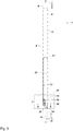
Fig. 3 is a view illustrating the entire structure of the power supply rail of the present invention; -
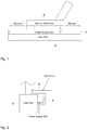
Fig. 4 is an enlarged cross-sectional view of a portion A inFig. 3 and a detailed view of a flexible flat cable; -
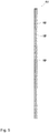
Fig. 5 is a cross-sectional view illustrating another configuration example of the flexible flat cable ofFig. 3 ; -
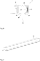
Fig. 6 is an enlarged cross-sectional view taken along line B-B ofFig. 3 ; -
Fig. 7 is an enlarged perspective view of the flexible flat cable and a guide plate constituting the power supply rail of the present invention; and -
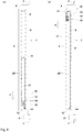
Fig. 8(a) is a diagram illustrating a state in which an actuator is in a forward position, andFig. 8(b) is a diagram illustrating a state in which the actuator is in a rear position, in the power supply rail of the present invention. - Hereinafter, embodiments for carrying out the present invention will be described with reference to the drawings.
- As illustrated in
Fig. 1 , apower supply rail 1 of the present embodiment is for supplying electric power from a power source of a vehicle such as an automobile to aslide seat 2 mounted on the vehicle. Thepower supply rail 1 is attached to and integrated with a side surface of theside rail 3 so that electric power can be continuously supplied when theslide seat 2 reciprocates forward and backward along theside rails 3. The present invention can be applied to any one of an electric type and a non-electric type (manual type) of theslide seat 2. - As illustrated in
Fig. 2 , aresin rail cover 4 is covered on thepower supply rail 1, and thepower supply rail 1 is protected so that foreign substance such as dust and sand inside the vehicle does not enter thepower supply rail 1. - As illustrated in
Fig. 3 , thepower supply rail 1 of the present embodiment is accommodated in analuminum mold 5 designed according to a moving distance of theslide seat 2 of a long slide type, and is entirely formed in an elongated shape. In addition,stopper caps mold 5 so that parts inside thepower supply rail 1 does not fall out, and thepower supply rail 1 can be attached to the side surface of theside rail 3 byfixing attachment holes cap 6 with screws. - The
case 8 is made of a metal such as aluminum, and is formed into an elongated rectangular tube shape so as to be accommodated in themold 5. Ahollow portion 9 extending in a longitudinal direction of thecase 8 is provided inside thecase 8, and amovable mechanism 10 described below reciprocates in thehollow portion 9 along a longitudinal direction of thehollow portion 9. - As illustrated in the enlarged view of
Fig. 4 , themovable mechanism 10 is configured by including components of a flexibleflat cable 11, afixed terminal 12, amovable terminal 13,bus bars actuator 16, and aguide plate 17. - The flexible
flat cable 11 is formed in a long flat shape to include a thin plate (a copper plate in the present embodiment) 18 made of a conductor and a heat-resistant insulation tape (a polyimide tape in the present embodiment) 19 covering an outer surface of thethin plate 18, and is accommodated in thehollow portion 9 within thecase 8. In the present embodiment, three flexibleflat cables 11 are superimposed. The reason for this is to increase an electric capacity so that thethin plate 18 does not melt by heat when large current flows through the flexibleflat cable 11. A larger number of flexibleflat cables 11 may be superimposed as long as they are within a range in which they can be bent and deformed, and only one flexibleflat cable 11 may be used as long as a sufficient electric capacity can be secured. Further, in order to alleviate heat due to large current, a flexibleflat cable 11 may be used in which thethin plates 18 are superimposed as illustrated inFig. 5 . - At one end of the flexible
flat cable 11,fixed terminals thin plates fixed terminals 12 are accommodated inside acap 6 provided at a tip of thecase 8, and bus bars (hereinafter, referred to as "fixed-side bus bars") 14, 14, and 14 made of copper plates are fixed by welding to thefixed terminals 12 respectively. The fixed-side bus bar 14 functions as a vehicle-side connector connected to wiring on the side of the vehicle. - On the other hand, at the other end of the flexible
flat cable 11,movable terminals thin plates movable terminals 13 are accommodated inside theactuator 16, and bus bars (hereinafter, referred to as "movable-side bus bars") 15, 15, and 15 made of copper plates are fixed by welding to the movable terminals respectively. The movable-side bus bar 15 functions as a seat-side connector connected to the wiring on the side of the seat. - The
actuator 16 is made of an insulator such as ABS resin and formed into a protruding cross-section shape having a width matching thehollow portion 9 as illustrated inFig. 6 , and theactuator 16 is provided withrecessed portions slits 20 of thecase 8. Thus, theactuator 16 accommodating the movable-side bus bars 15 slides along theslit 20 and is configured to reciprocate in the longitudinal direction of thecase 8. - By fixing the fixed-
side bus bars 14 and the movable-side bus bars 15 to both ends of the flexibleflat cable 11 in this manner, wiring work is simpler than that when connecting with lead wires, and an electrical resistance is small, enabling a large amount of current to flow. The method of fixing thefixed terminal 12 and the fixed-side bus bar 14 and fixing themovable terminal 13 and the movable-side bus bar 15 are not limited to welding, but other methods such as soldering, deposition, screwing, and caulking may be used. - The
guide plate 17 is made of a metal plate such as stainless steel and is formed into an elongated flat shape having the same width as that of the flexibleflat cable 11 as illustrated inFig. 7 , and is formed in a curved shape (arc-shaped) in which a cross-sectional shape thereof is convex toward the flexibleflat cable 11 by performing a process of drawing on the metal plate. As illustrated inFig. 6 , theguide plate 17 is accommodated in arail 22 laid on the inner surface of thecase 8, and a tip portion of theguide plate 17 is fixed to theactuator 16. Theguide plate 17 is configured to guide the movement of the flexibleflat cable 11 while pressing the flexibleflat cable 11 with a spring force in accordance with movement of theactuator 16. The material of theguide plate 17 may be a metal material or a resin material other than stainless steel, and a sectional shape of theguide plate 17 is not limited to a curved shape as long as it can press the flexibleflat cable 11 with a spring force. - The
power supply rail 1 configured as described above is provided with themovable mechanism 10 inside thecase 8, accommodated in themold 5, and attached to the side surface of theside rail 3 via thecaps actuator 16 accommodating the movable-side bus bars 15 protrudes to the outside of thecase 8, a wiring of a motor circuit of theslide seat 2 may be connected to the movable-side bus bars 15 and a wiring of the power supply circuit on the vehicle side may be connected to the fixed-side bus bars 14. Thus, the power supply circuit of the vehicle and the motor circuit of theslide seat 2 can be electrically connected via thepower supply rail 1. - That is, as illustrated in
Fig. 8(a) , when theactuator 16 of thepower supply rail 1 is in a front position of thecase 8, the fixed-side bus bars 14 and the movable-side bus bars 15 are connected via the flexibleflat cable 11. Therefore, Electric power can be supplied from the power supply circuit of the vehicle to the motor circuit of theslide seat 2. - When the
slide seat 2 illustrated inFig. 1 retreats along theside rail 3, as illustrated inFig. 8(b) , theactuator 16 accommodating the movable-side bus bars 15 is pushed toward a rear of thecase 8 and moves in a direction of an arrow R in the drawing in conjunction with theslide seat 2. At this time, in accordance with the movement of theactuator 16, the flexibleflat cable 11 slides within thehollow portion 9 in the direction of the arrow R while being pressed by the spring force of theguide plate 17. - On the other hand, when the
slide seat 2 illustrated inFig. 1 advances along theside rail 3, theactuator 16 accommodating the movable-side bus bars 15 is pushed toward a front of thecase 8 and moves in a direction of an arrow F direction in conjunction with theslide seat 2 as illustrated inFig. 8(a) . Here, the flexibleflat cable 11 connected to theactuator 16 slides within thehollow portion 9 in the direction of the arrow F. At this time, the flexibleflat cable 11 returns to an original position following a spring deformation of theguide plate 17. That is, since the flexibleflat cable 11 is pressed by theguide plate 17 so that the movement of the flexibleflat cable 11 by itself is restricted, the flexibleflat cable 11 does not bend or corrugate and deflect during the movement and is smoothly moved in a state in which the flexibleflat cable 11 always receives a constant tension applied thereto. - In this manner, when the
slide seat 2 advances or retreats, theactuator 16 slides along theslit 20 of thecase 8 in conjunction with the movement of theslide seat 2. Following the sliding of theactuator 16, theguide plate 17 and the flexibleflat cable 11 expand and contract integrally. Further, since there are no complicated wires or the like such as the wire harness in thehollow portion 9, it is possible to save troublesome work for distributing the wire harness. Further, there is no concern that, when theslide seat 2 advances and retreats, the wire or the like is caught in thehollow portion 9, thus hindering the movement or the wire or the like is twisted or pulled, thus causing a malfunction. Moreover, since the flexibleflat cable 11 is expanded and contracted following the spring deformation of theguide plate 17, theactuator 16 can move from a front end to a rear end along the longitudinal direction of thecase 8 as illustrated inFigs. 8(a) and 8(b) , thereby securing a long moving distance. - Therefore, according to the
power supply rail 1, the flexibleflat cable 11 guided by theguide plate 17 following the movement of theslide seat 2 smoothly expands and contracts. Thus, it is possible to continue to stably supply electric power from the power supply circuit of the vehicle to theslide seat 2. - In the present embodiment, one
movable mechanism 10 is provided in thehollow portion 9 to form one circuit, but the circuit configuration is not limited thereto. For example, a plurality ofmovable mechanisms 10 may be arranged in a height direction of thecase 8 by overlapping the flexibleflat cables 11 vertically or a plurality ofmovable mechanisms 10 may be arranged in a width direction of thecase 8 by arranging a plurality of the flexibleflat cables 11 with narrower widths in the left and right direction, thus forming a circuit configuration of two or more circuits. As a result, even when a fault occurs in themovable mechanism 10 of any one of the circuits, a fail-safe function for ensuring safety can be exerted by a normal operation of themovable mechanism 10 of the remaining circuit. - Further, in the present embodiment, electric power is supplied from the power supply circuit of the vehicle to the motor circuit of the
slide seat 2 via thepower supply rail 1, but the application is not limited thereto. For example, thepower supply rail 1 can be used for applications such as a USB charger, a heater device of a seat, a seat belt reminder (alarm device) mounted on a vehicle, power supply and signal transmission to a rear seat, and the like. -
- 1
- POWER SUPPLY RAIL
- 2
- SLIDE SEAT
- 3
- SIDE RAIL
- 4
- RAIL COVER
- 5
- MOLD
- 6
- CAP
- 7
- ATTACHMENT HOLES
- 8
- CASE
- 9
- HOLLOW PORTION
- 10
- MOVABLE MECHANISM
- 11
- FLEXIBLE FLAT CABLE
- 12
- FIXED TERMINAL
- 13
- MOVABLE TERMINAL
- 14
- FIXED-SIDE BUS BAR
- 15
- MOVABLE-SIDE BUS BAR
- 16
- ACTUATOR
- 17
- GUIDE PLATE
- 18
- THIN PLATE
- 19
- HEAT-RESISTANT INSULATION TAPE
- 20
- SLIT
- 21
- RECESSED PORTION
- 22
- RAIL
Claims (2)
- A power supply rail comprising:a long tubular case;a flexible flat cable accommodated in a hollow portion in the case;a fixed terminal provided at one end of the flexible flat cable and fixed to the case;a movable terminal provided at the other end of the flexible flat cable and movable in a longitudinal direction of the case;an actuator that accommodates the movable terminal and moves along a slit of the case; anda guide plate that guides the movement of the flexible flat cable while pressing the flexible flat cable in accordance with the movement of the actuator.
- The power supply rail according to claim 1, wherein a cross-sectional shape of the guide plate is formed in a curved shape that protrudes toward the flexible flat cable.
Applications Claiming Priority (1)
| Application Number | Priority Date | Filing Date | Title |
|---|---|---|---|
| JP2017120973A JP6353960B2 (en) | 2016-10-20 | 2017-06-21 | Feed rail |
Publications (2)
| Publication Number | Publication Date |
|---|---|
| EP3418109A1 true EP3418109A1 (en) | 2018-12-26 |
| EP3418109B1 EP3418109B1 (en) | 2020-11-25 |
Family
ID=62748787
Family Applications (1)
| Application Number | Title | Priority Date | Filing Date |
|---|---|---|---|
| EP18178973.6A Active EP3418109B1 (en) | 2017-06-21 | 2018-06-21 | Power supply rail |
Country Status (4)
| Country | Link |
|---|---|
| US (1) | US10618432B2 (en) |
| EP (1) | EP3418109B1 (en) |
| KR (1) | KR102090327B1 (en) |
| CN (1) | CN109094431B (en) |
Cited By (1)
| Publication number | Priority date | Publication date | Assignee | Title |
|---|---|---|---|---|
| EP3907103A4 (en) * | 2019-01-02 | 2022-10-05 | Yanfeng Adient Seating Co. Ltd. | MECHANISM FOR QUICK ASSEMBLY AND PROTECTION OF A CABLE HARNESS IN A SLIDING RAIL |
Families Citing this family (6)
| Publication number | Priority date | Publication date | Assignee | Title |
|---|---|---|---|---|
| JP2020078169A (en) * | 2018-11-07 | 2020-05-21 | 矢崎総業株式会社 | Cabling structure |
| KR20220078989A (en) | 2020-12-04 | 2022-06-13 | 정웅진 | microplastic reduction washing machine filter using microbubble |
| CN112864943B (en) * | 2021-01-14 | 2022-06-17 | 中建七局安装工程有限公司 | Built on stilts interim regulation support frame is laid to cable of building site operation |
| JP7608238B2 (en) * | 2021-03-29 | 2025-01-06 | 古河電気工業株式会社 | Wiring structure and rail unit |
| CN119173416A (en) * | 2022-05-25 | 2024-12-20 | 提爱思科技股份有限公司 | Power supply rail and vehicle seat |
| KR20260033220A (en) * | 2024-09-02 | 2026-03-10 | 대원산업 주식회사 | Flexible flat cable apparatus and seat sliding apparatus for vehicle having the same |
Citations (4)
| Publication number | Priority date | Publication date | Assignee | Title |
|---|---|---|---|---|
| JPH0956046A (en) * | 1995-08-10 | 1997-02-25 | Furukawa Electric Co Ltd:The | Reciprocating electrical connection device |
| JPH10112922A (en) * | 1996-10-02 | 1998-04-28 | Yazaki Corp | Harness storage structure |
| JP2005059745A (en) | 2003-08-13 | 2005-03-10 | Yazaki Corp | Power supply device for slide sheet |
| FR2874134A1 (en) * | 2004-08-06 | 2006-02-10 | Yazaki Corp | POWER SUPPLY DEVICE FOR SLIDING STRUCTURE |
Family Cites Families (7)
| Publication number | Priority date | Publication date | Assignee | Title |
|---|---|---|---|---|
| JP2007116782A (en) * | 2005-10-18 | 2007-05-10 | Yazaki Corp | Routing device |
| JP5179943B2 (en) * | 2008-05-09 | 2013-04-10 | 矢崎総業株式会社 | Electric wire cabling device and method of manufacturing electric cabling device |
| KR101539311B1 (en) * | 2009-03-25 | 2015-07-24 | 다이덴 가부시키가이샤 | Elongated structure for movable sections |
| JP5781878B2 (en) * | 2011-09-26 | 2015-09-24 | 矢崎総業株式会社 | Signal transmitter / receiver |
| JP5885594B2 (en) * | 2012-06-04 | 2016-03-15 | 矢崎総業株式会社 | Flat cable connector |
| JP2016131423A (en) * | 2015-01-13 | 2016-07-21 | 株式会社オートネットワーク技術研究所 | Wire protection member, wire harness with wire protection member, and slide wiring device |
| JP6640255B2 (en) * | 2018-02-20 | 2020-02-05 | 矢崎総業株式会社 | Bending control member and power supply device |
-
2018
- 2018-06-19 KR KR1020180070199A patent/KR102090327B1/en active Active
- 2018-06-20 CN CN201810638295.3A patent/CN109094431B/en active Active
- 2018-06-21 US US16/014,135 patent/US10618432B2/en active Active
- 2018-06-21 EP EP18178973.6A patent/EP3418109B1/en active Active
Patent Citations (4)
| Publication number | Priority date | Publication date | Assignee | Title |
|---|---|---|---|---|
| JPH0956046A (en) * | 1995-08-10 | 1997-02-25 | Furukawa Electric Co Ltd:The | Reciprocating electrical connection device |
| JPH10112922A (en) * | 1996-10-02 | 1998-04-28 | Yazaki Corp | Harness storage structure |
| JP2005059745A (en) | 2003-08-13 | 2005-03-10 | Yazaki Corp | Power supply device for slide sheet |
| FR2874134A1 (en) * | 2004-08-06 | 2006-02-10 | Yazaki Corp | POWER SUPPLY DEVICE FOR SLIDING STRUCTURE |
Cited By (1)
| Publication number | Priority date | Publication date | Assignee | Title |
|---|---|---|---|---|
| EP3907103A4 (en) * | 2019-01-02 | 2022-10-05 | Yanfeng Adient Seating Co. Ltd. | MECHANISM FOR QUICK ASSEMBLY AND PROTECTION OF A CABLE HARNESS IN A SLIDING RAIL |
Also Published As
| Publication number | Publication date |
|---|---|
| US20180370389A1 (en) | 2018-12-27 |
| CN109094431A (en) | 2018-12-28 |
| KR102090327B1 (en) | 2020-03-17 |
| CN109094431B (en) | 2021-04-16 |
| US10618432B2 (en) | 2020-04-14 |
| KR20180138537A (en) | 2018-12-31 |
| EP3418109B1 (en) | 2020-11-25 |
Similar Documents
| Publication | Publication Date | Title |
|---|---|---|
| EP3418109B1 (en) | Power supply rail | |
| JP6455908B1 (en) | Feed rail | |
| JP6353960B2 (en) | Feed rail | |
| JP2016043902A (en) | Feed rail | |
| JP6258090B2 (en) | Feed rail | |
| US8398115B2 (en) | Vehicle steering wheel | |
| EP2922159A1 (en) | Wire harness | |
| CN111152693A (en) | Wiring structure | |
| DE112018005474B4 (en) | Cable harness routing device | |
| US10596983B2 (en) | Wire harness | |
| JP6455907B1 (en) | Feed rail | |
| HK1261691A1 (en) | Power supply rail | |
| JP7385982B1 (en) | power supply rail | |
| CN109074908B (en) | Wire harness | |
| US20240116467A1 (en) | Electrical connection box | |
| JP6756670B2 (en) | Cable extra length absorption structure and bus bar module | |
| US12525734B2 (en) | Connector | |
| HK1261691B (en) | Power supply rail | |
| DE102017221563B4 (en) | Method for manufacturing a wiring harness | |
| US12071081B2 (en) | Wire harness routing device | |
| JP5750290B2 (en) | Wire harness forming jig and method of manufacturing wire harness | |
| WO2021117458A1 (en) | Exterior body, wire harness, wire harness routing device, manufacturing method for exterior body, and manufacturing method for wire harness | |
| JP2023118241A (en) | wire harness | |
| US11239621B2 (en) | Double-row plug for a ribbon or foil cable, method for the production thereof, and apparatus for the transmission of current | |
| CN119968746A (en) | Wiring harness routing device |
Legal Events
| Date | Code | Title | Description |
|---|---|---|---|
| PUAI | Public reference made under article 153(3) epc to a published international application that has entered the european phase |
Free format text: ORIGINAL CODE: 0009012 |
|
| STAA | Information on the status of an ep patent application or granted ep patent |
Free format text: STATUS: THE APPLICATION HAS BEEN PUBLISHED |
|
| AK | Designated contracting states |
Kind code of ref document: A1 Designated state(s): AL AT BE BG CH CY CZ DE DK EE ES FI FR GB GR HR HU IE IS IT LI LT LU LV MC MK MT NL NO PL PT RO RS SE SI SK SM TR |
|
| AX | Request for extension of the european patent |
Extension state: BA ME |
|
| RAP1 | Party data changed (applicant data changed or rights of an application transferred) |
Owner name: MIK ELECTRONIC CORPORATION |
|
| STAA | Information on the status of an ep patent application or granted ep patent |
Free format text: STATUS: REQUEST FOR EXAMINATION WAS MADE |
|
| 17P | Request for examination filed |
Effective date: 20190531 |
|
| RBV | Designated contracting states (corrected) |
Designated state(s): AL AT BE BG CH CY CZ DE DK EE ES FI FR GB GR HR HU IE IS IT LI LT LU LV MC MK MT NL NO PL PT RO RS SE SI SK SM TR |
|
| GRAP | Despatch of communication of intention to grant a patent |
Free format text: ORIGINAL CODE: EPIDOSNIGR1 |
|
| STAA | Information on the status of an ep patent application or granted ep patent |
Free format text: STATUS: GRANT OF PATENT IS INTENDED |
|
| RIC1 | Information provided on ipc code assigned before grant |
Ipc: B60N 2/02 20060101AFI20200528BHEP |
|
| INTG | Intention to grant announced |
Effective date: 20200618 |
|
| GRAS | Grant fee paid |
Free format text: ORIGINAL CODE: EPIDOSNIGR3 |
|
| GRAA | (expected) grant |
Free format text: ORIGINAL CODE: 0009210 |
|
| STAA | Information on the status of an ep patent application or granted ep patent |
Free format text: STATUS: THE PATENT HAS BEEN GRANTED |
|
| AK | Designated contracting states |
Kind code of ref document: B1 Designated state(s): AL AT BE BG CH CY CZ DE DK EE ES FI FR GB GR HR HU IE IS IT LI LT LU LV MC MK MT NL NO PL PT RO RS SE SI SK SM TR |
|
| REG | Reference to a national code |
Ref country code: GB Ref legal event code: FG4D |
|
| REG | Reference to a national code |
Ref country code: CH Ref legal event code: EP |
|
| REG | Reference to a national code |
Ref country code: AT Ref legal event code: REF Ref document number: 1337913 Country of ref document: AT Kind code of ref document: T Effective date: 20201215 |
|
| REG | Reference to a national code |
Ref country code: DE Ref legal event code: R096 Ref document number: 602018010025 Country of ref document: DE |
|
| REG | Reference to a national code |
Ref country code: IE Ref legal event code: FG4D |
|
| REG | Reference to a national code |
Ref country code: AT Ref legal event code: MK05 Ref document number: 1337913 Country of ref document: AT Kind code of ref document: T Effective date: 20201125 |
|
| REG | Reference to a national code |
Ref country code: NL Ref legal event code: MP Effective date: 20201125 |
|
| PG25 | Lapsed in a contracting state [announced via postgrant information from national office to epo] |
Ref country code: FI Free format text: LAPSE BECAUSE OF FAILURE TO SUBMIT A TRANSLATION OF THE DESCRIPTION OR TO PAY THE FEE WITHIN THE PRESCRIBED TIME-LIMIT Effective date: 20201125 Ref country code: PT Free format text: LAPSE BECAUSE OF FAILURE TO SUBMIT A TRANSLATION OF THE DESCRIPTION OR TO PAY THE FEE WITHIN THE PRESCRIBED TIME-LIMIT Effective date: 20210325 Ref country code: RS Free format text: LAPSE BECAUSE OF FAILURE TO SUBMIT A TRANSLATION OF THE DESCRIPTION OR TO PAY THE FEE WITHIN THE PRESCRIBED TIME-LIMIT Effective date: 20201125 Ref country code: NO Free format text: LAPSE BECAUSE OF FAILURE TO SUBMIT A TRANSLATION OF THE DESCRIPTION OR TO PAY THE FEE WITHIN THE PRESCRIBED TIME-LIMIT Effective date: 20210225 Ref country code: GR Free format text: LAPSE BECAUSE OF FAILURE TO SUBMIT A TRANSLATION OF THE DESCRIPTION OR TO PAY THE FEE WITHIN THE PRESCRIBED TIME-LIMIT Effective date: 20210226 |
|
| PG25 | Lapsed in a contracting state [announced via postgrant information from national office to epo] |
Ref country code: LV Free format text: LAPSE BECAUSE OF FAILURE TO SUBMIT A TRANSLATION OF THE DESCRIPTION OR TO PAY THE FEE WITHIN THE PRESCRIBED TIME-LIMIT Effective date: 20201125 Ref country code: IS Free format text: LAPSE BECAUSE OF FAILURE TO SUBMIT A TRANSLATION OF THE DESCRIPTION OR TO PAY THE FEE WITHIN THE PRESCRIBED TIME-LIMIT Effective date: 20210325 Ref country code: PL Free format text: LAPSE BECAUSE OF FAILURE TO SUBMIT A TRANSLATION OF THE DESCRIPTION OR TO PAY THE FEE WITHIN THE PRESCRIBED TIME-LIMIT Effective date: 20201125 Ref country code: SE Free format text: LAPSE BECAUSE OF FAILURE TO SUBMIT A TRANSLATION OF THE DESCRIPTION OR TO PAY THE FEE WITHIN THE PRESCRIBED TIME-LIMIT Effective date: 20201125 Ref country code: BG Free format text: LAPSE BECAUSE OF FAILURE TO SUBMIT A TRANSLATION OF THE DESCRIPTION OR TO PAY THE FEE WITHIN THE PRESCRIBED TIME-LIMIT Effective date: 20210225 Ref country code: AT Free format text: LAPSE BECAUSE OF FAILURE TO SUBMIT A TRANSLATION OF THE DESCRIPTION OR TO PAY THE FEE WITHIN THE PRESCRIBED TIME-LIMIT Effective date: 20201125 |
|
| REG | Reference to a national code |
Ref country code: LT Ref legal event code: MG9D |
|
| PG25 | Lapsed in a contracting state [announced via postgrant information from national office to epo] |
Ref country code: HR Free format text: LAPSE BECAUSE OF FAILURE TO SUBMIT A TRANSLATION OF THE DESCRIPTION OR TO PAY THE FEE WITHIN THE PRESCRIBED TIME-LIMIT Effective date: 20201125 |
|
| PG25 | Lapsed in a contracting state [announced via postgrant information from national office to epo] |
Ref country code: LT Free format text: LAPSE BECAUSE OF FAILURE TO SUBMIT A TRANSLATION OF THE DESCRIPTION OR TO PAY THE FEE WITHIN THE PRESCRIBED TIME-LIMIT Effective date: 20201125 Ref country code: SK Free format text: LAPSE BECAUSE OF FAILURE TO SUBMIT A TRANSLATION OF THE DESCRIPTION OR TO PAY THE FEE WITHIN THE PRESCRIBED TIME-LIMIT Effective date: 20201125 Ref country code: RO Free format text: LAPSE BECAUSE OF FAILURE TO SUBMIT A TRANSLATION OF THE DESCRIPTION OR TO PAY THE FEE WITHIN THE PRESCRIBED TIME-LIMIT Effective date: 20201125 Ref country code: SM Free format text: LAPSE BECAUSE OF FAILURE TO SUBMIT A TRANSLATION OF THE DESCRIPTION OR TO PAY THE FEE WITHIN THE PRESCRIBED TIME-LIMIT Effective date: 20201125 Ref country code: CZ Free format text: LAPSE BECAUSE OF FAILURE TO SUBMIT A TRANSLATION OF THE DESCRIPTION OR TO PAY THE FEE WITHIN THE PRESCRIBED TIME-LIMIT Effective date: 20201125 Ref country code: EE Free format text: LAPSE BECAUSE OF FAILURE TO SUBMIT A TRANSLATION OF THE DESCRIPTION OR TO PAY THE FEE WITHIN THE PRESCRIBED TIME-LIMIT Effective date: 20201125 |
|
| REG | Reference to a national code |
Ref country code: DE Ref legal event code: R097 Ref document number: 602018010025 Country of ref document: DE |
|
| PG25 | Lapsed in a contracting state [announced via postgrant information from national office to epo] |
Ref country code: DK Free format text: LAPSE BECAUSE OF FAILURE TO SUBMIT A TRANSLATION OF THE DESCRIPTION OR TO PAY THE FEE WITHIN THE PRESCRIBED TIME-LIMIT Effective date: 20201125 |
|
| PLBE | No opposition filed within time limit |
Free format text: ORIGINAL CODE: 0009261 |
|
| STAA | Information on the status of an ep patent application or granted ep patent |
Free format text: STATUS: NO OPPOSITION FILED WITHIN TIME LIMIT |
|
| PG25 | Lapsed in a contracting state [announced via postgrant information from national office to epo] |
Ref country code: NL Free format text: LAPSE BECAUSE OF FAILURE TO SUBMIT A TRANSLATION OF THE DESCRIPTION OR TO PAY THE FEE WITHIN THE PRESCRIBED TIME-LIMIT Effective date: 20201125 Ref country code: AL Free format text: LAPSE BECAUSE OF FAILURE TO SUBMIT A TRANSLATION OF THE DESCRIPTION OR TO PAY THE FEE WITHIN THE PRESCRIBED TIME-LIMIT Effective date: 20201125 |
|
| 26N | No opposition filed |
Effective date: 20210826 |
|
| PG25 | Lapsed in a contracting state [announced via postgrant information from national office to epo] |
Ref country code: SI Free format text: LAPSE BECAUSE OF FAILURE TO SUBMIT A TRANSLATION OF THE DESCRIPTION OR TO PAY THE FEE WITHIN THE PRESCRIBED TIME-LIMIT Effective date: 20201125 |
|
| PG25 | Lapsed in a contracting state [announced via postgrant information from national office to epo] |
Ref country code: ES Free format text: LAPSE BECAUSE OF FAILURE TO SUBMIT A TRANSLATION OF THE DESCRIPTION OR TO PAY THE FEE WITHIN THE PRESCRIBED TIME-LIMIT Effective date: 20201125 Ref country code: MC Free format text: LAPSE BECAUSE OF FAILURE TO SUBMIT A TRANSLATION OF THE DESCRIPTION OR TO PAY THE FEE WITHIN THE PRESCRIBED TIME-LIMIT Effective date: 20201125 |
|
| REG | Reference to a national code |
Ref country code: CH Ref legal event code: PL |
|
| REG | Reference to a national code |
Ref country code: BE Ref legal event code: MM Effective date: 20210630 |
|
| PG25 | Lapsed in a contracting state [announced via postgrant information from national office to epo] |
Ref country code: LU Free format text: LAPSE BECAUSE OF NON-PAYMENT OF DUE FEES Effective date: 20210621 |
|
| PG25 | Lapsed in a contracting state [announced via postgrant information from national office to epo] |
Ref country code: LI Free format text: LAPSE BECAUSE OF NON-PAYMENT OF DUE FEES Effective date: 20210630 Ref country code: IE Free format text: LAPSE BECAUSE OF NON-PAYMENT OF DUE FEES Effective date: 20210621 Ref country code: CH Free format text: LAPSE BECAUSE OF NON-PAYMENT OF DUE FEES Effective date: 20210630 |
|
| PG25 | Lapsed in a contracting state [announced via postgrant information from national office to epo] |
Ref country code: IS Free format text: LAPSE BECAUSE OF FAILURE TO SUBMIT A TRANSLATION OF THE DESCRIPTION OR TO PAY THE FEE WITHIN THE PRESCRIBED TIME-LIMIT Effective date: 20210325 |
|
| PG25 | Lapsed in a contracting state [announced via postgrant information from national office to epo] |
Ref country code: BE Free format text: LAPSE BECAUSE OF NON-PAYMENT OF DUE FEES Effective date: 20210630 |
|
| GBPC | Gb: european patent ceased through non-payment of renewal fee |
Effective date: 20220621 |
|
| PG25 | Lapsed in a contracting state [announced via postgrant information from national office to epo] |
Ref country code: GB Free format text: LAPSE BECAUSE OF NON-PAYMENT OF DUE FEES Effective date: 20220621 |
|
| PG25 | Lapsed in a contracting state [announced via postgrant information from national office to epo] |
Ref country code: CY Free format text: LAPSE BECAUSE OF FAILURE TO SUBMIT A TRANSLATION OF THE DESCRIPTION OR TO PAY THE FEE WITHIN THE PRESCRIBED TIME-LIMIT Effective date: 20201125 |
|
| PG25 | Lapsed in a contracting state [announced via postgrant information from national office to epo] |
Ref country code: HU Free format text: LAPSE BECAUSE OF FAILURE TO SUBMIT A TRANSLATION OF THE DESCRIPTION OR TO PAY THE FEE WITHIN THE PRESCRIBED TIME-LIMIT; INVALID AB INITIO Effective date: 20180621 |
|
| PG25 | Lapsed in a contracting state [announced via postgrant information from national office to epo] |
Ref country code: MK Free format text: LAPSE BECAUSE OF FAILURE TO SUBMIT A TRANSLATION OF THE DESCRIPTION OR TO PAY THE FEE WITHIN THE PRESCRIBED TIME-LIMIT Effective date: 20201125 |
|
| PG25 | Lapsed in a contracting state [announced via postgrant information from national office to epo] |
Ref country code: TR Free format text: LAPSE BECAUSE OF FAILURE TO SUBMIT A TRANSLATION OF THE DESCRIPTION OR TO PAY THE FEE WITHIN THE PRESCRIBED TIME-LIMIT Effective date: 20201125 |
|
| PG25 | Lapsed in a contracting state [announced via postgrant information from national office to epo] |
Ref country code: MT Free format text: LAPSE BECAUSE OF FAILURE TO SUBMIT A TRANSLATION OF THE DESCRIPTION OR TO PAY THE FEE WITHIN THE PRESCRIBED TIME-LIMIT Effective date: 20201125 |
|
| PGFP | Annual fee paid to national office [announced via postgrant information from national office to epo] |
Ref country code: FR Payment date: 20250624 Year of fee payment: 8 |
|
| PGFP | Annual fee paid to national office [announced via postgrant information from national office to epo] |
Ref country code: DE Payment date: 20250626 Year of fee payment: 8 |
|
| PGFP | Annual fee paid to national office [announced via postgrant information from national office to epo] |
Ref country code: IT Payment date: 20250630 Year of fee payment: 8 |