EP3418093A1 - Electric kart and battery - Google Patents
Electric kart and battery Download PDFInfo
- Publication number
- EP3418093A1 EP3418093A1 EP18179287.0A EP18179287A EP3418093A1 EP 3418093 A1 EP3418093 A1 EP 3418093A1 EP 18179287 A EP18179287 A EP 18179287A EP 3418093 A1 EP3418093 A1 EP 3418093A1
- Authority
- EP
- European Patent Office
- Prior art keywords
- battery
- battery cells
- sleeve
- electric
- rack
- Prior art date
- Legal status (The legal status is an assumption and is not a legal conclusion. Google has not performed a legal analysis and makes no representation as to the accuracy of the status listed.)
- Granted
Links
Images








Classifications
-
- B—PERFORMING OPERATIONS; TRANSPORTING
- B60—VEHICLES IN GENERAL
- B60K—ARRANGEMENT OR MOUNTING OF PROPULSION UNITS OR OF TRANSMISSIONS IN VEHICLES; ARRANGEMENT OR MOUNTING OF PLURAL DIVERSE PRIME-MOVERS IN VEHICLES; AUXILIARY DRIVES FOR VEHICLES; INSTRUMENTATION OR DASHBOARDS FOR VEHICLES; ARRANGEMENTS IN CONNECTION WITH COOLING, AIR INTAKE, GAS EXHAUST OR FUEL SUPPLY OF PROPULSION UNITS IN VEHICLES
- B60K1/00—Arrangement or mounting of electrical propulsion units
- B60K1/04—Arrangement or mounting of electrical propulsion units of the electric storage means for propulsion
-
- B—PERFORMING OPERATIONS; TRANSPORTING
- B60—VEHICLES IN GENERAL
- B60L—PROPULSION OF ELECTRICALLY-PROPELLED VEHICLES; SUPPLYING ELECTRIC POWER FOR AUXILIARY EQUIPMENT OF ELECTRICALLY-PROPELLED VEHICLES; ELECTRODYNAMIC BRAKE SYSTEMS FOR VEHICLES IN GENERAL; MAGNETIC SUSPENSION OR LEVITATION FOR VEHICLES; MONITORING OPERATING VARIABLES OF ELECTRICALLY-PROPELLED VEHICLES; ELECTRIC SAFETY DEVICES FOR ELECTRICALLY-PROPELLED VEHICLES
- B60L3/00—Electric devices on electrically-propelled vehicles for safety purposes; Monitoring operating variables, e.g. speed, deceleration or energy consumption
- B60L3/0023—Detecting, eliminating, remedying or compensating for drive train abnormalities, e.g. failures within the drive train
- B60L3/0046—Detecting, eliminating, remedying or compensating for drive train abnormalities, e.g. failures within the drive train relating to electric energy storage systems, e.g. batteries or capacitors
-
- B—PERFORMING OPERATIONS; TRANSPORTING
- B60—VEHICLES IN GENERAL
- B60L—PROPULSION OF ELECTRICALLY-PROPELLED VEHICLES; SUPPLYING ELECTRIC POWER FOR AUXILIARY EQUIPMENT OF ELECTRICALLY-PROPELLED VEHICLES; ELECTRODYNAMIC BRAKE SYSTEMS FOR VEHICLES IN GENERAL; MAGNETIC SUSPENSION OR LEVITATION FOR VEHICLES; MONITORING OPERATING VARIABLES OF ELECTRICALLY-PROPELLED VEHICLES; ELECTRIC SAFETY DEVICES FOR ELECTRICALLY-PROPELLED VEHICLES
- B60L50/00—Electric propulsion with power supplied within the vehicle
- B60L50/50—Electric propulsion with power supplied within the vehicle using propulsion power supplied by batteries or fuel cells
- B60L50/52—Electric propulsion with power supplied within the vehicle using propulsion power supplied by batteries or fuel cells characterised by DC-motors
-
- B—PERFORMING OPERATIONS; TRANSPORTING
- B60—VEHICLES IN GENERAL
- B60L—PROPULSION OF ELECTRICALLY-PROPELLED VEHICLES; SUPPLYING ELECTRIC POWER FOR AUXILIARY EQUIPMENT OF ELECTRICALLY-PROPELLED VEHICLES; ELECTRODYNAMIC BRAKE SYSTEMS FOR VEHICLES IN GENERAL; MAGNETIC SUSPENSION OR LEVITATION FOR VEHICLES; MONITORING OPERATING VARIABLES OF ELECTRICALLY-PROPELLED VEHICLES; ELECTRIC SAFETY DEVICES FOR ELECTRICALLY-PROPELLED VEHICLES
- B60L50/00—Electric propulsion with power supplied within the vehicle
- B60L50/50—Electric propulsion with power supplied within the vehicle using propulsion power supplied by batteries or fuel cells
- B60L50/60—Electric propulsion with power supplied within the vehicle using propulsion power supplied by batteries or fuel cells using power supplied by batteries
- B60L50/64—Constructional details of batteries specially adapted for electric vehicles
-
- B—PERFORMING OPERATIONS; TRANSPORTING
- B60—VEHICLES IN GENERAL
- B60L—PROPULSION OF ELECTRICALLY-PROPELLED VEHICLES; SUPPLYING ELECTRIC POWER FOR AUXILIARY EQUIPMENT OF ELECTRICALLY-PROPELLED VEHICLES; ELECTRODYNAMIC BRAKE SYSTEMS FOR VEHICLES IN GENERAL; MAGNETIC SUSPENSION OR LEVITATION FOR VEHICLES; MONITORING OPERATING VARIABLES OF ELECTRICALLY-PROPELLED VEHICLES; ELECTRIC SAFETY DEVICES FOR ELECTRICALLY-PROPELLED VEHICLES
- B60L50/00—Electric propulsion with power supplied within the vehicle
- B60L50/50—Electric propulsion with power supplied within the vehicle using propulsion power supplied by batteries or fuel cells
- B60L50/60—Electric propulsion with power supplied within the vehicle using propulsion power supplied by batteries or fuel cells using power supplied by batteries
- B60L50/66—Arrangements of batteries
-
- B—PERFORMING OPERATIONS; TRANSPORTING
- B60—VEHICLES IN GENERAL
- B60L—PROPULSION OF ELECTRICALLY-PROPELLED VEHICLES; SUPPLYING ELECTRIC POWER FOR AUXILIARY EQUIPMENT OF ELECTRICALLY-PROPELLED VEHICLES; ELECTRODYNAMIC BRAKE SYSTEMS FOR VEHICLES IN GENERAL; MAGNETIC SUSPENSION OR LEVITATION FOR VEHICLES; MONITORING OPERATING VARIABLES OF ELECTRICALLY-PROPELLED VEHICLES; ELECTRIC SAFETY DEVICES FOR ELECTRICALLY-PROPELLED VEHICLES
- B60L53/00—Methods of charging batteries, specially adapted for electric vehicles; Charging stations or on-board charging equipment therefor; Exchange of energy storage elements in electric vehicles
- B60L53/80—Exchanging energy storage elements, e.g. removable batteries
-
- B—PERFORMING OPERATIONS; TRANSPORTING
- B60—VEHICLES IN GENERAL
- B60L—PROPULSION OF ELECTRICALLY-PROPELLED VEHICLES; SUPPLYING ELECTRIC POWER FOR AUXILIARY EQUIPMENT OF ELECTRICALLY-PROPELLED VEHICLES; ELECTRODYNAMIC BRAKE SYSTEMS FOR VEHICLES IN GENERAL; MAGNETIC SUSPENSION OR LEVITATION FOR VEHICLES; MONITORING OPERATING VARIABLES OF ELECTRICALLY-PROPELLED VEHICLES; ELECTRIC SAFETY DEVICES FOR ELECTRICALLY-PROPELLED VEHICLES
- B60L58/00—Methods or circuit arrangements for monitoring or controlling batteries or fuel cells, specially adapted for electric vehicles
- B60L58/10—Methods or circuit arrangements for monitoring or controlling batteries or fuel cells, specially adapted for electric vehicles for monitoring or controlling batteries
- B60L58/18—Methods or circuit arrangements for monitoring or controlling batteries or fuel cells, specially adapted for electric vehicles for monitoring or controlling batteries of two or more battery modules
- B60L58/19—Switching between serial connection and parallel connection of battery modules
-
- B—PERFORMING OPERATIONS; TRANSPORTING
- B60—VEHICLES IN GENERAL
- B60L—PROPULSION OF ELECTRICALLY-PROPELLED VEHICLES; SUPPLYING ELECTRIC POWER FOR AUXILIARY EQUIPMENT OF ELECTRICALLY-PROPELLED VEHICLES; ELECTRODYNAMIC BRAKE SYSTEMS FOR VEHICLES IN GENERAL; MAGNETIC SUSPENSION OR LEVITATION FOR VEHICLES; MONITORING OPERATING VARIABLES OF ELECTRICALLY-PROPELLED VEHICLES; ELECTRIC SAFETY DEVICES FOR ELECTRICALLY-PROPELLED VEHICLES
- B60L58/00—Methods or circuit arrangements for monitoring or controlling batteries or fuel cells, specially adapted for electric vehicles
- B60L58/10—Methods or circuit arrangements for monitoring or controlling batteries or fuel cells, specially adapted for electric vehicles for monitoring or controlling batteries
- B60L58/24—Methods or circuit arrangements for monitoring or controlling batteries or fuel cells, specially adapted for electric vehicles for monitoring or controlling batteries for controlling the temperature of batteries
- B60L58/26—Methods or circuit arrangements for monitoring or controlling batteries or fuel cells, specially adapted for electric vehicles for monitoring or controlling batteries for controlling the temperature of batteries by cooling
-
- H—ELECTRICITY
- H01—ELECTRIC ELEMENTS
- H01M—PROCESSES OR MEANS, e.g. BATTERIES, FOR THE DIRECT CONVERSION OF CHEMICAL ENERGY INTO ELECTRICAL ENERGY
- H01M10/00—Secondary cells; Manufacture thereof
- H01M10/42—Methods or arrangements for servicing or maintenance of secondary cells or secondary half-cells
- H01M10/425—Structural combination with electronic components, e.g. electronic circuits integrated to the outside of the casing
-
- H—ELECTRICITY
- H01—ELECTRIC ELEMENTS
- H01M—PROCESSES OR MEANS, e.g. BATTERIES, FOR THE DIRECT CONVERSION OF CHEMICAL ENERGY INTO ELECTRICAL ENERGY
- H01M10/00—Secondary cells; Manufacture thereof
- H01M10/60—Heating or cooling; Temperature control
- H01M10/61—Types of temperature control
- H01M10/613—Cooling or keeping cold
-
- H—ELECTRICITY
- H01—ELECTRIC ELEMENTS
- H01M—PROCESSES OR MEANS, e.g. BATTERIES, FOR THE DIRECT CONVERSION OF CHEMICAL ENERGY INTO ELECTRICAL ENERGY
- H01M10/00—Secondary cells; Manufacture thereof
- H01M10/60—Heating or cooling; Temperature control
- H01M10/62—Heating or cooling; Temperature control specially adapted for specific applications
- H01M10/625—Vehicles
-
- H—ELECTRICITY
- H01—ELECTRIC ELEMENTS
- H01M—PROCESSES OR MEANS, e.g. BATTERIES, FOR THE DIRECT CONVERSION OF CHEMICAL ENERGY INTO ELECTRICAL ENERGY
- H01M10/00—Secondary cells; Manufacture thereof
- H01M10/60—Heating or cooling; Temperature control
- H01M10/65—Means for temperature control structurally associated with the cells
- H01M10/656—Means for temperature control structurally associated with the cells characterised by the type of heat-exchange fluid
- H01M10/6561—Gases
- H01M10/6562—Gases with free flow by convection only
-
- H—ELECTRICITY
- H01—ELECTRIC ELEMENTS
- H01M—PROCESSES OR MEANS, e.g. BATTERIES, FOR THE DIRECT CONVERSION OF CHEMICAL ENERGY INTO ELECTRICAL ENERGY
- H01M50/00—Constructional details or processes of manufacture of the non-active parts of electrochemical cells other than fuel cells, e.g. hybrid cells
- H01M50/20—Mountings; Secondary casings or frames; Racks, modules or packs; Suspension devices; Shock absorbers; Transport or carrying devices; Holders
- H01M50/249—Mountings; Secondary casings or frames; Racks, modules or packs; Suspension devices; Shock absorbers; Transport or carrying devices; Holders specially adapted for aircraft or vehicles, e.g. cars or trains
-
- H—ELECTRICITY
- H02—GENERATION; CONVERSION OR DISTRIBUTION OF ELECTRIC POWER
- H02J—ELECTRIC POWER NETWORKS; CIRCUIT ARRANGEMENTS OR SYSTEMS FOR SUPPLYING OR DISTRIBUTING ELECTRIC POWER; SYSTEMS FOR STORING ELECTRIC ENERGY
- H02J7/00—Circuit arrangements for charging or discharging batteries or for supplying loads from batteries
- H02J7/60—Circuit arrangements for charging or discharging batteries or for supplying loads from batteries including safety or protection arrangements
- H02J7/65—Circuit arrangements for charging or discharging batteries or for supplying loads from batteries including safety or protection arrangements against overtemperature
-
- B—PERFORMING OPERATIONS; TRANSPORTING
- B60—VEHICLES IN GENERAL
- B60G—VEHICLE SUSPENSION ARRANGEMENTS
- B60G2300/00—Indexing codes relating to the type of vehicle
- B60G2300/26—Carts
-
- B—PERFORMING OPERATIONS; TRANSPORTING
- B60—VEHICLES IN GENERAL
- B60K—ARRANGEMENT OR MOUNTING OF PROPULSION UNITS OR OF TRANSMISSIONS IN VEHICLES; ARRANGEMENT OR MOUNTING OF PLURAL DIVERSE PRIME-MOVERS IN VEHICLES; AUXILIARY DRIVES FOR VEHICLES; INSTRUMENTATION OR DASHBOARDS FOR VEHICLES; ARRANGEMENTS IN CONNECTION WITH COOLING, AIR INTAKE, GAS EXHAUST OR FUEL SUPPLY OF PROPULSION UNITS IN VEHICLES
- B60K1/00—Arrangement or mounting of electrical propulsion units
- B60K2001/001—Arrangement or mounting of electrical propulsion units one motor mounted on a propulsion axle for rotating right and left wheels of this axle
-
- B—PERFORMING OPERATIONS; TRANSPORTING
- B60—VEHICLES IN GENERAL
- B60K—ARRANGEMENT OR MOUNTING OF PROPULSION UNITS OR OF TRANSMISSIONS IN VEHICLES; ARRANGEMENT OR MOUNTING OF PLURAL DIVERSE PRIME-MOVERS IN VEHICLES; AUXILIARY DRIVES FOR VEHICLES; INSTRUMENTATION OR DASHBOARDS FOR VEHICLES; ARRANGEMENTS IN CONNECTION WITH COOLING, AIR INTAKE, GAS EXHAUST OR FUEL SUPPLY OF PROPULSION UNITS IN VEHICLES
- B60K1/00—Arrangement or mounting of electrical propulsion units
- B60K2001/003—Arrangement or mounting of electrical propulsion units with means for cooling the electrical propulsion units
- B60K2001/005—Arrangement or mounting of electrical propulsion units with means for cooling the electrical propulsion units the electric storage means
-
- B—PERFORMING OPERATIONS; TRANSPORTING
- B60—VEHICLES IN GENERAL
- B60K—ARRANGEMENT OR MOUNTING OF PROPULSION UNITS OR OF TRANSMISSIONS IN VEHICLES; ARRANGEMENT OR MOUNTING OF PLURAL DIVERSE PRIME-MOVERS IN VEHICLES; AUXILIARY DRIVES FOR VEHICLES; INSTRUMENTATION OR DASHBOARDS FOR VEHICLES; ARRANGEMENTS IN CONNECTION WITH COOLING, AIR INTAKE, GAS EXHAUST OR FUEL SUPPLY OF PROPULSION UNITS IN VEHICLES
- B60K1/00—Arrangement or mounting of electrical propulsion units
- B60K1/04—Arrangement or mounting of electrical propulsion units of the electric storage means for propulsion
- B60K2001/0405—Arrangement or mounting of electrical propulsion units of the electric storage means for propulsion characterised by their position
-
- B—PERFORMING OPERATIONS; TRANSPORTING
- B60—VEHICLES IN GENERAL
- B60K—ARRANGEMENT OR MOUNTING OF PROPULSION UNITS OR OF TRANSMISSIONS IN VEHICLES; ARRANGEMENT OR MOUNTING OF PLURAL DIVERSE PRIME-MOVERS IN VEHICLES; AUXILIARY DRIVES FOR VEHICLES; INSTRUMENTATION OR DASHBOARDS FOR VEHICLES; ARRANGEMENTS IN CONNECTION WITH COOLING, AIR INTAKE, GAS EXHAUST OR FUEL SUPPLY OF PROPULSION UNITS IN VEHICLES
- B60K1/00—Arrangement or mounting of electrical propulsion units
- B60K1/04—Arrangement or mounting of electrical propulsion units of the electric storage means for propulsion
- B60K2001/0455—Removal or replacement of the energy storages
-
- B—PERFORMING OPERATIONS; TRANSPORTING
- B60—VEHICLES IN GENERAL
- B60L—PROPULSION OF ELECTRICALLY-PROPELLED VEHICLES; SUPPLYING ELECTRIC POWER FOR AUXILIARY EQUIPMENT OF ELECTRICALLY-PROPELLED VEHICLES; ELECTRODYNAMIC BRAKE SYSTEMS FOR VEHICLES IN GENERAL; MAGNETIC SUSPENSION OR LEVITATION FOR VEHICLES; MONITORING OPERATING VARIABLES OF ELECTRICALLY-PROPELLED VEHICLES; ELECTRIC SAFETY DEVICES FOR ELECTRICALLY-PROPELLED VEHICLES
- B60L2200/00—Type of vehicles
- B60L2200/22—Microcars, e.g. golf cars
-
- B—PERFORMING OPERATIONS; TRANSPORTING
- B60—VEHICLES IN GENERAL
- B60Y—INDEXING SCHEME RELATING TO ASPECTS CROSS-CUTTING VEHICLE TECHNOLOGY
- B60Y2200/00—Type of vehicle
- B60Y2200/10—Road Vehicles
- B60Y2200/11—Passenger cars; Automobiles
- B60Y2200/114—Racing vehicles, e.g. Formula one, Karts
-
- H—ELECTRICITY
- H01—ELECTRIC ELEMENTS
- H01M—PROCESSES OR MEANS, e.g. BATTERIES, FOR THE DIRECT CONVERSION OF CHEMICAL ENERGY INTO ELECTRICAL ENERGY
- H01M10/00—Secondary cells; Manufacture thereof
- H01M10/42—Methods or arrangements for servicing or maintenance of secondary cells or secondary half-cells
- H01M10/425—Structural combination with electronic components, e.g. electronic circuits integrated to the outside of the casing
- H01M2010/4271—Battery management systems including electronic circuits, e.g. control of current or voltage to keep battery in healthy state, cell balancing
-
- H—ELECTRICITY
- H01—ELECTRIC ELEMENTS
- H01M—PROCESSES OR MEANS, e.g. BATTERIES, FOR THE DIRECT CONVERSION OF CHEMICAL ENERGY INTO ELECTRICAL ENERGY
- H01M2220/00—Batteries for particular applications
- H01M2220/20—Batteries in motive systems, e.g. vehicle, ship, plane
-
- Y—GENERAL TAGGING OF NEW TECHNOLOGICAL DEVELOPMENTS; GENERAL TAGGING OF CROSS-SECTIONAL TECHNOLOGIES SPANNING OVER SEVERAL SECTIONS OF THE IPC; TECHNICAL SUBJECTS COVERED BY FORMER USPC CROSS-REFERENCE ART COLLECTIONS [XRACs] AND DIGESTS
- Y02—TECHNOLOGIES OR APPLICATIONS FOR MITIGATION OR ADAPTATION AGAINST CLIMATE CHANGE
- Y02E—REDUCTION OF GREENHOUSE GAS [GHG] EMISSIONS, RELATED TO ENERGY GENERATION, TRANSMISSION OR DISTRIBUTION
- Y02E60/00—Enabling technologies; Technologies with a potential or indirect contribution to GHG emissions mitigation
- Y02E60/10—Energy storage using batteries
-
- Y—GENERAL TAGGING OF NEW TECHNOLOGICAL DEVELOPMENTS; GENERAL TAGGING OF CROSS-SECTIONAL TECHNOLOGIES SPANNING OVER SEVERAL SECTIONS OF THE IPC; TECHNICAL SUBJECTS COVERED BY FORMER USPC CROSS-REFERENCE ART COLLECTIONS [XRACs] AND DIGESTS
- Y02—TECHNOLOGIES OR APPLICATIONS FOR MITIGATION OR ADAPTATION AGAINST CLIMATE CHANGE
- Y02T—CLIMATE CHANGE MITIGATION TECHNOLOGIES RELATED TO TRANSPORTATION
- Y02T10/00—Road transport of goods or passengers
- Y02T10/60—Other road transportation technologies with climate change mitigation effect
- Y02T10/70—Energy storage systems for electromobility, e.g. batteries
-
- Y—GENERAL TAGGING OF NEW TECHNOLOGICAL DEVELOPMENTS; GENERAL TAGGING OF CROSS-SECTIONAL TECHNOLOGIES SPANNING OVER SEVERAL SECTIONS OF THE IPC; TECHNICAL SUBJECTS COVERED BY FORMER USPC CROSS-REFERENCE ART COLLECTIONS [XRACs] AND DIGESTS
- Y02—TECHNOLOGIES OR APPLICATIONS FOR MITIGATION OR ADAPTATION AGAINST CLIMATE CHANGE
- Y02T—CLIMATE CHANGE MITIGATION TECHNOLOGIES RELATED TO TRANSPORTATION
- Y02T10/00—Road transport of goods or passengers
- Y02T10/60—Other road transportation technologies with climate change mitigation effect
- Y02T10/7072—Electromobility specific charging systems or methods for batteries, ultracapacitors, supercapacitors or double-layer capacitors
Definitions
- the technology disclosed herein relates to batteries for powering electric karts and electric karts having such batteries.
- U.S. Patent Publication No. 2013/0025950A1 published on January 31, 2013 , describes an electric kart with one or more lightweight, quick-change batteries or battery packs mounted on the kart frame.
- the kart body has battery pack access openings to provide easy access to remove and replace battery packs during racing operations.
- the batteries are easily removed and replaced so that a particular kart can be "refueled” in a matter of seconds.
- the batteries being removed are placed on a charger, and can be placed back into service relatively quickly. Lithium Ion batteries could be used for the battery packs.
- Prior art electric karts and batteries have a number of limitations. For example, one problem often occurs in racing operations, where electric kart batteries tend to heat up beyond temperatures at which the batteries operate most efficiently. Another problem is that, at least in some types of batteries, overheating causes a reduction of usable battery life and electrical charge storage capacity.
- battery cell refers to any suitable electrical device that stores electrical energy and provides an electrical output at a given voltage when charged.
- battery refers to an arrangement of battery cells that are electrically interconnected to provide a battery output voltage.
- battery output voltage refers to a voltage that results from and is determined by how the battery cells are interconnected (e.g., via parallel electrical connections only, via series electrical connections only, or via a combination of parallel and series electrical connections).
- the battery output voltage is the same as the voltage of each of the two battery cells.
- the battery output voltage is a sum of the voltages of the two battery cells.
- the present technology provides an electric kart having at least one air-cooled battery.
- Each battery includes a plurality of battery cells and at least one air passage defined between the battery cells.
- ambient air passes through the air passage of each battery to cool the battery cells of that battery.
- the cooling provided by the air passage may reduce an extent of heating up of battery cells, and may also reduce a risk of overheating of battery cells.
- each battery is positioned such that when the electric kart is in motion, the motion of the electric kart induces airflow through the air passage of each battery.
- each air passage has two open ends that are fluidly interconnected, and the batteries are positioned such that one open end of each passage faces straight forward. As a result, the open end of the air passage moves against air and some of that air passes through the air passage.
- the batteries described in this document could be manufactured and sold separately from electric karts. It is also contemplated that the batteries described in this document could be used in applications other than electric kart applications.
- the present technology provides an electric kart that comprises a frame, a driver seat mounted to the frame, two front wheels and two rear wheels operatively connected to the frame, an electric motor operatively connected to the two rear wheels to drive the two rear wheels, and at least one battery operatively connected to the electric motor to power the electric motor to drive the electric kart.
- the at least one battery has a support structure mounted to the frame of the electric kart, and a first plurality of battery cells and a second plurality of battery cells positioned on the support structure such that there is an air passage defined between the first plurality of battery cells and the second plurality of battery cells.
- the air passage is configured for allowing passage of air to cool at least some battery cells of at least one of the first and second pluralities of battery cells when the electric kart is in motion.
- the air passage has a first open end and a second open end fluidly connected to the first open end.
- the air passage is positioned such that when the electric kart is in a straight forward motion, air passes in the air passage from the first open end to the second open end.
- the at least one battery includes a first heat exchanger and a second heat exchanger positioned on the support structure.
- the first heat exchanger and the second heat exchanger define the air passage therebetween.
- the first plurality of battery cells is disposed inside the first heat exchanger, and the second plurality of battery cells is disposed inside the second heat exchanger.
- the support structure of the at least one battery includes a bottom portion mounted to the frame of the electric kart and a top portion spaced from the bottom portion.
- the first heat exchanger includes a first sleeve that extends between the bottom and top portions of the support structure
- the second heat exchanger includes a second sleeve that extends between the bottom and top portions of the support structure. The first plurality of battery cells is received in the first sleeve. The second plurality of battery cells is received in the second sleeve.
- the first heat exchanger includes a first rack disposed inside the first sleeve
- the second heat exchanger includes a second rack disposed inside the second sleeve
- at least some battery cells of the first plurality of battery cells are mounted to the first rack
- at least some battery cells of the second plurality of battery cells are mounted to the second rack.
- the first sleeve has a first plurality of recesses, each recess of the first plurality of recesses has a battery cell of the first plurality of battery cells received therein, the second sleeve has a second plurality of recesses, and each recess of the second plurality of recesses has a battery cell of the second plurality of battery cells received therein.
- the first heat exchanger includes a first rack disposed inside the first sleeve, the first sleeve has a first plurality of recesses, the first rack and the first plurality of recesses define a first plurality of receptacles, the first plurality of battery cells is received in the first plurality of recesses, the second heat exchanger includes a second rack disposed inside the second sleeve, the second sleeve has a second plurality of recesses, the second rack and the second plurality of recesses define a second plurality of receptacles, and the second plurality of battery cells is received in the second plurality of recesses.
- each battery cell of the first plurality of battery cells contacts the first sleeve and at least one other battery cell of the first plurality of battery cells
- each battery cell of the second plurality of battery cells contacts the second sleeve and at least one other battery cell of the second plurality of battery cells.
- the first heat exchanger includes a first rack and a second rack, the first sleeve is positioned between the first rack and the second rack, the second heat exchanger includes a third rack and a fourth rack, and the second sleeve is positioned between the third rack and the fourth rack.
- each of the first and second racks includes a plurality of receptacles, each of the receptacles of the first and second racks has one battery cell of the first plurality of battery cells received therein, each of the third and fourth racks includes a plurality of receptacles, and each of the receptacles of the third and fourth racks has one battery cell of the second plurality of battery cells received therein.
- the first plurality of battery cells is arranged into at least two rows of battery cells
- the second plurality of battery cells is arranged into at least two rows of battery cells.
- the at least one air passage is a first air passage defined by the first and second sleeves
- the at least one battery includes: a) a third heat exchanger having a third sleeve that extends between the bottom and top portions of the support structure, the third sleeve and at least one of the first and second sleeves defining a second air passage therebetween, and b) a third plurality of battery cells received in the third sleeve.
- the at least one battery includes a battery management module that is electrically connected to at least some battery cells of the first and second pluralities of battery cells.
- the electric motor is positioned rearward of the driver seat.
- the at least one battery includes a first battery and a second battery
- the first battery is mounted to the frame of the electric kart at least partially on one side of the driver seat
- the second battery is mounted to the frame of the electric kart at least partially on another side of the driver seat.
- At least one of: a) the frame of the electric kart, and b) the at least one battery includes a fastener to fasten the at least one battery to the frame of the electric kart; and the at least one battery is mounted to the frame of the electric kart via the fastener.
- the present technology provides a battery that comprises a support structure, a plurality of battery cells, and a plurality of sleeves, each sleeve of the plurality of sleeves having at least one battery cell of the plurality of battery cells received therein, and the plurality of sleeves being positioned on the support structure to define at least one air passage between at least two sleeves of the plurality of sleeves.
- the battery further comprises at least one rack received in the support structure.
- the plurality of battery cells is one of: a) mounted to and b) received in, the at least one rack.
- each sleeve of the plurality of sleeves has a plurality of recesses, and each recess of the plurality of recesses has at least one battery cell received therein.
- the battery further comprises a battery management module that is positioned on the support structure and is electrically connected to the plurality of battery cells.
- the battery includes a battery management module sleeve positioned on the support structure to define an additional air passage between the battery management module sleeve and at least one sleeve of the plurality of sleeves, and the battery management module is received in the battery management module sleeve.
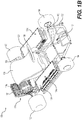
- Figures 1A and 1B show the general construction of an electric kart 100, according one implementation. Some implementations of the electric kart 100 could be referred to as a go-kart. It should be understood that the electric kart 100 could have a construction other than the one described below. For example, Figures 2A and 2B show another implementation of the electric kart 200, which is described later in this document.
- Electric kart 100 has a chassis 102 composed at least in part of a tubular structure, also known as a frame 102.
- the frame 102 is made from a plurality of hollow cylindrical steel members and steel brackets that are welded to each other.
- hollow cylindrical members could be replaced by other types of members such as solid cylindrical members, hollow tubes having a cross-section other than circular, and beams, for example. It is also contemplated that the members and brackets could be made of another type of metal, such as aluminum for example.
- the members and brackets could be made of a non-metallic material, such as composite materials or plastics for example. It is also contemplated that at least some of the members and brackets could be joined to each other by means other than welding, such as by fastening and bonding for example.
- the frame 102 could have more or less members and brackets than illustrated in Figures 1A to 1C , depending on, for example, the type of materials used, the required strength and rigidity of the frame 102 and the weight of the components attached to the frame 102.
- a pair of front wheels 104 is rotatably connected to the frame 102.
- a steering wheel 106 is operatively connected to the front wheels 104 for steering the electric kart 100.
- a driver's seat 108 is connected to the frame 102 rearward of the steering wheel 106. In a front portion 108 of the electric kart 100, in front of the driver seat 108, there is an accelerator pedal 110 and a brake pedal 112.
- the drive assembly 116 Disposed in a rear portion 114 of the frame 102, rearward of the driver seat 108, is a drive assembly 116 for driving the electric kart 100.
- the drive assembly 116 includes an electric motor 116a that is positioned rearward of the driver seat 108.
- a rear-wheel drive shaft 118 extends through and is supported by the drive assembly 116.
- a pair of rear wheels 120 is operatively connected to the frame 102 and is driven by the rear-wheel drive shaft 118.
- the electric motor 116a is operatively connected to the rear-wheel drive shaft 118 to drive the rear wheels 120.
- the electric kart 100 could include a twin-engine drive system (with two drive assemblies 116 behind and to either side of the driver's seat 108). In such an implementation, two rear-wheel drive shafts 118 would be installed on both sides of the electric kart 100, in the two drive assemblies 116.
- Each of the two batteries 122, 124 supply electric power to the electric motor 116a.
- Each of the two batteries 122, 124 includes a battery management module 164 and a plurality of battery cells 146.
- the battery management module 164 is configured to balance the voltage of the battery cells 146, control recharging of the battery cells 146, control the operating temperature of the battery cells 146, and shut down the electric kart 100 in case of battery overload, electrical disconnect, or overheat conditions. It is contemplated that the battery management module 164 could be a different battery management module 164 that could be configured to perform a different set of functions.
- the battery management module 164 includes a quick-connect electrical connector 166 that is removably electrically mated with a matching quick-connect electrical connector 168 positioned on the frame 102 of the electric kart 100.
- the matching quick-connect electrical connector 168 is electrically connected to the electric motor 116a. It is contemplated that the battery management module 164 may be electrically connected to the electric motor 116a via any other suitable electrical connection.
- the battery cells 146 of each of the batteries 122, 124 are rechargeable 3.6-Volt battery cells, having a generally cylindrical shape.
- the battery cells 146 of each of the batteries 122, 124 are electrically interconnected in a combination of electrical parallel and electrical series connections to provide that battery 122, 124 with a battery output voltage of 50.4 Volts ("V").
- each of the batteries 122, 124 includes seven sleeves 150a.
- Each of the sleeves 150a contains twenty-four battery cells 146 grouped into two groups 146f.
- Each of the groups 146f has twelve battery cells 146.
- Each of the sleeves 150a completely surrounds the battery cells 146 that are received in that sleeve 150a, and contacts each one of the battery cells 146.
- one or more of the sleeves 150a could only partially surround the battery cells 146 received in each of the one or more sleeves 150a. This arrangement could, for example, provide auxiliary air passages (not shown) through each of the one or more sleeves 150a to cool the battery cells 146 received in the one or more sleeves 150a.
- the battery cells 146 in each of the groups 146f of battery cells 146 are interconnected electrically in parallel, such that each group outputs a total of 3.6 V.
- the battery 122 has a total of fourteen groups 146f of battery cells 146.
- the fourteen groups 146f are interconnected electrically in series to output a total of 50.4 V (14 x 3.6 V) to the battery management module 164.
- the series electrical interconnection of the groups 146f of battery cells 146 is achieved via electrically conductive metal rails ("electrical rails") 158, which are described later in this document. It is contemplated that the battery cells 146 could be electrically interconnected using any other suitable electrical connectors.
- the electrical rails 158 and the electrical interconnection of the battery cells 146 in this implementation are the same as the electrical rails 158 and the electrical interconnection of the battery cells 146 of the implementation of the battery 122 shown in Figures 3A to 3F , and is thus omitted here.
- Each of the batteries 122, 124 has a plurality of air passages 124a through which air passes when the electric kart 100 is in motion to cool the at least some of the battery cells 146.
- the air passages 124a are described in more detail later in this document.
- the battery cells 146 could be any suitable type of battery cell. It is contemplated that the battery cells 146 could be electrically interconnected in any suitable way to provide a different output voltage and amperage, for example to suit a different electric motor 116a.
- the two batteries 122, 124 of the electric kart 100 are connected electrically in series to the electric motor 116a, to provide a total of 100.8 V (50.4 V x 2) to the electric motor 116a. It is contemplated that the batteries 122, 124 could be electrically connected to the electric motor 116a via any other suitable electrical connection, such as a parallel or a combination series-parallel connection (not shown). Other electrical connections could be used to suit other electric motors 116a.
- the electric motor 116a in this implementation of the electric kart 100 is an Alternating-Current ("AC") motor 116a, and more particularly a 9kW (at 7,800 rotations per minute) permanent magnet synchronous motor (PMSM) 116a.
- AC Alternating-Current
- PMSM permanent magnet synchronous motor
- this implementation of the electric kart 100 includes a power inverter 132 electrically connected between the two batteries 122, 124 and the electric motor 116a.
- the power inverter 132 converts the Direct-Current ("DC") of the two batteries 122, 124 into AC.
- DC Direct-Current
- the electric motor 116a could be a DC motor, in which case no power inverter would be required to power the DC motor from the batteries 122, 124. It is contemplated that the electric motor 116a could be a different size electric motor.
- the driver seat 108 has a first lateral side 128 and a second lateral side 130 opposite the first lateral side 128.
- Each of the batteries 122, 124 is mounted to the frame 102 on one of the first and second lateral sides 128, 130 of the driver seat 108.
- Battery 122 is on the first lateral side 128.
- Battery 124 is on the second lateral side 140. It is contemplated that each of the batteries 122, 124 could be mounted to the frame 102 partially on one of the first and second lateral sides 128, 130 of the driver seat 108.
- the electric kart 100 could be implemented with only one battery, or more than two batteries, instead of the two batteries shown in Figures 1A to 1C . It is also contemplated that in implementations in which the electric kart 100 has two or more batteries, the batteries need not be mirror images of each other and need not be of one and the same implementation.
- each of the batteries 122, 124 is positioned parallel to a straight forward driving direction, illustrated by reference arrow 134 in Figure 1A , of the electric kart 100, and is substantially horizontal (on a wide side 124c of each battery 122, 124) relative to level terrain.
- the batteries 122, 124 could be positioned in any other orientation (which may include, for example, tilting and pivoting of the batteries 122, 124), so long as air flows through the air passages 148 of each of the batteries 122,124 when the electric kart 100 is in motion. Air passages 148 are described later in this document.
- FIGS 2A and 2B show another implementation of the electric kart 200.
- Electric kart 200 is the same as electric kart 100, except that it has four batteries 202, 204, 206, 208 that power its electric motor 116a and each of the four batteries 202, 204, 206, 208 is oriented substantially vertically on a long side 210 of each of battery 202, 204, 206, 208, relative to terrain (not shown).
- the electric kart 200 has two batteries 202, 204 and 206, 208 on each longitudinal side of the electric kart 200.
- battery orientations could be selected, for example, to improve aerodynamics of a given implementation of the electric kart 100, 200, or to improve airflow through the air passages 148 of the batteries 122, 124, 202, 204, 206, 208.
- the batteries 122, 124 could be used with features such as air manifolds (not shown, described later in this document), so long as air flows through the air passages 148 of each of the batteries 122, 124, 202, 204, 206, 208 when the electric kart 100 is in motion.
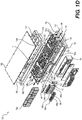
- the batteries 122, 124 are now further described with reference to Figures 1C to 1F .
- the batteries 122, 124 are mirror images of each other and have the same features. Thus, for simplicity, only the battery 122 will be described.
- a description of the battery 122 corresponds to a description of the battery 124.
- the battery 122 has a support structure 144.
- the support structure 144 has a bottom portion 144a and a top portion 144b spaced from the bottom portion 144a.
- the battery 122 is mounted to the frame 102 of the electric kart 100 via the bottom portion 144a of the support structure 144.
- the electric kart 100 includes a battery locking mechanism 138 operatively connected to the frame 102 of the electric kart 100.
- the battery 122 is mounted to the frame 102 of the electric kart 100 via the battery locking mechanism 138.
- the battery locking mechanism 138 is operable to lock the battery 122 to the frame 102, and to unlock the battery 122 from the frame 102.
- the battery locking mechanism 138 includes two actuators 140, 142. Each of the actuators 140, 142 is movable between a locked position, in which that actuator 140, 142 compresses the battery 122 against the frame 102 of the electric kart 100 and thereby locks the battery 122 to the frame 102, and an unlocked position in which that actuator 140, 142 is disengaged from the battery 122. When both of the actuators 140, 142 are in the unlocked position, the battery 122 can be removed from the frame 102.
- Each of the actuators 140, 142 includes a lever 140a, 142a that is movable between a locked position and an unlocked position.
- Each of the actuators 140, 142 also includes a compression block 140b, 142b that is operable by a corresponding one of the levers 140a, 142a to compress the bottom portion 144a of the support structure 144 of the battery 122 against the frame 102 of the electric kart 100 by moving the corresponding lever 140a, 142a to the locked position.
- Each compression block 140b, 142b is also operable by the corresponding lever to disengage the bottom portion 144a of the support structure 144 from the frame 102 by moving the lever 140a, 142a back to its unlocked position.
- the battery locking mechanism 138 could have a different number of actuators 140, 142. It is contemplated that any other suitable locking mechanism could be used to mount the batteries 122, 124 to the electric kart 100. It is contemplated that the locking mechanisms could be replaced by one or more of, or a combination of fasteners, such as bolts or screws.
- the support structure 144 could be made integral with the frame 102 of the electric kart 100.
- the support structure 144 of the battery 122 includes four handles 144c for carrying the battery 122 when the battery 122 is disengaged from the electric kart 100. It is contemplated that in other implementations, the battery 122 could have no handles, or a different number of handles.
- the battery 122 has a plurality of battery cells 146 positioned on the support structure 144 such that there are three air passages 148 defined between the battery cells 146. Air passes through each of the three air passages 148 when the electric kart 100 is in motion, to cool some of the battery cells 146.
- the battery 122 could have only one air passage, two air passages, or more than the three air passages 148.
- Each of the air passages 148 has two open ends 124a,b that are fluidly interconnected to allow air to pass between the open ends 124a,b.
- the battery 122 is positioned on the frame 102 of the electric kart 100 such that when the electric kart 100 moves straight forward, the open ends 124a of the air passages 148 face the straight forward direction and collect air such that the air passes through the open ends 124a and exits from the corresponding open ends 124b.
- the battery 122 could be positioned on the frame 102 of the electric kart 100 such that when the electric kart 100 moves straight forward, the open ends 124b would face the straight forward direction to collect air such that the air would pass through the open ends 124b and would exit from the corresponding open ends 124a.
- the battery 122 has seven heat exchangers 150, arranged into four rows and two columns.
- the rear column has four heat exchangers 150 and the front column has three heat exchangers 150 and a battery management module 164.
- each of the seven heat exchangers 150 is the same, but it is contemplated that the heat exchangers 150 could differ. It is contemplated that the battery 122 could have fewer or more heat exchangers 150.
- one of the heat exchangers 150 and the battery management module 164 are positioned on the support structure 144 of the battery 122 to define part of one of the air passages 148. Air passing in that air passage 148 cools the battery management module 164 when the electric kart 100 is in use.
- each of the heat exchangers 150 includes a sleeve 150a that extends between the bottom portion 144a and the top portion 144b of the support structure 302.
- the sleeves 150a are positioned on the support structure 144 such that they define the three air passages 148 therebetween.
- each of the heat exchangers 150 includes two pairs of racks 146a,b and 146c,d.
- the racks 146a, 146c are bottom racks, and the racks 146b, 146d are top racks.
- Each of the racks 146a to 146d is molded from plastic and defines a plurality of receptacles 146e.
- Each of the receptacles 146e is sized to receive a battery cell 146 therein.
- the racks 146a to 146d could be made from a material other than plastic such as a material having good heat conduction properties.
- each of the sleeves 150a has two sleeve recesses 150b.
- Each of the two sleeve recesses 150b is shaped to receive one of the racks 146a to 146d therein.
- each pair of racks 146a,b and 146c,d sandwiches a central part of a corresponding sleeve 150a and is received in the corresponding sleeve 150a.
- the sleeves 150a are shaped to contact the surface of the battery cells 146 for improved heat transfer between the battery cells 146 and air passing through the air passages 148. This contact area is between the pair of racks 146a,b or 146c,d, as shown by reference numeral 150c in Figure 1E .
- these gaps can be filled with a filler material, such as a known heat conductive filler material to further improve heat transfer between the battery cells 146 and the air passing through the air passages 148.
- a filler material such as a known heat conductive filler material
- the filler material is illustrated with reference numeral 150d in Figure 1E . It is contemplated that the filler material 150d could be omitted. It is also contemplated that the battery cells 146 could be completely spaced from the sleeves 150a and the filler material 150d could be used to fill the resulting gap.
- each structural recess 152 is shaped to receive a sleeve 150a therein.
- each structural recess 152 is defined by a structural aperture 151 and a corresponding access panel 160, 162.
- Each structural aperture 151 extends between a sleeve-facing surface 154 of the support structure 144 and an outward-facing surface 156 of the support structure 144.
- the outward-facing surface 156 is opposite the sleeve-facing surface 154.
- the structural apertures 152 serve as access openings to the battery cells 146 and electrical connections (which will be described later in this document) of the battery 122.
- the battery 122 includes two access panels 160 and 162.
- the bottom access panel 160 is removably attached to the bottom portion 144a of the support structure 144 via a plurality of screws (not shown).
- the top access panel 162 is removably attached to the top portion 144b of the support structure 144 via a plurality of screws (not shown).
- Each of the access panels 160, 162 is a sheet of metal. It is contemplated that any other suitable construction could be used.
- the support structure 144 could have no access panels. It is contemplated that the support structure 144 could have one access panel, or more than two access panels. It is contemplated that the support structure 144 could have more than one type of access panel.
- the structural recesses 152 would be adopted accordingly for each implementation of the support structure 144.
- the support structure 144 is made of a plastic that is sufficiently strong to keep the battery 124 together when the electric kart 100 is in use.
- the sleeves 150a are made of aluminium. It is contemplated that various parts of the battery 122 could be made from any other suitable materials.
- the shape of the recesses 152 is selected such that when one of the racks 146a to 146d is received in a recess 152, that rack 146a, b, c, or d is substantially flush with the sleeve-facing surface 154 of the support structure 144. It is contemplated that one or more of the recesses 152 could have a shape selected such that the rack 146a to 146d received in that recess 152 is above or below the sleeve-facing surface 154.
- the recesses 152 all have the same shape and the sleeves 150a all have the same shape.
- the shape of the recesses 152 and the shape of the sleeves 150a are selected to fit one into the other, as shown in Figure 1E . It is contemplated that the recesses 152 and the sleeves 150a could have different shapes selected to fit one into the other. It is also contemplated that the sleeves 150a and/or the recesses 152 could have any suitable known alignment feature(s) (not shown) to aid in aligning and/or retaining the sleeves 150a, the racks 146a to 146d, and the recesses 152 relative to each other.
- the battery management module 164 is received in a corresponding pair of recesses 164a and 164b in the support structure 144.
- the top recess 164b is defined by a structural aperture 151 and the top access panel 162. It is contemplated that the top recess 164b could be defined solely by the top portion 144b of the support structure 144.
- the recesses 164a and 164b receiving the battery management module 164 are substantially rectangular. It is contemplated that the recesses 164a and 164b could have the same shape as the recesses that receive the sleeves. The battery management module 164 would be adapted accordingly, to fit and to be received in these recesses 164a, 164b. It is contemplated that the implementation of the battery 122 having recesses 152, 164a, 164b of one and the same shape could allow for the battery management module 164 to be receivable in any one of the recesses 152, 164a, 164b.
- each rack 146a to 146d in each pair of the racks 146a to 146d has a groove 146e and the sleeve 150a corresponding to that pair of racks 146a to 146d is received in the groove 146e.
- the sleeve 150a is thus sandwiched by that pair of racks 146a to 146d.
- the battery 122 need not have racks 146a to 146d on both the top and the bottom of the battery cells 146. It is contemplated that the support structure 144 and the sleeves 150a could be adapted in such implementations to retain the battery cells 146 and the sleeves 150a in place when the battery 122 is in use and/or that one or more additional elements other than racks could be provided to retain the battery cells 146 and the sleeves 150a in place.
- the battery 122 may be assembled using any suitable known method and any suitable combination of known connectors, such as fasteners and adhesives.
- the top 144b and bottom 144a portions of the support structure 144 may be screwed to the sleeves 150a so as to hold the battery 122 together.
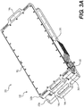
- the battery 300 is the same as the battery 122 except with respect to the implementation of the support structure 302, the racks 326, 328 and the battery management module 304. These differences will be described below.
- the battery 300 has the same battery cells 146 as the battery 122.
- the fourteen groups of battery cells 146 are positioned in an alternating up-down configuration, as shown with "+” and "-” signs in Figure 3D .
- the groups that are positioned “up” are positioned such that their positive terminals face away from the bottom portion 144a of the support structure 302.
- the groups that are positioned “down” are positioned such that their positive terminals face toward the bottom portion 144a of the support structure 302.
- the positive terminals are shown with "+” signs on Figure 3D .
- the negative terminals are shown with "-" signs on Figure 3D .
- the battery 300 includes electrical rails 344a to 344o, which have a different appearance but are electrically the same as the electrical rails 158 of the battery 122.
- electrical rails 344a to 344g are positioned on the top portion 144b side of the support structure 302.
- electrical rails 344h to 344o are positioned on the bottom portion 144a side of the support structure 302.
- the electrical rails 344a to 344o are made of metal and electrically connect the fourteen groups of battery cells 146 in series to provide the overall battery output voltage (50.4-V). It is contemplated that the electrical rails 158, 344a to 344o could be made from any suitable electrically conductive material, or combination of materials. It is contemplated that the electrical rails 158, 344a to 344o could be substituted with any other suitable electrical connectors (for example, electrical wires).
- each of the battery cells 146 are electrically connected to a respective one of the electrical rails 344a to 344o via tabs 346. To maintain clarity, only one of the tabs 346 is labelled in Figures 3D and 3E .
- the tabs 346 are strips of metal.
- Each of the tabs 346 is soldered to a corresponding terminal of one of the battery cells 146 and to a corresponding one of the electrical rails 344a to 344o. It is contemplated that the battery cells 146 could be electrically connected to the electrical rails 344a to 344o via any other suitable electrical connector.
- the electrical rails 344a to 344o are positioned as shown in Figures 3D and 3E such that the fourteen groups of battery cells 146 are electrically interconnected in series to result in the 50.4-V output of the battery 300.
- the electrical rails 344a to 344o could be positioned differently depending on each particular battery cell arrangement and each particular desired overall battery output voltage.
- the battery cells 146 could be arranged in any suitable arrangement.
- the overall battery voltage requirement may be dictated by, for example, the type of motor(s) or other electrical devices that the battery 300 may be designed to power.
- the battery 300 also includes a battery management module 304.
- the battery management module 304 is mounted to the support structure 302.
- the electrical rails 344a to 344o connect the fourteen groups of battery cells 146 (two of which groups are shown with reference numerals 300a, 300b on Figure 3D ) electrically in series to the battery management module 304 to provide the battery output voltage (in this case, the 50.4-V) to the battery management module 304.
- the battery management module 304 includes a plurality of heat transfer fins 310 configured to cool the battery management module 304 when the electric kart 100 is in use. It is contemplated that other suitable battery management modules 304 could have different heat transfer fins 310, or could have no heat transfer fins 310.
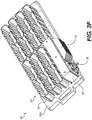
- Each of the sleeves 324 of the battery 300 includes two racks 326, 328.
- the racks 326, 328 are molded plastic inserts that are shaped to retain the battery cells 146 in place when the battery 300 is in use.
- the racks 326, 328 are shaped to reduce clearances between the battery cells 146 and the sleeves 324 so as to reduce the magnitudes of vibrations of the battery cells 146 when the battery 300 is in use. It is contemplated that the racks 326, 328 could be any other suitable components designed to carry out the functions these racks 324, 326.
- each sleeve 324 in this implementation has two racks 326, 328, it is contemplated that one or more of the sleeves 324 could have no racks, one rack, or more than two racks. It is also contemplated that the rack(s) 326, 328 could have shapes other than the shapes shown in the Figures.
- each sleeve 324 includes recesses 330, and each of the recesses 330 has a battery cell 146 received therein.
- each of the racks 326, 328 includes corresponding recesses 332.
- the racks 326, 328 and the sleeve 324 provide receptacles 334 in which the battery cells 146 are received. For clarity, only some of the battery cells 146, recesses 330, and receptacles 334, have been labeled.
- the battery cells 146 are slidably received in the receptacles 334. It is contemplated that the battery cells 146 could be mounted to the sleeves 324. It is contemplated that the battery cells 146 could be mounted to the racks 326, 328. It is contemplated that the battery cells 146 could be mounted to the racks 326, 328 and the sleeves 324.
- each of the battery cells 146 is mounted to a respective one of the racks 326, 328 via a suitable known mechanism, such as tie straps or an adhesive (not shown).
- a suitable known mechanism such as tie straps or an adhesive (not shown).
- each receptacle 334 contains one of the battery cells 146. That is, each sleeve 324 contains one layer of battery cells 146.
- one or more receptacles 334 could contain two or more battery cells 146. That is, it is contemplated that one or more of the sleeves 324 could contain two or more layers of battery cells 146. The battery cells 146 could be stacked one on top of another.
- each of the sleeves 324 has inwardly facing protrusions 336, 338.
- the protrusions 336, 338 are shaped and positioned in the sleeve 324 to divide the battery cells 146 inside that sleeve 324 into two sets of battery cells 146, to reduce movement of the battery cells 146 when the electric kart 100 is in use.
- the two sets of battery cells 146 are shown with reference outlines 340 and 342.
- This implementation of the battery 300 is assembled by pressing the bottom side of the sleeves 324 into the bottom portion 302a of the support structure 302, engaging the battery cells 146 with the racks 326, 328, then inserting the racks 326, 328 and the battery cells 146 into the sleeves 324, electrically interconnecting the battery cells 146 as described above, and pressing the top portion 302b of the support structure 144 onto the top side of the sleeves 324.
- top portion 302b and the bottom portion 302a of the support structure 302 thereby sandwich the sleeves 324, the electrical rails 344a to 344d, the battery cells 146, and the battery management module 304, and thereby hold the battery 300 together.
- deformation of the plastic support structure 302 holds the sleeves 324 attached to and partially inserted into each of the bottom 30a and top 302b portions of the support structure 302, and thereby holds the battery 300 together.
- an adhesive or any other suitable additional structural elements, such as links and rods, could be used to strengthen the assembly of the battery 300. It is contemplated that other manufacturing and assembly methods and other hardware and materials could be used to manufacture and assemble the battery 300.
- top portion 302b and the bottom portion 302a could be made integral to each other - in this implementation, suitable access openings would be provided to allow for the insertion and the removal of the battery cells 146.
- the structural apertures 152 could be adopted for this purpose.
- the battery 400 is the same as the battery 300, except insofar as it is described next.
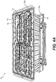
- the battery 400 has an additional sleeve 402 that is positioned in place of the battery management module 304 of the battery 300.
- the battery management module 404 of the battery 400 is sized and received inside the additional sleeve 402.
- the additional sleeve 402 defines an air passage (not shown, because it is the same as the other air passages described above) between the additional sleeve 402 and another one of the sleeves 424.
- sleeves 424 are aluminium, and the additional sleeve 402 is plastic. It is contemplated that sleeves 424 and the additional sleeve 402 could be made using any suitable material, or combination of materials.
- Each of the sleeves 424 has two layers of battery cells 146 received therein.
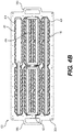
- the battery cells 146 are arranged as shown with "+" and "-" signs in Figure 4B .
- the battery cells 146 in each layer of battery cells 146 within each of the sleeves 424 are interconnected electrically in parallel via the electrical rails 426.
- the two layers of battery cells 146 in each of the sleeves 424 are interconnected in series by stacking the top layer of the battery cells 146 (this layer is seen in Figure 4B ) on top of the bottom layer of battery cells 146.
- the seven groups of battery cells 146 are interconnected in series via the layout of the electrical rails 426 shown in Figures 4B and 4C , such that the battery outputs 50.4-V (7 x 7.2-V) to the battery management module 404.
- the electrical rails 426 shown in dashed lines on Figure 4C are the electrical rails 426 that are positioned on the bottom side of the battery cells 146, between the battery cells 146 and the bottom portion 302a of the support structure 302.
- Battery 500 is the same as battery 300, except insofar as it is described next.
- the battery management module 504 is positioned on a different side of the battery 500. It is contemplated that the battery management module 504 could be positioned in any suitable position on the battery 500, and also does not need to be a part of the battery 500.
- Each of the sleeves 524 of battery 500 has a single battery cell 514 received therein.
- Each battery cell 514 in this implementation is one and the same implementation of battery cell, and thus only one of the battery cells 514 is labeled.
- Each of the battery cells 514 is shaped to contact the sleeve 524 in which that battery cell 514 is received to help transfer heat from that battery cell 514 to that sleeve 524 and into air that will pass, when the electric kart 100 is in use, through one or more air passages 516, 518, 520 that is defined by that sleeve 524.
- the battery 500 has no racks.
- Battery 600 is the same as battery 300, except insofar as it is described next.
- the battery 600 has two sleeves 624 positioned on the support structure 602a of the battery 600 to define air passage 616 therebetween. When the battery 600 is in use, air passes through air passage 616 to cool the battery cells 614.
- the battery 600 has no racks.
- the battery management module 604 of this battery 600 is positioned on the support structure 602 to define air passage 618 between the battery management module 604 and one of the two sleeves 624. When the battery 600 is in use, air passes through air passage 618 to cool some of the battery cells 614 and the battery management module 604.
- the battery management module 604 is the same as battery management module 304, except that it is selected (in terms of size and functionality) to serve the different number of battery cells 614 of battery 600.
- the support structure 602 of this battery 600 is likewise adapted to receive the two sleeves 624 and the battery management module 604, instead of the seven sleeves 324 and the battery management module 304 of battery 122.
- Each of the two sleeves 624 of this battery 600 is shaped such that the battery cells 614 in that sleeve 624 are positioned in two rows of battery cells. The two rows are staggered such that each of the battery cells 614 in the two rows contacts two other battery cells 614. It is contemplated that the sleeves 624 could be shaped to receive one row, or more than two rows, of battery cells 614.
- the sleeves 624 could be shaped such that the battery cells 614 in the one or more rows of battery cells 614 would contact only one other battery cell 614, or more than two other battery cells 614, in the one or more rows of battery cells 614. It is also contemplated that the sleeves 624 need not be shaped to receive the same number of battery cells 614, or a single type of battery cells 614.
- Battery 700 is the same as battery 300, except insofar as it is described next.
- Battery 700 has twenty-four sleeves 724 positioned on the support structure 702 of the battery 700 to define a plurality of air passages 716a, 716b therebetween.
- the sleeves 724 define both longitudinal air passages 716a and transverse air passages 716b.
- the battery cells of this implementation have not been shown.
- the sleeves 724 could be adapted to receive more than one type of battery cells, and the battery cells could be electrically interconnected using any suitable electrical interconnection to provide a desired overall battery output voltage.
- any suitable electrical output could be used.
- the electrical connection could be a combination of wires, or any suitable electrical connector (not shown).
- one or more suitable battery management modules could be positioned on the electric kart 100, 200 (for example, could be mounted to the frame 102 of the electric kart 100, 200), and could be electrically connected to the battery 700 to power the electric kart 100, 200.
- one or more heat exchangers of the battery could include a plurality of heat transfer fins (not shown) configured to transfer heat away from the battery cells when the battery is in use.
- the battery could also include a housing that could cover the battery cells of that battery.
- the geometry and materials of the housing could be selected to protect the battery cells from, for example, mechanical impact and weather elements when the battery is in use.
- the housing could have an air inlet, an air outlet, and a ventilated space extending between the air inlet and the air outlet.
- the battery cells could be positioned in the ventilated space, such that the air passage(s) could pass at least some of the air that would pass through the ventilated space when the battery is in use.
- the housing could have an air manifold fluidly connected to the air inlet of the housing.
- the air manifold could be sized and positioned relative to the electric kart to increase airflow through the ventilated space of the housing when the electric kart is in motion, relative to airflow that could occur through that ventilated space if no air manifold was present.
- the heat exchangers could be the racks, similar to the racks described above.
- the battery cells could be mounted to the racks, and (due to the lack of sleeves) could thus be exposed to air.
- the battery cells and the rack(s) define the air passage(s) of the battery.
- the rack(s) could be integrally made. That is, the rack(s) could be a single rack comprising receptacles or other features to allow the battery cells to be received therein or to be mounted thereto, as may be applicable to each implementation of the battery.
- the battery could be used in applications other than electric kart applications. It is contemplated the battery could be adapted (for example, in terms of sizes, materials, capacities, etc.) to suit each application, or applications, for which the battery may be designed.
- the battery could have any other number of sleeves, more than one type of sleeves, and any number of battery cells, to suit each particular application of the battery.
- the components of the battery and their characteristics could be selected to suit each particular application of the battery.
- the geometry and sizing of the air passage(s) of the battery could be selected at least in part based on a desired range of operating temperatures of the battery cells, on expected heat generation rates of the battery cells, and on airflow rates and air temperatures expected to occur in the air passage(s) of the battery when the battery is in use.
- Suitable materials for the components of the battery could be selected based on similar considerations.
- parts of the battery could be configured to be assembled in other ways than the configurations described in this document, and could be made from other suitable materials than the materials described in this document.
- the batteries described in this document could be manufactured and implemented using any suitable materials, components, and engineering design, selection, manufacturing, assembly, wiring, and programming methods.
- the electric kart described in this document could be manufactured and implemented using any suitable materials, components, and design, selection, manufacturing, assembly, wiring, and programming methods.
Landscapes
- Engineering & Computer Science (AREA)
- Power Engineering (AREA)
- Transportation (AREA)
- Mechanical Engineering (AREA)
- Chemical & Material Sciences (AREA)
- Sustainable Energy (AREA)
- Sustainable Development (AREA)
- Life Sciences & Earth Sciences (AREA)
- Chemical Kinetics & Catalysis (AREA)
- Electrochemistry (AREA)
- General Chemical & Material Sciences (AREA)
- Manufacturing & Machinery (AREA)
- Combustion & Propulsion (AREA)
- Microelectronics & Electronic Packaging (AREA)
- Aviation & Aerospace Engineering (AREA)
- Secondary Cells (AREA)
- Battery Mounting, Suspending (AREA)
Abstract
Description
- The technology disclosed herein relates to batteries for powering electric karts and electric karts having such batteries.
- Many electric karts and batteries for electric karts are known.
- For example,
U.S. Patent Publication No. 2013/0025950A1, published on January 31, 2013 , describes an electric kart with one or more lightweight, quick-change batteries or battery packs mounted on the kart frame. The kart body has battery pack access openings to provide easy access to remove and replace battery packs during racing operations. The batteries are easily removed and replaced so that a particular kart can be "refueled" in a matter of seconds. The batteries being removed are placed on a charger, and can be placed back into service relatively quickly. Lithium Ion batteries could be used for the battery packs. - Prior art electric karts and batteries have a number of limitations. For example, one problem often occurs in racing operations, where electric kart batteries tend to heat up beyond temperatures at which the batteries operate most efficiently. Another problem is that, at least in some types of batteries, overheating causes a reduction of usable battery life and electrical charge storage capacity.
- In view of the problems with the prior art, it would be desirable to provide electric karts and batteries that could be used with such karts that attempt to address these problems.
- In this document, the term battery cell refers to any suitable electrical device that stores electrical energy and provides an electrical output at a given voltage when charged. The term battery refers to an arrangement of battery cells that are electrically interconnected to provide a battery output voltage. The term battery output voltage refers to a voltage that results from and is determined by how the battery cells are interconnected (e.g., via parallel electrical connections only, via series electrical connections only, or via a combination of parallel and series electrical connections).
- For example, where two battery cells are interconnected electrically in parallel, the battery output voltage is the same as the voltage of each of the two battery cells. As another example, where two battery cells are interconnected electrically in series, the battery output voltage is a sum of the voltages of the two battery cells.
- In one aspect, the present technology provides an electric kart having at least one air-cooled battery. Each battery includes a plurality of battery cells and at least one air passage defined between the battery cells. When the electric kart is in motion, ambient air passes through the air passage of each battery to cool the battery cells of that battery. The cooling provided by the air passage may reduce an extent of heating up of battery cells, and may also reduce a risk of overheating of battery cells.
- Each battery is positioned such that when the electric kart is in motion, the motion of the electric kart induces airflow through the air passage of each battery. More particularly, each air passage has two open ends that are fluidly interconnected, and the batteries are positioned such that one open end of each passage faces straight forward. As a result, the open end of the air passage moves against air and some of that air passes through the air passage.
- It is contemplated that the batteries described in this document could be manufactured and sold separately from electric karts. It is also contemplated that the batteries described in this document could be used in applications other than electric kart applications.
- In one aspect, the present technology provides an electric kart that comprises a frame, a driver seat mounted to the frame, two front wheels and two rear wheels operatively connected to the frame, an electric motor operatively connected to the two rear wheels to drive the two rear wheels, and at least one battery operatively connected to the electric motor to power the electric motor to drive the electric kart.
- The at least one battery has a support structure mounted to the frame of the electric kart, and a first plurality of battery cells and a second plurality of battery cells positioned on the support structure such that there is an air passage defined between the first plurality of battery cells and the second plurality of battery cells.
- The air passage is configured for allowing passage of air to cool at least some battery cells of at least one of the first and second pluralities of battery cells when the electric kart is in motion.
- In another aspect, the air passage has a first open end and a second open end fluidly connected to the first open end. In a further aspect, the air passage is positioned such that when the electric kart is in a straight forward motion, air passes in the air passage from the first open end to the second open end.
- In some implementations, the at least one battery includes a first heat exchanger and a second heat exchanger positioned on the support structure. The first heat exchanger and the second heat exchanger define the air passage therebetween. In some implementations, the first plurality of battery cells is disposed inside the first heat exchanger, and the second plurality of battery cells is disposed inside the second heat exchanger.
- In some implementations, the support structure of the at least one battery includes a bottom portion mounted to the frame of the electric kart and a top portion spaced from the bottom portion. In such implementations, the first heat exchanger includes a first sleeve that extends between the bottom and top portions of the support structure, and the second heat exchanger includes a second sleeve that extends between the bottom and top portions of the support structure. The first plurality of battery cells is received in the first sleeve. The second plurality of battery cells is received in the second sleeve.
- In some implementations, the first heat exchanger includes a first rack disposed inside the first sleeve, the second heat exchanger includes a second rack disposed inside the second sleeve, at least some battery cells of the first plurality of battery cells are mounted to the first rack, and at least some battery cells of the second plurality of battery cells are mounted to the second rack.
- In some implementations, the first sleeve has a first plurality of recesses, each recess of the first plurality of recesses has a battery cell of the first plurality of battery cells received therein, the second sleeve has a second plurality of recesses, and each recess of the second plurality of recesses has a battery cell of the second plurality of battery cells received therein.
- In some implementations, the first heat exchanger includes a first rack disposed inside the first sleeve, the first sleeve has a first plurality of recesses, the first rack and the first plurality of recesses define a first plurality of receptacles, the first plurality of battery cells is received in the first plurality of recesses, the second heat exchanger includes a second rack disposed inside the second sleeve, the second sleeve has a second plurality of recesses, the second rack and the second plurality of recesses define a second plurality of receptacles, and the second plurality of battery cells is received in the second plurality of recesses.
- In some implementations, each battery cell of the first plurality of battery cells contacts the first sleeve and at least one other battery cell of the first plurality of battery cells, and each battery cell of the second plurality of battery cells contacts the second sleeve and at least one other battery cell of the second plurality of battery cells.
- In some implementations, the first heat exchanger includes a first rack and a second rack, the first sleeve is positioned between the first rack and the second rack, the second heat exchanger includes a third rack and a fourth rack, and the second sleeve is positioned between the third rack and the fourth rack.
- In some implementations, each of the first and second racks includes a plurality of receptacles, each of the receptacles of the first and second racks has one battery cell of the first plurality of battery cells received therein, each of the third and fourth racks includes a plurality of receptacles, and each of the receptacles of the third and fourth racks has one battery cell of the second plurality of battery cells received therein.
- In some implementations, the first plurality of battery cells is arranged into at least two rows of battery cells, and the second plurality of battery cells is arranged into at least two rows of battery cells.
- In some implementations, the at least one air passage is a first air passage defined by the first and second sleeves, and the at least one battery includes: a) a third heat exchanger having a third sleeve that extends between the bottom and top portions of the support structure, the third sleeve and at least one of the first and second sleeves defining a second air passage therebetween, and b) a third plurality of battery cells received in the third sleeve.
- In some implementations, the at least one battery includes a battery management module that is electrically connected to at least some battery cells of the first and second pluralities of battery cells.
- In some implementations, the electric motor is positioned rearward of the driver seat.
- In some implementations, the at least one battery includes a first battery and a second battery, the first battery is mounted to the frame of the electric kart at least partially on one side of the driver seat, and the second battery is mounted to the frame of the electric kart at least partially on another side of the driver seat.
- In some implementations, at least one of: a) the frame of the electric kart, and b) the at least one battery, includes a fastener to fasten the at least one battery to the frame of the electric kart; and the at least one battery is mounted to the frame of the electric kart via the fastener.
- In another aspect, the present technology provides a battery that comprises a support structure, a plurality of battery cells, and a plurality of sleeves, each sleeve of the plurality of sleeves having at least one battery cell of the plurality of battery cells received therein, and the plurality of sleeves being positioned on the support structure to define at least one air passage between at least two sleeves of the plurality of sleeves.
- In some implementations, the battery further comprises at least one rack received in the support structure. In such implementations, the plurality of battery cells is one of: a) mounted to and b) received in, the at least one rack.
- In some implementations, each sleeve of the plurality of sleeves has a plurality of recesses, and each recess of the plurality of recesses has at least one battery cell received therein.
- In some implementations, the battery further comprises a battery management module that is positioned on the support structure and is electrically connected to the plurality of battery cells.
- In some implementations, the battery includes a battery management module sleeve positioned on the support structure to define an additional air passage between the battery management module sleeve and at least one sleeve of the plurality of sleeves, and the battery management module is received in the battery management module sleeve.
- The exemplary implementations described in this document are intended to aid the reader in understanding the principles of the present technology and not to limit its scope to such specifically recited implementations.
- The drawings included herewith are for illustrating various implementations of articles, products, methods, and apparatuses described in the present specification. The drawings could not be to scale. Some features shown in the drawings could be exaggerated, or scaled down, relative to their possible "life" size(s), in order to make these features clearly visible in the drawings.
- In the drawings:
-
Figure 1A is a top plan view of an electric kart, according to one implementation; -
Figure 1B is a perspective view taken from a front, right side of the electric kart ofFigure 1A ; -
Figure 1C is a perspective view taken from a front, left side of a left-side battery of the electric kart ofFigures 1A and1 B; -
Figure 1D is a partially exploded view of the battery ofFigure 1C ; -
Figure 1E is a schematic cross-section of a part of the battery ofFigures 1C and1D , taken along section line 1E-1E ofFigure 1D ; -
Figure 1F is a schematic section view of a part of the battery ofFigures 1C and 1D, taken along section line 1E-1E ofFigure 1D , according to another implementation of the battery; -
Figure 2A is a perspective view of an electric kart, according to another implementation; -
Figure 2B is a top plan view of the electric kart ofFigure 2A ; -
Figure 3A is a perspective view of a battery of the electric kart ofFigures 1A and1B , according to another implementation of the battery; -
Figure 3B is a top plan view of the battery ofFigure 3A , with the battery being partly-disassembled to better show some of its parts; -
Figure 3C is a close-up view ofportion 3C-3C of the battery ofFigure 3B ; -
Figure 3D is a top plan view of the battery ofFigure 3A , with the top portion of the support structure of the battery being removed to better show the top-side electrical rails of the battery; -
Figure 3E is a top plan view of the battery ofFigure 3A , with the top portion of the support structure, the top-side electrical rails, the battery management module, the battery cells, and the racks of the battery being removed to better show the bottom-side electrical rails of the battery; -
Figure 3F is a perspective view of the battery ofFigure 3A , with the battery being partly-disassembled to better show some of its parts; -
Figure 4A is a perspective view of a battery, according to another implementation, with the top-side access panel of the battery being removed to better show the internal structure of this implementation of the battery; -
Figure 4B is a top plan view of the battery ofFigure 4A , with the top portion of the support structure of the battery being removed to better show the top-side electrical rails of the battery; -
Figure 4C is a top plan view of the battery ofFigure 4A , with the top portion of the support structure, the top-side electrical rails, the battery management module, the battery cells, and the racks of the battery being removed to better show the bottom-side electrical rails of the battery; -
Figure 5 is a top plan view of the left-side battery of the electric kart ofFigures 1A and1B , according to another implementation of the battery, with the battery being partly-disassembled to better show some of its parts; -
Figure 6 is a top plan view of a battery, according another implementation, with the battery being partly-disassembled to better show some of its parts; and -
Figure 7 is a top plan view of a battery, according to another implementation, with the battery being partly-disassembled to better show some of its parts. -
Figures 1A and1B show the general construction of anelectric kart 100, according one implementation. Some implementations of theelectric kart 100 could be referred to as a go-kart. It should be understood that theelectric kart 100 could have a construction other than the one described below. For example,Figures 2A and2B show another implementation of theelectric kart 200, which is described later in this document. -
Electric kart 100 has achassis 102 composed at least in part of a tubular structure, also known as aframe 102. Theframe 102 is made from a plurality of hollow cylindrical steel members and steel brackets that are welded to each other. - It is contemplated that at least some of the hollow cylindrical members could be replaced by other types of members such as solid cylindrical members, hollow tubes having a cross-section other than circular, and beams, for example. It is also contemplated that the members and brackets could be made of another type of metal, such as aluminum for example.
- It is contemplated that at least some of the members and brackets could be made of a non-metallic material, such as composite materials or plastics for example. It is also contemplated that at least some of the members and brackets could be joined to each other by means other than welding, such as by fastening and bonding for example.
- It is contemplated that two or more of the members and brackets described below could be cast or otherwise formed as a single component. It is also contemplated that the
frame 102 could have more or less members and brackets than illustrated inFigures 1A to 1C , depending on, for example, the type of materials used, the required strength and rigidity of theframe 102 and the weight of the components attached to theframe 102. - A pair of
front wheels 104 is rotatably connected to theframe 102. Asteering wheel 106 is operatively connected to thefront wheels 104 for steering theelectric kart 100. A driver'sseat 108 is connected to theframe 102 rearward of thesteering wheel 106. In afront portion 108 of theelectric kart 100, in front of thedriver seat 108, there is anaccelerator pedal 110 and abrake pedal 112. - Disposed in a
rear portion 114 of theframe 102, rearward of thedriver seat 108, is adrive assembly 116 for driving theelectric kart 100. Thedrive assembly 116 includes anelectric motor 116a that is positioned rearward of thedriver seat 108. - A rear-
wheel drive shaft 118 extends through and is supported by thedrive assembly 116. A pair ofrear wheels 120 is operatively connected to theframe 102 and is driven by the rear-wheel drive shaft 118. Theelectric motor 116a is operatively connected to the rear-wheel drive shaft 118 to drive therear wheels 120. - It is contemplated that the
electric kart 100 could include a twin-engine drive system (with twodrive assemblies 116 behind and to either side of the driver's seat 108). In such an implementation, two rear-wheel drive shafts 118 would be installed on both sides of theelectric kart 100, in the twodrive assemblies 116. - Two
batteries electric motor 116a. Each of the twobatteries battery management module 164 and a plurality ofbattery cells 146. - The
battery management module 164 is configured to balance the voltage of thebattery cells 146, control recharging of thebattery cells 146, control the operating temperature of thebattery cells 146, and shut down theelectric kart 100 in case of battery overload, electrical disconnect, or overheat conditions. It is contemplated that thebattery management module 164 could be a differentbattery management module 164 that could be configured to perform a different set of functions. - As best seen in
Figure 1C , thebattery management module 164 includes a quick-connectelectrical connector 166 that is removably electrically mated with a matching quick-connectelectrical connector 168 positioned on theframe 102 of theelectric kart 100. - The matching quick-connect
electrical connector 168 is electrically connected to theelectric motor 116a. It is contemplated that thebattery management module 164 may be electrically connected to theelectric motor 116a via any other suitable electrical connection. - The
battery cells 146 of each of thebatteries battery cells 146 of each of thebatteries battery - More particularly, as will be described in more detail below, each of the
batteries sleeves 150a. Each of thesleeves 150a contains twenty-fourbattery cells 146 grouped into twogroups 146f. Each of thegroups 146f has twelvebattery cells 146. - Each of the
sleeves 150a completely surrounds thebattery cells 146 that are received in thatsleeve 150a, and contacts each one of thebattery cells 146. - It is contemplated that one or more of the
sleeves 150a could only partially surround thebattery cells 146 received in each of the one ormore sleeves 150a. This arrangement could, for example, provide auxiliary air passages (not shown) through each of the one ormore sleeves 150a to cool thebattery cells 146 received in the one ormore sleeves 150a. - The
battery cells 146 in each of thegroups 146f ofbattery cells 146 are interconnected electrically in parallel, such that each group outputs a total of 3.6 V. Thebattery 122 has a total of fourteengroups 146f ofbattery cells 146. The fourteengroups 146f are interconnected electrically in series to output a total of 50.4 V (14 x 3.6 V) to thebattery management module 164. - In this implementation, the series electrical interconnection of the
groups 146f ofbattery cells 146 is achieved via electrically conductive metal rails ("electrical rails") 158, which are described later in this document. It is contemplated that thebattery cells 146 could be electrically interconnected using any other suitable electrical connectors. - The
electrical rails 158 and the electrical interconnection of thebattery cells 146 in this implementation are the same as theelectrical rails 158 and the electrical interconnection of thebattery cells 146 of the implementation of thebattery 122 shown inFigures 3A to 3F , and is thus omitted here. - Each of the
batteries air passages 124a through which air passes when theelectric kart 100 is in motion to cool the at least some of thebattery cells 146. Theair passages 124a are described in more detail later in this document. - It is contemplated that the
battery cells 146 could be any suitable type of battery cell. It is contemplated that thebattery cells 146 could be electrically interconnected in any suitable way to provide a different output voltage and amperage, for example to suit a differentelectric motor 116a. - The two
batteries electric kart 100 are connected electrically in series to theelectric motor 116a, to provide a total of 100.8 V (50.4 V x 2) to theelectric motor 116a. It is contemplated that thebatteries electric motor 116a via any other suitable electrical connection, such as a parallel or a combination series-parallel connection (not shown). Other electrical connections could be used to suit otherelectric motors 116a. - The
electric motor 116a in this implementation of theelectric kart 100 is an Alternating-Current ("AC")motor 116a, and more particularly a 9kW (at 7,800 rotations per minute) permanent magnet synchronous motor (PMSM) 116a. - Accordingly, this implementation of the
electric kart 100 includes apower inverter 132 electrically connected between the twobatteries electric motor 116a. Thepower inverter 132 converts the Direct-Current ("DC") of the twobatteries electric motor 116a could be a DC motor, in which case no power inverter would be required to power the DC motor from thebatteries electric motor 116a could be a different size electric motor. - The
driver seat 108 has a firstlateral side 128 and a secondlateral side 130 opposite the firstlateral side 128. - Each of the
batteries frame 102 on one of the first and secondlateral sides driver seat 108.Battery 122 is on the firstlateral side 128.Battery 124 is on the secondlateral side 140. It is contemplated that each of thebatteries frame 102 partially on one of the first and secondlateral sides driver seat 108. - It is contemplated that the
electric kart 100 could be implemented with only one battery, or more than two batteries, instead of the two batteries shown inFigures 1A to 1C . It is also contemplated that in implementations in which theelectric kart 100 has two or more batteries, the batteries need not be mirror images of each other and need not be of one and the same implementation. - In this implementation, each of the
batteries reference arrow 134 inFigure 1A , of theelectric kart 100, and is substantially horizontal (on awide side 124c of eachbattery 122, 124) relative to level terrain. - It is contemplated that the
batteries batteries 122, 124), so long as air flows through theair passages 148 of each of the batteries 122,124 when theelectric kart 100 is in motion.Air passages 148 are described later in this document. - For example,
Figures 2A and2B show another implementation of theelectric kart 200.Electric kart 200 is the same aselectric kart 100, except that it has fourbatteries electric motor 116a and each of the fourbatteries long side 210 of each ofbattery electric kart 200 has twobatteries electric kart 200. - In an aspect, battery orientations could be selected, for example, to improve aerodynamics of a given implementation of the
electric kart air passages 148 of thebatteries - It is contemplated that the
batteries air passages 148 of each of thebatteries electric kart 100 is in motion. - The
batteries Figures 1C to 1F . Thebatteries battery 122 will be described. A description of thebattery 122 corresponds to a description of thebattery 124. - As shown, the
battery 122 has asupport structure 144. Thesupport structure 144 has abottom portion 144a and atop portion 144b spaced from thebottom portion 144a. In this implementation, thebattery 122 is mounted to theframe 102 of theelectric kart 100 via thebottom portion 144a of thesupport structure 144. - As shown in
Figure 1C , theelectric kart 100 includes abattery locking mechanism 138 operatively connected to theframe 102 of theelectric kart 100. Thebattery 122 is mounted to theframe 102 of theelectric kart 100 via thebattery locking mechanism 138. Thebattery locking mechanism 138 is operable to lock thebattery 122 to theframe 102, and to unlock thebattery 122 from theframe 102. - The
battery locking mechanism 138 includes twoactuators actuators actuator battery 122 against theframe 102 of theelectric kart 100 and thereby locks thebattery 122 to theframe 102, and an unlocked position in which thatactuator battery 122. When both of theactuators battery 122 can be removed from theframe 102. - Each of the
actuators lever actuators compression block levers bottom portion 144a of thesupport structure 144 of thebattery 122 against theframe 102 of theelectric kart 100 by moving the correspondinglever - Each
compression block bottom portion 144a of thesupport structure 144 from theframe 102 by moving thelever - It is contemplated that the
battery locking mechanism 138 could have a different number ofactuators batteries electric kart 100. It is contemplated that the locking mechanisms could be replaced by one or more of, or a combination of fasteners, such as bolts or screws. - It is contemplated that in other implementations, the
support structure 144 could be made integral with theframe 102 of theelectric kart 100. - The
support structure 144 of thebattery 122 includes fourhandles 144c for carrying thebattery 122 when thebattery 122 is disengaged from theelectric kart 100. It is contemplated that in other implementations, thebattery 122 could have no handles, or a different number of handles. - As shown in
Figure 1D , thebattery 122 has a plurality ofbattery cells 146 positioned on thesupport structure 144 such that there are threeair passages 148 defined between thebattery cells 146. Air passes through each of the threeair passages 148 when theelectric kart 100 is in motion, to cool some of thebattery cells 146. - It is contemplated that the
battery 122 could have only one air passage, two air passages, or more than the threeair passages 148. - Each of the
air passages 148 has twoopen ends 124a,b that are fluidly interconnected to allow air to pass between theopen ends 124a,b. Thebattery 122 is positioned on theframe 102 of theelectric kart 100 such that when theelectric kart 100 moves straight forward, the open ends 124a of theair passages 148 face the straight forward direction and collect air such that the air passes through the open ends 124a and exits from the corresponding open ends 124b. - It is contemplated that the
battery 122 could be positioned on theframe 102 of theelectric kart 100 such that when theelectric kart 100 moves straight forward, the open ends 124b would face the straight forward direction to collect air such that the air would pass through the open ends 124b and would exit from the corresponding open ends 124a. - The
battery 122 has sevenheat exchangers 150, arranged into four rows and two columns. The rear column has fourheat exchangers 150 and the front column has threeheat exchangers 150 and abattery management module 164. In this implementation, each of the sevenheat exchangers 150 is the same, but it is contemplated that theheat exchangers 150 could differ. It is contemplated that thebattery 122 could have fewer ormore heat exchangers 150. - In this implementation, one of the
heat exchangers 150 and thebattery management module 164 are positioned on thesupport structure 144 of thebattery 122 to define part of one of theair passages 148. Air passing in thatair passage 148 cools thebattery management module 164 when theelectric kart 100 is in use. - As best shown in
Figure 1D , each of theheat exchangers 150 includes asleeve 150a that extends between thebottom portion 144a and thetop portion 144b of thesupport structure 302. Thesleeves 150a are positioned on thesupport structure 144 such that they define the threeair passages 148 therebetween. - In a further aspect, each of the
heat exchangers 150 includes two pairs ofracks 146a,b and 146c,d. Theracks racks racks 146a to 146d is molded from plastic and defines a plurality ofreceptacles 146e. - Each of the
receptacles 146e is sized to receive abattery cell 146 therein. For clarity of the figures, only some of thebattery cells 146 have been labelled. It is contemplated that theracks 146a to 146d could be made from a material other than plastic such as a material having good heat conduction properties. - As best shown in
Figure 1E , each of thesleeves 150a has twosleeve recesses 150b. Each of the twosleeve recesses 150b is shaped to receive one of theracks 146a to 146d therein. Thus, each pair ofracks 146a,b and 146c,d sandwiches a central part of acorresponding sleeve 150a and is received in thecorresponding sleeve 150a. - The
sleeves 150a are shaped to contact the surface of thebattery cells 146 for improved heat transfer between thebattery cells 146 and air passing through theair passages 148. This contact area is between the pair ofracks 146a,b or 146c,d, as shown byreference numeral 150c inFigure 1E . - Should there be any gaps between the surfaces of the
battery cells 146 and thesleeves 150a resulting from manufacturing tolerances, these gaps can be filled with a filler material, such as a known heat conductive filler material to further improve heat transfer between thebattery cells 146 and the air passing through theair passages 148. - The filler material is illustrated with
reference numeral 150d inFigure 1E . It is contemplated that thefiller material 150d could be omitted. It is also contemplated that thebattery cells 146 could be completely spaced from thesleeves 150a and thefiller material 150d could be used to fill the resulting gap. - The
bottom portion 144a and thetop portion 144b of thesupport structure 144 each have a plurality ofstructural recesses 152. Eachstructural recess 152 is shaped to receive asleeve 150a therein. In this implementation, eachstructural recess 152 is defined by astructural aperture 151 and acorresponding access panel structural aperture 151 extends between a sleeve-facingsurface 154 of thesupport structure 144 and an outward-facingsurface 156 of thesupport structure 144. The outward-facingsurface 156 is opposite the sleeve-facingsurface 154. - The
structural apertures 152 serve as access openings to thebattery cells 146 and electrical connections (which will be described later in this document) of thebattery 122. To this end, thebattery 122 includes twoaccess panels bottom access panel 160 is removably attached to thebottom portion 144a of thesupport structure 144 via a plurality of screws (not shown). Thetop access panel 162 is removably attached to thetop portion 144b of thesupport structure 144 via a plurality of screws (not shown). Each of theaccess panels - It is contemplated that the
support structure 144 could have no access panels. It is contemplated that thesupport structure 144 could have one access panel, or more than two access panels. It is contemplated that thesupport structure 144 could have more than one type of access panel. Thestructural recesses 152 would be adopted accordingly for each implementation of thesupport structure 144. - The
support structure 144 is made of a plastic that is sufficiently strong to keep thebattery 124 together when theelectric kart 100 is in use. Thesleeves 150a are made of aluminium. It is contemplated that various parts of thebattery 122 could be made from any other suitable materials. - The shape of the
recesses 152 is selected such that when one of theracks 146a to 146d is received in arecess 152, thatrack 146a, b, c, or d is substantially flush with the sleeve-facingsurface 154 of thesupport structure 144. It is contemplated that one or more of therecesses 152 could have a shape selected such that therack 146a to 146d received in thatrecess 152 is above or below the sleeve-facingsurface 154. - The
recesses 152 all have the same shape and thesleeves 150a all have the same shape. The shape of therecesses 152 and the shape of thesleeves 150a are selected to fit one into the other, as shown inFigure 1E . It is contemplated that therecesses 152 and thesleeves 150a could have different shapes selected to fit one into the other. It is also contemplated that thesleeves 150a and/or therecesses 152 could have any suitable known alignment feature(s) (not shown) to aid in aligning and/or retaining thesleeves 150a, theracks 146a to 146d, and therecesses 152 relative to each other. - Similar to the
sleeves 150a, thebattery management module 164 is received in a corresponding pair ofrecesses support structure 144. Thetop recess 164b is defined by astructural aperture 151 and thetop access panel 162. It is contemplated that thetop recess 164b could be defined solely by thetop portion 144b of thesupport structure 144. - In this implementation, the
recesses battery management module 164 are substantially rectangular. It is contemplated that therecesses battery management module 164 would be adapted accordingly, to fit and to be received in theserecesses battery 122 havingrecesses battery management module 164 to be receivable in any one of therecesses - It is contemplated that the
racks 146a to 146d need not be received in thesleeves 150a, as shown in the alternative implementation ofFigure 1F for example. In this alternative implementation, eachrack 146a to 146d in each pair of theracks 146a to 146d has agroove 146e and thesleeve 150a corresponding to that pair ofracks 146a to 146d is received in thegroove 146e. Thesleeve 150a is thus sandwiched by that pair ofracks 146a to 146d. - It is contemplated that the
battery 122 need not haveracks 146a to 146d on both the top and the bottom of thebattery cells 146. It is contemplated that thesupport structure 144 and thesleeves 150a could be adapted in such implementations to retain thebattery cells 146 and thesleeves 150a in place when thebattery 122 is in use and/or that one or more additional elements other than racks could be provided to retain thebattery cells 146 and thesleeves 150a in place. - The
battery 122 may be assembled using any suitable known method and any suitable combination of known connectors, such as fasteners and adhesives. For example, the top 144b and bottom 144a portions of thesupport structure 144 may be screwed to thesleeves 150a so as to hold thebattery 122 together. - Another implementation of the
battery 122 is described next. - The
battery 300 is the same as thebattery 122 except with respect to the implementation of thesupport structure 302, theracks battery management module 304. These differences will be described below. - The
battery 300 has thesame battery cells 146 as thebattery 122. The fourteen groups ofbattery cells 146 are positioned in an alternating up-down configuration, as shown with "+" and "-" signs inFigure 3D . The groups that are positioned "up" are positioned such that their positive terminals face away from thebottom portion 144a of thesupport structure 302. - The groups that are positioned "down" are positioned such that their positive terminals face toward the
bottom portion 144a of thesupport structure 302. The positive terminals are shown with "+" signs onFigure 3D . The negative terminals are shown with "-" signs onFigure 3D . - Further as shown on
Figures 3D and3E , thebattery 300 includeselectrical rails 344a to 344o, which have a different appearance but are electrically the same as theelectrical rails 158 of thebattery 122. As shown inFigure 3D ,electrical rails 344a to 344g are positioned on thetop portion 144b side of thesupport structure 302. As shown inFigure 3E ,electrical rails 344h to 344o are positioned on thebottom portion 144a side of thesupport structure 302. - The
electrical rails 344a to 344o are made of metal and electrically connect the fourteen groups ofbattery cells 146 in series to provide the overall battery output voltage (50.4-V). It is contemplated that theelectrical rails electrical rails - The positive and negative terminals of each of the
battery cells 146 are electrically connected to a respective one of theelectrical rails 344a to 344o viatabs 346. To maintain clarity, only one of thetabs 346 is labelled inFigures 3D and3E . Thetabs 346 are strips of metal. - Each of the
tabs 346 is soldered to a corresponding terminal of one of thebattery cells 146 and to a corresponding one of theelectrical rails 344a to 344o. It is contemplated that thebattery cells 146 could be electrically connected to theelectrical rails 344a to 344o via any other suitable electrical connector. - The
electrical rails 344a to 344o are positioned as shown inFigures 3D and3E such that the fourteen groups ofbattery cells 146 are electrically interconnected in series to result in the 50.4-V output of thebattery 300. - The
electrical rails 344a to 344o could be positioned differently depending on each particular battery cell arrangement and each particular desired overall battery output voltage. To this end, thebattery cells 146 could be arranged in any suitable arrangement. The overall battery voltage requirement may be dictated by, for example, the type of motor(s) or other electrical devices that thebattery 300 may be designed to power. - Like the
battery 122, thebattery 300 also includes abattery management module 304. Thebattery management module 304 is mounted to thesupport structure 302. Theelectrical rails 344a to 344o connect the fourteen groups of battery cells 146 (two of which groups are shown withreference numerals Figure 3D ) electrically in series to thebattery management module 304 to provide the battery output voltage (in this case, the 50.4-V) to thebattery management module 304. - The
battery management module 304 includes a plurality ofheat transfer fins 310 configured to cool thebattery management module 304 when theelectric kart 100 is in use. It is contemplated that other suitablebattery management modules 304 could have differentheat transfer fins 310, or could have noheat transfer fins 310. - A difference of the
battery 300 from thebattery 122 is described next. Each of thesleeves 324 of thebattery 300 includes tworacks racks battery cells 146 in place when thebattery 300 is in use. In an aspect, theracks battery cells 146 and thesleeves 324 so as to reduce the magnitudes of vibrations of thebattery cells 146 when thebattery 300 is in use. It is contemplated that theracks racks - Only one set of
racks sleeve 324 in this implementation has tworacks sleeves 324 could have no racks, one rack, or more than two racks. It is also contemplated that the rack(s) 326, 328 could have shapes other than the shapes shown in the Figures. - As better seen in
Figure 3C , eachsleeve 324 includesrecesses 330, and each of therecesses 330 has abattery cell 146 received therein. Likewise, each of theracks racks sleeve 324 providereceptacles 334 in which thebattery cells 146 are received. For clarity, only some of thebattery cells 146, recesses 330, andreceptacles 334, have been labeled. - The
battery cells 146 are slidably received in thereceptacles 334. It is contemplated that thebattery cells 146 could be mounted to thesleeves 324. It is contemplated that thebattery cells 146 could be mounted to theracks battery cells 146 could be mounted to theracks sleeves 324. - In the
battery 300, each of thebattery cells 146 is mounted to a respective one of theracks battery cells 146 could be put into and taken out from asleeve 324 all at the same time by inserting therack sleeve 324 while the correspondingbattery cells 146 are mounted thereto. - It is contemplated that one or more of the
sleeves 324 could have different configurations. In this implementation, eachreceptacle 334 contains one of thebattery cells 146. That is, eachsleeve 324 contains one layer ofbattery cells 146. - It is contemplated that one or
more receptacles 334 could contain two ormore battery cells 146. That is, it is contemplated that one or more of thesleeves 324 could contain two or more layers ofbattery cells 146. Thebattery cells 146 could be stacked one on top of another. - As best shown in
Figure 3C , each of thesleeves 324 has inwardly facingprotrusions protrusions sleeve 324 to divide thebattery cells 146 inside thatsleeve 324 into two sets ofbattery cells 146, to reduce movement of thebattery cells 146 when theelectric kart 100 is in use. The two sets ofbattery cells 146 are shown with reference outlines 340 and 342. - This implementation of the
battery 300 is assembled by pressing the bottom side of thesleeves 324 into thebottom portion 302a of thesupport structure 302, engaging thebattery cells 146 with theracks racks battery cells 146 into thesleeves 324, electrically interconnecting thebattery cells 146 as described above, and pressing thetop portion 302b of thesupport structure 144 onto the top side of thesleeves 324. - The
top portion 302b and thebottom portion 302a of thesupport structure 302 thereby sandwich thesleeves 324, theelectrical rails 344a to 344d, thebattery cells 146, and thebattery management module 304, and thereby hold thebattery 300 together. - That is, deformation of the
plastic support structure 302 holds thesleeves 324 attached to and partially inserted into each of the bottom 30a and top 302b portions of thesupport structure 302, and thereby holds thebattery 300 together. - It is contemplated that an adhesive, or any other suitable additional structural elements, such as links and rods, could be used to strengthen the assembly of the
battery 300. It is contemplated that other manufacturing and assembly methods and other hardware and materials could be used to manufacture and assemble thebattery 300. - It is contemplated that in addition to, or as an alternative to, the deformation of the
support structure 302 holding thebattery 300 together, there could be additional members implemented to hold thetop portion 302b to thebottom portion 302a together. It is contemplated that thesleeves 324 could be made integral with one or bothportions support structure 302. - It is contemplated that the
top portion 302b and thebottom portion 302a could be made integral to each other - in this implementation, suitable access openings would be provided to allow for the insertion and the removal of thebattery cells 146. For example, thestructural apertures 152 could be adopted for this purpose. - Another implementation of
battery 300 is described next, with reference toFigures 4A to 4C . - The
battery 400 is the same as thebattery 300, except insofar as it is described next. Thebattery 400 has anadditional sleeve 402 that is positioned in place of thebattery management module 304 of thebattery 300. Thebattery management module 404 of thebattery 400 is sized and received inside theadditional sleeve 402. - The
additional sleeve 402 defines an air passage (not shown, because it is the same as the other air passages described above) between theadditional sleeve 402 and another one of thesleeves 424. In this implementation,sleeves 424 are aluminium, and theadditional sleeve 402 is plastic. It is contemplated thatsleeves 424 and theadditional sleeve 402 could be made using any suitable material, or combination of materials. - Each of the
sleeves 424 has two layers ofbattery cells 146 received therein. Thebattery cells 146 are arranged as shown with "+" and "-" signs inFigure 4B . Thebattery cells 146 in each layer ofbattery cells 146 within each of thesleeves 424 are interconnected electrically in parallel via theelectrical rails 426. The two layers ofbattery cells 146 in each of thesleeves 424 are interconnected in series by stacking the top layer of the battery cells 146 (this layer is seen inFigure 4B ) on top of the bottom layer ofbattery cells 146. - Thus, there are seven groups of
battery cells 146, each block outputting 7.2-V (2 x 3.6-V). The seven groups ofbattery cells 146 are interconnected in series via the layout of theelectrical rails 426 shown inFigures 4B and4C , such that the battery outputs 50.4-V (7 x 7.2-V) to thebattery management module 404. - The
electrical rails 426 shown in dashed lines onFigure 4C are theelectrical rails 426 that are positioned on the bottom side of thebattery cells 146, between thebattery cells 146 and thebottom portion 302a of thesupport structure 302. - Another implementation of
battery 300 is described next, with reference toFigure 5 . -
Battery 500 is the same asbattery 300, except insofar as it is described next. Thebattery management module 504 is positioned on a different side of thebattery 500. It is contemplated that thebattery management module 504 could be positioned in any suitable position on thebattery 500, and also does not need to be a part of thebattery 500. - Each of the
sleeves 524 ofbattery 500 has asingle battery cell 514 received therein. Eachbattery cell 514 in this implementation is one and the same implementation of battery cell, and thus only one of thebattery cells 514 is labeled. - Each of the
battery cells 514 is shaped to contact thesleeve 524 in which thatbattery cell 514 is received to help transfer heat from thatbattery cell 514 to thatsleeve 524 and into air that will pass, when theelectric kart 100 is in use, through one ormore air passages sleeve 524. Thebattery 500 has no racks. - Another implementation of
battery 300 is described with reference toFigure 6 . -
Battery 600 is the same asbattery 300, except insofar as it is described next. Thebattery 600 has twosleeves 624 positioned on thesupport structure 602a of thebattery 600 to defineair passage 616 therebetween. When thebattery 600 is in use, air passes throughair passage 616 to cool thebattery cells 614. Thebattery 600 has no racks. - The
battery management module 604 of thisbattery 600 is positioned on the support structure 602 to defineair passage 618 between thebattery management module 604 and one of the twosleeves 624. When thebattery 600 is in use, air passes throughair passage 618 to cool some of thebattery cells 614 and thebattery management module 604. - The
battery management module 604 is the same asbattery management module 304, except that it is selected (in terms of size and functionality) to serve the different number ofbattery cells 614 ofbattery 600. The support structure 602 of thisbattery 600 is likewise adapted to receive the twosleeves 624 and thebattery management module 604, instead of the sevensleeves 324 and thebattery management module 304 ofbattery 122. - Each of the two
sleeves 624 of thisbattery 600 is shaped such that thebattery cells 614 in thatsleeve 624 are positioned in two rows of battery cells. The two rows are staggered such that each of thebattery cells 614 in the two rows contacts twoother battery cells 614. It is contemplated that thesleeves 624 could be shaped to receive one row, or more than two rows, ofbattery cells 614. - It is contemplated that the
sleeves 624 could be shaped such that thebattery cells 614 in the one or more rows ofbattery cells 614 would contact only oneother battery cell 614, or more than twoother battery cells 614, in the one or more rows ofbattery cells 614. It is also contemplated that thesleeves 624 need not be shaped to receive the same number ofbattery cells 614, or a single type ofbattery cells 614. - Another implementation of
battery 300 is described with reference toFigure 7 . -
Battery 700 is the same asbattery 300, except insofar as it is described next.Battery 700 has twenty-foursleeves 724 positioned on thesupport structure 702 of thebattery 700 to define a plurality ofair passages 716a, 716b therebetween. Thesleeves 724 define bothlongitudinal air passages 716a and transverse air passages 716b. - When the
electric kart 100 is in use, air passes through the plurality of air passages 716 to cool the battery cells (not shown) disposed in thesleeves 724 of thebattery 700. The battery cells of this implementation have not been shown. Thesleeves 724 could be adapted to receive more than one type of battery cells, and the battery cells could be electrically interconnected using any suitable electrical interconnection to provide a desired overall battery output voltage. - It is contemplated that any suitable electrical output (not shown) could be used. For example, the electrical connection could be a combination of wires, or any suitable electrical connector (not shown).
- When an
electric kart battery 700, one or more suitable battery management modules, if required, could be positioned on theelectric kart 100, 200 (for example, could be mounted to theframe 102 of theelectric kart 100, 200), and could be electrically connected to thebattery 700 to power theelectric kart - Additional contemplated aspects (not shown) of the
battery 122 are described next. - It is contemplated that in some implementations, one or more heat exchangers of the battery could include a plurality of heat transfer fins (not shown) configured to transfer heat away from the battery cells when the battery is in use.
- It is also contemplated that in some implementations, the battery could also include a housing that could cover the battery cells of that battery. The geometry and materials of the housing could be selected to protect the battery cells from, for example, mechanical impact and weather elements when the battery is in use.
- The housing could have an air inlet, an air outlet, and a ventilated space extending between the air inlet and the air outlet. The battery cells could be positioned in the ventilated space, such that the air passage(s) could pass at least some of the air that would pass through the ventilated space when the battery is in use.
- It is contemplated that in implementations in which the battery includes a housing and is implemented with an electric kart, the housing could have an air manifold fluidly connected to the air inlet of the housing. The air manifold could be sized and positioned relative to the electric kart to increase airflow through the ventilated space of the housing when the electric kart is in motion, relative to airflow that could occur through that ventilated space if no air manifold was present.
- It is also contemplated that in some implementations, the heat exchangers could be the racks, similar to the racks described above. The battery cells could be mounted to the racks, and (due to the lack of sleeves) could thus be exposed to air. In such implementations, the battery cells and the rack(s) define the air passage(s) of the battery. It is contemplated that the rack(s) could be integrally made. That is, the rack(s) could be a single rack comprising receptacles or other features to allow the battery cells to be received therein or to be mounted thereto, as may be applicable to each implementation of the battery.
- It is contemplated that the battery could be used in applications other than electric kart applications. It is contemplated the battery could be adapted (for example, in terms of sizes, materials, capacities, etc.) to suit each application, or applications, for which the battery may be designed.
- It is contemplated that the battery could have any other number of sleeves, more than one type of sleeves, and any number of battery cells, to suit each particular application of the battery.
- In each implementation of the battery, the components of the battery and their characteristics, such as the geometry and sizing of the air passage(s) of the battery, could be selected to suit each particular application of the battery.
- For example, the geometry and sizing of the air passage(s) of the battery could be selected at least in part based on a desired range of operating temperatures of the battery cells, on expected heat generation rates of the battery cells, and on airflow rates and air temperatures expected to occur in the air passage(s) of the battery when the battery is in use. Suitable materials for the components of the battery could be selected based on similar considerations.
- It is contemplated that the parts of the battery could be configured to be assembled in other ways than the configurations described in this document, and could be made from other suitable materials than the materials described in this document.
- More generally, the batteries described in this document could be manufactured and implemented using any suitable materials, components, and engineering design, selection, manufacturing, assembly, wiring, and programming methods. Likewise, the electric kart described in this document could be manufactured and implemented using any suitable materials, components, and design, selection, manufacturing, assembly, wiring, and programming methods.
Claims (15)
- An electric kart, comprising:a frame;a driver seat mounted to the frame;two front wheels and two rear wheels operatively connected to the frame;an electric motor operatively connected to the two rear wheels to drive the two rear wheels; andat least one battery operatively connected to the electric motor to power the electric motor to drive the electric kart, the at least one battery having:a support structure mounted to the frame of the electric kart; anda first plurality of battery cells and a second plurality of battery cells positioned on the support structure such that there is an air passage defined between the first plurality of battery cells and the second plurality of battery cells, the air passage being configured for allowing passage of air to cool at least some battery cells of at least one of the first and second pluralities of battery cells when the electric kart is in motion.
- The electric kart of claim 1, wherein:the air passage has a first open end and a second open end fluidly connected to the first open end; andthe air passage is positioned such that when the electric kart is in a straight forward motion, air passes in the air passage from the first open end to the second open end.
- The electric kart of any one of claims 1 to 2, wherein the at least one battery includes:
a first heat exchanger and a second heat exchanger positioned on the support structure, the first heat exchanger and the second heat exchanger defining the air passage therebetween;
the first plurality of battery cells being disposed inside the first heat exchanger, and
the second plurality of battery cells being disposed inside the second heat exchanger. - The electric kart of claim 3, wherein:the support structure includes a bottom portion mounted to the frame of the electric kart and a top portion spaced from the bottom portion;the first heat exchanger includes a first sleeve that extends between the bottom and top portions of the support structure;the second heat exchanger includes a second sleeve that extends between the bottom and top portions of the support structure;the first plurality of battery cells is received in the first sleeve; andthe second plurality of battery cells is received in the second sleeve.
- The electric kart of claim 4, wherein:the first heat exchanger includes a first rack disposed inside the first sleeve;the second heat exchanger includes a second rack disposed inside the second sleeve;at least some battery cells of the first plurality of battery cells are mounted to the first rack; andat least some battery cells of the second plurality of battery cells are mounted to the second rack.
- The electric kart of any one of claims 5 and 6, wherein:the first sleeve has a first plurality of recesses, each recess of the first plurality of recesses having a battery cell of the first plurality of battery cells received therein; andthe second sleeve has a second plurality of recesses, each recess of the second plurality of recesses having a battery cell of the second plurality of battery cells received therein.
- The electric kart of claim 4, wherein:the first heat exchanger includes a first rack disposed inside the first sleeve;the first sleeve has a first plurality of recesses;the first rack and the first plurality of recesses define a first plurality of receptacles;the first plurality of battery cells is received in the first plurality of recesses;the second heat exchanger includes a second rack disposed inside the second sleeve;the second sleeve has a second plurality of recesses;the second rack and the second plurality of recesses define a second plurality of receptacles; andthe second plurality of battery cells is received in the second plurality of recesses.
- The electric kart of any one of claims 4 to 7, wherein:each battery cell of the first plurality of battery cells contacts the first sleeve and at least one other battery cell of the first plurality of battery cells; andeach battery cell of the second plurality of battery cells contacts the second sleeve and at least one other battery cell of the second plurality of battery cells.
- The electric kart of claim 4, wherein:the first heat exchanger includes a first rack and a second rack;the first sleeve is positioned between the first rack and the second rack;the second heat exchanger includes a third rack and a fourth rack; andthe second sleeve is positioned between the third rack and the fourth rack.
- The electric kart of claim 9, wherein:each of the first and second racks includes a plurality of receptacles;each of the receptacles of the first and second racks has one battery cell of the first plurality of battery cells received therein;each of the third and fourth racks includes a plurality of receptacles; andeach of the receptacles of the third and fourth racks has one battery cell of the second plurality of battery cells received therein.
- The electric kart of any one of claims 1 to 10, wherein:the first plurality of battery cells is arranged into at least two rows of battery cells; andthe second plurality of battery cells is arranged into at least two rows of battery cells.
- The electric kart of any one of claims 4 to 10, wherein:the air passage is a first air passage defined by the first and second sleeves; andthe at least one battery includes:a third heat exchanger having a third sleeve that extends between the bottom and top portions of the support structure, the third sleeve and at least one of the first and second sleeves defining a second air passage therebetween, anda third plurality of battery cells received in the third sleeve.
- The electric kart of any one of claims 1 to 12, wherein the at least one battery includes a battery management module electrically connected to at least some battery cells of the first and second pluralities of battery cells.
- The electric kart of any one of claims 1 to 13, wherein:the at least one battery includes a first battery and a second battery;the first battery is mounted to the frame of the electric kart at least partially on one side of the driver seat; andthe second battery is mounted to the frame of the electric kart at least partially on another side of the driver seat.
- The electric kart of any one of claims 1 to 14, wherein:the battery includes a battery management module, and a battery management module sleeve;the battery management module sleeve is positioned on the support structure to define an additional air passage between the battery management module sleeve and at least one of the sleeves of the heat exchangers; andthe battery management module is received in the battery management module sleeve.
Applications Claiming Priority (1)
| Application Number | Priority Date | Filing Date | Title |
|---|---|---|---|
| US201762524601P | 2017-06-25 | 2017-06-25 |
Publications (2)
| Publication Number | Publication Date |
|---|---|
| EP3418093A1 true EP3418093A1 (en) | 2018-12-26 |
| EP3418093B1 EP3418093B1 (en) | 2020-09-23 |
Family
ID=62750837
Family Applications (1)
| Application Number | Title | Priority Date | Filing Date |
|---|---|---|---|
| EP18179287.0A Active EP3418093B1 (en) | 2017-06-25 | 2018-06-22 | Electric kart and battery |
Country Status (2)
| Country | Link |
|---|---|
| US (1) | US11135910B2 (en) |
| EP (1) | EP3418093B1 (en) |
Cited By (1)
| Publication number | Priority date | Publication date | Assignee | Title |
|---|---|---|---|---|
| WO2021059048A1 (en) * | 2019-08-20 | 2021-04-01 | BERTHOMIEU, Jean-Michel | Electric and/or pneumatic vehicle for leisure purposes or sports events |
Families Citing this family (12)
| Publication number | Priority date | Publication date | Assignee | Title |
|---|---|---|---|---|
| US20140175782A1 (en) | 2012-10-19 | 2014-06-26 | Agility Fuel Systems, Inc. | Systems and methods for mounting a fuel system |
| US11135910B2 (en) * | 2017-06-25 | 2021-10-05 | Brp-Rotax Gmbh & Co. Kg | Electric kart and battery |
| US11110785B2 (en) * | 2017-08-02 | 2021-09-07 | Toyota Jidosha Kabushiki Kaisha | Vehicle rear portion structure |
| US10710635B2 (en) * | 2017-12-18 | 2020-07-14 | Honda Motor Co., Ltd. | Autonomous all-terrain vehicle frame structure |
| WO2020041630A1 (en) | 2018-08-24 | 2020-02-27 | Hexagon Purus North America Holdings Inc. | Battery system for heavy duty vehicles |
| MX2021012601A (en) | 2019-04-19 | 2022-01-18 | Hexagon Purus North America Holdings Inc | ELECTRIC MOTORPROPULSION SYSTEM FOR HEAVY VEHICLES. |
| EP3956163A4 (en) | 2019-04-19 | 2023-01-18 | Hexagon Purus North America Holdings Inc. | ELECTRIC FRONT END ACCESSORY DEVICE SET |
| CA3161967C (en) | 2019-11-26 | 2025-05-13 | Hexagon Purus North America Holdings Inc. | Electric vehicle power distribution and drive control modules |
| US11926207B2 (en) | 2020-10-09 | 2024-03-12 | Hexagon Purus North America Holdings Inc. | Battery and auxiliary components for vehicle trailer |
| CA3205080A1 (en) | 2020-12-11 | 2022-06-16 | Hexagon Purus North America Holdings Inc. | Trailer hookup breakaway mitigation systems and methods |
| CN113787896A (en) * | 2021-09-15 | 2021-12-14 | 杭州普兴汽车科技有限公司 | Kart chassis |
| DE102024120943A1 (en) | 2024-07-23 | 2026-01-29 | Dennis Roberts | Self-service ride |
Citations (5)
| Publication number | Priority date | Publication date | Assignee | Title |
|---|---|---|---|---|
| DE10348385A1 (en) * | 2003-10-17 | 2005-05-19 | Daimlerchrysler Ag | Recirculation control for fuel cell vehicles with air-cooled battery |
| EP2107632A1 (en) * | 2008-04-03 | 2009-10-07 | Hitachi Ltd. | Battery module, electric storage device and electric system |
| US20100143782A1 (en) * | 2009-11-03 | 2010-06-10 | Delphi Technologies, Inc. | Prismatic-cell battery pack with integral coolant passages |
| US20130025950A1 (en) | 2011-01-26 | 2013-01-31 | Dennis Brandon | Electric cart |
| ES2453017A1 (en) * | 2013-11-17 | 2014-04-03 | Jordi Gasol Angusto | A kart (Machine-translation by Google Translate, not legally binding) |
Family Cites Families (50)
| Publication number | Priority date | Publication date | Assignee | Title |
|---|---|---|---|---|
| US3533484A (en) | 1968-05-16 | 1970-10-13 | Garfield A Wood Jr | Electric power unit |
| US4042055A (en) * | 1975-12-18 | 1977-08-16 | Ward Eugene T | Battery powered vehicle and drive system |
| ATE292027T1 (en) * | 2000-05-19 | 2005-04-15 | Brp Rotax Gmbh & Co Kg | KART DRIVE EQUIPMENT |
| JP4308515B2 (en) * | 2002-12-27 | 2009-08-05 | パナソニック株式会社 | Battery module |
| JP2006035942A (en) * | 2004-07-23 | 2006-02-09 | Sanyo Electric Co Ltd | Power supply for vehicle |
| US20060093901A1 (en) * | 2004-10-28 | 2006-05-04 | Gun-Goo Lee | Secondary battery module and cooling apparatus for secondary battery module |
| KR100709261B1 (en) * | 2005-11-15 | 2007-04-19 | 삼성에스디아이 주식회사 | Secondary battery module |
| JP5531626B2 (en) * | 2009-05-26 | 2014-06-25 | 日産自動車株式会社 | Vehicle battery assembly cooling structure and battery assembly with water jacket |
| JP5496604B2 (en) * | 2009-10-30 | 2014-05-21 | 三洋電機株式会社 | Power supply device and vehicle equipped with the same |
| JP2011175743A (en) * | 2010-02-23 | 2011-09-08 | Sanyo Electric Co Ltd | Power source apparatus, and vehicle equipped with the same |
| WO2011111949A2 (en) * | 2010-03-08 | 2011-09-15 | (주)브이이엔에스 | Vehicle and method for controlling same |
| KR101191664B1 (en) * | 2010-06-24 | 2012-10-17 | 에스비리모티브 주식회사 | Battery module |
| JP5343048B2 (en) * | 2010-07-29 | 2013-11-13 | 日立ビークルエナジー株式会社 | Power storage module and power storage device |
| US8960350B2 (en) * | 2010-08-31 | 2015-02-24 | Toyota Jidosha Kabushiki Kaisha | Vehicle and electric storage apparatus |
| FR2965756B1 (en) * | 2010-10-07 | 2012-11-02 | Renault Sa | BATTERY COMPARTMENT FOR A VEHICLE |
| JP5124006B2 (en) * | 2010-11-16 | 2013-01-23 | 本田技研工業株式会社 | Battery cooling structure |
| JP5631163B2 (en) * | 2010-11-16 | 2014-11-26 | 本田技研工業株式会社 | Battery unit for vehicle |
| KR101206272B1 (en) * | 2010-11-22 | 2012-11-30 | 주식회사 한국쿨러 | Heat sink of battery cell for electric vehicle and battery cell module using the same |
| JP5900011B2 (en) * | 2011-03-11 | 2016-04-06 | 日産自動車株式会社 | Thin heater module |
| JP5853417B2 (en) * | 2011-05-17 | 2016-02-09 | 日産自動車株式会社 | Battery pack structure for electric vehicles |
| WO2012157332A1 (en) * | 2011-05-17 | 2012-11-22 | 日産自動車株式会社 | Battery pack structure for electric vehicles |
| WO2013031613A1 (en) * | 2011-08-26 | 2013-03-07 | 三洋電機株式会社 | Power supply device, vehicle provided with same, and power storage device |
| WO2013073463A1 (en) * | 2011-11-14 | 2013-05-23 | 本田技研工業株式会社 | Battery pack for electric vehicle |
| JP2013103598A (en) * | 2011-11-14 | 2013-05-30 | Honda Motor Co Ltd | Electric vehicle battery pack |
| JP6245789B2 (en) * | 2012-02-20 | 2017-12-13 | 日産自動車株式会社 | Electric vehicle battery pack temperature control structure |
| JP6134120B2 (en) * | 2012-10-18 | 2017-05-24 | 日立オートモティブシステムズ株式会社 | Battery block and battery module having the same |
| CN104969410B (en) * | 2013-03-14 | 2019-07-12 | 艾里逊变速箱公司 | Systems and methods for thermally stable energy storage systems |
| JP5861657B2 (en) * | 2013-04-01 | 2016-02-16 | 株式会社デンソー | Battery pack |
| CN105210230B (en) * | 2013-05-15 | 2017-12-19 | 维美德汽车公司 | For being packaged to battery unit and the system of heat management |
| US9780413B2 (en) * | 2013-08-01 | 2017-10-03 | Denso Corporation | Battery cooling system |
| US9806381B2 (en) * | 2014-01-16 | 2017-10-31 | Ford Global Technologies, Llc | Serpentine cooling element for battery assembly |
| KR101649154B1 (en) * | 2014-02-24 | 2016-08-18 | 엘지전자 주식회사 | Battery Pack |
| US20160064783A1 (en) * | 2014-09-03 | 2016-03-03 | Ford Global Technologies, Llc | Traction battery thermal management apparatus and method |
| DE102014218330A1 (en) * | 2014-09-12 | 2016-03-17 | Bayerische Motoren Werke Aktiengesellschaft | Energy supply module for a power supply device arranged in a vehicle |
| US9819062B2 (en) * | 2014-11-14 | 2017-11-14 | Ford Global Technologies, Llc | Traction battery assembly with thermal device |
| FR3033876B1 (en) * | 2015-03-20 | 2018-04-27 | Valeo Systemes Thermiques | THERMAL EXCHANGER AND THERMAL MANAGEMENT INSTALLATION FOR ELECTRIC OR HYBRID VEHICLE BATTERIES |
| US9614207B2 (en) * | 2015-04-23 | 2017-04-04 | Yuebin WU | Battery pack having reliable temperature control |
| KR101900998B1 (en) * | 2015-06-18 | 2018-09-20 | 주식회사 엘지화학 | Lightweight cooling plate, battery module comprising the same and fabricating method thereof |
| US10505163B2 (en) * | 2015-06-30 | 2019-12-10 | Faraday & Future Inc. | Heat exchanger for vehicle energy-storage systems |
| US9995535B2 (en) * | 2015-06-30 | 2018-06-12 | Faraday&Future Inc. | Heat pipe for vehicle energy-storage systems |
| JP6256439B2 (en) * | 2015-09-15 | 2018-01-10 | 株式会社デンソー | Battery pack |
| US10029551B2 (en) * | 2015-11-16 | 2018-07-24 | Kubota Corporation | Electric work vehicle, battery pack for electric work vehicle and contactless charging system |
| US10784545B2 (en) * | 2016-03-25 | 2020-09-22 | Xing Power Inc. | Submerged cell modular battery system |
| US10367238B2 (en) * | 2016-08-05 | 2019-07-30 | Ford Global Technologies, Llc | Space efficient battery pack designs |
| US20180097265A1 (en) * | 2016-09-30 | 2018-04-05 | Faraday&Future Inc. | Sealed battery compartment in electric vehicle |
| US10370035B2 (en) * | 2016-12-08 | 2019-08-06 | Inevit Llc | Motor guidance component configured to direct movement of a dislodged electric motor of an electric vehicle in response to crash forces |
| US20180358664A1 (en) * | 2017-06-08 | 2018-12-13 | Mtd Products Inc | Rechargeable battery pack with active or passive cooling |
| US11135910B2 (en) * | 2017-06-25 | 2021-10-05 | Brp-Rotax Gmbh & Co. Kg | Electric kart and battery |
| US20190190100A1 (en) * | 2017-12-14 | 2019-06-20 | National Chung Shan Institute Of Science And Technology | Heat dissipation device for vehicle battery |
| US11374273B2 (en) * | 2018-10-31 | 2022-06-28 | Toyota Motor Engineering & Manufacturing North America, Inc. | Thermal management systems including multiple phase changing materials and vehicles including the same |
-
2018
- 2018-06-21 US US16/014,553 patent/US11135910B2/en active Active
- 2018-06-22 EP EP18179287.0A patent/EP3418093B1/en active Active
Patent Citations (5)
| Publication number | Priority date | Publication date | Assignee | Title |
|---|---|---|---|---|
| DE10348385A1 (en) * | 2003-10-17 | 2005-05-19 | Daimlerchrysler Ag | Recirculation control for fuel cell vehicles with air-cooled battery |
| EP2107632A1 (en) * | 2008-04-03 | 2009-10-07 | Hitachi Ltd. | Battery module, electric storage device and electric system |
| US20100143782A1 (en) * | 2009-11-03 | 2010-06-10 | Delphi Technologies, Inc. | Prismatic-cell battery pack with integral coolant passages |
| US20130025950A1 (en) | 2011-01-26 | 2013-01-31 | Dennis Brandon | Electric cart |
| ES2453017A1 (en) * | 2013-11-17 | 2014-04-03 | Jordi Gasol Angusto | A kart (Machine-translation by Google Translate, not legally binding) |
Cited By (1)
| Publication number | Priority date | Publication date | Assignee | Title |
|---|---|---|---|---|
| WO2021059048A1 (en) * | 2019-08-20 | 2021-04-01 | BERTHOMIEU, Jean-Michel | Electric and/or pneumatic vehicle for leisure purposes or sports events |
Also Published As
| Publication number | Publication date |
|---|---|
| US20180370368A1 (en) | 2018-12-27 |
| US11135910B2 (en) | 2021-10-05 |
| EP3418093B1 (en) | 2020-09-23 |
Similar Documents
| Publication | Publication Date | Title |
|---|---|---|
| EP3418093B1 (en) | Electric kart and battery | |
| CN107946689B (en) | Battery system with external thermal management system | |
| US20140272508A1 (en) | Battery pack system | |
| CN104953059B (en) | Support structure for battery unit in traction battery assembly | |
| CN103253119B (en) | Module is installed and has the structure of matching plate | |
| CN105552263B (en) | Support structure for traction battery assembly with integrated thermal plate | |
| US20230327271A1 (en) | Battery interconnects including prebent electrical tabs and self-fixturing | |
| CN102340028A (en) | Cassette Lithium Ion Polymer Battery Pack | |
| CN109390540B (en) | Traction battery assembly with multi-component busbar module | |
| CN110832665A (en) | Power supply device, vehicle including same, and power storage device | |
| KR20230056613A (en) | Battery frame, battery pack, electric vehicle, method of assembling a battery frame, and method of assembling a battery pack | |
| CN105390632B (en) | Multilayer Traction Battery Assembly with Alignment Features | |
| JP7817814B2 (en) | POWER STORAGE SYSTEM FOR A VEHICLE EQUIPPED WITH AT LEAST ONE ELECTRIC MOTOR - Patent application | |
| CN107799683A (en) | Battery system housing with bus bar grid fixation | |
| CN107681075A (en) | Battery system housing with fasteners | |
| CN208641768U (en) | Battery cell lead connection device, battery module and battery pack | |
| US20160308178A1 (en) | Electrified vehicle plate with integrated compression limiter | |
| AU2023367150A1 (en) | Battery pack and energy storage system including the same | |
| US20220359942A1 (en) | Cell holder | |
| CN207381441U (en) | Battery Packs for Electric Vehicles | |
| CN110277531A (en) | Battery | |
| GB2502976A (en) | A vehicle battery pack, a module for the same, a frame for the module and a method of manufacture | |
| EP4302353B1 (en) | An electric battery cell unit and an electric battery arrangement | |
| US20250273789A1 (en) | Inverted battery enclosure | |
| US20250210725A1 (en) | Battery and associated assembly method |
Legal Events
| Date | Code | Title | Description |
|---|---|---|---|
| PUAI | Public reference made under article 153(3) epc to a published international application that has entered the european phase |
Free format text: ORIGINAL CODE: 0009012 |
|
| STAA | Information on the status of an ep patent application or granted ep patent |
Free format text: STATUS: THE APPLICATION HAS BEEN PUBLISHED |
|
| AK | Designated contracting states |
Kind code of ref document: A1 Designated state(s): AL AT BE BG CH CY CZ DE DK EE ES FI FR GB GR HR HU IE IS IT LI LT LU LV MC MK MT NL NO PL PT RO RS SE SI SK SM TR |
|
| AX | Request for extension of the european patent |
Extension state: BA ME |
|
| STAA | Information on the status of an ep patent application or granted ep patent |
Free format text: STATUS: REQUEST FOR EXAMINATION WAS MADE |
|
| 17P | Request for examination filed |
Effective date: 20190626 |
|
| RBV | Designated contracting states (corrected) |
Designated state(s): AL AT BE BG CH CY CZ DE DK EE ES FI FR GB GR HR HU IE IS IT LI LT LU LV MC MK MT NL NO PL PT RO RS SE SI SK SM TR |
|
| STAA | Information on the status of an ep patent application or granted ep patent |
Free format text: STATUS: EXAMINATION IS IN PROGRESS |
|
| 17Q | First examination report despatched |
Effective date: 20190911 |
|
| REG | Reference to a national code |
Ref country code: DE Ref legal event code: R079 Ref document number: 602018008020 Country of ref document: DE Free format text: PREVIOUS MAIN CLASS: B60K0001040000 Ipc: B60K0001000000 |
|
| GRAP | Despatch of communication of intention to grant a patent |
Free format text: ORIGINAL CODE: EPIDOSNIGR1 |
|
| STAA | Information on the status of an ep patent application or granted ep patent |
Free format text: STATUS: GRANT OF PATENT IS INTENDED |
|
| RIC1 | Information provided on ipc code assigned before grant |
Ipc: H01M 10/613 20140101ALI20200302BHEP Ipc: B60L 53/80 20190101ALI20200302BHEP Ipc: B60L 50/60 20190101ALI20200302BHEP Ipc: B60L 50/64 20190101ALI20200302BHEP Ipc: H01M 10/6562 20140101ALI20200302BHEP Ipc: B60L 3/00 20190101ALI20200302BHEP Ipc: H01M 10/42 20060101ALI20200302BHEP Ipc: B60L 50/52 20190101ALI20200302BHEP Ipc: H01M 2/10 20060101ALI20200302BHEP Ipc: B60K 1/04 20190101ALI20200302BHEP Ipc: H02J 7/00 20060101ALI20200302BHEP Ipc: B60L 58/26 20190101ALI20200302BHEP Ipc: B60K 1/00 20060101AFI20200302BHEP Ipc: B60L 58/19 20190101ALI20200302BHEP Ipc: H01M 10/625 20140101ALI20200302BHEP |
|
| INTG | Intention to grant announced |
Effective date: 20200316 |
|
| GRAJ | Information related to disapproval of communication of intention to grant by the applicant or resumption of examination proceedings by the epo deleted |
Free format text: ORIGINAL CODE: EPIDOSDIGR1 |
|
| STAA | Information on the status of an ep patent application or granted ep patent |
Free format text: STATUS: EXAMINATION IS IN PROGRESS |
|
| GRAS | Grant fee paid |
Free format text: ORIGINAL CODE: EPIDOSNIGR3 |
|
| STAA | Information on the status of an ep patent application or granted ep patent |
Free format text: STATUS: GRANT OF PATENT IS INTENDED |
|
| GRAP | Despatch of communication of intention to grant a patent |
Free format text: ORIGINAL CODE: EPIDOSNIGR1 |
|
| INTC | Intention to grant announced (deleted) | ||
| GRAA | (expected) grant |
Free format text: ORIGINAL CODE: 0009210 |
|
| STAA | Information on the status of an ep patent application or granted ep patent |
Free format text: STATUS: THE PATENT HAS BEEN GRANTED |
|
| INTG | Intention to grant announced |
Effective date: 20200814 |
|
| RIN1 | Information on inventor provided before grant (corrected) |
Inventor name: GRUBER, STEFAN Inventor name: STOPPONI, EMILIO Inventor name: KUSEL, HEINZ Inventor name: TIRONZELLI, GIULLANO Inventor name: KRONSTEINER, DOMINIK |
|
| AK | Designated contracting states |
Kind code of ref document: B1 Designated state(s): AL AT BE BG CH CY CZ DE DK EE ES FI FR GB GR HR HU IE IS IT LI LT LU LV MC MK MT NL NO PL PT RO RS SE SI SK SM TR |
|
| REG | Reference to a national code |
Ref country code: GB Ref legal event code: FG4D |
|
| REG | Reference to a national code |
Ref country code: CH Ref legal event code: EP |
|
| REG | Reference to a national code |
Ref country code: DE Ref legal event code: R096 Ref document number: 602018008020 Country of ref document: DE |
|
| REG | Reference to a national code |
Ref country code: IE Ref legal event code: FG4D |
|
| REG | Reference to a national code |
Ref country code: AT Ref legal event code: REF Ref document number: 1316047 Country of ref document: AT Kind code of ref document: T Effective date: 20201015 |
|
| PG25 | Lapsed in a contracting state [announced via postgrant information from national office to epo] |
Ref country code: FI Free format text: LAPSE BECAUSE OF FAILURE TO SUBMIT A TRANSLATION OF THE DESCRIPTION OR TO PAY THE FEE WITHIN THE PRESCRIBED TIME-LIMIT Effective date: 20200923 Ref country code: HR Free format text: LAPSE BECAUSE OF FAILURE TO SUBMIT A TRANSLATION OF THE DESCRIPTION OR TO PAY THE FEE WITHIN THE PRESCRIBED TIME-LIMIT Effective date: 20200923 Ref country code: SE Free format text: LAPSE BECAUSE OF FAILURE TO SUBMIT A TRANSLATION OF THE DESCRIPTION OR TO PAY THE FEE WITHIN THE PRESCRIBED TIME-LIMIT Effective date: 20200923 Ref country code: BG Free format text: LAPSE BECAUSE OF FAILURE TO SUBMIT A TRANSLATION OF THE DESCRIPTION OR TO PAY THE FEE WITHIN THE PRESCRIBED TIME-LIMIT Effective date: 20201223 Ref country code: GR Free format text: LAPSE BECAUSE OF FAILURE TO SUBMIT A TRANSLATION OF THE DESCRIPTION OR TO PAY THE FEE WITHIN THE PRESCRIBED TIME-LIMIT Effective date: 20201224 Ref country code: NO Free format text: LAPSE BECAUSE OF FAILURE TO SUBMIT A TRANSLATION OF THE DESCRIPTION OR TO PAY THE FEE WITHIN THE PRESCRIBED TIME-LIMIT Effective date: 20201223 |
|
| REG | Reference to a national code |
Ref country code: AT Ref legal event code: MK05 Ref document number: 1316047 Country of ref document: AT Kind code of ref document: T Effective date: 20200923 |
|
| PG25 | Lapsed in a contracting state [announced via postgrant information from national office to epo] |
Ref country code: LV Free format text: LAPSE BECAUSE OF FAILURE TO SUBMIT A TRANSLATION OF THE DESCRIPTION OR TO PAY THE FEE WITHIN THE PRESCRIBED TIME-LIMIT Effective date: 20200923 Ref country code: RS Free format text: LAPSE BECAUSE OF FAILURE TO SUBMIT A TRANSLATION OF THE DESCRIPTION OR TO PAY THE FEE WITHIN THE PRESCRIBED TIME-LIMIT Effective date: 20200923 |
|
| REG | Reference to a national code |
Ref country code: NL Ref legal event code: MP Effective date: 20200923 |
|
| REG | Reference to a national code |
Ref country code: LT Ref legal event code: MG4D |
|
| PG25 | Lapsed in a contracting state [announced via postgrant information from national office to epo] |
Ref country code: EE Free format text: LAPSE BECAUSE OF FAILURE TO SUBMIT A TRANSLATION OF THE DESCRIPTION OR TO PAY THE FEE WITHIN THE PRESCRIBED TIME-LIMIT Effective date: 20200923 Ref country code: CZ Free format text: LAPSE BECAUSE OF FAILURE TO SUBMIT A TRANSLATION OF THE DESCRIPTION OR TO PAY THE FEE WITHIN THE PRESCRIBED TIME-LIMIT Effective date: 20200923 Ref country code: RO Free format text: LAPSE BECAUSE OF FAILURE TO SUBMIT A TRANSLATION OF THE DESCRIPTION OR TO PAY THE FEE WITHIN THE PRESCRIBED TIME-LIMIT Effective date: 20200923 Ref country code: PT Free format text: LAPSE BECAUSE OF FAILURE TO SUBMIT A TRANSLATION OF THE DESCRIPTION OR TO PAY THE FEE WITHIN THE PRESCRIBED TIME-LIMIT Effective date: 20210125 Ref country code: SM Free format text: LAPSE BECAUSE OF FAILURE TO SUBMIT A TRANSLATION OF THE DESCRIPTION OR TO PAY THE FEE WITHIN THE PRESCRIBED TIME-LIMIT Effective date: 20200923 Ref country code: LT Free format text: LAPSE BECAUSE OF FAILURE TO SUBMIT A TRANSLATION OF THE DESCRIPTION OR TO PAY THE FEE WITHIN THE PRESCRIBED TIME-LIMIT Effective date: 20200923 |
|
| PG25 | Lapsed in a contracting state [announced via postgrant information from national office to epo] |
Ref country code: PL Free format text: LAPSE BECAUSE OF FAILURE TO SUBMIT A TRANSLATION OF THE DESCRIPTION OR TO PAY THE FEE WITHIN THE PRESCRIBED TIME-LIMIT Effective date: 20200923 Ref country code: IS Free format text: LAPSE BECAUSE OF FAILURE TO SUBMIT A TRANSLATION OF THE DESCRIPTION OR TO PAY THE FEE WITHIN THE PRESCRIBED TIME-LIMIT Effective date: 20210123 Ref country code: AL Free format text: LAPSE BECAUSE OF FAILURE TO SUBMIT A TRANSLATION OF THE DESCRIPTION OR TO PAY THE FEE WITHIN THE PRESCRIBED TIME-LIMIT Effective date: 20200923 Ref country code: AT Free format text: LAPSE BECAUSE OF FAILURE TO SUBMIT A TRANSLATION OF THE DESCRIPTION OR TO PAY THE FEE WITHIN THE PRESCRIBED TIME-LIMIT Effective date: 20200923 Ref country code: ES Free format text: LAPSE BECAUSE OF FAILURE TO SUBMIT A TRANSLATION OF THE DESCRIPTION OR TO PAY THE FEE WITHIN THE PRESCRIBED TIME-LIMIT Effective date: 20200923 |
|
| REG | Reference to a national code |
Ref country code: DE Ref legal event code: R097 Ref document number: 602018008020 Country of ref document: DE |
|
| PG25 | Lapsed in a contracting state [announced via postgrant information from national office to epo] |
Ref country code: SK Free format text: LAPSE BECAUSE OF FAILURE TO SUBMIT A TRANSLATION OF THE DESCRIPTION OR TO PAY THE FEE WITHIN THE PRESCRIBED TIME-LIMIT Effective date: 20200923 |
|
| PLBE | No opposition filed within time limit |
Free format text: ORIGINAL CODE: 0009261 |
|
| STAA | Information on the status of an ep patent application or granted ep patent |
Free format text: STATUS: NO OPPOSITION FILED WITHIN TIME LIMIT |
|
| PG25 | Lapsed in a contracting state [announced via postgrant information from national office to epo] |
Ref country code: DK Free format text: LAPSE BECAUSE OF FAILURE TO SUBMIT A TRANSLATION OF THE DESCRIPTION OR TO PAY THE FEE WITHIN THE PRESCRIBED TIME-LIMIT Effective date: 20200923 Ref country code: SI Free format text: LAPSE BECAUSE OF FAILURE TO SUBMIT A TRANSLATION OF THE DESCRIPTION OR TO PAY THE FEE WITHIN THE PRESCRIBED TIME-LIMIT Effective date: 20200923 |
|
| 26N | No opposition filed |
Effective date: 20210624 |
|
| PG25 | Lapsed in a contracting state [announced via postgrant information from national office to epo] |
Ref country code: MC Free format text: LAPSE BECAUSE OF FAILURE TO SUBMIT A TRANSLATION OF THE DESCRIPTION OR TO PAY THE FEE WITHIN THE PRESCRIBED TIME-LIMIT Effective date: 20200923 |
|
| REG | Reference to a national code |
Ref country code: CH Ref legal event code: PL |
|
| REG | Reference to a national code |
Ref country code: BE Ref legal event code: MM Effective date: 20210630 |
|
| PG25 | Lapsed in a contracting state [announced via postgrant information from national office to epo] |
Ref country code: LU Free format text: LAPSE BECAUSE OF NON-PAYMENT OF DUE FEES Effective date: 20210622 |
|
| PG25 | Lapsed in a contracting state [announced via postgrant information from national office to epo] |
Ref country code: LI Free format text: LAPSE BECAUSE OF NON-PAYMENT OF DUE FEES Effective date: 20210630 Ref country code: IE Free format text: LAPSE BECAUSE OF NON-PAYMENT OF DUE FEES Effective date: 20210622 Ref country code: CH Free format text: LAPSE BECAUSE OF NON-PAYMENT OF DUE FEES Effective date: 20210630 |
|
| PG25 | Lapsed in a contracting state [announced via postgrant information from national office to epo] |
Ref country code: BE Free format text: LAPSE BECAUSE OF NON-PAYMENT OF DUE FEES Effective date: 20210630 |
|
| GBPC | Gb: european patent ceased through non-payment of renewal fee |
Effective date: 20220622 |
|
| PG25 | Lapsed in a contracting state [announced via postgrant information from national office to epo] |
Ref country code: GB Free format text: LAPSE BECAUSE OF NON-PAYMENT OF DUE FEES Effective date: 20220622 |
|
| PG25 | Lapsed in a contracting state [announced via postgrant information from national office to epo] |
Ref country code: NL Free format text: LAPSE BECAUSE OF NON-PAYMENT OF DUE FEES Effective date: 20200923 Ref country code: CY Free format text: LAPSE BECAUSE OF FAILURE TO SUBMIT A TRANSLATION OF THE DESCRIPTION OR TO PAY THE FEE WITHIN THE PRESCRIBED TIME-LIMIT Effective date: 20200923 |
|
| PG25 | Lapsed in a contracting state [announced via postgrant information from national office to epo] |
Ref country code: HU Free format text: LAPSE BECAUSE OF FAILURE TO SUBMIT A TRANSLATION OF THE DESCRIPTION OR TO PAY THE FEE WITHIN THE PRESCRIBED TIME-LIMIT; INVALID AB INITIO Effective date: 20180622 |
|
| PG25 | Lapsed in a contracting state [announced via postgrant information from national office to epo] |
Ref country code: MK Free format text: LAPSE BECAUSE OF FAILURE TO SUBMIT A TRANSLATION OF THE DESCRIPTION OR TO PAY THE FEE WITHIN THE PRESCRIBED TIME-LIMIT Effective date: 20200923 |
|
| PG25 | Lapsed in a contracting state [announced via postgrant information from national office to epo] |
Ref country code: MT Free format text: LAPSE BECAUSE OF FAILURE TO SUBMIT A TRANSLATION OF THE DESCRIPTION OR TO PAY THE FEE WITHIN THE PRESCRIBED TIME-LIMIT Effective date: 20200923 |
|
| PGFP | Annual fee paid to national office [announced via postgrant information from national office to epo] |
Ref country code: DE Payment date: 20250626 Year of fee payment: 8 |
|
| PGFP | Annual fee paid to national office [announced via postgrant information from national office to epo] |
Ref country code: FR Payment date: 20250624 Year of fee payment: 8 |
|
| PGFP | Annual fee paid to national office [announced via postgrant information from national office to epo] |
Ref country code: IT Payment date: 20250623 Year of fee payment: 8 |
|
| PG25 | Lapsed in a contracting state [announced via postgrant information from national office to epo] |
Ref country code: TR Free format text: LAPSE BECAUSE OF FAILURE TO SUBMIT A TRANSLATION OF THE DESCRIPTION OR TO PAY THE FEE WITHIN THE PRESCRIBED TIME-LIMIT Effective date: 20200923 |