EP3417975A1 - Systems and methods for automated welding - Google Patents
Systems and methods for automated welding Download PDFInfo
- Publication number
- EP3417975A1 EP3417975A1 EP18178746.6A EP18178746A EP3417975A1 EP 3417975 A1 EP3417975 A1 EP 3417975A1 EP 18178746 A EP18178746 A EP 18178746A EP 3417975 A1 EP3417975 A1 EP 3417975A1
- Authority
- EP
- European Patent Office
- Prior art keywords
- controller
- area
- master model
- acquired data
- welded
- Prior art date
- Legal status (The legal status is an assumption and is not a legal conclusion. Google has not performed a legal analysis and makes no representation as to the accuracy of the status listed.)
- Granted
Links
Images


Classifications
-
- B—PERFORMING OPERATIONS; TRANSPORTING
- B23—MACHINE TOOLS; METAL-WORKING NOT OTHERWISE PROVIDED FOR
- B23K—SOLDERING OR UNSOLDERING; WELDING; CLADDING OR PLATING BY SOLDERING OR WELDING; CUTTING BY APPLYING HEAT LOCALLY, e.g. FLAME CUTTING; WORKING BY LASER BEAM
- B23K9/00—Arc welding or cutting
- B23K9/0026—Arc welding or cutting specially adapted for particular articles or work
-
- G—PHYSICS
- G05—CONTROLLING; REGULATING
- G05B—CONTROL OR REGULATING SYSTEMS IN GENERAL; FUNCTIONAL ELEMENTS OF SUCH SYSTEMS; MONITORING OR TESTING ARRANGEMENTS FOR SUCH SYSTEMS OR ELEMENTS
- G05B19/00—Program-control systems
- G05B19/02—Program-control systems electric
- G05B19/418—Total factory control, i.e. centrally controlling a plurality of machines, e.g. direct or distributed numerical control [DNC], flexible manufacturing systems [FMS], integrated manufacturing systems [IMS] or computer integrated manufacturing [CIM]
- G05B19/41885—Total factory control, i.e. centrally controlling a plurality of machines, e.g. direct or distributed numerical control [DNC], flexible manufacturing systems [FMS], integrated manufacturing systems [IMS] or computer integrated manufacturing [CIM] characterised by modeling, simulation of the manufacturing system
-
- B—PERFORMING OPERATIONS; TRANSPORTING
- B23—MACHINE TOOLS; METAL-WORKING NOT OTHERWISE PROVIDED FOR
- B23K—SOLDERING OR UNSOLDERING; WELDING; CLADDING OR PLATING BY SOLDERING OR WELDING; CUTTING BY APPLYING HEAT LOCALLY, e.g. FLAME CUTTING; WORKING BY LASER BEAM
- B23K26/00—Working by laser beam, e.g. welding, cutting or boring
- B23K26/02—Positioning or observing the workpiece, e.g. with respect to the point of impact; Aligning, aiming or focusing the laser beam
- B23K26/03—Observing, e.g. monitoring, the workpiece
- B23K26/032—Observing, e.g. monitoring, the workpiece using optical means
-
- B—PERFORMING OPERATIONS; TRANSPORTING
- B23—MACHINE TOOLS; METAL-WORKING NOT OTHERWISE PROVIDED FOR
- B23K—SOLDERING OR UNSOLDERING; WELDING; CLADDING OR PLATING BY SOLDERING OR WELDING; CUTTING BY APPLYING HEAT LOCALLY, e.g. FLAME CUTTING; WORKING BY LASER BEAM
- B23K26/00—Working by laser beam, e.g. welding, cutting or boring
- B23K26/34—Laser welding for purposes other than joining
- B23K26/342—Build-up welding
-
- B—PERFORMING OPERATIONS; TRANSPORTING
- B23—MACHINE TOOLS; METAL-WORKING NOT OTHERWISE PROVIDED FOR
- B23K—SOLDERING OR UNSOLDERING; WELDING; CLADDING OR PLATING BY SOLDERING OR WELDING; CUTTING BY APPLYING HEAT LOCALLY, e.g. FLAME CUTTING; WORKING BY LASER BEAM
- B23K31/00—Processes relevant to this subclass, specially adapted for particular articles or purposes, but not covered by any single one of main groups B23K1/00 - B23K28/00
- B23K31/02—Processes relevant to this subclass, specially adapted for particular articles or purposes, but not covered by any single one of main groups B23K1/00 - B23K28/00 relating to soldering or welding
-
- B—PERFORMING OPERATIONS; TRANSPORTING
- B23—MACHINE TOOLS; METAL-WORKING NOT OTHERWISE PROVIDED FOR
- B23K—SOLDERING OR UNSOLDERING; WELDING; CLADDING OR PLATING BY SOLDERING OR WELDING; CUTTING BY APPLYING HEAT LOCALLY, e.g. FLAME CUTTING; WORKING BY LASER BEAM
- B23K37/00—Auxiliary devices or processes, not specially adapted for a procedure covered by only one of the other main groups of this subclass
-
- B—PERFORMING OPERATIONS; TRANSPORTING
- B23—MACHINE TOOLS; METAL-WORKING NOT OTHERWISE PROVIDED FOR
- B23K—SOLDERING OR UNSOLDERING; WELDING; CLADDING OR PLATING BY SOLDERING OR WELDING; CUTTING BY APPLYING HEAT LOCALLY, e.g. FLAME CUTTING; WORKING BY LASER BEAM
- B23K9/00—Arc welding or cutting
- B23K9/04—Welding for other purposes than joining, e.g. built-up welding
-
- B—PERFORMING OPERATIONS; TRANSPORTING
- B23—MACHINE TOOLS; METAL-WORKING NOT OTHERWISE PROVIDED FOR
- B23K—SOLDERING OR UNSOLDERING; WELDING; CLADDING OR PLATING BY SOLDERING OR WELDING; CUTTING BY APPLYING HEAT LOCALLY, e.g. FLAME CUTTING; WORKING BY LASER BEAM
- B23K9/00—Arc welding or cutting
- B23K9/04—Welding for other purposes than joining, e.g. built-up welding
- B23K9/044—Built-up welding on three-dimensional surfaces
-
- B—PERFORMING OPERATIONS; TRANSPORTING
- B23—MACHINE TOOLS; METAL-WORKING NOT OTHERWISE PROVIDED FOR
- B23K—SOLDERING OR UNSOLDERING; WELDING; CLADDING OR PLATING BY SOLDERING OR WELDING; CUTTING BY APPLYING HEAT LOCALLY, e.g. FLAME CUTTING; WORKING BY LASER BEAM
- B23K9/00—Arc welding or cutting
- B23K9/095—Monitoring or automatic control of welding parameters
-
- B—PERFORMING OPERATIONS; TRANSPORTING
- B23—MACHINE TOOLS; METAL-WORKING NOT OTHERWISE PROVIDED FOR
- B23K—SOLDERING OR UNSOLDERING; WELDING; CLADDING OR PLATING BY SOLDERING OR WELDING; CUTTING BY APPLYING HEAT LOCALLY, e.g. FLAME CUTTING; WORKING BY LASER BEAM
- B23K9/00—Arc welding or cutting
- B23K9/095—Monitoring or automatic control of welding parameters
- B23K9/0953—Monitoring or automatic control of welding parameters using computing means
-
- B—PERFORMING OPERATIONS; TRANSPORTING
- B23—MACHINE TOOLS; METAL-WORKING NOT OTHERWISE PROVIDED FOR
- B23K—SOLDERING OR UNSOLDERING; WELDING; CLADDING OR PLATING BY SOLDERING OR WELDING; CUTTING BY APPLYING HEAT LOCALLY, e.g. FLAME CUTTING; WORKING BY LASER BEAM
- B23K9/00—Arc welding or cutting
- B23K9/095—Monitoring or automatic control of welding parameters
- B23K9/0956—Monitoring or automatic control of welding parameters using sensing means, e.g. optical
-
- B—PERFORMING OPERATIONS; TRANSPORTING
- B23—MACHINE TOOLS; METAL-WORKING NOT OTHERWISE PROVIDED FOR
- B23K—SOLDERING OR UNSOLDERING; WELDING; CLADDING OR PLATING BY SOLDERING OR WELDING; CUTTING BY APPLYING HEAT LOCALLY, e.g. FLAME CUTTING; WORKING BY LASER BEAM
- B23K9/00—Arc welding or cutting
- B23K9/32—Accessories
-
- B—PERFORMING OPERATIONS; TRANSPORTING
- B23—MACHINE TOOLS; METAL-WORKING NOT OTHERWISE PROVIDED FOR
- B23P—METAL-WORKING NOT OTHERWISE PROVIDED FOR; COMBINED OPERATIONS; UNIVERSAL MACHINE TOOLS
- B23P6/00—Restoring or reconditioning objects
- B23P6/002—Repairing turbine components, e.g. moving or stationary blades, rotors
- B23P6/007—Repairing turbine components, e.g. moving or stationary blades, rotors using only additive methods, e.g. build-up welding
-
- B—PERFORMING OPERATIONS; TRANSPORTING
- B23—MACHINE TOOLS; METAL-WORKING NOT OTHERWISE PROVIDED FOR
- B23P—METAL-WORKING NOT OTHERWISE PROVIDED FOR; COMBINED OPERATIONS; UNIVERSAL MACHINE TOOLS
- B23P6/00—Restoring or reconditioning objects
- B23P6/04—Repairing fractures or cracked metal parts or products, e.g. castings
- B23P6/045—Repairing fractures or cracked metal parts or products, e.g. castings of turbine components, e.g. moving or stationary blades, rotors, etc.
-
- F—MECHANICAL ENGINEERING; LIGHTING; HEATING; WEAPONS; BLASTING
- F01—MACHINES OR ENGINES IN GENERAL; ENGINE PLANTS IN GENERAL; STEAM ENGINES
- F01D—NON-POSITIVE DISPLACEMENT MACHINES OR ENGINES, e.g. STEAM TURBINES
- F01D5/00—Blades; Blade-carrying members; Heating, heat-insulating, cooling or antivibration means on the blades or the members
- F01D5/005—Repairing methods or devices
-
- G—PHYSICS
- G05—CONTROLLING; REGULATING
- G05B—CONTROL OR REGULATING SYSTEMS IN GENERAL; FUNCTIONAL ELEMENTS OF SUCH SYSTEMS; MONITORING OR TESTING ARRANGEMENTS FOR SUCH SYSTEMS OR ELEMENTS
- G05B19/00—Program-control systems
- G05B19/02—Program-control systems electric
- G05B19/18—Numerical control [NC], i.e. automatically operating machines, in particular machine tools, e.g. in a manufacturing environment, so as to execute positioning, movement or co-ordinated operations by means of program data in numerical form
- G05B19/19—Numerical control [NC], i.e. automatically operating machines, in particular machine tools, e.g. in a manufacturing environment, so as to execute positioning, movement or co-ordinated operations by means of program data in numerical form characterised by positioning or contouring control systems, e.g. to control position from one programmed point to another or to control movement along a programmed continuous path
-
- B—PERFORMING OPERATIONS; TRANSPORTING
- B23—MACHINE TOOLS; METAL-WORKING NOT OTHERWISE PROVIDED FOR
- B23K—SOLDERING OR UNSOLDERING; WELDING; CLADDING OR PLATING BY SOLDERING OR WELDING; CUTTING BY APPLYING HEAT LOCALLY, e.g. FLAME CUTTING; WORKING BY LASER BEAM
- B23K2101/00—Articles made by soldering, welding or cutting
- B23K2101/001—Turbines
-
- F—MECHANICAL ENGINEERING; LIGHTING; HEATING; WEAPONS; BLASTING
- F01—MACHINES OR ENGINES IN GENERAL; ENGINE PLANTS IN GENERAL; STEAM ENGINES
- F01D—NON-POSITIVE DISPLACEMENT MACHINES OR ENGINES, e.g. STEAM TURBINES
- F01D5/00—Blades; Blade-carrying members; Heating, heat-insulating, cooling or antivibration means on the blades or the members
- F01D5/12—Blades
-
- F—MECHANICAL ENGINEERING; LIGHTING; HEATING; WEAPONS; BLASTING
- F05—INDEXING SCHEMES RELATING TO ENGINES OR PUMPS IN VARIOUS SUBCLASSES OF CLASSES F01-F04
- F05D—INDEXING SCHEME FOR ASPECTS RELATING TO NON-POSITIVE-DISPLACEMENT MACHINES OR ENGINES, GAS-TURBINES OR JET-PROPULSION PLANTS
- F05D2220/00—Application
- F05D2220/30—Application in turbines
- F05D2220/32—Application in turbines in gas turbines
- F05D2220/323—Application in turbines in gas turbines for aircraft propulsion, e.g. jet engines
-
- F—MECHANICAL ENGINEERING; LIGHTING; HEATING; WEAPONS; BLASTING
- F05—INDEXING SCHEMES RELATING TO ENGINES OR PUMPS IN VARIOUS SUBCLASSES OF CLASSES F01-F04
- F05D—INDEXING SCHEME FOR ASPECTS RELATING TO NON-POSITIVE-DISPLACEMENT MACHINES OR ENGINES, GAS-TURBINES OR JET-PROPULSION PLANTS
- F05D2230/00—Manufacture
- F05D2230/20—Manufacture essentially without removing material
- F05D2230/23—Manufacture essentially without removing material by permanently joining parts together
- F05D2230/232—Manufacture essentially without removing material by permanently joining parts together by welding
-
- F—MECHANICAL ENGINEERING; LIGHTING; HEATING; WEAPONS; BLASTING
- F05—INDEXING SCHEMES RELATING TO ENGINES OR PUMPS IN VARIOUS SUBCLASSES OF CLASSES F01-F04
- F05D—INDEXING SCHEME FOR ASPECTS RELATING TO NON-POSITIVE-DISPLACEMENT MACHINES OR ENGINES, GAS-TURBINES OR JET-PROPULSION PLANTS
- F05D2230/00—Manufacture
- F05D2230/80—Repairing, retrofitting or upgrading methods
-
- F—MECHANICAL ENGINEERING; LIGHTING; HEATING; WEAPONS; BLASTING
- F05—INDEXING SCHEMES RELATING TO ENGINES OR PUMPS IN VARIOUS SUBCLASSES OF CLASSES F01-F04
- F05D—INDEXING SCHEME FOR ASPECTS RELATING TO NON-POSITIVE-DISPLACEMENT MACHINES OR ENGINES, GAS-TURBINES OR JET-PROPULSION PLANTS
- F05D2240/00—Components
- F05D2240/20—Rotors
- F05D2240/30—Characteristics of rotor blades, i.e. of any element transforming dynamic fluid energy to or from rotational energy and being attached to a rotor
- F05D2240/307—Characteristics of rotor blades, i.e. of any element transforming dynamic fluid energy to or from rotational energy and being attached to a rotor related to the tip of a rotor blade
-
- G—PHYSICS
- G05—CONTROLLING; REGULATING
- G05B—CONTROL OR REGULATING SYSTEMS IN GENERAL; FUNCTIONAL ELEMENTS OF SUCH SYSTEMS; MONITORING OR TESTING ARRANGEMENTS FOR SUCH SYSTEMS OR ELEMENTS
- G05B2219/00—Program-control systems
- G05B2219/30—Nc systems
- G05B2219/42—Servomotor, servo controller kind till VSS
- G05B2219/42155—Model
-
- G—PHYSICS
- G05—CONTROLLING; REGULATING
- G05B—CONTROL OR REGULATING SYSTEMS IN GENERAL; FUNCTIONAL ELEMENTS OF SUCH SYSTEMS; MONITORING OR TESTING ARRANGEMENTS FOR SUCH SYSTEMS OR ELEMENTS
- G05B2219/00—Program-control systems
- G05B2219/30—Nc systems
- G05B2219/45—Nc applications
- G05B2219/45135—Welding
-
- Y—GENERAL TAGGING OF NEW TECHNOLOGICAL DEVELOPMENTS; GENERAL TAGGING OF CROSS-SECTIONAL TECHNOLOGIES SPANNING OVER SEVERAL SECTIONS OF THE IPC; TECHNICAL SUBJECTS COVERED BY FORMER USPC CROSS-REFERENCE ART COLLECTIONS [XRACs] AND DIGESTS
- Y02—TECHNOLOGIES OR APPLICATIONS FOR MITIGATION OR ADAPTATION AGAINST CLIMATE CHANGE
- Y02T—CLIMATE CHANGE MITIGATION TECHNOLOGIES RELATED TO TRANSPORTATION
- Y02T50/00—Aeronautics or air transport
- Y02T50/60—Efficient propulsion technologies, e.g. for aircraft
Definitions
- the subject matter disclosed herein relates generally to an automated welding system and, more particularly, to an automated welding system that takes data of an object, such as one or more images of the object, to generate control instructions for welding the object.
- At least some known welding systems are configured to use a welding tool, such as an arc welding tool, to weld an object.
- the object is an airfoil, which is selected for repair after the airfoil has been in operation within an aircraft engine for some amount of time.
- the airfoil may sustain wear, which may adversely affect its performance. For example, cracks or blade tip abrasion may occur in the airfoil, which may affect the cooling circuits of the blade and/or the aerodynamic performance.
- a welding tool may be used to repair these cracks and to rebuild the blade tip.
- an automated welding system includes a mounting platform, a welding tool, an imaging device configured to acquire data associated with an object, and a controller.
- the controller is configured to receive the acquired data, determine an area to be welded in the acquired data, retrieve stored master model data associated with the object, and compare the acquired data to the stored master model data to identify a master model area in the acquired data.
- the controller is also configured to mask the master model area in the acquired data, such that the master model area is excluded from the area to be welded, and generate control instructions for controlling at least one of the mounting platform and the welding tool to weld the area to be welded.
- the controller may also be configured to generate control instructions for controlling at least one of a position and an orientation of at least one of the mounting platform and the welding tool.
- the controller may be configured to analyze at least one image pixel in the acquired data to determine the area to be welded.
- the controller may be configured to superimpose the master model data of the object over the acquired data of the object such that the master model area is excluded from the area to be welded.
- the automated welding system may include a structure configured to receive and secure the object, where the structure includes at least one of a heating apparatus, an insulating material, a shielding medium, a viewing window, a temperature sensor, and a lighting system.
- the controller may be configured to generate a control instruction for controlling a heating apparatus, which may be operable to control an internal temperature of the structure.
- the control instruction for controlling the internal temperature of the structure may include an instruction to maintain the internal temperature of the structure at a predetermined temperature range.
- an article of manufacture includes a non-transitory, tangible, computer readable storage medium having instructions stored thereon that, in response to execution by a controller, cause the controller to perform operations including receiving the acquired data, determining an area to be welded in the acquired data, retrieving stored master model data associated with the object, and comparing the acquired data to the stored master model data to identify a master model area in the acquired data.
- the controller is also configured to perform operations including masking the master model area in the acquired data, such that the master model area is excluded from the area to be welded, and generating control instructions for controlling at least one of the mounting platform and the welding tool to weld the area to be welded.
- the article may also include a structure configured to receive the object, and the controller may perform operations including generating a control instruction for controlling a heating apparatus, which is operable to control an internal temperature of the structure.
- the control instruction for controlling the heating apparatus of the structure may be an instruction to maintain the internal temperature of the structure at a predetermined temperature range.
- the controller may perform operations including generating control instructions for controlling at least one of a position and an orientation of at least one of the mounting platform and the welding tool.
- the controller may also perform operations including superimposing the stored master model data over the acquired data, such that the master model area is excluded from the area to be welded.
- the article may include a mounting platform for mounting the object, where the mounting platform includes at least one joint that facilitates motion of the mounting platform.
- a method for operating a welding system includes receiving the acquired data, determining an area to be welded in the acquired data, retrieving stored master model data associated with the object, and comparing the acquired data to the stored master model data to identify a master model area in the acquired data.
- the controller is also configured to perform operations including masking the master model area in the acquired data, such that the master model area is excluded from the area to be welded, and generating control instructions for controlling at least one of the mounting platform and the welding tool to weld the area to be welded.
- Approximating language may be applied to modify any quantitative representation that could permissibly vary without resulting in a change in the basic function to which it is related. Accordingly, a value modified by a term or terms, such as “about” and “substantially”, are not to be limited to the precise value specified. In at least some instances, the approximating language may correspond to the precision of an instrument for measuring the value.
- range limitations may be combined and/or interchanged, such ranges are identified and include all the sub-ranges contained therein unless context or language indicates otherwise.
- processor and “computer” and related terms, e.g., “processing device” and “computing device”, are not limited to just those integrated circuits referred to in the art as a computer, but broadly refers to a microcontroller, a microcomputer, a programmable logic controller (PLC), an application specific integrated circuit, and other programmable circuits, and these terms are used interchangeably herein.
- memory includes, but is not limited to, a computer-readable medium, such as a random access memory (RAM), and a computer-readable non-volatile medium, such as flash memory.
- additional input channels may be, but are not limited to, computer peripherals associated with a user interface such as a mouse and a keyboard.
- a user interface such as a mouse and a keyboard.
- other computer peripherals may also be used that may include, for example, but not be limited to, a scanner.
- additional output channels may include, but not be limited to, a user interface monitor.
- the terms "software” and “firmware” are interchangeable, and include any computer program stored in memory for execution by personal computers, workstations, clients and servers.
- non-transitory computer-readable media includes all tangible, computer-readable media, including, without limitation, non-transitory computer storage devices, including, without limitation, volatile and nonvolatile media, and removable and non-removable media such as a firmware, physical and virtual storage, CD-ROMs, DVDs, and any other digital source such as a network or the Internet, as well as yet to be developed digital means, with the sole exception being a transitory, propagating signal.
- the controller receives the acquired data and compares the acquired data to master model data of the object.
- the master model data includes one or more images and electronic data representative of the object.
- the controller identifies one or more areas to be welded based upon the comparison and generates control instructions.
- One or more standard object features e.g., cooling holes
- the object is heated within the structure, and the welding tool is operated, by the controller and based upon the control instructions, to repair the object.
- the images may also be acquired and compared after heating. Further, in some embodiments, no comparison is performed. Rather, the controller identifies one or more areas to be welded based solely upon an examination of the acquired data.
- an object such as an airfoil
- master model data such as master model data and/or one or more master model images of the object.
- Master model data and images may be stored individually and/or as part of a data file.
- a master model image is an image of the object taken prior to installation of the object in an operational system.
- a master model image of the airfoil is the nominal dimensional definition of the airfoil taken prior to installation of the airfoil in an aircraft engine.
- a master model is the engineering definition of the zero-defect nominal part.
- Master model data may also include historical data, which may include one or more master model object images, one or more electronic models associated with an object, coordinate points associated with an object, dimensional data, and the like. Master model data may be collected during previous maintenance of an object, such as, for example, during an overhaul of the object and/or during an overhaul of a system within which the object is configured to operate. In various embodiments, master model data may also include one or more electronic representations of an object, one or more textual descriptions of an object, one or more coordinate system points defining a shape of an object, and the like.
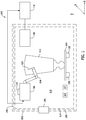
- FIG. 1 is a schematic view of an exemplary automated welding system 100.
- Automated welding system 100 includes a structure 102, a mounting platform 104, a welding tool 106, an imaging device 108, and a controller 110.
- Structure 102 is a container, such as a welding box, within which an object 112, such as an airfoil, is placed, and within which object 112 is welded.
- object 112 may include an area to be welded 126, such as a crack, and object 112 may be placed within structure 102, such that area to be welded 126 may be welded by automated welding system 100.
- structure 102 includes an internal surface 114 that defines a welding compartment 116.
- Structure 102 may be insulated by way of one or more insulating materials 101 and/or one or more shielding media 109 and may, in addition, include one or more heating apparatuses 103, such as, but not limited to, one or more electrical heating apparatuses, one or more gas burners, and the like.
- heating apparatuses 103 may be configured to raise an internal temperature of structure 102 (within welding compartment 116) to a desired temperature, such as a temperature at which object 112 becomes ductile, malleable, semi-molten, or otherwise workable.
- heating apparatuses 103 may be configured to maintain an internal temperature of structure 102 within a desired or predefined temperature range, such as a temperature range within which object 112 becomes ductile, malleable, semi-molten, or otherwise workable.
- Structure 102 may also include a viewing window 105 and/or one or more temperature sensors 107.
- Structure 102 may also be filled with an inert gas such as argon or helium. The gas may be selected to be compatible with the material of object 112.
- Mounting platform 104 is a support and mounting structure. In the exemplary embodiment, object 112 is secured or mounted on mounting platform 104 for welding operations. Mounting platform 104 may include one or more clamps or fasteners for mounting and securing object 112. Mounting platform 104 may also include one or more electromechanical actuators 118 and/or one or more joints 120, which may facilitate motion of mounting platform 104. For example, mounting platform 104 may be configured to rotate about the x, y, and/or z axes. Mounting platform 104 may also be configured to translate along the x, y, and/or z axes.
- Welding tool 106 is any tool capable of making a weld, such as, for example, a laser welding tool, an arc welding tool, a gas welding tool, a gas metal arc welding tool, and the like.
- Welding tool 106 may also include one or more electromechanical actuators 122 and/or one or more joints 124, which may facilitate motion of welding tool 106.
- each joint 124 of welding tool 106 may be rotatable about the x, y, and/or z axes.
- Welding tool 106 may also be configured to translate along the x, y, and/or z axes.
- Imaging device 108 is configured to acquire data associated with object 112, such as one or more images and/or other data of object 112.
- imaging device 108 is a camera, such as a digital or CCD camera.
- Imaging device 108 is mounted within structure 102 and is disposed relative to object 112 at a position and angle suitable to acquire one or more images of object 112.
- imaging device 108 is positioned outside of structure 102 in a position from which object 112 is viewable by imaging device 108.
- imaging device 108 may, in some embodiments, be positioned outside of structure 102, such that imaging device 108 looks through viewing window 105.
- Controller 110 coordinates the acquisition of data, such as one or more images, of object 112.
- controller 110 includes one or more processors communicatively coupled to one or more tangible, non-transitory, memories.
- controller 110 further coordinates the motion of mounting platform 104 and/or the motion of welding tool 106. Controller 110 may also coordinate the operation of welding tool 106.
- Controller 110 acquires data about object 112 and creates a path for object 112. After controller 110 has identified at least one area to be welded 126 in at least one acquired image 304 (shown in FIG. 3 ), controller 110 generates one or more control instructions for controlling one or both of mounting platform 104 and/or welding tool 106. For example, the one or more control instructions may control a position and/or an orientation of mounting platform 104 and/or welding tool 106. The control instructions may be transmitted to mounting platform 104 and/or welding tool 106 for implementation.
- FIG. 2 is a flowchart illustrating an exemplary process 200 for repairing object 112 using automated welding system 100 (shown in FIG. 1 ).
- object 112 is placed within structure 102 for repair.
- object 112 is manually or robotically mounted on mounting platform 104 within structure 102.
- master model or historical data associated with object 112 is stored for retrieval by controller 110 (step 202)
- imaging device 108 acquires data of object 112, such as one or more images of object 112 (step 204).
- object data may refer to one or more images of object 112 acquired by imaging device 108 of object 112 and/or any other data associated with object 112 that is acquired by imaging device 108, such as, for example, one or more infrared images of object 112.
- imaging device 108 may include one or more "acquired images.”
- imaging device 108 scans or photographs object 112 to acquire at least one image of object 112.
- imaging device 108 acquires a plurality of images of object 112.
- object 112 is rotated and/or translated on mounting platform through one or more inspection positions.
- imaging device 108 acquires a plurality of images of object 112 at each inspection position.
- the images may be of different portions of object 112 and may be collated or collected into an image data file.
- controller 110 receives the acquired data and compares the acquired data to stored, master model or historical data, of object 112 (step 206).
- master model data may include one or more master model images of object 112.
- Controller 110 may select a master model image that corresponds to an acquired image. For example, if a particular acquired image was taken from a particular inspection position relative to imaging device 108, a master model image taken from the same inspection position may be used for the comparison. In other embodiments, a composite image or representation formed of two or more images or data representations is used for comparison.
- controller 110 may compare each pixel in the acquired image to a corresponding pixel in the master model image, or controller 110 may compare a group of pixels in the acquired image to a group of pixels in the master model image.
- controller 110 Based upon the comparison, controller 110 identifies or determines at least one master model area in the acquired data or acquired image (step 208). For example, if a master model image includes a master model area, such as a cooling hole, controller 110 may identify or flag the pixels associated with the cooling hole in the acquired image. Controller 110 may further mask the pixels associated with the cooling hole in the acquired image, such that the pixels associated with the cooling hole are excluded from area to be welded 126 (as described below). Master model areas may also be flagged by comparison with features on a master part. However, in some embodiments, no comparison is performed. Rather, controller 110 identifies at least one area to be welded 126 based solely upon an examination or analysis of the acquired data.
- a master model image includes a master model area, such as a cooling hole
- Controller 110 may further mask the pixels associated with the cooling hole in the acquired image, such that the pixels associated with the cooling hole are excluded from area to be welded 126 (as described below). Master model areas may also be flagged by comparison with
- FIG. 3 is a schematic view of object data that may be used to identify master model areas and/or at least one area to be welded 126, as described herein.
- controller 110 may superimpose a master model image of the object over a corresponding acquired image.
- controller 110 may obtain a master model image 302 of object 112, as well as acquired data, such as an acquired image 304 of object 112.
- Controller 110 may superimpose master model image 302 over acquired image 304 (or vice versa) to generate superimposed image 306.
- Controller 110 may identify or determine one or more master model areas 308, such as a plurality of cooling holes in acquired image 304.
- master model image 302 includes a plurality of cooling holes
- the pixels associated with cooling holes will overlap with the same pixels in acquired image 304.
- These pixels in acquired image 304 maybe identified as master model areas 308 and masked, or identified as one or more masked areas, such as masked areas 312, such that they are excluded from an area to be welded in superimposed image 306 and/or in acquired image 304.
- controller 110 also compares acquired image 304 to master model image 302 to identify or determine one or more areas to be welded, such as area to be welded 126 (step 210). Area to be welded 126 may be outside of the master model areas 308 (as described above), so that controller 110 does not erroneously identify master model areas 308 as area to be welded 126 in acquired image 304.
- area to be welded 126 may be an area in which acquired image 304 differs from master model image 302 in some way. Differences between acquired image 304 and master model image 302 may occur, for example, as a result of wear on object 112 during operation.
- area to be welded 126 may correspond to a damaged or cracked area of object 112. Where object 112 is an airfoil, area to be welded 126 may also correspond to a blade tip that has been abraded or otherwise worn during service.
- controller 110 provides a control instruction or control signal to structure 102 to raise an internal temperature of structure 102 to a designated or predetermined temperature or a designated or predetermined temperature range.
- controller 110 may provide a control signal to one or more heating apparatuses 103 that cause heating apparatuses 103 to raise the internal temperature of structure 102 to a temperature at which object 112 becomes ductile, malleable, semi-molten, or otherwise workable.
- the predetermined temperature may depend upon the material composition of object 112 and may vary as different objects are provided to automated welding system 100 for inspection and repair.
- controller 110 After controller 110 has identified at least one area to be welded 126 in at least one acquired image 304, and/or in at least one superimposed image 306, controller 110 generates one or more control instructions for controlling welding operations, such as one or more control instructions for controlling one or both of mounting platform 104 and/or welding tool 106 (step 212).
- the control instructions may be transmitted to mounting platform 104 and/or welding tool 106 for implementation.
- the control instructions may be provided to one or more actuators 118 and/or joints 120.
- the control instructions may be any suitable type of control instruction, such as, for example, a computer numerical control (CNC) instruction, and the like.
- the control instructions are control signals that are provided to control platform 104 and/or welding tool 106.
- the control instructions may specify a welding path, which may be defined with reference to one or more x, y, and/or z coordinates.
- Mounting platform 104 and/or welding tool 106 may rotate and/or translate, based upon the specified welding path, such that object 112 is positioned relative to welding tool 106 in a manner that facilitates welding by welding tool 106 of area to be welded 126 on object 112.
- controller 110 guides mounting platform 104 and/or welding tool 106 along the welding path, such that area to be welded 126 is automatically welded by welding tool 106 along the welding path.
- Embodiments of the automated welding system facilitate an automated welding process in which an object is inspected to identify areas to be welded, heated to a workable temperature, and repaired by way of an automated welding process.
- a controller receives acquired data, such as one or more acquired images of an object mounted on a mounting platform within a structure, and compares the acquired data to master model data, such as at least one master model image of the object.
- the controller identifies one or more areas to be welded based upon the comparison and generates control instructions.
- One or more master model areas e.g., cooling holes
- the object is heated within the structure, and the welding tool is operated, by the controller and based upon the control instructions, to repair the object.
- Exemplary technical effects of the automated welding system described herein include, for example: (a) inspection of an object at a plurality of inspection positions; (b) identification of master model areas for exclusion from welding operations; (c) identification of areas to be welded (e.g., cracks) for welding; and (d) heating of the object to a temperature or temperature range at which the object is workable.
- Exemplary embodiments of an automated welding system and related components are described above in detail.
- the system is not limited to the specific embodiments described herein, but rather, components of systems and/or steps of the methods may be utilized independently and separately from other components and/or steps described herein.
- the configuration of components described herein may also be used in combination with other processes, and is not limited to practice with the systems and related methods as described herein. Rather, the exemplary embodiment can be implemented and utilized in connection with many applications where automated welding is desired.
- PARTS LIST automated welding system 100 insulating materials 101 Structure 102 heating apparatuses 103 Mounting platform 104 viewing window 105 welding tool 106 temperature sensors 107 imaging device 108 shielding media 109 controller 110 object 112 internal surface 114 welding compartment 116 electromechanical actuators 118 joints 120 electromechanical actuators 122 joints 124 area to be welded 126 master model image 302 acquired image 304 superimposed image 306 master model areas 308 masked areas 312
Landscapes
- Engineering & Computer Science (AREA)
- Mechanical Engineering (AREA)
- Physics & Mathematics (AREA)
- Plasma & Fusion (AREA)
- Optics & Photonics (AREA)
- Manufacturing & Machinery (AREA)
- General Engineering & Computer Science (AREA)
- Automation & Control Theory (AREA)
- General Physics & Mathematics (AREA)
- Theoretical Computer Science (AREA)
- Quality & Reliability (AREA)
- Human Computer Interaction (AREA)
- Pressure Welding/Diffusion-Bonding (AREA)
- Automatic Assembly (AREA)
- Arc Welding Control (AREA)
- Manipulator (AREA)
Abstract
Description
- The subject matter disclosed herein relates generally to an automated welding system and, more particularly, to an automated welding system that takes data of an object, such as one or more images of the object, to generate control instructions for welding the object.
- At least some known welding systems are configured to use a welding tool, such as an arc welding tool, to weld an object. In some of these systems, the object is an airfoil, which is selected for repair after the airfoil has been in operation within an aircraft engine for some amount of time. During operation, the airfoil may sustain wear, which may adversely affect its performance. For example, cracks or blade tip abrasion may occur in the airfoil, which may affect the cooling circuits of the blade and/or the aerodynamic performance. A welding tool may be used to repair these cracks and to rebuild the blade tip.
- Many known welding systems, particularly airfoil welding systems, are not fully automated. Such systems may produce an excess of process scrap and are frequently inefficient, because welders must be trained and re-trained on the welding equipment.
- In one aspect, an automated welding system is provided. The automated welding system includes a mounting platform, a welding tool, an imaging device configured to acquire data associated with an object, and a controller. The controller is configured to receive the acquired data, determine an area to be welded in the acquired data, retrieve stored master model data associated with the object, and compare the acquired data to the stored master model data to identify a master model area in the acquired data. The controller is also configured to mask the master model area in the acquired data, such that the master model area is excluded from the area to be welded, and generate control instructions for controlling at least one of the mounting platform and the welding tool to weld the area to be welded.
- The controller may also be configured to generate control instructions for controlling at least one of a position and an orientation of at least one of the mounting platform and the welding tool. In addition, the controller may be configured to analyze at least one image pixel in the acquired data to determine the area to be welded. Further, in some embodiments, the controller may be configured to superimpose the master model data of the object over the acquired data of the object such that the master model area is excluded from the area to be welded. Further still, in some embodiments, the automated welding system may include a structure configured to receive and secure the object, where the structure includes at least one of a heating apparatus, an insulating material, a shielding medium, a viewing window, a temperature sensor, and a lighting system. In addition, the controller may be configured to generate a control instruction for controlling a heating apparatus, which may be operable to control an internal temperature of the structure. In some embodiments, the control instruction for controlling the internal temperature of the structure may include an instruction to maintain the internal temperature of the structure at a predetermined temperature range.
- In another aspect, an article of manufacture is provided. The article includes a non-transitory, tangible, computer readable storage medium having instructions stored thereon that, in response to execution by a controller, cause the controller to perform operations including receiving the acquired data, determining an area to be welded in the acquired data, retrieving stored master model data associated with the object, and comparing the acquired data to the stored master model data to identify a master model area in the acquired data. The controller is also configured to perform operations including masking the master model area in the acquired data, such that the master model area is excluded from the area to be welded, and generating control instructions for controlling at least one of the mounting platform and the welding tool to weld the area to be welded.
- In some embodiments, the article may also include a structure configured to receive the object, and the controller may perform operations including generating a control instruction for controlling a heating apparatus, which is operable to control an internal temperature of the structure. In some embodiments, the control instruction for controlling the heating apparatus of the structure may be an instruction to maintain the internal temperature of the structure at a predetermined temperature range. In addition, in some embodiments, the controller may perform operations including generating control instructions for controlling at least one of a position and an orientation of at least one of the mounting platform and the welding tool. The controller may also perform operations including superimposing the stored master model data over the acquired data, such that the master model area is excluded from the area to be welded. In some embodiments, the article may include a mounting platform for mounting the object, where the mounting platform includes at least one joint that facilitates motion of the mounting platform.
- In yet another aspect, a method for operating a welding system is provided. The method includes receiving the acquired data, determining an area to be welded in the acquired data, retrieving stored master model data associated with the object, and comparing the acquired data to the stored master model data to identify a master model area in the acquired data. The controller is also configured to perform operations including masking the master model area in the acquired data, such that the master model area is excluded from the area to be welded, and generating control instructions for controlling at least one of the mounting platform and the welding tool to weld the area to be welded..
- The method may also include generating control instructions for controlling at least one of a position and an orientation of at least one of the mounting platform and the welding tool. In some embodiments, the method may include receiving the object within a structure, and generating, by the controller, a control instruction for controlling a heating apparatus operable to control an internal temperature of the structure. In addition, the method may include superimposing, by the controller, the stored master model data over the acquired data, such that the master model area is excluded from the area to be welded.
- These and other features, aspects, and advantages of the present disclosure will become better understood when the following detailed description is read with reference to the accompanying drawings in which like characters represent like parts throughout the drawings, wherein:
-
FIG. 1 is a schematic view of an exemplary automated welding system; -
FIG. 2 is a flowchart illustrating an exemplary process for repairing an object using the automated welding system shown inFIG. 1 ; and -
FIG. 3 is a schematic view of an exemplary master model image of an object, an exemplary acquired image of the object, and an exemplary superimposed image of the object that is used for welding the object within the automated welding system shown inFIG. 1 . - Unless otherwise indicated, the drawings provided herein are meant to illustrate features of embodiments of the disclosure. These features are believed to be applicable in a wide variety of systems comprising one or more embodiments of the disclosure. As such, the drawings are not meant to include all conventional features known by those of ordinary skill in the art to be required for the practice of the embodiments disclosed herein.
- In the following specification and the claims, reference will be made to a number of terms, which shall be defined to have the following meanings.
- The singular forms "a", "an", and "the" include plural references unless the context clearly dictates otherwise.
- "Optional" or "optionally" means that the subsequently described event or circumstance may or may not occur, and that the description includes instances where the event occurs and instances where it does not.
- Approximating language, as used herein throughout the specification and claims, may be applied to modify any quantitative representation that could permissibly vary without resulting in a change in the basic function to which it is related. Accordingly, a value modified by a term or terms, such as "about" and "substantially", are not to be limited to the precise value specified. In at least some instances, the approximating language may correspond to the precision of an instrument for measuring the value. Here and throughout the specification and claims, range limitations may be combined and/or interchanged, such ranges are identified and include all the sub-ranges contained therein unless context or language indicates otherwise.
- As used herein, the terms "processor" and "computer" and related terms, e.g., "processing device" and "computing device", are not limited to just those integrated circuits referred to in the art as a computer, but broadly refers to a microcontroller, a microcomputer, a programmable logic controller (PLC), an application specific integrated circuit, and other programmable circuits, and these terms are used interchangeably herein. In the embodiments described herein, memory includes, but is not limited to, a computer-readable medium, such as a random access memory (RAM), and a computer-readable non-volatile medium, such as flash memory. Alternatively, a floppy disk, a compact disc - read only memory (CD-ROM), a magneto-optical disk (MOD), and/or a digital versatile disc (DVD) may also be used. Also, in the embodiments described herein, additional input channels may be, but are not limited to, computer peripherals associated with a user interface such as a mouse and a keyboard. Alternatively, other computer peripherals may also be used that may include, for example, but not be limited to, a scanner. Furthermore, in the exemplary embodiment, additional output channels may include, but not be limited to, a user interface monitor.
- Further, as used herein, the terms "software" and "firmware" are interchangeable, and include any computer program stored in memory for execution by personal computers, workstations, clients and servers.
- As used herein, the terms "master model" and "master part" are interchangeable, and include any data used to represent the desired configuration of an
object 112. - As used herein, the term "non-transitory computer-readable media" is intended to be representative of any tangible computer-based device implemented in any method or technology for short-term and long-term storage of information, such as, computer-readable instructions, data structures, program modules and sub-modules, or other data in any device. Therefore, the methods described herein may be encoded as executable instructions embodied in a tangible, non-transitory, computer readable medium, including, without limitation, a storage device and/or a memory device. Such instructions, when executed by a processor, cause the processor to perform at least a portion of the methods described herein. Moreover, as used herein, the term "non-transitory computer-readable media" includes all tangible, computer-readable media, including, without limitation, non-transitory computer storage devices, including, without limitation, volatile and nonvolatile media, and removable and non-removable media such as a firmware, physical and virtual storage, CD-ROMs, DVDs, and any other digital source such as a network or the Internet, as well as yet to be developed digital means, with the sole exception being a transitory, propagating signal.
- Embodiments of the present disclosure relate to an automated welding system. The system generally includes a structure, such as a welding box, a welding tool, an imaging device, a controller, and a mounting platform. In operation, an object, such as an airfoil, is secured on the mounting platform and placed within the structure. The object is rotated and/or translated on the mounting platform through one or more inspection positions. At each inspection position, the imaging device acquires data, such as image data, for the object and transmits the acquired data to the controller.
- The controller receives the acquired data and compares the acquired data to master model data of the object. In various embodiments, the master model data includes one or more images and electronic data representative of the object. The controller identifies one or more areas to be welded based upon the comparison and generates control instructions. One or more standard object features (e.g., cooling holes) are masked by the controller, so that these features are not identified as areas to be welded. Finally, the object is heated within the structure, and the welding tool is operated, by the controller and based upon the control instructions, to repair the object. The images may also be acquired and compared after heating. Further, in some embodiments, no comparison is performed. Rather, the controller identifies one or more areas to be welded based solely upon an examination of the acquired data.
- As used herein, an object, such as an airfoil, may be associated with "master model" data, such as master model data and/or one or more master model images of the object. Master model data and images may be stored individually and/or as part of a data file. A master model image is an image of the object taken prior to installation of the object in an operational system. For example, where the object is an airfoil, a master model image of the airfoil is the nominal dimensional definition of the airfoil taken prior to installation of the airfoil in an aircraft engine. A master model is the engineering definition of the zero-defect nominal part. Master model data may also include historical data, which may include one or more master model object images, one or more electronic models associated with an object, coordinate points associated with an object, dimensional data, and the like. Master model data may be collected during previous maintenance of an object, such as, for example, during an overhaul of the object and/or during an overhaul of a system within which the object is configured to operate. In various embodiments, master model data may also include one or more electronic representations of an object, one or more textual descriptions of an object, one or more coordinate system points defining a shape of an object, and the like.
- In addition, although the systems, methods, and articles of manufacture are described herein with reference to an object such as an airfoil, other objects, such as marine propeller blades, components of terrestrial vehicles, and/or any other object which may be welded as part of a repair or manufacturing process, are contemplated by and within the scope of the present disclosure.
-
FIG. 1 is a schematic view of an exemplaryautomated welding system 100.Automated welding system 100 includes astructure 102, a mountingplatform 104, awelding tool 106, animaging device 108, and acontroller 110. -
Structure 102 is a container, such as a welding box, within which anobject 112, such as an airfoil, is placed, and within which object 112 is welded. As shown, object 112 may include an area to be welded 126, such as a crack, and object 112 may be placed withinstructure 102, such that area to be welded 126 may be welded byautomated welding system 100. - In the exemplary embodiment,
structure 102 includes aninternal surface 114 that defines awelding compartment 116.Structure 102 may be insulated by way of one or moreinsulating materials 101 and/or one or more shieldingmedia 109 and may, in addition, include one ormore heating apparatuses 103, such as, but not limited to, one or more electrical heating apparatuses, one or more gas burners, and the like. As described below,heating apparatuses 103 may be configured to raise an internal temperature of structure 102 (within welding compartment 116) to a desired temperature, such as a temperature at which object 112 becomes ductile, malleable, semi-molten, or otherwise workable. In addition,heating apparatuses 103 may be configured to maintain an internal temperature ofstructure 102 within a desired or predefined temperature range, such as a temperature range within which object 112 becomes ductile, malleable, semi-molten, or otherwise workable.Structure 102 may also include aviewing window 105 and/or one ormore temperature sensors 107.Structure 102 may also be filled with an inert gas such as argon or helium. The gas may be selected to be compatible with the material ofobject 112. - Mounting
platform 104 is a support and mounting structure. In the exemplary embodiment,object 112 is secured or mounted on mountingplatform 104 for welding operations. Mountingplatform 104 may include one or more clamps or fasteners for mounting and securingobject 112. Mountingplatform 104 may also include one or moreelectromechanical actuators 118 and/or one ormore joints 120, which may facilitate motion of mountingplatform 104. For example, mountingplatform 104 may be configured to rotate about the x, y, and/or z axes. Mountingplatform 104 may also be configured to translate along the x, y, and/or z axes. -
Welding tool 106 is any tool capable of making a weld, such as, for example, a laser welding tool, an arc welding tool, a gas welding tool, a gas metal arc welding tool, and the like.Welding tool 106 may also include one or moreelectromechanical actuators 122 and/or one ormore joints 124, which may facilitate motion ofwelding tool 106. For example, each joint 124 ofwelding tool 106 may be rotatable about the x, y, and/or z axes.Welding tool 106 may also be configured to translate along the x, y, and/or z axes. -
Imaging device 108 is configured to acquire data associated withobject 112, such as one or more images and/or other data ofobject 112. For example,imaging device 108 is a camera, such as a digital or CCD camera.Imaging device 108 is mounted withinstructure 102 and is disposed relative to object 112 at a position and angle suitable to acquire one or more images ofobject 112. In other embodiments,imaging device 108 is positioned outside ofstructure 102 in a position from which object 112 is viewable byimaging device 108. For example,imaging device 108 may, in some embodiments, be positioned outside ofstructure 102, such thatimaging device 108 looks throughviewing window 105. -
Controller 110 coordinates the acquisition of data, such as one or more images, ofobject 112. In the exemplary embodiment,controller 110 includes one or more processors communicatively coupled to one or more tangible, non-transitory, memories. In some embodiments,controller 110 further coordinates the motion of mountingplatform 104 and/or the motion ofwelding tool 106.Controller 110 may also coordinate the operation ofwelding tool 106. -
Controller 110 acquires data aboutobject 112 and creates a path forobject 112. Aftercontroller 110 has identified at least one area to be welded 126 in at least one acquired image 304 (shown inFIG. 3 ),controller 110 generates one or more control instructions for controlling one or both of mountingplatform 104 and/orwelding tool 106. For example, the one or more control instructions may control a position and/or an orientation of mountingplatform 104 and/orwelding tool 106. The control instructions may be transmitted to mountingplatform 104 and/orwelding tool 106 for implementation. -
FIG. 2 is a flowchart illustrating anexemplary process 200 for repairingobject 112 using automated welding system 100 (shown inFIG. 1 ). With reference toFIGs. 1 and2 , in the exemplary embodiment,object 112 is placed withinstructure 102 for repair. For example, object 112 is manually or robotically mounted on mountingplatform 104 withinstructure 102. Initially, master model or historical data associated withobject 112 is stored for retrieval by controller 110 (step 202) - Inside
structure 102,imaging device 108 acquires data ofobject 112, such as one or more images of object 112 (step 204). As used herein, "acquired data" may refer to one or more images ofobject 112 acquired byimaging device 108 ofobject 112 and/or any other data associated withobject 112 that is acquired byimaging device 108, such as, for example, one or more infrared images ofobject 112. In addition, "acquired data" may include one or more "acquired images." For example,imaging device 108 scans or photographs object 112 to acquire at least one image ofobject 112. In the exemplary embodiment,imaging device 108 acquires a plurality of images ofobject 112. For example, object 112 is rotated and/or translated on mounting platform through one or more inspection positions. Asobject 112 is moved,imaging device 108 acquires a plurality of images ofobject 112 at each inspection position. The images may be of different portions ofobject 112 and may be collated or collected into an image data file. - The acquired data is transmitted by
imaging device 108 tocontroller 110.Controller 110 receives the acquired data and compares the acquired data to stored, master model or historical data, of object 112 (step 206). As used herein, and as described above, "master model data" may include one or more master model images ofobject 112.Controller 110 may select a master model image that corresponds to an acquired image. For example, if a particular acquired image was taken from a particular inspection position relative toimaging device 108, a master model image taken from the same inspection position may be used for the comparison. In other embodiments, a composite image or representation formed of two or more images or data representations is used for comparison. To compare an acquired image to a master model image,controller 110 may compare each pixel in the acquired image to a corresponding pixel in the master model image, orcontroller 110 may compare a group of pixels in the acquired image to a group of pixels in the master model image. - Based upon the comparison,
controller 110 identifies or determines at least one master model area in the acquired data or acquired image (step 208). For example, if a master model image includes a master model area, such as a cooling hole,controller 110 may identify or flag the pixels associated with the cooling hole in the acquired image.Controller 110 may further mask the pixels associated with the cooling hole in the acquired image, such that the pixels associated with the cooling hole are excluded from area to be welded 126 (as described below). Master model areas may also be flagged by comparison with features on a master part. However, in some embodiments, no comparison is performed. Rather,controller 110 identifies at least one area to be welded 126 based solely upon an examination or analysis of the acquired data. -
FIG. 3 is a schematic view of object data that may be used to identify master model areas and/or at least one area to be welded 126, as described herein. Accordingly, with reference toFIGs. 1-3 , and in some embodiments,controller 110 may superimpose a master model image of the object over a corresponding acquired image. For example, and as described above,controller 110 may obtain amaster model image 302 ofobject 112, as well as acquired data, such as an acquiredimage 304 ofobject 112.Controller 110 may superimposemaster model image 302 over acquired image 304 (or vice versa) to generatesuperimposed image 306.Controller 110 may identify or determine one or moremaster model areas 308, such as a plurality of cooling holes in acquiredimage 304. For example, ifmaster model image 302 includes a plurality of cooling holes, the pixels associated with cooling holes will overlap with the same pixels in acquiredimage 304. These pixels in acquiredimage 304 maybe identified asmaster model areas 308 and masked, or identified as one or more masked areas, such asmasked areas 312, such that they are excluded from an area to be welded insuperimposed image 306 and/or in acquiredimage 304. - In
exemplary process 200,controller 110 also compares acquiredimage 304 tomaster model image 302 to identify or determine one or more areas to be welded, such as area to be welded 126 (step 210). Area to be welded 126 may be outside of the master model areas 308 (as described above), so thatcontroller 110 does not erroneously identifymaster model areas 308 as area to be welded 126 in acquiredimage 304. - In the exemplary embodiment, area to be welded 126 may be an area in which acquired
image 304 differs frommaster model image 302 in some way. Differences between acquiredimage 304 andmaster model image 302 may occur, for example, as a result of wear onobject 112 during operation. For example, area to be welded 126 may correspond to a damaged or cracked area ofobject 112. Whereobject 112 is an airfoil, area to be welded 126 may also correspond to a blade tip that has been abraded or otherwise worn during service. - In some embodiments,
controller 110 provides a control instruction or control signal to structure 102 to raise an internal temperature ofstructure 102 to a designated or predetermined temperature or a designated or predetermined temperature range. For example,controller 110 may provide a control signal to one ormore heating apparatuses 103 that causeheating apparatuses 103 to raise the internal temperature ofstructure 102 to a temperature at which object 112 becomes ductile, malleable, semi-molten, or otherwise workable. Thus, the predetermined temperature may depend upon the material composition ofobject 112 and may vary as different objects are provided toautomated welding system 100 for inspection and repair. - In
exemplary process 200, aftercontroller 110 has identified at least one area to be welded 126 in at least one acquiredimage 304, and/or in at least onesuperimposed image 306,controller 110 generates one or more control instructions for controlling welding operations, such as one or more control instructions for controlling one or both of mountingplatform 104 and/or welding tool 106 (step 212). The control instructions may be transmitted to mountingplatform 104 and/orwelding tool 106 for implementation. For example, the control instructions may be provided to one ormore actuators 118 and/or joints 120. The control instructions may be any suitable type of control instruction, such as, for example, a computer numerical control (CNC) instruction, and the like. In some embodiments, the control instructions are control signals that are provided to controlplatform 104 and/orwelding tool 106. - The control instructions may specify a welding path, which may be defined with reference to one or more x, y, and/or z coordinates. Mounting
platform 104 and/orwelding tool 106 may rotate and/or translate, based upon the specified welding path, such thatobject 112 is positioned relative towelding tool 106 in a manner that facilitates welding by weldingtool 106 of area to be welded 126 onobject 112. Thus,controller 110guides mounting platform 104 and/orwelding tool 106 along the welding path, such that area to be welded 126 is automatically welded by weldingtool 106 along the welding path. - Embodiments of the automated welding system, as described above, facilitate an automated welding process in which an object is inspected to identify areas to be welded, heated to a workable temperature, and repaired by way of an automated welding process. Accordingly, a controller receives acquired data, such as one or more acquired images of an object mounted on a mounting platform within a structure, and compares the acquired data to master model data, such as at least one master model image of the object. The controller identifies one or more areas to be welded based upon the comparison and generates control instructions. One or more master model areas (e.g., cooling holes) are masked by the controller, so that these master model areas are not identified as areas to be welded. Finally, the object is heated within the structure, and the welding tool is operated, by the controller and based upon the control instructions, to repair the object.
- Exemplary technical effects of the automated welding system described herein include, for example: (a) inspection of an object at a plurality of inspection positions; (b) identification of master model areas for exclusion from welding operations; (c) identification of areas to be welded (e.g., cracks) for welding; and (d) heating of the object to a temperature or temperature range at which the object is workable.
- Exemplary embodiments of an automated welding system and related components are described above in detail. The system is not limited to the specific embodiments described herein, but rather, components of systems and/or steps of the methods may be utilized independently and separately from other components and/or steps described herein. For example, the configuration of components described herein may also be used in combination with other processes, and is not limited to practice with the systems and related methods as described herein. Rather, the exemplary embodiment can be implemented and utilized in connection with many applications where automated welding is desired.
- Although specific features of various embodiments of the present disclosure may be shown in some drawings and not in others, this is for convenience only. In accordance with the principles of the present disclosure, any feature of a drawing may be referenced and/or claimed in combination with any feature of any other drawing.
- This written description uses examples to disclose the embodiments of the present disclosure, including the best mode, and also to enable any person skilled in the art to practice the disclosure, including making and using any devices or systems and performing any incorporated methods. The patentable scope of the embodiments described herein is defined by the claims, and may include other examples that occur to those skilled in the art. Such other examples are intended to be within the scope of the claims if they have structural elements that do not differ from the literal language of the claims, or if they include equivalent structural elements with insubstantial differences from the literal language of the claims.
- Various aspects and embodiments of the present invention are disclosed in the following numbered clauses. Any features of any of the aspects and/or embodiments may be readily combined with one or more features of any other aspect or embodiment described herein.
- 1. An automated welding system comprising:
- a mounting platform;
- a welding tool;
- an imaging device configured to acquire data associated with an object; and
- a controller configured to:
- receive the acquired data;
- determine an area to be welded in the acquired data;
- retrieve stored master model data associated with the object;
- compare the acquired data to the stored master model data to identify a master model area in the acquired data;
- mask the master model area in the acquired data, such that the master model area is excluded from the area to be welded; and
- generate control instructions for controlling at least one of said mounting platform and said welding tool to weld the area to be welded.
- 2. The automated welding system of Clause 1, wherein said controller is further configured to generate control instructions for controlling at least one of a position and an orientation of at least one of said mounting platform and said welding tool.
- 3. The automated welding system of Clause 1 or 2, wherein said controller is further configured to analyze at least one image pixel in the acquired data to determine the area to be welded.
- 4. The automated welding system of any preceding Clause, wherein said controller is further configured to superimpose the master model data of the object over the acquired data of the object such that the master model area is excluded from the area to be welded.
- 5. The automated welding system of any preceding Clause, further comprising a structure configured to receive and secure the object, the structure comprising at least one of a heating apparatus, an insulating material, a shielding medium, a viewing window, a temperature sensor, and a lighting system.
- 6. The automated welding system of Clause 5, wherein said controller is further configured to generate a control instruction for controlling a heating apparatus operable to control an internal temperature of said structure.
- 7. The automated welding system of Clause 6, wherein the control instruction for controlling the internal temperature of said structure comprises an instruction to maintain the internal temperature of said structure at a predetermined temperature range.
- 8. The automated welding system of any preceding Clause, wherein said mounting platform includes at least one joint that facilitates motion of said mounting platform.
- 9. An article of manufacture including a non-transitory, tangible, computer readable storage medium having instructions stored thereon that, in response to execution by a controller configured for providing control instructions to at least one of a mounting platform and a welding tool, cause said controller to perform operations comprising:
- receiving, by said controller, acquired data of an object;
- determining, by said controller, an area to be welded in the acquired data;
- retrieving by said controller, stored master model data associated with the object;
comparing by said controller, the acquired data to the stored master model data to identify a master model area in the acquired data; - masking, by said controller, the master model area in the acquired data, such that the master model area is excluded from the area to be welded; and
- generating, by said controller, control instructions for controlling at least one of said mounting platform and said welding tool to weld the area to be welded.
- 10. The article of Clause 9, further comprising a structure configured to receive the object and permit welding operations to be conducted on the object at a predetermined temperature range.
- 11. The article of Clause 9 or 10, wherein the instructions further cause said controller to perform operations comprising generating, by said controller, a control instruction for controlling a heating apparatus operable to control an internal temperature of said structure.
- 12. The article of any of Clauses 9 to 11, wherein the control instruction for controlling the heating apparatus of said structure is an instruction to maintain the internal temperature of said structure within a predetermined temperature range.
- 13. The article of any of Clauses 9 to 12, wherein the instructions further cause said controller to perform operations comprising generating control instructions for controlling at least one of a position and an orientation of at least one of said mounting platform and said welding tool.
- 14. The article of any of Clauses 9 to 13, wherein the instructions further cause said controller to perform operations comprising superimposing, by said controller, the stored master model data over the acquired data, such that the master model area is excluded from the area to be welded.
- 15. The article of any of Clauses 9 to 14, further comprising a mounting platform for mounting the object, wherein said mounting platform includes at least one joint that facilitates motion of said mounting platform.
- 16. A method for operating a welding system, said method comprising:
- receiving, by a controller configured to control operation of the welding system, acquired data of an object;
- determining, by said controller, an area to be welded in the acquired data;
- retrieving by said controller, stored master model data associated with the object;
- comparing by said controller, the acquired data to the stored master model data to identify a master model area in the acquired data;
generating, by said controller, control instructions for controlling at least one of said mounting platform and said welding tool to weld the area to be welded. - 17. The method of Clause 16, further comprising generating, by said controller, control instructions for controlling at least one of a position and an orientation of at least one of said mounting platform and said welding tool.
- 18. The method of Clause 16 or 17, further comprising receiving the object within a structure.
- 19. The method of any of Clauses 16 to 18, further comprising generating, by the controller, a control instruction for controlling a heating apparatus operable to control an internal temperature of the structure.
- 20. The method of any of Clauses 16 to 19, wherein the masking includes superimposing, by said controller, the stored master model data over the acquired data, such that the master model area is excluded from the area to be welded.
-
PARTS LIST automated welding system 100 insulating materials 101 Structure 102 heating apparatuses 103 Mounting platform 104 viewing window 105 welding tool 106 temperature sensors 107 imaging device 108 shielding media 109 controller 110 object 112 internal surface 114 welding compartment 116 electromechanical actuators 118 joints 120 electromechanical actuators 122 joints 124 area to be welded 126 master model image 302 acquired image 304 superimposed image 306 master model areas 308 masked areas 312
Claims (15)
- An automated welding system (100) comprising:a mounting platform (104);a welding tool (106);an imaging device (108) configured to acquire data associated with an object (112); anda controller (110) configured to:receive the acquired data;determine an area to be welded (126) in the acquired data;retrieve stored master model data associated with the object (112);compare the acquired data to the stored master model data to identify a master model area (308) in the acquired data;mask the master model area (308) in the acquired data, such that the master model area (308) is excluded from the area to be welded (126); andgenerate control instructions for controlling at least one of said mounting platform (104) and said welding tool (106) to weld the area to be welded (126).
- The automated welding system (100) of Claim 1, wherein said controller (110) is further configured to generate control instructions for controlling at least one of a position and an orientation of at least one of said mounting platform (104) and said welding tool (106).
- The automated welding system (100) of Claim 1 or 2, wherein said controller (110) is further configured to analyze at least one image pixel in the acquired data to determine the area to be welded (126).
- The automated welding system (100) of any preceding Claim, wherein said controller (110) is further configured to superimpose the master model data of the object (112) over the acquired data of the object (112) such that the master model area (308) is excluded from the area to be welded (126).
- The automated welding system (100) of any preceding Claim, further comprising a structure (102) configured to receive and secure the object (112), the structure (102) comprising at least one of a heating apparatus (103), an insulating material (101), a shielding medium (109), a viewing window (105), and a temperature sensor (107).
- The automated welding system (100) of Claim 5, wherein said controller (110) is further configured to generate a control instruction for controlling a heating apparatus (103) operable to control an internal temperature of said structure (102).
- The automated welding system (100) of Claim 6, wherein the control instruction for controlling the internal temperature of said structure (102) comprises an instruction to maintain the internal temperature of said structure (102) at a predetermined temperature range.
- The automated welding system (100) of any preceding Claim, wherein said mounting platform (104) includes at least one joint (120) that facilitates motion of said mounting platform (104).
- An article of manufacture including a non-transitory, tangible, computer readable storage medium having instructions stored thereon that, in response to execution by a controller (110) configured for providing control instructions to at least one of a mounting platform (104) and a welding tool (106), cause said controller (110) to perform operations comprising:receiving, by said controller (110), acquired data of an object (112);determining, by said controller (110), an area to be welded (126) in the acquired data;retrieving by said controller (110), stored master model data associated with the object (112);comparing by said controller (110), the acquired data to the stored master model data to identify a master model area (308) in the acquired data;masking, by said controller (110), the master model area (308) in the acquired data, such that the master model area (308) is excluded from the area to be welded (126); andgenerating, by said controller (110), control instructions for controlling at least one of said mounting platform (104) and said welding tool (106) to weld the area to be welded (126).
- The article of Claim 9, further comprising a structure (102) configured to receive the object (112) and permit welding operations to be conducted on the object (112) at a predetermined temperature range.
- The article of Claim 10, wherein the instructions further cause said controller (110) to perform operations comprising generating, by said controller (110), a control instruction for controlling a heating apparatus (103) operable to control an internal temperature of said structure (102).
- The article of Claim 11, wherein the control instruction for controlling the heating apparatus (103) of said structure (102) is an instruction to maintain the internal temperature of said structure (102) within a predetermined temperature range.
- The article of any of Claims 9 to 12, wherein the instructions further cause said controller (110) to perform operations comprising generating control instructions for controlling at least one of a position and an orientation of at least one of said mounting platform (104) and said welding tool (106).
- The article of any of Claims 9 to 13, wherein the instructions further cause said controller (110) to perform operations comprising superimposing, by said controller (110), the stored master model data over the acquired data, such that the master model area (308) is excluded from the area to be welded (126).
- A method for operating a welding system (100), said method comprising:receiving, by a controller (110) configured to control operation of the welding system (100), acquired data of an object (112);determining, by said controller (110), an area to be welded (126) in the acquired data;retrieving by said controller (110), stored master model data associated with the object (112);comparing by said controller (110), the acquired data to the stored master model data to identify a master model area (308) in the acquired data;masking, by said controller (110), the master model area (308) in the acquired data, such that the master model area (308) is excluded from the area to be welded (126); andgenerating, by said controller (110), control instructions for controlling at least one of said mounting platform (104) and said welding tool (106) to weld the area to be welded (126).
Applications Claiming Priority (1)
| Application Number | Priority Date | Filing Date | Title |
|---|---|---|---|
| US15/631,119 US10816963B2 (en) | 2017-06-23 | 2017-06-23 | Systems and methods for automated welding |
Publications (2)
| Publication Number | Publication Date |
|---|---|
| EP3417975A1 true EP3417975A1 (en) | 2018-12-26 |
| EP3417975B1 EP3417975B1 (en) | 2020-05-20 |
Family
ID=62715899
Family Applications (1)
| Application Number | Title | Priority Date | Filing Date |
|---|---|---|---|
| EP18178746.6A Active EP3417975B1 (en) | 2017-06-23 | 2018-06-20 | System and method for automated welding |
Country Status (5)
| Country | Link |
|---|---|
| US (1) | US10816963B2 (en) |
| EP (1) | EP3417975B1 (en) |
| CN (1) | CN109108430B (en) |
| CA (1) | CA3008376A1 (en) |
| SG (1) | SG10201804824QA (en) |
Cited By (1)
| Publication number | Priority date | Publication date | Assignee | Title |
|---|---|---|---|---|
| CN114502318A (en) * | 2019-10-11 | 2022-05-13 | 松下知识产权经营株式会社 | Welding method, identifier providing device, and welded article |
Families Citing this family (3)
| Publication number | Priority date | Publication date | Assignee | Title |
|---|---|---|---|---|
| US20200316729A1 (en) * | 2019-04-05 | 2020-10-08 | United Technologies Corporation | Weld repair system |
| US11371349B2 (en) | 2019-04-05 | 2022-06-28 | Raytheon Technologies Corporation | Gas impingement in-process cooling system |
| CN113231715A (en) * | 2021-05-31 | 2021-08-10 | 华南理工大学 | Ultra-low heat input fast frequency welding repair method for large blade |
Citations (2)
| Publication number | Priority date | Publication date | Assignee | Title |
|---|---|---|---|---|
| FR2897550A1 (en) * | 2006-02-23 | 2007-08-24 | Snecma Sa | PROCESS FOR REPAIRING A METAL PART USING A RECHARGING TOOL |
| WO2014042970A1 (en) * | 2012-09-12 | 2014-03-20 | Siemens Energy, Inc. | Method for automated superalloy laser cladding with 3d imaging weld path control |
Family Cites Families (15)
| Publication number | Priority date | Publication date | Assignee | Title |
|---|---|---|---|---|
| US6054672A (en) | 1998-09-15 | 2000-04-25 | Chromalloy Gas Turbine Corporation | Laser welding superalloy articles |
| CN1280058C (en) | 2001-09-22 | 2006-10-18 | 克瓦纳尔.马沙-亚德斯有限公司 | Welding device and method |
| US6912446B2 (en) | 2002-10-23 | 2005-06-28 | General Electric Company | Systems and methods for automated sensing and machining for repairing airfoils of blades |
| US7689003B2 (en) | 2006-03-20 | 2010-03-30 | Siemens Energy, Inc. | Combined 2D and 3D nondestructive examination |
| FR2911372B1 (en) | 2007-01-15 | 2009-02-27 | Aircelle Sa | TRANSLATABLE PUSH INVERTER FOR REACTION ENGINE |
| US9038367B2 (en) | 2011-09-16 | 2015-05-26 | United Technologies Corporation | Fan case thrust reverser |
| CN102350571A (en) | 2011-09-22 | 2012-02-15 | 唐山轨道客车有限责任公司 | Automatic welding guiding device and automatic welding method |
| CN102424971B (en) * | 2011-12-21 | 2013-06-26 | 西安铂力特激光成形技术有限公司 | Rapid laser repair method and device for defect of aluminum alloy guide blade |
| US20130180107A1 (en) | 2012-01-15 | 2013-07-18 | Steven Charles Woods | Method for refurbishing a turbo-machine component |
| US8962066B2 (en) | 2012-06-04 | 2015-02-24 | United Technologies Corporation | Coating for cooling air holes |
| US9289854B2 (en) | 2012-09-12 | 2016-03-22 | Siemens Energy, Inc. | Automated superalloy laser cladding with 3D imaging weld path control |
| CN102886606B (en) * | 2012-10-16 | 2015-08-26 | 江苏大学 | A kind of method and apparatus of laser remanufacturing sheet metal weldment |
| CN104416251B (en) | 2013-08-27 | 2017-04-12 | 泰科电子公司 | Automatic welding system and automatic welding method |
| US10427239B2 (en) * | 2015-04-02 | 2019-10-01 | Illinois Tool Works Inc. | Systems and methods for tracking weld training arc parameters |
| US10579746B2 (en) * | 2016-03-28 | 2020-03-03 | Jz Technologies, Llc | Method and apparatus for applying an architectural layout to a building construction surface |
-
2017
- 2017-06-23 US US15/631,119 patent/US10816963B2/en active Active
-
2018
- 2018-06-06 SG SG10201804824QA patent/SG10201804824QA/en unknown
- 2018-06-14 CA CA3008376A patent/CA3008376A1/en not_active Abandoned
- 2018-06-20 EP EP18178746.6A patent/EP3417975B1/en active Active
- 2018-06-22 CN CN201810651405.XA patent/CN109108430B/en active Active
Patent Citations (2)
| Publication number | Priority date | Publication date | Assignee | Title |
|---|---|---|---|---|
| FR2897550A1 (en) * | 2006-02-23 | 2007-08-24 | Snecma Sa | PROCESS FOR REPAIRING A METAL PART USING A RECHARGING TOOL |
| WO2014042970A1 (en) * | 2012-09-12 | 2014-03-20 | Siemens Energy, Inc. | Method for automated superalloy laser cladding with 3d imaging weld path control |
Cited By (2)
| Publication number | Priority date | Publication date | Assignee | Title |
|---|---|---|---|---|
| CN114502318A (en) * | 2019-10-11 | 2022-05-13 | 松下知识产权经营株式会社 | Welding method, identifier providing device, and welded article |
| US12594617B2 (en) | 2019-10-11 | 2026-04-07 | Panasonic Intellectual Property Management Co., Ltd. | Welding method, identification sign assignment device, and weldment |
Also Published As
| Publication number | Publication date |
|---|---|
| CA3008376A1 (en) | 2018-12-23 |
| US20180373231A1 (en) | 2018-12-27 |
| CN109108430A (en) | 2019-01-01 |
| SG10201804824QA (en) | 2019-01-30 |
| EP3417975B1 (en) | 2020-05-20 |
| US10816963B2 (en) | 2020-10-27 |
| CN109108430B (en) | 2021-10-22 |
Similar Documents
| Publication | Publication Date | Title |
|---|---|---|
| EP3417974B1 (en) | System, article and method for automated welding | |
| EP3417975B1 (en) | System and method for automated welding | |
| US20160159011A1 (en) | Vision System for Selective Tridimensional Repair Using Additive Manufacturing | |
| US9827717B2 (en) | Statistical predictive modeling and compensation of geometric deviations of 3D printed products | |
| Xu et al. | Realisation of a multi-sensor framework for process monitoring of the wire arc additive manufacturing in producing Ti-6Al-4V parts | |
| CN101322071B (en) | System and related method for projecting defects and inspecting locations | |
| US20230294221A1 (en) | Method and arrangement for repairing a workpiece | |
| EP2254728B1 (en) | System and method for repairing objects | |
| US20180193947A1 (en) | Imaging devices for use with additive manufacturing systems and methods of monitoring and inspecting additive manufacturing components | |
| US20180099333A1 (en) | Method and system for topographical based inspection and process control for additive manufactured parts | |
| US20160202691A1 (en) | Method for compensating errors occurring in a production process | |
| JP7455501B2 (en) | Dynamic modification of manufacturing plans according to manufacturing deviations | |
| US11203160B2 (en) | Adaptive multi-process additive manufacturing systems and methods | |
| CN103231162A (en) | Device and method for visual detection of welding quality of robot | |
| JP2007009908A (en) | Specifying method and specifying device for position and angular direction of single or plurality of holes | |
| US10668673B2 (en) | Systems and methods for automated composite layup quality assurance | |
| JP2015109081A (en) | System and method for operating machine and performing quality assurance | |
| EP3748446A1 (en) | Additive manufacturing systems and methods of pretreating and additively printing on workpieces | |
| Liu et al. | Stereo vision-based repair of metallic components | |
| US20160349729A1 (en) | Method for machining a component on a multi-axis machine tool driven by an nc-controller and apparatus for conducting said method | |
| CN111283342A (en) | Workpiece defect repairing method and workpiece defect repairing robot | |
| Lettori et al. | Geometrical characterization of circular multi-layered CMT WAAM specimens by 3D structured light scanning | |
| US20210187750A1 (en) | Workbench system | |
| US20210154829A1 (en) | Workbench system | |
| Liu et al. | Research progress of intelligent thermal spraying system for aeroengine blades |
Legal Events
| Date | Code | Title | Description |
|---|---|---|---|
| PUAI | Public reference made under article 153(3) epc to a published international application that has entered the european phase |
Free format text: ORIGINAL CODE: 0009012 |
|
| STAA | Information on the status of an ep patent application or granted ep patent |
Free format text: STATUS: THE APPLICATION HAS BEEN PUBLISHED |
|
| AK | Designated contracting states |
Kind code of ref document: A1 Designated state(s): AL AT BE BG CH CY CZ DE DK EE ES FI FR GB GR HR HU IE IS IT LI LT LU LV MC MK MT NL NO PL PT RO RS SE SI SK SM TR |
|
| AX | Request for extension of the european patent |
Extension state: BA ME |
|
| STAA | Information on the status of an ep patent application or granted ep patent |
Free format text: STATUS: REQUEST FOR EXAMINATION WAS MADE |
|
| 17P | Request for examination filed |
Effective date: 20190625 |
|
| RBV | Designated contracting states (corrected) |
Designated state(s): AL AT BE BG CH CY CZ DE DK EE ES FI FR GB GR HR HU IE IS IT LI LT LU LV MC MK MT NL NO PL PT RO RS SE SI SK SM TR |
|
| RIC1 | Information provided on ipc code assigned before grant |
Ipc: B23K 9/095 20060101AFI20191015BHEP Ipc: B23K 26/342 20140101ALI20191015BHEP Ipc: F01D 5/00 20060101ALI20191015BHEP Ipc: B23P 6/00 20060101ALI20191015BHEP Ipc: B23K 101/00 20060101ALN20191015BHEP Ipc: B23K 9/04 20060101ALI20191015BHEP Ipc: B23K 26/03 20060101ALI20191015BHEP |
|
| GRAP | Despatch of communication of intention to grant a patent |
Free format text: ORIGINAL CODE: EPIDOSNIGR1 |
|
| STAA | Information on the status of an ep patent application or granted ep patent |
Free format text: STATUS: GRANT OF PATENT IS INTENDED |
|
| INTG | Intention to grant announced |
Effective date: 20191126 |
|
| GRAS | Grant fee paid |
Free format text: ORIGINAL CODE: EPIDOSNIGR3 |
|
| GRAA | (expected) grant |
Free format text: ORIGINAL CODE: 0009210 |
|
| STAA | Information on the status of an ep patent application or granted ep patent |
Free format text: STATUS: THE PATENT HAS BEEN GRANTED |
|
| AK | Designated contracting states |
Kind code of ref document: B1 Designated state(s): AL AT BE BG CH CY CZ DE DK EE ES FI FR GB GR HR HU IE IS IT LI LT LU LV MC MK MT NL NO PL PT RO RS SE SI SK SM TR |
|
| REG | Reference to a national code |
Ref country code: GB Ref legal event code: FG4D |
|
| REG | Reference to a national code |
Ref country code: CH Ref legal event code: EP |
|
| REG | Reference to a national code |
Ref country code: DE Ref legal event code: R096 Ref document number: 602018004724 Country of ref document: DE |
|
| REG | Reference to a national code |
Ref country code: AT Ref legal event code: REF Ref document number: 1272290 Country of ref document: AT Kind code of ref document: T Effective date: 20200615 |
|
| REG | Reference to a national code |
Ref country code: LT Ref legal event code: MG4D |
|
| REG | Reference to a national code |
Ref country code: NL Ref legal event code: MP Effective date: 20200520 |
|
| PG25 | Lapsed in a contracting state [announced via postgrant information from national office to epo] |
Ref country code: PT Free format text: LAPSE BECAUSE OF FAILURE TO SUBMIT A TRANSLATION OF THE DESCRIPTION OR TO PAY THE FEE WITHIN THE PRESCRIBED TIME-LIMIT Effective date: 20200921 Ref country code: IS Free format text: LAPSE BECAUSE OF FAILURE TO SUBMIT A TRANSLATION OF THE DESCRIPTION OR TO PAY THE FEE WITHIN THE PRESCRIBED TIME-LIMIT Effective date: 20200920 Ref country code: SE Free format text: LAPSE BECAUSE OF FAILURE TO SUBMIT A TRANSLATION OF THE DESCRIPTION OR TO PAY THE FEE WITHIN THE PRESCRIBED TIME-LIMIT Effective date: 20200520 Ref country code: FI Free format text: LAPSE BECAUSE OF FAILURE TO SUBMIT A TRANSLATION OF THE DESCRIPTION OR TO PAY THE FEE WITHIN THE PRESCRIBED TIME-LIMIT Effective date: 20200520 Ref country code: NO Free format text: LAPSE BECAUSE OF FAILURE TO SUBMIT A TRANSLATION OF THE DESCRIPTION OR TO PAY THE FEE WITHIN THE PRESCRIBED TIME-LIMIT Effective date: 20200820 Ref country code: GR Free format text: LAPSE BECAUSE OF FAILURE TO SUBMIT A TRANSLATION OF THE DESCRIPTION OR TO PAY THE FEE WITHIN THE PRESCRIBED TIME-LIMIT Effective date: 20200821 Ref country code: LT Free format text: LAPSE BECAUSE OF FAILURE TO SUBMIT A TRANSLATION OF THE DESCRIPTION OR TO PAY THE FEE WITHIN THE PRESCRIBED TIME-LIMIT Effective date: 20200520 |
|
| PG25 | Lapsed in a contracting state [announced via postgrant information from national office to epo] |
Ref country code: BG Free format text: LAPSE BECAUSE OF FAILURE TO SUBMIT A TRANSLATION OF THE DESCRIPTION OR TO PAY THE FEE WITHIN THE PRESCRIBED TIME-LIMIT Effective date: 20200820 Ref country code: LV Free format text: LAPSE BECAUSE OF FAILURE TO SUBMIT A TRANSLATION OF THE DESCRIPTION OR TO PAY THE FEE WITHIN THE PRESCRIBED TIME-LIMIT Effective date: 20200520 Ref country code: RS Free format text: LAPSE BECAUSE OF FAILURE TO SUBMIT A TRANSLATION OF THE DESCRIPTION OR TO PAY THE FEE WITHIN THE PRESCRIBED TIME-LIMIT Effective date: 20200520 Ref country code: HR Free format text: LAPSE BECAUSE OF FAILURE TO SUBMIT A TRANSLATION OF THE DESCRIPTION OR TO PAY THE FEE WITHIN THE PRESCRIBED TIME-LIMIT Effective date: 20200520 |
|
| REG | Reference to a national code |
Ref country code: AT Ref legal event code: MK05 Ref document number: 1272290 Country of ref document: AT Kind code of ref document: T Effective date: 20200520 |
|
| PG25 | Lapsed in a contracting state [announced via postgrant information from national office to epo] |
Ref country code: AL Free format text: LAPSE BECAUSE OF FAILURE TO SUBMIT A TRANSLATION OF THE DESCRIPTION OR TO PAY THE FEE WITHIN THE PRESCRIBED TIME-LIMIT Effective date: 20200520 Ref country code: NL Free format text: LAPSE BECAUSE OF FAILURE TO SUBMIT A TRANSLATION OF THE DESCRIPTION OR TO PAY THE FEE WITHIN THE PRESCRIBED TIME-LIMIT Effective date: 20200520 |
|
| PG25 | Lapsed in a contracting state [announced via postgrant information from national office to epo] |
Ref country code: SM Free format text: LAPSE BECAUSE OF FAILURE TO SUBMIT A TRANSLATION OF THE DESCRIPTION OR TO PAY THE FEE WITHIN THE PRESCRIBED TIME-LIMIT Effective date: 20200520 Ref country code: EE Free format text: LAPSE BECAUSE OF FAILURE TO SUBMIT A TRANSLATION OF THE DESCRIPTION OR TO PAY THE FEE WITHIN THE PRESCRIBED TIME-LIMIT Effective date: 20200520 Ref country code: AT Free format text: LAPSE BECAUSE OF FAILURE TO SUBMIT A TRANSLATION OF THE DESCRIPTION OR TO PAY THE FEE WITHIN THE PRESCRIBED TIME-LIMIT Effective date: 20200520 Ref country code: DK Free format text: LAPSE BECAUSE OF FAILURE TO SUBMIT A TRANSLATION OF THE DESCRIPTION OR TO PAY THE FEE WITHIN THE PRESCRIBED TIME-LIMIT Effective date: 20200520 Ref country code: IT Free format text: LAPSE BECAUSE OF FAILURE TO SUBMIT A TRANSLATION OF THE DESCRIPTION OR TO PAY THE FEE WITHIN THE PRESCRIBED TIME-LIMIT Effective date: 20200520 Ref country code: CZ Free format text: LAPSE BECAUSE OF FAILURE TO SUBMIT A TRANSLATION OF THE DESCRIPTION OR TO PAY THE FEE WITHIN THE PRESCRIBED TIME-LIMIT Effective date: 20200520 Ref country code: RO Free format text: LAPSE BECAUSE OF FAILURE TO SUBMIT A TRANSLATION OF THE DESCRIPTION OR TO PAY THE FEE WITHIN THE PRESCRIBED TIME-LIMIT Effective date: 20200520 Ref country code: ES Free format text: LAPSE BECAUSE OF FAILURE TO SUBMIT A TRANSLATION OF THE DESCRIPTION OR TO PAY THE FEE WITHIN THE PRESCRIBED TIME-LIMIT Effective date: 20200520 |
|
| REG | Reference to a national code |
Ref country code: DE Ref legal event code: R097 Ref document number: 602018004724 Country of ref document: DE |
|
| PG25 | Lapsed in a contracting state [announced via postgrant information from national office to epo] |
Ref country code: SK Free format text: LAPSE BECAUSE OF FAILURE TO SUBMIT A TRANSLATION OF THE DESCRIPTION OR TO PAY THE FEE WITHIN THE PRESCRIBED TIME-LIMIT Effective date: 20200520 Ref country code: PL Free format text: LAPSE BECAUSE OF FAILURE TO SUBMIT A TRANSLATION OF THE DESCRIPTION OR TO PAY THE FEE WITHIN THE PRESCRIBED TIME-LIMIT Effective date: 20200520 Ref country code: MC Free format text: LAPSE BECAUSE OF FAILURE TO SUBMIT A TRANSLATION OF THE DESCRIPTION OR TO PAY THE FEE WITHIN THE PRESCRIBED TIME-LIMIT Effective date: 20200520 |
|
| PLBE | No opposition filed within time limit |
Free format text: ORIGINAL CODE: 0009261 |
|
| STAA | Information on the status of an ep patent application or granted ep patent |
Free format text: STATUS: NO OPPOSITION FILED WITHIN TIME LIMIT |
|
| PG25 | Lapsed in a contracting state [announced via postgrant information from national office to epo] |
Ref country code: LU Free format text: LAPSE BECAUSE OF NON-PAYMENT OF DUE FEES Effective date: 20200620 |
|
| REG | Reference to a national code |
Ref country code: BE Ref legal event code: MM Effective date: 20200630 |
|
| 26N | No opposition filed |
Effective date: 20210223 |
|
| PG25 | Lapsed in a contracting state [announced via postgrant information from national office to epo] |
Ref country code: IE Free format text: LAPSE BECAUSE OF NON-PAYMENT OF DUE FEES Effective date: 20200620 |
|
| PG25 | Lapsed in a contracting state [announced via postgrant information from national office to epo] |
Ref country code: BE Free format text: LAPSE BECAUSE OF NON-PAYMENT OF DUE FEES Effective date: 20200630 Ref country code: SI Free format text: LAPSE BECAUSE OF FAILURE TO SUBMIT A TRANSLATION OF THE DESCRIPTION OR TO PAY THE FEE WITHIN THE PRESCRIBED TIME-LIMIT Effective date: 20200520 |
|
| REG | Reference to a national code |
Ref country code: CH Ref legal event code: PL |
|
| PG25 | Lapsed in a contracting state [announced via postgrant information from national office to epo] |
Ref country code: LI Free format text: LAPSE BECAUSE OF NON-PAYMENT OF DUE FEES Effective date: 20210630 Ref country code: CH Free format text: LAPSE BECAUSE OF NON-PAYMENT OF DUE FEES Effective date: 20210630 |
|
| PG25 | Lapsed in a contracting state [announced via postgrant information from national office to epo] |
Ref country code: TR Free format text: LAPSE BECAUSE OF FAILURE TO SUBMIT A TRANSLATION OF THE DESCRIPTION OR TO PAY THE FEE WITHIN THE PRESCRIBED TIME-LIMIT Effective date: 20200520 Ref country code: MT Free format text: LAPSE BECAUSE OF FAILURE TO SUBMIT A TRANSLATION OF THE DESCRIPTION OR TO PAY THE FEE WITHIN THE PRESCRIBED TIME-LIMIT Effective date: 20200520 Ref country code: CY Free format text: LAPSE BECAUSE OF FAILURE TO SUBMIT A TRANSLATION OF THE DESCRIPTION OR TO PAY THE FEE WITHIN THE PRESCRIBED TIME-LIMIT Effective date: 20200520 |
|
| PG25 | Lapsed in a contracting state [announced via postgrant information from national office to epo] |
Ref country code: MK Free format text: LAPSE BECAUSE OF FAILURE TO SUBMIT A TRANSLATION OF THE DESCRIPTION OR TO PAY THE FEE WITHIN THE PRESCRIBED TIME-LIMIT Effective date: 20200520 |
|
| P01 | Opt-out of the competence of the unified patent court (upc) registered |
Effective date: 20230414 |
|
| PGFP | Annual fee paid to national office [announced via postgrant information from national office to epo] |
Ref country code: DE Payment date: 20250520 Year of fee payment: 8 |
|
| PGFP | Annual fee paid to national office [announced via postgrant information from national office to epo] |
Ref country code: GB Payment date: 20250520 Year of fee payment: 8 |
|
| PGFP | Annual fee paid to national office [announced via postgrant information from national office to epo] |
Ref country code: FR Payment date: 20250520 Year of fee payment: 8 |