EP3417962A1 - Determining the uniformity of powder layer distribution across the build plate during a powder bed fusion process - Google Patents
Determining the uniformity of powder layer distribution across the build plate during a powder bed fusion process Download PDFInfo
- Publication number
- EP3417962A1 EP3417962A1 EP18179063.5A EP18179063A EP3417962A1 EP 3417962 A1 EP3417962 A1 EP 3417962A1 EP 18179063 A EP18179063 A EP 18179063A EP 3417962 A1 EP3417962 A1 EP 3417962A1
- Authority
- EP
- European Patent Office
- Prior art keywords
- powder layer
- powder
- computer
- implemented method
- comparing
- Prior art date
- Legal status (The legal status is an assumption and is not a legal conclusion. Google has not performed a legal analysis and makes no representation as to the accuracy of the status listed.)
- Granted
Links
Images

Classifications
-
- G—PHYSICS
- G01—MEASURING; TESTING
- G01J—MEASUREMENT OF INTENSITY, VELOCITY, SPECTRAL CONTENT, POLARISATION, PHASE OR PULSE CHARACTERISTICS OF INFRARED, VISIBLE OR ULTRAVIOLET LIGHT; COLORIMETRY; RADIATION PYROMETRY
- G01J5/00—Radiation pyrometry, e.g. infrared or optical thermometry
- G01J5/60—Radiation pyrometry, e.g. infrared or optical thermometry using determination of colour temperature
- G01J5/602—Radiation pyrometry, e.g. infrared or optical thermometry using determination of colour temperature using selective, monochromatic or bandpass filtering
-
- B—PERFORMING OPERATIONS; TRANSPORTING
- B22—CASTING; POWDER METALLURGY
- B22F—WORKING METALLIC POWDER; MANUFACTURE OF ARTICLES FROM METALLIC POWDER; MAKING METALLIC POWDER; APPARATUS OR DEVICES SPECIALLY ADAPTED FOR METALLIC POWDER
- B22F12/00—Apparatus or devices specially adapted for additive manufacturing; Auxiliary means for additive manufacturing; Combinations of additive manufacturing apparatus or devices with other processing apparatus or devices
- B22F12/10—Auxiliary heating means
- B22F12/13—Auxiliary heating means to preheat the material
-
- B—PERFORMING OPERATIONS; TRANSPORTING
- B29—WORKING OF PLASTICS; WORKING OF SUBSTANCES IN A PLASTIC STATE IN GENERAL
- B29C—SHAPING OR JOINING OF PLASTICS; SHAPING OF MATERIAL IN A PLASTIC STATE, NOT OTHERWISE PROVIDED FOR; AFTER-TREATMENT OF THE SHAPED PRODUCTS, e.g. REPAIRING
- B29C64/00—Additive manufacturing, i.e. manufacturing of three-dimensional [3D] objects by additive deposition, additive agglomeration or additive layering, e.g. by 3D printing, stereolithography or selective laser sintering
- B29C64/10—Processes of additive manufacturing
- B29C64/141—Processes of additive manufacturing using only solid materials
- B29C64/153—Processes of additive manufacturing using only solid materials using layers of powder being selectively joined, e.g. by selective laser sintering or melting
-
- B—PERFORMING OPERATIONS; TRANSPORTING
- B29—WORKING OF PLASTICS; WORKING OF SUBSTANCES IN A PLASTIC STATE IN GENERAL
- B29C—SHAPING OR JOINING OF PLASTICS; SHAPING OF MATERIAL IN A PLASTIC STATE, NOT OTHERWISE PROVIDED FOR; AFTER-TREATMENT OF THE SHAPED PRODUCTS, e.g. REPAIRING
- B29C64/00—Additive manufacturing, i.e. manufacturing of three-dimensional [3D] objects by additive deposition, additive agglomeration or additive layering, e.g. by 3D printing, stereolithography or selective laser sintering
- B29C64/10—Processes of additive manufacturing
- B29C64/165—Processes of additive manufacturing using a combination of solid and fluid materials, e.g. a powder selectively bound by a liquid binder, catalyst, inhibitor or energy absorber
-
- B—PERFORMING OPERATIONS; TRANSPORTING
- B29—WORKING OF PLASTICS; WORKING OF SUBSTANCES IN A PLASTIC STATE IN GENERAL
- B29C—SHAPING OR JOINING OF PLASTICS; SHAPING OF MATERIAL IN A PLASTIC STATE, NOT OTHERWISE PROVIDED FOR; AFTER-TREATMENT OF THE SHAPED PRODUCTS, e.g. REPAIRING
- B29C64/00—Additive manufacturing, i.e. manufacturing of three-dimensional [3D] objects by additive deposition, additive agglomeration or additive layering, e.g. by 3D printing, stereolithography or selective laser sintering
- B29C64/20—Apparatus for additive manufacturing; Details thereof or accessories therefor
- B29C64/205—Means for applying layers
-
- B—PERFORMING OPERATIONS; TRANSPORTING
- B29—WORKING OF PLASTICS; WORKING OF SUBSTANCES IN A PLASTIC STATE IN GENERAL
- B29C—SHAPING OR JOINING OF PLASTICS; SHAPING OF MATERIAL IN A PLASTIC STATE, NOT OTHERWISE PROVIDED FOR; AFTER-TREATMENT OF THE SHAPED PRODUCTS, e.g. REPAIRING
- B29C64/00—Additive manufacturing, i.e. manufacturing of three-dimensional [3D] objects by additive deposition, additive agglomeration or additive layering, e.g. by 3D printing, stereolithography or selective laser sintering
- B29C64/20—Apparatus for additive manufacturing; Details thereof or accessories therefor
- B29C64/295—Heating elements
-
- B—PERFORMING OPERATIONS; TRANSPORTING
- B29—WORKING OF PLASTICS; WORKING OF SUBSTANCES IN A PLASTIC STATE IN GENERAL
- B29C—SHAPING OR JOINING OF PLASTICS; SHAPING OF MATERIAL IN A PLASTIC STATE, NOT OTHERWISE PROVIDED FOR; AFTER-TREATMENT OF THE SHAPED PRODUCTS, e.g. REPAIRING
- B29C64/00—Additive manufacturing, i.e. manufacturing of three-dimensional [3D] objects by additive deposition, additive agglomeration or additive layering, e.g. by 3D printing, stereolithography or selective laser sintering
- B29C64/30—Auxiliary operations or equipment
- B29C64/307—Handling of material to be used in additive manufacturing
- B29C64/321—Feeding
-
- B—PERFORMING OPERATIONS; TRANSPORTING
- B29—WORKING OF PLASTICS; WORKING OF SUBSTANCES IN A PLASTIC STATE IN GENERAL
- B29C—SHAPING OR JOINING OF PLASTICS; SHAPING OF MATERIAL IN A PLASTIC STATE, NOT OTHERWISE PROVIDED FOR; AFTER-TREATMENT OF THE SHAPED PRODUCTS, e.g. REPAIRING
- B29C64/00—Additive manufacturing, i.e. manufacturing of three-dimensional [3D] objects by additive deposition, additive agglomeration or additive layering, e.g. by 3D printing, stereolithography or selective laser sintering
- B29C64/30—Auxiliary operations or equipment
- B29C64/386—Data acquisition or data processing for additive manufacturing
-
- B—PERFORMING OPERATIONS; TRANSPORTING
- B29—WORKING OF PLASTICS; WORKING OF SUBSTANCES IN A PLASTIC STATE IN GENERAL
- B29C—SHAPING OR JOINING OF PLASTICS; SHAPING OF MATERIAL IN A PLASTIC STATE, NOT OTHERWISE PROVIDED FOR; AFTER-TREATMENT OF THE SHAPED PRODUCTS, e.g. REPAIRING
- B29C64/00—Additive manufacturing, i.e. manufacturing of three-dimensional [3D] objects by additive deposition, additive agglomeration or additive layering, e.g. by 3D printing, stereolithography or selective laser sintering
- B29C64/30—Auxiliary operations or equipment
- B29C64/386—Data acquisition or data processing for additive manufacturing
- B29C64/393—Data acquisition or data processing for additive manufacturing for controlling or regulating additive manufacturing processes
-
- B—PERFORMING OPERATIONS; TRANSPORTING
- B33—ADDITIVE MANUFACTURING TECHNOLOGY
- B33Y—ADDITIVE MANUFACTURING, i.e. MANUFACTURING OF THREE-DIMENSIONAL [3D] OBJECTS BY ADDITIVE DEPOSITION, ADDITIVE AGGLOMERATION OR ADDITIVE LAYERING, e.g. BY 3D PRINTING, STEREOLITHOGRAPHY OR SELECTIVE LASER SINTERING
- B33Y40/00—Auxiliary operations or equipment, e.g. for material handling
- B33Y40/10—Pre-treatment
-
- G—PHYSICS
- G01—MEASURING; TESTING
- G01J—MEASUREMENT OF INTENSITY, VELOCITY, SPECTRAL CONTENT, POLARISATION, PHASE OR PULSE CHARACTERISTICS OF INFRARED, VISIBLE OR ULTRAVIOLET LIGHT; COLORIMETRY; RADIATION PYROMETRY
- G01J5/00—Radiation pyrometry, e.g. infrared or optical thermometry
- G01J5/48—Thermography; Techniques using wholly visual means
-
- G—PHYSICS
- G06—COMPUTING OR CALCULATING; COUNTING
- G06T—IMAGE DATA PROCESSING OR GENERATION, IN GENERAL
- G06T7/00—Image analysis
- G06T7/0002—Inspection of images, e.g. flaw detection
- G06T7/0004—Industrial image inspection
-
- B—PERFORMING OPERATIONS; TRANSPORTING
- B22—CASTING; POWDER METALLURGY
- B22F—WORKING METALLIC POWDER; MANUFACTURE OF ARTICLES FROM METALLIC POWDER; MAKING METALLIC POWDER; APPARATUS OR DEVICES SPECIALLY ADAPTED FOR METALLIC POWDER
- B22F10/00—Additive manufacturing of workpieces or articles from metallic powder
- B22F10/20—Direct sintering or melting
- B22F10/28—Powder bed fusion, e.g. selective laser melting [SLM] or electron beam melting [EBM]
-
- B—PERFORMING OPERATIONS; TRANSPORTING
- B22—CASTING; POWDER METALLURGY
- B22F—WORKING METALLIC POWDER; MANUFACTURE OF ARTICLES FROM METALLIC POWDER; MAKING METALLIC POWDER; APPARATUS OR DEVICES SPECIALLY ADAPTED FOR METALLIC POWDER
- B22F10/00—Additive manufacturing of workpieces or articles from metallic powder
- B22F10/30—Process control
- B22F10/34—Process control of powder characteristics, e.g. density, oxidation or flowability
-
- B—PERFORMING OPERATIONS; TRANSPORTING
- B22—CASTING; POWDER METALLURGY
- B22F—WORKING METALLIC POWDER; MANUFACTURE OF ARTICLES FROM METALLIC POWDER; MAKING METALLIC POWDER; APPARATUS OR DEVICES SPECIALLY ADAPTED FOR METALLIC POWDER
- B22F10/00—Additive manufacturing of workpieces or articles from metallic powder
- B22F10/30—Process control
- B22F10/36—Process control of energy beam parameters
-
- B—PERFORMING OPERATIONS; TRANSPORTING
- B22—CASTING; POWDER METALLURGY
- B22F—WORKING METALLIC POWDER; MANUFACTURE OF ARTICLES FROM METALLIC POWDER; MAKING METALLIC POWDER; APPARATUS OR DEVICES SPECIALLY ADAPTED FOR METALLIC POWDER
- B22F10/00—Additive manufacturing of workpieces or articles from metallic powder
- B22F10/30—Process control
- B22F10/36—Process control of energy beam parameters
- B22F10/366—Scanning parameters, e.g. hatch distance or scanning strategy
-
- B—PERFORMING OPERATIONS; TRANSPORTING
- B22—CASTING; POWDER METALLURGY
- B22F—WORKING METALLIC POWDER; MANUFACTURE OF ARTICLES FROM METALLIC POWDER; MAKING METALLIC POWDER; APPARATUS OR DEVICES SPECIALLY ADAPTED FOR METALLIC POWDER
- B22F12/00—Apparatus or devices specially adapted for additive manufacturing; Auxiliary means for additive manufacturing; Combinations of additive manufacturing apparatus or devices with other processing apparatus or devices
- B22F12/40—Radiation means
- B22F12/44—Radiation means characterised by the configuration of the radiation means
- B22F12/45—Two or more
-
- B—PERFORMING OPERATIONS; TRANSPORTING
- B22—CASTING; POWDER METALLURGY
- B22F—WORKING METALLIC POWDER; MANUFACTURE OF ARTICLES FROM METALLIC POWDER; MAKING METALLIC POWDER; APPARATUS OR DEVICES SPECIALLY ADAPTED FOR METALLIC POWDER
- B22F12/00—Apparatus or devices specially adapted for additive manufacturing; Auxiliary means for additive manufacturing; Combinations of additive manufacturing apparatus or devices with other processing apparatus or devices
- B22F12/90—Means for process control, e.g. cameras or sensors
-
- B—PERFORMING OPERATIONS; TRANSPORTING
- B33—ADDITIVE MANUFACTURING TECHNOLOGY
- B33Y—ADDITIVE MANUFACTURING, i.e. MANUFACTURING OF THREE-DIMENSIONAL [3D] OBJECTS BY ADDITIVE DEPOSITION, ADDITIVE AGGLOMERATION OR ADDITIVE LAYERING, e.g. BY 3D PRINTING, STEREOLITHOGRAPHY OR SELECTIVE LASER SINTERING
- B33Y10/00—Processes of additive manufacturing
-
- B—PERFORMING OPERATIONS; TRANSPORTING
- B33—ADDITIVE MANUFACTURING TECHNOLOGY
- B33Y—ADDITIVE MANUFACTURING, i.e. MANUFACTURING OF THREE-DIMENSIONAL [3D] OBJECTS BY ADDITIVE DEPOSITION, ADDITIVE AGGLOMERATION OR ADDITIVE LAYERING, e.g. BY 3D PRINTING, STEREOLITHOGRAPHY OR SELECTIVE LASER SINTERING
- B33Y30/00—Apparatus for additive manufacturing; Details thereof or accessories therefor
-
- B—PERFORMING OPERATIONS; TRANSPORTING
- B33—ADDITIVE MANUFACTURING TECHNOLOGY
- B33Y—ADDITIVE MANUFACTURING, i.e. MANUFACTURING OF THREE-DIMENSIONAL [3D] OBJECTS BY ADDITIVE DEPOSITION, ADDITIVE AGGLOMERATION OR ADDITIVE LAYERING, e.g. BY 3D PRINTING, STEREOLITHOGRAPHY OR SELECTIVE LASER SINTERING
- B33Y50/00—Data acquisition or data processing for additive manufacturing
- B33Y50/02—Data acquisition or data processing for additive manufacturing for controlling or regulating additive manufacturing processes
-
- G—PHYSICS
- G06—COMPUTING OR CALCULATING; COUNTING
- G06T—IMAGE DATA PROCESSING OR GENERATION, IN GENERAL
- G06T2207/00—Indexing scheme for image analysis or image enhancement
- G06T2207/10—Image acquisition modality
- G06T2207/10048—Infrared image
-
- Y—GENERAL TAGGING OF NEW TECHNOLOGICAL DEVELOPMENTS; GENERAL TAGGING OF CROSS-SECTIONAL TECHNOLOGIES SPANNING OVER SEVERAL SECTIONS OF THE IPC; TECHNICAL SUBJECTS COVERED BY FORMER USPC CROSS-REFERENCE ART COLLECTIONS [XRACs] AND DIGESTS
- Y02—TECHNOLOGIES OR APPLICATIONS FOR MITIGATION OR ADAPTATION AGAINST CLIMATE CHANGE
- Y02P—CLIMATE CHANGE MITIGATION TECHNOLOGIES IN THE PRODUCTION OR PROCESSING OF GOODS
- Y02P10/00—Technologies related to metal processing
- Y02P10/25—Process efficiency
Definitions
- One or more embodiments pertain to the art of powder bed fusion process, in particular to a technique for determining the uniformity of powder layer distribution across a build plate during a powder bed fusion process.
- Powder bed fusion processes are used in various technologies including additive manufacturing technologies such as 3D printing, rapid prototyping, direct digital manufacturing, layered manufacturing and additive fabrication.
- additive manufacturing techniques use a laser as the power source to melt or sinter the material in forming a final product during the process.
- This technology can fuse or bind small particles including plastics, metals, ceramics, and glass powders into a desired structure where the laser selectively fuses each of the powder layers according to a computer-aided design file and repeats the process until the final product is completely formed.
- the quality of the powders and the integrity of the binding of each layer can affect the characteristics of the final product.
- the system includes a heat source for pre-heating a powder layer, and a camera system for scanning the powder layer, the camera system includes one or more lenses, one or more focal plane arrays, and one or more bandpass filters.
- the system also includes a processor for measuring a radiation intensity of a signal received from the powder layer, over a range of wavelengths, and comparing the measured radiation intensity to a reference spectrum for the powder layer.
- the method includes pre-heating a powder layer, scanning the powder layer, and receiving a signal from the powder layer.
- the method also includes filtering the received signal, measuring a radiation intensity of the signal over a range of wavelengths, and comparing the measured radiation intensity to a reference spectrum for the powder layer.
- the uniformity of the powder layer directly affects the overall quality of the final product being built.
- the characteristics that can be affected by the uniformity include the final product's surface roughness, material homogeneity, porosity, etc.
- defects such as inter-layer delamination, inclusions, voids, over-melt/under-melt, etc. can occur without detection.
- the techniques described herein are focused on determining the uniformity of a powder layer distribution of a build plate.
- the system 100 includes a processor 102.
- the processor 102 is a data acquisition (DAQ) and image processor.
- the processor 102 is coupled to the heat source 104.
- the heat source 104 is used to pre-heat the powder bed 110 for scanning the characteristics of the powder placed on the powder bed 110.
- the powder layer emits thermal radiation when heated, and the powder layer also reflects incidental thermal infrared radiation to the camera system.
- the emission and reflection spectrum of the powder layer is known to be dependent upon the powder material layer thickness, powder particle size and distribution, packing density, and surface morphology.
- the processor 102 is also coupled to a camera controller 106 which is configured to control the camera system 108.
- the camera system 108 can include one or more bandpass filters 118. After the powder layer is pre-heated, the thermal radiation emitted from the powder layer is scanned by the camera system 108. In one scenario, the thermal radiation signal is split into three or more wavelength ranges using the bandpass filters 118.
- the camera system 108 can include one or more lens and focal plane arrays (FPA) 112, 114, and 116.
- FPA lens and focal plane arrays
- the thermal radiation signal is received by the camera system 108 and is reflected by one or more bandpass filters 118 so that the lights rays are transmitted through the nonreflective coated lenses and FPAs 112, 114, and 116.
- the FPAs are sensitive to particular wavelength bands of light (SWIR, MWIR, and LWIR). In one or more embodiments, any combination of the above types of filters can be used together in the system.
- the heat source 104 and the camera system 108 are controlled by the processor 102.
- the processor 102 uses spectral angle mapping to process the multispectral images and convert multispectral images into a two-dimensional signature map of the powder bed 108.
- the spectral angle, ⁇ is the inner product, or correlation coefficient between the test spectrum intensity versus wavelength I 0 (l) and the reference spectrum, where I(l) is the intensity and l is the wavelength.
- small angles ( ⁇ ) between two spectra can indicate a high similarity between them, and high angles ( ⁇ ) can indicate low similarity.
- This technique is not affected by illumination factors because the angle between the vectors is not dependent on the vector magnitude. Therefore, this technique is not affected by the temperature, shadows, etc.
- any combination of the above types of filters can be used together in the system.
- the system can coupled to other sensor and process monitoring systems to collect data associated with the process. The data can be collected in real-time or non-real-time.
- the system can use a multi-spectral (hyper-spectral imaging) infrared or microwave imaging system to scan the powder layer recoated across a build plate.
- the camera system 108 can include one or more cameras.
- the cameras can be infrared cameras that are sensitive to radiation over different wavelength bands.
- a spectrometer can be used to measure radiation intensity against wavelengths at each pixel or focal point of the powder bed.
- the intensity spectrum is used to accurately calculate the temperature of the different regions of an area emitting radiation.
- multispectral sensing can collect other additional information from the surface that is emitting the radiation. Multispectral sensing provides a technique to distinguish between various materials based on their emissive and reflective properties of the surface layer of the respective materials.
- the results of the multispectral spectral analysis performed on the powder layer can be compared to reference information, where the results can be used to dynamically modify a fusion process to increase the quality of the build.
- the feedback can be used to optimize and control the laser power, scan speed, residence time, scanning strategy, etc., of the additive manufacturing build process.
- the data that has been received from the powder bed layer can be used to match a powder coupon that is stored. The match can be determined based on the closest matching profile between the scanned powder layer and the stored powder layer.
- the system can be configured to identify sources of error and phenomenon that can lead to defects, porosity, poor part quality, and failure. The system ensures that all aspects of the additive manufacturing process are in control.
- Block 202 provides pre-heating a powder layer.
- the powder layer is pre-heated using a heat source such as a heat lamp.
- the heat source heats up the powder bed to a uniform temperature where the powder bed will emit thermal radiation.
- Block 204 provides scanning the powder layer.
- a camera system performs a scan of the powder layer.
- Block 206 provides receiving a signal from the powder layer.
- the camera system is configured to receive the thermal radiation reflected from the heated powder layer.
- Block 208 provides filtering the received signal.
- the camera system is configured to filter the received thermal radiation from the powder layer.
- the camera system includes one or more bandpass filters to separate the radiation into different wavelength ranges to be analyzed.
- Block 210 provides measuring a radiation intensity of the signal over a range of wavelengths.
- the camera system and heat lamp are controlled by a digital data acquisition and control system that processes the scanned thermal images.
- the information that is obtained from the scan can be used to control an additive manufacturing system.
- the DAQ and the image processor uses a spectral angle mapping technique to automatically processes the multispectral image and convert them to a two-dimensional signature map of the powder bed.
- Block 212 provides comparing the measured radiation intensity to a reference spectrum.
- the thermal images for each pixel of the thermal image of the powder bed are compared against a library of powder bed images.
- the results of the comparison can provide information about the characteristics of the powder bed.
- the library of powder coupons can be determined in a variety of ways.
- the library can be generated by pre-scanning images of powder layers with known material properties.
- the powder coupons can be scanned with the same multispectral system, or with a spectrometer, or sequentially by a sequence of monochromatic images of the powder coupons, in order to generate a characteristic spectrum (intensity versus wavelength) for each coupon.
- the techniques described herein can be utilized with metallic and non-metallic powders that are used for additive manufacturing powder bed fusion processes.
- electromagnetic radiation is emitted by or reflected off of a powder bed to provide quantified information about the powder layer that can be used to optimize the laser power, scan speed, residence time, scanning strategy, etc., during an additive manufacturing build process.
- the monitoring of the powder layer occurs during an additive manufacturing process. The monitoring allows the current process to be modified to increase the quality of the build.
- the techniques described herein can be used to optimize an additive manufacturing process and/or system.
- the information can be transmitted to an external system to control the quality of the product during manufacturing as opposed performing a quality check after each the final product has been completely manufactured.
- the efficiency of additive manufacturing production can be increased by correcting issues based on the current condition of the powder and configuration of the additive manufacturing system.
- the configuration of the system can be quickly detected and the performance of the system can be monitored.
- the techniques described herein provide a method for quantitatively evaluating the quality of new powder lots and recycled powders.
- the techniques provide a method for providing a permanent record for production quality assurance.
- thermography where an infrared (IR) camera generates a 2D image derived from the radiation intensity at each pixel, which is converted to temperature.
- the 2D analysis does not provide information about powder thickness uniformity, powder packing number or powder density distribution.
- a multi-spectral sensing technique which is described herein, provides a more accurate calculation for temperature. The information obtained from the multi-spectral sensing technique can be used to optimize the powder bed fusion process.
- the techniques described herein also provide an in-process monitoring and closed loop control for managing an additive manufacturing process.
Landscapes
- Engineering & Computer Science (AREA)
- Chemical & Material Sciences (AREA)
- Materials Engineering (AREA)
- Physics & Mathematics (AREA)
- Manufacturing & Machinery (AREA)
- Optics & Photonics (AREA)
- Mechanical Engineering (AREA)
- General Physics & Mathematics (AREA)
- Spectroscopy & Molecular Physics (AREA)
- Quality & Reliability (AREA)
- Computer Vision & Pattern Recognition (AREA)
- Theoretical Computer Science (AREA)
- Powder Metallurgy (AREA)
- Radiation Pyrometers (AREA)
Abstract
Description
- One or more embodiments pertain to the art of powder bed fusion process, in particular to a technique for determining the uniformity of powder layer distribution across a build plate during a powder bed fusion process.
- Powder bed fusion processes are used in various technologies including additive manufacturing technologies such as 3D printing, rapid prototyping, direct digital manufacturing, layered manufacturing and additive fabrication. Some additive manufacturing techniques use a laser as the power source to melt or sinter the material in forming a final product during the process. This technology can fuse or bind small particles including plastics, metals, ceramics, and glass powders into a desired structure where the laser selectively fuses each of the powder layers according to a computer-aided design file and repeats the process until the final product is completely formed. The quality of the powders and the integrity of the binding of each layer can affect the characteristics of the final product.
- Disclosed is a system for determining the uniformity of a powder layer distribution in accordance with one or more embodiments. The system includes a heat source for pre-heating a powder layer, and a camera system for scanning the powder layer, the camera system includes one or more lenses, one or more focal plane arrays, and one or more bandpass filters. The system also includes a processor for measuring a radiation intensity of a signal received from the powder layer, over a range of wavelengths, and comparing the measured radiation intensity to a reference spectrum for the powder layer.
- Also disclosed is method for determining the uniformity of powder layer distribution in accordance one or more embodiments. The method includes pre-heating a powder layer, scanning the powder layer, and receiving a signal from the powder layer. The method also includes filtering the received signal, measuring a radiation intensity of the signal over a range of wavelengths, and comparing the measured radiation intensity to a reference spectrum for the powder layer.
- The following descriptions should not be considered limiting in any way. With reference to the accompanying drawings, like elements are numbered alike:
-
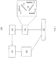
FIG. 1 depicts a system for determining the uniformity of powder layer distribution in accordance with one or more embodiments; and -
FIG. 2 depicts a method for determining the uniformity of powder layer distribution in accordance with one or more embodiments. - Currently, there are no definitive techniques to quantitatively determine the uniformity of powder layer distribution across the build plate. The uniformity of the powder layer directly affects the overall quality of the final product being built. The characteristics that can be affected by the uniformity include the final product's surface roughness, material homogeneity, porosity, etc. In addition, defects such as inter-layer delamination, inclusions, voids, over-melt/under-melt, etc. can occur without detection. The techniques described herein are focused on determining the uniformity of a powder layer distribution of a build plate.
- A detailed description of one or more embodiments of the disclosed apparatus and method are presented herein by way of exemplification and not limitation with reference to the Figures.
- Now referring to
FIG. 1 , asystem 100 for determining the uniformity of a powder layer distribution in accordance with one or more embodiments is shown. Thesystem 100 includes aprocessor 102. In one or more embodiments, theprocessor 102 is a data acquisition (DAQ) and image processor. Theprocessor 102 is coupled to theheat source 104. Theheat source 104 is used to pre-heat thepowder bed 110 for scanning the characteristics of the powder placed on thepowder bed 110. The powder layer emits thermal radiation when heated, and the powder layer also reflects incidental thermal infrared radiation to the camera system. The emission and reflection spectrum of the powder layer is known to be dependent upon the powder material layer thickness, powder particle size and distribution, packing density, and surface morphology. - The
processor 102 is also coupled to acamera controller 106 which is configured to control thecamera system 108. In one or more embodiments, thecamera system 108 can include one ormore bandpass filters 118. After the powder layer is pre-heated, the thermal radiation emitted from the powder layer is scanned by thecamera system 108. In one scenario, the thermal radiation signal is split into three or more wavelength ranges using thebandpass filters 118. The wavelength ranges can include but are not limited to Near infrared (NIR) = 0.75-1.4 µm; Short-wavelength infrared (SWIR) = 1.4-3 µm; Long-wavelength infrared (LWIR) = 3-8 µm; and Far infrared (FIR) = 15-1000 µm. In addition, thecamera system 108 can include one or more lens and focal plane arrays (FPA) 112, 114, and 116. In an embodiment, the thermal radiation signal is received by thecamera system 108 and is reflected by one ormore bandpass filters 118 so that the lights rays are transmitted through the nonreflective coated lenses andFPAs - The
heat source 104 and thecamera system 108 are controlled by theprocessor 102. In one or more embodiments, theprocessor 102 uses spectral angle mapping to process the multispectral images and convert multispectral images into a two-dimensional signature map of thepowder bed 108. - In one or more embodiments the spectral angle, Δα, is the inner product, or correlation coefficient between the test spectrum intensity versus wavelength I0(l) and the reference spectrum, where I(l) is the intensity and l is the wavelength. The spectral angle, Δα, can be calculated by the following equation:

- In an embodiment, small angles (Δα) between two spectra can indicate a high similarity between them, and high angles (Δα) can indicate low similarity. This technique is not affected by illumination factors because the angle between the vectors is not dependent on the vector magnitude. Therefore, this technique is not affected by the temperature, shadows, etc.
- In one or more embodiments, any combination of the above types of filters can be used together in the system. In one or more embodiments, the system can coupled to other sensor and process monitoring systems to collect data associated with the process. The data can be collected in real-time or non-real-time. In one or more embodiments, the system can use a multi-spectral (hyper-spectral imaging) infrared or microwave imaging system to scan the powder layer recoated across a build plate.
- In one or more embodiments, the
camera system 108 can include one or more cameras. In addition, the cameras can be infrared cameras that are sensitive to radiation over different wavelength bands. In other embodiments, a spectrometer can be used to measure radiation intensity against wavelengths at each pixel or focal point of the powder bed. - The intensity spectrum is used to accurately calculate the temperature of the different regions of an area emitting radiation. Also, multispectral sensing can collect other additional information from the surface that is emitting the radiation. Multispectral sensing provides a technique to distinguish between various materials based on their emissive and reflective properties of the surface layer of the respective materials.
- The results of the multispectral spectral analysis performed on the powder layer can be compared to reference information, where the results can be used to dynamically modify a fusion process to increase the quality of the build. As a nonlimiting example, the feedback can be used to optimize and control the laser power, scan speed, residence time, scanning strategy, etc., of the additive manufacturing build process. In another embodiment, the data that has been received from the powder bed layer can be used to match a powder coupon that is stored. The match can be determined based on the closest matching profile between the scanned powder layer and the stored powder layer. The system can be configured to identify sources of error and phenomenon that can lead to defects, porosity, poor part quality, and failure. The system ensures that all aspects of the additive manufacturing process are in control.
- Now referring to
FIG. 2 , amethod 200 for determining the uniformity of a powder layer distribution in accordance with one or more embodiments is shown.Block 202 provides pre-heating a powder layer. In one or more embodiments, the powder layer is pre-heated using a heat source such as a heat lamp. The heat source heats up the powder bed to a uniform temperature where the powder bed will emit thermal radiation. -
Block 204 provides scanning the powder layer. In one or more embodiments, a camera system performs a scan of the powder layer.Block 206 provides receiving a signal from the powder layer. In one or more embodiments, the camera system is configured to receive the thermal radiation reflected from the heated powder layer. -
Block 208 provides filtering the received signal. In one or more embodiments, the camera system is configured to filter the received thermal radiation from the powder layer. The camera system includes one or more bandpass filters to separate the radiation into different wavelength ranges to be analyzed. -
Block 210 provides measuring a radiation intensity of the signal over a range of wavelengths. In one or more embodiments, the camera system and heat lamp are controlled by a digital data acquisition and control system that processes the scanned thermal images. In addition, the information that is obtained from the scan can be used to control an additive manufacturing system. In an embodiment, the DAQ and the image processor uses a spectral angle mapping technique to automatically processes the multispectral image and convert them to a two-dimensional signature map of the powder bed. -
Block 212 provides comparing the measured radiation intensity to a reference spectrum. In one or more embodiments, the thermal images for each pixel of the thermal image of the powder bed are compared against a library of powder bed images. The results of the comparison can provide information about the characteristics of the powder bed. The library of powder coupons can be determined in a variety of ways. In one embodiment, the library can be generated by pre-scanning images of powder layers with known material properties. In another embodiment, the powder coupons can be scanned with the same multispectral system, or with a spectrometer, or sequentially by a sequence of monochromatic images of the powder coupons, in order to generate a characteristic spectrum (intensity versus wavelength) for each coupon. - In one or more embodiments, the techniques described herein can be utilized with metallic and non-metallic powders that are used for additive manufacturing powder bed fusion processes.
- In one or more embodiments, electromagnetic radiation is emitted by or reflected off of a powder bed to provide quantified information about the powder layer that can be used to optimize the laser power, scan speed, residence time, scanning strategy, etc., during an additive manufacturing build process. In one or more embodiments, the monitoring of the powder layer occurs during an additive manufacturing process. The monitoring allows the current process to be modified to increase the quality of the build.
- The techniques described herein can be used to optimize an additive manufacturing process and/or system. The information can be transmitted to an external system to control the quality of the product during manufacturing as opposed performing a quality check after each the final product has been completely manufactured. In addition, the efficiency of additive manufacturing production can be increased by correcting issues based on the current condition of the powder and configuration of the additive manufacturing system. The configuration of the system can be quickly detected and the performance of the system can be monitored.
- The techniques described herein provide a method for quantitatively evaluating the quality of new powder lots and recycled powders. In addition, the techniques provide a method for providing a permanent record for production quality assurance.
- Other techniques include using a single wavelength thermography, where an infrared (IR) camera generates a 2D image derived from the radiation intensity at each pixel, which is converted to temperature. The 2D analysis does not provide information about powder thickness uniformity, powder packing number or powder density distribution. However, a multi-spectral sensing technique, which is described herein, provides a more accurate calculation for temperature. The information obtained from the multi-spectral sensing technique can be used to optimize the powder bed fusion process. The techniques described herein also provide an in-process monitoring and closed loop control for managing an additive manufacturing process.
- The term "about" is intended to include the degree of error associated with measurement of the particular quantity based upon the equipment available at the time of filing the application. For example, "about" can include a range of ± 8% or 5%, or 2% of a given value.
- The terminology used herein is for the purpose of describing particular embodiments only and is not intended to be limiting of the present disclosure. As used herein, the singular forms "a", "an" and "the" are intended to include the plural forms as well, unless the context clearly indicates otherwise. It will be further understood that the terms "comprises" and/or "comprising," when used in this specification, specify the presence of stated features, integers, steps, operations, elements, and/or components, but do not preclude the presence or addition of one or more other features, integers, steps, operations, element components, and/or groups thereof.
- While the present disclosure has been described with reference to an exemplary embodiment or embodiments, it will be understood by those skilled in the art that various changes may be made and equivalents may be substituted for elements thereof without departing from the scope of the present disclosure. In addition, many modifications may be made to adapt a particular situation or material to the teachings of the present disclosure without departing from the essential scope thereof. Therefore, it is intended that the present disclosure not be limited to the particular embodiment disclosed as the best mode contemplated for carrying out this present disclosure, but that the present disclosure will include all embodiments falling within the scope of the claims.
Claims (15)
- A computer-implemented method (200) for determining the uniformity of powder layer distribution, the method comprising:pre-heating (202) a powder layer;scanning (204) the powder layer;receiving (206) a signal from the powder layer;filtering (208) the received signal;measuring (210) a radiation intensity of the signal over a range of wavelengths; andcomparing (212) the measured radiation intensity to a reference spectrum for the powder layer.
- The computer-implemented method of claim 1, wherein results of the comparing are transmitted to an additive manufacturing system.
- The computer-implemented method of claim 1 or 2, wherein filter and the measuring uses one or more focal plane arrays including different types of focal plane arrays comprising at least one of a near infrared, a short-wavelength infrared, a long-wavelength infrared or a far infrared type.
- The computer-implemented method of any preceding claim, wherein the comparing includes comparing each pixel of the received signal to the reference spectrum for the powder layer.
- The computer-implemented method of any preceding claim, further comprises generating a library of powder coupons by pre-scanning images of powder layers.
- The computer-implemented method of any preceding claim, further comprises converting a multispectral image of the powder layer to a two-dimensional signature map of the powder layer.
- The computer-implemented method of any preceding claim, wherein the filtering uses three or more types of focal plane arrays.
- The computer-implemented method of any preceding claim, further comprises monitoring the powder layer during an additive manufacturing process.
- The computer-implemented method of any preceding claim, further comprises responsive to the scanning, matching the powder layer to a stored powder layer coupon.
- A system (100) for determining the uniformity of powder layer distribution, the system comprises:a heat source (104) for pre-heating a powder layer;a camera system (108) for scanning the powder layer, the camera system (108) the includes one or more lenses, one or more focal plane arrays, and one or more bandpass filters; anda processor (102) for measuring a radiation intensity of a signal received from the powder layer, over a range of wavelengths, and comparing the measured radiation intensity to a reference spectrum for the powder layer.
- The system of claim 10, wherein the one or more focal plane arrays include different types of focal plane arrays including at least one of a near infrared, a short-wavelength infrared, a long-wavelength infrared or a far infrared type.
- The system of claim 10 or 11, wherein the processor is further configured to convert a multispectral image of the powder layer to a two-dimensional signature map of the powder layer.
- The system of claim 10, 11 or 12, wherein the processor (102) is further configured to perform a spectral angle mapping of the powder layer.
- The system of any of claims 10 to 13, wherein the comparing compares each pixel of the signal to the reference spectrum.
- The system of any of claims 10 to 14, wherein the processor is further configured to compare one or more stored spectrums of powder bed coupons to the received signal.
Applications Claiming Priority (1)
| Application Number | Priority Date | Filing Date | Title |
|---|---|---|---|
| US15/629,991 US10562229B2 (en) | 2017-06-22 | 2017-06-22 | Determining the uniformity of powder layer distribution across the build plate during a powder bed fusion process |
Publications (2)
| Publication Number | Publication Date |
|---|---|
| EP3417962A1 true EP3417962A1 (en) | 2018-12-26 |
| EP3417962B1 EP3417962B1 (en) | 2023-08-09 |
Family
ID=62748825
Family Applications (1)
| Application Number | Title | Priority Date | Filing Date |
|---|---|---|---|
| EP18179063.5A Active EP3417962B1 (en) | 2017-06-22 | 2018-06-21 | Determining the uniformity of powder layer distribution across the build plate during a powder bed fusion process |
Country Status (2)
| Country | Link |
|---|---|
| US (1) | US10562229B2 (en) |
| EP (1) | EP3417962B1 (en) |
Families Citing this family (5)
| Publication number | Priority date | Publication date | Assignee | Title |
|---|---|---|---|---|
| US11668658B2 (en) * | 2018-10-08 | 2023-06-06 | Araz Yacoubian | Multi-parameter inspection apparatus for monitoring of additive manufacturing parts |
| DE102021116862A1 (en) * | 2021-06-30 | 2023-01-05 | Rheinisch-Westfälische Technische Hochschule (RWTH) Aachen, Körperschaft des öffentlichen Rechts | Process for the additive manufacturing of porous, gas-permeable shaped bodies with controllable porosity |
| US12454004B2 (en) | 2022-11-09 | 2025-10-28 | Xerox Corporation | Real-time molten droplet analyzer with spatial modulation in additive manufacturing |
| US20240149355A1 (en) * | 2022-11-09 | 2024-05-09 | Palo Alto Research Center Incorporated | Real-time liquid metal droplet analyzer with spatial modulation in additive manufacturing |
| CN115625891B (en) * | 2022-12-21 | 2023-04-07 | 北京数字光芯集成电路设计有限公司 | A 3D printing device based on line scan MicroLED |
Citations (6)
| Publication number | Priority date | Publication date | Assignee | Title |
|---|---|---|---|---|
| EP1466718A2 (en) * | 2003-04-09 | 2004-10-13 | 3D Systems, Inc. | Sintering using thermal image feedback |
| US20080262659A1 (en) * | 2007-04-20 | 2008-10-23 | The Boeing Company | Methods and systems for controlling and adjusting heat distribution over a part bed |
| DE102007056984A1 (en) * | 2007-11-27 | 2009-05-28 | Eos Gmbh Electro Optical Systems | Method for producing a three-dimensional object by means of laser sintering |
| US8160296B2 (en) * | 2005-04-15 | 2012-04-17 | Mississippi State University Research And Technology Corporation | Change analyst |
| WO2016123549A1 (en) * | 2015-01-29 | 2016-08-04 | Alcoa Inc. | Systems and methods for modelling additively manufactured bodies |
| WO2016201390A1 (en) * | 2015-06-12 | 2016-12-15 | Materialise N.V. | System and method for ensuring consistency in additive manufacturing using thermal imaging |
Family Cites Families (3)
| Publication number | Priority date | Publication date | Assignee | Title |
|---|---|---|---|---|
| WO2015095544A1 (en) | 2013-12-18 | 2015-06-25 | Board Of Regents, The University Of Texas System | Real-time process control for additive manufacturing |
| EP3158302B1 (en) | 2014-06-18 | 2021-12-29 | Innopix, Inc. | Spectral imaging system for remote and noninvasive detection of target substances using spectral filter arrays and image capture arrays |
| US20180143147A1 (en) * | 2015-05-11 | 2018-05-24 | Board Of Regents, The University Of Texas System | Optical-coherence-tomography guided additive manufacturing and laser ablation of 3d-printed parts |
-
2017
- 2017-06-22 US US15/629,991 patent/US10562229B2/en active Active
-
2018
- 2018-06-21 EP EP18179063.5A patent/EP3417962B1/en active Active
Patent Citations (6)
| Publication number | Priority date | Publication date | Assignee | Title |
|---|---|---|---|---|
| EP1466718A2 (en) * | 2003-04-09 | 2004-10-13 | 3D Systems, Inc. | Sintering using thermal image feedback |
| US8160296B2 (en) * | 2005-04-15 | 2012-04-17 | Mississippi State University Research And Technology Corporation | Change analyst |
| US20080262659A1 (en) * | 2007-04-20 | 2008-10-23 | The Boeing Company | Methods and systems for controlling and adjusting heat distribution over a part bed |
| DE102007056984A1 (en) * | 2007-11-27 | 2009-05-28 | Eos Gmbh Electro Optical Systems | Method for producing a three-dimensional object by means of laser sintering |
| WO2016123549A1 (en) * | 2015-01-29 | 2016-08-04 | Alcoa Inc. | Systems and methods for modelling additively manufactured bodies |
| WO2016201390A1 (en) * | 2015-06-12 | 2016-12-15 | Materialise N.V. | System and method for ensuring consistency in additive manufacturing using thermal imaging |
Also Published As
| Publication number | Publication date |
|---|---|
| EP3417962B1 (en) | 2023-08-09 |
| US10562229B2 (en) | 2020-02-18 |
| US20180370142A1 (en) | 2018-12-27 |
Similar Documents
| Publication | Publication Date | Title |
|---|---|---|
| EP3417962B1 (en) | Determining the uniformity of powder layer distribution across the build plate during a powder bed fusion process | |
| Lane et al. | Thermographic measurements of the commercial laser powder bed fusion process at NIST | |
| Moylan et al. | Infrared thermography for laser-based powder bed fusion additive manufacturing processes | |
| Montazeri et al. | Sensor-based build condition monitoring in laser powder bed fusion additive manufacturing process using a spectral graph theoretic approach | |
| US12383960B2 (en) | In-situ process monitoring for powder bed fusion additive manufacturing (PBF AM) processes using multi-modal sensor fusion machine learning | |
| US8204294B2 (en) | Systems and methods for detecting defects in coatings utilizing color-based thermal mismatch | |
| Gerdes et al. | Hyperspectral imaging for prediction of surface roughness in laser powder bed fusion | |
| Yan et al. | Non-destructive testing of composite fiber materials with hyperspectral imaging—Evaluative studies in the EU H2020 FibreEUse project | |
| US20160098825A1 (en) | Feature extraction method and system for additive manufacturing | |
| US11338390B2 (en) | Two-color high speed thermal imaging system for laser-based additive manufacturing process monitoring | |
| KR20160032593A (en) | Method and apparatus for detecting defects on the glass substrate using hyper-spectral imaging | |
| KR20180038672A (en) | Apparatus of Defect Detection Using Infrared Thermography Technique | |
| US20210197282A1 (en) | Method and apparatus for estimating height of 3d printing object formed during 3d printing process, and 3d printing system having the same | |
| EP2141489B1 (en) | Thermographic inspection apparatus | |
| US20210191372A1 (en) | Analysis of additive manufacturing processes | |
| US11890808B2 (en) | In-situ digital image correlation and thermal monitoring in directed energy deposition | |
| Cullinan et al. | Methodology for determination of the emissivity of metal powders and uncertainty quantification using an infrared camera and thermocouples | |
| Becker et al. | In-situ monitoring of the Laser Powder Bed Fusion build process via bi-chromatic optical tomography | |
| US20220404209A1 (en) | Apparatus for thermal sensing during additive manufacturing and methods that accomplish the same | |
| Jiang et al. | Control-oriented mechatronic design and data analytics for quality-assured laser powder bed fusion additive manufacturing | |
| WO2013010871A1 (en) | Method and system for emissivity determination | |
| DE102016212810B4 (en) | Process and measuring system for testing a component using active thermography | |
| Larsen et al. | Classification of black plastic types by hyperspectral imaging based on long-wave infrared emission spectroscopy | |
| Jørgensen et al. | Surface temperature determination using long range thermal emission spectroscopy based on a first order scanning Fabry-Pérot interferometer | |
| Li et al. | Overview of in-situ temperature measurement for metallic additive manufacturing: how and then what |
Legal Events
| Date | Code | Title | Description |
|---|---|---|---|
| PUAI | Public reference made under article 153(3) epc to a published international application that has entered the european phase |
Free format text: ORIGINAL CODE: 0009012 |
|
| STAA | Information on the status of an ep patent application or granted ep patent |
Free format text: STATUS: THE APPLICATION HAS BEEN PUBLISHED |
|
| AK | Designated contracting states |
Kind code of ref document: A1 Designated state(s): AL AT BE BG CH CY CZ DE DK EE ES FI FR GB GR HR HU IE IS IT LI LT LU LV MC MK MT NL NO PL PT RO RS SE SI SK SM TR |
|
| AX | Request for extension of the european patent |
Extension state: BA ME |
|
| STAA | Information on the status of an ep patent application or granted ep patent |
Free format text: STATUS: REQUEST FOR EXAMINATION WAS MADE |
|
| 17P | Request for examination filed |
Effective date: 20190626 |
|
| RBV | Designated contracting states (corrected) |
Designated state(s): AL AT BE BG CH CY CZ DE DK EE ES FI FR GB GR HR HU IE IS IT LI LT LU LV MC MK MT NL NO PL PT RO RS SE SI SK SM TR |
|
| STAA | Information on the status of an ep patent application or granted ep patent |
Free format text: STATUS: EXAMINATION IS IN PROGRESS |
|
| 17Q | First examination report despatched |
Effective date: 20200214 |
|
| REG | Reference to a national code |
Ref country code: DE Ref legal event code: R079 Ipc: B29C0064165000 Ref country code: DE Ref legal event code: R079 Ref document number: 602018054895 Country of ref document: DE Free format text: PREVIOUS MAIN CLASS: B22F0003105000 Ipc: B29C0064165000 |
|
| GRAP | Despatch of communication of intention to grant a patent |
Free format text: ORIGINAL CODE: EPIDOSNIGR1 |
|
| STAA | Information on the status of an ep patent application or granted ep patent |
Free format text: STATUS: GRANT OF PATENT IS INTENDED |
|
| RIC1 | Information provided on ipc code assigned before grant |
Ipc: B22F 12/90 20210101ALN20230209BHEP Ipc: B22F 12/45 20210101ALN20230209BHEP Ipc: B22F 10/366 20210101ALN20230209BHEP Ipc: B22F 10/36 20210101ALN20230209BHEP Ipc: B22F 10/34 20210101ALN20230209BHEP Ipc: B22F 10/28 20210101ALN20230209BHEP Ipc: B22F 10/25 20210101ALN20230209BHEP Ipc: B33Y 50/02 20150101ALN20230209BHEP Ipc: B33Y 30/00 20150101ALN20230209BHEP Ipc: B33Y 10/00 20150101ALN20230209BHEP Ipc: G01J 5/60 20060101ALI20230209BHEP Ipc: B29C 64/153 20170101ALI20230209BHEP Ipc: G06T 7/00 20060101ALI20230209BHEP Ipc: G01J 5/48 20060101ALI20230209BHEP Ipc: B33Y 40/10 20200101ALI20230209BHEP Ipc: B22F 12/13 20210101ALI20230209BHEP Ipc: B29C 64/393 20170101ALI20230209BHEP Ipc: B29C 64/321 20170101ALI20230209BHEP Ipc: B29C 64/295 20170101ALI20230209BHEP Ipc: B29C 64/205 20170101ALI20230209BHEP Ipc: B29C 64/165 20170101AFI20230209BHEP |
|
| INTG | Intention to grant announced |
Effective date: 20230302 |
|
| RIN1 | Information on inventor provided before grant (corrected) |
Inventor name: MIRONETS, SERGEY Inventor name: STAROSELSKY, ALEXANDER Inventor name: MARTIN, THOMAS J. |
|
| GRAS | Grant fee paid |
Free format text: ORIGINAL CODE: EPIDOSNIGR3 |
|
| GRAA | (expected) grant |
Free format text: ORIGINAL CODE: 0009210 |
|
| STAA | Information on the status of an ep patent application or granted ep patent |
Free format text: STATUS: THE PATENT HAS BEEN GRANTED |
|
| AK | Designated contracting states |
Kind code of ref document: B1 Designated state(s): AL AT BE BG CH CY CZ DE DK EE ES FI FR GB GR HR HU IE IS IT LI LT LU LV MC MK MT NL NO PL PT RO RS SE SI SK SM TR |
|
| REG | Reference to a national code |
Ref country code: GB Ref legal event code: FG4D |
|
| REG | Reference to a national code |
Ref country code: CH Ref legal event code: EP |
|
| REG | Reference to a national code |
Ref country code: IE Ref legal event code: FG4D |
|
| REG | Reference to a national code |
Ref country code: DE Ref legal event code: R096 Ref document number: 602018054895 Country of ref document: DE |
|
| REG | Reference to a national code |
Ref country code: LT Ref legal event code: MG9D |
|
| REG | Reference to a national code |
Ref country code: NL Ref legal event code: MP Effective date: 20230809 |
|
| REG | Reference to a national code |
Ref country code: AT Ref legal event code: MK05 Ref document number: 1597017 Country of ref document: AT Kind code of ref document: T Effective date: 20230809 |
|
| PG25 | Lapsed in a contracting state [announced via postgrant information from national office to epo] |
Ref country code: GR Free format text: LAPSE BECAUSE OF FAILURE TO SUBMIT A TRANSLATION OF THE DESCRIPTION OR TO PAY THE FEE WITHIN THE PRESCRIBED TIME-LIMIT Effective date: 20231110 |
|
| PG25 | Lapsed in a contracting state [announced via postgrant information from national office to epo] |
Ref country code: IS Free format text: LAPSE BECAUSE OF FAILURE TO SUBMIT A TRANSLATION OF THE DESCRIPTION OR TO PAY THE FEE WITHIN THE PRESCRIBED TIME-LIMIT Effective date: 20231209 |
|
| PG25 | Lapsed in a contracting state [announced via postgrant information from national office to epo] |
Ref country code: SE Free format text: LAPSE BECAUSE OF FAILURE TO SUBMIT A TRANSLATION OF THE DESCRIPTION OR TO PAY THE FEE WITHIN THE PRESCRIBED TIME-LIMIT Effective date: 20230809 Ref country code: RS Free format text: LAPSE BECAUSE OF FAILURE TO SUBMIT A TRANSLATION OF THE DESCRIPTION OR TO PAY THE FEE WITHIN THE PRESCRIBED TIME-LIMIT Effective date: 20230809 Ref country code: PT Free format text: LAPSE BECAUSE OF FAILURE TO SUBMIT A TRANSLATION OF THE DESCRIPTION OR TO PAY THE FEE WITHIN THE PRESCRIBED TIME-LIMIT Effective date: 20231211 Ref country code: NO Free format text: LAPSE BECAUSE OF FAILURE TO SUBMIT A TRANSLATION OF THE DESCRIPTION OR TO PAY THE FEE WITHIN THE PRESCRIBED TIME-LIMIT Effective date: 20231109 Ref country code: NL Free format text: LAPSE BECAUSE OF FAILURE TO SUBMIT A TRANSLATION OF THE DESCRIPTION OR TO PAY THE FEE WITHIN THE PRESCRIBED TIME-LIMIT Effective date: 20230809 Ref country code: LV Free format text: LAPSE BECAUSE OF FAILURE TO SUBMIT A TRANSLATION OF THE DESCRIPTION OR TO PAY THE FEE WITHIN THE PRESCRIBED TIME-LIMIT Effective date: 20230809 Ref country code: LT Free format text: LAPSE BECAUSE OF FAILURE TO SUBMIT A TRANSLATION OF THE DESCRIPTION OR TO PAY THE FEE WITHIN THE PRESCRIBED TIME-LIMIT Effective date: 20230809 Ref country code: IS Free format text: LAPSE BECAUSE OF FAILURE TO SUBMIT A TRANSLATION OF THE DESCRIPTION OR TO PAY THE FEE WITHIN THE PRESCRIBED TIME-LIMIT Effective date: 20231209 Ref country code: HR Free format text: LAPSE BECAUSE OF FAILURE TO SUBMIT A TRANSLATION OF THE DESCRIPTION OR TO PAY THE FEE WITHIN THE PRESCRIBED TIME-LIMIT Effective date: 20230809 Ref country code: GR Free format text: LAPSE BECAUSE OF FAILURE TO SUBMIT A TRANSLATION OF THE DESCRIPTION OR TO PAY THE FEE WITHIN THE PRESCRIBED TIME-LIMIT Effective date: 20231110 Ref country code: FI Free format text: LAPSE BECAUSE OF FAILURE TO SUBMIT A TRANSLATION OF THE DESCRIPTION OR TO PAY THE FEE WITHIN THE PRESCRIBED TIME-LIMIT Effective date: 20230809 Ref country code: AT Free format text: LAPSE BECAUSE OF FAILURE TO SUBMIT A TRANSLATION OF THE DESCRIPTION OR TO PAY THE FEE WITHIN THE PRESCRIBED TIME-LIMIT Effective date: 20230809 |
|
| PG25 | Lapsed in a contracting state [announced via postgrant information from national office to epo] |
Ref country code: PL Free format text: LAPSE BECAUSE OF FAILURE TO SUBMIT A TRANSLATION OF THE DESCRIPTION OR TO PAY THE FEE WITHIN THE PRESCRIBED TIME-LIMIT Effective date: 20230809 |
|
| PG25 | Lapsed in a contracting state [announced via postgrant information from national office to epo] |
Ref country code: ES Free format text: LAPSE BECAUSE OF FAILURE TO SUBMIT A TRANSLATION OF THE DESCRIPTION OR TO PAY THE FEE WITHIN THE PRESCRIBED TIME-LIMIT Effective date: 20230809 |
|
| PG25 | Lapsed in a contracting state [announced via postgrant information from national office to epo] |
Ref country code: SM Free format text: LAPSE BECAUSE OF FAILURE TO SUBMIT A TRANSLATION OF THE DESCRIPTION OR TO PAY THE FEE WITHIN THE PRESCRIBED TIME-LIMIT Effective date: 20230809 Ref country code: RO Free format text: LAPSE BECAUSE OF FAILURE TO SUBMIT A TRANSLATION OF THE DESCRIPTION OR TO PAY THE FEE WITHIN THE PRESCRIBED TIME-LIMIT Effective date: 20230809 Ref country code: ES Free format text: LAPSE BECAUSE OF FAILURE TO SUBMIT A TRANSLATION OF THE DESCRIPTION OR TO PAY THE FEE WITHIN THE PRESCRIBED TIME-LIMIT Effective date: 20230809 Ref country code: EE Free format text: LAPSE BECAUSE OF FAILURE TO SUBMIT A TRANSLATION OF THE DESCRIPTION OR TO PAY THE FEE WITHIN THE PRESCRIBED TIME-LIMIT Effective date: 20230809 Ref country code: DK Free format text: LAPSE BECAUSE OF FAILURE TO SUBMIT A TRANSLATION OF THE DESCRIPTION OR TO PAY THE FEE WITHIN THE PRESCRIBED TIME-LIMIT Effective date: 20230809 Ref country code: CZ Free format text: LAPSE BECAUSE OF FAILURE TO SUBMIT A TRANSLATION OF THE DESCRIPTION OR TO PAY THE FEE WITHIN THE PRESCRIBED TIME-LIMIT Effective date: 20230809 Ref country code: SK Free format text: LAPSE BECAUSE OF FAILURE TO SUBMIT A TRANSLATION OF THE DESCRIPTION OR TO PAY THE FEE WITHIN THE PRESCRIBED TIME-LIMIT Effective date: 20230809 |
|
| REG | Reference to a national code |
Ref country code: DE Ref legal event code: R097 Ref document number: 602018054895 Country of ref document: DE |
|
| PG25 | Lapsed in a contracting state [announced via postgrant information from national office to epo] |
Ref country code: IT Free format text: LAPSE BECAUSE OF FAILURE TO SUBMIT A TRANSLATION OF THE DESCRIPTION OR TO PAY THE FEE WITHIN THE PRESCRIBED TIME-LIMIT Effective date: 20230809 |
|
| PLBE | No opposition filed within time limit |
Free format text: ORIGINAL CODE: 0009261 |
|
| STAA | Information on the status of an ep patent application or granted ep patent |
Free format text: STATUS: NO OPPOSITION FILED WITHIN TIME LIMIT |
|
| 26N | No opposition filed |
Effective date: 20240513 |
|
| PG25 | Lapsed in a contracting state [announced via postgrant information from national office to epo] |
Ref country code: SI Free format text: LAPSE BECAUSE OF FAILURE TO SUBMIT A TRANSLATION OF THE DESCRIPTION OR TO PAY THE FEE WITHIN THE PRESCRIBED TIME-LIMIT Effective date: 20230809 |
|
| PG25 | Lapsed in a contracting state [announced via postgrant information from national office to epo] |
Ref country code: BG Free format text: LAPSE BECAUSE OF FAILURE TO SUBMIT A TRANSLATION OF THE DESCRIPTION OR TO PAY THE FEE WITHIN THE PRESCRIBED TIME-LIMIT Effective date: 20230809 |
|
| PG25 | Lapsed in a contracting state [announced via postgrant information from national office to epo] |
Ref country code: BG Free format text: LAPSE BECAUSE OF FAILURE TO SUBMIT A TRANSLATION OF THE DESCRIPTION OR TO PAY THE FEE WITHIN THE PRESCRIBED TIME-LIMIT Effective date: 20230809 |
|
| PG25 | Lapsed in a contracting state [announced via postgrant information from national office to epo] |
Ref country code: MC Free format text: LAPSE BECAUSE OF FAILURE TO SUBMIT A TRANSLATION OF THE DESCRIPTION OR TO PAY THE FEE WITHIN THE PRESCRIBED TIME-LIMIT Effective date: 20230809 |
|
| REG | Reference to a national code |
Ref country code: CH Ref legal event code: PL |
|
| PG25 | Lapsed in a contracting state [announced via postgrant information from national office to epo] |
Ref country code: LU Free format text: LAPSE BECAUSE OF NON-PAYMENT OF DUE FEES Effective date: 20240621 |
|
| PG25 | Lapsed in a contracting state [announced via postgrant information from national office to epo] |
Ref country code: IE Free format text: LAPSE BECAUSE OF NON-PAYMENT OF DUE FEES Effective date: 20240621 |
|
| PG25 | Lapsed in a contracting state [announced via postgrant information from national office to epo] |
Ref country code: BE Free format text: LAPSE BECAUSE OF NON-PAYMENT OF DUE FEES Effective date: 20240630 Ref country code: CH Free format text: LAPSE BECAUSE OF NON-PAYMENT OF DUE FEES Effective date: 20240630 |
|
| REG | Reference to a national code |
Ref country code: BE Ref legal event code: MM Effective date: 20240630 |
|
| PGFP | Annual fee paid to national office [announced via postgrant information from national office to epo] |
Ref country code: DE Payment date: 20250520 Year of fee payment: 8 |
|
| PGFP | Annual fee paid to national office [announced via postgrant information from national office to epo] |
Ref country code: GB Payment date: 20250520 Year of fee payment: 8 |
|
| PGFP | Annual fee paid to national office [announced via postgrant information from national office to epo] |
Ref country code: FR Payment date: 20250520 Year of fee payment: 8 |
|
| PG25 | Lapsed in a contracting state [announced via postgrant information from national office to epo] |
Ref country code: CY Free format text: LAPSE BECAUSE OF FAILURE TO SUBMIT A TRANSLATION OF THE DESCRIPTION OR TO PAY THE FEE WITHIN THE PRESCRIBED TIME-LIMIT; INVALID AB INITIO Effective date: 20180621 |
|
| P01 | Opt-out of the competence of the unified patent court (upc) registered |
Free format text: CASE NUMBER: UPC_APP_0017159_3417962/2025 Effective date: 20251211 |
|
| PG25 | Lapsed in a contracting state [announced via postgrant information from national office to epo] |
Ref country code: HU Free format text: LAPSE BECAUSE OF FAILURE TO SUBMIT A TRANSLATION OF THE DESCRIPTION OR TO PAY THE FEE WITHIN THE PRESCRIBED TIME-LIMIT; INVALID AB INITIO Effective date: 20180621 |