EP3417820A1 - Energy surgery device - Google Patents
Energy surgery device Download PDFInfo
- Publication number
- EP3417820A1 EP3417820A1 EP16890467.0A EP16890467A EP3417820A1 EP 3417820 A1 EP3417820 A1 EP 3417820A1 EP 16890467 A EP16890467 A EP 16890467A EP 3417820 A1 EP3417820 A1 EP 3417820A1
- Authority
- EP
- European Patent Office
- Prior art keywords
- blood vessel
- grasping
- wall thickness
- grasped
- energy
- Prior art date
- Legal status (The legal status is an assumption and is not a legal conclusion. Google has not performed a legal analysis and makes no representation as to the accuracy of the status listed.)
- Withdrawn
Links
- 238000001356 surgical procedure Methods 0.000 title description 2
- 210000004204 blood vessel Anatomy 0.000 claims abstract description 328
- 238000001514 detection method Methods 0.000 claims description 13
- 239000012636 effector Substances 0.000 description 70
- 230000004048 modification Effects 0.000 description 51
- 238000012986 modification Methods 0.000 description 51
- 238000006073 displacement reaction Methods 0.000 description 20
- 230000002685 pulmonary effect Effects 0.000 description 18
- 230000007423 decrease Effects 0.000 description 17
- 230000009885 systemic effect Effects 0.000 description 15
- 238000010336 energy treatment Methods 0.000 description 14
- 210000000078 claw Anatomy 0.000 description 11
- 230000008602 contraction Effects 0.000 description 10
- 238000007789 sealing Methods 0.000 description 9
- 238000002604 ultrasonography Methods 0.000 description 9
- 238000010438 heat treatment Methods 0.000 description 8
- XLYOFNOQVPJJNP-UHFFFAOYSA-N water Substances O XLYOFNOQVPJJNP-UHFFFAOYSA-N 0.000 description 8
- 229920001222 biopolymer Polymers 0.000 description 4
- 239000008280 blood Substances 0.000 description 4
- 210000004369 blood Anatomy 0.000 description 4
- 230000004088 pulmonary circulation Effects 0.000 description 4
- 230000001839 systemic circulation Effects 0.000 description 4
- 230000000694 effects Effects 0.000 description 3
- 210000005246 left atrium Anatomy 0.000 description 3
- 210000005240 left ventricle Anatomy 0.000 description 3
- 210000005245 right atrium Anatomy 0.000 description 3
- 210000005241 right ventricle Anatomy 0.000 description 3
- 210000001367 artery Anatomy 0.000 description 2
- 230000005540 biological transmission Effects 0.000 description 2
- 238000006243 chemical reaction Methods 0.000 description 2
- 238000010586 diagram Methods 0.000 description 2
- 210000004072 lung Anatomy 0.000 description 2
- 238000000034 method Methods 0.000 description 2
- 230000037361 pathway Effects 0.000 description 2
- 229920001343 polytetrafluoroethylene Polymers 0.000 description 2
- 239000004810 polytetrafluoroethylene Substances 0.000 description 2
- 210000001147 pulmonary artery Anatomy 0.000 description 2
- 210000003492 pulmonary vein Anatomy 0.000 description 2
- 210000003462 vein Anatomy 0.000 description 2
- 238000005299 abrasion Methods 0.000 description 1
- 238000005452 bending Methods 0.000 description 1
- 230000008878 coupling Effects 0.000 description 1
- 238000010168 coupling process Methods 0.000 description 1
- 238000005859 coupling reaction Methods 0.000 description 1
- 239000012777 electrically insulating material Substances 0.000 description 1
- 230000006870 function Effects 0.000 description 1
- -1 polytetrafluoroethylene Polymers 0.000 description 1
- 230000008569 process Effects 0.000 description 1
- 210000000115 thoracic cavity Anatomy 0.000 description 1
Images





Classifications
-
- A—HUMAN NECESSITIES
- A61—MEDICAL OR VETERINARY SCIENCE; HYGIENE
- A61B—DIAGNOSIS; SURGERY; IDENTIFICATION
- A61B17/00—Surgical instruments, devices or methods
- A61B17/32—Surgical cutting instruments
- A61B17/320068—Surgical cutting instruments using mechanical vibrations, e.g. ultrasonic
- A61B17/320092—Surgical cutting instruments using mechanical vibrations, e.g. ultrasonic with additional movable means for clamping or cutting tissue, e.g. with a pivoting jaw
-
- A—HUMAN NECESSITIES
- A61—MEDICAL OR VETERINARY SCIENCE; HYGIENE
- A61B—DIAGNOSIS; SURGERY; IDENTIFICATION
- A61B17/00—Surgical instruments, devices or methods
-
- A—HUMAN NECESSITIES
- A61—MEDICAL OR VETERINARY SCIENCE; HYGIENE
- A61B—DIAGNOSIS; SURGERY; IDENTIFICATION
- A61B18/00—Surgical instruments, devices or methods for transferring non-mechanical forms of energy to or from the body
- A61B18/04—Surgical instruments, devices or methods for transferring non-mechanical forms of energy to or from the body by heating
- A61B18/12—Surgical instruments, devices or methods for transferring non-mechanical forms of energy to or from the body by heating by passing a current through the tissue to be heated, e.g. high-frequency current
- A61B18/14—Probes or electrodes therefor
- A61B18/1442—Probes having pivoting end effectors, e.g. forceps
- A61B18/1445—Probes having pivoting end effectors, e.g. forceps at the distal end of a shaft, e.g. forceps or scissors at the end of a rigid rod
-
- A—HUMAN NECESSITIES
- A61—MEDICAL OR VETERINARY SCIENCE; HYGIENE
- A61B—DIAGNOSIS; SURGERY; IDENTIFICATION
- A61B17/00—Surgical instruments, devices or methods
- A61B2017/00017—Electrical control of surgical instruments
- A61B2017/00022—Sensing or detecting at the treatment site
- A61B2017/00057—Light
-
- A—HUMAN NECESSITIES
- A61—MEDICAL OR VETERINARY SCIENCE; HYGIENE
- A61B—DIAGNOSIS; SURGERY; IDENTIFICATION
- A61B17/00—Surgical instruments, devices or methods
- A61B2017/00367—Details of actuation of instruments, e.g. relations between pushing buttons, or the like, and activation of the tool, working tip, or the like
- A61B2017/00398—Details of actuation of instruments, e.g. relations between pushing buttons, or the like, and activation of the tool, working tip, or the like using powered actuators, e.g. stepper motors, solenoids
-
- A—HUMAN NECESSITIES
- A61—MEDICAL OR VETERINARY SCIENCE; HYGIENE
- A61B—DIAGNOSIS; SURGERY; IDENTIFICATION
- A61B17/00—Surgical instruments, devices or methods
- A61B2017/00743—Type of operation; Specification of treatment sites
- A61B2017/00778—Operations on blood vessels
-
- A—HUMAN NECESSITIES
- A61—MEDICAL OR VETERINARY SCIENCE; HYGIENE
- A61B—DIAGNOSIS; SURGERY; IDENTIFICATION
- A61B17/00—Surgical instruments, devices or methods
- A61B17/32—Surgical cutting instruments
- A61B17/320068—Surgical cutting instruments using mechanical vibrations, e.g. ultrasonic
- A61B2017/320082—Surgical cutting instruments using mechanical vibrations, e.g. ultrasonic for incising tissue
-
- A—HUMAN NECESSITIES
- A61—MEDICAL OR VETERINARY SCIENCE; HYGIENE
- A61B—DIAGNOSIS; SURGERY; IDENTIFICATION
- A61B17/00—Surgical instruments, devices or methods
- A61B17/32—Surgical cutting instruments
- A61B17/320068—Surgical cutting instruments using mechanical vibrations, e.g. ultrasonic
- A61B17/320092—Surgical cutting instruments using mechanical vibrations, e.g. ultrasonic with additional movable means for clamping or cutting tissue, e.g. with a pivoting jaw
- A61B2017/320095—Surgical cutting instruments using mechanical vibrations, e.g. ultrasonic with additional movable means for clamping or cutting tissue, e.g. with a pivoting jaw with sealing or cauterizing means
-
- A—HUMAN NECESSITIES
- A61—MEDICAL OR VETERINARY SCIENCE; HYGIENE
- A61B—DIAGNOSIS; SURGERY; IDENTIFICATION
- A61B18/00—Surgical instruments, devices or methods for transferring non-mechanical forms of energy to or from the body
- A61B2018/00315—Surgical instruments, devices or methods for transferring non-mechanical forms of energy to or from the body for treatment of particular body parts
- A61B2018/00345—Vascular system
- A61B2018/00404—Blood vessels other than those in or around the heart
-
- A—HUMAN NECESSITIES
- A61—MEDICAL OR VETERINARY SCIENCE; HYGIENE
- A61B—DIAGNOSIS; SURGERY; IDENTIFICATION
- A61B18/00—Surgical instruments, devices or methods for transferring non-mechanical forms of energy to or from the body
- A61B2018/00571—Surgical instruments, devices or methods for transferring non-mechanical forms of energy to or from the body for achieving a particular surgical effect
- A61B2018/00589—Coagulation
-
- A—HUMAN NECESSITIES
- A61—MEDICAL OR VETERINARY SCIENCE; HYGIENE
- A61B—DIAGNOSIS; SURGERY; IDENTIFICATION
- A61B18/00—Surgical instruments, devices or methods for transferring non-mechanical forms of energy to or from the body
- A61B2018/00571—Surgical instruments, devices or methods for transferring non-mechanical forms of energy to or from the body for achieving a particular surgical effect
- A61B2018/00601—Cutting
-
- A—HUMAN NECESSITIES
- A61—MEDICAL OR VETERINARY SCIENCE; HYGIENE
- A61B—DIAGNOSIS; SURGERY; IDENTIFICATION
- A61B18/00—Surgical instruments, devices or methods for transferring non-mechanical forms of energy to or from the body
- A61B2018/00571—Surgical instruments, devices or methods for transferring non-mechanical forms of energy to or from the body for achieving a particular surgical effect
- A61B2018/00607—Coagulation and cutting with the same instrument
-
- A—HUMAN NECESSITIES
- A61—MEDICAL OR VETERINARY SCIENCE; HYGIENE
- A61B—DIAGNOSIS; SURGERY; IDENTIFICATION
- A61B18/00—Surgical instruments, devices or methods for transferring non-mechanical forms of energy to or from the body
- A61B2018/00571—Surgical instruments, devices or methods for transferring non-mechanical forms of energy to or from the body for achieving a particular surgical effect
- A61B2018/0063—Sealing
-
- A—HUMAN NECESSITIES
- A61—MEDICAL OR VETERINARY SCIENCE; HYGIENE
- A61B—DIAGNOSIS; SURGERY; IDENTIFICATION
- A61B18/00—Surgical instruments, devices or methods for transferring non-mechanical forms of energy to or from the body
- A61B2018/00994—Surgical instruments, devices or methods for transferring non-mechanical forms of energy to or from the body combining two or more different kinds of non-mechanical energy or combining one or more non-mechanical energies with ultrasound
-
- A—HUMAN NECESSITIES
- A61—MEDICAL OR VETERINARY SCIENCE; HYGIENE
- A61B—DIAGNOSIS; SURGERY; IDENTIFICATION
- A61B90/00—Instruments, implements or accessories specially adapted for surgery or diagnosis and not covered by any of the groups A61B1/00 - A61B50/00, e.g. for luxation treatment or for protecting wound edges
- A61B90/03—Automatic limiting or abutting means, e.g. for safety
- A61B2090/033—Abutting means, stops, e.g. abutting on tissue or skin
- A61B2090/034—Abutting means, stops, e.g. abutting on tissue or skin abutting on parts of the device itself
-
- A—HUMAN NECESSITIES
- A61—MEDICAL OR VETERINARY SCIENCE; HYGIENE
- A61B—DIAGNOSIS; SURGERY; IDENTIFICATION
- A61B90/00—Instruments, implements or accessories specially adapted for surgery or diagnosis and not covered by any of the groups A61B1/00 - A61B50/00, e.g. for luxation treatment or for protecting wound edges
- A61B90/06—Measuring instruments not otherwise provided for
- A61B2090/064—Measuring instruments not otherwise provided for for measuring force, pressure or mechanical tension
-
- A—HUMAN NECESSITIES
- A61—MEDICAL OR VETERINARY SCIENCE; HYGIENE
- A61B—DIAGNOSIS; SURGERY; IDENTIFICATION
- A61B90/00—Instruments, implements or accessories specially adapted for surgery or diagnosis and not covered by any of the groups A61B1/00 - A61B50/00, e.g. for luxation treatment or for protecting wound edges
- A61B90/06—Measuring instruments not otherwise provided for
- A61B2090/067—Measuring instruments not otherwise provided for for measuring angles
-
- A—HUMAN NECESSITIES
- A61—MEDICAL OR VETERINARY SCIENCE; HYGIENE
- A61B—DIAGNOSIS; SURGERY; IDENTIFICATION
- A61B90/00—Instruments, implements or accessories specially adapted for surgery or diagnosis and not covered by any of the groups A61B1/00 - A61B50/00, e.g. for luxation treatment or for protecting wound edges
- A61B90/36—Image-producing devices or illumination devices not otherwise provided for
- A61B90/37—Surgical systems with images on a monitor during operation
- A61B2090/378—Surgical systems with images on a monitor during operation using ultrasound
- A61B2090/3782—Surgical systems with images on a monitor during operation using ultrasound transmitter or receiver in catheter or minimal invasive instrument
- A61B2090/3784—Surgical systems with images on a monitor during operation using ultrasound transmitter or receiver in catheter or minimal invasive instrument both receiver and transmitter being in the instrument or receiver being also transmitter
Definitions
- the present invention relates to an energy surgical instrument which grasps a treatment target such as living tissue between a pair of grasping pieces to conduct treatment using treatment energy such as an ultrasonic vibration and a high-frequency current.
- Patent literature 1 discloses an energy surgical instrument which grasps a treatment target such as living tissue between a pair of grasping pieces and applies treatment energy to the grasped treatment target to allow the treatment target to be sealed.
- Patent literature 1 U.S. Patent Application Publication No. 2011/0118736
- Blood vessels to be treated may vary in wall thickness according to position, type and the like.
- blood vessels that differ in wall thickness may be sealed (coagulated) with an energy surgical instrument that is similar to that of patent literature 1.
- an energy surgical instrument that is similar to that of patent literature 1.
- the blood vessels are grasped with the same grasping force, it may affect the sealing performance of the blood vessels.
- the present invention has been made to solve the foregoing problem and its object is to provide an energy surgical instrument capable of achieving treatment performance as appropriate even though blood vessels are different in wall thickness.
- an energy surgical instrument includes a first grasping piece, a second grasping piece which is allowed to open and close relative to the first grasping piece and which is allowed to grasp a blood vessel between the first grasping piece and the second grasping piece, an energy application unit provided in at least one of the first grasping piece and the second grasping piece, which applies treatment energy to the blood vessel grasped between the first grasping piece and the second grasping piece to treat the blood vessel, a setting unit which sets information regarding a wall thickness of the blood vessel, and a grasping force adjustment unit which adjusts a grasping force to grasp the blood vessel between the first grasping piece and the second grasping piece to a first grasping force when the wall thickness set by the setting unit is larger than a predetermined thickness and adjusting the grasping force to a second grasping force, which is larger than the first grasping force, when the wall thickness set by the setting unit is equal to or smaller than the predetermined thickness.
- an energy surgical instrument capable of achieving treatment performance as appropriate even though blood vessels are different in wall thickness.
- FIG. 1 is a view showing an outward appearance of an energy surgical instrument (treatment system) 1 according to a first embodiment.
- the energy surgical instrument 1 includes an energy treatment instrument 2 and an energy controller 3.
- the energy treatment instrument 2 has a longitudinal axis C.
- one side of the direction along the longitudinal axis C is defined as a distal side (arrow C1 side) and the side opposite to the distal side is defined as a proximal side (arrow C2 side).
- the direction that is parallel to the longitudinal axis C is defined as a longitudinal direction.
- the energy treatment instrument 2 includes a holdable housing 4.
- a sheath 5 extends along the longitudinal axis C and is inserted into the housing 4 from the distal side.
- the central axis of the sheath 5 is substantially aligned with the longitudinal axis C.
- An end effector 6 is provided at a distal portion of the sheath 5.
- One end of a cable 7 is connected to the housing 4.
- the other end of the cable 7 is separably connected to the energy controller 3.
- the housing 4 includes a grip 11.
- a handle 12 is revolvably attached to the housing 4.
- the handle 12 revolves relative to the housing 4 and thus opens or closes relative to the grip 11.
- the handle 12 is located on the distal side of the grip 11, which is, however, not restrictive.
- the handle 12 may be located on the proximal side of the grip 11.
- the handle 12 can open and close in a direction substantially parallel to the longitudinal axis C relative to the grip 11, which is, however, not restrictive.
- the handle 12 may open and close in a direction substantially perpendicularly to the longitudinal axis C relative to the grip 11.
- the end effector 6 includes a first grasping piece 13 and a second grasping piece 14 which can open and close relative to the first grasping piece 13.
- the first grasping piece 13 has a first opposing surface 31 opposed to the second grasping piece 14.
- the second grasping piece 14 has a second opposing surface 32 opposed to the first grasping piece 13 (first opposing surface 31).
- the handle 12 opens or closes relative to the grip 11 and accordingly the paired grasping pieces 13 and 14 open or close relative to each other. If the paired grasping pieces 13 and 14 close relative to each other, a blood vessel can be grasped between the first grasping piece 13 (first opposing surface 31) and the second grasping piece 14 (second opposing surface 32) as a treatment target.
- an area between the first and second grasping pieces 13 and 14, which are closed relative to each other is defined as a grasping area.
- the direction which is substantially perpendicular to (crosses) the longitudinal axis C and substantially perpendicular to (crosses) the open and close directions (directions of arrows Y1 and Y2) of each of the grasping pieces 13 and 14 in the end effector 6 is defined as a width direction of the end effector 6 (first and second grasping pieces 13 and 14).
- the end effector 6 has only to be so configured that a treatment target can be grasped between the grasping pieces 13 and 14.
- one of the first and second grasping pieces 13 and 14 is provided as a distal portion of a rod member (not shown) inserted through the sheath 5 along the longitudinal axis C and a protruding portion that protrudes toward the distal side from the distal end of the sheath 5.
- the other of the first and second grasping pieces 13 and 14 is revolvably attached to the distal portion of the sheath 5.
- one of the first and second grasping pieces 13 and 14 is provided integrally with the sheath 5.
- first and second grasping pieces 13 and 14 is revolvably attached to the distal portion of the sheath 5.
- both of the first and second grasping pieces 13 and 14 are revolvably attached to the distal portion of the sheath 5.
- FIG. 2 is a block diagram schematically showing an actuation configuration and a control configuration of the energy surgical instrument 1.
- the energy treatment instrument 2 includes a grasping force adjustment unit 41 that adjusts grasping force to be applied to a treatment target grasped between the grasping pieces 13 and 14 and a driving member 42 such as an electric motor.
- the actuation state of the grasping force adjustment unit 41 varies with the driving state of the driving member 42.
- the end effector 6 also includes a detector 43 that detects information about a blood vessel grasped between the grasping pieces 13 and 14. The grasping force adjustment unit 41 and the detector 43 will be described in detail later.
- the energy controller 3 includes a power supply unit 46, a processor (or an integrated circuit, etc.) 47 with a central processing unit (CPU), an application specific integrated circuit (ASIC) or the like and a storage medium 48 such as a memory.
- the power supply unit 46 includes a power supply 49 such as a battery and an outlet and a driving power output unit 50 that outputs driving power to the driving member 42.
- the driving power output unit 50 includes, e.g. a conversion circuit that converts power from the power supply 49 into driving power and supplies the driving power to the driving member 42.
- the processor 47 includes a setting unit 51 and a drive controller 52.
- the setting unit 51 and drive controller 52 perform part of the process to be performed by the processor 47.
- the setting unit 51 sets information about wall thickness T of a blood vessel to be grasped, based upon information (parameter) about a blood vessel detected by the detector 43. In this instance, the setting unit 51 may set wall thickness T of the blood vessel itself and set whether the wall thickness T of the blood vessel is greater than a predetermined thickness Tth.
- the setting unit 51 may also set a type of the blood vessel (a systemic circulatory system or a pulmonary circulatory system). Note that the predetermined thickness Tth is stored in the storage medium 48, etc.
- the energy controller 3 is provided with a notification unit (not shown) such as a display and a buzzer, and the notification unit may notify the information about the wall thickness T of the blood vessel set by the setting unit 51.
- the drive controller 52 determines a parameter regarding the grasping force applied to a treatment target grasped between the grasping pieces 13 and 14. Then, based upon the determined parameter regarding the grasping force, the drive controller 52 controls the supply of driving power to the driving member 42 from the driving power output unit 50. Accordingly, the driving of the driving member 42 is controlled, as is the actuation of the grasping force adjustment unit 41. When the actuation of the grasping force adjustment unit 41 is controlled, the grasping force applied to the treatment target between the grasping pieces 13 and 14 is adjusted.
- the detector 43 detects information about a blood vessel to be grasped between the grasping pieces 13 and 14, which is, however, not restrictive.
- the energy controller 3 can be provided with an information input unit 53 such as an operating panel to input information about a blood vessel manually.
- an information input unit 53 such as an operating panel to input information about a blood vessel manually.
- a surgeon operates the information input unit 53 to input information about a blood vessel.
- the setting unit 51 sets information about wall thickness T of a blood vessel to be grasped, based upon an input result of the information input unit 53 (information about a blood vessel input to the information input unit 53).
- the processor 47 controls the actuation of the grasping force adjustment unit 41 to adjust the grasping force applied to the blood vessel between the grasping pieces 13 and 14, which is, however, not restrictive.
- the housing 4 of the energy treatment instrument 2 can be provided with a selection unit 44 such as a lever to select an actuation state of the grasping force adjustment unit 41 manually.
- the surgeon operates the selection unit 44 to adjust the actuation state of the grasping force adjustment unit 41. Accordingly, the grasping force to be applied to the blood vessel between the grasping pieces 13 and 14 is adjusted.
- the first and second opposing surfaces 31 and 32 are brought into contact with the treatment target. Then, at least one of the first and second opposing surfaces 31 and 32 applies treatment energy to the treatment target grasped between the first and second grasping pieces 13 and 14 to seal (coagulate) the treatment target.
- at least one of the first and second grasping pieces 13 and 14 is provided with an energy application section (31; 32; 31, 32) which applies treatment energy to the grasped treatment target.
- An operational button 33 is attached to the housing 4 as an energy operation input section.
- the power supply unit 46 of the energy controller 3 is provided with an energy output unit (not shown) which outputs electrical energy other than the driving power to the energy treatment instrument 2.
- the energy output unit includes, e.g. a conversion circuit that converts power from the power supply 49 into electrical energy and supplies the electrical energy to the energy treatment instrument 2.
- the processor 47 Upon detecting operation input of the operation button 33, the processor 47 causes the power supply unit 46 to output the foregoing electrical energy to the energy treatment instrument 2.
- the energy operation input section to perform an operation of outputting electrical energy from the energy controller 3 is not limited to the operation button 33.
- a foot switch separate from the energy treatment instrument 2 can be provided as the energy operation input section.
- the electrical energy output from the energy output unit of the power supply unit 46 can be directly applied to a blood vessel to be grasped as treatment energy, and the foregoing electrical energy can be converted into treatment energy such as an ultrasonic vibration and the treatment energy can be applied to a treatment target.
- an ultrasonic vibration is applied to a treatment target as treatment energy.
- an ultrasonic transducer (not shown) is provided in the interior of the housing 4 and a rod member (not shown) is inserted through the sheath 5 as a vibration transmission member.
- the rod member is connected to the distal side of the ultrasonic transducer and accordingly, the first grasping piece 13 is formed by a portion of the rod member protruding from the sheath 5 toward the distal side.
- the ultrasonic transducer when the electrical energy (AC power) output from the power supply unit 46 of the energy controller 3 is supplied to the ultrasonic transducer, the ultrasonic transducer generates an ultrasonic vibration.
- the generated ultrasonic vibration is transmitted from the proximal side to the distal side of the rod member (vibration transmission member) to vibrate the rod member including the first grasping piece 13.
- the ultrasonic vibration is applied to the treatment target as treatment energy through the first opposing surface (energy application section) 31 of the first grasping piece 13.
- the vibration causes frictional heat between the treatment target to be grasped and the first grasping piece 13, and the treatment target is cut open and sealed (coagulated) simultaneously.
- a high-frequency current is supplied to a treatment target as treatment energy.
- the first and second grasping pieces 13 and 14 are provided with their respective electrodes, and electrical energy (high-frequency power) are applied to these electrodes from the power supply unit 46 of the energy controller 3.
- electrical energy high-frequency power
- a high-frequency current flows through the treatment target between the electrodes.
- a high-frequency current is supplied as treatment energy to a treatment target to be grasped, through the first and second opposing surfaces 31 and 32 of the first and second grasping pieces 13 and 14, which are energy application sections.
- At least one of the first and second opposing surfaces 31 and 32 is provided with a contact section that is made of an electrically insulating material.
- the electrodes are prevented from being in contact with each other, and a short circuit is prevented from occurring in an electrical path of the high-frequency current flowing through the treatment target.
- the first and second grasping pieces 13 and 14 can be provided with, for example, a cutter (not shown) that is movable along the longitudinal axis C, in addition to the foregoing electrodes.
- a cutter (not shown) that is movable along the longitudinal axis C, in addition to the foregoing electrodes.
- a treatment target to be grasped is cut open and simultaneously a high-frequency current is caused to flow through the treatment target as described above to seal (bond) the treatment target.
- At least one of the first and second grasping pieces 13 and 14 is provided with a heating element (not shown).
- a heating element when electrical energy (DC power or AC power) is supplied to the heating element from the power supply unit 46 of the energy controller 3, the heating element generates heat.
- the heating element when the heating element generates heat with a treatment target grasped between the first and second grasping pieces 13 and 14, the generated heat is supplied to the treatment target through at least one of the first opposing surface (energy application section) 31 and the second opposing surface (energy application section) 32.
- the heat generated from the heating element is supplied to the treatment target as treatment energy, the treatment target is cut open and coagulated simultaneously.
- the treatment energies such as the ultrasonic vibration, high-frequency current and heat generated from the heating element can be applied simultaneously to a treatment target to be grasped.
- the ultrasonic vibration and high-frequency current are applied as treatment energy to a treatment target simultaneously.
- the high-frequency current as treatment energy and heat generated from the heating element as treatment energy are supplied to a treatment target simultaneously.
- electrical energy is supplied to the foregoing heating element from the power supply unit 46 of the energy controller 3
- heat is generated and simultaneously electrical energy is supplied to the electrodes of the first and second grasping pieces 13 and 14 from the power supply unit 46 of the energy controller 3.
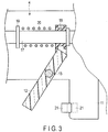
- FIG. 3 is a view showing an internal configuration of the housing 4.
- a movable 17 extends along the longitudinal axis C in the interior of the housing 4.
- the movable member 17 is movable along the longitudinal axis C relative to the housing 4.
- the movable member 17 is coupled to at least one of the first and second grasping pieces 13 and 14 via a movable pipe (not shown) extending along the longitudinal axis C in the interior of the sheath 5.
- a movable pipe not shown
- the movable member 17 is provided with a protruding section 19 that protrudes toward the outer side thereof.
- a slide member 18 is disposed away from the protruding section 19 toward the proximal side.
- a coil spring 20 of an elastic member is provided between the protruding section 19 and the slide member 18.
- the proximal end of the coil spring 20 is connected to the slide member 18 and the distal end thereof is connected to the protruding section 19.
- the length of the coil spring 20 is L0 in its natural state. When no treatment target is placed between the grasping pieces 13 and 14, the coil spring 20 is attached in a reference state where it is contracted by displacement amount x0 from the natural state. In this instance, if the elastic coefficient of the coil spring 20 is k0, elastic force k0 ⁇ 0 is exerted on the movable member 17 from the coil spring 20.
- the handle 12 is coupled to the slide member 18.
- the handle 12 is also coupled to the housing 4 via a fulcrum pin 15.
- the handle 12 revolves on the fulcrum pin 15 relative to the housing 4 and opens or closes relative to the grip 11.
- the grip 11 is provided with an abutting member 21. When the handle 12 closes relative to the grip 11, the handle 12 abuts on the abutting member 21.
- a surgeon holds the grip 11 and presses the handle 12 toward the grip 11. Then, the surgeon operates to close the handle 12 relative to the grip 11 until the handle 12 abuts on the abutting member 21 of the grip 11. Accordingly, the handle 12 revolves on the fulcrum pin 15 and simultaneously the slide member 18, movable member 17 and movable pipe (not shown) move integrally to the distal side along the longitudinal direction. Thus, at least one of the grasping pieces 13 and 14 operates to close relative to the other. In other words, the end effector 6 operates to close.
- the coil spring 20 is not contracted from a reference state, and the elastic force that is exerted on the movable member 17 from the coil spring 20 does not vary from k0 ⁇ 0.
- the end effector 6 stops operating to close.
- the movable pipe and the movable member 17 thus stop moving to the distal side. If the handle 12 is operated to close relative to the grip 11 until the handle 12 abuts on the abutting member 21 of the grip 11 from this state, the slide member 18 moves to the distal side relative to the movable member 17. When the slide member 18 moves to the distal side relative to the movable member 17, the coil spring 20 is contracted further from the reference state.
- the elastic force that is exerted on the movable member 17 from the coil spring 20 when the coil spring 20 is contracted further from the reference state is k0(x0+x), which is larger than the elastic force k0 ⁇ 0 in the reference state.
- the grasping force applied to the treatment target to be grasped between the first and second grasping pieces 13 and 14 increases in comparison with the case where the coil spring 20 is in the reference state.
- the grasping force applied to the treatment target to be grasped between the paired grasping pieces 13 and 14 is determined in accordance with the displacement amount (contraction amount) x by which the coil spring 20 is contracted.
- the grasping force adjustment unit 41 adjusts the grasping force applied to the treatment target to be grasped between the grasping pieces 13 and 14.
- the foregoing abutting member 21 provided at the grip 11 corresponds to the grasping force adjustment unit 41.
- the abutting member 21 drives the driving member 42 (see FIG. 2 ) provided in the interior of the housing 4 to move in the longitudinal direction relative to the grip 11.
- the driving member 42 for example, an electric motor is used.
- the selection unit 44 such as a lever can be attached to the housing 4 and operated manually to move the abutting member 21 in the longitudinal direction relative to the grip 11.
- the movement amount (stroke) by which the handle 12 moves until the handle 12 abuts on the abutting member 21 varies.
- the movement amount by which the slide member 18 coupled to the handle 12 moves in the longitudinal direction relative to the movable member 17 varies.
- the displacement amount (contraction amount) of the coil spring 20 varies.
- the grasping force applied to the treatment target is determined by the displacement amount of the coil spring 20. The grasping force applied to the treatment target can thus be varied by varying the position of the abutting member 21.
- the coil spring 20 is contracted by displacement amount x1 from the reference state with the handle 12 abutting on the abutting member 21.
- the elastic force k0(x0+x1) is exerted on the movable member 17 from the coil spring 20, and the grasping force to grasp a blood vessel between the grasping pieces 13 and 14 is a first grasping force.
- the abutting member 21 is located in a second position (indicated by the broken line in FIG.
- the coil spring 20 is contracted by displacement amount x2 that is larger than the amount x1 from the reference state with the handle 12 abutting on the abutting member 21.
- the elastic force k0(x0+x2) which is larger than the elastic force k0(x0+x1), is exerted on the movable member 17 from the coil spring 20, and the grasping force to grasp a blood vessel between the grasping pieces 13 and 14 is a second grasping force that is larger than the first grasping force.
- the driving member 42 or the selection unit 44 varies the position of the abutting member 21 that is the grasping force adjustment unit 41 to vary the grasping force to be applied to the treatment target.
- FIG. 4 is a view showing an internal configuration of the housing 4 according to the present modification.
- a ring-like member 19a is provided on the outer side of the movable member 17 along the circumferential direction of the movable member 17 (axial rotation direction).
- One end (distal end) of the coil spring 20 is connected to the ring-like member 19a.
- the ring-like member 19a has an inclined surface 25 that inclines toward the inner side in the distal side direction.
- the rod-like member 22 abuts on the ring-like member 19a from its distal side.
- the driving member 42 (see FIG. 2 ) is provided in the interior of the housing 4, and the rod-like member 22 is moved in the radial direction of the ring-like member 19a by driving the driving member 42.
- the rod-like member 22 abuts on the inclined surface 25 to regulate the movement of the ring-like member 19a to the distal side.
- the driving member 42 for example, an electric motor is used.
- the selection unit 44 such as a lever can be attached to the housing 4 and operated manually to move the rod-like member 22 in the radial direction of the ring-like member 19a.
- the displacement amount (contraction amount) x0 from the natural state varies in a state where no treatment target is interposed between the grasping pieces 13 and 14 (namely, a reference state), in accordance with the position of the rod-like member 22 in its radial direction.
- a reference state a state where no treatment target is interposed between the grasping pieces 13 and 14
- the coil spring 20 is contracted by the displacement amount xa0 from the natural state in the reference state. Accordingly, in the reference state, the elastic force k0xa0 is exerted on the movable member 17 from the coil spring 20.
- the coil spring 20 When the rod-like member 22 is located in the second position, the coil spring 20 is contracted by the displacement amount xb0, which is larger than the displacement amount xa0, from the natural state in the reference state. Thus, the elastic force k0 ⁇ b0 that is larger than the elastic force k0 ⁇ a0 is exerted on the movable member 17 from the coil spring 20 in the reference state. When the coil spring 20 is contracted further from the reference state, the elastic force k0(xb0+x), which is larger than the elastic force k0(xa0+x), is exerted on the movable member 17 from the coil spring 20.
- the grasping force to be applied to the treatment target becomes larger than that in the case where the rod-like member 22 is located in the first position.
- the grasping force to grasp a blood vessel between the grasping pieces 13 and 14 is a first grasping force when the rod-like member 22 is located in the first position
- the grasping force to grasp a blood vessel between the grasping pieces 13 and 14 is a second grasping force that is larger than the first grasping force when the rod-like member 22 is located in the second position.
- the rod-like member 22 corresponds to the grasping force adjustment unit 41, and the driving member 42 or the selection unit 44 move the rod-like member 22 in the radial direction of the ring-like member 19a to allow the grasping force applied to the treatment target to vary.
- a bar member 23 and a stopper 24 can be provided as the grasping force adjustment unit 41.
- FIG. 5 is a view showing the interior of the sheath 5 and a configuration of the end effector 6 according to the present modification. As shown in FIG.
- the end effector 6 includes a first grasping piece 13 provided at a distal portion of the rod member 16 inserted through the sheath 5 and a second grasping piece 14 revolvably coupled to a distal portion of the sheath 5.
- the bar member 23 extends along the longitudinal direction in the interior of the sheath 5.
- the bar member 23 is provided on the side opposite to the first opposing surface 31 with respect to the longitudinal axis C.
- the driving member 42 (see FIG. 2 ) is provided in the interior of the housing 4 and driven to move the bar member 23 in the longitudinal direction relative to the rod member 16.
- the driving member 42 for example, an electric motor is used.
- the selection unit 44 such as a lever can be attached to the housing 4 and operated manually to move the bar member 23 in the longitudinal direction relative to the rod member 16.
- the stopper 24, which abuts on the outer surface of the rod member 16, is provided at a distal portion of the bar member 23.
- the stopper 24 is formed of, e.g. polytetrafluoroethylene (PTFE) that is excellent in abrasion resistance.
- PTFE polytetrafluoroethylene
- the stopper 24 is disposed between the rod member 16 and the sheath 5. In a position where the stopper 24 abuts on the rod member 16, the rod member 16 is supported in the open direction of the second grasping piece 14. In the position where the stopper 24 abuts on the rod member 16, the rod member 16 is prevented from bending in the close direction of the second grasping piece 14.
- the first grasping piece 13 and the rod member 16 receive pressure force from the second grasping piece 14 in the close direction of the second grasping piece 14. Then, the rod member 16 is bent (curved) toward the close direction of the second grasping piece 14 from a position in which the rod member 16 is supported by the stopper 24 to the distal end of the rod member 16. In other words, a portion from a position in which the rod member 16 is supported by the stopper 24 to the distal end of the rod member 16 is bent by the pressure force in the close direction of the second grasping piece 14.
- the grasping force applied to the treatment target to be grasped between the first and second grasping pieces 13 and 14 varies with the amount of bent of the first grasping piece 13 in the close direction of the second grasping piece 14.
- the bar member 23 and the stopper 24 correspond to the grasping force adjustment unit 41.
- the bar member 23 and the stopper 24 move integrally in the longitudinal direction relative to the rod member 16 to vary a position in which the rod member 16 is supported by the stopper 24.
- the length from the position in which the rod member 16 is supported by the stopper 24 to the distal end of the rod member 16 varies, as does the amount of bent of the first grasping piece 13 in the close direction of the second grasping piece 14.
- the stopper 24 is located in a first position (indicated by the solid line in FIG.
- the rod member 16 has a first length from the position in which the rod member 16 is supported by the stopper 24 to the distal end of the rod member 16, and the amount of bent of the first grasping piece 13 in the close direction of the second grasping piece 14 is a first amount of bent.
- the stopper 24 is located in a second position (indicated by the broken line in FIG. 5 ) which is closer to the distal side than the first position, the length from the position in which the rod member 16 is supported by the stopper 24 to the distal end of the rod member 16 is a second length that is smaller than the first length.
- the amount of bent of the first grasping piece 13 in the close direction of the second grasping piece 14 is a second amount of bent which is smaller than the first amount of bent.
- the grasping force applied to the treatment target to be grasped between the first and second grasping pieces 13 and 14 becomes smaller than that in the case where the stopper 24 is located in the first position.
- the grasping force to grasp a blood vessel between the first and second grasping pieces 13 and 14 corresponds to a first grasping force when the stopper 24 is located in the first position
- the grasping force to grasp a blood vessel between the first and second grasping pieces 13 and 14 corresponds to a second grasping force that is larger than the first grasping force when the stopper 24 is located in the second position.
- the bar member 23 and the stopper 24 correspond to the grasping force adjustment unit 41, and the driving member 42 or the selection unit 44 move the bar member 23 and the stopper 24 in the longitudinal direction relative to the rod member 16 to allow the grasping force applied to the treatment target to vary.
- FIG. 6 is a cross-sectional view showing an end effector 6 according to the present modification, which is substantially parallel to the longitudinal axis C.
- a proximal end portion of the first grasping piece is coupled to the driving member 42 (see FIG. 2 ), and the driving member 42 is driven to rotate the first grasping piece 13 in the axial rotation direction of the longitudinal axis C relative to the second grasping piece 14.
- the first grasping piece rotates in the axial rotation direction of the longitudinal axis C relative to the second grasping piece 14 a surface that is to be the first opposing surface 31 opposed to the second opposing surface 32 is selected, and the first grasping piece 13 varies in its thickness in the open and close direction of the first grasping piece 13.
- the driving member 42 for example, an electric motor is used.
- the selection unit 44 such as a lever can be attached to the housing 4 and operated manually to rotate the first grasping piece 13 in the axial rotation direction of the longitudinal axis C relative to the second grasping piece 14.
- the first grasping piece 13 When the second grasping piece 14 is closed relative to the first grasping piece 13, the first grasping piece 13 receives pressure force from the second grasping piece 14 in the close direction of the second grasping piece 14. Then, the first grasping piece 13 is bent (curved) toward the close direction of the second grasping piece 14. The amount of bent of the first grasping piece 13 toward the close direction of the second grasping piece 14 varies with the thickness of the first grasping piece 13 in the open and close direction of the second grasping piece 14. The grasping force applied to the treatment target to be grasped between the first and second grasping pieces 13 and 14 varies with the amount of bent of the first grasping piece 13 in the close direction of the second grasping piece 14.
- the first grasping piece 13 corresponds to the grasping force adjustment unit 41.
- the first grasping piece 13 rotates in the axial rotation direction of the longitudinal axis C relative to the second grasping piece 14 a surface that is opposed to the second opposing surface 32 as the first opposing surface 31 is selected.
- the first grasping piece 13 varies in its thickness in the open and close direction of the second grasping piece 14.
- the first grasping piece 13 varies in its bent amount in the close direction of the second grasping piece 14.
- the amount of bent of the first grasping piece 13 in the close direction of the second grasping piece 14 is a first amount of bent.
- the thickness of the first grasping piece 13 in the open and close direction of the second grasping piece 14 is a second thickness (indicated by the broken line in FIG. 6 ) that is larger than the first thickness
- the amount of bent of the first grasping piece 13 in the close direction of the second grasping piece 14 is a second amount of bent that is smaller than the first amount of bent.
- the grasping force applied to the treatment target to be grasped between the first and second grasping pieces 13 and 14 becomes larger than that in the case where the thickness of the first grasping piece 13 in the open and close direction of the second grasping piece 14 is the first thickness.
- the grasping force to grasp a blood vessel between the first and second grasping pieces 13 and 14 corresponds to a first grasping force when the thickness of the first grasping piece 13 in the open and close direction of the second grasping piece 14 is the first thickness
- the grasping force to grasp a blood vessel between the first and second grasping pieces 13 and 14 corresponds to a second grasping force that is larger than the first grasping force when the thickness of the first grasping piece 13 in the open and close direction of the second grasping piece 14 is the second thickness.
- the first grasping piece 13 corresponds to the grasping force adjustment unit 41, and the driving member 42 or the selection unit 44 move the first grasping piece 13 in the axial rotation direction of the longitudinal axis C relative to the second grasping piece 14 to allow the grasping force applied to the treatment target to vary.
- the housing 4 may include, as the grasping force adjustment unit 41 (see FIG. 2 ), a ratchet (not shown) that have a plurality of groove portions (not shown) and a claw portion (not shown) extending to the groove portions of the ratchet from the handle 12.
- the groove portions in which the claw portion is fit when the handle 12 operates to close relative to the grip 11 are formed along the longitudinal direction in the interior of the housing 4.
- the handle 12 closes relative to the grip 11 the handle 12 moves to the proximal side along the longitudinal direction.
- the claw portion is fit into one of the groove portions.
- the handle 12 operates to close further relative to the grip 11 from this state, it moves to the proximal side further along the longitudinal direction.
- the claw portion is fit into another one of the groove portions.
- a groove portion in which the claw portion is fit is changed to another by selecting a position to which the handle 12 moves.
- the claw portion corresponds to the grasping force adjustment unit 41. If a groove portion in which the claw portion is fit when the handle 12 closes relative to the grip 11 is changed to another, the movement amount (stroke) by which the handle 12 moves when the handle 12 closes relative to the grip 11 varies. If the movement amount (stroke) by which the handle 12 moves when the handle 12 closes relative to the grip 11 varies, the movement amount by which the slide member 18 coupled to the handle 12 moves in the longitudinal direction relative to the movable member 17 varies. If the movement amount by which the slide member 18 moves relative to the movable member 17 varies, the displacement amount (contraction amount) of the coil spring 20 varies.
- the grasping force applied to a treatment target is determined in accordance with the displacement amount (contraction amount) of the coil spring 20.
- the grasping force applied to a treatment target can thus be varied by changing a groove portion in which the claw portion is fit. For example, when the claw portion of the handle 12 is fit in a first groove portion that is one of the groove portions, the movement amount by which the handle 12 operates to close corresponds to a first movement amount. Accordingly, the coil spring 20 contracts by displacement amount x1 from the reference state. Elastic force k0(x0+x1) is thus exerted on the movable member 17 from the coil spring 20, and the grasping force to grasp a blood vessel between the grasping pieces 13 and 14 is a first grasping force.
- the movement amount by which the handle 12 operates to close corresponds to a second movement amount that is larger than the first movement amount.
- the coil spring 20 contracts by displacement amount x2, which is larger than displacement amount x1, from the reference state.
- Elastic force k0(x0+x2) which is larger than elastic force k0(x0+x1), is thus exerted on the movable member 17 from the coil spring 20, and the grasping force to grasp a blood vessel between the grasping pieces 13 and 14 is a second grasping force that is larger than the first grasping force.
- the grasping force applied to the treatment target is varied by changing a groove portion in which the claw portion corresponding to the grasping force adjustment unit 41 is changed to another by operating the handle 12 serving as the selection unit 44.
- the grasping force adjustment unit has only to be configured to vary the grasping force to be applied to a treatment target (blood vessel) in accordance with an actuation state.
- the detector 43 detects information (parameter) about a blood vessel to be grasped between the grasping pieces 13 and 14.
- information parameter
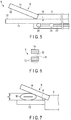
- FIG. 7 is a view showing the end effector 6 and a blood vessel M which is to be grasped between the grasping pieces 13 and 14 and which is contracted to some extent in the open and close direction of the end effector 6. As shown in FIG.
- the dimension H of the blood vessel M in the open and close direction of the end effector 6 when the blood vessel M to be grasped is contracted to some extent in the open and close direction of the end effector 6, is substantially proportionate to the wall thickness T of the blood vessel.
- the angle ⁇ of the second grasping piece to the first grasping piece 13 is proportionate to the dimension H of the blood vessel M grasped between the first and second grasping pieces 13 and 14 in the open and close direction of the end effector 6. Therefore, when the blood vessel M to be grasped is contracted to some extent in the open and close direction of the end effector 6, the angle ⁇ of the second grasping piece to the first grasping piece 13 is substantially proportionate to the wall thickness T of the blood vessel M.
- a pressure sensor 34 is provided as the detector 43 at a proximal portion of the second opposing surface 32.
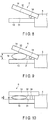
- FIG. 8 is a view showing the end effector 6 according to a certain example. As shown in FIG. 8 , in the present example, the pressure sensor 34 protrudes in the close direction of the second grasping piece 14 on the second opposing surface 32.
- the pressure sensor 34 is electrically connected to the processor 47 of the energy controller 3 via an electrical circuit (not shown) which is formed in the interior of the energy treatment instrument 2.
- the pressure sensor 34 receives pressure force from the first opposing surface 31.
- pressure P received by the pressure sensor 34 becomes higher than that in the case where the pressure sensor 34 does not abut on the first opposing surface 31.
- FIGS. 9 and 10 are views each showing the end effector 6 and the blood vessel M contracted to some extent in the open and close direction of the end effector 6.
- the blood vessels M shown in FIGS. 9 and 10 are different in wall thickness T.
- the wall thickness T of the blood vessel M to be grasped is larger than a predetermined thickness Tth, the dimension H increases with the blood vessel M contracted to some extent in the open and close direction of the end effector 6.
- the pressure sensor 34 is not brought into contact with the first opposing surface 31, but the pressure received by the pressure sensor 34 decreases.
- a sensing signal indicating a sensing result in the pressure sensor 34 is input to the setting unit 51 of the processor 47.
- information of the pressure received by the pressure sensor 34 is input to the setting unit 51 as information regarding the blood vessel M.
- the setting unit 51 determines that the pressure P received by the pressure sensor 34 is smaller than a threshold value Pth.
- a threshold value Pth As described above, when the wall thickness T of the blood vessel M is large, the dimension H increases with the blood vessel M contracted to some extent in the open and close direction of the end effector 6, and the pressure P received by the pressure sensor 34 decreases.
- the setting unit 51 determines that the pressure P is smaller than the threshold value Pth, it determines that the wall thickness T of the blood vessel M to be grasped is larger than the predetermined thickness Tth.
- the setting unit 51 may determine the blood vessel M to be grasped as a blood vessel of a systemic circulatory system with a relatively large wall thickness T.
- the dimension H decreases with the blood vessel M contracted to some extent in the open and close direction of the end effector 6. Accordingly, the pressure sensor 34 abuts on the first opposing surface 31 and the pressure received by the pressure sensor 34 increases.
- a sensing signal indicating a sensing result (information regarding the blood vessel M) in the pressure sensor 34 is input to the setting unit 51.
- the setting unit 51 determines that the pressure P received by the pressure sensor 34 is equal to or larger than the threshold value Pth.
- the setting unit 51 determines that the pressure P is equal to or larger than the threshold value Pth, it determines that the wall thickness T of the blood vessel M to be grasped is equal to or smaller than the predetermined thickness Tth.
- the setting unit 51 may determine the blood vessel M to be grasped as a blood vessel of a pulmonary circulatory system with a relatively small wall thickness T.
- the pressure sensor 34 senses the pressure P received by the pressure sensor 34 as information (parameter) regarding the blood vessel M. Furthermore, based on the sensing signal from the pressure sensor 34, the setting unit 51 can obtain information regarding the wall thickness T of the blood vessel M. Then, based on the information regarding the blood vessel M (information of the pressure received by the pressure sensor 34), which is input to the setting unit 51, the setting unit 51 sets information regarding the wall thickness T such as whether the wall thickness T of the blood vessel M is larger than the predetermined thickness Tth, or a type of the blood vessel M (a systemic circulatory system or a pulmonary circulatory system). In other words, in the present modification, the pressure sensor 34 corresponds to the detector 43 to sense information regarding the blood vessel M to be grasped.
- the pressure sensor 34 can be provided at each of the proximal and distal portions of the second opposing surface 32.
- the pressure sensor 34 can also be provided at the proximal portion of the first opposing surface 31.
- one or more pressure sensors 34 have only to be provided on at least one of the first and second opposing surfaces 31 and 32.
- FIGS. 11 and 12 are views each showing an end effector 6 and a blood vessel M contracted to some extent in the open and close direction of the end effector 6 in the present modification.
- the blood vessels M shown in FIGS. 11 and 12 are different in wall thickness T.
- the first conductive member 35 is provided at the proximal portion of the first opposing surface 31 to protrude in the close direction of the first grasping piece 13.
- the second conductive member 36 is opposed to the first conductive member 35 and provided at the proximal portion of the second opposing surface 32 to protrude in the close direction of the second grasping piece 14.
- the first and second conductive members 35 and 36 are supplied with electrical energy, which is different from electrical energy to be converted into driving power and treatment energy, from the power supply unit 46 of the energy controller 3.
- electrical energy which is different from electrical energy to be converted into driving power and treatment energy
- the foregoing dimension H increases and thus the first and second conductive members 35 and 36 are not brought into contact with each other. For this reason, no current flows through an electrical circuit that is routed through the first conductive member 35, second conductive member 36 and power supply unit 46.
- the setting unit 51 determines that the wall thickness T of the blood vessel M is larger than the predetermined thickness Tth or determines that the blood vessel M to be grasped is a blood vessel of a systemic circulatory system with a relatively large wall thickness T.
- the wall thickness T of the blood vessel M is relatively small (e.g. when it is equal to or smaller than the predetermined thickness Tth)
- the dimension H decreases and thus the first and second conductive members are brought into contact with each other. For this reason, current flows through the electrical circuit that is routed through the first conductive member, second conductive member and power supply unit 46.
- the setting unit 51 determines that the wall thickness T of the blood vessel M is equal to or smaller than the predetermined thickness Tth or determines that the blood vessel M to be grasped is a blood vessel of a pulmonary circulatory system with a relatively small wall thickness T.
- the first and second conductive members 35 and 36 of the detector 43 detect, as information regarding the blood vessel M, whether current flows through the electrical circuit that is routed through the first conductive member 35, second conductive member 36 and power supply unit 46.
- the setting unit 51 sets information regarding the wall thickness T such as whether the wall thickness T of the blood vessel M is larger than the predetermined thickness Tth, or a type of the blood vessel M (a systemic circulatory system or a pulmonary circulatory system).
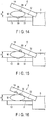
- an angle sensor 37 can be provided as the detector 43, as shown in FIG. 13.
- FIG. 13 is a view showing an end effector 6 and a blood vessel M according to the present modification, with the blood vessel M, which is grasped between the grasping pieces 13 and 14, contracted to some extent in the open and close direction of the end effector 6.
- the angle sensor 37 is provided in a coupling section between the second grasping piece 14 and the sheath 5.
- the angle sensor 37 senses angle ⁇ between the first grasping piece 13 and the second grasping piece.
- an encoder or a potentiometer is used as the angle sensor 37.
- the angle sensor 37 is electrically connected to the processor 47 of the energy controller 3 via a signal path (not shown) formed in the interior of the energy treatment instrument 2.
- the angle sensor 37 of the detector 43 is used when the blood vessel M grasped between the grasping pieces 13 and 14 is contracted to some extent in the open and close direction of the end effector 6. For example, when the wall thickness T of the blood vessel M to be grasped is larger than the predetermined thickness Tth, the angle ⁇ between the first and second grasping pieces 13 and 14 increases.
- a sensing signal indicating a sensing result of the angle sensor 37 is input to the setting unit 51 of the processor 47. In this instance, the angle ⁇ between the first and second grasping pieces 13 and 14 is input to the setting unit 51 as information regarding the blood vessel M.
- the setting unit 51 determines that the angle ⁇ between the first and second grasping pieces 13 and 14 is larger than a threshold value ⁇ th.
- a threshold value ⁇ th As described above, when the wall thickness T of the blood vessel M is large, the angle ⁇ between the first and second grasping pieces 13 and 14 increases.
- the setting unit 51 determines that the angle ⁇ between the first and second grasping pieces 13 and 14 is larger than the threshold value ⁇ th, it determines that the wall thickness T of the blood vessel M to be grasped is larger than the predetermined thickness Tth. In this instance, the setting unit 51 may determine the blood vessel M to be grasped as a blood vessel of a systemic circulatory system with a relatively large wall thickness T.
- the angle ⁇ between the first grasping piece 13 and the second grasping piece decreases.
- a sensing signal indicating a sensing result of the angle sensor 37 (information regarding the blood vessel M) is input to the setting unit 51.
- the setting unit 51 determines that the angle ⁇ between the first and second grasping pieces 13 and 14 is equal to or smaller than the threshold value ⁇ th.
- the angle ⁇ between the first and second grasping pieces 13 and 14 decreases.
- the setting unit 51 determines that the angle ⁇ between the first and second grasping pieces 13 and 14 is equal to or smaller than the threshold value ⁇ th, it determines that the wall thickness T of the blood vessel M to be grasped is equal to or smaller than the predetermined thickness Tth.
- the setting unit 51 may determine the blood vessel M to be grasped as a blood vessel of a pulmonary circulatory system with a relatively small wall thickness T.
- the angle sensor 34 senses the angle ⁇ between the first and second grasping pieces 13 and 14 as information (parameter) regarding the blood vessel M. Furthermore, based on the sensing signal from the angle sensor 37, the setting unit 51 can obtain information regarding the wall thickness T of the blood vessel M. Then, based on the information regarding the blood vessel M (information of the angle ⁇ between the first and second grasping pieces 13 and 14), which is input to the setting unit 51, the setting unit 51 sets information regarding the wall thickness T such as whether the wall thickness T of the blood vessel M is larger than the predetermined thickness Tth, or a type of the blood vessel M (a systemic circulatory system or a pulmonary circulatory system). In other words, in the present modification, the angle sensor 37 corresponds to the detector 43 to sense information regarding the blood vessel M to be grasped.
- FIG. 14 is a view showing an end effector 6 and a blood vessel M according to the present modification, with the blood vessel M, which is grasped between the grasping pieces 13 and 14, contracted to some extent in the open and close direction of the end effector 6.
- a light-emitting element 38 such as an LED is provided on the second opposing surface 32.
- a light-receiving element 39 such as a PD is provided on the first opposing surface 31.
- the light-receiving element 39 is electrically connected to the processor 47 of the energy controller 3 via a signal path (not shown) formed in the interior of the energy treatment instrument 2.
- the light-emitting element 38 Upon receiving electrical energy, which is different from electrical energy to be converted into driving power and treatment energy, from the energy controller 3, the light-emitting element 38 emits light to the light-receiving element 39.
- the light-receiving element 39 detects an amount of light (light intensity) Q incident upon the light-receiving element 39.
- the detector 43 is used with the blood vessel M grasped between the grasping pieces 13 and 14 contracted to some extent in the open and close direction of the end effector 6.
- the light-emitting element 38 emits light to the blood vessel M and the light-receiving element 39. Part of the light emitted to the blood vessel M is reflected or absorbed by blood vessel tissue in the interior of the blood vessel M. Of the light emitted to the blood vessel M, light (transmitted light) that is neither reflected nor absorbed by the blood vessel tissue enters the light-receiving element 39. Then, the light-receiving element 39 detects the light amount Q of transmitted light.
- the dimension H increases with the blood vessel M contracted to some extent in the open and close direction of the end effector 6. Accordingly, of the light emitted to the blood vessel M, light reflected or absorbed by the blood vessel tissue increases in amount. The amount of light reflected or absorbed by the blood vessel tissue increases, the light amount Q of transmitted light that enters the light-receiving element 39 decreases.
- a detection signal indicating a detection result in the light-receiving element 39 is input to the setting unit 51 of the processor 47.
- the setting unit 51 determines that the light amount Q of transmitted light that enters the light-receiving element 39 is smaller than a threshold value Qth.
- a threshold value Qth As described above, when the wall thickness T of the blood vessel M is large, the foregoing dimension H increases and the light amount Q of transmitted light that enters the light-receiving element 39 decreases.
- the setting unit 51 determines that the light amount Q is smaller than the threshold value Qth, it determines that the wall thickness T of the blood vessel M to be grasped is larger than the predetermined thickness Tth.
- the setting unit 51 may determine the blood vessel M to be grasped as a blood vessel of a systemic circulatory system with a relatively large wall thickness T.
- the dimension H decreases with the blood vessel M contracted to some extent in the open and close direction of the end effector 6. Accordingly, of the light emitted to the blood vessel M, light reflected or absorbed by the blood vessel tissue decreases in amount. When the amount of light reflected or absorbed by the blood vessel tissue decreases, the light amount Q of transmitted light that enters the light-receiving element 39 increases.
- a detection signal indicating a detection result in the light-receiving element 39 is input to the setting unit 51 of the processor 47.
- information of the light amount Q of transmitted light that enters the light-receiving element 39 as information regarding the blood vessel M is input to the setting unit 51.
- the setting unit 51 determines that the light amount Q of transmitted light that enters the light-receiving element 39 is larger than the threshold value Qth.
- the foregoing dimension H decreases and the light amount Q of transmitted light that enters the light-receiving element 39 increases.
- the setting unit 51 determines that the light amount Q of transmitted light that enters the light-receiving element 39 is equal to or larger than the threshold value Qth, it determines that the wall thickness T of the blood vessel M to be grasped is equal to or smaller than the predetermined thickness Tth.
- the setting unit 51 may determine the blood vessel M to be grasped as a blood vessel of a pulmonary circulatory system with a relatively small wall thickness T.
- the light-receiving element 39 detects the light amount Q of transmitted light that enters the light-receiving element 39 as information (parameter) regarding the blood vessel M. Furthermore, based on the detection signal from the light-receiving element 39, the setting unit 51 can obtain information regarding the wall thickness T of the blood vessel M. Then, based on the information regarding the blood vessel M (information of the light amount Q of transmitted light that enters the light-receiving element 39), which is input to the setting unit 51, the setting unit 51 sets information regarding the wall thickness T such as whether the wall thickness T of the blood vessel M is larger than the predetermined thickness Tth, or a type of the blood vessel M (a systemic circulatory system or a pulmonary circulatory system). In other words, in the present modification, the light-receiving element 39 corresponds to the detector 43 to detect information regarding the blood vessel M to be grasped.
- the light-emitting element 38 is provided on the second opposing surface 32 and the light-receiving element 39 is provided on the first opposing surface 31, which is, however, not restrictive.
- the light-emitting element 38 can be provided on the first opposing surface 31 and the light-receiving element 39 can be provided on the second opposing surface 32.
- both the light-emitting element 38 and the light-receiving element 39 can be provided on the second opposing surface 32.
- the light-receiving element 39 detects the amount of light that is reflected by the first opposing surface 31 and then enters the light-receiving element 39.
- both the light-emitting element 38 and the light-receiving element 39 can be provided on the first opposing surface 31.
- the information regarding the blood vessel used in the present modification is not limited to the amount of light.
- ultrasound can be provided as a certain modification.
- ultrasonic diagnostic equipment (not shown) is provided as the detector 43.
- an ultrasonic emission unit (not shown) and an ultrasonic reception unit (not shown) are provided.
- the ultrasonic emission unit emits ultrasound to the blood vessel M and the ultrasonic reception unit detects ultrasound that is transmitted through the blood vessel M. Then, information of the emitted ultrasound and information of the detected ultrasound are input to the setting unit 51 of the processor 47.
- the setting unit 51 visualizes the interior of the blood vessel M using a time difference between time when ultrasound is emitted and time when ultrasound is detected. Then, based on an image of the visualized interior of the blood vessel M, the setting unit 51 determines that the wall thickness T of the blood vessel M to be grasped is larger than the predetermined thickness Tth (or equal to or smaller than the predetermined thickness Tth). In this instance, the setting unit 51 may determine the blood vessel M to be grasped as a blood vessel of a systemic circulatory system with a relatively large wall thickness T (or a blood vessel of a pulmonary circulatory system with a relatively small wall thickness T).
- the detector 43 can be provided in the interior of the housing 4 and configured to detect a displacement amount (contraction amount) x by which the coil spring 20 is contracted from the reference state, with the blood vessel M to be grasped contracted to some extent in the open and close direction of the end effector 6.
- a detection signal indicating a detection result in the detector 43 is input to the setting unit 51 of the processor 47.
- the foregoing displacement amount (contraction amount) x by which the coil spring 20 is contracted from the reference state is input to the setting unit 51 as information regarding the blood vessel M.
- the displacement amount (contraction amount) x by which the coil spring 20 is contracted from the reference state varies with the foregoing dimension H with the blood vessel M to be grasped contracted to some extent in the open and close direction of the end effector 6.
- the dimension H is substantially proportionate to the wall thickness T of the blood vessel M.
- the setting unit 51 determines that the wall thickness T of the blood vessel M to be grasped is larger than the predetermined thickness Tth (or equal to or smaller than the predetermined thickness Tth). In this instance, the setting unit 51 may determine the blood vessel M to be grasped as a blood vessel of a systemic circulatory system with a relatively large wall thickness T (or a blood vessel of a pulmonary circulatory system with a relatively small wall thickness T).
- an electrical circuit (not shown) that is routed through the power supply unit 46 and electrodes (not shown) provided in their respective first and second grasping pieces 13 and 14, can be provide as the detector 43.
- the electrodes are provided in their respective first and second grasping pieces 13 and 14 and supplied with electrical energy (high-frequency power) from the power supply unit 46 of the energy controller 3.
- high-frequency current flows through the blood vessel between the electrodes.
- high-frequency current When high-frequency current is used as treatment energy, high-frequency current is supplied to a blood vessel to be grasped as treatment energy through the first opposing surface 31 of the first grasping piece 13 and the second opposing surface 32 of the second grasping piece 14, which are energy application sections.
- high-frequency current When high-frequency current is not supplied to the blood vessel as treatment energy, high-frequency current flows through the blood vessel to such a degree that the blood vessel to be grasped is not degenerated. Then, the foregoing electrical circuit detects the high-frequency current flowing through the blood vessel.
- the detector 43 is used with the blood vessel M grasped between the grasping pieces 13 and 14 contracted to some extent in the open and close direction of the end effector 6.
- an electrical circuit is formed to be routed through the electrodes provided in their respective grasping pieces 13 and 14, the blood vessel M and the power supply unit 46.
- the power supply unit 46 supplies electrical energy (high-frequency power) to the foregoing electrical circuit, high-frequency current flows into the electrical circuit through the blood vessel M.
- the current flowing into the electrical circuit through the blood vessel M is input to the setting unit 51 as information regarding the blood vessel. For example, when the wall thickness T of the blood vessel M to be grasped is larger than the predetermined thickness Tth, the dimension H increases with the blood vessel M contracted to some extent in the open and close direction of the end effector 6.
- the setting unit 51 calculates impedance Z of the blood vessel M and determines that the impedance Z of the blood vessel M is smaller than a threshold value Zth based on the calculation result.
- the impedance Z of the blood vessel M decreases with the blood vessel M contracted to some extent in the open and close direction of the end effector 6.
- the setting unit 51 determines that the impedance Z is smaller than the threshold value Zth, it determines that the wall thickness T of the blood vessel M to be grasped is larger than the predetermined thickness Tth.
- the setting unit 51 may determine the blood vessel M to be grasped as a blood vessel of a systemic circulatory system with a relatively large wall thickness T.
- the foregoing dimension H decreases. Accordingly, water contained in the section of the blood vessel M in the open and close direction of the end effector 6 decreases. As described above, it is known that the electrical resistance of water is low. The less the water contained in the section of the blood vessel M in the open and close direction of the end effector 6, the higher the impedance Z (electrical resistance) of the blood vessel M. When the water contained in the section of the blood vessel M in the open and close direction of the end effector 6 decreases, the impedance Z (electrical resistance) of the blood vessel M heightens.
- the setting unit 51 calculates impedance Z of the blood vessel M and determines that the impedance Z of the blood vessel M is equal to or higher than the threshold value Zth based on the calculation result.
- the impedance Z of the blood vessel M increases with the blood vessel M contracted to some extent in the open and close direction of the end effector 6.
- the setting unit 51 determines that the impedance Z is equal to or higher than the threshold value Zth, it determines that the wall thickness T of the blood vessel M to be grasped is equal to or smaller than the predetermined thickness Tth.
- the setting unit 51 may determine the blood vessel M to be grasped as a blood vessel of a pulmonary circulatory system with a relatively small wall thickness T.
- the characteristics of high-frequency current flowing through the blood vessel M to be grasped are detected as information (parameter) regarding the blood vessel M, using an electrical circuit that is routed through the power supply unit 46 and the electrodes provided in their respective first and second grasping pieces 13 and 14. Furthermore, based on a detection signal indicating the foregoing characteristics of high-frequency current, the setting unit 51 can obtain information regarding the wall thickness T of the blood vessel M.
- the setting unit 51 sets information regarding the wall thickness T such as whether the wall thickness T of the blood vessel M is larger than the predetermined thickness Tth, or a type of the blood vessel M (a systemic circulatory system or a pulmonary circulatory system).
- the electrodes provided in their respective first and second grasping pieces 13 and 14 correspond to the detector 43 to detect information regarding the blood vessel M to be grasped.
- FIG. 17 is a view showing a structure of a heart 100 and its neighborhood.
- the heart 100 includes a left atrium 101, a left ventricle 102, a right atrium 103 and a right ventricle 104.
- the pulmonary vein 105 extends from the left atrium 101 and the main artery 106 extends from the left ventricle 102.
- the main vein 107 extends from the right atrium 103 and the pulmonary artery 108 extends from the right ventricle 104.
- a circulatory pathway that guides blood from the left ventricle 102 to the whole body through the main artery 106 and returns the blood from the whole body to the right atrium 103 through the main vein 107 is referred to as systemic circulation.
- a circulatory pathway that guides blood from the right ventricle 104 to the lungs through the pulmonary artery 108 and returns the blood from the lungs to the left atrium 101 through the pulmonary vein 105 is referred to as pulmonary circulation.
- the end effector 6 is inserted into a chest cavity and moved until the blood vessel is located between the first and second grasping pieces 13 and 14. Then, the handle 12 is closed relative to the grip 11 with the blood vessel to be treated between the first and second grasping pieces 13 and 14.
- the handle 12 is closed relative to the grip 11 with the blood vessel to be treated between the first and second grasping pieces 13 and 14.
- the blood vessel is contracted to some extent in the open and close direction of the end effector 6.
- the first and second grasping pieces 13 and 14 are closed relative to each other to grasp the blood vessel.
- the running direction of the blood vessel crosses the longitudinal direction and the open and close direction of each of the first and second grasping pieces 13 and 14.
- At least one of ultrasonic vibration, high-frequency current, heat and the like is applied to the blood vessel to cut the blood vessel open and simultaneously seal (coagulate) it as described above.
- the wall thickness T of blood vessels of pulmonary circulation is considered to be smaller than that of blood vessels of systemic circulation.
- the number of biopolymers gelatinized in sealing treatment (bonding treatment) on the section of a blood vessel of pulmonary circulation, which is perpendicular to the extending direction of the biopolymers is smaller than that on the section of a blood vessel of systemic circulation, the sections having the same diameter. Therefore, when a blood vessel of pulmonary circulation and a blood vessel of systemic circulation are treated, if the same grasping force is exerted on both the blood vessels, it is likely to have an influence upon the treatment performance.
- the drive controller 52 determines a parameter regarding the grasping force exerted on a treatment target to be grasped between the grasping pieces 13 and 14.
- the drive controller 52 determines that a first grasping force is exerted on the blood vessel to be grasped between the grasping pieces. Based on the determination, the drive controller 52 controls driving power to be applied to the driving member 42 from the driving power output unit 50. Accordingly, the driving of the driving member 42 is controlled, as is the actuation of the grasping force adjustment unit 41. When the actuation of the grasping force adjustment unit 41 is controlled, the first grasping force is exerted on the blood vessel grasped between the grasping pieces 13 and 14.
- the drive controller 52 determines to exert the second grasping force, which is larger than the first grasping force, on a treatment target to be grasped between the grasping pieces 13 and 14. Based on the determination, the drive controller 52 controls the driving power to be supplied to the driving member 42 from the driving power output unit 50. Accordingly, the driving of the driving member 42 is controlled, as is the actuation of the grasping force adjustment unit 41. When the actuation of the grasping force adjustment unit 41 is controlled, the second grasping force is exerted on the blood vessel grasped between the grasping pieces 13 and 14.
- the grasping force adjustment unit 41 adjusts the grasping force to grasp a blood vessel between the first and second grasping pieces 13 and 14 to the first grasping force when the wall thickness T set by the setting unit 51 is larger than the predetermined thickness Tth, and adjusts the grasping force to grasp a blood vessel between the first and second grasping pieces 13 and 14 to the second grasping force, which is larger than the first grasping force, when the wall thickness T set by the setting unit 51 is equal to or smaller than the predetermined thickness Tth.
- the information regarding the wall thickness T of the blood vessel (information indicating whether the wall thickness T is larger than the predetermined thickness Tth and/or information indicating a type of the blood vessel) set by the setting unit 51 of the processor 47 can be notified to a surgeon by, e.g. a notification unit (not shown) provided in the energy controller 3 or the like.
- the surgeon manually operates the selection unit 44 (see FIG. 2 ) attached to, e.g. the housing 4 to adjust the actuation state of the grasping force adjustment unit 41. Accordingly, the grasping force exerted on the blood vessel between the grasping pieces 13 and 14 is adjusted.
- the selection unit 44 is operated to adjust the grasping force to grasp the blood vessel between the first and second grasping pieces 13 and 14 to the first grasping force.
- the selection unit 44 is operated to adjust the grasping force to grasp the blood vessel between the first and second grasping pieces 13 and 14 to the second grasping force which is larger than the first grasping force.
- the information input unit 53 provided in the energy controller 3 can be operated to input information regarding a blood vessel.
- the setting unit 51 sets information regarding the wall thickness T of the blood vessel to be grasped based on an input result in the information input unit 53 (information regarding the blood vessel input to the information input unit 53).
- the drive controller 52 controls the actuation of the grasping force adjustment unit 41 or the surgeon manually operates the selection unit 44 to adjust the grasping force exerted on the blood vessel between the grasping pieces 13 and 14.
- FIGS. 18 and 19 are sectional views showing the end effector 6 and the blood vessel M, which are substantially perpendicularly to the width direction of the end effector 6 when the first grasping force and the second grasping force are exerted on the blood vessel M grasped between the grasping pieces 13 and 14.
- FIG. 18 when the first grasping force is exerted on the blood vessel M, the upper and lower inner walls of the blood vessel M come close to each other and the distance between the upper and lower inner walls of the blood vessel M is a first distance ⁇ 1.
- FIG. 18 shows that when the first grasping force is exerted on the blood vessel M, the upper and lower inner walls of the blood vessel M come close to each other and the distance between the upper and lower inner walls of the blood vessel M is a first distance ⁇ 1.
- FIG. 18 when the first grasping force is exerted on the blood vessel M, the upper and lower inner walls of the blood vessel M come close to each other and the distance between the upper and lower inner walls of the blood vessel M is a first distance ⁇ 1.
- the second grasping force which is larger than the first grasping force
- the upper and lower inner walls of the blood vessel M further come close to each other and the distance between the upper and lower inner walls of the blood vessel M is a second distance ⁇ 2 that is smaller than the first distance ⁇ 1.
- the second distance ⁇ 2 is zero or very close to zero.
- the second distance ⁇ 2 is smaller than the first distance ⁇ 1.
- the number of biopolymers gelatinized in a grasping region between the grasping pieces 13 and 14 becomes larger than that in the case where the first grasping force is exerted on the blood vessel. Since, therefore, even a blood vessel whose wall thickness T is small, such as a blood vessel of a pulmonary circulatory system, is grasped with a large grasping force (e.g.
- the degree of adhesion between the upper and lower inner walls of the blood vessel M is secured in sealing treatment, as is the number of biopolymers gelatinized in a grasping region between the grasping pieces 13 and 14
- sealing performance is secured in sealing treatment, and treatment performance is secured in treatment to cut a blood vessel open and simultaneously coagulate it.
- the energy surgical instrument 1 can be provided which is suitable for treatment to seal (and simultaneously coagulate) a blood vessel whose wall thickness T is small such as a blood vessel of a pulmonary circulatory system.
- the energy surgical instrument 1 can be provided which can exercise appropriate treatment performance even though blood vessels which differ in wall thickness T, such as a blood vessel of a pulmonary circulatory system and a blood vessel of a systemic circulatory system that differ in wall thickness T, are sealed.
- a blood vessel is sealed using high-frequency energy, the following additional advantageous effects are produced.
- electrodes (not shown) are provided in their respective first and second grasping pieces 13 and 14 and supplied with electrical energy (high-frequency power) from the power supply unit 46 of the energy controller 3.
- a high-frequency current is supplied as treatment energy to the blood vessel M to be grasped between the grasping pieces 13 and 14, through the first and second opposing surfaces 31 and 32, which are energy application sections.
- the blood vessel M is contracted to some extent in the open and close direction of the grasping pieces 13 and 14.
- the first and second grasping pieces 13 and 14 close relative to each other, and the distance between the first and second opposing surfaces 31 and 32 (distance between the electrodes) is a first distance N1.
- the second grasping force which is larger than the first grasping force, is exerted on the blood vessel M as shown in FIG. 19 , the blood vessel M is contracted further in the open and close direction of the grasping pieces 13 and 14.
- the first and second grasping pieces 13 and 14 close further relative to each other, and the distance between the first and second opposing surfaces 31 and 32 (distance between the electrodes) is a second distance N2 that is smaller than the first distance N1.
- the current density of the high-frequency current flowing between the electrodes is in inverse proportion to the distance between the electrodes (distance between the first and second opposing surfaces 31 and 32).
- the energy surgical instrument (1) includes a first grasping piece (13) and a second grasping piece (14) which can be opened and closed relative to each other, a blood vessel being grasped between the first grasping piece (13) and the second grasping piece (14) when the first grasping piece (13) and the second grasping piece are closed relative to each other.
- At least one of the first grasping piece (13) and the second grasping piece (14) is provided with an energy application section (31; 32; 31, 32) which applies treatment energy to the blood vessel grasped between the first grasping piece (13) and the second grasping piece (14) to treat the blood vessel.
- the energy surgical instrument (1) also includes a setting unit 51 that sets information regarding the wall thickness T of a blood vessel and a grasping force adjustment unit (41) which adjusts a grasping force to grasp the blood vessel between the first grasping piece (13) and the second grasping piece (14) to a first grasping force when the wall thickness T set by the setting unit 51 is larger than a predetermined thickness Tth and adjusts the grasping force to a second grasping piece, which is larger than the first grasping force, when the wall thickness T set by the setting unit 51 is equal to or smaller than the predetermined thickness Tth.
- a grasping force adjustment unit (41) which adjusts a grasping force to grasp the blood vessel between the first grasping piece (13) and the second grasping piece (14) to a first grasping force when the wall thickness T set by the setting unit 51 is larger than a predetermined thickness Tth and adjusts the grasping force to a second grasping piece, which is larger than the first grasping force, when the wall thickness T set by the setting unit 51 is equal to or smaller than the pre
- a treatment method comprising:
Landscapes
- Health & Medical Sciences (AREA)
- Surgery (AREA)
- Life Sciences & Earth Sciences (AREA)
- Engineering & Computer Science (AREA)
- Molecular Biology (AREA)
- Public Health (AREA)
- Heart & Thoracic Surgery (AREA)
- Medical Informatics (AREA)
- Nuclear Medicine, Radiotherapy & Molecular Imaging (AREA)
- Animal Behavior & Ethology (AREA)
- General Health & Medical Sciences (AREA)
- Biomedical Technology (AREA)
- Veterinary Medicine (AREA)
- Physics & Mathematics (AREA)
- Plasma & Fusion (AREA)
- Otolaryngology (AREA)
- Dentistry (AREA)
- Mechanical Engineering (AREA)
- Surgical Instruments (AREA)
Abstract
Description
- The present invention relates to an energy surgical instrument which grasps a treatment target such as living tissue between a pair of grasping pieces to conduct treatment using treatment energy such as an ultrasonic vibration and a high-frequency current.
-
Patent literature 1 discloses an energy surgical instrument which grasps a treatment target such as living tissue between a pair of grasping pieces and applies treatment energy to the grasped treatment target to allow the treatment target to be sealed. - Patent literature 1:
U.S. Patent Application Publication No. 2011/0118736 - Blood vessels to be treated may vary in wall thickness according to position, type and the like. In surgery, blood vessels that differ in wall thickness may be sealed (coagulated) with an energy surgical instrument that is similar to that of
patent literature 1. In this treatment, if the blood vessels are grasped with the same grasping force, it may affect the sealing performance of the blood vessels. - The present invention has been made to solve the foregoing problem and its object is to provide an energy surgical instrument capable of achieving treatment performance as appropriate even though blood vessels are different in wall thickness.
- To solve the above mentioned problems, according to one aspect of the invention, an energy surgical instrument includes a first grasping piece, a second grasping piece which is allowed to open and close relative to the first grasping piece and which is allowed to grasp a blood vessel between the first grasping piece and the second grasping piece, an energy application unit provided in at least one of the first grasping piece and the second grasping piece, which applies treatment energy to the blood vessel grasped between the first grasping piece and the second grasping piece to treat the blood vessel, a setting unit which sets information regarding a wall thickness of the blood vessel, and a grasping force adjustment unit which adjusts a grasping force to grasp the blood vessel between the first grasping piece and the second grasping piece to a first grasping force when the wall thickness set by the setting unit is larger than a predetermined thickness and adjusting the grasping force to a second grasping force, which is larger than the first grasping force, when the wall thickness set by the setting unit is equal to or smaller than the predetermined thickness.
- According to the present invention, there can be provided an energy surgical instrument capable of achieving treatment performance as appropriate even though blood vessels are different in wall thickness.
-
-
FIG. 1 is a schematic view showing an outward appearance of an energy surgical instrument according to a first embodiment. -
FIG. 2 is a block diagram schematically showing an actuation configuration and a control configuration of the energy surgical instrument according to the first embodiment. -
FIG. 3 is a schematic view showing an internal configuration of a housing according to the first embodiment. -
FIG. 4 is a schematic view showing an internal configuration of a housing according to a first modification. -
FIG. 5 is a schematic view showing the interior of a sheath and a configuration of an end effector according to a second modification. -
FIG. 6 is a schematic cross-sectional view showing an end effector according to a third modification, which is substantially perpendicular to a longitudinal axis thereof. -
FIG. 7 is a schematic view showing an end effector according to the first embodiment, by which a blood vessel is grasped. -
FIG. 8 is a schematic view showing a configuration of the end effector according to the first embodiment. -
FIG. 9 is a schematic view showing the end effector according to the first embodiment, by which a blood vessel whose wall thickness is larger than a predetermined thickness is grasped. -
FIG. 10 is a schematic view showing the end effector according to the first embodiment, by which a blood vessel whose wall thickness is smaller than a predetermined thickness is grasped. -
FIG. 11 is a schematic view showing an end effector according to a fourth modification, by which a blood vessel whose wall thickness is larger than a predetermined thickness is grasped. -
FIG. 12 is a schematic view showing the end effector according to the fourth modification, by which a blood vessel whose wall thickness is smaller than a predetermined thickness is grasped. -
FIG. 13 is a schematic view schematically showing a configuration of an end effector according to a fifth modification. -
FIG. 14 is a schematic view schematically showing a configuration of an end effector according to a sixth modification. -
FIG. 15 is a schematic view schematically showing a configuration of an end effector according to a seventh modification. -
FIG. 16 is a schematic view schematically showing a configuration of an end effector according to an eighth modification. -
FIG. 17 is a schematic view showing a structure of a heart and its neighborhood. -
FIG. 18 is a schematic view showing the end effector according to the first embodiment, by which a blood vessel is grasped with a first grasping force. -
FIG. 19 is a schematic view showing the end effector according to the first embodiment, by which a blood vessel is grasped with a second grasping force. - Embodiments and the like of the present invention will be described below with reference to
FIGS. 1-19 .FIG. 1 is a view showing an outward appearance of an energy surgical instrument (treatment system) 1 according to a first embodiment. As shown inFIG. 1 , the energysurgical instrument 1 includes anenergy treatment instrument 2 and anenergy controller 3. Theenergy treatment instrument 2 has a longitudinal axis C. Here, one side of the direction along the longitudinal axis C is defined as a distal side (arrow C1 side) and the side opposite to the distal side is defined as a proximal side (arrow C2 side). The direction that is parallel to the longitudinal axis C is defined as a longitudinal direction. - The
energy treatment instrument 2 includes aholdable housing 4. Asheath 5 extends along the longitudinal axis C and is inserted into thehousing 4 from the distal side. The central axis of thesheath 5 is substantially aligned with the longitudinal axis C. Anend effector 6 is provided at a distal portion of thesheath 5. One end of acable 7 is connected to thehousing 4. The other end of thecable 7 is separably connected to theenergy controller 3. - The
housing 4 includes agrip 11. Ahandle 12 is revolvably attached to thehousing 4. Thehandle 12 revolves relative to thehousing 4 and thus opens or closes relative to thegrip 11. In the present embodiment, thehandle 12 is located on the distal side of thegrip 11, which is, however, not restrictive. In a certain modification, for example, thehandle 12 may be located on the proximal side of thegrip 11. Furthermore, in the present embodiment, thehandle 12 can open and close in a direction substantially parallel to the longitudinal axis C relative to thegrip 11, which is, however, not restrictive. In another certain example, thehandle 12 may open and close in a direction substantially perpendicularly to the longitudinal axis C relative to thegrip 11. - The
end effector 6 includes afirst grasping piece 13 and asecond grasping piece 14 which can open and close relative to thefirst grasping piece 13. Thefirst grasping piece 13 has a firstopposing surface 31 opposed to thesecond grasping piece 14. Thesecond grasping piece 14 has a secondopposing surface 32 opposed to the first grasping piece 13 (first opposing surface 31). Thehandle 12 opens or closes relative to thegrip 11 and accordingly the pairedgrasping pieces grasping pieces second grasping pieces grasping pieces end effector 6 is defined as a width direction of the end effector 6 (first andsecond grasping pieces 13 and 14). - The
end effector 6 has only to be so configured that a treatment target can be grasped between thegrasping pieces second grasping pieces sheath 5 along the longitudinal axis C and a protruding portion that protrudes toward the distal side from the distal end of thesheath 5. The other of the first andsecond grasping pieces sheath 5. In another certain example, one of the first andsecond grasping pieces sheath 5. The other of the first andsecond grasping pieces sheath 5. In still another certain example, both of the first and second graspingpieces sheath 5. -
FIG. 2 is a block diagram schematically showing an actuation configuration and a control configuration of the energysurgical instrument 1. As shown inFIG. 2 , theenergy treatment instrument 2 includes a graspingforce adjustment unit 41 that adjusts grasping force to be applied to a treatment target grasped between the graspingpieces member 42 such as an electric motor. The actuation state of the graspingforce adjustment unit 41 varies with the driving state of the drivingmember 42. Theend effector 6 also includes adetector 43 that detects information about a blood vessel grasped between the graspingpieces force adjustment unit 41 and thedetector 43 will be described in detail later. - The
energy controller 3 includes apower supply unit 46, a processor (or an integrated circuit, etc.) 47 with a central processing unit (CPU), an application specific integrated circuit (ASIC) or the like and astorage medium 48 such as a memory. Thepower supply unit 46 includes apower supply 49 such as a battery and an outlet and a drivingpower output unit 50 that outputs driving power to the drivingmember 42. The drivingpower output unit 50 includes, e.g. a conversion circuit that converts power from thepower supply 49 into driving power and supplies the driving power to the drivingmember 42. - The
processor 47 includes asetting unit 51 and adrive controller 52. The settingunit 51 and drivecontroller 52 perform part of the process to be performed by theprocessor 47. The settingunit 51 sets information about wall thickness T of a blood vessel to be grasped, based upon information (parameter) about a blood vessel detected by thedetector 43. In this instance, the settingunit 51 may set wall thickness T of the blood vessel itself and set whether the wall thickness T of the blood vessel is greater than a predetermined thickness Tth. The settingunit 51 may also set a type of the blood vessel (a systemic circulatory system or a pulmonary circulatory system). Note that the predetermined thickness Tth is stored in thestorage medium 48, etc. In a certain example, furthermore, theenergy controller 3 is provided with a notification unit (not shown) such as a display and a buzzer, and the notification unit may notify the information about the wall thickness T of the blood vessel set by the settingunit 51. - In accordance with the information about the wall thickness T set by the setting
unit 51, thedrive controller 52 determines a parameter regarding the grasping force applied to a treatment target grasped between the graspingpieces drive controller 52 controls the supply of driving power to the drivingmember 42 from the drivingpower output unit 50. Accordingly, the driving of the drivingmember 42 is controlled, as is the actuation of the graspingforce adjustment unit 41. When the actuation of the graspingforce adjustment unit 41 is controlled, the grasping force applied to the treatment target between the graspingpieces - In the present embodiment, the
detector 43 detects information about a blood vessel to be grasped between the graspingpieces energy controller 3 can be provided with aninformation input unit 53 such as an operating panel to input information about a blood vessel manually. In this case, a surgeon operates theinformation input unit 53 to input information about a blood vessel. Thus, the settingunit 51 sets information about wall thickness T of a blood vessel to be grasped, based upon an input result of the information input unit 53 (information about a blood vessel input to the information input unit 53). - In the present embodiment, in accordance with the information about wall thickness T set by the setting
unit 51, theprocessor 47 controls the actuation of the graspingforce adjustment unit 41 to adjust the grasping force applied to the blood vessel between the graspingpieces housing 4 of theenergy treatment instrument 2 can be provided with aselection unit 44 such as a lever to select an actuation state of the graspingforce adjustment unit 41 manually. In this case, in accordance with the information about wall thickness T of a blood vessel set by the settingunit 51, the surgeon operates theselection unit 44 to adjust the actuation state of the graspingforce adjustment unit 41. Accordingly, the grasping force to be applied to the blood vessel between the graspingpieces - Furthermore, when a treatment target is grasped between the first and second grasping
pieces surfaces surfaces pieces pieces - An
operational button 33 is attached to thehousing 4 as an energy operation input section. Thepower supply unit 46 of theenergy controller 3 is provided with an energy output unit (not shown) which outputs electrical energy other than the driving power to theenergy treatment instrument 2. The energy output unit includes, e.g. a conversion circuit that converts power from thepower supply 49 into electrical energy and supplies the electrical energy to theenergy treatment instrument 2. Upon detecting operation input of theoperation button 33, theprocessor 47 causes thepower supply unit 46 to output the foregoing electrical energy to theenergy treatment instrument 2. - Note that the energy operation input section to perform an operation of outputting electrical energy from the
energy controller 3 is not limited to theoperation button 33. In a certain example, in place of theoperation button 33 or in addition to theoperation button 33, for example, a foot switch separate from theenergy treatment instrument 2 can be provided as the energy operation input section. In the present embodiment, furthermore, the electrical energy output from the energy output unit of thepower supply unit 46 can be directly applied to a blood vessel to be grasped as treatment energy, and the foregoing electrical energy can be converted into treatment energy such as an ultrasonic vibration and the treatment energy can be applied to a treatment target. - In a certain example, an ultrasonic vibration is applied to a treatment target as treatment energy. In this instance, an ultrasonic transducer (not shown) is provided in the interior of the
housing 4 and a rod member (not shown) is inserted through thesheath 5 as a vibration transmission member. In the interior of thehousing 4, the rod member is connected to the distal side of the ultrasonic transducer and accordingly, the first graspingpiece 13 is formed by a portion of the rod member protruding from thesheath 5 toward the distal side. In this example, when the electrical energy (AC power) output from thepower supply unit 46 of theenergy controller 3 is supplied to the ultrasonic transducer, the ultrasonic transducer generates an ultrasonic vibration. The generated ultrasonic vibration is transmitted from the proximal side to the distal side of the rod member (vibration transmission member) to vibrate the rod member including the first graspingpiece 13. When the rod member is vibrated with the treatment target grasped between the first and second graspingpieces piece 13. In this instance, the vibration causes frictional heat between the treatment target to be grasped and the first graspingpiece 13, and the treatment target is cut open and sealed (coagulated) simultaneously. - In another certain example, a high-frequency current is supplied to a treatment target as treatment energy. In this case, the first and second grasping
pieces power supply unit 46 of theenergy controller 3. When the electrical energy is applied to the electrodes with the treatment target grasped between the first and second graspingpieces surfaces pieces surfaces - In a certain example, the first and second grasping
pieces - In another certain example, at least one of the first and second grasping
pieces power supply unit 46 of theenergy controller 3, the heating element generates heat. When the heating element generates heat with a treatment target grasped between the first and second graspingpieces - Some of the treatment energies such as the ultrasonic vibration, high-frequency current and heat generated from the heating element can be applied simultaneously to a treatment target to be grasped. In a certain example, the ultrasonic vibration and high-frequency current are applied as treatment energy to a treatment target simultaneously. In this case, when electrical energy is supplied to the foregoing ultrasonic transducer from the
power supply unit 46 of theenergy controller 3, an ultrasonic vibration is generated and simultaneously electrical energy is supplied to the electrodes of the first and second graspingpieces power supply unit 46 of theenergy controller 3. In another certain example, the high-frequency current as treatment energy and heat generated from the heating element as treatment energy are supplied to a treatment target simultaneously. In this case, when electrical energy is supplied to the foregoing heating element from thepower supply unit 46 of theenergy controller 3, heat is generated and simultaneously electrical energy is supplied to the electrodes of the first and second graspingpieces power supply unit 46 of theenergy controller 3. - Next, the grasping
force adjustment unit 41 will be described.FIG. 3 is a view showing an internal configuration of thehousing 4. As shown inFIG. 3 , a movable 17 extends along the longitudinal axis C in the interior of thehousing 4. Themovable member 17 is movable along the longitudinal axis C relative to thehousing 4. Themovable member 17 is coupled to at least one of the first and second graspingpieces sheath 5. For example, in a certain example, when themovable member 17 moves to the distal side relative to thehousing 4, at least one of the first and second graspingpieces movable member 17 moves the proximal side relative to thehousing 4, at least one of the first and second graspingpieces movable member 17 moves along the longitudinal axis C relative to thehousing 4 and thesheath 5, the paired graspingpieces - The
movable member 17 is provided with a protrudingsection 19 that protrudes toward the outer side thereof. On the outer side of themovable member 17, aslide member 18 is disposed away from the protrudingsection 19 toward the proximal side. Between the protrudingsection 19 and theslide member 18, acoil spring 20 of an elastic member is provided. The proximal end of thecoil spring 20 is connected to theslide member 18 and the distal end thereof is connected to the protrudingsection 19. The length of thecoil spring 20 is L0 in its natural state. When no treatment target is placed between the graspingpieces coil spring 20 is attached in a reference state where it is contracted by displacement amount x0 from the natural state. In this instance, if the elastic coefficient of thecoil spring 20 is k0, elastic force k0×0 is exerted on themovable member 17 from thecoil spring 20. - The
handle 12 is coupled to theslide member 18. Thehandle 12 is also coupled to thehousing 4 via afulcrum pin 15. Thehandle 12 revolves on thefulcrum pin 15 relative to thehousing 4 and opens or closes relative to thegrip 11. Thegrip 11 is provided with an abuttingmember 21. When thehandle 12 closes relative to thegrip 11, thehandle 12 abuts on the abuttingmember 21. - To grasp a treatment target between the grasping
pieces grip 11 and presses thehandle 12 toward thegrip 11. Then, the surgeon operates to close thehandle 12 relative to thegrip 11 until thehandle 12 abuts on the abuttingmember 21 of thegrip 11. Accordingly, thehandle 12 revolves on thefulcrum pin 15 and simultaneously theslide member 18,movable member 17 and movable pipe (not shown) move integrally to the distal side along the longitudinal direction. Thus, at least one of the graspingpieces end effector 6 operates to close. Until a treatment target to be grasped is contracted to some extent in the open and close direction of theend effector 6, thecoil spring 20 is not contracted from a reference state, and the elastic force that is exerted on themovable member 17 from thecoil spring 20 does not vary from k0×0. - When the treatment target to be grasped is contracted to some extent in the open and close direction of the
end effector 6, theend effector 6 stops operating to close. The movable pipe and themovable member 17 thus stop moving to the distal side. If thehandle 12 is operated to close relative to thegrip 11 until thehandle 12 abuts on the abuttingmember 21 of thegrip 11 from this state, theslide member 18 moves to the distal side relative to themovable member 17. When theslide member 18 moves to the distal side relative to themovable member 17, thecoil spring 20 is contracted further from the reference state. If the displacement amount (contraction amount) of thecoil spring 20 from the reference state is x, the elastic force that is exerted on themovable member 17 from thecoil spring 20 when thecoil spring 20 is contracted further from the reference state is k0(x0+x), which is larger than the elastic force k0×0 in the reference state. When the elastic force k0(x0+x) that is larger than the elastic force k0×0 in the reference state is exerted on themovable member 17 from thecoil spring 20, the grasping force applied to the treatment target to be grasped between the first and second graspingpieces coil spring 20 is in the reference state. In other words, the grasping force applied to the treatment target to be grasped between the paired graspingpieces coil spring 20 is contracted. - The grasping
force adjustment unit 41 adjusts the grasping force applied to the treatment target to be grasped between the graspingpieces foregoing abutting member 21 provided at thegrip 11 corresponds to the graspingforce adjustment unit 41. The abuttingmember 21 drives the driving member 42 (seeFIG. 2 ) provided in the interior of thehousing 4 to move in the longitudinal direction relative to thegrip 11. As the drivingmember 42, for example, an electric motor is used. In another certain example, the selection unit 44 (seeFIG. 2 ) such as a lever can be attached to thehousing 4 and operated manually to move the abuttingmember 21 in the longitudinal direction relative to thegrip 11. - When the abutting
member 21 moves in the longitudinal direction relative to thegrip 11 and thus thehandle 12 operates to close relative to thegrip 11, the movement amount (stroke) by which thehandle 12 moves until thehandle 12 abuts on the abuttingmember 21 varies. Accordingly, the movement amount by which theslide member 18 coupled to thehandle 12 moves in the longitudinal direction relative to themovable member 17 varies. As the movement amount by which theslide member 18 moves relative to themovable member 17 varies, the displacement amount (contraction amount) of thecoil spring 20 varies. As describe above, the grasping force applied to the treatment target is determined by the displacement amount of thecoil spring 20. The grasping force applied to the treatment target can thus be varied by varying the position of the abuttingmember 21. For example, when the abuttingmember 21 is located in a first position (indicated by the solid line inFIG. 3 ), thecoil spring 20 is contracted by displacement amount x1 from the reference state with thehandle 12 abutting on the abuttingmember 21. Thus, the elastic force k0(x0+x1) is exerted on themovable member 17 from thecoil spring 20, and the grasping force to grasp a blood vessel between the graspingpieces member 21 is located in a second position (indicated by the broken line inFIG. 3 ) which is closer to the proximal side than the first position, thecoil spring 20 is contracted by displacement amount x2 that is larger than the amount x1 from the reference state with thehandle 12 abutting on the abuttingmember 21. Thus, the elastic force k0(x0+x2), which is larger than the elastic force k0(x0+x1), is exerted on themovable member 17 from thecoil spring 20, and the grasping force to grasp a blood vessel between the graspingpieces member 42 or theselection unit 44 varies the position of the abuttingmember 21 that is the graspingforce adjustment unit 41 to vary the grasping force to be applied to the treatment target. - Note that a rod-
like member 22 can be provided as the graspingforce adjustment unit 41 as shown inFIG. 4 as a first modification.FIG. 4 is a view showing an internal configuration of thehousing 4 according to the present modification. As shown inFIG. 4 , in the present modification, in place of the protrudingsection 19, a ring-like member 19a is provided on the outer side of themovable member 17 along the circumferential direction of the movable member 17 (axial rotation direction). One end (distal end) of thecoil spring 20 is connected to the ring-like member 19a. The ring-like member 19a has aninclined surface 25 that inclines toward the inner side in the distal side direction. The rod-like member 22 abuts on the ring-like member 19a from its distal side. In a certain example, the driving member 42 (seeFIG. 2 ) is provided in the interior of thehousing 4, and the rod-like member 22 is moved in the radial direction of the ring-like member 19a by driving the drivingmember 42. The rod-like member 22 abuts on theinclined surface 25 to regulate the movement of the ring-like member 19a to the distal side. As the drivingmember 42, for example, an electric motor is used. In another certain example, the selection unit 44 (seeFIG. 2 ) such as a lever can be attached to thehousing 4 and operated manually to move the rod-like member 22 in the radial direction of the ring-like member 19a. - In the
coil spring 20 of the present modification, the displacement amount (contraction amount) x0 from the natural state varies in a state where no treatment target is interposed between the graspingpieces 13 and 14 (namely, a reference state), in accordance with the position of the rod-like member 22 in its radial direction. For example, when the rod-like member 22 is located in a first position (indicated by the solid line inFIG. 4 ) of the ring-like member 19a, thecoil spring 20 is contracted by the displacement amount xa0 from the natural state in the reference state. Accordingly, in the reference state, the elastic force k0xa0 is exerted on themovable member 17 from thecoil spring 20. When thecoil spring 20 is contracted further from the reference state, the elastic force k0(xa0+x) is exerted on themovable member 17 from thecoil spring 20. When the rod-like member 22 is located in a second position (indicated by the broken line inFIG. 4 ) which is inside the first position in the radial direction of the ring-like member 19a, pressure force exerted on the ring-like member 19a from the rod-like member 22 becomes larger than that in the case where the rod-like member 22 is located in the first position. Therefore, when the rod-like member 22 is located in the second position, the ring-like member 19a is located on the proximal side as compared with the case where the rod-like member 22 is located in the first position. When the rod-like member 22 is located in the second position, thecoil spring 20 is contracted by the displacement amount xb0, which is larger than the displacement amount xa0, from the natural state in the reference state. Thus, the elastic force k0×b0 that is larger than the elastic force k0×a0 is exerted on themovable member 17 from thecoil spring 20 in the reference state. When thecoil spring 20 is contracted further from the reference state, the elastic force k0(xb0+x), which is larger than the elastic force k0(xa0+x), is exerted on themovable member 17 from thecoil spring 20. - Therefore, when the rod-
like member 22 is located in the second position, the grasping force to be applied to the treatment target becomes larger than that in the case where the rod-like member 22 is located in the first position. For example, the grasping force to grasp a blood vessel between the graspingpieces like member 22 is located in the first position, and the grasping force to grasp a blood vessel between the graspingpieces like member 22 is located in the second position. As described above, in the present modification, the rod-like member 22 corresponds to the graspingforce adjustment unit 41, and the drivingmember 42 or theselection unit 44 move the rod-like member 22 in the radial direction of the ring-like member 19a to allow the grasping force applied to the treatment target to vary. Furthermore, as shown inFIG. 5 as a second modification, abar member 23 and astopper 24 can be provided as the graspingforce adjustment unit 41.FIG. 5 is a view showing the interior of thesheath 5 and a configuration of theend effector 6 according to the present modification. As shown inFIG. 5 , in the present modification, theend effector 6 includes a firstgrasping piece 13 provided at a distal portion of therod member 16 inserted through thesheath 5 and a secondgrasping piece 14 revolvably coupled to a distal portion of thesheath 5. In other words, one of the paired graspingpieces bar member 23 extends along the longitudinal direction in the interior of thesheath 5. Thebar member 23 is provided on the side opposite to the first opposingsurface 31 with respect to the longitudinal axis C. In a certain example, the driving member 42 (seeFIG. 2 ) is provided in the interior of thehousing 4 and driven to move thebar member 23 in the longitudinal direction relative to therod member 16. As the drivingmember 42, for example, an electric motor is used. In another certain example, the selection unit 44 (seeFIG. 2 ) such as a lever can be attached to thehousing 4 and operated manually to move thebar member 23 in the longitudinal direction relative to therod member 16. Thestopper 24, which abuts on the outer surface of therod member 16, is provided at a distal portion of thebar member 23. Thestopper 24 is formed of, e.g. polytetrafluoroethylene (PTFE) that is excellent in abrasion resistance. Thestopper 24 is disposed between therod member 16 and thesheath 5. In a position where thestopper 24 abuts on therod member 16, therod member 16 is supported in the open direction of the secondgrasping piece 14. In the position where thestopper 24 abuts on therod member 16, therod member 16 is prevented from bending in the close direction of the secondgrasping piece 14. - When the second
grasping piece 14 is closed relative to the first graspingpiece 13, the first graspingpiece 13 and therod member 16 receive pressure force from the secondgrasping piece 14 in the close direction of the secondgrasping piece 14. Then, therod member 16 is bent (curved) toward the close direction of the secondgrasping piece 14 from a position in which therod member 16 is supported by thestopper 24 to the distal end of therod member 16. In other words, a portion from a position in which therod member 16 is supported by thestopper 24 to the distal end of therod member 16 is bent by the pressure force in the close direction of the secondgrasping piece 14. The grasping force applied to the treatment target to be grasped between the first and second graspingpieces piece 13 in the close direction of the secondgrasping piece 14. - In the present modification, the
bar member 23 and thestopper 24 correspond to the graspingforce adjustment unit 41. Thebar member 23 and thestopper 24 move integrally in the longitudinal direction relative to therod member 16 to vary a position in which therod member 16 is supported by thestopper 24. When a position in which therod member 16 is supported by thestopper 24 varies, the length from the position in which therod member 16 is supported by thestopper 24 to the distal end of therod member 16 varies, as does the amount of bent of the first graspingpiece 13 in the close direction of the secondgrasping piece 14. For example, when thestopper 24 is located in a first position (indicated by the solid line inFIG. 5 ), therod member 16 has a first length from the position in which therod member 16 is supported by thestopper 24 to the distal end of therod member 16, and the amount of bent of the first graspingpiece 13 in the close direction of the secondgrasping piece 14 is a first amount of bent. When thestopper 24 is located in a second position (indicated by the broken line inFIG. 5 ) which is closer to the distal side than the first position, the length from the position in which therod member 16 is supported by thestopper 24 to the distal end of therod member 16 is a second length that is smaller than the first length. The amount of bent of the first graspingpiece 13 in the close direction of the secondgrasping piece 14 is a second amount of bent which is smaller than the first amount of bent. - For this reason, when the
stopper 24 is located in the second position, the grasping force applied to the treatment target to be grasped between the first and second graspingpieces stopper 24 is located in the first position. For example, the grasping force to grasp a blood vessel between the first and second graspingpieces stopper 24 is located in the first position, and the grasping force to grasp a blood vessel between the first and second graspingpieces stopper 24 is located in the second position. As described above, in the present example, thebar member 23 and thestopper 24 correspond to the graspingforce adjustment unit 41, and the drivingmember 42 or theselection unit 44 move thebar member 23 and thestopper 24 in the longitudinal direction relative to therod member 16 to allow the grasping force applied to the treatment target to vary. - Furthermore, as shown in
FIG. 6 as a third modification, a firstgrasping piece 13, which can be rotated in the axial rotation direction of the longitudinal axis C relative to the graspingpiece 14, can be provided as the grasping force adjustment unit 41 (seeFIG. 2 ).FIG. 6 is a cross-sectional view showing anend effector 6 according to the present modification, which is substantially parallel to the longitudinal axis C. In the present modification, a proximal end portion of the first grasping piece is coupled to the driving member 42 (seeFIG. 2 ), and the drivingmember 42 is driven to rotate the first graspingpiece 13 in the axial rotation direction of the longitudinal axis C relative to the secondgrasping piece 14. When the first grasping piece rotates in the axial rotation direction of the longitudinal axis C relative to the secondgrasping piece 14, a surface that is to be the first opposingsurface 31 opposed to the second opposingsurface 32 is selected, and the first graspingpiece 13 varies in its thickness in the open and close direction of the first graspingpiece 13. As the drivingmember 42, for example, an electric motor is used. In another certain example, theselection unit 44 such as a lever can be attached to thehousing 4 and operated manually to rotate the first graspingpiece 13 in the axial rotation direction of the longitudinal axis C relative to the secondgrasping piece 14. - When the second
grasping piece 14 is closed relative to the first graspingpiece 13, the first graspingpiece 13 receives pressure force from the secondgrasping piece 14 in the close direction of the secondgrasping piece 14. Then, the first graspingpiece 13 is bent (curved) toward the close direction of the secondgrasping piece 14. The amount of bent of the first graspingpiece 13 toward the close direction of the secondgrasping piece 14 varies with the thickness of the first graspingpiece 13 in the open and close direction of the secondgrasping piece 14. The grasping force applied to the treatment target to be grasped between the first and second graspingpieces piece 13 in the close direction of the secondgrasping piece 14. - In the present modification, the first grasping
piece 13 corresponds to the graspingforce adjustment unit 41. When the first graspingpiece 13 rotates in the axial rotation direction of the longitudinal axis C relative to the secondgrasping piece 14, a surface that is opposed to the second opposingsurface 32 as the first opposingsurface 31 is selected. When a surface that is opposed to the second opposingsurface 32 as the first opposingsurface 31 is selected, the first graspingpiece 13 varies in its thickness in the open and close direction of the secondgrasping piece 14. When the first graspingpiece 13 varies in its thickness in the open and close direction of the secondgrasping piece 14, the first graspingpiece 13 varies in its bent amount in the close direction of the secondgrasping piece 14. For example, when the thickness of the first graspingpiece 13 in the open and close direction of the secondgrasping piece 14 is a first thickness (indicated by the solid line inFIG. 6 ), the amount of bent of the first graspingpiece 13 in the close direction of the secondgrasping piece 14 is a first amount of bent. When the thickness of the first graspingpiece 13 in the open and close direction of the secondgrasping piece 14 is a second thickness (indicated by the broken line inFIG. 6 ) that is larger than the first thickness, the amount of bent of the first graspingpiece 13 in the close direction of the secondgrasping piece 14 is a second amount of bent that is smaller than the first amount of bent. - For this reason, when the thickness of the first grasping
piece 13 in the open and close direction of the secondgrasping piece 14 is a second thickness, the grasping force applied to the treatment target to be grasped between the first and second graspingpieces piece 13 in the open and close direction of the secondgrasping piece 14 is the first thickness. For example, the grasping force to grasp a blood vessel between the first and second graspingpieces piece 13 in the open and close direction of the secondgrasping piece 14 is the first thickness, and the grasping force to grasp a blood vessel between the first and second graspingpieces piece 13 in the open and close direction of the secondgrasping piece 14 is the second thickness. As described above, in the present example, the first graspingpiece 13 corresponds to the graspingforce adjustment unit 41, and the drivingmember 42 or theselection unit 44 move the first graspingpiece 13 in the axial rotation direction of the longitudinal axis C relative to the secondgrasping piece 14 to allow the grasping force applied to the treatment target to vary. - In another certain modification, the
housing 4 may include, as the grasping force adjustment unit 41 (seeFIG. 2 ), a ratchet (not shown) that have a plurality of groove portions (not shown) and a claw portion (not shown) extending to the groove portions of the ratchet from thehandle 12. In this modification, the groove portions in which the claw portion is fit when thehandle 12 operates to close relative to thegrip 11, are formed along the longitudinal direction in the interior of thehousing 4. When thehandle 12 closes relative to thegrip 11, thehandle 12 moves to the proximal side along the longitudinal direction. In this instance, the claw portion is fit into one of the groove portions. When thehandle 12 operates to close further relative to thegrip 11 from this state, it moves to the proximal side further along the longitudinal direction. In this instance, the claw portion is fit into another one of the groove portions. In other words, when thehandle 12 closes relative to thegrip 11, a groove portion in which the claw portion is fit is changed to another by selecting a position to which thehandle 12 moves. - In the modification, the claw portion corresponds to the grasping
force adjustment unit 41. If a groove portion in which the claw portion is fit when thehandle 12 closes relative to thegrip 11 is changed to another, the movement amount (stroke) by which thehandle 12 moves when thehandle 12 closes relative to thegrip 11 varies. If the movement amount (stroke) by which thehandle 12 moves when thehandle 12 closes relative to thegrip 11 varies, the movement amount by which theslide member 18 coupled to thehandle 12 moves in the longitudinal direction relative to themovable member 17 varies. If the movement amount by which theslide member 18 moves relative to themovable member 17 varies, the displacement amount (contraction amount) of thecoil spring 20 varies. As described above, the grasping force applied to a treatment target is determined in accordance with the displacement amount (contraction amount) of thecoil spring 20. The grasping force applied to a treatment target can thus be varied by changing a groove portion in which the claw portion is fit. For example, when the claw portion of thehandle 12 is fit in a first groove portion that is one of the groove portions, the movement amount by which thehandle 12 operates to close corresponds to a first movement amount. Accordingly, thecoil spring 20 contracts by displacement amount x1 from the reference state. Elastic force k0(x0+x1) is thus exerted on themovable member 17 from thecoil spring 20, and the grasping force to grasp a blood vessel between the graspingpieces handle 12 is fit in a second groove portion of the groove portions, which is located closer to the proximal side than the first groove portion, the movement amount by which thehandle 12 operates to close corresponds to a second movement amount that is larger than the first movement amount. Accordingly, thecoil spring 20 contracts by displacement amount x2, which is larger than displacement amount x1, from the reference state. Elastic force k0(x0+x2), which is larger than elastic force k0(x0+x1), is thus exerted on themovable member 17 from thecoil spring 20, and the grasping force to grasp a blood vessel between the graspingpieces force adjustment unit 41 is changed to another by operating thehandle 12 serving as theselection unit 44. - As has been described as each of the modifications, the grasping force adjustment unit has only to be configured to vary the grasping force to be applied to a treatment target (blood vessel) in accordance with an actuation state.
- Next, the
detector 43 will be described. Thedetector 43 detects information (parameter) about a blood vessel to be grasped between the graspingpieces pieces pieces end effector 6.FIG. 7 is a view showing theend effector 6 and a blood vessel M which is to be grasped between the graspingpieces end effector 6. As shown inFIG. 7 , when the blood vessel M to be grasped is contracted to some extent in the open and close direction of theend effector 6, the upper and lower inner walls of the blood vessel M are brought into close contact with each other. Thus, the dimension H of the blood vessel M in the open and close direction of theend effector 6 when the blood vessel M to be grasped is contracted to some extent in the open and close direction of theend effector 6, is substantially proportionate to the wall thickness T of the blood vessel. When the grasped blood vessel M is contracted to some extent in the open and close direction of theend effector 6, the angle θ of the second grasping piece to the first graspingpiece 13 is proportionate to the dimension H of the blood vessel M grasped between the first and second graspingpieces end effector 6. Therefore, when the blood vessel M to be grasped is contracted to some extent in the open and close direction of theend effector 6, the angle θ of the second grasping piece to the first graspingpiece 13 is substantially proportionate to the wall thickness T of the blood vessel M. - In a certain example, a
pressure sensor 34 is provided as thedetector 43 at a proximal portion of the second opposingsurface 32.FIG. 8 is a view showing theend effector 6 according to a certain example. As shown inFIG. 8 , in the present example, thepressure sensor 34 protrudes in the close direction of the secondgrasping piece 14 on the second opposingsurface 32. Thepressure sensor 34 is electrically connected to theprocessor 47 of theenergy controller 3 via an electrical circuit (not shown) which is formed in the interior of theenergy treatment instrument 2. When thepressure sensor 34 abuts on the first opposingsurface 31, thepressure sensor 34 receives pressure force from the first opposingsurface 31. Thus, when thepressure sensor 34 abuts on the first opposingsurface 31, pressure P received by thepressure sensor 34 becomes higher than that in the case where thepressure sensor 34 does not abut on the first opposingsurface 31. - The
detector 43 is used with the blood vessel M grasped between the graspingpieces end effector 6.FIGS. 9 and 10 are views each showing theend effector 6 and the blood vessel M contracted to some extent in the open and close direction of theend effector 6. The blood vessels M shown inFIGS. 9 and 10 are different in wall thickness T. As shown inFIG. 9 , for example, when the wall thickness T of the blood vessel M to be grasped is larger than a predetermined thickness Tth, the dimension H increases with the blood vessel M contracted to some extent in the open and close direction of theend effector 6. Thus, thepressure sensor 34 is not brought into contact with the first opposingsurface 31, but the pressure received by thepressure sensor 34 decreases. A sensing signal indicating a sensing result in thepressure sensor 34 is input to thesetting unit 51 of theprocessor 47. In this instance, information of the pressure received by thepressure sensor 34 is input to thesetting unit 51 as information regarding the blood vessel M. In the state shown inFIG. 9 , based on the sensing signal from thepressure sensor 34, the settingunit 51 determines that the pressure P received by thepressure sensor 34 is smaller than a threshold value Pth. As described above, when the wall thickness T of the blood vessel M is large, the dimension H increases with the blood vessel M contracted to some extent in the open and close direction of theend effector 6, and the pressure P received by thepressure sensor 34 decreases. When thesetting unit 51 thus determines that the pressure P is smaller than the threshold value Pth, it determines that the wall thickness T of the blood vessel M to be grasped is larger than the predetermined thickness Tth. In this instance, the settingunit 51 may determine the blood vessel M to be grasped as a blood vessel of a systemic circulatory system with a relatively large wall thickness T. - Furthermore, as shown in
FIG. 10 , for example, when the wall thickness T of the blood vessel M to be grasped is less than the predetermined thickness Tth, the dimension H decreases with the blood vessel M contracted to some extent in the open and close direction of theend effector 6. Accordingly, thepressure sensor 34 abuts on the first opposingsurface 31 and the pressure received by thepressure sensor 34 increases. In the state shown inFIG. 10 , too, a sensing signal indicating a sensing result (information regarding the blood vessel M) in thepressure sensor 34 is input to thesetting unit 51. In the state shown inFIG. 10 , based on the sensing signal from thepressure sensor 34, the settingunit 51 determines that the pressure P received by thepressure sensor 34 is equal to or larger than the threshold value Pth. As described above, when the wall thickness T of the blood vessel M is small, the dimension H decreases with the blood vessel M contracted to some extent in the open and close direction of theend effector 6, and the pressure P received by thepressure sensor 34 increases. When thesetting unit 51 thus determines that the pressure P is equal to or larger than the threshold value Pth, it determines that the wall thickness T of the blood vessel M to be grasped is equal to or smaller than the predetermined thickness Tth. In this instance, the settingunit 51 may determine the blood vessel M to be grasped as a blood vessel of a pulmonary circulatory system with a relatively small wall thickness T. - As described above, in the present example, the
pressure sensor 34 senses the pressure P received by thepressure sensor 34 as information (parameter) regarding the blood vessel M. Furthermore, based on the sensing signal from thepressure sensor 34, the settingunit 51 can obtain information regarding the wall thickness T of the blood vessel M. Then, based on the information regarding the blood vessel M (information of the pressure received by the pressure sensor 34), which is input to thesetting unit 51, the settingunit 51 sets information regarding the wall thickness T such as whether the wall thickness T of the blood vessel M is larger than the predetermined thickness Tth, or a type of the blood vessel M (a systemic circulatory system or a pulmonary circulatory system). In other words, in the present modification, thepressure sensor 34 corresponds to thedetector 43 to sense information regarding the blood vessel M to be grasped. - Note in the present example that only one
pressure sensor 34 is provided on the second opposingsurface 32, which is, however, not restrictive. For example, thepressure sensor 34 can be provided at each of the proximal and distal portions of the second opposingsurface 32. Thepressure sensor 34 can also be provided at the proximal portion of the first opposingsurface 31. In other words, one ormore pressure sensors 34 have only to be provided on at least one of the first and second opposingsurfaces - As a fourth modification,
conductive members detector 43 in place of thepressure sensor 34.FIGS. 11 and 12 are views each showing anend effector 6 and a blood vessel M contracted to some extent in the open and close direction of theend effector 6 in the present modification. The blood vessels M shown inFIGS. 11 and 12 are different in wall thickness T. As shown inFIGS. 11 and 12 , in the present modification, the firstconductive member 35 is provided at the proximal portion of the first opposingsurface 31 to protrude in the close direction of the first graspingpiece 13. The secondconductive member 36 is opposed to the firstconductive member 35 and provided at the proximal portion of the second opposingsurface 32 to protrude in the close direction of the secondgrasping piece 14. The first and secondconductive members power supply unit 46 of theenergy controller 3. As shown inFIG. 11 , when the wall thickness T of the blood vessel M to be grasped is relatively large (e.g. when it is larger than the predetermined thickness Tth), the foregoing dimension H increases and thus the first and secondconductive members conductive member 35, secondconductive member 36 andpower supply unit 46. For example, based on that no current flows through the electrical circuit as described above, the settingunit 51 determines that the wall thickness T of the blood vessel M is larger than the predetermined thickness Tth or determines that the blood vessel M to be grasped is a blood vessel of a systemic circulatory system with a relatively large wall thickness T. On the other hand, when the wall thickness T of the blood vessel M is relatively small (e.g. when it is equal to or smaller than the predetermined thickness Tth), the dimension H decreases and thus the first and second conductive members are brought into contact with each other. For this reason, current flows through the electrical circuit that is routed through the first conductive member, second conductive member andpower supply unit 46. For example, based on that current flows through the electrical circuit as described above, the settingunit 51 determines that the wall thickness T of the blood vessel M is equal to or smaller than the predetermined thickness Tth or determines that the blood vessel M to be grasped is a blood vessel of a pulmonary circulatory system with a relatively small wall thickness T. As described above, in the present example, the first and secondconductive members detector 43 detect, as information regarding the blood vessel M, whether current flows through the electrical circuit that is routed through the firstconductive member 35, secondconductive member 36 andpower supply unit 46. Based on the detected information regarding the blood vessel M, the settingunit 51 sets information regarding the wall thickness T such as whether the wall thickness T of the blood vessel M is larger than the predetermined thickness Tth, or a type of the blood vessel M (a systemic circulatory system or a pulmonary circulatory system). - As a fifth modification, an
angle sensor 37 can be provided as thedetector 43, as shown inFIG. 13. FIG. 13 is a view showing anend effector 6 and a blood vessel M according to the present modification, with the blood vessel M, which is grasped between the graspingpieces end effector 6. As shown inFIG. 13 , in the present modification, theangle sensor 37 is provided in a coupling section between the secondgrasping piece 14 and thesheath 5. Theangle sensor 37 senses angle θ between the first graspingpiece 13 and the second grasping piece. As theangle sensor 37, for example, an encoder or a potentiometer is used. Theangle sensor 37 is electrically connected to theprocessor 47 of theenergy controller 3 via a signal path (not shown) formed in the interior of theenergy treatment instrument 2. - The
angle sensor 37 of thedetector 43 is used when the blood vessel M grasped between the graspingpieces end effector 6. For example, when the wall thickness T of the blood vessel M to be grasped is larger than the predetermined thickness Tth, the angle θ between the first and second graspingpieces angle sensor 37 is input to thesetting unit 51 of theprocessor 47. In this instance, the angle θ between the first and second graspingpieces setting unit 51 as information regarding the blood vessel M. Based on the sensing signal from theangle sensor 37, the settingunit 51 determines that the angle θ between the first and second graspingpieces pieces setting unit 51 thus determines that the angle θ between the first and second graspingpieces unit 51 may determine the blood vessel M to be grasped as a blood vessel of a systemic circulatory system with a relatively large wall thickness T. - Furthermore, for example, when the wall thickness T of the blood vessel M to be grasped is equal to or smaller than the predetermined thickness Tth, the angle θ between the first grasping
piece 13 and the second grasping piece decreases. In this instance, a sensing signal indicating a sensing result of the angle sensor 37 (information regarding the blood vessel M) is input to thesetting unit 51. Based on the sensing signal from theangle sensor 37, the settingunit 51 determines that the angle θ between the first and second graspingpieces pieces setting unit 51 thus determines that the angle θ between the first and second graspingpieces unit 51 may determine the blood vessel M to be grasped as a blood vessel of a pulmonary circulatory system with a relatively small wall thickness T. - As described above, in the present modification, the
angle sensor 34 senses the angle θ between the first and second graspingpieces angle sensor 37, the settingunit 51 can obtain information regarding the wall thickness T of the blood vessel M. Then, based on the information regarding the blood vessel M (information of the angle θ between the first and second graspingpieces 13 and 14), which is input to thesetting unit 51, the settingunit 51 sets information regarding the wall thickness T such as whether the wall thickness T of the blood vessel M is larger than the predetermined thickness Tth, or a type of the blood vessel M (a systemic circulatory system or a pulmonary circulatory system). In other words, in the present modification, theangle sensor 37 corresponds to thedetector 43 to sense information regarding the blood vessel M to be grasped. - As a sixth modification, a light-receiving
element 39 can be provided as thedetector 43, as shown inFIG. 14. FIG. 14 is a view showing anend effector 6 and a blood vessel M according to the present modification, with the blood vessel M, which is grasped between the graspingpieces end effector 6. As shown inFIG. 14 , in the present modification, a light-emittingelement 38 such as an LED is provided on the second opposingsurface 32. Furthermore, a light-receivingelement 39 such as a PD is provided on the first opposingsurface 31. The light-receivingelement 39 is electrically connected to theprocessor 47 of theenergy controller 3 via a signal path (not shown) formed in the interior of theenergy treatment instrument 2. Upon receiving electrical energy, which is different from electrical energy to be converted into driving power and treatment energy, from theenergy controller 3, the light-emittingelement 38 emits light to the light-receivingelement 39. The light-receivingelement 39 detects an amount of light (light intensity) Q incident upon the light-receivingelement 39. - The
detector 43 is used with the blood vessel M grasped between the graspingpieces end effector 6. In this instance, the light-emittingelement 38 emits light to the blood vessel M and the light-receivingelement 39. Part of the light emitted to the blood vessel M is reflected or absorbed by blood vessel tissue in the interior of the blood vessel M. Of the light emitted to the blood vessel M, light (transmitted light) that is neither reflected nor absorbed by the blood vessel tissue enters the light-receivingelement 39. Then, the light-receivingelement 39 detects the light amount Q of transmitted light. For example, when the wall thickness T of the blood vessel M to be grasped is larger than a predetermined thickness Tth, the dimension H increases with the blood vessel M contracted to some extent in the open and close direction of theend effector 6. Accordingly, of the light emitted to the blood vessel M, light reflected or absorbed by the blood vessel tissue increases in amount. The amount of light reflected or absorbed by the blood vessel tissue increases, the light amount Q of transmitted light that enters the light-receivingelement 39 decreases. A detection signal indicating a detection result in the light-receivingelement 39 is input to thesetting unit 51 of theprocessor 47. In this instance, information of the light amount Q of transmitted light that enters the light-receivingelement 39 as information regarding the blood vessel M is input to thesetting unit 51. Based upon the detection signal from the light-receivingelement 39, the settingunit 51 determines that the light amount Q of transmitted light that enters the light-receivingelement 39 is smaller than a threshold value Qth. As described above, when the wall thickness T of the blood vessel M is large, the foregoing dimension H increases and the light amount Q of transmitted light that enters the light-receivingelement 39 decreases. When thesetting unit 51 thus determines that the light amount Q is smaller than the threshold value Qth, it determines that the wall thickness T of the blood vessel M to be grasped is larger than the predetermined thickness Tth. In this instance, the settingunit 51 may determine the blood vessel M to be grasped as a blood vessel of a systemic circulatory system with a relatively large wall thickness T. - For example, when the wall thickness T of the blood vessel M to be grasped is equal to or smaller than the predetermined thickness Tth, the dimension H decreases with the blood vessel M contracted to some extent in the open and close direction of the
end effector 6. Accordingly, of the light emitted to the blood vessel M, light reflected or absorbed by the blood vessel tissue decreases in amount. When the amount of light reflected or absorbed by the blood vessel tissue decreases, the light amount Q of transmitted light that enters the light-receivingelement 39 increases. A detection signal indicating a detection result in the light-receivingelement 39 is input to thesetting unit 51 of theprocessor 47. In this instance, information of the light amount Q of transmitted light that enters the light-receivingelement 39 as information regarding the blood vessel M is input to thesetting unit 51. Based upon the detection signal from the light-receivingelement 39, the settingunit 51 determines that the light amount Q of transmitted light that enters the light-receivingelement 39 is larger than the threshold value Qth. As described above, when the wall thickness T of the blood vessel M is small, the foregoing dimension H decreases and the light amount Q of transmitted light that enters the light-receivingelement 39 increases. When thesetting unit 51 thus determines that the light amount Q of transmitted light that enters the light-receivingelement 39 is equal to or larger than the threshold value Qth, it determines that the wall thickness T of the blood vessel M to be grasped is equal to or smaller than the predetermined thickness Tth. In this instance, the settingunit 51 may determine the blood vessel M to be grasped as a blood vessel of a pulmonary circulatory system with a relatively small wall thickness T. - As described above, in the present example, the light-receiving
element 39 detects the light amount Q of transmitted light that enters the light-receivingelement 39 as information (parameter) regarding the blood vessel M. Furthermore, based on the detection signal from the light-receivingelement 39, the settingunit 51 can obtain information regarding the wall thickness T of the blood vessel M. Then, based on the information regarding the blood vessel M (information of the light amount Q of transmitted light that enters the light-receiving element 39), which is input to thesetting unit 51, the settingunit 51 sets information regarding the wall thickness T such as whether the wall thickness T of the blood vessel M is larger than the predetermined thickness Tth, or a type of the blood vessel M (a systemic circulatory system or a pulmonary circulatory system). In other words, in the present modification, the light-receivingelement 39 corresponds to thedetector 43 to detect information regarding the blood vessel M to be grasped. - Note that in the present modification the light-emitting
element 38 is provided on the second opposingsurface 32 and the light-receivingelement 39 is provided on the first opposingsurface 31, which is, however, not restrictive. For example, as shown inFIG. 15 as a seventh modification, the light-emittingelement 38 can be provided on the first opposingsurface 31 and the light-receivingelement 39 can be provided on the second opposingsurface 32. Furthermore, as shown inFIG. 16 as an eighth modification, both the light-emittingelement 38 and the light-receivingelement 39 can be provided on the second opposingsurface 32. In this case, the light-receivingelement 39 detects the amount of light that is reflected by the first opposingsurface 31 and then enters the light-receivingelement 39. Note that both the light-emittingelement 38 and the light-receivingelement 39 can be provided on the first opposingsurface 31. - Note that the information regarding the blood vessel used in the present modification is not limited to the amount of light. For example, in place of light, ultrasound can be provided as a certain modification. In this case, ultrasonic diagnostic equipment (not shown) is provided as the
detector 43. In place of the light-emittingelement 38 and the light-receivingelements 39, an ultrasonic emission unit (not shown) and an ultrasonic reception unit (not shown) are provided. In the present modification, the ultrasonic emission unit emits ultrasound to the blood vessel M and the ultrasonic reception unit detects ultrasound that is transmitted through the blood vessel M. Then, information of the emitted ultrasound and information of the detected ultrasound are input to thesetting unit 51 of theprocessor 47. In this instance, information of ultrasound to be emitted and information of ultrasound to be detected as information regarding the blood vessel M are input to thesetting unit 51. The settingunit 51 visualizes the interior of the blood vessel M using a time difference between time when ultrasound is emitted and time when ultrasound is detected. Then, based on an image of the visualized interior of the blood vessel M, the settingunit 51 determines that the wall thickness T of the blood vessel M to be grasped is larger than the predetermined thickness Tth (or equal to or smaller than the predetermined thickness Tth). In this instance, the settingunit 51 may determine the blood vessel M to be grasped as a blood vessel of a systemic circulatory system with a relatively large wall thickness T (or a blood vessel of a pulmonary circulatory system with a relatively small wall thickness T). - In another certain modification, the
detector 43 can be provided in the interior of thehousing 4 and configured to detect a displacement amount (contraction amount) x by which thecoil spring 20 is contracted from the reference state, with the blood vessel M to be grasped contracted to some extent in the open and close direction of theend effector 6. In this case, a detection signal indicating a detection result in thedetector 43 is input to thesetting unit 51 of theprocessor 47. In this instance, the foregoing displacement amount (contraction amount) x by which thecoil spring 20 is contracted from the reference state is input to thesetting unit 51 as information regarding the blood vessel M. The displacement amount (contraction amount) x by which thecoil spring 20 is contracted from the reference state varies with the foregoing dimension H with the blood vessel M to be grasped contracted to some extent in the open and close direction of theend effector 6. Here, the dimension H is substantially proportionate to the wall thickness T of the blood vessel M. Then, based on the displacement amount (contraction amount) x by which thecoil spring 20 is contracted from the reference state, the settingunit 51 determines that the wall thickness T of the blood vessel M to be grasped is larger than the predetermined thickness Tth (or equal to or smaller than the predetermined thickness Tth). In this instance, the settingunit 51 may determine the blood vessel M to be grasped as a blood vessel of a systemic circulatory system with a relatively large wall thickness T (or a blood vessel of a pulmonary circulatory system with a relatively small wall thickness T). - In another certain modification, an electrical circuit (not shown) that is routed through the
power supply unit 46 and electrodes (not shown) provided in their respective first and second graspingpieces detector 43. In the present modification, the electrodes are provided in their respective first and second graspingpieces power supply unit 46 of theenergy controller 3. When the electrodes are supplied with electrical energy with a blood vessel grasped between the first and second graspingpieces surface 31 of the first graspingpiece 13 and the second opposingsurface 32 of the secondgrasping piece 14, which are energy application sections. When high-frequency current is not supplied to the blood vessel as treatment energy, high-frequency current flows through the blood vessel to such a degree that the blood vessel to be grasped is not degenerated. Then, the foregoing electrical circuit detects the high-frequency current flowing through the blood vessel. - The
detector 43 is used with the blood vessel M grasped between the graspingpieces end effector 6. In this instance, an electrical circuit is formed to be routed through the electrodes provided in their respectivegrasping pieces power supply unit 46. When thepower supply unit 46 supplies electrical energy (high-frequency power) to the foregoing electrical circuit, high-frequency current flows into the electrical circuit through the blood vessel M. The current flowing into the electrical circuit through the blood vessel M is input to thesetting unit 51 as information regarding the blood vessel. For example, when the wall thickness T of the blood vessel M to be grasped is larger than the predetermined thickness Tth, the dimension H increases with the blood vessel M contracted to some extent in the open and close direction of theend effector 6. Accordingly, water contained in the section of the blood vessel M in the open and close direction of theend effector 6 increases. It is known that the electrical resistance of water is low. The more the water contained in the section of the blood vessel M in the open and close direction of theend effector 6, the lower the impedance Z (electrical resistance) of the blood vessel M. When the water contained in the section of the blood vessel M in the open and close direction of theend effector 6 increases, the impedance Z (electrical resistance) of the blood vessel M lowers. Based on a detection result in the detector 43 (high-frequency current flowing into the electrical circuit through the blood vessel M), the settingunit 51 calculates impedance Z of the blood vessel M and determines that the impedance Z of the blood vessel M is smaller than a threshold value Zth based on the calculation result. As described above, when the wall thickness T of the blood vessel M is large, the impedance Z of the blood vessel M decreases with the blood vessel M contracted to some extent in the open and close direction of theend effector 6. Thus, when the settingunit 51 determines that the impedance Z is smaller than the threshold value Zth, it determines that the wall thickness T of the blood vessel M to be grasped is larger than the predetermined thickness Tth. In this instance, the settingunit 51 may determine the blood vessel M to be grasped as a blood vessel of a systemic circulatory system with a relatively large wall thickness T. - Furthermore, for example, when the wall thickness T of the blood vessel M to be grasped is equal to or smaller than the predetermined thickness Tth, the foregoing dimension H decreases. Accordingly, water contained in the section of the blood vessel M in the open and close direction of the
end effector 6 decreases. As described above, it is known that the electrical resistance of water is low. The less the water contained in the section of the blood vessel M in the open and close direction of theend effector 6, the higher the impedance Z (electrical resistance) of the blood vessel M. When the water contained in the section of the blood vessel M in the open and close direction of theend effector 6 decreases, the impedance Z (electrical resistance) of the blood vessel M heightens. Based on a detection result in the detector 43 (characteristics of current flowing through the blood vessel M), the settingunit 51 calculates impedance Z of the blood vessel M and determines that the impedance Z of the blood vessel M is equal to or higher than the threshold value Zth based on the calculation result. As described above, when the wall thickness T of the blood vessel M is small, the impedance Z of the blood vessel M increases with the blood vessel M contracted to some extent in the open and close direction of theend effector 6. Thus, when the settingunit 51 determines that the impedance Z is equal to or higher than the threshold value Zth, it determines that the wall thickness T of the blood vessel M to be grasped is equal to or smaller than the predetermined thickness Tth. In this instance, the settingunit 51 may determine the blood vessel M to be grasped as a blood vessel of a pulmonary circulatory system with a relatively small wall thickness T. - As described above, in the present example, the characteristics of high-frequency current flowing through the blood vessel M to be grasped are detected as information (parameter) regarding the blood vessel M, using an electrical circuit that is routed through the
power supply unit 46 and the electrodes provided in their respective first and second graspingpieces unit 51 can obtain information regarding the wall thickness T of the blood vessel M. Then, based on the information regarding the blood vessel M (characteristics of high-frequency current flowing through the blood vessel M to be grasped), which is input to thesetting unit 51, the settingunit 51 sets information regarding the wall thickness T such as whether the wall thickness T of the blood vessel M is larger than the predetermined thickness Tth, or a type of the blood vessel M (a systemic circulatory system or a pulmonary circulatory system). In other words, in the present modification, the electrodes provided in their respective first and second graspingpieces detector 43 to detect information regarding the blood vessel M to be grasped. - Next, functions and advantageous effects of the
energy treatment instrument 2 and the energysurgical instrument 1 according to the present embodiment will be described. The energysurgical instrument 1 is generally used for treatment to cut a blood vessel open and simultaneously seal (coagulate) it.FIG. 17 is a view showing a structure of aheart 100 and its neighborhood. As shown inFIG. 17 , theheart 100 includes aleft atrium 101, aleft ventricle 102, aright atrium 103 and aright ventricle 104. Thepulmonary vein 105 extends from theleft atrium 101 and themain artery 106 extends from theleft ventricle 102. Themain vein 107 extends from theright atrium 103 and thepulmonary artery 108 extends from theright ventricle 104. Here, a circulatory pathway that guides blood from theleft ventricle 102 to the whole body through themain artery 106 and returns the blood from the whole body to theright atrium 103 through themain vein 107 is referred to as systemic circulation. A circulatory pathway that guides blood from theright ventricle 104 to the lungs through thepulmonary artery 108 and returns the blood from the lungs to theleft atrium 101 through thepulmonary vein 105 is referred to as pulmonary circulation. - To treat a blood vessel, the
end effector 6 is inserted into a chest cavity and moved until the blood vessel is located between the first and second graspingpieces handle 12 is closed relative to thegrip 11 with the blood vessel to be treated between the first and second graspingpieces handle 12 is closed relative to thegrip 11, the blood vessel is contracted to some extent in the open and close direction of theend effector 6. Then, the first and second graspingpieces pieces pieces operational button 33 when the blood vessel is grasped between the first and second graspingpieces - Here, the wall thickness T of blood vessels of pulmonary circulation is considered to be smaller than that of blood vessels of systemic circulation. Thus, the number of biopolymers gelatinized in sealing treatment (bonding treatment) on the section of a blood vessel of pulmonary circulation, which is perpendicular to the extending direction of the biopolymers is smaller than that on the section of a blood vessel of systemic circulation, the sections having the same diameter. Therefore, when a blood vessel of pulmonary circulation and a blood vessel of systemic circulation are treated, if the same grasping force is exerted on both the blood vessels, it is likely to have an influence upon the treatment performance.
- When a blood vessel is treated with the
energy treatment instrument 2 and the energysurgical instrument 1 according to the present embodiment, information regarding the blood vessel to be grasped between the graspingpieces detector 43 as described above. Then, the information regarding the wall thickness detected by thedetector 43 is input to thesetting unit 51. Based on the information regarding the blood vessel input to thesetting unit 51, the settingunit 51 sets information regarding the wall thickness T of the blood vessel to be grasped. Then, in accordance with the information regarding the wall thickness T set by the settingunit 51, thedrive controller 52 determines a parameter regarding the grasping force exerted on a treatment target to be grasped between the graspingpieces - When the wall thickness T is larger than the predetermined thickness Tth, or when the blood vessel to be grasped is a blood vessel of a systemic circulatory system, the
drive controller 52 determines that a first grasping force is exerted on the blood vessel to be grasped between the grasping pieces. Based on the determination, thedrive controller 52 controls driving power to be applied to the drivingmember 42 from the drivingpower output unit 50. Accordingly, the driving of the drivingmember 42 is controlled, as is the actuation of the graspingforce adjustment unit 41. When the actuation of the graspingforce adjustment unit 41 is controlled, the first grasping force is exerted on the blood vessel grasped between the graspingpieces - When the wall thickness T is equal to or smaller than the predetermined thickness Tth, or when the blood vessel to be grasped is a blood vessel of a pulmonary circulatory system, the
drive controller 52 determines to exert the second grasping force, which is larger than the first grasping force, on a treatment target to be grasped between the graspingpieces drive controller 52 controls the driving power to be supplied to the drivingmember 42 from the drivingpower output unit 50. Accordingly, the driving of the drivingmember 42 is controlled, as is the actuation of the graspingforce adjustment unit 41. When the actuation of the graspingforce adjustment unit 41 is controlled, the second grasping force is exerted on the blood vessel grasped between the graspingpieces - As described above, when the grasping
force adjustment unit 41 adjusts the grasping force to grasp a blood vessel between the first and second graspingpieces unit 51 is larger than the predetermined thickness Tth, and adjusts the grasping force to grasp a blood vessel between the first and second graspingpieces unit 51 is equal to or smaller than the predetermined thickness Tth. - Note that, for example, the information regarding the wall thickness T of the blood vessel (information indicating whether the wall thickness T is larger than the predetermined thickness Tth and/or information indicating a type of the blood vessel) set by the setting
unit 51 of theprocessor 47 can be notified to a surgeon by, e.g. a notification unit (not shown) provided in theenergy controller 3 or the like. In this case, based on the notified information regarding the wall thickness T of the blood vessel, the surgeon manually operates the selection unit 44 (seeFIG. 2 ) attached to, e.g. thehousing 4 to adjust the actuation state of the graspingforce adjustment unit 41. Accordingly, the grasping force exerted on the blood vessel between the graspingpieces selection unit 44 is operated to adjust the grasping force to grasp the blood vessel between the first and second graspingpieces selection unit 44 is operated to adjust the grasping force to grasp the blood vessel between the first and second graspingpieces - Furthermore, for example, the
information input unit 53 provided in theenergy controller 3 can be operated to input information regarding a blood vessel. In this case, the settingunit 51 sets information regarding the wall thickness T of the blood vessel to be grasped based on an input result in the information input unit 53 (information regarding the blood vessel input to the information input unit 53). Then, based,on the set information regarding the wall thickness T of the blood vessel, thedrive controller 52 controls the actuation of the graspingforce adjustment unit 41 or the surgeon manually operates theselection unit 44 to adjust the grasping force exerted on the blood vessel between the graspingpieces -
FIGS. 18 and19 are sectional views showing theend effector 6 and the blood vessel M, which are substantially perpendicularly to the width direction of theend effector 6 when the first grasping force and the second grasping force are exerted on the blood vessel M grasped between the graspingpieces FIG. 18 , when the first grasping force is exerted on the blood vessel M, the upper and lower inner walls of the blood vessel M come close to each other and the distance between the upper and lower inner walls of the blood vessel M is a first distance δ1. On the other hand, as shown inFIG. 19 , when the second grasping force, which is larger than the first grasping force, is exerted on the blood vessel M, the upper and lower inner walls of the blood vessel M further come close to each other and the distance between the upper and lower inner walls of the blood vessel M is a second distance δ2 that is smaller than the first distance δ1. The second distance δ2 is zero or very close to zero. The second distance δ2 is smaller than the first distance δ1. Thus, when the second grasping force is exerted on the blood vessel M, the degree of adhesion between the upper and lower inner walls of the blood vessel M becomes higher than that in the case where the first grasping force is exerted on the blood vessel. When the second grasping force is exerted on the blood vessel M, the number of biopolymers gelatinized in a grasping region between the graspingpieces pieces - In the present embodiment, therefore, the energy
surgical instrument 1 can be provided which is suitable for treatment to seal (and simultaneously coagulate) a blood vessel whose wall thickness T is small such as a blood vessel of a pulmonary circulatory system. In the present embodiment, furthermore, the energysurgical instrument 1 can be provided which can exercise appropriate treatment performance even though blood vessels which differ in wall thickness T, such as a blood vessel of a pulmonary circulatory system and a blood vessel of a systemic circulatory system that differ in wall thickness T, are sealed. - If a blood vessel is sealed using high-frequency energy, the following additional advantageous effects are produced. When high-frequency energy is used for sealing treatment, electrodes (not shown) are provided in their respective first and second grasping
pieces power supply unit 46 of theenergy controller 3. A high-frequency current is supplied as treatment energy to the blood vessel M to be grasped between the graspingpieces surfaces FIG. 18 , the blood vessel M is contracted to some extent in the open and close direction of the graspingpieces pieces pieces surfaces 31 and 32 (distance between the electrodes) is a first distance N1. On the other hand, when the second grasping force, which is larger than the first grasping force, is exerted on the blood vessel M as shown inFIG. 19 , the blood vessel M is contracted further in the open and close direction of the graspingpieces pieces pieces surfaces 31 and 32 (distance between the electrodes) is a second distance N2 that is smaller than the first distance N1. The current density of the high-frequency current flowing between the electrodes is in inverse proportion to the distance between the electrodes (distance between the first and second opposingsurfaces 31 and 32). Thus, when the second grasping force is exerted on the blood vessel M, the distance between the electrodes becomes smaller than that in the case where the first grasping force is exerted on the blood vessel M and accordingly the current density of the high-frequency current flowing through the blood vessel M increases. When the current density of the high-frequency current flowing through the blood vessel M increases, the amount of heat generated from the blood vessel M increases. Since, therefore, even a blood vessel whose wall thickness T is small, such as a blood vessel of a pulmonary circulatory system, is grasped with a large grasping force (e.g. second grasping force) in the sealing treatment using high-frequency energy, the amount of heat generated from the blood vessel M increases. Thus, when high-frequency energy is applied to the blood vessel M, even though the wall thickness T of a blood vessel is small, sealing performance is improved further in sealing treatment, and treatment performance is improved further in treatment to cut a blood vessel open and simultaneously coagulate it. - In the foregoing embodiment, the energy surgical instrument (1) includes a first grasping piece (13) and a second grasping piece (14) which can be opened and closed relative to each other, a blood vessel being grasped between the first grasping piece (13) and the second grasping piece (14) when the first grasping piece (13) and the second grasping piece are closed relative to each other. At least one of the first grasping piece (13) and the second grasping piece (14) is provided with an energy application section (31; 32; 31, 32) which applies treatment energy to the blood vessel grasped between the first grasping piece (13) and the second grasping piece (14) to treat the blood vessel. The energy surgical instrument (1) also includes a
setting unit 51 that sets information regarding the wall thickness T of a blood vessel and a grasping force adjustment unit (41) which adjusts a grasping force to grasp the blood vessel between the first grasping piece (13) and the second grasping piece (14) to a first grasping force when the wall thickness T set by the settingunit 51 is larger than a predetermined thickness Tth and adjusts the grasping force to a second grasping piece, which is larger than the first grasping force, when the wall thickness T set by the settingunit 51 is equal to or smaller than the predetermined thickness Tth. - Although the embodiments, etc. of the present invention have been described above, the present invention is not limited to the above-described embodiments, etc., and, needless to say, various modifications can be made without departing from the spirit of the invention.
- Characteristic matters are additionally noted below.
- A treatment method comprising:
- closing a first grasping piece and a second grasping piece relative to each other to grasp a blood vessel between the first grasping piece and the second grasping piece;
- setting information regarding a wall thickness of the grasped blood vessel;
- adjusting a grasping force to grasp the blood vessel between the first grasping piece and the second grasping piece to a first grasping force when the set wall thickness is larger than a predetermined thickness and adjusting the grasping force to a second grasping force, which is larger than the first grasping force, when the set wall thickness is equal to or smaller than the predetermined thickness; and
- applying treatment energy to the treatment target to seal the treatment target.
Claims (4)
- An energy surgical instrument comprising:a first grasping piece;a second grasping piece which is allowed to open and close relative to the first grasping piece and which is allowed to grasp a blood vessel between the first grasping piece and the second grasping piece;an energy application unit provided in at least one of the first grasping piece and the second grasping piece, which applies treatment energy to the blood vessel grasped between the first grasping piece and the second grasping piece to treat the blood vessel;a setting unit which sets information regarding a wall thickness of the blood vessel; anda grasping force adjustment unit which adjusts a grasping force to grasp the blood vessel between the first grasping piece and the second grasping piece to a first grasping force when the wall thickness set by the setting unit is larger than a predetermined thickness and adjusting the grasping force to a second grasping force, which is larger than the first grasping force, when the wall thickness set by the setting unit is equal to or smaller than the predetermined thickness.
- The energy surgical instrument of Claim 1, further comprising a detector which detects the information regarding the blood vessel,
wherein the setting unit sets the information regarding the wall thickness based on a detection result in the detector. - The energy surgical instrument of Claim 1, further comprising an information input unit to which information regarding the blood vessel is input,
wherein the setting unit sets the information regarding the wall thickness based on an input result in the information input unit. - The energy surgical instrument of Claim 1, further comprising a controller which determines a parameter regarding the grasping force in accordance with the information regarding the wall thickness set by the setting unit, and which controls an actuation of the grasping force adjustment unit in accordance with the determined parameter.
Applications Claiming Priority (1)
| Application Number | Priority Date | Filing Date | Title |
|---|---|---|---|
| PCT/JP2016/054310 WO2017141324A1 (en) | 2016-02-15 | 2016-02-15 | Energy surgery device |
Publications (2)
| Publication Number | Publication Date |
|---|---|
| EP3417820A1 true EP3417820A1 (en) | 2018-12-26 |
| EP3417820A4 EP3417820A4 (en) | 2019-12-11 |
Family
ID=59625665
Family Applications (1)
| Application Number | Title | Priority Date | Filing Date |
|---|---|---|---|
| EP16890467.0A Withdrawn EP3417820A4 (en) | 2016-02-15 | 2016-02-15 | Energy surgery device |
Country Status (5)
| Country | Link |
|---|---|
| US (1) | US11413059B2 (en) |
| EP (1) | EP3417820A4 (en) |
| JP (1) | JP6184650B1 (en) |
| CN (1) | CN108697453B (en) |
| WO (1) | WO2017141324A1 (en) |
Cited By (1)
| Publication number | Priority date | Publication date | Assignee | Title |
|---|---|---|---|---|
| EP3332726A4 (en) * | 2016-04-26 | 2019-04-24 | Olympus Corporation | Energy treatment tool, treatment system, and control device |
Families Citing this family (4)
| Publication number | Priority date | Publication date | Assignee | Title |
|---|---|---|---|---|
| JP6933836B2 (en) * | 2017-06-20 | 2021-09-08 | 国立研究開発法人国立がん研究センター | A pinch-type biological tissue information measuring device and a pinch-type biological tissue information measuring method |
| WO2019116415A1 (en) * | 2017-12-11 | 2019-06-20 | オリンパス株式会社 | Power transmission mechanism and surgical tool |
| US11540856B2 (en) * | 2018-05-31 | 2023-01-03 | Covidien Lp | Methods and systems for ultrasonic vessel sealing |
| US12053231B2 (en) * | 2019-10-02 | 2024-08-06 | Covidien Lp | Systems and methods for controlling delivery of electrosurgical energy |
Family Cites Families (17)
| Publication number | Priority date | Publication date | Assignee | Title |
|---|---|---|---|---|
| US6331181B1 (en) * | 1998-12-08 | 2001-12-18 | Intuitive Surgical, Inc. | Surgical robotic tools, data architecture, and use |
| US6569178B1 (en) * | 1999-03-09 | 2003-05-27 | Olympus Optical Co., Ltd. | Ultrasonic coagulating/cutting apparatus |
| US20020107514A1 (en) * | 2000-04-27 | 2002-08-08 | Hooven Michael D. | Transmural ablation device with parallel jaws |
| US7090673B2 (en) | 2001-04-06 | 2006-08-15 | Sherwood Services Ag | Vessel sealer and divider |
| EP2263586B1 (en) * | 2001-04-06 | 2018-06-06 | Covidien AG | Vessel sealer and divider |
| JP2005000225A (en) * | 2003-06-09 | 2005-01-06 | Olympus Corp | Electrosurgical instrument |
| JP2005349022A (en) * | 2004-06-11 | 2005-12-22 | Olympus Corp | Treatment instrument for surgical operation |
| US8062236B2 (en) * | 2006-02-02 | 2011-11-22 | Tyco Healthcare Group, Lp | Method and system to determine an optimal tissue compression time to implant a surgical element |
| US7731717B2 (en) | 2006-08-08 | 2010-06-08 | Covidien Ag | System and method for controlling RF output during tissue sealing |
| US20110278343A1 (en) * | 2009-01-29 | 2011-11-17 | Cardica, Inc. | Clamping of Hybrid Surgical Instrument |
| US9060798B2 (en) * | 2009-11-16 | 2015-06-23 | Covidien Lp | Surgical forceps capable of adjusting sealing pressure based on vessel size |
| EP2627260B1 (en) * | 2010-10-15 | 2016-12-28 | Surgiclamp Pty Ltd | Surgical clamping devices and tools for use therewith |
| US9011471B2 (en) * | 2010-11-05 | 2015-04-21 | Ethicon Endo-Surgery, Inc. | Surgical instrument with pivoting coupling to modular shaft and end effector |
| US8523043B2 (en) * | 2010-12-07 | 2013-09-03 | Immersion Corporation | Surgical stapler having haptic feedback |
| US9028494B2 (en) * | 2012-06-28 | 2015-05-12 | Ethicon Endo-Surgery, Inc. | Interchangeable end effector coupling arrangement |
| DE102012110660A1 (en) * | 2012-11-07 | 2014-05-22 | Aesculap Ag | Electrosurgical instrument with clamping pressure control for electrode industries |
| US9307986B2 (en) * | 2013-03-01 | 2016-04-12 | Ethicon Endo-Surgery, Llc | Surgical instrument soft stop |
-
2016
- 2016-02-15 EP EP16890467.0A patent/EP3417820A4/en not_active Withdrawn
- 2016-02-15 WO PCT/JP2016/054310 patent/WO2017141324A1/en not_active Ceased
- 2016-02-15 JP JP2017522570A patent/JP6184650B1/en active Active
- 2016-02-15 CN CN201680081866.7A patent/CN108697453B/en active Active
-
2018
- 2018-08-15 US US15/998,418 patent/US11413059B2/en active Active
Cited By (2)
| Publication number | Priority date | Publication date | Assignee | Title |
|---|---|---|---|---|
| EP3332726A4 (en) * | 2016-04-26 | 2019-04-24 | Olympus Corporation | Energy treatment tool, treatment system, and control device |
| US11141215B2 (en) | 2016-04-26 | 2021-10-12 | Olympus Corporation | Energy treatment instrument, treatment system, and controller |
Also Published As
| Publication number | Publication date |
|---|---|
| CN108697453B (en) | 2021-03-05 |
| EP3417820A4 (en) | 2019-12-11 |
| JPWO2017141324A1 (en) | 2018-02-22 |
| CN108697453A (en) | 2018-10-23 |
| WO2017141324A1 (en) | 2017-08-24 |
| US20190021757A1 (en) | 2019-01-24 |
| JP6184650B1 (en) | 2017-08-23 |
| US11413059B2 (en) | 2022-08-16 |
Similar Documents
| Publication | Publication Date | Title |
|---|---|---|
| US11413059B2 (en) | Energy surgical instrument | |
| US10932808B2 (en) | Methods, systems, and devices for controlling electrosurgical tools | |
| CN108366814B (en) | Surgical instruments with variable gripping force | |
| EP2691037B1 (en) | Ultrasonic surgical instruments | |
| US10888370B2 (en) | Methods, systems, and devices for controlling electrosurgical tools | |
| US20190059986A1 (en) | Methods, systems, and devices for controlling electrosurgical tools | |
| WO2017187524A1 (en) | Energy treatment tool, treatment system, and control device | |
| US20190059987A1 (en) | Methods, systems, and devices for controlling electrosurgical tools | |
| US9464961B2 (en) | Inspection probe, vibration state inspection system, and method of inspecting vibration state | |
| US20190021784A1 (en) | Energy surgical instrument | |
| US10905493B2 (en) | Methods, systems, and devices for controlling electrosurgical tools | |
| US20230285069A1 (en) | Electrosurgical instrument with clamp closure sensor | |
| US20190046262A1 (en) | Treatment system, control device and treatment method | |
| US11141215B2 (en) | Energy treatment instrument, treatment system, and controller | |
| US11712286B2 (en) | Treatment system, control device and treatment method | |
| US20180177544A1 (en) | Energy treatment instrument, treatment system, and controller | |
| US20170224410A1 (en) | Grasping treatment instrument | |
| US11589912B2 (en) | Treatment system and treatment tool | |
| WO2017187525A1 (en) | Energy treatment tool, treatment system, and control device |
Legal Events
| Date | Code | Title | Description |
|---|---|---|---|
| STAA | Information on the status of an ep patent application or granted ep patent |
Free format text: STATUS: THE INTERNATIONAL PUBLICATION HAS BEEN MADE |
|
| PUAI | Public reference made under article 153(3) epc to a published international application that has entered the european phase |
Free format text: ORIGINAL CODE: 0009012 |
|
| STAA | Information on the status of an ep patent application or granted ep patent |
Free format text: STATUS: REQUEST FOR EXAMINATION WAS MADE |
|
| 17P | Request for examination filed |
Effective date: 20180911 |
|
| AK | Designated contracting states |
Kind code of ref document: A1 Designated state(s): AL AT BE BG CH CY CZ DE DK EE ES FI FR GB GR HR HU IE IS IT LI LT LU LV MC MK MT NL NO PL PT RO RS SE SI SK SM TR |
|
| AX | Request for extension of the european patent |
Extension state: BA ME |
|
| DAV | Request for validation of the european patent (deleted) | ||
| DAX | Request for extension of the european patent (deleted) | ||
| A4 | Supplementary search report drawn up and despatched |
Effective date: 20191112 |
|
| RIC1 | Information provided on ipc code assigned before grant |
Ipc: A61B 17/285 20060101ALN20191106BHEP Ipc: A61B 18/14 20060101AFI20191106BHEP |
|
| STAA | Information on the status of an ep patent application or granted ep patent |
Free format text: STATUS: THE APPLICATION IS DEEMED TO BE WITHDRAWN |
|
| 18D | Application deemed to be withdrawn |
Effective date: 20200610 |