EP3417737A1 - Epilating device - Google Patents
Epilating device Download PDFInfo
- Publication number
- EP3417737A1 EP3417737A1 EP17176677.7A EP17176677A EP3417737A1 EP 3417737 A1 EP3417737 A1 EP 3417737A1 EP 17176677 A EP17176677 A EP 17176677A EP 3417737 A1 EP3417737 A1 EP 3417737A1
- Authority
- EP
- European Patent Office
- Prior art keywords
- clamp
- frame
- accordance
- drum
- epilating device
- Prior art date
- Legal status (The legal status is an assumption and is not a legal conclusion. Google has not performed a legal analysis and makes no representation as to the accuracy of the status listed.)
- Granted
Links
Images

Classifications
-
- A—HUMAN NECESSITIES
- A45—HAND OR TRAVELLING ARTICLES
- A45D—HAIRDRESSING OR SHAVING EQUIPMENT; EQUIPMENT FOR COSMETICS OR COSMETIC TREATMENTS, e.g. FOR MANICURING OR PEDICURING
- A45D26/00—Hair-singeing apparatus; Apparatus for removing superfluous hair, e.g. tweezers
- A45D26/0023—Hair-singeing apparatus; Apparatus for removing superfluous hair, e.g. tweezers with rotating clamping elements
- A45D26/0033—Hair-singeing apparatus; Apparatus for removing superfluous hair, e.g. tweezers with rotating clamping elements with rollers
- A45D26/0038—Hair-singeing apparatus; Apparatus for removing superfluous hair, e.g. tweezers with rotating clamping elements with rollers power-driven
Definitions
- the present invention is concerned with an electronically operated hair removing device, in more detail with an epilating device for removing and or plucking hairs from a user's skin.
- Epilating devices often comprise a drum rotating during operation and having several pairs of clamps provided on the drum for plucking hairs from a user's skin.
- EP 2 280 623 B1 discloses an epilating device having a flexible base on which the clamps are mounted such that bending of the base results in opening and closing the clamps. During this bending, the clamps pivot about an axis which is substantially parallel to the user's skin.
- EP 1 289 391 B1 and EP 1 673 996 A1 disclose further drum type epilating devices for plucking the hair from a user's skin by means of two clamps, like a pair of tweezers, wherein one of the clamps is fixed to a frame whereas the other of the clamps is coupled to a displaceable lever such that displacement of the lever opens and closes the pair of clamps with one of the clamps performing a pivoting movement about an axis which is substantially parallel to the user's skin.
- the clamps are in a V-shaped inclined orientation with respect to each other in their open position defining a space facing towards the user's skin for gripping a user's hair and the clamps are in a substantially parallel orientation, i.e. substantially perpendicular to the user's skin, with respect to each other in their closed clamping position.
- the orientation of the respective pairs of clamps or tweezers resulting in opening and closing substantially in the radial direction of the drum requires a relatively large space of the drum for accommodating the clamps and the actuation mechanism for driving the clamps.
- opening and closing the clamps in the radial direction of the drum may have drawbacks regarding the transmission of forces for clamping a user's hair. Further, with the clamps opening and closing in the radial direction it is difficult to guide individual hairs between the open clamps.
- an electrically operable hair removing device in particular an epilating device for removing hairs from a user's skin, may comprise at least one frame, at least one pair of clamping elements with a first clamp and a second clamp mounted in the frame, wherein each clamp has a skin contact surface facing towards the user's skin during operation of the device.
- the second clamp may be mounted in the frame pivotable about a first pivoting axis and relative to the first clamp between an open position and a closed clamping position, with the first clamp and the second clamp being inclined with respect to each other in the open position and being at least substantially parallel to each other in the closed position.
- the clamps may have an orientation in the closed clamping position which is not fully parallel to each other, but rather defines an acute angle between the clamps.
- the device may further comprise at least one displaceable lever mounted in the frame and coupled to the second clamp for pivoting the second clamp relative to the first clamp between the open position and the closed clamping position, and an electrically driven actuation mechanism for driving the displaceable lever with respect to the frame.
- the first pivoting axis extends perpendicular to the skin contact surfaces of the clamps. If the clamping elements are arranged on a drum rotating during operation of the device, the first pivoting axis preferably extends radially with respect to the axis of rotation of the drum.
- the pair of clamps With this orientation of the pivoting axis of the second clamp, the pair of clamps is in a V-shaped orientation with respect to each other as seen from the user's skin when in the open position and the pair of clamps has a reduced opening angle or the clamps are parallel to each other as seen from the user's skin when in the closed clamping position.
- the pair of clams opens and closes substantially in a circumferential direction when mounted on a drum.
- the orientation of the clamps with the first pivoting axis extending perpendicular to the skin contact surfaces has the benefit that the clamps substantially extend in parallel to the skin contact surfaces, thereby reducing the axial space required for arranging the clamps.
- a clamping force may be transmitted in a more efficient way, thereby improving the hair removing result.
- the orientation of the clamps facilitates guiding the hairs in the V-shaped space formed between the clamps in their open position.
- the skin contact surfaces of the first clamp and the second clamp are preferably parallel to each other, e.g. in the same plane, both in the open position and in the closed position.
- the skin contact surfaces of the respective clamps remain during operation generally in the plane of the user's skin which may contribute in less skin irritations.
- the first clamp may be fixed to the frame.
- the first clamp may be permanently fixed to the frame such that relative movement between the first clamp and the frame is prevented.
- the first clamp may be an integral part of the frame.
- opening and closing the pair of clamps or tweezers is effected by pivoting only the second clamp with respect to the fixed first clamp. This reduces the effort for driving both clams relative to each other.
- the design of this embodiment is relatively simple and cost-effective.
- the first clamp may be mounted in the frame pivotable about a third pivoting axis and relative to the second clamp between an open position and a closed clamping position, with the first clamp and the second clamp being inclined with respect to each other in the open position and being parallel to each other in the closed position.
- both clamps are pivoting between the open position and the closed clamping position.
- the second clamp may be coupled to the displaceable lever pivotable about a second pivoting axis.
- a pure linear movement of the displaceable lever e.g. parallel to the skin contact surfaces, may be translated into a pivoting movement of the second clamp about the first pivoting axis which is preferably parallel and offset to the second pivoting axis.
- the second clamp may comprise a first pin and a second pin located at a side of the second clamp opposite the skin contact surface.
- the first pin is preferably pivotably mounted in the frame and defines the first pivoting axis.
- the second pin may be pivotably mounted in the displaceable lever and defines the second pivoting axis.
- the second clamp may be designed as a bar having a flat skin contact surface on one side and the two pins protruding from the side facing away from the skin contact surface.
- first pin defining the first pivoting axis is provided at a first end of the second clamp
- the position of the second pin with respect to an opposite second end defining the second pivoting axis coupled to the displaceable lever may vary, thereby adapting the actuation of the second clamp between larger pivoting speed (second pin offset from the second end) and larger clamping force (second pin closer to the second end).
- clamps or tweezers are mounted to one frame to increase hair removing effectivity.
- the respective first pivoting axes of the several pairs of clamps are preferably parallel to each other and perpendicular to the skin contact surfaces.
- the design of the drive mechanism fur pivoting the pairs of clamps may be a simple and reliable by coupling the second clamps of the several pairs of clamps to the same displaceable lever.
- the frame may be provided on a drum or may be a unitary component of a drum, wherein the drum is electrically driven rotatable about a rotation axis extending parallel to the skin contact surfaces.
- the frames may be provided on a belt. Both alternatives allow providing several frames with several pairs of clamps even with limited construction space in small hair removing devices.
- the drum may comprise several frames each comprising several pairs of clamping elements.
- the hair removing result may be increased by providing the pairs of clamping elements of one of the several frames offset in a direction parallel to the rotation axis with respect to the pairs of clamping elements of an adjacent frame.
- the pairs of clamping elements when provided on the drum, may be offset in increments of less than the width of the pair of clamping elements in the direction of the rotation axis.
- the size of the increments may be chosen depending on the number of frames on the drum such that after one full revolution of the drum the pairs of clamping elements are offset by about the width of one pair of clamping elements.
- the electrically driven actuation mechanism may comprise an electric motor, at least one cam plate and a gear mechanism for moving the displaceable lever relative to the cam plate.
- the cam plate may be designed and arranged with respect to the displaceable lever such that the lever is displaced, e.g. in a direction parallel to the rotation axis of the drum, when abutting the cam of the cam plate.
- This movement of the displaceable lever caused by the interaction with the cam plate may result in pivoting the second clamp from the open position into the closed clamping position.
- the displaceable lever may be guided with a sliding block in a guide track, thereby causing actuation of the displaceable lever depending on its relative position with respect to the guide track.
- the provision of a sliding block and the guide track may not only be used for moving the second clamp into the closed clamping position but may also be used for moving the second clamp back into the open position.
- the epilating device may further comprise at least one first elastically deformable element, for example a compression spring, wherein the elastically deformable element biases the displaceable lever into the open position of the clamps.
- first elastically deformable element for example a compression spring
- the elastically deformable element biases the displaceable lever into the open position of the clamps.
- two cam plates may be used for actuating the lever in opposite directions, i.e. for moving the second clamp into the open position and in the closed clamping position, respectively.
- the cam plate of the epilating device may be rotationally fixed to a support comprising bearings for the rotation axis of the drum.
- the support may be part of or coupled to the housing of the epilating device or may be part of or coupled to an, e.g. removable, head of the epilating device.
- at least one second elastically deformable element may be provided biasing the cam plate axially parallel to the rotation axis in abutment with the at least one displaceable lever and/or the drum.
- the clamping force transmitted by the displaceable lever to the second clamp is provided by the second elastically deformable element, e.g. a spring, acting on the cam plate.
- the spring force of the second elastically deformable element has to be chosen to be larger than the spring force of the first elastically deformable element.
- This spring may compensate different closed clamping positions of the second clamp depending for example from the size and/or the position of the hair gripped by a pair of clamping elements.
- the second elastically deformable element may be a yoke spring, for example arranged such that one end of the yoke spring directly or indirectly acts on the drum while the other end acts directly or indirectly on the cam plate.
- the second elastically deformable element may be a compression spring arranged between the cam plate and a support structure, thereby biasing the cam plate towards the drum and the levers.
- the orientation of the clamping elements opening substantially in a circumferential direction of the drum or the like has the benefit of guiding hairs into the V-shaped space between the clamping elements.
- This effect may be further increased by providing at least one of the first clamp and the second clamp comprising a substantially rectangular skin contact surface with a tapering at the end facing away from the first pivoting axis.
- the end facing away from the first pivoting axis may have a V-shaped guiding area even in the closed position of the clamping elements.
- one or both clamping elements may be flattened in direction of movement of drum.
- a single pair of clamping elements is depicted in the open state or position ( Figure 1a ) and in the closed clamping state or position ( Figure 1b ), respectively.
- the pair of clamping elements comprises a first clamp 1 and a second clamp 2.
- the first clamp 1 is provided as a portion of a frame 3.
- the second clamp 2 is movable with respect to the frame 3 and the first clamp 1.
- a displaceable lever 4 is provided which may be guided in the frame 3 as depicted in Figures 1a and 1b .
- Figures 1a and 1b are enlarged details of Figure 2 which depicts that the frame 3 may comprise several first clamps 1 and that the displaceable lever 4 is coupled to several second clamps 2, thereby forming several pairs of clamping elements which may be opened and closed simultaneously.
- Each of the first clamps 1 and each of the second clamps 2 comprises a skin contact surface 5, 6 which is substantially flat in the depicted embodiment. In use of the epilating device the skin contact surfaces 5, 6 face towards the user's skin.
- the first clamps 1 and the second clamps 2 have a substantially rectangular skin contact surface 5, 6.
- the first clamps 1 may be provided with a tapering 7 for guiding hairs into the V-shaped space between the first clamp 1 and the second clamp 2 in the open position ( Figure 1a ).
- Figure 3 shows in a sectional view that each of the second clamps 2 is provided with two pins 8, 9 defining a first pivoting axis I and a second pivoting axis II which are parallel to each other and perpendicular to the skin contact surface 6.
- the pins 8, 9 are provided on the side opposite to the skin contact surface 6 and faces away from the skin contact surface 6.
- the frame 3 is provided with an opening for receiving the first pin 8 such that the second clamp 2 is rotatable (pivotable) about the first pin 8 and the first pivoting axis I.
- Snap elements 10 a may be provided at the free end of the first pin 8 such that the first pin 8 is axially constrained to the frame 3.
- the second pin 9 is received in a respective opening of the displaceable lever 4 such that the second clamp 2 is rotatable (pivotable) about the second pin 9 and the second pivoting axis II.
- the second clamp 2 is movable in a pivoting manner from its open position as shown in Figures 1a and 2 to its closed clamping position shown in Figure 1b by an axial displacement of the lever 4 with respect to the frame 3 to the right as seen in Figure 2 .
- the second clamp 2 is movable in a pivoting manner from its closed clamping position shown in Figure 1b to its open position as shown in Figures 1a and 2 by an axial displacement of the lever 4 with respect to the frame 3 to the left as seen in Figure 2 .
- Figures 1a to 2 depict only a single frame 3 or a portion thereof
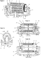
- Figures 4 to 5c depict further components of an, e.g. removable, head of an epilating device with several frames 3 each comprising several pairs of clamping elements arranged on a drum 11.
- the head is provided with the support structure 12 comprising bearings for a shaft defining a rotation axis III about which the drum 11 is rotatable.
- the drum 11 may be rotated by means of an electric motor (not shown) interacting in use with a gear mechanism comprising a pinion 13 meshing with a gear wheel 14 of the drum 11.
- the drum 11 with the several frames 3 and the respective pairs of clamping elements all rotate about rotation axis III with respect to the support structure 12.
- the frames 3 and the levers 4 are arranged parallel to the rotation axis III in the drum 11.
- the frames 3 guiding the respective levers 4 are depicted as individual component parts inserted into drum 11 in the embodiment shown in Figures 4 to 5c .
- the frames 3 may be provided as an integral portion of the drum 11.
- a cam plate 15 is provided on the left side of the drum 11 as seen in Figures 4 and 5b .
- the cam plate 15 is rotationally constrained to the support structure 12 such that the drum 11 rotates relative to the cam plate 15 in use of the device.
- the cam plate 15 is provided with at least one cam 16 protruding towards the drum 11.
- the cam 16 is arranged such that when the drum 11 rotates the levers 4 subsequently abut the cam 16 and are thereby shifted relative to the drum 11 and the cam plate 15 which causes actuation of the second clamps 2 coupled to the respective lever 4 for pivoting of the second clamps 2 into the closed clamping position.
- the pairs of clamping elements of a lever 4 and a frame 3 are automatically closed due to the interaction of the lever 4 with the cam 16 of the cam plate 15 every time the respective lever 4 passes over the cam 16.
- a compression spring 17 is provided in the drum 11 for each of the levers 4.
- the compression springs 17 are arranged such that each spring biases one of the levers 4 towards the cam plate 15, i.e. in a direction for opening the pairs of clamping elements.
- the pairs of clamping elements are automatically moved into their open position by a compression spring 17 when the respective lever 4 loses contact with the cam 16 of the cam plate 15.
- the epilating device further comprises a yoke spring 18 arranged at or the head for biasing the cam plate 15 towards the drum 11 with the levers 4. Due to the yoke spring 18 pressing the cam plate 15 with the cam 16 towards the drum 11 and to the levers 4, the yoke spring 18 provides the clamping force for closing the pairs of clamping elements and for gripping hairs between the first clamp 1 and the second clamp 2. The force exerted by the yoke spring 18 exceeds the force provided by the compression spring 17 such that the levers 4 are axially displaced parallel to the rotation axis III against the bias of the compression spring 17 when the respective lever 4 comes in contact with the cam 16 of the cam plate 15.
- the yoke spring 18 compensates variations in the orientation of the second clamp 2 with respect to the first clamp 1 in the closed clamping position. In other words, with a hair clamped between the first clamp 1 and the second clamp 2, it is possible that the second clamp 2 does not fully reach its parallel orientation with respect to the first clamp 1. This deviation from the parallel orientation depends on the size of the hair gripped between the clamps and depends on the position at which the hair is gripped between the clamps.
- the epilating device according to the present disclosure has a simple structure not requiring a large construction space for providing multiple frames 3 and levers 4 even on the relatively small drum 11. This is based on the orientation of the first pivoting axis I defined by the first pin 8 of the second clamp 2 perpendicular to the rotation axis III and extending in the radial direction of the drum 11. This orientation has the additional benefit of the first clamp 1 and the second clamp 2 forming a V-shaped space in their open position facing in the direction of rotation of the drum 11, thereby guiding the hairs on a user's skin in the V-shaped space.
- levers 4 with the cam 16 can be seen in Figure 4 , in which in the two upper lines the pairs of clamping elements 1, 2 are substantially parallel to each other, i.e. in their closed clamped position, due to the abutment of the upper levers 4 with the cam 16. In contrast to that, in the lower lines of pairs of clamping elements 1, 2, there is no interaction of the respective levers 4 with cam 16, such that the respective springs 17 push the levers back into the open position. Thus, in the lower lines the clamps 1, 2 are inclined to each other, thereby forming a V-shaped opening space for receiving hairs during rotation of drum 11.
Landscapes
- Surgical Instruments (AREA)
Abstract
Description
- The present invention is concerned with an electronically operated hair removing device, in more detail with an epilating device for removing and or plucking hairs from a user's skin.
- Epilating devices often comprise a drum rotating during operation and having several pairs of clamps provided on the drum for plucking hairs from a user's skin.
EP 2 280 623 B1 -
EP 1 289 391 B1EP 1 673 996 A1 - The orientation of the respective pairs of clamps or tweezers resulting in opening and closing substantially in the radial direction of the drum requires a relatively large space of the drum for accommodating the clamps and the actuation mechanism for driving the clamps. In addition, depending on the location and arrangement of the actuation mechanism, opening and closing the clamps in the radial direction of the drum may have drawbacks regarding the transmission of forces for clamping a user's hair. Further, with the clamps opening and closing in the radial direction it is difficult to guide individual hairs between the open clamps.
- It is an object of the present disclosure to provide an improved hair removing device overcoming the above-mentioned drawbacks and restrictions of the known epilating devices.
- In accordance with one aspect of the present disclosure an electrically operable hair removing device, in particular an epilating device for removing hairs from a user's skin, may comprise at least one frame, at least one pair of clamping elements with a first clamp and a second clamp mounted in the frame, wherein each clamp has a skin contact surface facing towards the user's skin during operation of the device. The second clamp may be mounted in the frame pivotable about a first pivoting axis and relative to the first clamp between an open position and a closed clamping position, with the first clamp and the second clamp being inclined with respect to each other in the open position and being at least substantially parallel to each other in the closed position. Especially with one or more hairs clamped or gripped between a pair of clamps when in use, the clamps may have an orientation in the closed clamping position which is not fully parallel to each other, but rather defines an acute angle between the clamps. The device may further comprise at least one displaceable lever mounted in the frame and coupled to the second clamp for pivoting the second clamp relative to the first clamp between the open position and the closed clamping position, and an electrically driven actuation mechanism for driving the displaceable lever with respect to the frame. According to the present disclosure, the first pivoting axis extends perpendicular to the skin contact surfaces of the clamps. If the clamping elements are arranged on a drum rotating during operation of the device, the first pivoting axis preferably extends radially with respect to the axis of rotation of the drum.
- With this orientation of the pivoting axis of the second clamp, the pair of clamps is in a V-shaped orientation with respect to each other as seen from the user's skin when in the open position and the pair of clamps has a reduced opening angle or the clamps are parallel to each other as seen from the user's skin when in the closed clamping position. In other words, the pair of clams opens and closes substantially in a circumferential direction when mounted on a drum.
- The orientation of the clamps with the first pivoting axis extending perpendicular to the skin contact surfaces has the benefit that the clamps substantially extend in parallel to the skin contact surfaces, thereby reducing the axial space required for arranging the clamps. In addition, a clamping force may be transmitted in a more efficient way, thereby improving the hair removing result. Further, the orientation of the clamps facilitates guiding the hairs in the V-shaped space formed between the clamps in their open position.
- Further details and features of the invention may be obtained from the following description of embodiments in conjunction with the drawings.
-
- Figure 1a
- shows in a schematic side view a portion of an embodiment of a device according to the invention in the open position,
- Figure 1b
- shows in a schematic side view a portion of the device of
Figure 1a in the closed clamping position, - Figure 2
- shows in a schematic side view a larger portion of the device of
Figure 1a in the open position, - Figure 3
- shows in a sectional view a portion of the device of
Figure 1a , - Figure 4
- shows in a schematic view a head of an epilating device with several portions according to
Figure 2 , - Figure 5a
- shows a side view of the head of
Figure 4 , - Figure 5b
- shows a sectional view along line A-A in
Figure 5a , and - Figure 5c
- shows a sectional view along line C-C in
Figure 5 a. - In the epilating device the skin contact surfaces of the first clamp and the second clamp are preferably parallel to each other, e.g. in the same plane, both in the open position and in the closed position. In contrast to the known epilating devices opening and closing the pairs of clamps substantially in a radial direction, the skin contact surfaces of the respective clamps remain during operation generally in the plane of the user's skin which may contribute in less skin irritations.
- According to an embodiment of the epilating device, the first clamp may be fixed to the frame. The first clamp may be permanently fixed to the frame such that relative movement between the first clamp and the frame is prevented. For example, the first clamp may be an integral part of the frame. In this embodiment opening and closing the pair of clamps or tweezers is effected by pivoting only the second clamp with respect to the fixed first clamp. This reduces the effort for driving both clams relative to each other. Thus, the design of this embodiment is relatively simple and cost-effective.
- In a further embodiment of the epilating device, the first clamp may be mounted in the frame pivotable about a third pivoting axis and relative to the second clamp between an open position and a closed clamping position, with the first clamp and the second clamp being inclined with respect to each other in the open position and being parallel to each other in the closed position. In this further embodiment both clamps are pivoting between the open position and the closed clamping position.
- The second clamp may be coupled to the displaceable lever pivotable about a second pivoting axis. In other words, a pure linear movement of the displaceable lever, e.g. parallel to the skin contact surfaces, may be translated into a pivoting movement of the second clamp about the first pivoting axis which is preferably parallel and offset to the second pivoting axis.
- In more detail, the second clamp may comprise a first pin and a second pin located at a side of the second clamp opposite the skin contact surface. The first pin is preferably pivotably mounted in the frame and defines the first pivoting axis. Further, the second pin may be pivotably mounted in the displaceable lever and defines the second pivoting axis. With this configuration, the second clamp may be designed as a bar having a flat skin contact surface on one side and the two pins protruding from the side facing away from the skin contact surface. While it is preferred that the first pin defining the first pivoting axis is provided at a first end of the second clamp, the position of the second pin with respect to an opposite second end defining the second pivoting axis coupled to the displaceable lever may vary, thereby adapting the actuation of the second clamp between larger pivoting speed (second pin offset from the second end) and larger clamping force (second pin closer to the second end).
- While it is generally possible to provide an epilating device with only one single pair of clamps, it is preferred that several pairs of clamping elements, i.e. clamps or tweezers, are mounted to one frame to increase hair removing effectivity. The respective first pivoting axes of the several pairs of clamps are preferably parallel to each other and perpendicular to the skin contact surfaces. The design of the drive mechanism fur pivoting the pairs of clamps may be a simple and reliable by coupling the second clamps of the several pairs of clamps to the same displaceable lever.
- According to a further embodiment of the present disclosure, the frame may be provided on a drum or may be a unitary component of a drum, wherein the drum is electrically driven rotatable about a rotation axis extending parallel to the skin contact surfaces. As an alternative to the provision of several frames on a drum, the frames may be provided on a belt. Both alternatives allow providing several frames with several pairs of clamps even with limited construction space in small hair removing devices. In other words, in the epilating device the drum may comprise several frames each comprising several pairs of clamping elements.
- The hair removing result may be increased by providing the pairs of clamping elements of one of the several frames offset in a direction parallel to the rotation axis with respect to the pairs of clamping elements of an adjacent frame. For example, when provided on the drum, the pairs of clamping elements may be offset in increments of less than the width of the pair of clamping elements in the direction of the rotation axis. The size of the increments may be chosen depending on the number of frames on the drum such that after one full revolution of the drum the pairs of clamping elements are offset by about the width of one pair of clamping elements.
- In the epilating device the electrically driven actuation mechanism may comprise an electric motor, at least one cam plate and a gear mechanism for moving the displaceable lever relative to the cam plate. For example, the cam plate may be designed and arranged with respect to the displaceable lever such that the lever is displaced, e.g. in a direction parallel to the rotation axis of the drum, when abutting the cam of the cam plate. This movement of the displaceable lever caused by the interaction with the cam plate may result in pivoting the second clamp from the open position into the closed clamping position. As an alternative to the provision of the cam plate the displaceable lever may be guided with a sliding block in a guide track, thereby causing actuation of the displaceable lever depending on its relative position with respect to the guide track. The provision of a sliding block and the guide track may not only be used for moving the second clamp into the closed clamping position but may also be used for moving the second clamp back into the open position.
- According to an embodiment, the epilating device may further comprise at least one first elastically deformable element, for example a compression spring, wherein the elastically deformable element biases the displaceable lever into the open position of the clamps. Thus, without a driving force acting on the displaceable lever, the lever is shifted into the position in which the pairs of clamping elements are in their open position, i.e. in a V-shaped orientation as seen from the user's skin. The pairs of clamping elements may for example be moved to the closed clamping position only for the relatively short period of time for gripping and clamping the hairs for removal. As an alternative or in addition to the provision of a spring or the like elastically deformable element biasing the clamping elements in their open position, two cam plates may be used for actuating the lever in opposite directions, i.e. for moving the second clamp into the open position and in the closed clamping position, respectively.
- The cam plate of the epilating device may be rotationally fixed to a support comprising bearings for the rotation axis of the drum. The support may be part of or coupled to the housing of the epilating device or may be part of or coupled to an, e.g. removable, head of the epilating device. Further, at least one second elastically deformable element may be provided biasing the cam plate axially parallel to the rotation axis in abutment with the at least one displaceable lever and/or the drum. Thus, the clamping force transmitted by the displaceable lever to the second clamp is provided by the second elastically deformable element, e.g. a spring, acting on the cam plate. If a compression spring or the like is provided as of the first elastically deformable element for biasing the displaceable lever into the open position of the second clamp, the spring force of the second elastically deformable element has to be chosen to be larger than the spring force of the first elastically deformable element. The provision of the second elastically deformable element has the benefit that this spring may compensate different closed clamping positions of the second clamp depending for example from the size and/or the position of the hair gripped by a pair of clamping elements.
- The second elastically deformable element may be a yoke spring, for example arranged such that one end of the yoke spring directly or indirectly acts on the drum while the other end acts directly or indirectly on the cam plate. As an alternative, the second elastically deformable element may be a compression spring arranged between the cam plate and a support structure, thereby biasing the cam plate towards the drum and the levers.
- The orientation of the clamping elements opening substantially in a circumferential direction of the drum or the like has the benefit of guiding hairs into the V-shaped space between the clamping elements. This effect may be further increased by providing at least one of the first clamp and the second clamp comprising a substantially rectangular skin contact surface with a tapering at the end facing away from the first pivoting axis. In other words, the end facing away from the first pivoting axis may have a V-shaped guiding area even in the closed position of the clamping elements. In addition or as an alternative, one or both clamping elements may be flattened in direction of movement of drum.
- In the embodiment depicted in
Figures 1a and 1b , a single pair of clamping elements is depicted in the open state or position (Figure 1a ) and in the closed clamping state or position (Figure 1b ), respectively. The pair of clamping elements comprises afirst clamp 1 and asecond clamp 2. Thefirst clamp 1 is provided as a portion of aframe 3. Thesecond clamp 2 is movable with respect to theframe 3 and thefirst clamp 1. For actuation of the second clamp 2 adisplaceable lever 4 is provided which may be guided in theframe 3 as depicted inFigures 1a and 1b . -
Figures 1a and 1b are enlarged details ofFigure 2 which depicts that theframe 3 may comprise severalfirst clamps 1 and that thedisplaceable lever 4 is coupled to severalsecond clamps 2, thereby forming several pairs of clamping elements which may be opened and closed simultaneously. - Each of the
first clamps 1 and each of thesecond clamps 2 comprises askin contact surface skin contact surfaces first clamps 1 and thesecond clamps 2 have a substantially rectangularskin contact surface first clamps 1 may be provided with a tapering 7 for guiding hairs into the V-shaped space between thefirst clamp 1 and thesecond clamp 2 in the open position (Figure 1a ). -
Figure 3 shows in a sectional view that each of thesecond clamps 2 is provided with twopins skin contact surface 6. Thepins skin contact surface 6 and faces away from theskin contact surface 6. Theframe 3 is provided with an opening for receiving thefirst pin 8 such that thesecond clamp 2 is rotatable (pivotable) about thefirst pin 8 and the first pivoting axis I. Snap elements 10 a may be provided at the free end of thefirst pin 8 such that thefirst pin 8 is axially constrained to theframe 3. Thesecond pin 9 is received in a respective opening of thedisplaceable lever 4 such that thesecond clamp 2 is rotatable (pivotable) about thesecond pin 9 and the second pivoting axis II. With this configuration thesecond clamp 2 is movable in a pivoting manner from its open position as shown inFigures 1a and 2 to its closed clamping position shown inFigure 1b by an axial displacement of thelever 4 with respect to theframe 3 to the right as seen inFigure 2 . Further, thesecond clamp 2 is movable in a pivoting manner from its closed clamping position shown inFigure 1b to its open position as shown inFigures 1a and 2 by an axial displacement of thelever 4 with respect to theframe 3 to the left as seen inFigure 2 . - While
Figures 1a to 2 depict only asingle frame 3 or a portion thereof,Figures 4 to 5c depict further components of an, e.g. removable, head of an epilating device withseveral frames 3 each comprising several pairs of clamping elements arranged on adrum 11. The head is provided with thesupport structure 12 comprising bearings for a shaft defining a rotation axis III about which thedrum 11 is rotatable. Thedrum 11 may be rotated by means of an electric motor (not shown) interacting in use with a gear mechanism comprising apinion 13 meshing with agear wheel 14 of thedrum 11. In other words, in use of the epilating device thedrum 11 with theseveral frames 3 and the respective pairs of clamping elements all rotate about rotation axis III with respect to thesupport structure 12. Theframes 3 and thelevers 4 are arranged parallel to the rotation axis III in thedrum 11. Theframes 3 guiding therespective levers 4 are depicted as individual component parts inserted intodrum 11 in the embodiment shown inFigures 4 to 5c . However, as an alternative, theframes 3 may be provided as an integral portion of thedrum 11. - A
cam plate 15 is provided on the left side of thedrum 11 as seen inFigures 4 and 5b . Thecam plate 15 is rotationally constrained to thesupport structure 12 such that thedrum 11 rotates relative to thecam plate 15 in use of the device. Thecam plate 15 is provided with at least onecam 16 protruding towards thedrum 11. Thecam 16 is arranged such that when thedrum 11 rotates thelevers 4 subsequently abut thecam 16 and are thereby shifted relative to thedrum 11 and thecam plate 15 which causes actuation of thesecond clamps 2 coupled to therespective lever 4 for pivoting of thesecond clamps 2 into the closed clamping position. In other words, during rotation of thedrum 11 relative to thecam plate 15 the pairs of clamping elements of alever 4 and aframe 3 are automatically closed due to the interaction of thelever 4 with thecam 16 of thecam plate 15 every time therespective lever 4 passes over thecam 16. - On the side facing away from the cam plate 15 a
compression spring 17 is provided in thedrum 11 for each of thelevers 4. The compression springs 17 are arranged such that each spring biases one of thelevers 4 towards thecam plate 15, i.e. in a direction for opening the pairs of clamping elements. Thus, the pairs of clamping elements are automatically moved into their open position by acompression spring 17 when therespective lever 4 loses contact with thecam 16 of thecam plate 15. - The epilating device further comprises a
yoke spring 18 arranged at or the head for biasing thecam plate 15 towards thedrum 11 with thelevers 4. Due to theyoke spring 18 pressing thecam plate 15 with thecam 16 towards thedrum 11 and to thelevers 4, theyoke spring 18 provides the clamping force for closing the pairs of clamping elements and for gripping hairs between thefirst clamp 1 and thesecond clamp 2. The force exerted by theyoke spring 18 exceeds the force provided by thecompression spring 17 such that thelevers 4 are axially displaced parallel to the rotation axis III against the bias of thecompression spring 17 when therespective lever 4 comes in contact with thecam 16 of thecam plate 15. - In addition to providing the clamping force, the
yoke spring 18 compensates variations in the orientation of thesecond clamp 2 with respect to thefirst clamp 1 in the closed clamping position. In other words, with a hair clamped between thefirst clamp 1 and thesecond clamp 2, it is possible that thesecond clamp 2 does not fully reach its parallel orientation with respect to thefirst clamp 1. This deviation from the parallel orientation depends on the size of the hair gripped between the clamps and depends on the position at which the hair is gripped between the clamps. - As can be seen in particular from
Figure 4 , the epilating device according to the present disclosure has a simple structure not requiring a large construction space for providingmultiple frames 3 andlevers 4 even on the relativelysmall drum 11. This is based on the orientation of the first pivoting axis I defined by thefirst pin 8 of thesecond clamp 2 perpendicular to the rotation axis III and extending in the radial direction of thedrum 11. This orientation has the additional benefit of thefirst clamp 1 and thesecond clamp 2 forming a V-shaped space in their open position facing in the direction of rotation of thedrum 11, thereby guiding the hairs on a user's skin in the V-shaped space. - The interaction of
levers 4 with thecam 16 can be seen inFigure 4 , in which in the two upper lines the pairs of clampingelements upper levers 4 with thecam 16. In contrast to that, in the lower lines of pairs of clampingelements respective levers 4 withcam 16, such that therespective springs 17 push the levers back into the open position. Thus, in the lower lines theclamps drum 11. - The dimensions and values disclosed herein are not to be understood as being strictly limited to the exact numerical values recited. Instead, unless otherwise specified, each such dimension is intended to mean both the recited value and a functionally equivalent range surrounding that value. For example, a dimension disclosed as "40 mm" is intended to mean "about 40 mm."
-
- 1
- first clamp
- 2
- second clamp
- 3
- frame
- 4
- displaceable lever
- 5
- skin contact surface
- 6
- skin contact surface
- 7
- tapering
- 8
- first pin
- 9
- second pin
- 10
- snap element
- 11
- drum
- 12
- support structure
- 13
- pinion
- 14
- gear wheel
- 15
- cam plate
- 16
- cam
- 17
- compression spring
- 18
- yoke spring
- I
- first pivoting axis
- II
- second pivoting axis
- III
- rotation axis
Claims (15)
- An epilating device for removing hairs from a user's skin, the device comprising:at least one frame (3),at least one pair of clamping elements (1, 2) with a first clamp (1) and a second clamp (2) mounted in the frame (3), wherein each clamp (1, 2) has a skin contact surface (5, 6) facing towards the user's skin,at least one displaceable lever (4) mounted in the frame (3) and coupled to the second clamp (2) for pivoting the second clamp (2) relative to the first clamp (1) between an open position and a closed clamping position, andan electrically driven actuation mechanism (13, 14, 15, 16) for driving the displaceable lever (4) with respect to the frame (3),wherein the second clamp (2) is mounted in the frame (3) pivotable about a first pivoting axis (I) and relative to the first clamp (1) between the open position and the closed clamping position, with the first clamp (1) and the second clamp (2) being inclined with respect to each other in the open position and being parallel to each other in the closed position,characterized in that the first pivoting axis (I) extends perpendicular to the skin contact surfaces (5, 6).
- The epilating device in accordance with claim 1, characterized in that the skin contact surfaces (5, 6) of the first clamp (1) and the second clamp (2) are in the same plane in the open position and in the closed position.
- The epilating device in accordance with any one of the preceding claims, characterized in that the first clamp (1) is fixed to the frame (3).
- The epilating device in accordance with claim 1 or 2, characterized in that the first clamp (1) is mounted in the frame (3) pivotable about a third pivoting axis and relative to the second clamp (2) between an open position and a closed clamping position, with the first clamp (1) and the second clamp (2) being inclined with respect to each other in the open position and being parallel to each other in the closed position.
- The epilating device in accordance with any one of the preceding claims, characterized in that the second clamp (2) is coupled to the displaceable lever (4) pivotable about a second pivoting axis (II).
- The epilating device in accordance with claim 5, characterized in that the second clamp (2) comprises a first pin (8) and a second pin (9) located at a side of the second clamp (2) opposite the skin contact surface (6), wherein the first pin (8) is pivotably mounted in the frame (3) and defines the first pivoting axis (I), and wherein the second pin (9) is pivotably mounted in the displaceable lever (4) and defines the second pivoting axis (II).
- The epilating device in accordance with any one of the preceding claims, characterized in that several pairs of clamping elements (1, 2) are mounted to one frame (3), wherein the first pivoting axes (I) of the several pairs of clamping elements (1, 2) are parallel to each other and perpendicular to the skin contact surfaces (5, 6).
- The epilating device in accordance with claim 7, characterized in that the second clamps (2) of the several pairs of clamping elements (1, 2) are coupled to the displaceable lever (4).
- The epilating device in accordance with any one of the preceding claims, characterized in that, the frame (3) is provided on a drum (11) or is a unitary component of a drum (11), wherein the drum (11) is electrically driven rotatable about a rotation axis (III) extending parallel to the skin contact surfaces (5, 6).
- The epilating device in accordance with claim 9, characterized in that the drum (11) comprises several frames (3) each comprising a lever (4) and several pairs of clamping elements (1, 2).
- The epilating device in accordance with claim 10, characterized in that, the pairs of clamping elements (1, 2) of one of the several frames (3) are offset in a direction parallel to the rotation axis (III) with respect to the pairs of clamping elements (1, 2) of an adjacent frame (3).
- The epilating device in accordance with any one of the preceding claims further comprising at least one first elastically deformable element (17), characterized in that, the elastically deformable element (17) biases the displaceable lever (4) into the open position of the clamps (1, 2).
- The epilating device in accordance with any one of the preceding claims, characterized in that, the electrically driven actuation mechanism comprises an electric motor, at least one cam plate (15) and a gear mechanism (13, 14) for moving the displaceable lever (4) relative to the cam plate (15).
- The epilating device in accordance with claims 9 and 13, characterized in that, the cam plate (15) is rotationally fixed to a support (12) comprising bearings for the rotation axis (III) of the drum (11), wherein at least one second elastically deformable element (18) is provided biasing the cam plate (15) axially parallel to the rotation axis (III) in abutment with the at least one displaceable lever (4) and/or the drum (11).
- The epilating device in accordance with any one of preceding claims, characterized in that at least one of the first clamp 1() and the second clamp (2) comprises a substantially rectangular skin contact surface (5, 6) with the end facing away from the first pivoting axis (I) having a tapering (7).
Priority Applications (5)
| Application Number | Priority Date | Filing Date | Title |
|---|---|---|---|
| ES17176677T ES2764701T3 (en) | 2017-06-19 | 2017-06-19 | Hair removal device |
| EP17176677.7A EP3417737B1 (en) | 2017-06-19 | 2017-06-19 | Epilating device |
| US16/007,416 US10905217B2 (en) | 2017-06-19 | 2018-06-13 | Epilating device |
| PCT/IB2018/054512 WO2018234998A1 (en) | 2017-06-19 | 2018-06-19 | EPILATION DEVICE |
| CN201880040847.9A CN110785101B (en) | 2017-06-19 | 2018-06-19 | hair removal device |
Applications Claiming Priority (1)
| Application Number | Priority Date | Filing Date | Title |
|---|---|---|---|
| EP17176677.7A EP3417737B1 (en) | 2017-06-19 | 2017-06-19 | Epilating device |
Publications (2)
| Publication Number | Publication Date |
|---|---|
| EP3417737A1 true EP3417737A1 (en) | 2018-12-26 |
| EP3417737B1 EP3417737B1 (en) | 2019-10-16 |
Family
ID=59077968
Family Applications (1)
| Application Number | Title | Priority Date | Filing Date |
|---|---|---|---|
| EP17176677.7A Active EP3417737B1 (en) | 2017-06-19 | 2017-06-19 | Epilating device |
Country Status (5)
| Country | Link |
|---|---|
| US (1) | US10905217B2 (en) |
| EP (1) | EP3417737B1 (en) |
| CN (1) | CN110785101B (en) |
| ES (1) | ES2764701T3 (en) |
| WO (1) | WO2018234998A1 (en) |
Cited By (1)
| Publication number | Priority date | Publication date | Assignee | Title |
|---|---|---|---|---|
| US10905217B2 (en) | 2017-06-19 | 2021-02-02 | Braun Gmbh | Epilating device |
Families Citing this family (1)
| Publication number | Priority date | Publication date | Assignee | Title |
|---|---|---|---|---|
| ES2986219T3 (en) | 2020-11-05 | 2024-11-08 | Brilliance Of Beauty Inc | Light-curing artificial nails, preparation methods and methods of use of the same |
Citations (5)
| Publication number | Priority date | Publication date | Assignee | Title |
|---|---|---|---|---|
| EP1289391B1 (en) | 2000-06-15 | 2005-07-27 | Seb S.A. | Depilatory apparatus with plucking members borne by a chain |
| EP1673996A1 (en) | 2004-12-22 | 2006-06-28 | Matsushita Electric Works, Ltd | Epilating apparatus |
| EP2280623B1 (en) | 2008-05-27 | 2012-03-21 | Braun GmbH | Epilation device |
| WO2014053765A1 (en) * | 2012-10-05 | 2014-04-10 | Seb S.A. | Epilation device comprising pivoting tweezers |
| WO2015150695A1 (en) * | 2014-04-04 | 2015-10-08 | Seb S.A. | Magnetic epilator |
Family Cites Families (12)
| Publication number | Priority date | Publication date | Assignee | Title |
|---|---|---|---|---|
| EP0500075B1 (en) * | 1991-02-20 | 1999-05-06 | Matsushita Electric Works, Ltd. | Depilating device |
| IL103071A (en) * | 1991-09-10 | 1995-11-27 | Philips Electronics Nv | Disc-type depilation apparatus |
| DE4309406C2 (en) * | 1993-03-24 | 1995-06-14 | Braun Ag | Epilation device |
| EP1294294A4 (en) * | 2000-06-09 | 2003-09-17 | Moshe Dolev | Hair depilating device utilizing mechanism to spirally align coupled-tweezer elements |
| JP4720887B2 (en) * | 2008-09-22 | 2011-07-13 | パナソニック電工株式会社 | Hair removal equipment |
| JP4720886B2 (en) * | 2008-09-22 | 2011-07-13 | パナソニック電工株式会社 | Hair removal equipment |
| ES2423309T3 (en) * | 2009-03-25 | 2013-09-19 | Braun Gmbh | Hair removal device |
| DE102009035232B4 (en) * | 2009-07-29 | 2014-10-16 | Wahl Gmbh | Cutting set for hair clippers |
| EP2471404B1 (en) * | 2010-12-28 | 2018-06-27 | Braun GmbH | Novel tweezer arrangement for an epilation head |
| EP2471405B1 (en) * | 2010-12-28 | 2016-05-18 | Braun GmbH | Novel tweezer arrangement for an epilation head |
| CN202311826U (en) * | 2011-11-11 | 2012-07-11 | 超人集团有限公司 | Electric unhairing device |
| EP3417737B1 (en) | 2017-06-19 | 2019-10-16 | Braun GmbH | Epilating device |
-
2017
- 2017-06-19 EP EP17176677.7A patent/EP3417737B1/en active Active
- 2017-06-19 ES ES17176677T patent/ES2764701T3/en active Active
-
2018
- 2018-06-13 US US16/007,416 patent/US10905217B2/en active Active
- 2018-06-19 WO PCT/IB2018/054512 patent/WO2018234998A1/en not_active Ceased
- 2018-06-19 CN CN201880040847.9A patent/CN110785101B/en active Active
Patent Citations (5)
| Publication number | Priority date | Publication date | Assignee | Title |
|---|---|---|---|---|
| EP1289391B1 (en) | 2000-06-15 | 2005-07-27 | Seb S.A. | Depilatory apparatus with plucking members borne by a chain |
| EP1673996A1 (en) | 2004-12-22 | 2006-06-28 | Matsushita Electric Works, Ltd | Epilating apparatus |
| EP2280623B1 (en) | 2008-05-27 | 2012-03-21 | Braun GmbH | Epilation device |
| WO2014053765A1 (en) * | 2012-10-05 | 2014-04-10 | Seb S.A. | Epilation device comprising pivoting tweezers |
| WO2015150695A1 (en) * | 2014-04-04 | 2015-10-08 | Seb S.A. | Magnetic epilator |
Cited By (1)
| Publication number | Priority date | Publication date | Assignee | Title |
|---|---|---|---|---|
| US10905217B2 (en) | 2017-06-19 | 2021-02-02 | Braun Gmbh | Epilating device |
Also Published As
| Publication number | Publication date |
|---|---|
| CN110785101B (en) | 2022-09-16 |
| US10905217B2 (en) | 2021-02-02 |
| EP3417737B1 (en) | 2019-10-16 |
| CN110785101A (en) | 2020-02-11 |
| WO2018234998A1 (en) | 2018-12-27 |
| US20180360186A1 (en) | 2018-12-20 |
| ES2764701T3 (en) | 2020-06-04 |
Similar Documents
| Publication | Publication Date | Title |
|---|---|---|
| JP4131360B2 (en) | Electric hand | |
| EP2422611B1 (en) | Handheld power working machine | |
| EP3417737B1 (en) | Epilating device | |
| JP2008142889A (en) | Electric hand tool device | |
| RU2572267C1 (en) | Electrical shaving set with rotating shaving head | |
| US11794361B2 (en) | Group of manual pliers | |
| US20030005586A1 (en) | Pliers and method for cutting amorphous light wave guide cables | |
| CN103796804A (en) | Motor-driven machine tool | |
| JP2022519611A (en) | Connection terminal and connection terminal block | |
| JP5882819B2 (en) | Manual crimping tool | |
| US5620406A (en) | Tool clamping mechanism | |
| US20170125987A1 (en) | Separating and insulation removal device for a cable-processing machine | |
| US7900803B2 (en) | Apparatus for the intermittent supply of a semi-finished material in the form of a band or a wire to a press | |
| US6314843B1 (en) | Parallel pliers | |
| CN120187567A (en) | Hair cutting device and cutting unit for hair cutting device | |
| US20080045975A1 (en) | Epilation Head and Epilation Device | |
| CN109834726B (en) | Electric holding device | |
| US20100076457A1 (en) | Depilatory device | |
| CN104661560B (en) | Epilation device comprising pivoting tweezers | |
| EP3860395B1 (en) | An epilating device for epilating hair | |
| EP3842194A1 (en) | Shaving unit having hair-cutting units with first and second pivot axes | |
| EP4273360B1 (en) | Pivot hinge and pivotal door leaf | |
| JP3192239B2 (en) | Hair removal device | |
| CN110367676B (en) | Epilation head for an epilation device | |
| JP3799535B2 (en) | Disc blade grinding device |
Legal Events
| Date | Code | Title | Description |
|---|---|---|---|
| PUAI | Public reference made under article 153(3) epc to a published international application that has entered the european phase |
Free format text: ORIGINAL CODE: 0009012 |
|
| STAA | Information on the status of an ep patent application or granted ep patent |
Free format text: STATUS: THE APPLICATION HAS BEEN PUBLISHED |
|
| AK | Designated contracting states |
Kind code of ref document: A1 Designated state(s): AL AT BE BG CH CY CZ DE DK EE ES FI FR GB GR HR HU IE IS IT LI LT LU LV MC MK MT NL NO PL PT RO RS SE SI SK SM TR |
|
| AX | Request for extension of the european patent |
Extension state: BA ME |
|
| STAA | Information on the status of an ep patent application or granted ep patent |
Free format text: STATUS: REQUEST FOR EXAMINATION WAS MADE |
|
| 17P | Request for examination filed |
Effective date: 20190313 |
|
| RBV | Designated contracting states (corrected) |
Designated state(s): AL AT BE BG CH CY CZ DE DK EE ES FI FR GB GR HR HU IE IS IT LI LT LU LV MC MK MT NL NO PL PT RO RS SE SI SK SM TR |
|
| GRAP | Despatch of communication of intention to grant a patent |
Free format text: ORIGINAL CODE: EPIDOSNIGR1 |
|
| STAA | Information on the status of an ep patent application or granted ep patent |
Free format text: STATUS: GRANT OF PATENT IS INTENDED |
|
| INTG | Intention to grant announced |
Effective date: 20190516 |
|
| GRAS | Grant fee paid |
Free format text: ORIGINAL CODE: EPIDOSNIGR3 |
|
| GRAA | (expected) grant |
Free format text: ORIGINAL CODE: 0009210 |
|
| STAA | Information on the status of an ep patent application or granted ep patent |
Free format text: STATUS: THE PATENT HAS BEEN GRANTED |
|
| AK | Designated contracting states |
Kind code of ref document: B1 Designated state(s): AL AT BE BG CH CY CZ DE DK EE ES FI FR GB GR HR HU IE IS IT LI LT LU LV MC MK MT NL NO PL PT RO RS SE SI SK SM TR |
|
| REG | Reference to a national code |
Ref country code: GB Ref legal event code: FG4D |
|
| REG | Reference to a national code |
Ref country code: CH Ref legal event code: EP |
|
| REG | Reference to a national code |
Ref country code: DE Ref legal event code: R096 Ref document number: 602017007791 Country of ref document: DE |
|
| REG | Reference to a national code |
Ref country code: IE Ref legal event code: FG4D |
|
| REG | Reference to a national code |
Ref country code: AT Ref legal event code: REF Ref document number: 1190441 Country of ref document: AT Kind code of ref document: T Effective date: 20191115 |
|
| REG | Reference to a national code |
Ref country code: NL Ref legal event code: MP Effective date: 20191016 |
|
| REG | Reference to a national code |
Ref country code: LT Ref legal event code: MG4D |
|
| REG | Reference to a national code |
Ref country code: AT Ref legal event code: MK05 Ref document number: 1190441 Country of ref document: AT Kind code of ref document: T Effective date: 20191016 |
|
| PG25 | Lapsed in a contracting state [announced via postgrant information from national office to epo] |
Ref country code: SE Free format text: LAPSE BECAUSE OF FAILURE TO SUBMIT A TRANSLATION OF THE DESCRIPTION OR TO PAY THE FEE WITHIN THE PRESCRIBED TIME-LIMIT Effective date: 20191016 Ref country code: AT Free format text: LAPSE BECAUSE OF FAILURE TO SUBMIT A TRANSLATION OF THE DESCRIPTION OR TO PAY THE FEE WITHIN THE PRESCRIBED TIME-LIMIT Effective date: 20191016 Ref country code: LV Free format text: LAPSE BECAUSE OF FAILURE TO SUBMIT A TRANSLATION OF THE DESCRIPTION OR TO PAY THE FEE WITHIN THE PRESCRIBED TIME-LIMIT Effective date: 20191016 Ref country code: PL Free format text: LAPSE BECAUSE OF FAILURE TO SUBMIT A TRANSLATION OF THE DESCRIPTION OR TO PAY THE FEE WITHIN THE PRESCRIBED TIME-LIMIT Effective date: 20191016 Ref country code: GR Free format text: LAPSE BECAUSE OF FAILURE TO SUBMIT A TRANSLATION OF THE DESCRIPTION OR TO PAY THE FEE WITHIN THE PRESCRIBED TIME-LIMIT Effective date: 20200117 Ref country code: LT Free format text: LAPSE BECAUSE OF FAILURE TO SUBMIT A TRANSLATION OF THE DESCRIPTION OR TO PAY THE FEE WITHIN THE PRESCRIBED TIME-LIMIT Effective date: 20191016 Ref country code: NL Free format text: LAPSE BECAUSE OF FAILURE TO SUBMIT A TRANSLATION OF THE DESCRIPTION OR TO PAY THE FEE WITHIN THE PRESCRIBED TIME-LIMIT Effective date: 20191016 Ref country code: PT Free format text: LAPSE BECAUSE OF FAILURE TO SUBMIT A TRANSLATION OF THE DESCRIPTION OR TO PAY THE FEE WITHIN THE PRESCRIBED TIME-LIMIT Effective date: 20200217 Ref country code: NO Free format text: LAPSE BECAUSE OF FAILURE TO SUBMIT A TRANSLATION OF THE DESCRIPTION OR TO PAY THE FEE WITHIN THE PRESCRIBED TIME-LIMIT Effective date: 20200116 Ref country code: FI Free format text: LAPSE BECAUSE OF FAILURE TO SUBMIT A TRANSLATION OF THE DESCRIPTION OR TO PAY THE FEE WITHIN THE PRESCRIBED TIME-LIMIT Effective date: 20191016 Ref country code: BG Free format text: LAPSE BECAUSE OF FAILURE TO SUBMIT A TRANSLATION OF THE DESCRIPTION OR TO PAY THE FEE WITHIN THE PRESCRIBED TIME-LIMIT Effective date: 20200116 |
|
| PG25 | Lapsed in a contracting state [announced via postgrant information from national office to epo] |
Ref country code: HR Free format text: LAPSE BECAUSE OF FAILURE TO SUBMIT A TRANSLATION OF THE DESCRIPTION OR TO PAY THE FEE WITHIN THE PRESCRIBED TIME-LIMIT Effective date: 20191016 Ref country code: IS Free format text: LAPSE BECAUSE OF FAILURE TO SUBMIT A TRANSLATION OF THE DESCRIPTION OR TO PAY THE FEE WITHIN THE PRESCRIBED TIME-LIMIT Effective date: 20200224 Ref country code: RS Free format text: LAPSE BECAUSE OF FAILURE TO SUBMIT A TRANSLATION OF THE DESCRIPTION OR TO PAY THE FEE WITHIN THE PRESCRIBED TIME-LIMIT Effective date: 20191016 |
|
| REG | Reference to a national code |
Ref country code: ES Ref legal event code: FG2A Ref document number: 2764701 Country of ref document: ES Kind code of ref document: T3 Effective date: 20200604 |
|
| PG25 | Lapsed in a contracting state [announced via postgrant information from national office to epo] |
Ref country code: AL Free format text: LAPSE BECAUSE OF FAILURE TO SUBMIT A TRANSLATION OF THE DESCRIPTION OR TO PAY THE FEE WITHIN THE PRESCRIBED TIME-LIMIT Effective date: 20191016 |
|
| REG | Reference to a national code |
Ref country code: DE Ref legal event code: R097 Ref document number: 602017007791 Country of ref document: DE |
|
| PG2D | Information on lapse in contracting state deleted |
Ref country code: IS |
|
| PG25 | Lapsed in a contracting state [announced via postgrant information from national office to epo] |
Ref country code: CZ Free format text: LAPSE BECAUSE OF FAILURE TO SUBMIT A TRANSLATION OF THE DESCRIPTION OR TO PAY THE FEE WITHIN THE PRESCRIBED TIME-LIMIT Effective date: 20191016 Ref country code: RO Free format text: LAPSE BECAUSE OF FAILURE TO SUBMIT A TRANSLATION OF THE DESCRIPTION OR TO PAY THE FEE WITHIN THE PRESCRIBED TIME-LIMIT Effective date: 20191016 Ref country code: DK Free format text: LAPSE BECAUSE OF FAILURE TO SUBMIT A TRANSLATION OF THE DESCRIPTION OR TO PAY THE FEE WITHIN THE PRESCRIBED TIME-LIMIT Effective date: 20191016 Ref country code: EE Free format text: LAPSE BECAUSE OF FAILURE TO SUBMIT A TRANSLATION OF THE DESCRIPTION OR TO PAY THE FEE WITHIN THE PRESCRIBED TIME-LIMIT Effective date: 20191016 Ref country code: IS Free format text: LAPSE BECAUSE OF FAILURE TO SUBMIT A TRANSLATION OF THE DESCRIPTION OR TO PAY THE FEE WITHIN THE PRESCRIBED TIME-LIMIT Effective date: 20200216 |
|
| PLBE | No opposition filed within time limit |
Free format text: ORIGINAL CODE: 0009261 |
|
| STAA | Information on the status of an ep patent application or granted ep patent |
Free format text: STATUS: NO OPPOSITION FILED WITHIN TIME LIMIT |
|
| PG25 | Lapsed in a contracting state [announced via postgrant information from national office to epo] |
Ref country code: SK Free format text: LAPSE BECAUSE OF FAILURE TO SUBMIT A TRANSLATION OF THE DESCRIPTION OR TO PAY THE FEE WITHIN THE PRESCRIBED TIME-LIMIT Effective date: 20191016 Ref country code: IT Free format text: LAPSE BECAUSE OF FAILURE TO SUBMIT A TRANSLATION OF THE DESCRIPTION OR TO PAY THE FEE WITHIN THE PRESCRIBED TIME-LIMIT Effective date: 20191016 Ref country code: SM Free format text: LAPSE BECAUSE OF FAILURE TO SUBMIT A TRANSLATION OF THE DESCRIPTION OR TO PAY THE FEE WITHIN THE PRESCRIBED TIME-LIMIT Effective date: 20191016 |
|
| 26N | No opposition filed |
Effective date: 20200717 |
|
| PG25 | Lapsed in a contracting state [announced via postgrant information from national office to epo] |
Ref country code: SI Free format text: LAPSE BECAUSE OF FAILURE TO SUBMIT A TRANSLATION OF THE DESCRIPTION OR TO PAY THE FEE WITHIN THE PRESCRIBED TIME-LIMIT Effective date: 20191016 |
|
| PG25 | Lapsed in a contracting state [announced via postgrant information from national office to epo] |
Ref country code: MC Free format text: LAPSE BECAUSE OF FAILURE TO SUBMIT A TRANSLATION OF THE DESCRIPTION OR TO PAY THE FEE WITHIN THE PRESCRIBED TIME-LIMIT Effective date: 20191016 |
|
| REG | Reference to a national code |
Ref country code: CH Ref legal event code: PL |
|
| PG25 | Lapsed in a contracting state [announced via postgrant information from national office to epo] |
Ref country code: LU Free format text: LAPSE BECAUSE OF NON-PAYMENT OF DUE FEES Effective date: 20200619 |
|
| REG | Reference to a national code |
Ref country code: BE Ref legal event code: MM Effective date: 20200630 |
|
| PG25 | Lapsed in a contracting state [announced via postgrant information from national office to epo] |
Ref country code: CH Free format text: LAPSE BECAUSE OF NON-PAYMENT OF DUE FEES Effective date: 20200630 Ref country code: LI Free format text: LAPSE BECAUSE OF NON-PAYMENT OF DUE FEES Effective date: 20200630 Ref country code: IE Free format text: LAPSE BECAUSE OF NON-PAYMENT OF DUE FEES Effective date: 20200619 |
|
| PG25 | Lapsed in a contracting state [announced via postgrant information from national office to epo] |
Ref country code: BE Free format text: LAPSE BECAUSE OF NON-PAYMENT OF DUE FEES Effective date: 20200630 |
|
| GBPC | Gb: european patent ceased through non-payment of renewal fee |
Effective date: 20210619 |
|
| PG25 | Lapsed in a contracting state [announced via postgrant information from national office to epo] |
Ref country code: GB Free format text: LAPSE BECAUSE OF NON-PAYMENT OF DUE FEES Effective date: 20210619 |
|
| PG25 | Lapsed in a contracting state [announced via postgrant information from national office to epo] |
Ref country code: TR Free format text: LAPSE BECAUSE OF FAILURE TO SUBMIT A TRANSLATION OF THE DESCRIPTION OR TO PAY THE FEE WITHIN THE PRESCRIBED TIME-LIMIT Effective date: 20191016 Ref country code: MT Free format text: LAPSE BECAUSE OF FAILURE TO SUBMIT A TRANSLATION OF THE DESCRIPTION OR TO PAY THE FEE WITHIN THE PRESCRIBED TIME-LIMIT Effective date: 20191016 Ref country code: CY Free format text: LAPSE BECAUSE OF FAILURE TO SUBMIT A TRANSLATION OF THE DESCRIPTION OR TO PAY THE FEE WITHIN THE PRESCRIBED TIME-LIMIT Effective date: 20191016 |
|
| PG25 | Lapsed in a contracting state [announced via postgrant information from national office to epo] |
Ref country code: MK Free format text: LAPSE BECAUSE OF FAILURE TO SUBMIT A TRANSLATION OF THE DESCRIPTION OR TO PAY THE FEE WITHIN THE PRESCRIBED TIME-LIMIT Effective date: 20191016 |
|
| P01 | Opt-out of the competence of the unified patent court (upc) registered |
Effective date: 20230430 |
|
| PGFP | Annual fee paid to national office [announced via postgrant information from national office to epo] |
Ref country code: DE Payment date: 20250429 Year of fee payment: 9 |
|
| PGFP | Annual fee paid to national office [announced via postgrant information from national office to epo] |
Ref country code: FR Payment date: 20250508 Year of fee payment: 9 |
|
| PGFP | Annual fee paid to national office [announced via postgrant information from national office to epo] |
Ref country code: ES Payment date: 20250707 Year of fee payment: 9 |