EP3417730B1 - Protection device and method for performing an impact test on such a protection device - Google Patents
Protection device and method for performing an impact test on such a protection device Download PDFInfo
- Publication number
- EP3417730B1 EP3417730B1 EP18179292.0A EP18179292A EP3417730B1 EP 3417730 B1 EP3417730 B1 EP 3417730B1 EP 18179292 A EP18179292 A EP 18179292A EP 3417730 B1 EP3417730 B1 EP 3417730B1
- Authority
- EP
- European Patent Office
- Prior art keywords
- inflatable element
- protective
- operating region
- boundary
- zone
- Prior art date
- Legal status (The legal status is an assumption and is not a legal conclusion. Google has not performed a legal analysis and makes no representation as to the accuracy of the status listed.)
- Active
Links
Images


Classifications
-
- A—HUMAN NECESSITIES
- A41—WEARING APPAREL
- A41D—OUTERWEAR; PROTECTIVE GARMENTS; ACCESSORIES
- A41D13/00—Professional, industrial or sporting protective garments, e.g. surgeons' gowns or garments protecting against blows or punches
- A41D13/015—Professional, industrial or sporting protective garments, e.g. surgeons' gowns or garments protecting against blows or punches with shock-absorbing means
- A41D13/018—Professional, industrial or sporting protective garments, e.g. surgeons' gowns or garments protecting against blows or punches with shock-absorbing means inflatable automatically
-
- A—HUMAN NECESSITIES
- A41—WEARING APPAREL
- A41D—OUTERWEAR; PROTECTIVE GARMENTS; ACCESSORIES
- A41D13/00—Professional, industrial or sporting protective garments, e.g. surgeons' gowns or garments protecting against blows or punches
- A41D13/05—Professional, industrial or sporting protective garments, e.g. surgeons' gowns or garments protecting against blows or punches protecting only a particular body part
- A41D13/0512—Neck or shoulders area
-
- A—HUMAN NECESSITIES
- A41—WEARING APPAREL
- A41D—OUTERWEAR; PROTECTIVE GARMENTS; ACCESSORIES
- A41D13/00—Professional, industrial or sporting protective garments, e.g. surgeons' gowns or garments protecting against blows or punches
- A41D13/05—Professional, industrial or sporting protective garments, e.g. surgeons' gowns or garments protecting against blows or punches protecting only a particular body part
- A41D13/0518—Chest
-
- A—HUMAN NECESSITIES
- A41—WEARING APPAREL
- A41D—OUTERWEAR; PROTECTIVE GARMENTS; ACCESSORIES
- A41D13/00—Professional, industrial or sporting protective garments, e.g. surgeons' gowns or garments protecting against blows or punches
- A41D13/05—Professional, industrial or sporting protective garments, e.g. surgeons' gowns or garments protecting against blows or punches protecting only a particular body part
- A41D13/0531—Spine
-
- A—HUMAN NECESSITIES
- A63—SPORTS; GAMES; AMUSEMENTS
- A63B—APPARATUS FOR PHYSICAL TRAINING, GYMNASTICS, SWIMMING, CLIMBING, OR FENCING; BALL GAMES; TRAINING EQUIPMENT
- A63B71/00—Games or sports accessories not covered in groups A63B1/00 - A63B69/00
- A63B71/08—Body-protectors for players or sportsmen, i.e. body-protecting accessories affording protection of body parts against blows or collisions
- A63B71/081—Body-protectors for players or sportsmen, i.e. body-protecting accessories affording protection of body parts against blows or collisions fluid-filled, e.g. air-filled
-
- A—HUMAN NECESSITIES
- A63—SPORTS; GAMES; AMUSEMENTS
- A63B—APPARATUS FOR PHYSICAL TRAINING, GYMNASTICS, SWIMMING, CLIMBING, OR FENCING; BALL GAMES; TRAINING EQUIPMENT
- A63B71/00—Games or sports accessories not covered in groups A63B1/00 - A63B69/00
- A63B71/08—Body-protectors for players or sportsmen, i.e. body-protecting accessories affording protection of body parts against blows or collisions
- A63B71/12—Body-protectors for players or sportsmen, i.e. body-protecting accessories affording protection of body parts against blows or collisions for the body or the legs, e.g. for the shoulders
-
- B—PERFORMING OPERATIONS; TRANSPORTING
- B32—LAYERED PRODUCTS
- B32B—LAYERED PRODUCTS, i.e. PRODUCTS BUILT-UP OF STRATA OF FLAT OR NON-FLAT, e.g. CELLULAR OR HONEYCOMB, FORM
- B32B1/00—Layered products having a non-planar shape
- B32B1/08—Tubular products
-
- B—PERFORMING OPERATIONS; TRANSPORTING
- B32—LAYERED PRODUCTS
- B32B—LAYERED PRODUCTS, i.e. PRODUCTS BUILT-UP OF STRATA OF FLAT OR NON-FLAT, e.g. CELLULAR OR HONEYCOMB, FORM
- B32B3/00—Layered products comprising a layer with external or internal discontinuities or unevennesses, or a layer of non-planar shape; Layered products comprising a layer having particular features of form
- B32B3/02—Layered products comprising a layer with external or internal discontinuities or unevennesses, or a layer of non-planar shape; Layered products comprising a layer having particular features of form characterised by features of form at particular places, e.g. in edge regions
- B32B3/08—Layered products comprising a layer with external or internal discontinuities or unevennesses, or a layer of non-planar shape; Layered products comprising a layer having particular features of form characterised by features of form at particular places, e.g. in edge regions characterised by added members at particular parts
-
- B—PERFORMING OPERATIONS; TRANSPORTING
- B32—LAYERED PRODUCTS
- B32B—LAYERED PRODUCTS, i.e. PRODUCTS BUILT-UP OF STRATA OF FLAT OR NON-FLAT, e.g. CELLULAR OR HONEYCOMB, FORM
- B32B5/00—Layered products characterised by the non- homogeneity or physical structure, i.e. comprising a fibrous, filamentary, particulate or foam layer; Layered products characterised by having a layer differing constitutionally or physically in different parts
- B32B5/02—Layered products characterised by the non- homogeneity or physical structure, i.e. comprising a fibrous, filamentary, particulate or foam layer; Layered products characterised by having a layer differing constitutionally or physically in different parts characterised by structural features of a fibrous or filamentary layer
- B32B5/026—Knitted fabric
-
- B—PERFORMING OPERATIONS; TRANSPORTING
- B32—LAYERED PRODUCTS
- B32B—LAYERED PRODUCTS, i.e. PRODUCTS BUILT-UP OF STRATA OF FLAT OR NON-FLAT, e.g. CELLULAR OR HONEYCOMB, FORM
- B32B5/00—Layered products characterised by the non- homogeneity or physical structure, i.e. comprising a fibrous, filamentary, particulate or foam layer; Layered products characterised by having a layer differing constitutionally or physically in different parts
- B32B5/02—Layered products characterised by the non- homogeneity or physical structure, i.e. comprising a fibrous, filamentary, particulate or foam layer; Layered products characterised by having a layer differing constitutionally or physically in different parts characterised by structural features of a fibrous or filamentary layer
- B32B5/028—Net structure, e.g. spaced apart filaments bonded at the crossing points
-
- B—PERFORMING OPERATIONS; TRANSPORTING
- B32—LAYERED PRODUCTS
- B32B—LAYERED PRODUCTS, i.e. PRODUCTS BUILT-UP OF STRATA OF FLAT OR NON-FLAT, e.g. CELLULAR OR HONEYCOMB, FORM
- B32B5/00—Layered products characterised by the non- homogeneity or physical structure, i.e. comprising a fibrous, filamentary, particulate or foam layer; Layered products characterised by having a layer differing constitutionally or physically in different parts
- B32B5/02—Layered products characterised by the non- homogeneity or physical structure, i.e. comprising a fibrous, filamentary, particulate or foam layer; Layered products characterised by having a layer differing constitutionally or physically in different parts characterised by structural features of a fibrous or filamentary layer
- B32B5/08—Layered products characterised by the non- homogeneity or physical structure, i.e. comprising a fibrous, filamentary, particulate or foam layer; Layered products characterised by having a layer differing constitutionally or physically in different parts characterised by structural features of a fibrous or filamentary layer the fibres or filaments of a layer being of different substances, e.g. conjugate fibres, mixture of different fibres
-
- B—PERFORMING OPERATIONS; TRANSPORTING
- B32—LAYERED PRODUCTS
- B32B—LAYERED PRODUCTS, i.e. PRODUCTS BUILT-UP OF STRATA OF FLAT OR NON-FLAT, e.g. CELLULAR OR HONEYCOMB, FORM
- B32B5/00—Layered products characterised by the non- homogeneity or physical structure, i.e. comprising a fibrous, filamentary, particulate or foam layer; Layered products characterised by having a layer differing constitutionally or physically in different parts
- B32B5/14—Layered products characterised by the non- homogeneity or physical structure, i.e. comprising a fibrous, filamentary, particulate or foam layer; Layered products characterised by having a layer differing constitutionally or physically in different parts characterised by a layer differing constitutionally or physically in different parts, e.g. denser near its faces
- B32B5/145—Variation across the thickness of the layer
-
- B—PERFORMING OPERATIONS; TRANSPORTING
- B32—LAYERED PRODUCTS
- B32B—LAYERED PRODUCTS, i.e. PRODUCTS BUILT-UP OF STRATA OF FLAT OR NON-FLAT, e.g. CELLULAR OR HONEYCOMB, FORM
- B32B5/00—Layered products characterised by the non- homogeneity or physical structure, i.e. comprising a fibrous, filamentary, particulate or foam layer; Layered products characterised by having a layer differing constitutionally or physically in different parts
- B32B5/22—Layered products characterised by the non- homogeneity or physical structure, i.e. comprising a fibrous, filamentary, particulate or foam layer; Layered products characterised by having a layer differing constitutionally or physically in different parts characterised by the presence of two or more layers which are next to each other and are fibrous, filamentary, formed of particles or foamed
-
- B—PERFORMING OPERATIONS; TRANSPORTING
- B32—LAYERED PRODUCTS
- B32B—LAYERED PRODUCTS, i.e. PRODUCTS BUILT-UP OF STRATA OF FLAT OR NON-FLAT, e.g. CELLULAR OR HONEYCOMB, FORM
- B32B5/00—Layered products characterised by the non- homogeneity or physical structure, i.e. comprising a fibrous, filamentary, particulate or foam layer; Layered products characterised by having a layer differing constitutionally or physically in different parts
- B32B5/22—Layered products characterised by the non- homogeneity or physical structure, i.e. comprising a fibrous, filamentary, particulate or foam layer; Layered products characterised by having a layer differing constitutionally or physically in different parts characterised by the presence of two or more layers which are next to each other and are fibrous, filamentary, formed of particles or foamed
- B32B5/24—Layered products characterised by the non- homogeneity or physical structure, i.e. comprising a fibrous, filamentary, particulate or foam layer; Layered products characterised by having a layer differing constitutionally or physically in different parts characterised by the presence of two or more layers which are next to each other and are fibrous, filamentary, formed of particles or foamed one layer being a fibrous or filamentary layer
- B32B5/26—Layered products characterised by the non- homogeneity or physical structure, i.e. comprising a fibrous, filamentary, particulate or foam layer; Layered products characterised by having a layer differing constitutionally or physically in different parts characterised by the presence of two or more layers which are next to each other and are fibrous, filamentary, formed of particles or foamed one layer being a fibrous or filamentary layer another layer next to it also being fibrous or filamentary
-
- B—PERFORMING OPERATIONS; TRANSPORTING
- B32—LAYERED PRODUCTS
- B32B—LAYERED PRODUCTS, i.e. PRODUCTS BUILT-UP OF STRATA OF FLAT OR NON-FLAT, e.g. CELLULAR OR HONEYCOMB, FORM
- B32B7/00—Layered products characterised by the relation between layers; Layered products characterised by the relative orientation of features between layers, or by the relative values of a measurable parameter between layers, i.e. products comprising layers having different physical, chemical or physicochemical properties; Layered products characterised by the interconnection of layers
- B32B7/04—Interconnection of layers
- B32B7/12—Interconnection of layers using interposed adhesives or interposed materials with bonding properties
-
- D—TEXTILES; PAPER
- D04—BRAIDING; LACE-MAKING; KNITTING; TRIMMINGS; NON-WOVEN FABRICS
- D04B—KNITTING
- D04B1/00—Weft knitting processes for the production of fabrics or articles not dependent on the use of particular machines; Fabrics or articles defined by such processes
- D04B1/22—Weft knitting processes for the production of fabrics or articles not dependent on the use of particular machines; Fabrics or articles defined by such processes specially adapted for knitting goods of particular configuration
- D04B1/24—Weft knitting processes for the production of fabrics or articles not dependent on the use of particular machines; Fabrics or articles defined by such processes specially adapted for knitting goods of particular configuration wearing apparel
-
- A—HUMAN NECESSITIES
- A41—WEARING APPAREL
- A41D—OUTERWEAR; PROTECTIVE GARMENTS; ACCESSORIES
- A41D2500/00—Materials for garments
- A41D2500/10—Knitted
-
- A—HUMAN NECESSITIES
- A41—WEARING APPAREL
- A41D—OUTERWEAR; PROTECTIVE GARMENTS; ACCESSORIES
- A41D2600/00—Uses of garments specially adapted for specific purposes
- A41D2600/10—Uses of garments specially adapted for specific purposes for sport activities
- A41D2600/102—Motorcycling
-
- A—HUMAN NECESSITIES
- A41—WEARING APPAREL
- A41D—OUTERWEAR; PROTECTIVE GARMENTS; ACCESSORIES
- A41D31/00—Materials specially adapted for outerwear
- A41D31/04—Materials specially adapted for outerwear characterised by special function or use
- A41D31/28—Shock absorbing
- A41D31/285—Shock absorbing using layered materials
-
- B—PERFORMING OPERATIONS; TRANSPORTING
- B32—LAYERED PRODUCTS
- B32B—LAYERED PRODUCTS, i.e. PRODUCTS BUILT-UP OF STRATA OF FLAT OR NON-FLAT, e.g. CELLULAR OR HONEYCOMB, FORM
- B32B2250/00—Layers arrangement
- B32B2250/03—3 layers
-
- B—PERFORMING OPERATIONS; TRANSPORTING
- B32—LAYERED PRODUCTS
- B32B—LAYERED PRODUCTS, i.e. PRODUCTS BUILT-UP OF STRATA OF FLAT OR NON-FLAT, e.g. CELLULAR OR HONEYCOMB, FORM
- B32B2250/00—Layers arrangement
- B32B2250/20—All layers being fibrous or filamentary
-
- B—PERFORMING OPERATIONS; TRANSPORTING
- B32—LAYERED PRODUCTS
- B32B—LAYERED PRODUCTS, i.e. PRODUCTS BUILT-UP OF STRATA OF FLAT OR NON-FLAT, e.g. CELLULAR OR HONEYCOMB, FORM
- B32B2255/00—Coating on the layer surface
- B32B2255/02—Coating on the layer surface on fibrous or filamentary layer
-
- B—PERFORMING OPERATIONS; TRANSPORTING
- B32—LAYERED PRODUCTS
- B32B—LAYERED PRODUCTS, i.e. PRODUCTS BUILT-UP OF STRATA OF FLAT OR NON-FLAT, e.g. CELLULAR OR HONEYCOMB, FORM
- B32B2307/00—Properties of the layers or laminate
- B32B2307/50—Properties of the layers or laminate having particular mechanical properties
- B32B2307/51—Elastic
-
- B—PERFORMING OPERATIONS; TRANSPORTING
- B32—LAYERED PRODUCTS
- B32B—LAYERED PRODUCTS, i.e. PRODUCTS BUILT-UP OF STRATA OF FLAT OR NON-FLAT, e.g. CELLULAR OR HONEYCOMB, FORM
- B32B2307/00—Properties of the layers or laminate
- B32B2307/50—Properties of the layers or laminate having particular mechanical properties
- B32B2307/558—Impact strength, toughness
-
- B—PERFORMING OPERATIONS; TRANSPORTING
- B32—LAYERED PRODUCTS
- B32B—LAYERED PRODUCTS, i.e. PRODUCTS BUILT-UP OF STRATA OF FLAT OR NON-FLAT, e.g. CELLULAR OR HONEYCOMB, FORM
- B32B2307/00—Properties of the layers or laminate
- B32B2307/70—Other properties
- B32B2307/726—Permeability to liquids, absorption
- B32B2307/7265—Non-permeable
-
- B—PERFORMING OPERATIONS; TRANSPORTING
- B32—LAYERED PRODUCTS
- B32B—LAYERED PRODUCTS, i.e. PRODUCTS BUILT-UP OF STRATA OF FLAT OR NON-FLAT, e.g. CELLULAR OR HONEYCOMB, FORM
- B32B2437/00—Clothing
-
- B—PERFORMING OPERATIONS; TRANSPORTING
- B32—LAYERED PRODUCTS
- B32B—LAYERED PRODUCTS, i.e. PRODUCTS BUILT-UP OF STRATA OF FLAT OR NON-FLAT, e.g. CELLULAR OR HONEYCOMB, FORM
- B32B2571/00—Protective equipment
-
- B—PERFORMING OPERATIONS; TRANSPORTING
- B62—LAND VEHICLES FOR TRAVELLING OTHERWISE THAN ON RAILS
- B62J—CYCLE SADDLES OR SEATS; AUXILIARY DEVICES OR ACCESSORIES SPECIALLY ADAPTED TO CYCLES AND NOT OTHERWISE PROVIDED FOR, e.g. ARTICLE CARRIERS OR CYCLE PROTECTORS
- B62J27/00—Safety equipment
- B62J27/20—Airbags specially adapted for motorcycles or the like
-
- D—TEXTILES; PAPER
- D10—INDEXING SCHEME ASSOCIATED WITH SUBLASSES OF SECTION D, RELATING TO TEXTILES
- D10B—INDEXING SCHEME ASSOCIATED WITH SUBLASSES OF SECTION D, RELATING TO TEXTILES
- D10B2401/00—Physical properties
- D10B2401/06—Load-responsive characteristics
- D10B2401/062—Load-responsive characteristics stiff, shape retention
-
- D—TEXTILES; PAPER
- D10—INDEXING SCHEME ASSOCIATED WITH SUBLASSES OF SECTION D, RELATING TO TEXTILES
- D10B—INDEXING SCHEME ASSOCIATED WITH SUBLASSES OF SECTION D, RELATING TO TEXTILES
- D10B2403/00—Details of fabric structure established in the fabric forming process
- D10B2403/01—Surface features
- D10B2403/012—Alike front and back faces
- D10B2403/0122—Smooth surfaces, e.g. laminated or coated
-
- D—TEXTILES; PAPER
- D10—INDEXING SCHEME ASSOCIATED WITH SUBLASSES OF SECTION D, RELATING TO TEXTILES
- D10B—INDEXING SCHEME ASSOCIATED WITH SUBLASSES OF SECTION D, RELATING TO TEXTILES
- D10B2403/00—Details of fabric structure established in the fabric forming process
- D10B2403/02—Cross-sectional features
- D10B2403/022—Lofty fabric with variably spaced front and back plies, e.g. spacer fabrics
- D10B2403/0222—Lofty fabric with variably spaced front and back plies, e.g. spacer fabrics with at least one baggy or puckered ply
-
- D—TEXTILES; PAPER
- D10—INDEXING SCHEME ASSOCIATED WITH SUBLASSES OF SECTION D, RELATING TO TEXTILES
- D10B—INDEXING SCHEME ASSOCIATED WITH SUBLASSES OF SECTION D, RELATING TO TEXTILES
- D10B2403/00—Details of fabric structure established in the fabric forming process
- D10B2403/03—Shape features
- D10B2403/032—Flat fabric of variable width, e.g. including one or more fashioned panels
-
- D—TEXTILES; PAPER
- D10—INDEXING SCHEME ASSOCIATED WITH SUBLASSES OF SECTION D, RELATING TO TEXTILES
- D10B—INDEXING SCHEME ASSOCIATED WITH SUBLASSES OF SECTION D, RELATING TO TEXTILES
- D10B2501/00—Wearing apparel
- D10B2501/04—Outerwear; Protective garments
Definitions
- the present invention relates to a protective device for a protection of a user, preferably a wearable protective device.
- the present invention also relates to a garment including the protective device.
- the protective device includes an inflatable element suitable for protecting the user's body, such as a passenger, a motor-vehicle driver, a skier, a horseman, or a similar user, against impacts and/or falls, or to prevent the consequences of an impact or fall, during a sporting and/or work activity.
- a protective device is, for example, described in the international patent application WO2010067288 disclosing the preamble of claim 1.
- the inflatable element is a bivalve casing formed by two opposite walls or sheets, a structure including a first mesh and a second mesh and tie elements fasten to the meshes.
- the tie elements preferably connect opposing portions of the inflatable element.
- Each mesh is adheringly associated with the respective wall.
- the tie elements are threads and have opposite ends firmly fasten to the mesh of the respective wall.
- the fastening at the opposite ends of the tie elements is, for example, obtained by interweaving tie elements between the threads of the mesh.
- the length of the tie elements is adjusted so that the tie elements have a condition of maximum tension and/or maximum extension when the inflatable element is inflated.
- the shape and size of the inflatable element can be controlled and established a priori, since the maximum expansion of the inflatable element can be controlled by checking the length and the maximum tension of the tie elements.
- the present invention stems from an observation by the inventors of the present invention regarding the way an impact test or certification test is carried out, for example the one according to the European standard EN 1621.4. This observation should also be considered as part of the invention.
- the impact test is carried out by means of a device that includes a striking body or hammer which is dropped onto an anvil onto which a portion of the inflatable element in an inflated condition has previously been placed.
- a device that includes a striking body or hammer which is dropped onto an anvil onto which a portion of the inflatable element in an inflated condition has previously been placed.
- a central region of the portion of the inflatable element is positioned onto an anvil and exposed to the striking body.
- the anvil has a load cell inside of it.
- the portion of the inflatable element is moved along a trajectory, thus allowing the striking body to impact on the whole portion of the inflatable element intended for protection.
- the residual energy after the impact is measured by the load cell and this value, appropriately averaged and filtered, represents the force that the user's body would receive.
- the portion of the inflatable element undergoing the test is intended as an operative protective region, i.e. the region of the inflatable element lain on the anvil and exposed to impact by the striking body, and, that must comply with the test.
- the impact zone of the bag is defined a priori according to the industry standard.
- the shoulder area is a substantially central area of the shoulder.
- the chest area is an area that extends centrally, with respect to the portion of the chest intended to protect.
- this operating protective region is that "working" region that "operates” for protection.
- the remaining portion of the inflatable element, and in particular a free edge zone of the inflatable element which for example partially surrounds the protective operating region, or in general is adjacent to the operating portion, does not act as a protection.
- the protective operating region is an inflatable element region that substantially coincides with a portion of the inflatable element that must guarantee the protection on said determined portion of a user's body.
- the shoulder protection operative region is a region of the inflatable element that, when worn by the user, is centred on the respective shoulder, and the edge region is the edge region where the inflatable element ends, around the shoulder. Similar operative regions can be identified for the chest, back, hips or other parts of the body.
- the protective operating region is a region of the inflatable element that substantially coincides with an area of the portion of the inflatable element that must guarantee protection on a corresponding part of the body.
- the operative protective region is larger than the anvil, in order to test the entire operative protective region, during the test this region is moved.
- the operative region is made to move under the hammer, between the hammer and the anvil. To cover the entire area, the hammer can partially go outside of the operative region, until including or striking over the free edge of the inflatable element.
- the free edge zones due to the fact that they are end portions of the bag, are inevitably zones having - due to the geometry of the inflatable element - lower overall height. In these zones, therefore, lower local pressure can be reached, and therefore a lower energy absorption capacity. In other words, in the free edge zone, greater is the risk for the hammer "to go to a close-wound condition", completely squashing the inflatable element, against the anvil with total transmission of energy, or that in some way the element inflatable, being unable to resist, is bent between anvil and striking body.
- to go to a close-wound condition typically used in the sector of shock absorbers, it is meant the situation in which a shock absorber is maximally compressed with all the excursion at its disposal.
- the free edge zones located close to the operative protective region exposed to the striking body tend “to go to a close-wound condition ", that means, two walls or opposite portions of the inflatable element tend to come into contact with each other, determining a maximum energy transmission and substantially a null energy absorption.
- the inflatable element dimensions understood as the inflatable element surface extension or area exposed to the hammer, have been increased overall, so as to reduce the risk of involving the free edge between the anvil and the hammer.
- this dimensional increase leads to an increase of the inflatable element volume.
- the increase of the inflatable element volume requires the use of gas generators with higher load capacities, as well as, consequently, longer inflation times.
- a technical problem underlying the present invention lies in providing a protective device that can pass a test, and other conditions being equal, having a smaller air volume than prior art protective device and/or presenting further advantages.
- a protective device that can allow a high energy absorption, without an excessive increase in the inflatable element volume in an inflated condition.
- a zone (boundary zone or peripheral zone) comprised between the operative protective region and the free edge of the inflatable element.
- a central area of the operative protective region may have a lower height of a zone (boundary zone or peripheral zone) surrounding the protective operating region. Going from the middle of the operative protective region of the inflatable element towards the perimeter or free edge of the inflatable element, an increase in the height of the inflatable element can be provided.
- protective operating region it is intended, as said, in the context of the present invention, the zone which must pass the impact test when hit by the hammer or striking body, and such as to efficiently protect a portion of the body. Therefore, it is to be understood that the inflatable element region which is not above the anvil and/or is not affected by the striking body is not an operative protective region, as it is not tested. It should be noted that the boundary zone or peripheral zone can be designed to protection as much as the operative protective region and therefore to the protection certification.
- the free edge is a region of the bag which is located at the free edge of the bag, along the perimeter such that, when the hammer strikes against the inflatable element, it tends to be more easily crushed, or curved, and bents downwards following the profile of the anvil.
- the boundary zone can be understood as an area occupying a whole perimeter of the operative protective region of the inflatable element, or only a part, at least 50%, depending on the shape of the inflatable element and on the movements during the impact tests.
- the whole boundary zone of the protection element may have a greater height than the protective operating region.
- only a portion of the boundary zone is higher, for example between 50% and 80% with respect to the central zone.
- the inflatable element is made according to the technologies described in the international patent application WO2010/067288 , in the international patent application WO2016/178143 , and in the European patent application EP3167730A1 in the name of the same holder of the present patent application.
- the invention subject of the present patent application is particularly useful for the inflatable elements of said patent applications since in these applications are described inflatable elements of reduced thickness, and of thickness that is reduced even more along the edge, where the external walls are connected and perimetrically close the meshes causing a collapse of the tie threads, or even more where there is a reduction in the tie threads length in the inflatable element edge zone.
- a method for carrying out an impact test by means of a striking element or hammer on an inflatable element, of the type just described, included in a wearable protective device for personal protection.
- the method provides for:
- the reference number 1 indicates a personal protective device according to the present invention according to a first embodiment.
- the protective device comprises an inflatable element 2 shaped like a casing and wherein an inner chamber 3 is defined.
- the inflatable element 2 is apt to substantially assume a first rest condition or deflated condition, and a second active condition or inflated condition.
- the inflating modes of the inflatable element 2 will be described in the following description.
- the inflatable element 2 is suitably shaped to be placed on the upper part of a user's bust.
- the shape of the inflatable element 2 has two side wings 8, 9 for covering a user's shoulders, a central portion substantially "C"-shaped 10 and a spinal portion 11, intended to protect the user's backbone.
- a gas generator not visible in the drawings is included in the spinal portion 11 of the inflatable member.
- the inflatable element 12 can be made according to the technology described in the patent application PCT/IB2009/055512 and in the patent application PCT/ IT2009/000547 , or in the European patent application EP3167730A1 .
- the protective device 1 comprises a plurality of tie elements 5 distributed in the inner chamber 3 and permanently connected to respective portions of the inflatable element 2.
- tie element 5 refers to an element or entity, being tensioned, intended for keeping together or fasten or firm two or more parts of the inflatable element 2, at least when the latter is in an inflated condition.
- the tie elements 5 are thread-like, and are flexible and inextensible elements. Therefore, they are appropriately sized so that, when the inflatable element 2 is in the rest condition, they are preferably not tensioned and are collapsed in the inner chamber 3, whereas when the inflatable element 2 is in an inflated condition they are tensioned.
- the tie elements 5 may be elastic or yielding threads, i.e. threads that, if subjected to a tensioning action, as during the inflated condition, extend or elongate until a maximum length is reached.
- the inflatable element comprises opposite walls 15, 16 perimetrically joined along the edges 20, 21. More particularly, the inflatable element 2 comprises meshes 18, 19, each of which internally lining a respective one wall 15, 16, that is to say, on the inner side 3. Even more particularly, to give structural stability to the inflatable element, each mesh 18, 19 is firmly fixed to the surface of respective wall 15, 16, preferably by means of a glue film or glue layer as described as follow. It follows that the inflatable element 2 has a substantially double-valve structure, wherein each valve corresponds to a wall 15, 16. A textile structure made by two meshes 18, 19 is arranged inside the area between the two walls 15, 16 and each mesh is, preferably, fixed to the respective wall 15, 16.
- the inflatable element 2 includes one or more operative protective region 30.
- the operative protective region 30 is the region that, in an inflated condition during an impact test, in a certification device, is centered on an anvil and is exposed to a striking body.
- the inflatable element also has a peripheral zone or boundary zone 32 being along at least a part of protective operating region perimeter, between the latter and the free edge 20, 21 of the inflatable element.
- the peripheral zone or boundary zone 32 has a greater height than the protective operating region 30 when the inflatable element 2 is in the active inflated condition.
- the boundary zone or peripheral zone 32 contours at least partly the protective operating region 30.
- the boundary or peripheral 32 surrounds or encircles at least 50%, preferably from 50% to 80% of the central zone or protective operating zone 30.
- the different height can be obtained by using textile structures with inextensible threads of different lengths as described in the patent application PCT/IB2009/055512 and in the aforementioned PCT/IT2009/000547 patent application.
- the threads or tie elements 5 may be longer than the threads of the operative zone 30.
- the knitting machine can also be set for varying the type of joining threads 5 according to the portion of the protective device 1 where they are located.
- threads 5 of different materials preferably made of elastic or yielding materials, and being or not of the same length, can be used at the peripheral or boundary zone 32 and/or at the operative zone 30.
- threads or tie elements 5 having the same length can be made of elastic or yielding material at the boundary or peripheral zone 32 while the threads or tie elements 5 at the operative area 30 are made of inextensible material.
- threads 5 made of a more elastic or more yielding material i.e.
- the boundary zone or peripheral zone 32 thus has a height or thickness greater than the height or thickness of the protective operating region 30 when the inflatable element 2 is inflated.
- the inflatable element 102 includes a knitted body 103, having the same function as the two meshes 18, 19 of the previous embodiment.
- the knitted body 103 is a substantially pouch body, such as that described in the international application PCT/IB2016/052510 .
- the knitted body 103 therefore includes, when lain on a plane and flattened in this extended position, two opposed portions or walls 103a, 103b and at least three lateral portions 103c, 103d, only two of which are visible in Figure 3b , extending seamlessly between the two opposing portions 103a, 103b.
- the knitted body 103 has the advantage of being closed laterally on at least two sides (at the side portions 103c, 103d), near the inflatable element 102 free edges 20, 21.
- the inflatable element 102 is also shaped with two side wings 8, 9 for covering a user's shoulders, a central portion substantially "C"-shaped 10 and a spinal portion 11, intended to protect the user's backbone.
- the knitted body 103 is shaped to follow the shape of the inflatable element 102, and is made in a single-body according to said shape so as to define a single inner area 104.
- the knitted body 103 further includes a plurality of joining threads 105 or tie threads distributed in the inner chamber 104 and firmly connected to the respective portions 103a, 103b of the knitted body 103, in particular to surface portions thereof.
- the knitted body 103 with the joining threads 105 corresponds, by function, to the textile structure above described.
- the joining threads 105 have the same function as the tie elements above mentioned.
- the knitted body 103 can also be coated and covered with a covering.
- the cover may include two walls 15, 16 or sheets, made of a sheet of soft material as described in the aforementioned international applications, being opposite each other, and fasten perimetrically along respective perimetric edges 20, 21.
- the walls 15, 16 may be like those described in the previous embodiment.
- the inflatable member 102 includes a protective operating region 130.
- the protective operating region 130 is that region which, during an impact test in a certification device, is centred on an anvil in inflated condition and exposed to a striking body. The protective operating region 130 is moved with respect to the anvil to be completely hit by the striking body.
- the inflatable member 102 further includes a peripheral zone or boundary zone 132 which at least partially surrounds the protective operating region 130 and is interposed between the protective operating region 130 and the inflatable member edge 20, 21.
- the peripheral or boundary zone 132 may be a zone that completely surrounds the central area 130, or which extends for some portions of the protective operating region 130, where the latter is close to the inflatable element edge 20, 21. Also in this embodiment, as for the previous one, the peripheral zone or boundary zone 132 has a greater height than the protective operating region 130 when the inflatable element 102 assumes the active inflated condition.
- the boundary zone or peripheral zone 132 only partially surrounds the protective operating region 130. For example at least 50%, even more preferably between 50% and 80%, of the central zone or protective zone 130 is surrounded or encircled by the boundary zone or peripheral zone 132.
- a method for making a knitted body such as the one above described provides, for example, using a so-called three-dimensional knitting machine known to a person skilled in the art.
- the fact of using a knitting machine to make a knitted body with the joining threads allows the length of the threads with which the knitted body is made to be calibrated as required.
- the knitting machine can be set for varying the length and density of the joining threads according to the portion of the protective device where they are located. It follows that the aforementioned protective operating region 130 and peripheral or boundary zone 132 can be made with joining threads 105 of different length. In particular, in said boundary zone or peripheral zone 132 the threads or tie elements 105 may be longer than the threads of the operating area 130.
- the knitting machine can also be set for varying the type of joining threads 105 according to the portion of the protective device 100 where they are located. Therefore, threads 105 of different materials, preferably made of elastic or yielding materials, and having or not the same length, can be used at the peripheral or boundary zone 132 and/or at the operative zone 130. For example, threads or tie elements 105 having the same length can be made of elastic or yielding material at the boundary or peripheral zone 132 while the threads or tie elements 105 at the operative area 130 are made of inextensible material. Or, more elastic or more yielding threads 105, i.e.
- the boundary or peripheral zone 132 can be used for the boundary or peripheral zone 132 and less elastic or less yielding threads 105 for the protective operating zone 130.
- the threads 105 of the boundary or peripheral zone 132 will have to be longer than the threads 105 used in the operative zone 130.
- the boundary zone or peripheral zone 132 thus has a height or thickness greater than the height or thickness of the protective operating region 130 when the inflatable element 102 is inflated. It can be understood that by moving the protective operating region 30, 130 of both embodiments between the anvil and the hammer, thanks to the presence of the higher border region 32, 132, a crush of the edge can be excellently contrasted, and then pass an impact test without excessively increasing the overall volume of the entire inflatable element.
- the protective device 1, 100 is apt to cooperate with suitable activation means operatively connected to inflation means, of which it is illustrated in the figures just for illustrative purposes a compressed cold gas can 12 included within the inflatable element 2, 102 or connected by means of a conduct or cannula to an intercept valve which allows the introduction of an inflating fluid into the inflatable element.
- inflation means may comprise pyrotechnic or hybrid type gas generators or other types known to the state of the art.
- These inflation means are controlled by a control unit based on the detection of the state of the vehicle/pilot system; for example said control unit can implement a fall prediction system that allows a timely identification of the fall event and a reliable prediction of this by means of accelerometric sensors integral with the vehicle (or the pilot) and a processing unit of the signals produced by the sensors themselves.
- a control unit can implement a fall prediction system that allows a timely identification of the fall event and a reliable prediction of this by means of accelerometric sensors integral with the vehicle (or the pilot) and a processing unit of the signals produced by the sensors themselves.
- the device according to the present invention can also be applied using an activation cable connected to a vehicle driven by a user, which cable controls the inflation of the inflatable element 2, 102 following removal of the user from the vehicle, such as, after a fall or an unexpected impact.
- the aforesaid activation and inflation means can be integrated into the protective device 1, 100 according to the present invention or placed externally thereof.
- the protective device 1, 100 can also comprise a deflation valve (not shown in the figures), communicating on one side with the inner chamber and on the other side with the external environment, in order to allow the inflating element 2, 102 to be deflated after the activation, and when a protective action is no longer required.
- a deflation valve (not shown in the figures), communicating on one side with the inner chamber and on the other side with the external environment, in order to allow the inflating element 2, 102 to be deflated after the activation, and when a protective action is no longer required.
- the protective device 1, 100 may be included in a garment, or may be an integral part of a garment.
- the creation of a knitted body together with a piece of clothing in a single production phase is no how prevented, that is to say that the knitted body is integrated as single body into the piece of clothing, or even that the knitted body coincides with the piece of clothing.
- the knitted body can be in form of a vest or jacket and, for example, made with a knit density such as to allow an adequate fluid seal of the inflation gas.
- Two covering layers may be provided on opposite sides of the knitted body, and said covering layers may be joined through appropriate openings provided around the knitted body.
Landscapes
- Health & Medical Sciences (AREA)
- Engineering & Computer Science (AREA)
- General Health & Medical Sciences (AREA)
- Physical Education & Sports Medicine (AREA)
- Textile Engineering (AREA)
- Heart & Thoracic Surgery (AREA)
- Orthopedic Medicine & Surgery (AREA)
- Mechanical Engineering (AREA)
- Otolaryngology (AREA)
- Professional, Industrial, Or Sporting Protective Garments (AREA)
Description
- The present invention relates to a protective device for a protection of a user, preferably a wearable protective device. The present invention also relates to a garment including the protective device. The protective device includes an inflatable element suitable for protecting the user's body, such as a passenger, a motor-vehicle driver, a skier, a horseman, or a similar user, against impacts and/or falls, or to prevent the consequences of an impact or fall, during a sporting and/or work activity.
- A protective device is, for example, described in the international patent application
WO2010067288 disclosing the preamble ofclaim 1. The inflatable element is a bivalve casing formed by two opposite walls or sheets, a structure including a first mesh and a second mesh and tie elements fasten to the meshes. The tie elements preferably connect opposing portions of the inflatable element. Each mesh is adheringly associated with the respective wall. The tie elements are threads and have opposite ends firmly fasten to the mesh of the respective wall. The fastening at the opposite ends of the tie elements is, for example, obtained by interweaving tie elements between the threads of the mesh. The length of the tie elements is adjusted so that the tie elements have a condition of maximum tension and/or maximum extension when the inflatable element is inflated. In practice, the shape and size of the inflatable element can be controlled and established a priori, since the maximum expansion of the inflatable element can be controlled by checking the length and the maximum tension of the tie elements. - More particularly, the present invention stems from an observation by the inventors of the present invention regarding the way an impact test or certification test is carried out, for example the one according to the European standard EN 1621.4. This observation should also be considered as part of the invention.
- The impact test is carried out by means of a device that includes a striking body or hammer which is dropped onto an anvil onto which a portion of the inflatable element in an inflated condition has previously been placed. For example, if the shoulder covering portion is concerned, a central region of the portion of the inflatable element is positioned onto an anvil and exposed to the striking body. The anvil has a load cell inside of it. In use, the portion of the inflatable element is moved along a trajectory, thus allowing the striking body to impact on the whole portion of the inflatable element intended for protection. The residual energy after the impact is measured by the load cell and this value, appropriately averaged and filtered, represents the force that the user's body would receive.
- In other words, the portion of the inflatable element undergoing the test is intended as an operative protective region, i.e. the region of the inflatable element lain on the anvil and exposed to impact by the striking body, and, that must comply with the test. The impact zone of the bag is defined a priori according to the industry standard. For example, as said, the shoulder area is a substantially central area of the shoulder. Similarly, the chest area, is an area that extends centrally, with respect to the portion of the chest intended to protect. In practice, this operating protective region is that "working" region that "operates" for protection. The remaining portion of the inflatable element, and in particular a free edge zone of the inflatable element which for example partially surrounds the protective operating region, or in general is adjacent to the operating portion, does not act as a protection.
- It follows that, by lying the inflatable element onto the anvil as if it were placed against a certain portion of a user's body, the protective operating region is an inflatable element region that substantially coincides with a portion of the inflatable element that must guarantee the protection on said determined portion of a user's body. The shoulder protection operative region is a region of the inflatable element that, when worn by the user, is centred on the respective shoulder, and the edge region is the edge region where the inflatable element ends, around the shoulder. Similar operative regions can be identified for the chest, back, hips or other parts of the body. It follows that in the context of the present disclosure, the protective operating region is a region of the inflatable element that substantially coincides with an area of the portion of the inflatable element that must guarantee protection on a corresponding part of the body.
- However, since the operative protective region is larger than the anvil, in order to test the entire operative protective region, during the test this region is moved. In other words, since in the impact test it is necessary evaluating the whole operative protective region undergoing the impact test in its entirety, the operative region is made to move under the hammer, between the hammer and the anvil. To cover the entire area, the hammer can partially go outside of the operative region, until including or striking over the free edge of the inflatable element.
- During the movement, there is the risk that part of the edge of the inflatable element, i.e. extremity part of the bag, is positioned between the hammer and the anvil.
- The authors of the present disclosure observed that the free edge zones, due to the fact that they are end portions of the bag, are inevitably zones having - due to the geometry of the inflatable element - lower overall height. In these zones, therefore, lower local pressure can be reached, and therefore a lower energy absorption capacity. In other words, in the free edge zone, greater is the risk for the hammer "to go to a close-wound condition", completely squashing the inflatable element, against the anvil with total transmission of energy, or that in some way the element inflatable, being unable to resist, is bent between anvil and striking body. With the expression " to go to a close-wound condition ", typically used in the sector of shock absorbers, it is meant the situation in which a shock absorber is maximally compressed with all the excursion at its disposal. In other words, the free edge zones located close to the operative protective region exposed to the striking body tend "to go to a close-wound condition ", that means, two walls or opposite portions of the inflatable element tend to come into contact with each other, determining a maximum energy transmission and substantially a null energy absorption.
- Energy absorption in these free edge zones negatively affects the overall assessment and evaluation of the inflatable element energy absorption and therefore an assessment of the protection capacity of the same is also affected.
- Therefore there is a problem of energy absorption in the inflatable element edge zone which, although not formally intended to be a zone formally designed to protection, undergoes the impact testing.
- In order to lessen this problem and pass the test, until now the inflatable element dimensions, understood as the inflatable element surface extension or area exposed to the hammer, have been increased overall, so as to reduce the risk of involving the free edge between the anvil and the hammer. However, this dimensional increase leads to an increase of the inflatable element volume. The increase of the inflatable element volume requires the use of gas generators with higher load capacities, as well as, consequently, longer inflation times.
- A technical problem underlying the present invention lies in providing a protective device that can pass a test, and other conditions being equal, having a smaller air volume than prior art protective device and/or presenting further advantages. In other words, it is provided a protective device that can allow a high energy absorption, without an excessive increase in the inflatable element volume in an inflated condition.
- This problem is solved by a protective device for the personal protection of a user and a method for performing an impact test according to the respective independent claims. Secondary features of the object of the present invention are defined in the corresponding dependent claims.
- According to the expedient of the present invention, it is not necessary to increase the surface of the whole inflatable element exposed to the hammer, but it is sufficient increasing the thickness or height of the inflatable element in a localized way.
- In particular, it is proposed to increase the height of the inflatable element close to the free edge, in a zone (boundary zone or peripheral zone) comprised between the operative protective region and the free edge of the inflatable element. In practice, it is sufficient to create a height difference between the operative protective region and a zone (boundary zone or peripheral zone) between the operative protective region and the free edge of the inflatable element. In other words, a central area of the operative protective region may have a lower height of a zone (boundary zone or peripheral zone) surrounding the protective operating region. Going from the middle of the operative protective region of the inflatable element towards the perimeter or free edge of the inflatable element, an increase in the height of the inflatable element can be provided.
- By protective operating region it is intended, as said, in the context of the present invention, the zone which must pass the impact test when hit by the hammer or striking body, and such as to efficiently protect a portion of the body. Therefore, it is to be understood that the inflatable element region which is not above the anvil and/or is not affected by the striking body is not an operative protective region, as it is not tested. It should be noted that the boundary zone or peripheral zone can be designed to protection as much as the operative protective region and therefore to the protection certification.
- The free edge is a region of the bag which is located at the free edge of the bag, along the perimeter such that, when the hammer strikes against the inflatable element, it tends to be more easily crushed, or curved, and bents downwards following the profile of the anvil.
- It follows that, thanks to the fact that in the aforesaid boundary region, the bag is higher, a contrast action with respect to such possible crushing or bending, and therefore a greater absorption of energy is obtained.
- The boundary zone can be understood as an area occupying a whole perimeter of the operative protective region of the inflatable element, or only a part, at least 50%, depending on the shape of the inflatable element and on the movements during the impact tests. In other words, the whole boundary zone of the protection element may have a greater height than the protective operating region. Alternatively in an embodiment, only a portion of the boundary zone is higher, for example between 50% and 80% with respect to the central zone.
- In an embodiment, the inflatable element is made according to the technologies described in the international patent application
WO2010/067288 , in the international patent applicationWO2016/178143 , and in the European patent applicationEP3167730A1 in the name of the same holder of the present patent application. The invention subject of the present patent application is particularly useful for the inflatable elements of said patent applications since in these applications are described inflatable elements of reduced thickness, and of thickness that is reduced even more along the edge, where the external walls are connected and perimetrically close the meshes causing a collapse of the tie threads, or even more where there is a reduction in the tie threads length in the inflatable element edge zone. - All these applications describe inflatable elements provided with tie elements capable of controlling the thickness of the inflatable element.
- In the context of the present invention, a method is also provided for carrying out an impact test by means of a striking element or hammer on an inflatable element, of the type just described, included in a wearable protective device for personal protection.
The method provides for: - providing an inflatable element in which an inner chamber is defined, the inflatable element including a plurality of tie elements distributed in the inner chamber and connected to surface portions of said inflatable element, wherein said inflatable element is apt to assume an active inflated condition and a rest deflated condition,
- wherein the inflatable member includes a protective operating region and a boundary zone or peripheral zone of the inflatable element, said boundary zone being interposed between at least 50% of the operative protective region and a free edge of the inflatable element wherein, in said inflated condition, the height or thickness of the boundary zone is greater than the one of the protective operating zone;
- inflating the inflatable element;
- positioning the inflatable element onto an anvil so that a surface portion of the inflatable element is resting on the anvil;
- hitting the other surface portion of the inflatable element with a striking body on the operative protective region of the inflatable element as much as on the boundary zone.
- Reference will be made to the figures of the attached drawings, wherein:
-
Figure 1 shows a rear view of a protective device according to an embodiment of the present invention; -
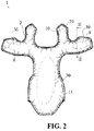
Figure 2 shows a plan view of the protective device ofFigure 1 ; -
Figure 3a shows a section of the device ofFigure 2 according to the line III ofFigure 2 according to a first embodiment; -
Figure 3b shows a section of the device ofFigure 2 according to the line III ofFigure 2 according to a second embodiment. - With reference to the attached figures, the
reference number 1 indicates a personal protective device according to the present invention according to a first embodiment. In particular, the protective device comprises aninflatable element 2 shaped like a casing and wherein an inner chamber 3 is defined. Theinflatable element 2 is apt to substantially assume a first rest condition or deflated condition, and a second active condition or inflated condition. The inflating modes of theinflatable element 2 will be described in the following description. - In the illustrated embodiment, the
inflatable element 2 is suitably shaped to be placed on the upper part of a user's bust. For this purpose, the shape of theinflatable element 2 has twoside wings spinal portion 11, intended to protect the user's backbone. A gas generator not visible in the drawings is included in thespinal portion 11 of the inflatable member. - The inflatable element 12 can be made according to the technology described in the patent application
PCT/IB2009/055512 and in the patent applicationPCT/ IT2009/000547 EP3167730A1 . - The
protective device 1 comprises a plurality oftie elements 5 distributed in the inner chamber 3 and permanently connected to respective portions of theinflatable element 2. Theterm tie element 5 refers to an element or entity, being tensioned, intended for keeping together or fasten or firm two or more parts of theinflatable element 2, at least when the latter is in an inflated condition. - In the example, the
tie elements 5 are thread-like, and are flexible and inextensible elements. Therefore, they are appropriately sized so that, when theinflatable element 2 is in the rest condition, they are preferably not tensioned and are collapsed in the inner chamber 3, whereas when theinflatable element 2 is in an inflated condition they are tensioned. Alternatively, thetie elements 5 may be elastic or yielding threads, i.e. threads that, if subjected to a tensioning action, as during the inflated condition, extend or elongate until a maximum length is reached. - The inflatable element comprises
opposite walls edges inflatable element 2 comprisesmeshes wall mesh respective wall inflatable element 2 has a substantially double-valve structure, wherein each valve corresponds to awall meshes walls respective wall - According to an aspect of the present invention, the
inflatable element 2 includes one or more operativeprotective region 30. The operativeprotective region 30 is the region that, in an inflated condition during an impact test, in a certification device, is centered on an anvil and is exposed to a striking body. The inflatable element also has a peripheral zone orboundary zone 32 being along at least a part of protective operating region perimeter, between the latter and thefree edge - The peripheral zone or
boundary zone 32 has a greater height than theprotective operating region 30 when theinflatable element 2 is in the active inflated condition. - It is possible that only a portion of the
operative zone 30 is surrounded by the boundary orperipheral zone 32. In other words, the boundary zone orperipheral zone 32 contours at least partly theprotective operating region 30. For example, the boundary or peripheral 32 surrounds or encircles at least 50%, preferably from 50% to 80% of the central zone orprotective operating zone 30. - The different height can be obtained by using textile structures with inextensible threads of different lengths as described in the patent application
PCT/IB2009/055512 and in the aforementionedPCT/IT2009/000547 peripheral zone 32 the threads or tieelements 5 may be longer than the threads of theoperative zone 30. - The knitting machine can also be set for varying the type of joining
threads 5 according to the portion of theprotective device 1 where they are located. Thus,threads 5 of different materials, preferably made of elastic or yielding materials, and being or not of the same length, can be used at the peripheral orboundary zone 32 and/or at theoperative zone 30. For example, threads or tieelements 5 having the same length can be made of elastic or yielding material at the boundary orperipheral zone 32 while the threads or tieelements 5 at theoperative area 30 are made of inextensible material. Or,threads 5 made of a more elastic or more yielding material, i.e. with a greater tendency to deformation and then elongation, can be used for the boundary orperipheral zone 32 and less elastic or yieldingthreads 5 for theprotective operating zone 30. In both cases, when theinflatable element 2 assumes the active inflated position,threads 5 of the boundary orperipheral zone 32 will have to be longer than thethreads 5 used in theoperative zone 30. - However, as anticipated, the boundary zone or
peripheral zone 32 thus has a height or thickness greater than the height or thickness of theprotective operating region 30 when theinflatable element 2 is inflated. - With reference to
Figure 2B , a personalprotective device 100, made according to a construction technique different from that of the previous embodiment, is described below. - Elements and parts of this second embodiment having the same function and the same structure of the elements and parts of the previously described embodiment are indicated with the same reference number and are not described in detail once again.
- In the embodiment of
Figure 2B , theinflatable element 102 includes aknitted body 103, having the same function as the twomeshes knitted body 103 is a substantially pouch body, such as that described in the international applicationPCT/IB2016/052510 . - The
knitted body 103 therefore includes, when lain on a plane and flattened in this extended position, two opposed portions orwalls lateral portions Figure 3b , extending seamlessly between the two opposingportions - Thanks to the tubular shape, and even better thanks to the bag-shaped or closed-casing shape, the
knitted body 103 has the advantage of being closed laterally on at least two sides (at theside portions inflatable element 102free edges - The
inflatable element 102 is also shaped with twoside wings spinal portion 11, intended to protect the user's backbone. Theknitted body 103 is shaped to follow the shape of theinflatable element 102, and is made in a single-body according to said shape so as to define a singleinner area 104. - The
knitted body 103 further includes a plurality of joiningthreads 105 or tie threads distributed in theinner chamber 104 and firmly connected to therespective portions knitted body 103, in particular to surface portions thereof. Theknitted body 103 with the joiningthreads 105 corresponds, by function, to the textile structure above described. The joiningthreads 105 have the same function as the tie elements above mentioned. - The
knitted body 103 can also be coated and covered with a covering. The cover may include twowalls perimetric edges - The
walls - According to an aspect of the present invention, the
inflatable member 102 includes aprotective operating region 130. Theprotective operating region 130 is that region which, during an impact test in a certification device, is centred on an anvil in inflated condition and exposed to a striking body. Theprotective operating region 130 is moved with respect to the anvil to be completely hit by the striking body. - The
inflatable member 102 further includes a peripheral zone orboundary zone 132 which at least partially surrounds theprotective operating region 130 and is interposed between theprotective operating region 130 and theinflatable member edge - The peripheral or
boundary zone 132 may be a zone that completely surrounds thecentral area 130, or which extends for some portions of theprotective operating region 130, where the latter is close to theinflatable element edge boundary zone 132 has a greater height than theprotective operating region 130 when theinflatable element 102 assumes the active inflated condition. - As for the previous embodiment, it is possible that the boundary zone or
peripheral zone 132 only partially surrounds theprotective operating region 130. For example at least 50%, even more preferably between 50% and 80%, of the central zone orprotective zone 130 is surrounded or encircled by the boundary zone orperipheral zone 132. - A method for making a knitted body such as the one above described provides, for example, using a so-called three-dimensional knitting machine known to a person skilled in the art. The fact of using a knitting machine to make a knitted body with the joining threads allows the length of the threads with which the knitted body is made to be calibrated as required. In particular, the knitting machine can be set for varying the length and density of the joining threads according to the portion of the protective device where they are located. It follows that the aforementioned
protective operating region 130 and peripheral orboundary zone 132 can be made with joiningthreads 105 of different length. In particular, in said boundary zone orperipheral zone 132 the threads or tieelements 105 may be longer than the threads of theoperating area 130. - The knitting machine can also be set for varying the type of joining
threads 105 according to the portion of theprotective device 100 where they are located. Therefore,threads 105 of different materials, preferably made of elastic or yielding materials, and having or not the same length, can be used at the peripheral orboundary zone 132 and/or at theoperative zone 130. For example, threads or tieelements 105 having the same length can be made of elastic or yielding material at the boundary orperipheral zone 132 while the threads or tieelements 105 at theoperative area 130 are made of inextensible material. Or, more elastic or moreyielding threads 105, i.e. with a greater tendency to deformation then to elongation, can be used for the boundary orperipheral zone 132 and less elastic or lessyielding threads 105 for theprotective operating zone 130. In both cases, when theinflatable element 102 assumes the active inflated position, thethreads 105 of the boundary orperipheral zone 132 will have to be longer than thethreads 105 used in theoperative zone 130. - However, as anticipated, the boundary zone or
peripheral zone 132 thus has a height or thickness greater than the height or thickness of theprotective operating region 130 when theinflatable element 102 is inflated. It can be understood that by moving theprotective operating region higher border region - In order to carry out the inflation of the
inflatable element protective device inflatable element - Alternatively, such inflation means may comprise pyrotechnic or hybrid type gas generators or other types known to the state of the art.
- These inflation means are controlled by a control unit based on the detection of the state of the vehicle/pilot system; for example said control unit can implement a fall prediction system that allows a timely identification of the fall event and a reliable prediction of this by means of accelerometric sensors integral with the vehicle (or the pilot) and a processing unit of the signals produced by the sensors themselves.
- Alternatively, the device according to the present invention can also be applied using an activation cable connected to a vehicle driven by a user, which cable controls the inflation of the
inflatable element - In any case, the aforesaid activation and inflation means can be integrated into the
protective device - It should also be noted that the activation modes, although being of particular relevance for an effective operation of the device, will not be further described in greater detail since being modes essentially already known to an expert in the field of protection of an individual from unexpected impacts.
- The
protective device element - It is further noted that the
protective device - In order to make the knitted body waterproof or at least temporarily waterproof, it is possible to provide a localized covering of the knitted body, or the creation of a thicker mesh at the knitted body.
- Two covering layers may be provided on opposite sides of the knitted body, and said covering layers may be joined through appropriate openings provided around the knitted body.
- The object of the present invention has been described up to now with reference to preferred embodiments. It is to be understood that other embodiments may exist which belong to the same inventive core, all of which are within the scope of the protection of the appended claims hereafter.
Claims (15)
- Wearable protective device (1, 100) for the personal protection of a user, said protective device comprising an inflatable element (2, 102) in which an inner chamber (3, 104) is defined, the inflatable element including a plurality of tie elements (5, 105) distributed in the inner chamber (3, 104) and having opposite ends connected with or joined to surface portions of the inflatable element, wherein said inflatable element (2, 102) is suitable for assuming an active inflated condition and a deflated rest condition; said protective device comprising a protective operating region (30, 130) for protecting a corresponding portion of a user's body wherein said inflatable element comprises a boundary or peripheral zone (32, 132) interposed between at least a portion of the protective operating region (30, 130) and an adjacent free edge zone (20, 21) of the inflatable element (2, 102);
and wherein said boundary or peripheral zone (32, 132), when the inflatable element is in said active inflated condition, has a height or thickness higher than the height or thickness of the protective operating region (30, 130);
and characterised in that said boundary or peripheral zone (32, 132) surrounds at least 50% of the protective operating region (30, 130). - Wearable protective device (1, 100) according to claim 1, wherein a protective operating region (30, 130) is an area intended for establishing certification of protection.
- Wearable protective device (1, 100) according to claim 1 or 2, wherein said adjacent free edge zone (20, 21) of the inflatable element (2, 102) is an area not intended for establishing certification of protection.
- Wearable protective device (1, 100) according to any one of the preceding claims, wherein the length of the tie elements (5, 105) is correlated to the boundary or peripheral zone (32, 132) height or to the protective operating region (30, 130) height.
- Wearable protective device (1, 100) according to claim 4, wherein the tie elements (5, 105) in the boundary zone or peripheral zone (32, 132) have greater length than the tie elements (5, 105) of the protective operating area (30, 130).
- Wearable protective device (1, 100) according to any one of the preceding claims, wherein the boundary or peripheral zone (32, 132) surrounds at least from 50% to 80% of the protective operating region (30).
- Wearable protective device (1, 100) according to any one of the preceding claims, wherein the boundary or peripheral zone (32, 132) completely surrounds the protective operating region (30).
- Wearable protective device (1, 100) according to any one of the preceding claims, wherein the protective operating region (30) is a portion of an inflatable element intended to protect a user's shoulder, a portion of an inflatable element intended for protecting a user's back of and/or a portion of inflatable element intended to protect a user's chest.
- Garment including a protective device (1, 100) according to any one of the preceding claims from 1 to 8.
- Method for performing an impact test on an inflatable element (2, 102) of a wearable protective device (1, 100) for a user's personal protection, wherein the test is performed by means of a striking hitting body or hammer, the method provides for:- providing an inflatable element (2, 102) in which an inner chamber (3, 104) is defined, the inflatable element including a plurality of tie elements (5, 105) distributed in the inner chamber (3, 104) and having opposite ends connected with or joined to surface portions of the inflatable element, wherein the inflatable element includes a protective operating region and a boundary or peripheral zone (32, 132) interposed between a portion of the protective operating region (30, 130) and a free edge zone (20, 21) of the inflatable element (2, 102), and wherein in an active inflated condition said boundary or peripheral zone (32, 132) has a height or thickness greater than the height or thickness of the protective operating region (30, 130) and characterised in that said boundary or peripheral zone (32, 132) surrounds at least 50% of the protective operating region (30, 130), and in that said method further provides for:- inflating the inflatable element (2, 102);- positioning the inflatable element (2, 102) on an anvil so that a superficial portion or face of the inflatable element (2, 102) is laid on the anvil;- hitting the other surface portion of the inflatable element with the hammer on the protective operating region (30, 130) of the inflatable element (2, 102) as well as on the boundary or peripheral zone (32,132).
- Method according to claim 10, wherein during the impact test, the inflatable element (2, 102) is moved so that an edge of the inflatable element is brought closer to the anvil and the hammer.
- Method according to claim 10 or 11, wherein the protective operating region (30, 130) is an area intended for establishing certification of protection by means of the impact test.
- Method according to any one of the preceding claims 10 to 12, wherein said adjacent free edge zone (20, 21) of the inflatable element (2, 102) is an area not intended for establishing certification of protection.
- Method according to any one of the preceding claims 10 to 13, wherein the boundary or peripheral zone (32, 132) surrounds at least from 50% to 80% of the protective operating region (30, 130).
- Method according to any one of the preceding claims 10 to 14, wherein the boundary or peripheral zone (32, 132) completely surrounds the protective operating region (30, 130).
Applications Claiming Priority (1)
| Application Number | Priority Date | Filing Date | Title |
|---|---|---|---|
| IT102017000070699A IT201700070699A1 (en) | 2017-06-23 | 2017-06-23 | PROTECTION DEVICE |
Publications (2)
| Publication Number | Publication Date |
|---|---|
| EP3417730A1 EP3417730A1 (en) | 2018-12-26 |
| EP3417730B1 true EP3417730B1 (en) | 2020-04-22 |
Family
ID=60182984
Family Applications (1)
| Application Number | Title | Priority Date | Filing Date |
|---|---|---|---|
| EP18179292.0A Active EP3417730B1 (en) | 2017-06-23 | 2018-06-22 | Protection device and method for performing an impact test on such a protection device |
Country Status (2)
| Country | Link |
|---|---|
| EP (1) | EP3417730B1 (en) |
| IT (1) | IT201700070699A1 (en) |
Families Citing this family (1)
| Publication number | Priority date | Publication date | Assignee | Title |
|---|---|---|---|---|
| CN112013069B (en) * | 2019-05-31 | 2022-09-30 | 通用汽车环球科技运作有限责任公司 | Expandable structural member |
Family Cites Families (8)
| Publication number | Priority date | Publication date | Assignee | Title |
|---|---|---|---|---|
| US5083361A (en) * | 1988-02-05 | 1992-01-28 | Robert C. Bogert | Pressurizable envelope and method |
| US5152018A (en) * | 1989-12-15 | 1992-10-06 | Cascade Designs, Inc. | Batting filled self inflatable body |
| US8151486B2 (en) * | 2008-05-20 | 2012-04-10 | Nike, Inc. | Fluid-filled chamber with a textile tensile member |
| US8608191B2 (en) * | 2008-12-09 | 2013-12-17 | Dainese S.P.A. | Protection device including an inflatable member |
| US20160073707A1 (en) * | 2013-05-06 | 2016-03-17 | Dainese S.P.A. | Personal protection device |
| ITVR20150074A1 (en) | 2015-05-06 | 2016-11-06 | Dainese Spa | PROTECTIVE DEVICE AND METHOD FOR REALIZING THIS PROTECTIVE DEVICE |
| US9663062B2 (en) * | 2015-10-16 | 2017-05-30 | Autoliv Asp, Inc. | Airbags including internal tethers and methods of forming the same |
| ITUB20155497A1 (en) | 2015-11-11 | 2017-05-11 | Dainese Spa | PROTECTION DEVICE |
-
2017
- 2017-06-23 IT IT102017000070699A patent/IT201700070699A1/en unknown
-
2018
- 2018-06-22 EP EP18179292.0A patent/EP3417730B1/en active Active
Non-Patent Citations (1)
| Title |
|---|
| None * |
Also Published As
| Publication number | Publication date |
|---|---|
| IT201700070699A1 (en) | 2018-12-23 |
| EP3417730A1 (en) | 2018-12-26 |
Similar Documents
| Publication | Publication Date | Title |
|---|---|---|
| EP3007573B1 (en) | Personal protection device | |
| US12121083B2 (en) | Standalone wearable protector and protective clothing assembly | |
| US10165806B2 (en) | Systems for active coupling of airbags | |
| CA2990314C (en) | Helmet | |
| JP3135924B2 (en) | Trousers with hip protector | |
| EP2502794B1 (en) | A pedestrian airbag arrangement | |
| KR20140024974A (en) | Airbag system for motorcycle drivers | |
| KR102871881B1 (en) | Wearable protective devices | |
| JPH11222097A (en) | Occupant protecting device from shock in vehicle having inflatable gas bag | |
| JPH11222098A (en) | Impact protective device for vehicle occupant having expansible gas bag | |
| CN212520868U (en) | Integrated air bag garment | |
| JP2012511637A (en) | Body protection devices and clothes incorporating such devices | |
| KR20210102303A (en) | Garments containing inflatable protective devices | |
| EP3662772A1 (en) | Garment with an inflatable protective device | |
| EP3417730A1 (en) | Protection device and method for performing an impact test on such a protection device | |
| EP3795020A1 (en) | Protection device and process for manufacturing such protection device | |
| CN210726734U (en) | Inflatable trousers for preventing tumble injury of old people | |
| EP3007572B1 (en) | Personal protection device | |
| EP3482646B1 (en) | Knee protection device | |
| EP3795019A1 (en) | Protection device and process for manufacturing such protection device | |
| EP2862754B1 (en) | A safety device | |
| EP4364599B1 (en) | Personal protection device | |
| EP3649879B1 (en) | Personal protective device and garment including said protective device | |
| EP3912498B1 (en) | Garment including a protection device | |
| WO2026094943A1 (en) | Protection device and protection method |
Legal Events
| Date | Code | Title | Description |
|---|---|---|---|
| PUAI | Public reference made under article 153(3) epc to a published international application that has entered the european phase |
Free format text: ORIGINAL CODE: 0009012 |
|
| STAA | Information on the status of an ep patent application or granted ep patent |
Free format text: STATUS: THE APPLICATION HAS BEEN PUBLISHED |
|
| AK | Designated contracting states |
Kind code of ref document: A1 Designated state(s): AL AT BE BG CH CY CZ DE DK EE ES FI FR GB GR HR HU IE IS IT LI LT LU LV MC MK MT NL NO PL PT RO RS SE SI SK SM TR |
|
| AX | Request for extension of the european patent |
Extension state: BA ME |
|
| STAA | Information on the status of an ep patent application or granted ep patent |
Free format text: STATUS: REQUEST FOR EXAMINATION WAS MADE |
|
| RAP1 | Party data changed (applicant data changed or rights of an application transferred) |
Owner name: DAINESE S.P.A. |
|
| 17P | Request for examination filed |
Effective date: 20190620 |
|
| RBV | Designated contracting states (corrected) |
Designated state(s): AL AT BE BG CH CY CZ DE DK EE ES FI FR GB GR HR HU IE IS IT LI LT LU LV MC MK MT NL NO PL PT RO RS SE SI SK SM TR |
|
| RAP1 | Party data changed (applicant data changed or rights of an application transferred) |
Owner name: DAINESE S.P.A. |
|
| GRAP | Despatch of communication of intention to grant a patent |
Free format text: ORIGINAL CODE: EPIDOSNIGR1 |
|
| STAA | Information on the status of an ep patent application or granted ep patent |
Free format text: STATUS: GRANT OF PATENT IS INTENDED |
|
| RIC1 | Information provided on ipc code assigned before grant |
Ipc: B32B 1/08 20060101ALI20191022BHEP Ipc: A41D 13/05 20060101ALI20191022BHEP Ipc: A63B 71/12 20060101ALI20191022BHEP Ipc: D04B 1/22 20060101ALI20191022BHEP Ipc: B32B 3/08 20060101ALI20191022BHEP Ipc: A63B 71/08 20060101ALN20191022BHEP Ipc: B62J 27/00 20060101ALN20191022BHEP Ipc: B32B 5/14 20060101ALI20191022BHEP Ipc: B32B 5/02 20060101ALI20191022BHEP Ipc: A41D 31/00 20190101ALN20191022BHEP Ipc: A41D 13/018 20060101AFI20191022BHEP Ipc: B32B 5/22 20060101ALI20191022BHEP Ipc: B32B 7/12 20060101ALI20191022BHEP Ipc: B32B 5/08 20060101ALI20191022BHEP Ipc: B32B 5/26 20060101ALI20191022BHEP Ipc: D04B 1/24 20060101ALI20191022BHEP Ipc: B60R 21/2338 20110101ALN20191022BHEP |
|
| INTG | Intention to grant announced |
Effective date: 20191111 |
|
| GRAS | Grant fee paid |
Free format text: ORIGINAL CODE: EPIDOSNIGR3 |
|
| GRAA | (expected) grant |
Free format text: ORIGINAL CODE: 0009210 |
|
| STAA | Information on the status of an ep patent application or granted ep patent |
Free format text: STATUS: THE PATENT HAS BEEN GRANTED |
|
| AK | Designated contracting states |
Kind code of ref document: B1 Designated state(s): AL AT BE BG CH CY CZ DE DK EE ES FI FR GB GR HR HU IE IS IT LI LT LU LV MC MK MT NL NO PL PT RO RS SE SI SK SM TR |
|
| REG | Reference to a national code |
Ref country code: CH Ref legal event code: EP |
|
| REG | Reference to a national code |
Ref country code: DE Ref legal event code: R096 Ref document number: 602018003925 Country of ref document: DE |
|
| REG | Reference to a national code |
Ref country code: IE Ref legal event code: FG4D |
|
| REG | Reference to a national code |
Ref country code: AT Ref legal event code: REF Ref document number: 1258900 Country of ref document: AT Kind code of ref document: T Effective date: 20200515 |
|
| REG | Reference to a national code |
Ref country code: CH Ref legal event code: PK Free format text: BERICHTIGUNGEN |
|
| RIN2 | Information on inventor provided after grant (corrected) |
Inventor name: LANARO, CLAUDIO Inventor name: ZANOTTO, STEFANO |
|
| REG | Reference to a national code |
Ref country code: LT Ref legal event code: MG4D |
|
| REG | Reference to a national code |
Ref country code: NL Ref legal event code: MP Effective date: 20200422 |
|
| PG25 | Lapsed in a contracting state [announced via postgrant information from national office to epo] |
Ref country code: NL Free format text: LAPSE BECAUSE OF FAILURE TO SUBMIT A TRANSLATION OF THE DESCRIPTION OR TO PAY THE FEE WITHIN THE PRESCRIBED TIME-LIMIT Effective date: 20200422 Ref country code: LT Free format text: LAPSE BECAUSE OF FAILURE TO SUBMIT A TRANSLATION OF THE DESCRIPTION OR TO PAY THE FEE WITHIN THE PRESCRIBED TIME-LIMIT Effective date: 20200422 Ref country code: PT Free format text: LAPSE BECAUSE OF FAILURE TO SUBMIT A TRANSLATION OF THE DESCRIPTION OR TO PAY THE FEE WITHIN THE PRESCRIBED TIME-LIMIT Effective date: 20200824 Ref country code: GR Free format text: LAPSE BECAUSE OF FAILURE TO SUBMIT A TRANSLATION OF THE DESCRIPTION OR TO PAY THE FEE WITHIN THE PRESCRIBED TIME-LIMIT Effective date: 20200723 Ref country code: SE Free format text: LAPSE BECAUSE OF FAILURE TO SUBMIT A TRANSLATION OF THE DESCRIPTION OR TO PAY THE FEE WITHIN THE PRESCRIBED TIME-LIMIT Effective date: 20200422 Ref country code: NO Free format text: LAPSE BECAUSE OF FAILURE TO SUBMIT A TRANSLATION OF THE DESCRIPTION OR TO PAY THE FEE WITHIN THE PRESCRIBED TIME-LIMIT Effective date: 20200722 Ref country code: IS Free format text: LAPSE BECAUSE OF FAILURE TO SUBMIT A TRANSLATION OF THE DESCRIPTION OR TO PAY THE FEE WITHIN THE PRESCRIBED TIME-LIMIT Effective date: 20200822 Ref country code: FI Free format text: LAPSE BECAUSE OF FAILURE TO SUBMIT A TRANSLATION OF THE DESCRIPTION OR TO PAY THE FEE WITHIN THE PRESCRIBED TIME-LIMIT Effective date: 20200422 |
|
| REG | Reference to a national code |
Ref country code: AT Ref legal event code: MK05 Ref document number: 1258900 Country of ref document: AT Kind code of ref document: T Effective date: 20200422 |
|
| PG25 | Lapsed in a contracting state [announced via postgrant information from national office to epo] |
Ref country code: RS Free format text: LAPSE BECAUSE OF FAILURE TO SUBMIT A TRANSLATION OF THE DESCRIPTION OR TO PAY THE FEE WITHIN THE PRESCRIBED TIME-LIMIT Effective date: 20200422 Ref country code: LV Free format text: LAPSE BECAUSE OF FAILURE TO SUBMIT A TRANSLATION OF THE DESCRIPTION OR TO PAY THE FEE WITHIN THE PRESCRIBED TIME-LIMIT Effective date: 20200422 Ref country code: HR Free format text: LAPSE BECAUSE OF FAILURE TO SUBMIT A TRANSLATION OF THE DESCRIPTION OR TO PAY THE FEE WITHIN THE PRESCRIBED TIME-LIMIT Effective date: 20200422 Ref country code: BG Free format text: LAPSE BECAUSE OF FAILURE TO SUBMIT A TRANSLATION OF THE DESCRIPTION OR TO PAY THE FEE WITHIN THE PRESCRIBED TIME-LIMIT Effective date: 20200722 |
|
| PG25 | Lapsed in a contracting state [announced via postgrant information from national office to epo] |
Ref country code: AL Free format text: LAPSE BECAUSE OF FAILURE TO SUBMIT A TRANSLATION OF THE DESCRIPTION OR TO PAY THE FEE WITHIN THE PRESCRIBED TIME-LIMIT Effective date: 20200422 |
|
| REG | Reference to a national code |
Ref country code: DE Ref legal event code: R097 Ref document number: 602018003925 Country of ref document: DE |
|
| PG25 | Lapsed in a contracting state [announced via postgrant information from national office to epo] |
Ref country code: EE Free format text: LAPSE BECAUSE OF FAILURE TO SUBMIT A TRANSLATION OF THE DESCRIPTION OR TO PAY THE FEE WITHIN THE PRESCRIBED TIME-LIMIT Effective date: 20200422 Ref country code: SM Free format text: LAPSE BECAUSE OF FAILURE TO SUBMIT A TRANSLATION OF THE DESCRIPTION OR TO PAY THE FEE WITHIN THE PRESCRIBED TIME-LIMIT Effective date: 20200422 Ref country code: AT Free format text: LAPSE BECAUSE OF FAILURE TO SUBMIT A TRANSLATION OF THE DESCRIPTION OR TO PAY THE FEE WITHIN THE PRESCRIBED TIME-LIMIT Effective date: 20200422 Ref country code: RO Free format text: LAPSE BECAUSE OF FAILURE TO SUBMIT A TRANSLATION OF THE DESCRIPTION OR TO PAY THE FEE WITHIN THE PRESCRIBED TIME-LIMIT Effective date: 20200422 Ref country code: CZ Free format text: LAPSE BECAUSE OF FAILURE TO SUBMIT A TRANSLATION OF THE DESCRIPTION OR TO PAY THE FEE WITHIN THE PRESCRIBED TIME-LIMIT Effective date: 20200422 Ref country code: ES Free format text: LAPSE BECAUSE OF FAILURE TO SUBMIT A TRANSLATION OF THE DESCRIPTION OR TO PAY THE FEE WITHIN THE PRESCRIBED TIME-LIMIT Effective date: 20200422 Ref country code: MC Free format text: LAPSE BECAUSE OF FAILURE TO SUBMIT A TRANSLATION OF THE DESCRIPTION OR TO PAY THE FEE WITHIN THE PRESCRIBED TIME-LIMIT Effective date: 20200422 Ref country code: DK Free format text: LAPSE BECAUSE OF FAILURE TO SUBMIT A TRANSLATION OF THE DESCRIPTION OR TO PAY THE FEE WITHIN THE PRESCRIBED TIME-LIMIT Effective date: 20200422 |
|
| PG25 | Lapsed in a contracting state [announced via postgrant information from national office to epo] |
Ref country code: SK Free format text: LAPSE BECAUSE OF FAILURE TO SUBMIT A TRANSLATION OF THE DESCRIPTION OR TO PAY THE FEE WITHIN THE PRESCRIBED TIME-LIMIT Effective date: 20200422 Ref country code: PL Free format text: LAPSE BECAUSE OF FAILURE TO SUBMIT A TRANSLATION OF THE DESCRIPTION OR TO PAY THE FEE WITHIN THE PRESCRIBED TIME-LIMIT Effective date: 20200422 |
|
| PLBE | No opposition filed within time limit |
Free format text: ORIGINAL CODE: 0009261 |
|
| STAA | Information on the status of an ep patent application or granted ep patent |
Free format text: STATUS: NO OPPOSITION FILED WITHIN TIME LIMIT |
|
| 26N | No opposition filed |
Effective date: 20210125 |
|
| PG25 | Lapsed in a contracting state [announced via postgrant information from national office to epo] |
Ref country code: LU Free format text: LAPSE BECAUSE OF NON-PAYMENT OF DUE FEES Effective date: 20200622 |
|
| REG | Reference to a national code |
Ref country code: BE Ref legal event code: MM Effective date: 20200630 |
|
| PG25 | Lapsed in a contracting state [announced via postgrant information from national office to epo] |
Ref country code: IE Free format text: LAPSE BECAUSE OF NON-PAYMENT OF DUE FEES Effective date: 20200622 |
|
| PG25 | Lapsed in a contracting state [announced via postgrant information from national office to epo] |
Ref country code: BE Free format text: LAPSE BECAUSE OF NON-PAYMENT OF DUE FEES Effective date: 20200630 Ref country code: SI Free format text: LAPSE BECAUSE OF FAILURE TO SUBMIT A TRANSLATION OF THE DESCRIPTION OR TO PAY THE FEE WITHIN THE PRESCRIBED TIME-LIMIT Effective date: 20200422 |
|
| REG | Reference to a national code |
Ref country code: CH Ref legal event code: PL |
|
| PG25 | Lapsed in a contracting state [announced via postgrant information from national office to epo] |
Ref country code: LI Free format text: LAPSE BECAUSE OF NON-PAYMENT OF DUE FEES Effective date: 20210630 Ref country code: CH Free format text: LAPSE BECAUSE OF NON-PAYMENT OF DUE FEES Effective date: 20210630 |
|
| PG25 | Lapsed in a contracting state [announced via postgrant information from national office to epo] |
Ref country code: TR Free format text: LAPSE BECAUSE OF FAILURE TO SUBMIT A TRANSLATION OF THE DESCRIPTION OR TO PAY THE FEE WITHIN THE PRESCRIBED TIME-LIMIT Effective date: 20200422 Ref country code: MT Free format text: LAPSE BECAUSE OF FAILURE TO SUBMIT A TRANSLATION OF THE DESCRIPTION OR TO PAY THE FEE WITHIN THE PRESCRIBED TIME-LIMIT Effective date: 20200422 Ref country code: CY Free format text: LAPSE BECAUSE OF FAILURE TO SUBMIT A TRANSLATION OF THE DESCRIPTION OR TO PAY THE FEE WITHIN THE PRESCRIBED TIME-LIMIT Effective date: 20200422 |
|
| PG25 | Lapsed in a contracting state [announced via postgrant information from national office to epo] |
Ref country code: MK Free format text: LAPSE BECAUSE OF FAILURE TO SUBMIT A TRANSLATION OF THE DESCRIPTION OR TO PAY THE FEE WITHIN THE PRESCRIBED TIME-LIMIT Effective date: 20200422 |
|
| PGFP | Annual fee paid to national office [announced via postgrant information from national office to epo] |
Ref country code: GB Payment date: 20230622 Year of fee payment: 6 |
|
| GBPC | Gb: european patent ceased through non-payment of renewal fee |
Effective date: 20240622 |
|
| PG25 | Lapsed in a contracting state [announced via postgrant information from national office to epo] |
Ref country code: GB Free format text: LAPSE BECAUSE OF NON-PAYMENT OF DUE FEES Effective date: 20240622 |
|
| PGFP | Annual fee paid to national office [announced via postgrant information from national office to epo] |
Ref country code: DE Payment date: 20250618 Year of fee payment: 8 |
|
| PGFP | Annual fee paid to national office [announced via postgrant information from national office to epo] |
Ref country code: FR Payment date: 20250625 Year of fee payment: 8 |
|
| PGFP | Annual fee paid to national office [announced via postgrant information from national office to epo] |
Ref country code: IT Payment date: 20250609 Year of fee payment: 8 |