EP3417266B1 - Single-piece transfer arm structure and mounting clamp for analytical instrumentation - Google Patents
Single-piece transfer arm structure and mounting clamp for analytical instrumentation Download PDFInfo
- Publication number
- EP3417266B1 EP3417266B1 EP17753784.2A EP17753784A EP3417266B1 EP 3417266 B1 EP3417266 B1 EP 3417266B1 EP 17753784 A EP17753784 A EP 17753784A EP 3417266 B1 EP3417266 B1 EP 3417266B1
- Authority
- EP
- European Patent Office
- Prior art keywords
- transfer arm
- elongated
- rigid member
- probe
- top surface
- Prior art date
- Legal status (The legal status is an assumption and is not a legal conclusion. Google has not performed a legal analysis and makes no representation as to the accuracy of the status listed.)
- Active
Links
Images




Classifications
-
- G—PHYSICS
- G01—MEASURING; TESTING
- G01N—INVESTIGATING OR ANALYSING MATERIALS BY DETERMINING THEIR CHEMICAL OR PHYSICAL PROPERTIES
- G01N35/00—Automatic analysis not limited to methods or materials provided for in any single one of groups G01N1/00 - G01N33/00; Handling materials therefor
- G01N35/10—Devices for transferring samples or any liquids to, in, or from, the analysis apparatus, e.g. suction devices, injection devices
- G01N35/1009—Characterised by arrangements for controlling the aspiration or dispense of liquids
- G01N35/1011—Control of the position or alignment of the transfer device
-
- A—HUMAN NECESSITIES
- A61—MEDICAL OR VETERINARY SCIENCE; HYGIENE
- A61B—DIAGNOSIS; SURGERY; IDENTIFICATION
- A61B17/00—Surgical instruments, devices or methods
-
- B—PERFORMING OPERATIONS; TRANSPORTING
- B01—PHYSICAL OR CHEMICAL PROCESSES OR APPARATUS IN GENERAL
- B01L—CHEMICAL OR PHYSICAL LABORATORY APPARATUS FOR GENERAL USE
- B01L3/00—Containers or dishes for laboratory use, e.g. laboratory glassware; Droppers
- B01L3/02—Burettes; Pipettes
-
- B—PERFORMING OPERATIONS; TRANSPORTING
- B26—HAND CUTTING TOOLS; CUTTING; SEVERING
- B26D—CUTTING; DETAILS COMMON TO MACHINES FOR PERFORATING, PUNCHING, CUTTING-OUT, STAMPING-OUT OR SEVERING
- B26D1/00—Cutting through work characterised by the nature or movement of the cutting member or particular materials not otherwise provided for; Apparatus or machines therefor; Cutting members therefor
-
- B—PERFORMING OPERATIONS; TRANSPORTING
- B60—VEHICLES IN GENERAL
- B60S—SERVICING, CLEANING, REPAIRING, SUPPORTING, LIFTING, OR MANOEUVRING OF VEHICLES, NOT OTHERWISE PROVIDED FOR
- B60S1/00—Cleaning of vehicles
- B60S1/02—Cleaning windscreens, windows or optical devices
- B60S1/04—Wipers or the like, e.g. scrapers
- B60S1/32—Wipers or the like, e.g. scrapers characterised by constructional features of wiper blade arms or blades
- B60S1/40—Connections between blades and arms
-
- G—PHYSICS
- G01—MEASURING; TESTING
- G01B—MEASURING LENGTH, THICKNESS OR SIMILAR LINEAR DIMENSIONS; MEASURING ANGLES; MEASURING AREAS; MEASURING IRREGULARITIES OF SURFACES OR CONTOURS
- G01B21/00—Measuring arrangements or details thereof, where the measuring technique is not covered by the other groups of this subclass, unspecified or not relevant
- G01B21/16—Measuring arrangements or details thereof, where the measuring technique is not covered by the other groups of this subclass, unspecified or not relevant for measuring distance of clearance between spaced objects
-
- G—PHYSICS
- G01—MEASURING; TESTING
- G01F—MEASURING VOLUME, VOLUME FLOW, MASS FLOW OR LIQUID LEVEL; METERING BY VOLUME
- G01F23/00—Indicating or measuring liquid level or level of fluent solid material, e.g. indicating in terms of volume or indicating by means of an alarm
- G01F23/14—Indicating or measuring liquid level or level of fluent solid material, e.g. indicating in terms of volume or indicating by means of an alarm by measurement of pressure
- G01F23/18—Indicating, recording or alarm devices actuated electrically
-
- G—PHYSICS
- G01—MEASURING; TESTING
- G01N—INVESTIGATING OR ANALYSING MATERIALS BY DETERMINING THEIR CHEMICAL OR PHYSICAL PROPERTIES
- G01N1/00—Sampling; Preparing specimens for investigation
-
- G—PHYSICS
- G01—MEASURING; TESTING
- G01N—INVESTIGATING OR ANALYSING MATERIALS BY DETERMINING THEIR CHEMICAL OR PHYSICAL PROPERTIES
- G01N1/00—Sampling; Preparing specimens for investigation
- G01N1/02—Devices for withdrawing samples
- G01N1/10—Devices for withdrawing samples in the liquid or fluent state
-
- G—PHYSICS
- G01—MEASURING; TESTING
- G01N—INVESTIGATING OR ANALYSING MATERIALS BY DETERMINING THEIR CHEMICAL OR PHYSICAL PROPERTIES
- G01N1/00—Sampling; Preparing specimens for investigation
- G01N1/02—Devices for withdrawing samples
- G01N1/10—Devices for withdrawing samples in the liquid or fluent state
- G01N1/14—Suction devices, e.g. pumps; Ejector devices
-
- G—PHYSICS
- G01—MEASURING; TESTING
- G01N—INVESTIGATING OR ANALYSING MATERIALS BY DETERMINING THEIR CHEMICAL OR PHYSICAL PROPERTIES
- G01N1/00—Sampling; Preparing specimens for investigation
- G01N1/28—Preparing specimens for investigation including physical details of (bio-)chemical methods covered elsewhere, e.g. G01N33/50, C12Q
-
- G—PHYSICS
- G01—MEASURING; TESTING
- G01N—INVESTIGATING OR ANALYSING MATERIALS BY DETERMINING THEIR CHEMICAL OR PHYSICAL PROPERTIES
- G01N1/00—Sampling; Preparing specimens for investigation
- G01N1/28—Preparing specimens for investigation including physical details of (bio-)chemical methods covered elsewhere, e.g. G01N33/50, C12Q
- G01N1/38—Diluting, dispersing or mixing samples
-
- G—PHYSICS
- G01—MEASURING; TESTING
- G01N—INVESTIGATING OR ANALYSING MATERIALS BY DETERMINING THEIR CHEMICAL OR PHYSICAL PROPERTIES
- G01N33/00—Investigating or analysing materials by specific methods not covered by groups G01N1/00 - G01N31/00
- G01N33/48—Biological material, e.g. blood, urine; Haemocytometers
-
- G—PHYSICS
- G01—MEASURING; TESTING
- G01N—INVESTIGATING OR ANALYSING MATERIALS BY DETERMINING THEIR CHEMICAL OR PHYSICAL PROPERTIES
- G01N35/00—Automatic analysis not limited to methods or materials provided for in any single one of groups G01N1/00 - G01N33/00; Handling materials therefor
- G01N35/02—Automatic analysis not limited to methods or materials provided for in any single one of groups G01N1/00 - G01N33/00; Handling materials therefor using a plurality of sample containers moved by a conveyor system past one or more treatment or analysis stations
-
- G—PHYSICS
- G01—MEASURING; TESTING
- G01N—INVESTIGATING OR ANALYSING MATERIALS BY DETERMINING THEIR CHEMICAL OR PHYSICAL PROPERTIES
- G01N35/00—Automatic analysis not limited to methods or materials provided for in any single one of groups G01N1/00 - G01N33/00; Handling materials therefor
- G01N35/02—Automatic analysis not limited to methods or materials provided for in any single one of groups G01N1/00 - G01N33/00; Handling materials therefor using a plurality of sample containers moved by a conveyor system past one or more treatment or analysis stations
- G01N35/04—Details of the conveyor system
-
- G—PHYSICS
- G01—MEASURING; TESTING
- G01N—INVESTIGATING OR ANALYSING MATERIALS BY DETERMINING THEIR CHEMICAL OR PHYSICAL PROPERTIES
- G01N35/00—Automatic analysis not limited to methods or materials provided for in any single one of groups G01N1/00 - G01N33/00; Handling materials therefor
- G01N35/10—Devices for transferring samples or any liquids to, in, or from, the analysis apparatus, e.g. suction devices, injection devices
Definitions
- the present invention relates generally to fluid transfer in an in vitro diagnostics environment.
- Clinical analyzers typically utilize transfer arms to position a fluid transfer probe (or needle) and move the probe between fluid aspiration locations (e.g., a reagent container) and fluid dispense locations (e.g., a reaction vessel).
- Multiple transfer arms are typically used to handle various transfers during an analysis of a sample. Often, these transfer arms are radial in nature; they move the probe along a circular arc. For architectural reasons, however, the different transfer arms may require movement of the probe along arcs of varying radii.
- the radial component of the arm provides the structure needed to locate the probe at the correct radius with sufficient stiffness, and it should also be aesthetically pleasing. Achieving the above functions for minimal cost and with minimal number of components has been a challenge.
- US 4344768 B discloses a pipettor apparatus for automatically and rapidly transferring accurate and precise multiple quantities of samples (e.g., blood serum) and reagent to the rotatable transfer disc of a centrifugal analyzer.
- samples e.g., blood serum
- FIGS. 5 and 5a show a pipette tube 202, which is mounted on an arm 203 carried on a rod member 204 which is capable both of rotary movement and longitudinal up and down movement.
- the arm is capable of adjustment by means of a slot 230 in the end of said arm 203 which is clamped by a bolt 231 to allow the position of the pipette to be adjusted.
- US 5304201 A discloses an adjustable clamping device for applying pressure to a puncture site of an artery.
- the clamping device has a radial arm movably supported on a column which extends from a base.
- a carrier movably mounted on the end of the arm supports a pressure pad.
- the radial arm extends in a parallel attitude over the base and may be adjusted vertically upwardly and downwardly in reference to the base and may also be pivoted in reference to the column. Lateral movement of the arm facilitates positioning the pressure pad over the puncture site.
- Previous transfer arm structures have included multiple parts - structural and aesthetic. Some examples include a metallic superstructure covered with a bolt-on thermoplastic aesthetic covering, or a two-piece clam-shell type structure. Additionally, to accommodate multiple arms requiring different radial lengths, unique components have been designed and manufactured. Such designs can be complex and costly.
- the invention is directed to system for a clinical analyzer in an in vitro diagnostics (IVD) environment according to claim 1.
- IVD in vitro diagnostics
- the transfer arm comprises an elongated, rigid member comprising a top surface, a bottom surface, a pivot end and a component end.
- the bottom surface comprises an underside portion of the top surface
- the elongated, rigid member comprises sidewalls extending from the top surface and configured to form at least a partially surrounding enclosure for the bottom surface.
- the pivot end comprises a plurality of radial configuration mounting locations configured to secure a mounting clamp to the elongated, rigid member to couple a shaft to the elongated, rigid member.
- the elongated, rigid member extends horizontally and the shaft is oriented substantially perpendicular to the elongated, rigid member.
- the pivot end comprises a plurality of radial configuration mounting locations to allow for respective ones of radial distances between a pivoting axis at the pivot end and an attached probe at the component end.
- the component end comprises attachment locations for components to be secured to the transfer arm.
- the attachment locations may comprise one or more of (i) one or more access holes extending through the top surface and the bottom surface; and (ii) internal component mounting locations on the bottom surface.
- the components comprise one or more of a probe, a crash detection mechanism, mixing devices, pick-and-place devices, circuit boards, and valves.
- the transfer arm further comprises electromagnetic interference (EMI) shielding material on at least a portion of the bottom surface.
- EMI electromagnetic interference
- the transfer arm further comprises grounding material on at least a portion of the bottom surface.
- the transfer arm comprises structural ribbing formed on the bottom surface, the structural ribbing configured to provide structural support for the elongated, rigid member.
- the elongated, rigid member is injection molded.
- the elongated, rigid member comprises a glass-filled nylon material.
- the transfer arm further comprises one or more alignment ribs formed on an outer portion of the sidewalls.
- the invention is directed to a system for a clinical analyzer in an in vitro diagnostics (IVD) environment comprising a mounting clamp (340) and a single piece transfer arm (100) according to claim 1.
- IVD in vitro diagnostics
- FIGs. 1A and 1B are diagrams illustrating top perspective views of a transfer arm 100.
- FIG. 2 is a diagram illustrating a bottom perspective view of the transfer arm 100 to show an underside view of the transfer arm 100.
- the transfer arm 100 is comprised of a chassis or elongated, rigid member 110 that provides structural and aesthetic properties, acting as both a mounting base and a cover for transfer arm components.
- the elongated, rigid member 110 is a single component, such as a single piece of injection-molded plastic. As shown in FIGs. 1A , 1B , and 2 , the elongated, rigid member 110 has a top surface 120, a bottom or underside surface 130, and sidewalls 140.
- the bottom or underside surface 130 is an underside portion of the top surface 120, and the sidewalls 140 extend from the top surface 120 and form at least a partially surrounding enclosure for the bottom surface 130.
- the elongated, rigid member 110 has a pivot end 112 and a component end 114.
- one or more access holes extend through the top surface 120 and the bottom surface 130 of the elongated, rigid member 110 of the transfer arm 100.
- Access hole 123 is also provided.
- probe access hole 121 and tubing access hole 122 are provided at the component end 114 portion of the elongated, rigid member 110; and access hole 123 is provided near the pivot end 112.
- Other access holes and configurations thereof may be provided depending on use and design factors for which the transfer arm 100 is being utilized.
- an injection gate location 150 is provided.
- the injection gate location 150 provides for symmetric mold flow and limits part warping, while being unobtrusive for the aesthetics of the transfer arm 100.
- Other gate locations that achieve a symmetrical part are possible and may be implemented for the transfer arm 100.
- structural ribbing 132 is formed on the bottom surface 130.
- the size, shape, and location of the structural ribbing 132 is such that it provides structural support for the elongated, rigid member 110. Variations of the structural ribbing 132 shown in FIG. 2 may be used.
- FIG. 3 provides a bottom perspective view of the transfer arm 100 with mounted components mounted via the internal component mounting locations 136.
- Various screws or the like are used to connect the components (e.g., the probe mounting assembly 320 and the printed circuit assembly 330) to the bottom surface 130 via the internal component mounting locations 136.
- FIG. 2 shown are a plurality of radial configuration mounting locations 134 provided on the bottom surface 130 to allow for multiple radial distances between a pivoting axis of the transfer arm 100 (at the pivot end 112) and an attached probe (e.g., probe 310) to accommodate arcs of different radii.
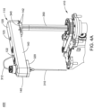
- This concept is illustrated in FIGs. 4A and 4B , which illustrate the transfer arm 100 mounted in a long radial dimension configuration 400 (see FIG. 4A ) and in a short radial dimension configuration 450 (see FIG. 4B ).
- the same component i.e., the transfer arm 100
- a mounting clamp 340 that couples a shaft 350 to the elongated, rigid member 110 is mounted via the radial configuration mounting locations 134.
- FIGs. 4A and 4B also illustrate a drive mechanism or motor controller 410 coupled to the shaft 350 to drive rotational and vertical movement of the transfer arm 100.
- Alignment ribs 142 formed on a portion of sidewalls 140 are provided, according to an embodiment, as markings for use as alignment aids for both gross and fine adjustment (see FIGs. 1A-5 ). In other embodiments, indentations, notches, embossed lettering, and the like may alternatively or additionally be used to indicate alignment position(s).
- FIG. 5 is a diagram 500 illustrating a transfer arm 100 with an externally mounted manifold and valve 510, according to an embodiment.
- the access hole 123 is provided for wires of the manifold and valve 510, which may be mounted using the mounting locations 134 and/or 136.
- FIG. 5 also illustrates the drive mechanism or motor controller 410 coupled to the shaft 350.
- Other devices can also be mounted, according to embodiments, using the mounting locations 134 and/or 136, including, for example and not limitation, a crash detect mechanism, a mixing device, a pick-and-place device, a capacitive level detection printed circuit assembly, other circuit boards, and liquid valves.
- a crash detect mechanism for example and not limitation, a mixing device, a pick-and-place device, a capacitive level detection printed circuit assembly, other circuit boards, and liquid valves.
- Many of these components are contained within the aesthetic enclosure provided by the sidewalls 140. In other words, the components are hidden or at least partially hidden from view, depending on geometries and orientations of the components and/or the transfer arm 100.
- adjustable mounting can take many forms; for example, slots in the transfer arm 100 or a threaded fine adjustment knob. Additional specific or universal mounting points or access holes may be added.
- the material of the transfer arm 100 may be a glass-filled nylon to provide the necessary stiffness and strength.
- the material can be color-matched and textured, as desired, eliminating the need for paint.
- the design of the mold for manufacturing the transfer arm 100 is an important factor in producing a flat part that positions a probe perpendicular to the plane of travel (see FIG. 1B ).
- Other aesthetic properties may include texturing of the upper, outside surfaces (i.e., the top surface 120 and/or the sidewalls 140) of the single-piece transfer arm 100, aesthetically pleasing lines, and surfaces for information labels (e.g., hazard and warning labels).
- an interior portion of the transfer arm 100 may be coated with an electrically conductive paint to provide for electromagnetic interference (EMI) protection (by creating a partial faraday cage) for critical electrical components mounted within.
- EMI electromagnetic interference
- Such a coating may also provide a chassis ground path to the shaft 350 of the arm for a circuit board and other components.
- an interior portion of the transfer arm 100 e.g., a portion of the bottom surface 130 and/or an interior portion of the sidewalls 140
- the transfer arm 100 has an advantage of low cost. This includes the part cost, assembly cost (fewer components), and lower inventory costs for manufacturing and service (again due to fewer components).
- a technical feature that contributes to this lower cost advantage is that the transfer arm 100, according to embodiments herein, is a single part. It is injection molded, which is a low-cost process, and it can be re-used in multiple applications. Savings compared to traditional methods can range from hundreds of thousands to over a million dollars per year, depending on production quantities and on how many products transfer arm 100 is applied.
- FIG. 6 provides a layout of an example system architecture 600 within which embodiments of the invention may be implemented. Shown in FIG. 6 are various transfer arms 100 (100a, 100b, 100c, and 100d) with respective probes; a diluting turntable 620 including a plurality of diluting containers arranged in one or more diluting rings; a reaction turntable 630 including a plurality of reaction containers arranged in one or more reaction rings; and reagent storage areas 640a and 640b dedicated to storage and supply of a respective reagent, each reagent storage area 640a and 640b including a plurality of reagent containers.
- transfer arms 100 100 (100a, 100b, 100c, and 100d) with respective probes
- a diluting turntable 620 including a plurality of diluting containers arranged in one or more diluting rings
- a reaction turntable 630 including a plurality of reaction containers arranged in one or more reaction rings
- reagent storage areas 640a and 640b dedicated to
- transfer arm 100a and its respective probe may operate to transfer sample from an access position to one or more diluting containers on the diluting turntable 620 to create a dilution therein.
- Transfer arm 100b and its respective probe may operate to transfer dilution from a diluting container to a reaction container on the reaction turntable 630.
- Transfer arms 100c and 100d and their respective probes may operate to transfer a reagent from reagent storage area 640a and 640b, respectively, to a reaction container on the reaction turntable 630.
- the various transfers occur by use of a pumping mechanism, such as a displacement pump, for example, attached to the transfer arms 100.
- the system architecture 600 includes one or more controllers for controlling operation of the various components, including the transfer arms 100 (e.g., drive mechanism or motor controller 410), the probes, and the turntables.
- the system architecture 600 of FIG. 6 and the accompanying description are purely exemplary and non-limiting to the single piece radial transfer arm disclosed herein.
- the system architecture 600 is just one example system in which the single piece radial transfer arm may be utilized.
Landscapes
- Physics & Mathematics (AREA)
- Health & Medical Sciences (AREA)
- Life Sciences & Earth Sciences (AREA)
- Chemical & Material Sciences (AREA)
- Analytical Chemistry (AREA)
- Biochemistry (AREA)
- General Health & Medical Sciences (AREA)
- General Physics & Mathematics (AREA)
- Immunology (AREA)
- Pathology (AREA)
- Automatic Analysis And Handling Materials Therefor (AREA)
Description
- The present invention relates generally to fluid transfer in an in vitro diagnostics environment.
- Clinical analyzers typically utilize transfer arms to position a fluid transfer probe (or needle) and move the probe between fluid aspiration locations (e.g., a reagent container) and fluid dispense locations (e.g., a reaction vessel). Multiple transfer arms are typically used to handle various transfers during an analysis of a sample. Often, these transfer arms are radial in nature; they move the probe along a circular arc. For architectural reasons, however, the different transfer arms may require movement of the probe along arcs of varying radii.
The radial component of the arm provides the structure needed to locate the probe at the correct radius with sufficient stiffness, and it should also be aesthetically pleasing. Achieving the above functions for minimal cost and with minimal number of components has been a challenge. -
US 4344768 B discloses a pipettor apparatus for automatically and rapidly transferring accurate and precise multiple quantities of samples (e.g., blood serum) and reagent to the rotatable transfer disc of a centrifugal analyzer. -
US 3883305 A discloses an automatic chemical analysis apparatus having separate closed-looped conveyors for sample and reactant containers. At a fixed location, sample portions from a given sample are transferred to a serial sequence of reactant containers.Figures 5 and 5a show a pipette tube 202, which is mounted on an arm 203 carried on a rod member 204 which is capable both of rotary movement and longitudinal up and down movement. Thus, it is possible for the member 204 to lower the pipette 202 into the sample container 200, raise and then rotate the pipette into a discharge position over the reaction tube 201. The arm is capable of adjustment by means of a slot 230 in the end of said arm 203 which is clamped by a bolt 231 to allow the position of the pipette to be adjusted. -
US 5304201 A discloses an adjustable clamping device for applying pressure to a puncture site of an artery. The clamping device has a radial arm movably supported on a column which extends from a base. A carrier movably mounted on the end of the arm supports a pressure pad. The radial arm extends in a parallel attitude over the base and may be adjusted vertically upwardly and downwardly in reference to the base and may also be pivoted in reference to the column. Lateral movement of the arm facilitates positioning the pressure pad over the puncture site. - Previous transfer arm structures have included multiple parts - structural and aesthetic. Some examples include a metallic superstructure covered with a bolt-on thermoplastic aesthetic covering, or a two-piece clam-shell type structure. Additionally, to accommodate multiple arms requiring different radial lengths, unique components have been designed and manufactured. Such designs can be complex and costly.
- Accordingly, an apparatus that overcomes these shortcomings is desired.
- The invention is directed to system for a clinical analyzer in an in vitro diagnostics (IVD) environment according to claim 1.
- The transfer arm comprises an elongated, rigid member comprising a top surface, a bottom surface, a pivot end and a component end. Preferably the bottom surface comprises an underside portion of the top surface, and the elongated, rigid member comprises sidewalls extending from the top surface and configured to form at least a partially surrounding enclosure for the bottom surface.
- The pivot end comprises a plurality of radial configuration mounting locations configured to secure a mounting clamp to the elongated, rigid member to couple a shaft to the elongated, rigid member. The elongated, rigid member extends horizontally and the shaft is oriented substantially perpendicular to the elongated, rigid member.
- The pivot end comprises a plurality of radial configuration mounting locations to allow for respective ones of radial distances between a pivoting axis at the pivot end and an attached probe at the component end.
- The component end comprises attachment locations for components to be secured to the transfer arm. The attachment locations may comprise one or more of (i) one or more access holes extending through the top surface and the bottom surface; and (ii) internal component mounting locations on the bottom surface. The components comprise one or more of a probe, a crash detection mechanism, mixing devices, pick-and-place devices, circuit boards, and valves.
- In yet another embodiment, the transfer arm further comprises electromagnetic interference (EMI) shielding material on at least a portion of the bottom surface.
- In yet another embodiment, the transfer arm further comprises grounding material on at least a portion of the bottom surface.
- The transfer arm, according to a further embodiment, comprises structural ribbing formed on the bottom surface, the structural ribbing configured to provide structural support for the elongated, rigid member.
- In an embodiment, the elongated, rigid member is injection molded.
- In an embodiment, the elongated, rigid member comprises a glass-filled nylon material.
- In an additional embodiment, the transfer arm further comprises one or more alignment ribs formed on an outer portion of the sidewalls.
- Additional features and advantages are apparent from the following detailed description that proceeds with reference to the accompanying drawings.
- The foregoing and other aspects of the present invention are best understood from the following detailed description when read in connection with the accompanying drawings. For the purpose of illustrating the invention, there is shown in the drawings embodiments that are presently preferred. Included in the drawings are the following Figures:
-
FIGs. 1A and1B are diagrams illustrating top perspective views of a transfer arm, -
FIG. 2 is a diagram illustrating a bottom perspective view of a transfer arm, -
FIG. 3 is a diagram illustrating a bottom perspective view of a transfer arm with mounted components, -
FIGs. 4A and4B are diagrams illustrating a transfer arm mounted in a long and short radial dimension configuration, respectively, -
FIG. 5 is a diagram illustrating a transfer arm with an externally mounted manifold and valve, and -
FIG. 6 is a layout of an example system architecture within which embodiments of the invention may be implemented. - The invention is directed to a system for a clinical analyzer in an in vitro diagnostics (IVD) environment comprising a mounting clamp (340) and a single piece transfer arm (100) according to claim 1.
-
FIGs. 1A and1B are diagrams illustrating top perspective views of atransfer arm 100.FIG. 2 is a diagram illustrating a bottom perspective view of thetransfer arm 100 to show an underside view of thetransfer arm 100. Thetransfer arm 100 is comprised of a chassis or elongated,rigid member 110 that provides structural and aesthetic properties, acting as both a mounting base and a cover for transfer arm components. The elongated,rigid member 110 is a single component, such as a single piece of injection-molded plastic. As shown inFIGs. 1A ,1B , and2 , the elongated,rigid member 110 has atop surface 120, a bottom orunderside surface 130, andsidewalls 140. The bottom orunderside surface 130 is an underside portion of thetop surface 120, and thesidewalls 140 extend from thetop surface 120 and form at least a partially surrounding enclosure for thebottom surface 130. The elongated,rigid member 110 has apivot end 112 and acomponent end 114. - As shown in
FIGs. 1A and1B , one or more access holes (such asprobe access hole 121, sized and positioned for a probe and its mounting assembly, andtubing access hole 122, sized and positioned for tubing that interfaces to the probe (see, for example,FIGs. 4A and4B )) extend through thetop surface 120 and thebottom surface 130 of the elongated,rigid member 110 of thetransfer arm 100.Access hole 123 is also provided. In an embodiment,probe access hole 121 andtubing access hole 122 are provided at thecomponent end 114 portion of the elongated,rigid member 110; andaccess hole 123 is provided near thepivot end 112. Other access holes and configurations thereof may be provided depending on use and design factors for which thetransfer arm 100 is being utilized. - As shown in
FIG. 1B , aninjection gate location 150 is provided. Theinjection gate location 150 provides for symmetric mold flow and limits part warping, while being unobtrusive for the aesthetics of thetransfer arm 100. Other gate locations that achieve a symmetrical part are possible and may be implemented for thetransfer arm 100. - As shown in the underside view of the
transfer arm 100 ofFIG. 2 ,structural ribbing 132 is formed on thebottom surface 130. The size, shape, and location of thestructural ribbing 132 is such that it provides structural support for the elongated,rigid member 110. Variations of thestructural ribbing 132 shown inFIG. 2 may be used. - As shown in
FIG. 2 , internalcomponent mounting locations 136 are provided on thebottom surface 130 of the elongated,rigid member 110.FIG. 3 provides a bottom perspective view of thetransfer arm 100 with mounted components mounted via the internalcomponent mounting locations 136. In this exemplary configuration are aprobe 310 withtubing 312 mounted via aprobe mounting assembly 320 and a printedcircuit assembly 330. Various screws or the like are used to connect the components (e.g., theprobe mounting assembly 320 and the printed circuit assembly 330) to thebottom surface 130 via the internalcomponent mounting locations 136. - Turning back to
FIG. 2 , shown are a plurality of radialconfiguration mounting locations 134 provided on thebottom surface 130 to allow for multiple radial distances between a pivoting axis of the transfer arm 100 (at the pivot end 112) and an attached probe (e.g., probe 310) to accommodate arcs of different radii. This concept is illustrated inFIGs. 4A and4B , which illustrate thetransfer arm 100 mounted in a long radial dimension configuration 400 (seeFIG. 4A ) and in a short radial dimension configuration 450 (seeFIG. 4B ). Thus, the same component (i.e., the transfer arm 100) can be reused as all transfer arms on an analyzer. - With reference to
FIGs. 3 ,4A , and4B , a mountingclamp 340 that couples ashaft 350 to the elongated,rigid member 110 is mounted via the radialconfiguration mounting locations 134. -
FIGs. 4A and4B also illustrate a drive mechanism ormotor controller 410 coupled to theshaft 350 to drive rotational and vertical movement of thetransfer arm 100. -
Alignment ribs 142 formed on a portion ofsidewalls 140 are provided, according to an embodiment, as markings for use as alignment aids for both gross and fine adjustment (seeFIGs. 1A-5 ). In other embodiments, indentations, notches, embossed lettering, and the like may alternatively or additionally be used to indicate alignment position(s). -
FIG. 5 is a diagram 500 illustrating atransfer arm 100 with an externally mounted manifold andvalve 510, according to an embodiment. Theaccess hole 123 is provided for wires of the manifold andvalve 510, which may be mounted using the mountinglocations 134 and/or 136.FIG. 5 also illustrates the drive mechanism ormotor controller 410 coupled to theshaft 350. - Other devices can also be mounted, according to embodiments, using the mounting
locations 134 and/or 136, including, for example and not limitation, a crash detect mechanism, a mixing device, a pick-and-place device, a capacitive level detection printed circuit assembly, other circuit boards, and liquid valves. Many of these components are contained within the aesthetic enclosure provided by thesidewalls 140. In other words, the components are hidden or at least partially hidden from view, depending on geometries and orientations of the components and/or thetransfer arm 100. - In an embodiment, adjustable mounting can take many forms; for example, slots in the
transfer arm 100 or a threaded fine adjustment knob. Additional specific or universal mounting points or access holes may be added. - In an embodiment, the material of the
transfer arm 100 may be a glass-filled nylon to provide the necessary stiffness and strength. The material can be color-matched and textured, as desired, eliminating the need for paint. The design of the mold for manufacturing thetransfer arm 100 is an important factor in producing a flat part that positions a probe perpendicular to the plane of travel (seeFIG. 1B ). Other aesthetic properties may include texturing of the upper, outside surfaces (i.e., thetop surface 120 and/or the sidewalls 140) of the single-piece transfer arm 100, aesthetically pleasing lines, and surfaces for information labels (e.g., hazard and warning labels). - In an embodiment, an interior portion of the transfer arm 100 (e.g., a portion of the
bottom surface 130 and/or an interior portion of the sidewalls 140) may be coated with an electrically conductive paint to provide for electromagnetic interference (EMI) protection (by creating a partial faraday cage) for critical electrical components mounted within. Such a coating may also provide a chassis ground path to theshaft 350 of the arm for a circuit board and other components. In another embodiment, an interior portion of the transfer arm 100 (e.g., a portion of thebottom surface 130 and/or an interior portion of the sidewalls 140) may be coated with a grounding material. - According to embodiments provided herein, the
transfer arm 100 has an advantage of low cost. This includes the part cost, assembly cost (fewer components), and lower inventory costs for manufacturing and service (again due to fewer components). A technical feature that contributes to this lower cost advantage is that thetransfer arm 100, according to embodiments herein, is a single part. It is injection molded, which is a low-cost process, and it can be re-used in multiple applications. Savings compared to traditional methods can range from hundreds of thousands to over a million dollars per year, depending on production quantities and on how many products transferarm 100 is applied. -
FIG. 6 provides a layout of anexample system architecture 600 within which embodiments of the invention may be implemented. Shown inFIG. 6 are various transfer arms 100 (100a, 100b, 100c, and 100d) with respective probes; a dilutingturntable 620 including a plurality of diluting containers arranged in one or more diluting rings; areaction turntable 630 including a plurality of reaction containers arranged in one or more reaction rings; andreagent storage areas reagent storage area transfer arm 100a and its respective probe may operate to transfer sample from an access position to one or more diluting containers on the dilutingturntable 620 to create a dilution therein.Transfer arm 100b and its respective probe may operate to transfer dilution from a diluting container to a reaction container on thereaction turntable 630. Transferarms reagent storage area reaction turntable 630. The various transfers occur by use of a pumping mechanism, such as a displacement pump, for example, attached to thetransfer arms 100. Additionally, thesystem architecture 600 includes one or more controllers for controlling operation of the various components, including the transfer arms 100 (e.g., drive mechanism or motor controller 410), the probes, and the turntables. - The
system architecture 600 ofFIG. 6 and the accompanying description are purely exemplary and non-limiting to the single piece radial transfer arm disclosed herein. Thesystem architecture 600 is just one example system in which the single piece radial transfer arm may be utilized.
Claims (9)
- A system for a clinical analyzer in an in vitro diagnostics (IVD) environment comprising:a mounting clamp (340); anda single piece radial transfer arm (100), the transfer arm (100) comprising:
an elongated, rigid member (110) comprising:a top surface (120);a bottom surface (130);a pivot end (112); anda component end (114) comprising attachment locations (136) for components to be secured to the elongated, rigid member (110);the components comprising a probe (310), a mixing device and one or more of a crash detection mechanism, pick-and-place devices, circuit boards (330) and valves (510),characterized in that the elongated rigid member (110) further comprises a plurality of radial configuration mounting locations (134) provided on the bottom surface (130) of the pivot end to allow for multiple radial distances between a pivoting axis of the transfer arm (100) at the pivot end (112) and an attached probe to accommodate arcs of different radii, and wherein the mounting locations (134) are configured to secure the mounting clamp (340) to the elongated, rigid member (110) in order to couple a shaft (350) to the elongated, rigid member (110), wherein the bottom surface (130) extends horizontally and the shaft (350) is oriented perpendicular to the bottom surface (130) in vertical direction during use. - The system of claim 1, wherein the bottom surface (130) comprises an underside portion of the top surface (120); and the elongated, rigid member (110) further comprises sidewalls (140) extending from the top surface (120) and configured to form at least a partially surrounding enclosure for the bottom surface (130).
- The system of claim 1, wherein the transfer arm (100) further comprises one or more of electromagnetic interference (EMI) shielding material on at least a portion of the bottom surface (130) and grounding material on at least a portion of the bottom surface (130).
- The system of claim 2, wherein the attachment locations (134, 136) comprise one or more of:(i) one or more access holes (121, 122, 123) extending through the top surface (120) and the bottom surface (130); and(ii) internal component mounting locations (136) on the bottom surface (130).
- The system of claim 2, wherein the transfer arm (100) further comprises electromagnetic interference (EMI) shielding material on at least a portion of the bottom surface (130).
- The system of claim 2, wherein the transfer arm further comprises grounding material on at least a portion of the bottom surface (130).
- The system of claim 2, wherein the transfer arm (100) further comprises structural ribbing (132) formed on the bottom surface (130), the structural ribbing (132) configured to provide structural support for the elongated, rigid member (100).
- The system of claim 2, wherein the elongated, rigid member (110) comprises a glass-filled nylon material.
- The system of claim 2, wherein the transfer arm (100) further comprises one or more alignment ribs (142) formed on an outer portion of the sidewalls (140).
Applications Claiming Priority (2)
| Application Number | Priority Date | Filing Date | Title |
|---|---|---|---|
| US201662297264P | 2016-02-19 | 2016-02-19 | |
| PCT/US2017/018049 WO2017142987A1 (en) | 2016-02-19 | 2017-02-16 | Single-piece transfer arm structure for analytical instrumentation |
Publications (4)
| Publication Number | Publication Date |
|---|---|
| EP3417266A1 EP3417266A1 (en) | 2018-12-26 |
| EP3417266A4 EP3417266A4 (en) | 2019-03-13 |
| EP3417266C0 EP3417266C0 (en) | 2024-08-07 |
| EP3417266B1 true EP3417266B1 (en) | 2024-08-07 |
Family
ID=59626274
Family Applications (1)
| Application Number | Title | Priority Date | Filing Date |
|---|---|---|---|
| EP17753784.2A Active EP3417266B1 (en) | 2016-02-19 | 2017-02-16 | Single-piece transfer arm structure and mounting clamp for analytical instrumentation |
Country Status (5)
| Country | Link |
|---|---|
| US (1) | US11204362B2 (en) |
| EP (1) | EP3417266B1 (en) |
| JP (1) | JP6786149B2 (en) |
| CN (1) | CN108603819B (en) |
| WO (1) | WO2017142987A1 (en) |
Families Citing this family (2)
| Publication number | Priority date | Publication date | Assignee | Title |
|---|---|---|---|---|
| US11231309B2 (en) | 2016-05-11 | 2022-01-25 | Siemens Healthcare Diagnostics Inc. | Quick connection for liquid level sense-enabled metering probe |
| WO2020235163A1 (en) * | 2019-05-17 | 2020-11-26 | 株式会社日立ハイテク | Automated analyzer |
Citations (6)
| Publication number | Priority date | Publication date | Assignee | Title |
|---|---|---|---|---|
| US3858450A (en) * | 1971-10-21 | 1975-01-07 | Coulter Electronics | Sample mixing and metering apparatus |
| US3883305A (en) * | 1972-03-21 | 1975-05-13 | Coulter Electronics | Automatic chemical analysis apparatus |
| US3902371A (en) * | 1974-01-11 | 1975-09-02 | Technicon Instr | Liquid sample probe apparatus |
| US5304201A (en) * | 1992-09-11 | 1994-04-19 | Rice Mold Design Service, Inc. | Radial arm quick adjusting artery clamp |
| JP2006329774A (en) * | 2005-05-25 | 2006-12-07 | Yaskawa Electric Corp | Automatic chemical analyzer |
| EP2098871A2 (en) * | 2008-03-04 | 2009-09-09 | Sysmex Corporation | A sample analyzer and a computer program product |
Family Cites Families (24)
| Publication number | Priority date | Publication date | Assignee | Title |
|---|---|---|---|---|
| US1528536A (en) * | 1923-01-27 | 1925-03-03 | Walt Raymond E De | Woodworking machinery |
| US2673273A (en) * | 1948-01-26 | 1954-03-23 | Electric Auto Lite Co | Distributor breaker arm |
| US3529158A (en) * | 1966-12-02 | 1970-09-15 | Twin City Testing Corp | Interchangeable fixed and portable coating thickness measuring apparatus |
| US3801283A (en) * | 1972-07-17 | 1974-04-02 | Union Carbide Corp | Automatic pipettor |
| US3849829A (en) * | 1972-10-26 | 1974-11-26 | L Wubbe | Straight end arm connector |
| US4046511A (en) * | 1975-06-16 | 1977-09-06 | Union Carbide Corporation | Pipettor apparatus |
| US4325909A (en) | 1980-10-24 | 1982-04-20 | Coulter Electronics, Inc. | Fluid transfer apparatus |
| FR2474697B1 (en) | 1980-01-28 | 1985-07-26 | Coulter Electronics | MULTI-POSITION FLUID TRANSFER MECHANISM |
| US4276260A (en) | 1980-01-28 | 1981-06-30 | Coulter Electronics, Inc. | Fluid transfer mechanism |
| US4344768A (en) * | 1981-03-27 | 1982-08-17 | Baker Instruments Corp. | Automatic pipettor |
| US4423328A (en) * | 1983-11-04 | 1983-12-27 | Twin City International Inc. | Measuring system for use in the radiation measurement of layer thicknesses and the like |
| JPS61204566A (en) | 1985-03-08 | 1986-09-10 | Hitachi Ltd | Sampling device |
| JPH06103315B2 (en) | 1987-08-14 | 1994-12-14 | 株式会社東芝 | Dispensing nozzle device of automatic chemical analyzer |
| EP0426729B1 (en) | 1988-07-25 | 1994-06-01 | Precision Systems, Inc. | Automatic multiple-sample multiple-reagent chemical analyzer |
| US20060013729A1 (en) * | 1991-02-14 | 2006-01-19 | Glen Carey | Fluid handling apparatus for an automated analyzer |
| JP3485664B2 (en) | 1995-01-19 | 2004-01-13 | 富士写真フイルム株式会社 | Sampling device |
| DE10210048C1 (en) * | 2002-03-07 | 2003-09-25 | Gerstel Systemtechnik Gmbh | Apparatus for preparation and delivery of sample tubes e.g. for a chromatograph, has a magazine with sample tubes moved in steps, and lifter with a grip operated by electromotor to manipulate sample tubes |
| US20040007107A1 (en) * | 2002-07-11 | 2004-01-15 | Harold Leslie Bost | Paper cutter with lockable pivot pin |
| WO2005008219A2 (en) * | 2003-07-18 | 2005-01-27 | Bio-Rad Laboratories, Inc. | System and method for multi-analyte detection |
| WO2013096610A1 (en) * | 2011-12-21 | 2013-06-27 | Oyola Arnold E | Stabilizing apparatus for highly articulated probes with link arrangement, methods of formation thereof, and methods of use thereof |
| JP5830395B2 (en) * | 2012-01-27 | 2015-12-09 | 株式会社日立ハイテクノロジーズ | Liquid dispensing device |
| CN102661888B (en) * | 2012-05-18 | 2014-07-30 | 山东美医林电子仪器有限公司 | Uniformly mixing method and device for whole blood automatic layer absorbing sample suitable for hemorrheology detection |
| CN202793855U (en) * | 2012-08-28 | 2013-03-13 | 长春迪瑞医疗科技股份有限公司 | Accurate sampling mechanism |
| EP2705929B1 (en) * | 2012-09-06 | 2021-04-14 | Siemens Healthcare Diagnostics Products GmbH | Adjustment system for a transfer system in an in-vitro diagnostic system |
-
2017
- 2017-02-16 EP EP17753784.2A patent/EP3417266B1/en active Active
- 2017-02-16 JP JP2018539046A patent/JP6786149B2/en active Active
- 2017-02-16 CN CN201780012125.8A patent/CN108603819B/en active Active
- 2017-02-16 WO PCT/US2017/018049 patent/WO2017142987A1/en not_active Ceased
- 2017-02-16 US US16/075,539 patent/US11204362B2/en active Active
Patent Citations (6)
| Publication number | Priority date | Publication date | Assignee | Title |
|---|---|---|---|---|
| US3858450A (en) * | 1971-10-21 | 1975-01-07 | Coulter Electronics | Sample mixing and metering apparatus |
| US3883305A (en) * | 1972-03-21 | 1975-05-13 | Coulter Electronics | Automatic chemical analysis apparatus |
| US3902371A (en) * | 1974-01-11 | 1975-09-02 | Technicon Instr | Liquid sample probe apparatus |
| US5304201A (en) * | 1992-09-11 | 1994-04-19 | Rice Mold Design Service, Inc. | Radial arm quick adjusting artery clamp |
| JP2006329774A (en) * | 2005-05-25 | 2006-12-07 | Yaskawa Electric Corp | Automatic chemical analyzer |
| EP2098871A2 (en) * | 2008-03-04 | 2009-09-09 | Sysmex Corporation | A sample analyzer and a computer program product |
Also Published As
| Publication number | Publication date |
|---|---|
| EP3417266C0 (en) | 2024-08-07 |
| JP6786149B2 (en) | 2020-11-18 |
| CN108603819B (en) | 2021-09-17 |
| JP2019505801A (en) | 2019-02-28 |
| US11204362B2 (en) | 2021-12-21 |
| US20190041416A1 (en) | 2019-02-07 |
| EP3417266A1 (en) | 2018-12-26 |
| HK1254907A1 (en) | 2019-08-02 |
| EP3417266A4 (en) | 2019-03-13 |
| CN108603819A (en) | 2018-09-28 |
| WO2017142987A1 (en) | 2017-08-24 |
Similar Documents
| Publication | Publication Date | Title |
|---|---|---|
| EP1354185B1 (en) | Probe tip alignment for precision liquid handler | |
| US6416719B1 (en) | Plate locator for precision liquid handler | |
| JP6629182B2 (en) | Device for delivering and agitating a fluid container | |
| JP5714410B2 (en) | Automatic analyzer and method | |
| CA2742338C (en) | System for tracking vessels in automated laboratory analyzers by radio frequency identification | |
| AU2001297904A1 (en) | Plate locator for precision liquid handler | |
| US20070258858A1 (en) | Robotic gripper for transporting multiple object types | |
| JP6632238B2 (en) | Device for determining the position of an automatically displaceable gauge (automatically displaceable gauge) | |
| US11204362B2 (en) | Single-piece transfer arm structure for analytical instrumentation | |
| US8647594B2 (en) | Wellplate handler system for a flow cytometer | |
| CN205193086U (en) | Retractable sample transition system | |
| EP4528284A1 (en) | Pipette tip positioning with guiding frame | |
| EP4018178B1 (en) | Solid phase microextraction system | |
| US20240230698A1 (en) | Taylor cone emitter device automated handler, taylor cone emitter device automated handling system, and method for analyzing a sample | |
| HK1254907B (en) | Single-piece transfer arm structure for analytical instrumentation | |
| JP7292384B2 (en) | automatic analyzer | |
| CN116106528B (en) | Medical analyzer and installation error compensation method thereof | |
| CN205374478U (en) | Full -automatic rheumatism checkout system | |
| CN121986260A (en) | Calibrate the object processing device using calibration features | |
| CA2597721A1 (en) | Apparatus for coupling-on an additional device | |
| HK40004240A (en) | Consumable manipulation for the purpose of liquid handling |
Legal Events
| Date | Code | Title | Description |
|---|---|---|---|
| STAA | Information on the status of an ep patent application or granted ep patent |
Free format text: STATUS: THE INTERNATIONAL PUBLICATION HAS BEEN MADE |
|
| PUAI | Public reference made under article 153(3) epc to a published international application that has entered the european phase |
Free format text: ORIGINAL CODE: 0009012 |
|
| STAA | Information on the status of an ep patent application or granted ep patent |
Free format text: STATUS: REQUEST FOR EXAMINATION WAS MADE |
|
| 17P | Request for examination filed |
Effective date: 20180914 |
|
| AK | Designated contracting states |
Kind code of ref document: A1 Designated state(s): AL AT BE BG CH CY CZ DE DK EE ES FI FR GB GR HR HU IE IS IT LI LT LU LV MC MK MT NL NO PL PT RO RS SE SI SK SM TR |
|
| AX | Request for extension of the european patent |
Extension state: BA ME |
|
| A4 | Supplementary search report drawn up and despatched |
Effective date: 20190213 |
|
| RIC1 | Information provided on ipc code assigned before grant |
Ipc: G01N 35/10 20060101ALI20190207BHEP Ipc: G01N 35/00 20060101ALI20190207BHEP Ipc: G01N 1/28 20060101AFI20190207BHEP |
|
| DAV | Request for validation of the european patent (deleted) | ||
| DAX | Request for extension of the european patent (deleted) | ||
| STAA | Information on the status of an ep patent application or granted ep patent |
Free format text: STATUS: EXAMINATION IS IN PROGRESS |
|
| 17Q | First examination report despatched |
Effective date: 20210615 |
|
| GRAP | Despatch of communication of intention to grant a patent |
Free format text: ORIGINAL CODE: EPIDOSNIGR1 |
|
| STAA | Information on the status of an ep patent application or granted ep patent |
Free format text: STATUS: GRANT OF PATENT IS INTENDED |
|
| INTG | Intention to grant announced |
Effective date: 20240229 |
|
| GRAS | Grant fee paid |
Free format text: ORIGINAL CODE: EPIDOSNIGR3 |
|
| GRAA | (expected) grant |
Free format text: ORIGINAL CODE: 0009210 |
|
| STAA | Information on the status of an ep patent application or granted ep patent |
Free format text: STATUS: THE PATENT HAS BEEN GRANTED |
|
| AK | Designated contracting states |
Kind code of ref document: B1 Designated state(s): AL AT BE BG CH CY CZ DE DK EE ES FI FR GB GR HR HU IE IS IT LI LT LU LV MC MK MT NL NO PL PT RO RS SE SI SK SM TR |
|
| REG | Reference to a national code |
Ref country code: GB Ref legal event code: FG4D |
|
| REG | Reference to a national code |
Ref country code: CH Ref legal event code: EP |
|
| REG | Reference to a national code |
Ref country code: IE Ref legal event code: FG4D |
|
| REG | Reference to a national code |
Ref country code: DE Ref legal event code: R096 Ref document number: 602017083901 Country of ref document: DE |
|
| U01 | Request for unitary effect filed |
Effective date: 20240807 |
|
| U07 | Unitary effect registered |
Designated state(s): AT BE BG DE DK EE FI FR IT LT LU LV MT NL PT RO SE SI Effective date: 20240902 |
|
| PG25 | Lapsed in a contracting state [announced via postgrant information from national office to epo] |
Ref country code: NO Free format text: LAPSE BECAUSE OF FAILURE TO SUBMIT A TRANSLATION OF THE DESCRIPTION OR TO PAY THE FEE WITHIN THE PRESCRIBED TIME-LIMIT Effective date: 20241107 |
|
| PG25 | Lapsed in a contracting state [announced via postgrant information from national office to epo] |
Ref country code: GR Free format text: LAPSE BECAUSE OF FAILURE TO SUBMIT A TRANSLATION OF THE DESCRIPTION OR TO PAY THE FEE WITHIN THE PRESCRIBED TIME-LIMIT Effective date: 20241108 Ref country code: PL Free format text: LAPSE BECAUSE OF FAILURE TO SUBMIT A TRANSLATION OF THE DESCRIPTION OR TO PAY THE FEE WITHIN THE PRESCRIBED TIME-LIMIT Effective date: 20240807 |
|
| PG25 | Lapsed in a contracting state [announced via postgrant information from national office to epo] |
Ref country code: IS Free format text: LAPSE BECAUSE OF FAILURE TO SUBMIT A TRANSLATION OF THE DESCRIPTION OR TO PAY THE FEE WITHIN THE PRESCRIBED TIME-LIMIT Effective date: 20241207 |
|
| PG25 | Lapsed in a contracting state [announced via postgrant information from national office to epo] |
Ref country code: HR Free format text: LAPSE BECAUSE OF FAILURE TO SUBMIT A TRANSLATION OF THE DESCRIPTION OR TO PAY THE FEE WITHIN THE PRESCRIBED TIME-LIMIT Effective date: 20240807 |
|
| PG25 | Lapsed in a contracting state [announced via postgrant information from national office to epo] |
Ref country code: RS Free format text: LAPSE BECAUSE OF FAILURE TO SUBMIT A TRANSLATION OF THE DESCRIPTION OR TO PAY THE FEE WITHIN THE PRESCRIBED TIME-LIMIT Effective date: 20241107 Ref country code: ES Free format text: LAPSE BECAUSE OF FAILURE TO SUBMIT A TRANSLATION OF THE DESCRIPTION OR TO PAY THE FEE WITHIN THE PRESCRIBED TIME-LIMIT Effective date: 20240807 |
|
| PG25 | Lapsed in a contracting state [announced via postgrant information from national office to epo] |
Ref country code: RS Free format text: LAPSE BECAUSE OF FAILURE TO SUBMIT A TRANSLATION OF THE DESCRIPTION OR TO PAY THE FEE WITHIN THE PRESCRIBED TIME-LIMIT Effective date: 20241107 Ref country code: PL Free format text: LAPSE BECAUSE OF FAILURE TO SUBMIT A TRANSLATION OF THE DESCRIPTION OR TO PAY THE FEE WITHIN THE PRESCRIBED TIME-LIMIT Effective date: 20240807 Ref country code: NO Free format text: LAPSE BECAUSE OF FAILURE TO SUBMIT A TRANSLATION OF THE DESCRIPTION OR TO PAY THE FEE WITHIN THE PRESCRIBED TIME-LIMIT Effective date: 20241107 Ref country code: IS Free format text: LAPSE BECAUSE OF FAILURE TO SUBMIT A TRANSLATION OF THE DESCRIPTION OR TO PAY THE FEE WITHIN THE PRESCRIBED TIME-LIMIT Effective date: 20241207 Ref country code: HR Free format text: LAPSE BECAUSE OF FAILURE TO SUBMIT A TRANSLATION OF THE DESCRIPTION OR TO PAY THE FEE WITHIN THE PRESCRIBED TIME-LIMIT Effective date: 20240807 Ref country code: GR Free format text: LAPSE BECAUSE OF FAILURE TO SUBMIT A TRANSLATION OF THE DESCRIPTION OR TO PAY THE FEE WITHIN THE PRESCRIBED TIME-LIMIT Effective date: 20241108 Ref country code: ES Free format text: LAPSE BECAUSE OF FAILURE TO SUBMIT A TRANSLATION OF THE DESCRIPTION OR TO PAY THE FEE WITHIN THE PRESCRIBED TIME-LIMIT Effective date: 20240807 |
|
| U20 | Renewal fee for the european patent with unitary effect paid |
Year of fee payment: 9 Effective date: 20250220 |
|
| PG25 | Lapsed in a contracting state [announced via postgrant information from national office to epo] |
Ref country code: SM Free format text: LAPSE BECAUSE OF FAILURE TO SUBMIT A TRANSLATION OF THE DESCRIPTION OR TO PAY THE FEE WITHIN THE PRESCRIBED TIME-LIMIT Effective date: 20240807 |
|
| PG25 | Lapsed in a contracting state [announced via postgrant information from national office to epo] |
Ref country code: CZ Free format text: LAPSE BECAUSE OF FAILURE TO SUBMIT A TRANSLATION OF THE DESCRIPTION OR TO PAY THE FEE WITHIN THE PRESCRIBED TIME-LIMIT Effective date: 20240807 |
|
| PG25 | Lapsed in a contracting state [announced via postgrant information from national office to epo] |
Ref country code: SK Free format text: LAPSE BECAUSE OF FAILURE TO SUBMIT A TRANSLATION OF THE DESCRIPTION OR TO PAY THE FEE WITHIN THE PRESCRIBED TIME-LIMIT Effective date: 20240807 |
|
| PLBE | No opposition filed within time limit |
Free format text: ORIGINAL CODE: 0009261 |
|
| STAA | Information on the status of an ep patent application or granted ep patent |
Free format text: STATUS: NO OPPOSITION FILED WITHIN TIME LIMIT |
|
| 26N | No opposition filed |
Effective date: 20250508 |
|
| PG25 | Lapsed in a contracting state [announced via postgrant information from national office to epo] |
Ref country code: MC Free format text: LAPSE BECAUSE OF FAILURE TO SUBMIT A TRANSLATION OF THE DESCRIPTION OR TO PAY THE FEE WITHIN THE PRESCRIBED TIME-LIMIT Effective date: 20240807 |
|
| REG | Reference to a national code |
Ref country code: CH Ref legal event code: PL |
|
| PG25 | Lapsed in a contracting state [announced via postgrant information from national office to epo] |
Ref country code: CH Free format text: LAPSE BECAUSE OF NON-PAYMENT OF DUE FEES Effective date: 20250228 |
|
| PG25 | Lapsed in a contracting state [announced via postgrant information from national office to epo] |
Ref country code: IE Free format text: LAPSE BECAUSE OF NON-PAYMENT OF DUE FEES Effective date: 20250216 |
|
| U20 | Renewal fee for the european patent with unitary effect paid |
Year of fee payment: 10 Effective date: 20260219 |
|
| PGFP | Annual fee paid to national office [announced via postgrant information from national office to epo] |
Ref country code: GB Payment date: 20260310 Year of fee payment: 10 |