EP3417219B1 - Compressor floodback protection system - Google Patents
Compressor floodback protection system Download PDFInfo
- Publication number
- EP3417219B1 EP3417219B1 EP17753978.0A EP17753978A EP3417219B1 EP 3417219 B1 EP3417219 B1 EP 3417219B1 EP 17753978 A EP17753978 A EP 17753978A EP 3417219 B1 EP3417219 B1 EP 3417219B1
- Authority
- EP
- European Patent Office
- Prior art keywords
- compressor
- sensor
- oil
- temperature
- working fluid
- Prior art date
- Legal status (The legal status is an assumption and is not a legal conclusion. Google has not performed a legal analysis and makes no representation as to the accuracy of the status listed.)
- Active
Links
Images




Classifications
-
- F—MECHANICAL ENGINEERING; LIGHTING; HEATING; WEAPONS; BLASTING
- F04—POSITIVE - DISPLACEMENT MACHINES FOR LIQUIDS; PUMPS FOR LIQUIDS OR ELASTIC FLUIDS
- F04C—ROTARY-PISTON, OR OSCILLATING-PISTON, POSITIVE-DISPLACEMENT MACHINES FOR LIQUIDS; ROTARY-PISTON, OR OSCILLATING-PISTON, POSITIVE-DISPLACEMENT PUMPS
- F04C23/00—Combinations of two or more pumps, each being of rotary-piston or oscillating-piston type, specially adapted for elastic fluids; Pumping installations specially adapted for elastic fluids; Multi-stage pumps specially adapted for elastic fluids
- F04C23/008—Hermetic pumps
-
- F—MECHANICAL ENGINEERING; LIGHTING; HEATING; WEAPONS; BLASTING
- F25—REFRIGERATION OR COOLING; COMBINED HEATING AND REFRIGERATION SYSTEMS; HEAT PUMP SYSTEMS; MANUFACTURE OR STORAGE OF ICE; LIQUEFACTION SOLIDIFICATION OF GASES
- F25B—REFRIGERATION MACHINES, PLANTS OR SYSTEMS; COMBINED HEATING AND REFRIGERATION SYSTEMS; HEAT PUMP SYSTEMS
- F25B49/00—Arrangement or mounting of control or safety devices
- F25B49/005—Arrangement or mounting of control or safety devices of safety devices
-
- F—MECHANICAL ENGINEERING; LIGHTING; HEATING; WEAPONS; BLASTING
- F04—POSITIVE - DISPLACEMENT MACHINES FOR LIQUIDS; PUMPS FOR LIQUIDS OR ELASTIC FLUIDS
- F04C—ROTARY-PISTON, OR OSCILLATING-PISTON, POSITIVE-DISPLACEMENT MACHINES FOR LIQUIDS; ROTARY-PISTON, OR OSCILLATING-PISTON, POSITIVE-DISPLACEMENT PUMPS
- F04C18/00—Rotary-piston pumps specially adapted for elastic fluids
- F04C18/02—Rotary-piston pumps specially adapted for elastic fluids of arcuate-engagement type, i.e. with circular translatory movement of co-operating members, each member having the same number of teeth or tooth-equivalents
- F04C18/0207—Rotary-piston pumps specially adapted for elastic fluids of arcuate-engagement type, i.e. with circular translatory movement of co-operating members, each member having the same number of teeth or tooth-equivalents both members having co-operating elements in spiral form
- F04C18/0215—Rotary-piston pumps specially adapted for elastic fluids of arcuate-engagement type, i.e. with circular translatory movement of co-operating members, each member having the same number of teeth or tooth-equivalents both members having co-operating elements in spiral form where only one member is moving
-
- F—MECHANICAL ENGINEERING; LIGHTING; HEATING; WEAPONS; BLASTING
- F04—POSITIVE - DISPLACEMENT MACHINES FOR LIQUIDS; PUMPS FOR LIQUIDS OR ELASTIC FLUIDS
- F04C—ROTARY-PISTON, OR OSCILLATING-PISTON, POSITIVE-DISPLACEMENT MACHINES FOR LIQUIDS; ROTARY-PISTON, OR OSCILLATING-PISTON, POSITIVE-DISPLACEMENT PUMPS
- F04C28/00—Control of, monitoring of, or safety arrangements for, pumps or pumping installations specially adapted for elastic fluids
- F04C28/28—Safety arrangements; Monitoring
-
- F—MECHANICAL ENGINEERING; LIGHTING; HEATING; WEAPONS; BLASTING
- F04—POSITIVE - DISPLACEMENT MACHINES FOR LIQUIDS; PUMPS FOR LIQUIDS OR ELASTIC FLUIDS
- F04C—ROTARY-PISTON, OR OSCILLATING-PISTON, POSITIVE-DISPLACEMENT MACHINES FOR LIQUIDS; ROTARY-PISTON, OR OSCILLATING-PISTON, POSITIVE-DISPLACEMENT PUMPS
- F04C29/00—Component parts, details or accessories of pumps or pumping installations, not provided for in groups F04C18/00 - F04C28/00
- F04C29/02—Lubrication; Lubricant separation
-
- F—MECHANICAL ENGINEERING; LIGHTING; HEATING; WEAPONS; BLASTING
- F25—REFRIGERATION OR COOLING; COMBINED HEATING AND REFRIGERATION SYSTEMS; HEAT PUMP SYSTEMS; MANUFACTURE OR STORAGE OF ICE; LIQUEFACTION SOLIDIFICATION OF GASES
- F25B—REFRIGERATION MACHINES, PLANTS OR SYSTEMS; COMBINED HEATING AND REFRIGERATION SYSTEMS; HEAT PUMP SYSTEMS
- F25B1/00—Compression machines, plants or systems with non-reversible cycle
- F25B1/04—Compression machines, plants or systems with non-reversible cycle with compressor of rotary type
- F25B1/047—Compression machines, plants or systems with non-reversible cycle with compressor of rotary type of screw type
-
- F—MECHANICAL ENGINEERING; LIGHTING; HEATING; WEAPONS; BLASTING
- F04—POSITIVE - DISPLACEMENT MACHINES FOR LIQUIDS; PUMPS FOR LIQUIDS OR ELASTIC FLUIDS
- F04C—ROTARY-PISTON, OR OSCILLATING-PISTON, POSITIVE-DISPLACEMENT MACHINES FOR LIQUIDS; ROTARY-PISTON, OR OSCILLATING-PISTON, POSITIVE-DISPLACEMENT PUMPS
- F04C2240/00—Components
- F04C2240/80—Other components
- F04C2240/81—Sensor, e.g. electronic sensor for control or monitoring
-
- F—MECHANICAL ENGINEERING; LIGHTING; HEATING; WEAPONS; BLASTING
- F04—POSITIVE - DISPLACEMENT MACHINES FOR LIQUIDS; PUMPS FOR LIQUIDS OR ELASTIC FLUIDS
- F04C—ROTARY-PISTON, OR OSCILLATING-PISTON, POSITIVE-DISPLACEMENT MACHINES FOR LIQUIDS; ROTARY-PISTON, OR OSCILLATING-PISTON, POSITIVE-DISPLACEMENT PUMPS
- F04C2270/00—Control; Monitoring or safety arrangements
- F04C2270/07—Electric current
-
- F—MECHANICAL ENGINEERING; LIGHTING; HEATING; WEAPONS; BLASTING
- F04—POSITIVE - DISPLACEMENT MACHINES FOR LIQUIDS; PUMPS FOR LIQUIDS OR ELASTIC FLUIDS
- F04C—ROTARY-PISTON, OR OSCILLATING-PISTON, POSITIVE-DISPLACEMENT MACHINES FOR LIQUIDS; ROTARY-PISTON, OR OSCILLATING-PISTON, POSITIVE-DISPLACEMENT PUMPS
- F04C2270/00—Control; Monitoring or safety arrangements
- F04C2270/18—Pressure
-
- F—MECHANICAL ENGINEERING; LIGHTING; HEATING; WEAPONS; BLASTING
- F04—POSITIVE - DISPLACEMENT MACHINES FOR LIQUIDS; PUMPS FOR LIQUIDS OR ELASTIC FLUIDS
- F04C—ROTARY-PISTON, OR OSCILLATING-PISTON, POSITIVE-DISPLACEMENT MACHINES FOR LIQUIDS; ROTARY-PISTON, OR OSCILLATING-PISTON, POSITIVE-DISPLACEMENT PUMPS
- F04C2270/00—Control; Monitoring or safety arrangements
- F04C2270/19—Temperature
-
- F—MECHANICAL ENGINEERING; LIGHTING; HEATING; WEAPONS; BLASTING
- F04—POSITIVE - DISPLACEMENT MACHINES FOR LIQUIDS; PUMPS FOR LIQUIDS OR ELASTIC FLUIDS
- F04C—ROTARY-PISTON, OR OSCILLATING-PISTON, POSITIVE-DISPLACEMENT MACHINES FOR LIQUIDS; ROTARY-PISTON, OR OSCILLATING-PISTON, POSITIVE-DISPLACEMENT PUMPS
- F04C2270/00—Control; Monitoring or safety arrangements
- F04C2270/80—Diagnostics
-
- F—MECHANICAL ENGINEERING; LIGHTING; HEATING; WEAPONS; BLASTING
- F25—REFRIGERATION OR COOLING; COMBINED HEATING AND REFRIGERATION SYSTEMS; HEAT PUMP SYSTEMS; MANUFACTURE OR STORAGE OF ICE; LIQUEFACTION SOLIDIFICATION OF GASES
- F25B—REFRIGERATION MACHINES, PLANTS OR SYSTEMS; COMBINED HEATING AND REFRIGERATION SYSTEMS; HEAT PUMP SYSTEMS
- F25B2500/00—Problems to be solved
- F25B2500/28—Means for preventing liquid refrigerant entering into the compressor
-
- F—MECHANICAL ENGINEERING; LIGHTING; HEATING; WEAPONS; BLASTING
- F25—REFRIGERATION OR COOLING; COMBINED HEATING AND REFRIGERATION SYSTEMS; HEAT PUMP SYSTEMS; MANUFACTURE OR STORAGE OF ICE; LIQUEFACTION SOLIDIFICATION OF GASES
- F25B—REFRIGERATION MACHINES, PLANTS OR SYSTEMS; COMBINED HEATING AND REFRIGERATION SYSTEMS; HEAT PUMP SYSTEMS
- F25B2600/00—Control issues
- F25B2600/02—Compressor control
-
- F—MECHANICAL ENGINEERING; LIGHTING; HEATING; WEAPONS; BLASTING
- F25—REFRIGERATION OR COOLING; COMBINED HEATING AND REFRIGERATION SYSTEMS; HEAT PUMP SYSTEMS; MANUFACTURE OR STORAGE OF ICE; LIQUEFACTION SOLIDIFICATION OF GASES
- F25B—REFRIGERATION MACHINES, PLANTS OR SYSTEMS; COMBINED HEATING AND REFRIGERATION SYSTEMS; HEAT PUMP SYSTEMS
- F25B2700/00—Sensing or detecting of parameters; Sensors therefor
- F25B2700/15—Power, e.g. by voltage or current
- F25B2700/151—Power, e.g. by voltage or current of the compressor motor
-
- F—MECHANICAL ENGINEERING; LIGHTING; HEATING; WEAPONS; BLASTING
- F25—REFRIGERATION OR COOLING; COMBINED HEATING AND REFRIGERATION SYSTEMS; HEAT PUMP SYSTEMS; MANUFACTURE OR STORAGE OF ICE; LIQUEFACTION SOLIDIFICATION OF GASES
- F25B—REFRIGERATION MACHINES, PLANTS OR SYSTEMS; COMBINED HEATING AND REFRIGERATION SYSTEMS; HEAT PUMP SYSTEMS
- F25B2700/00—Sensing or detecting of parameters; Sensors therefor
- F25B2700/21—Temperatures
- F25B2700/2105—Oil temperatures
-
- F—MECHANICAL ENGINEERING; LIGHTING; HEATING; WEAPONS; BLASTING
- F25—REFRIGERATION OR COOLING; COMBINED HEATING AND REFRIGERATION SYSTEMS; HEAT PUMP SYSTEMS; MANUFACTURE OR STORAGE OF ICE; LIQUEFACTION SOLIDIFICATION OF GASES
- F25B—REFRIGERATION MACHINES, PLANTS OR SYSTEMS; COMBINED HEATING AND REFRIGERATION SYSTEMS; HEAT PUMP SYSTEMS
- F25B2700/00—Sensing or detecting of parameters; Sensors therefor
- F25B2700/21—Temperatures
- F25B2700/2115—Temperatures of a compressor or the drive means therefor
- F25B2700/21151—Temperatures of a compressor or the drive means therefor at the suction side of the compressor
-
- F—MECHANICAL ENGINEERING; LIGHTING; HEATING; WEAPONS; BLASTING
- F25—REFRIGERATION OR COOLING; COMBINED HEATING AND REFRIGERATION SYSTEMS; HEAT PUMP SYSTEMS; MANUFACTURE OR STORAGE OF ICE; LIQUEFACTION SOLIDIFICATION OF GASES
- F25B—REFRIGERATION MACHINES, PLANTS OR SYSTEMS; COMBINED HEATING AND REFRIGERATION SYSTEMS; HEAT PUMP SYSTEMS
- F25B2700/00—Sensing or detecting of parameters; Sensors therefor
- F25B2700/21—Temperatures
- F25B2700/2115—Temperatures of a compressor or the drive means therefor
- F25B2700/21152—Temperatures of a compressor or the drive means therefor at the discharge side of the compressor
-
- F—MECHANICAL ENGINEERING; LIGHTING; HEATING; WEAPONS; BLASTING
- F25—REFRIGERATION OR COOLING; COMBINED HEATING AND REFRIGERATION SYSTEMS; HEAT PUMP SYSTEMS; MANUFACTURE OR STORAGE OF ICE; LIQUEFACTION SOLIDIFICATION OF GASES
- F25B—REFRIGERATION MACHINES, PLANTS OR SYSTEMS; COMBINED HEATING AND REFRIGERATION SYSTEMS; HEAT PUMP SYSTEMS
- F25B2700/00—Sensing or detecting of parameters; Sensors therefor
- F25B2700/21—Temperatures
- F25B2700/2115—Temperatures of a compressor or the drive means therefor
- F25B2700/21155—Temperatures of a compressor or the drive means therefor of the oil
-
- F—MECHANICAL ENGINEERING; LIGHTING; HEATING; WEAPONS; BLASTING
- F25—REFRIGERATION OR COOLING; COMBINED HEATING AND REFRIGERATION SYSTEMS; HEAT PUMP SYSTEMS; MANUFACTURE OR STORAGE OF ICE; LIQUEFACTION SOLIDIFICATION OF GASES
- F25B—REFRIGERATION MACHINES, PLANTS OR SYSTEMS; COMBINED HEATING AND REFRIGERATION SYSTEMS; HEAT PUMP SYSTEMS
- F25B49/00—Arrangement or mounting of control or safety devices
- F25B49/02—Arrangement or mounting of control or safety devices for compression type machines, plants or systems
- F25B49/022—Compressor control arrangements
Definitions
- the present disclosure relates to a compressor floodback protection system.
- a climate-control system such as, for example, a heat-pump system, a refrigeration system, or an air conditioning system, may include a fluid circuit having an outdoor heat exchanger, one or more indoor heat exchangers, one or more expansion devices disposed between the indoor and outdoor heat exchangers, and one or more compressors circulating a working fluid (e.g., refrigerant or carbon dioxide) between the indoor and outdoor heat exchangers.
- a working fluid e.g., refrigerant or carbon dioxide
- WO 2009/038624 A1 discloses a system and method for determining a subcooling associated with a refrigerant charge level.
- EP 2952829 A1 discloses a refrigeration-cycle device and control method.
- JP H07180933A discloses a refrigerating cycle device for preventing dilution of refrigerating machine oil.
- US 2003/077179 A1 discloses an apparatus for monitoring a compressor.
- the present disclosure provides a climate-control system that includes a compressor, a condenser, an evaporator, a first sensor, a second sensor, a third sensor, and a control module.
- the compressor includes a motor and a compression mechanism.
- the condenser receives compressed working fluid from the compressor.
- the evaporator is in fluid communication with the compressor and disposed downstream of the condenser and upstream of the compressor.
- the first sensor detects an electrical operating parameter of the motor.
- the second sensor detects a discharge temperature of working fluid discharged by the compression mechanism.
- the third sensor detects a suction temperature of working fluid between the evaporator and the compression mechanism.
- the control module is in communication with the first, second and third sensors and determines whether a refrigerant floodback condition is occurring in the compressor based on data received from the first, second and third sensors.
- control module determines whether the refrigerant floodback condition is occurring based on a comparison between a calculated discharge-superheat-value and a predetermined discharge-superheat-threshold.
- a severity of the refrigerant floodback condition is determined based on a level of oil dilution in an oil sump of the compressor.
- control module issues a fault warning or a fault trip in response to determining the severity of the refrigerant floodback condition.
- the pressure (P) of gas immediately above the oil level is measured by the third sensor.
- the present disclosure provides a system that includes a compressor, a first heat exchanger, a second heat exchanger, a first sensor, a second sensor, a third sensor, and processing circuitry.
- the system may further comprise a fourth sensor.
- the compressor includes a shell, a compression mechanism disposed within the shell, and a motor driving the compression mechanism.
- the first heat exchanger receives compressed working fluid from the compressor.
- the second heat exchanger is in fluid communication with the compressor and the first heat exchanger and may provide suction-pressure working fluid to the compressor.
- the first sensor detects an electrical operating parameter (e.g., electrical current of the motor) indicative of a temperature of working fluid within the first heat exchanger (e.g., a saturated temperature or a condensing temperature).
- an electrical operating parameter e.g., electrical current of the motor
- the second sensor detects a discharge temperature of fluid discharged from the compressor.
- the third sensor detects a suction temperature of fluid upstream of the compression mechanism and downstream of the first and second heat exchangers.
- the fourth sensor may detect an oil temperature of oil in a sump defined by the shell.
- the processing circuitry is in communication with the first, second, third and fourth sensors. The processing circuitry determines whether a refrigerant floodback condition is occurring in the compression mechanism and a severity of the refrigerant floodback condition based on data received from the first, second, third and optionally fourth sensors.
- the first sensor is a current sensor that measures a current of the motor.
- the only measured data used to detect the refrigerant floodback condition is data measured by the first, second and third sensors.
- the processing circuitry determines whether a refrigerant floodback condition has occurred based on a comparison between a calculated discharge-superheat-value and a predetermined discharge-superheat-threshold.
- the severity of the refrigerant floodback condition is determined based on a level of oil dilution in an oil sump disposed within the shell of the compressor.
- the severity of the refrigerant floodback condition is determined based on a comparison of the level of oil dilution and a dilution limit value.
- the dilution limit value is determined based on a calculated condensing temperature and a calculated evaporating temperature.
- the pressure (P) of gas immediately above the oil level is determined based on the suction temperature measured by the third sensor.
- the processing circuitry issues a fault warning or a fault trip in response to determining the severity of the refrigerant floodback condition.
- the compressor is a low-side scroll compressor.
- Example embodiments are provided so that this disclosure will be thorough, and will fully convey the scope to those who are skilled in the art. Numerous specific details are set forth such as examples of specific components, devices, and methods, to provide a thorough understanding of embodiments of the present disclosure. It will be apparent to those skilled in the art that specific details need not be employed, that example embodiments may be embodied in many different forms and that neither should be construed to limit the scope of the disclosure. In some example embodiments, well-known processes, well-known device structures, and well-known technologies are not described in detail.
- first, second, third, etc. may be used herein to describe various elements, components, regions, layers and/or sections, these elements, components, regions, layers and/or sections should not be limited by these terms. These terms may be only used to distinguish one element, component, region, layer or section from another region, layer or section. Terms such as “first,” “second,” and other numerical terms when used herein do not imply a sequence or order unless clearly indicated by the context. Thus, a first element, component, region, layer or section discussed below could be termed a second element, component, region, layer or section without departing from the teachings of the example embodiments.
- spatially relative terms such as “inner,” “outer,” “beneath,” “below,” “lower,” “above,” “upper,” and the like, may be used herein for ease of description to describe one element or feature's relationship to another element(s) or feature(s) as illustrated in the figures.
- Spatially relative terms may be intended to encompass different orientations of the device in use or operation in addition to the orientation depicted in the figures. For example, if the device in the figures is turned over, elements described as “below” or “beneath” other elements or features would then be oriented “above” the other elements or features.
- the example term “below” can encompass both an orientation of above and below.
- the device may be otherwise oriented (rotated 90 degrees or at other orientations) and the spatially relative descriptors used herein interpreted accordingly.
- a climate-control system 10 may include one or more compressors 12, an outdoor heat exchanger 14, an outdoor blower 15, an expansion device 16 (e.g., an expansion valve, capillary tube, etc.), an indoor heat exchanger 18, and an indoor blower 19.
- the compressor 12 compresses working fluid (e.g., refrigerant, carbon dioxide, etc.) and circulates the working fluid throughout the system 10.
- the climate-control system 10 may be a heat-pump system having a reversing valve (not shown) operable to control a direction of working fluid flow through the system 10 to switch the system 10 between a heating mode and a cooling mode.
- the climate-control system 10 may be a chiller system, an airconditioning system or a refrigeration system, for example, and may be operable in only the cooling mode.
- a control module 22 may include processing circuitry that determines whether a floodback condition is occurring in the compressor 12 and a severity level of the floodback condition. In some configurations, the control module 22 may also control operation of one or more of the compressor 12, the outdoor blower 15, the expansion device 16 and the indoor blower 19.
- the compressor 12 may include a shell 24, a compression mechanism 26 and a motor 28.
- the compression mechanism 26 is disposed within the shell 24 and is driven by the motor 28 via a crankshaft (not shown).
- the compressor 12 is a low-side scroll compressor. That is, the compression mechanism 26 is a scroll compression mechanism disposed within a suction-pressure region 30 of the shell 24.
- the compression mechanism 26 draws suction-pressure working fluid from the suction-pressure region 30 and may discharge compressed working fluid into a discharge-pressure region 32 of the shell 24.
- the motor 28 may also be disposed within the suction-pressure region 30.
- a lower end of the suction-pressure region 30 of the shell 24 may define an oil sump 34 containing a volume of oil for lubrication and cooling of the compression mechanism 26, the motor 28 and other moving parts of the compressor 12.
- the compressor 12 is described above as a low-side compressor, in some configurations, the compressor 12 could be a high-side compressor (i.e., the compression mechanism 26, motor 28 and oil sump 34 could be disposed in a discharge-pressure region of the shell). Furthermore, in some configurations, the compressor 12 could be a reciprocating compressor or a rotary vane compressor, for example, rather than a scroll compressor.
- the outdoor heat exchanger 14 may operate as a condenser or as a gas cooler and may cool discharge-pressure working fluid received from the compressor 12 by transferring heat from the working fluid to air forced over the outdoor heat exchanger 14 by the outdoor blower 15, for example.
- the outdoor blower 15 could include a fixed-speed, multi-speed or variable-speed fan.
- the indoor heat exchanger 18 may operate as an evaporator in which the working fluid absorbs heat from air forced over the indoor heat exchanger 18 by the indoor blower 19.
- the outdoor heat exchanger 14 may operate as an evaporator
- the indoor heat exchanger 18 may operate as a condenser or as a gas cooler and may transfer heat from working fluid discharged from the compressor 12 to air forced over the indoor heat exchanger 18 by the indoor blower 19.
- the control module 22 may be in communication with first, second, third and fourth sensors 36, 38, 40, 41.
- the first sensor 36 may be a current sensor disposed within the shell 24 that measures a current draw of the motor 28.
- the second sensor 38 may be a temperature sensor and may measure a discharge temperature of working fluid discharged from the compressor 12. In some configurations, the second sensor 38 may be mounted on a discharge line 42 that fluidly connects the compressor 12 and the outdoor heat exchanger 14. In some configurations, the second sensor 38 could be mounted within the compressor 12 (e.g., in the discharge-pressure region 32 or at the discharge passage of the compression mechanism 26).
- the third sensor 40 may be a temperature sensor and may measure a suction temperature of working fluid provided to the compressor 12.
- the third sensor 40 may be mounted on a suction line 44 that fluidly connects the compressor 12 and the indoor heat exchanger 18. In some configurations, the third sensor 40 may be mounted within the compressor 12 (e.g., in the suction-pressure region 30) or on a suction fitting connecting the suction line 44 with the shell of the compressor 12.
- the fourth sensor 41 may be a temperature sensor disposed within the oil sump 34 and may measure a temperature of oil in the oil sump 34.
- the sensors 36, 38, 40, 41 may take measurements and communicate those measurements to the control module 22 intermittently, continuously, or on-demand. Communication between the sensors 36, 38, 40, 41 and the control module 22 may be wired or wireless.
- control module 22 determines whether a floodback condition is occurring in the compressor 12 and a severity level of the floodback condition.
- the control module 22 may determine whether the floodback condition is occurring using measured data only from the first, second and third sensors 36, 38, 40.
- a floodback condition is a condition where liquid working fluid flows into the suction line 44 from the evaporator 18.
- the working fluid in the suction line 44 may not be completely evaporated and may be at least partially in liquid phase (i.e., a mixture of gaseous and liquid working fluid or entirely liquid working fluid).
- Severe liquid floodback can be detrimental to the reliability of the compressor 12 and can unacceptably increase oil dilution and reduce oil viscosity and oil-film thicknesses between mating moving parts, which can damage the moving parts.
- Floodback conditions can be caused by blocked evaporator fans, stuck or malfunctioning expansion valves, and defrost cycles, for example.
- floodback can be detrimental to compressor health
- lower levels of floodback can be beneficial.
- acceptable levels of floodback can lower discharge temperatures and increase oil-film thicknesses during certain operating conditions of the system 10 (e.g., operating conditions where evaporating temperatures are low and condensing temperatures are high).
- Beneficial levels of floodback can expand the operating envelope of the compressor and reduce or eliminate the need for liquid-injection or vapor-injection systems in certain applications.
- the control module 22 determines a non-measured condensing temperature value of the system 10.
- the control module 22 can determine the condensing temperature based on data received from only the first sensor 36.
- Figure 3 includes a graph showing compressor power as a function of evaporating temperature (T evap ) and condensing temperature (T cond ). As shown, power remains fairly constant irrespective of evaporating temperature.
- an exact evaporating temperature can be determined by a second degree polynomial (i.e., a quadratic function), for purposes of detecting floodback, the evaporating temperature can be determined by a fist degree polynomial (i.e., linear function) and can be approximated as roughly 45 degrees F, for example, in a cooling mode.
- the error associated with choosing an incorrect evaporating temperature is minimal when determining condensing temperature.
- the graph of Figure 3 includes compressor power on the Y-axis and condensing temperature on the X-axis.
- the condensing temperature is calculated for the individual compressor and is therefore specific to compressor model and size.
- the above equation is applicable to all compressors, with constants C0-C9 being compressor model and size specific, as published by compressor manufacturers, and can be simplified as necessary by reducing the equation to a second-order polynomial with minimal compromise on accuracy.
- the equations and constants can be loaded into the control module 22 by the manufacturer, in the field during installation using a hand-held service tool, or downloaded directly to the control module 22 from the internet, for example.
- the condensing temperature at a specific compressor power (based on measured current draw by the first sensor 36), is determined by referencing a plot of evaporating temperature (using the equation above, for example) for a given system versus compressor power consumption.
- the condensing temperature can be read by cross-referencing power consumption (determined from a measured current reading) against the evaporating temperature plot. Therefore, the condensing temperature is simply a function of reading a current drawn at the first sensor 36. For example, FIG. 3 shows an exemplary power consumption of 3400 watts (as determined by the current draw read by the first sensor 36).
- the control module 22 is able to determine the condensing temperature by simply cross-referencing power consumption of 3400 watts for a given evaporating temperature (i.e., 45 degrees F, 50 degrees F, 55 degrees F, as shown) to determine the corresponding condensing temperature. It should be noted that the evaporating temperature can be approximated as being either 45 degrees F, 50 degrees F, or 55 degrees F without materially affecting the condensing temperature calculation. Therefore, 45 degrees F is typically chosen by the control module 22 when making the above calculation.
- the condensing temperature may be calculated using only motor current data (e.g., from the first sensor 36). That is, the condensing temperature may be calculated from a polynomial equation based on a regression of current (amperage) versus condensing temperature data (e.g., data published by a compressor manufacturer), where the motor current correlates closely to condensing pressure (and therefore, condensing temperature), as shown in Figure 8 .
- the above equation is applicable to all compressors (with constants C 0 -C 5 being chosen for a specific compressor) and can be simplified as necessary by reducing the equation to a lesser-order polynomial with minimal comprise on accuracy. Multiple equations can be generated as necessary to account for additional variables (such as voltage or operating speed) on the behavior of condensing pressure on current. Because the principles of the present disclosure can be used with multi-speed compressors and applied in multiple grid voltage situations, the above equation may be corrected based on a motor speed (e.g., obtained from current signal) and a measured voltage, for example.
- a motor speed e.g., obtained from current signal
- a measured voltage for example.
- step 110 of the floodback-detection algorithm 100 is described above as determining a non-measured condensing temperature
- the control module 22 may, at step 110, obtain a measured condensing temperature value from a temperature sensor that measures condensing temperature directly.
- the first sensor 36 may be a temperature sensor disposed on or in a coil of the outdoor heat exchanger 14, for example. The first sensor 36 may measure the condensing temperature and communicate the measured condensing temperature value to the control module 22 via a wired or wireless connection between the first sensor 36 and the control module 22.
- the first sensor 36 may be a pressure sensor measuring the pressure of working fluid at a high-pressure side of the system 10 (e.g., at a location at or near the outdoor heat exchanger 14 or along the discharge line 42, for example.
- the control module 22 may receive this pressure data from the first sensor 36 and convert the measured pressure value to a condensing temperature value (i.e., since the pressure of the working fluid at a location within the system 10 is proportional to the temperature of the working fluid at the same location).
- the control module 22 may determine a theoretical discharge-superheat-value (DSH theor ) at step 120 and an actual discharge-superheat-value (DSH actual ) at step 130. To determine the theoretical discharge-superheat-value, the control module 22 may reference a lookup table or map, such as the table shown in Figure 4 .
- the lookup table shown in Figure 4 includes theoretical discharge-superheat-values corresponding to a particular set of condensing temperature and suction temperature values.
- the control module 22 may use the condensing temperature value determined at step 110 and a suction temperature value measured by the third sensor 40 to lookup the theoretical discharge-superheat-value that corresponds to those values in the lookup table.
- the control module 22 may, at step 140, compare the actual discharge-superheat-value (calculated at step 130) with the theoretical discharge-superheat-value (determined at step 120). If the actual discharge-superheat-value is greater than or equal to the theoretical discharge-superheat-value, then the control module 22 determines that a floodback condition does not exist and the working fluid in the discharge line 42 is superheated (step 150). If the actual discharge-superheat-value is less than the theoretical discharge-superheat-value, then the control module 22 determines that a floodback condition does exist (step 160).
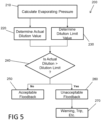
- the control module 22 may execute a floodback protection algorithm 200 ( Figure 5 ) to determine whether the floodback condition is at an acceptable (beneficial) level or an unacceptable (severe) level based on oil dilution values.
- the control module 22 may calculate evaporating pressure.
- the evaporating temperature can be assumed to be equal to the temperature measured by the third sensor 40 (suction temperature). Therefore, the evaporating pressure for a given working fluid can be calculated as a function of suction temperature (as evaporating temperature is proportional to suction temperature).
- the control module 22 may read a measured evaporating pressure value (e.g., measured by a temperature sensor or a pressure sensor) at step 210.
- the pressure P of the gaseous working fluid immediately above the oil level in the oil sump 34 can be assumed to be equal to evaporating pressure (calculated or measured at step 210).
- the constants a 1 through a 9 are dilution coefficients that are provided by working fluid (e.g., refrigerant) manufacturers for a combination of a given working fluid and a given oil. Exemplary dilution coefficients provided by DuPont TM for a combination of Suva ® R410A refrigerant and POE (polyolester) synthetic oil are shown in Figure 6 .
- the control module 22 may compare the actual dilution value (determined at step 220) and the dilution limit value (determined at step 230). If the actual dilution value is less than or equal to the dilution limit value, the control module 22 may determine that the floodback is at an acceptable level (step 250). If the actual dilution value is greater than the dilution limit value, the control module 22 may determine that the floodback is at an unacceptable level (step 260).
- control module 22 may, at step 270, issue a fault warning or notification, change a rotational speed of the motor 28 of the compressor 12, trip a motor protector temporarily disabling the compressor 12, and/or control the expansion device 16, the compressor motor 28, pumps (not shown), and/or blowers 15, 19, for example, to reduce or eliminate the floodback.
- the algorithm 200 may determine the severity of the floodback condition based on oil viscosity values.
- module may be replaced with the term “circuit” or “processing circuitry.”
- the term “module” may refer to, be part of, or include: an Application Specific Integrated Circuit (ASIC); a digital, analog, or mixed analog/digital discrete circuit; a digital, analog, or mixed analog/digital integrated circuit; a combinational logic circuit; a field programmable gate array (FPGA); a processor circuit (shared, dedicated, or group) that executes code; a memory circuit (shared, dedicated, or group) that stores code executed by the processor circuit; other suitable hardware components that provide the described functionality; or a combination of some or all of the above, such as in a system-on-chip.
- ASIC Application Specific Integrated Circuit
- FPGA field programmable gate array
- the module may include one or more interface circuits.
- the interface circuits may include wired or wireless interfaces that are connected to a local area network (LAN), the Internet, a wide area network (WAN), or combinations thereof.
- LAN local area network
- WAN wide area network
- the functionality of any given module of the present disclosure may be distributed among multiple modules that are connected via interface circuits. For example, multiple modules may allow load balancing.
- a server (also known as remote, or cloud) module may accomplish some functionality on behalf of a client module.
- code may include software, firmware, and/or microcode, and may refer to programs, routines, functions, classes, data structures, and/or objects.
- shared processor circuit encompasses a single processor circuit that executes some or all code from multiple modules.
- group processor circuit encompasses a processor circuit that, in combination with additional processor circuits, executes some or all code from one or more modules. References to multiple processor circuits encompass multiple processor circuits on discrete dies, multiple processor circuits on a single die, multiple cores of a single processor circuit, multiple threads of a single processor circuit, or a combination of the above.
- shared memory circuit encompasses a single memory circuit that stores some or all code from multiple modules.
- group memory circuit encompasses a memory circuit that, in combination with additional memories, stores some or all code from one or more modules.
- the term memory circuit is a subset of the term computer-readable medium.
- the term computer-readable medium does not encompass transitory electrical or electromagnetic signals propagating through a medium (such as on a carrier wave); the term computer-readable medium may therefore be considered tangible and non-transitory.
- Non-limiting examples of a non-transitory, tangible computer-readable medium are nonvolatile memory circuits (such as a flash memory circuit, an erasable programmable read-only memory circuit, or a mask read-only memory circuit), volatile memory circuits (such as a static random access memory circuit or a dynamic random access memory circuit), magnetic storage media (such as an analog or digital magnetic tape or a hard disk drive), and optical storage media (such as a CD, a DVD, or a Blu-ray Disc).
- nonvolatile memory circuits such as a flash memory circuit, an erasable programmable read-only memory circuit, or a mask read-only memory circuit
- volatile memory circuits such as a static random access memory circuit or a dynamic random access memory circuit
- magnetic storage media such as an analog or digital magnetic tape or a hard disk drive
- optical storage media such as a CD, a DVD, or a Blu-ray Disc
- the apparatuses and methods described in this application may be partially or fully implemented by a special purpose computer created by configuring a general purpose computer to execute one or more particular functions embodied in computer programs.
- the descriptions above serve as software specifications, which can be translated into the computer programs by the routine work of a skilled technician or programmer.
- the computer programs include processor-executable instructions that are stored on at least one non-transitory, tangible computer-readable medium.
- the computer programs may also include or rely on stored data.
- the computer programs may encompass a basic input/output system (BIOS) that interacts with hardware of the special purpose computer, device drivers that interact with particular devices of the special purpose computer, one or more operating systems, user applications, background services, background applications, etc.
- BIOS basic input/output system
- the computer programs may include: (i) descriptive text to be parsed, such as HTML (hypertext markup language) or XML (extensible markup language), (ii) assembly code, (iii) object code generated from source code by a compiler, (iv) source code for execution by an interpreter, (v) source code for compilation and execution by a just-in-time compiler, etc.
- source code may be written using syntax from languages including C, C++, C#, Objective C, Haskell, Go, SQL, R, Lisp, Java ® , Fortran, Perl, Pascal, Curl, OCaml, Javascript ® , HTML5, Ada, ASP (active server pages), PHP, Scala, Eiffel, Smalltalk, Erlang, Ruby, Flash@, Visual Basic ® , Lua, and Python ® .
Landscapes
- Engineering & Computer Science (AREA)
- Mechanical Engineering (AREA)
- General Engineering & Computer Science (AREA)
- Physics & Mathematics (AREA)
- Thermal Sciences (AREA)
- Applications Or Details Of Rotary Compressors (AREA)
- Control Of Positive-Displacement Pumps (AREA)
- Air Conditioning Control Device (AREA)
Description
- The present disclosure relates to a compressor floodback protection system.
- This section provides background information related to the present disclosure and is not necessarily prior art.
- A climate-control system such as, for example, a heat-pump system, a refrigeration system, or an air conditioning system, may include a fluid circuit having an outdoor heat exchanger, one or more indoor heat exchangers, one or more expansion devices disposed between the indoor and outdoor heat exchangers, and one or more compressors circulating a working fluid (e.g., refrigerant or carbon dioxide) between the indoor and outdoor heat exchangers. Efficient and reliable operation of the one or more compressors is desirable to ensure that the climate-control system in which the one or more compressors are installed is capable of effectively and efficiently providing a cooling and/or heating effect on demand.
WO 2009/038624 A1 discloses a system and method for determining a subcooling associated with a refrigerant charge level.EP 2952829 A1 discloses a refrigeration-cycle device and control method.JP H07180933A US 2003/077179 A1 discloses an apparatus for monitoring a compressor. - This section provides a general summary of the disclosure, and is not a comprehensive disclosure of its full scope or all of its features. The scope of the invention is defined by the appended claims.
- In one form, the present disclosure provides a climate-control system that includes a compressor, a condenser, an evaporator, a first sensor, a second sensor, a third sensor, and a control module. The compressor includes a motor and a compression mechanism. The condenser receives compressed working fluid from the compressor. The evaporator is in fluid communication with the compressor and disposed downstream of the condenser and upstream of the compressor. The first sensor detects an electrical operating parameter of the motor. The second sensor detects a discharge temperature of working fluid discharged by the compression mechanism. The third sensor detects a suction temperature of working fluid between the evaporator and the compression mechanism. The control module is in communication with the first, second and third sensors and determines whether a refrigerant floodback condition is occurring in the compressor based on data received from the first, second and third sensors.
- In some configurations, the control module determines whether the refrigerant floodback condition is occurring based on a comparison between a calculated discharge-superheat-value and a predetermined discharge-superheat-threshold.
- In some configurations, a severity of the refrigerant floodback condition is determined based on a level of oil dilution in an oil sump of the compressor.
- In some configurations, the control module issues a fault warning or a fault trip in response to determining the severity of the refrigerant floodback condition.
- In some configurations, the pressure (P) of gas immediately above the oil level is measured by the third sensor.
- In another form, the present disclosure provides a system that includes a compressor, a first heat exchanger, a second heat exchanger, a first sensor, a second sensor, a third sensor, and processing circuitry. The system may further comprise a fourth sensor. The compressor includes a shell, a compression mechanism disposed within the shell, and a motor driving the compression mechanism. The first heat exchanger receives compressed working fluid from the compressor. The second heat exchanger is in fluid communication with the compressor and the first heat exchanger and may provide suction-pressure working fluid to the compressor. The first sensor detects an electrical operating parameter (e.g., electrical current of the motor) indicative of a temperature of working fluid within the first heat exchanger (e.g., a saturated temperature or a condensing temperature). The second sensor detects a discharge temperature of fluid discharged from the compressor. The third sensor detects a suction temperature of fluid upstream of the compression mechanism and downstream of the first and second heat exchangers. The fourth sensor may detect an oil temperature of oil in a sump defined by the shell. The processing circuitry is in communication with the first, second, third and fourth sensors. The processing circuitry determines whether a refrigerant floodback condition is occurring in the compression mechanism and a severity of the refrigerant floodback condition based on data received from the first, second, third and optionally fourth sensors.
- In some configurations, the first sensor is a current sensor that measures a current of the motor.
- In some configurations, the only measured data used to detect the refrigerant floodback condition is data measured by the first, second and third sensors.
- In some configurations, the processing circuitry determines whether a refrigerant floodback condition has occurred based on a comparison between a calculated discharge-superheat-value and a predetermined discharge-superheat-threshold.
- In some configurations, the severity of the refrigerant floodback condition is determined based on a level of oil dilution in an oil sump disposed within the shell of the compressor.
- In some configurations, the level of oil dilution is calculated using the equation:

- In some configurations, the severity of the refrigerant floodback condition is determined based on a comparison of the level of oil dilution and a dilution limit value.
- In some configurations, the dilution limit value is determined based on a calculated condensing temperature and a calculated evaporating temperature.
- In some configurations, the pressure (P) of gas immediately above the oil level is determined based on the suction temperature measured by the third sensor.
- In some configurations, the processing circuitry issues a fault warning or a fault trip in response to determining the severity of the refrigerant floodback condition.
- In some configurations, the compressor is a low-side scroll compressor.
- Further areas of applicability will become apparent from the description provided herein. The description and specific examples in this summary are intended for purposes of illustration only and are not intended to limit the scope of the present disclosure.
- The drawings described herein are for illustrative purposes only of selected embodiments and not all possible implementations, and are not intended to limit the scope of the present disclosure.
-
Figure 1 is a schematic representation of an exemplary climate-control system according to the principles of the present disclosure; -
Figure 2 is a flowchart depicting an algorithm for detecting a floodback condition; -
Figure 3 is a graph illustrating a relationship among compressor power, evaporating temperature and condensing temperature; -
Figure 4 is a table of predicted discharge superheat values; -
Figure 5 is a flowchart depicting an algorithm for determining a severity of the floodback condition; -
Figure 6 is a table of exemplary dilution coefficient values; -
Figure 7 is a graph of dilution limit versus pressure ratio; and -
Figure 8 is a graph of condensing temperature versus motor current. - Corresponding reference numerals indicate corresponding parts throughout the several views of the drawings.
- Example embodiments will now be described more fully with reference to the accompanying drawings.
- Example embodiments are provided so that this disclosure will be thorough, and will fully convey the scope to those who are skilled in the art. Numerous specific details are set forth such as examples of specific components, devices, and methods, to provide a thorough understanding of embodiments of the present disclosure. It will be apparent to those skilled in the art that specific details need not be employed, that example embodiments may be embodied in many different forms and that neither should be construed to limit the scope of the disclosure. In some example embodiments, well-known processes, well-known device structures, and well-known technologies are not described in detail.
- The terminology used herein is for the purpose of describing particular example embodiments only and is not intended to be limiting. As used herein, the singular forms "a," "an," and "the" may be intended to include the plural forms as well, unless the context clearly indicates otherwise. The terms "comprises," "comprising," "including," and "having," are inclusive and therefore specify the presence of stated features, integers, steps, operations, elements, and/or components, but do not preclude the presence or addition of one or more other features, integers, steps, operations, elements, components, and/or groups thereof. The method steps, processes, and operations described herein are not to be construed as necessarily requiring their performance in the particular order discussed or illustrated, unless specifically identified as an order of performance. It is also to be understood that additional or alternative steps may be employed.
- When an element or layer is referred to as being "on," "engaged to," "connected to," or "coupled to" another element or layer, it may be directly on, engaged, connected or coupled to the other element or layer, or intervening elements or layers may be present. In contrast, when an element is referred to as being "directly on," "directly engaged to," "directly connected to," or "directly coupled to" another element or layer, there may be no intervening elements or layers present. Other words used to describe the relationship between elements should be interpreted in a like fashion (e.g., "between" versus "directly between," "adjacent" versus "directly adjacent," etc.). As used herein, the term "and/or" includes any and all combinations of one or more of the associated listed items.
- Although the terms first, second, third, etc. may be used herein to describe various elements, components, regions, layers and/or sections, these elements, components, regions, layers and/or sections should not be limited by these terms. These terms may be only used to distinguish one element, component, region, layer or section from another region, layer or section. Terms such as "first," "second," and other numerical terms when used herein do not imply a sequence or order unless clearly indicated by the context. Thus, a first element, component, region, layer or section discussed below could be termed a second element, component, region, layer or section without departing from the teachings of the example embodiments.
- Spatially relative terms, such as "inner," "outer," "beneath," "below," "lower," "above," "upper," and the like, may be used herein for ease of description to describe one element or feature's relationship to another element(s) or feature(s) as illustrated in the figures. Spatially relative terms may be intended to encompass different orientations of the device in use or operation in addition to the orientation depicted in the figures. For example, if the device in the figures is turned over, elements described as "below" or "beneath" other elements or features would then be oriented "above" the other elements or features. Thus, the example term "below" can encompass both an orientation of above and below. The device may be otherwise oriented (rotated 90 degrees or at other orientations) and the spatially relative descriptors used herein interpreted accordingly.
- With reference to
Figure 1 , a climate-control system 10 is provided that may include one ormore compressors 12, anoutdoor heat exchanger 14, anoutdoor blower 15, an expansion device 16 (e.g., an expansion valve, capillary tube, etc.), anindoor heat exchanger 18, and anindoor blower 19. Thecompressor 12 compresses working fluid (e.g., refrigerant, carbon dioxide, etc.) and circulates the working fluid throughout thesystem 10. In some configurations, the climate-control system 10 may be a heat-pump system having a reversing valve (not shown) operable to control a direction of working fluid flow through thesystem 10 to switch thesystem 10 between a heating mode and a cooling mode. In some configurations, the climate-control system 10 may be a chiller system, an airconditioning system or a refrigeration system, for example, and may be operable in only the cooling mode. As will be described in more detail below, a control module 22 may include processing circuitry that determines whether a floodback condition is occurring in thecompressor 12 and a severity level of the floodback condition. In some configurations, the control module 22 may also control operation of one or more of thecompressor 12, theoutdoor blower 15, theexpansion device 16 and theindoor blower 19. - The
compressor 12 may include ashell 24, acompression mechanism 26 and amotor 28. Thecompression mechanism 26 is disposed within theshell 24 and is driven by themotor 28 via a crankshaft (not shown). In the particular configuration shown inFigure 1 , thecompressor 12 is a low-side scroll compressor. That is, thecompression mechanism 26 is a scroll compression mechanism disposed within a suction-pressure region 30 of theshell 24. Thecompression mechanism 26 draws suction-pressure working fluid from the suction-pressure region 30 and may discharge compressed working fluid into a discharge-pressure region 32 of theshell 24. Themotor 28 may also be disposed within the suction-pressure region 30. A lower end of the suction-pressure region 30 of theshell 24 may define anoil sump 34 containing a volume of oil for lubrication and cooling of thecompression mechanism 26, themotor 28 and other moving parts of thecompressor 12. - While the
compressor 12 is described above as a low-side compressor, in some configurations, thecompressor 12 could be a high-side compressor (i.e., thecompression mechanism 26,motor 28 andoil sump 34 could be disposed in a discharge-pressure region of the shell). Furthermore, in some configurations, thecompressor 12 could be a reciprocating compressor or a rotary vane compressor, for example, rather than a scroll compressor. - In a cooling mode, the
outdoor heat exchanger 14 may operate as a condenser or as a gas cooler and may cool discharge-pressure working fluid received from thecompressor 12 by transferring heat from the working fluid to air forced over theoutdoor heat exchanger 14 by theoutdoor blower 15, for example. Theoutdoor blower 15 could include a fixed-speed, multi-speed or variable-speed fan. In the cooling mode, theindoor heat exchanger 18 may operate as an evaporator in which the working fluid absorbs heat from air forced over theindoor heat exchanger 18 by theindoor blower 19. In a heating mode (in configurations where thesystem 10 is a heat pump), theoutdoor heat exchanger 14 may operate as an evaporator, and theindoor heat exchanger 18 may operate as a condenser or as a gas cooler and may transfer heat from working fluid discharged from thecompressor 12 to air forced over theindoor heat exchanger 18 by theindoor blower 19. - The control module 22 may be in communication with first, second, third and
fourth sensors first sensor 36 may be a current sensor disposed within theshell 24 that measures a current draw of themotor 28. Thesecond sensor 38 may be a temperature sensor and may measure a discharge temperature of working fluid discharged from thecompressor 12. In some configurations, thesecond sensor 38 may be mounted on adischarge line 42 that fluidly connects thecompressor 12 and theoutdoor heat exchanger 14. In some configurations, thesecond sensor 38 could be mounted within the compressor 12 (e.g., in the discharge-pressure region 32 or at the discharge passage of the compression mechanism 26). Thethird sensor 40 may be a temperature sensor and may measure a suction temperature of working fluid provided to thecompressor 12. In some configurations, thethird sensor 40 may be mounted on asuction line 44 that fluidly connects thecompressor 12 and theindoor heat exchanger 18. In some configurations, thethird sensor 40 may be mounted within the compressor 12 (e.g., in the suction-pressure region 30) or on a suction fitting connecting thesuction line 44 with the shell of thecompressor 12. Thefourth sensor 41 may be a temperature sensor disposed within theoil sump 34 and may measure a temperature of oil in theoil sump 34. Thesensors sensors - As described above, the control module 22 determines whether a floodback condition is occurring in the
compressor 12 and a severity level of the floodback condition. The control module 22 may determine whether the floodback condition is occurring using measured data only from the first, second andthird sensors - A floodback condition is a condition where liquid working fluid flows into the
suction line 44 from theevaporator 18. During a floodback condition, the working fluid in thesuction line 44 may not be completely evaporated and may be at least partially in liquid phase (i.e., a mixture of gaseous and liquid working fluid or entirely liquid working fluid). Severe liquid floodback can be detrimental to the reliability of thecompressor 12 and can unacceptably increase oil dilution and reduce oil viscosity and oil-film thicknesses between mating moving parts, which can damage the moving parts. Floodback conditions can be caused by blocked evaporator fans, stuck or malfunctioning expansion valves, and defrost cycles, for example. - While severe floodback can be detrimental to compressor health, lower levels of floodback can be beneficial. For example, acceptable levels of floodback can lower discharge temperatures and increase oil-film thicknesses during certain operating conditions of the system 10 (e.g., operating conditions where evaporating temperatures are low and condensing temperatures are high). Beneficial levels of floodback can expand the operating envelope of the compressor and reduce or eliminate the need for liquid-injection or vapor-injection systems in certain applications.
- With reference to
Figure 2 , a floodback-detection algorithm 100 will be described. Atstep 110, the control module 22 determines a non-measured condensing temperature value of thesystem 10. The control module 22 can determine the condensing temperature based on data received from only thefirst sensor 36.Figure 3 includes a graph showing compressor power as a function of evaporating temperature (Tevap) and condensing temperature (Tcond). As shown, power remains fairly constant irrespective of evaporating temperature. Therefore, while an exact evaporating temperature can be determined by a second degree polynomial (i.e., a quadratic function), for purposes of detecting floodback, the evaporating temperature can be determined by a fist degree polynomial (i.e., linear function) and can be approximated as roughly 45 degrees F, for example, in a cooling mode. In other words, the error associated with choosing an incorrect evaporating temperature is minimal when determining condensing temperature. - The graph of
Figure 3 includes compressor power on the Y-axis and condensing temperature on the X-axis. Compressor power P can be determined using the equation P = V * I, where I is the measured compressor current obtained by thefirst sensor 36 and V is a known voltage for a given compressor. Compressor power P can also be determined using the equation P = I2R, wherein R is a known resistance of themotor 28. - The condensing temperature is calculated for the individual compressor and is therefore specific to compressor model and size. The following equation is used in determining condensing temperature, where P is compressor power, C0-C9 are compressor-specific constants, Tcond is condensing temperature, and Tevap is evaporating temperature:

- The above equation is applicable to all compressors, with constants C0-C9 being compressor model and size specific, as published by compressor manufacturers, and can be simplified as necessary by reducing the equation to a second-order polynomial with minimal compromise on accuracy. The equations and constants can be loaded into the control module 22 by the manufacturer, in the field during installation using a hand-held service tool, or downloaded directly to the control module 22 from the internet, for example.
- The condensing temperature, at a specific compressor power (based on measured current draw by the first sensor 36), is determined by referencing a plot of evaporating temperature (using the equation above, for example) for a given system versus compressor power consumption. The condensing temperature can be read by cross-referencing power consumption (determined from a measured current reading) against the evaporating temperature plot. Therefore, the condensing temperature is simply a function of reading a current drawn at the
first sensor 36. For example,FIG. 3 shows an exemplary power consumption of 3400 watts (as determined by the current draw read by the first sensor 36). The control module 22 is able to determine the condensing temperature by simply cross-referencing power consumption of 3400 watts for a given evaporating temperature (i.e., 45 degrees F, 50 degrees F, 55 degrees F, as shown) to determine the corresponding condensing temperature. It should be noted that the evaporating temperature can be approximated as being either 45 degrees F, 50 degrees F, or 55 degrees F without materially affecting the condensing temperature calculation. Therefore, 45 degrees F is typically chosen by the control module 22 when making the above calculation. - As an alternative to the above methods for determining condensing temperature, the condensing temperature may be calculated using only motor current data (e.g., from the first sensor 36). That is, the condensing temperature may be calculated from a polynomial equation based on a regression of current (amperage) versus condensing temperature data (e.g., data published by a compressor manufacturer), where the motor current correlates closely to condensing pressure (and therefore, condensing temperature), as shown in
Figure 8 . The following equation is an example of such a polynomial equation for an exemplary compressor, where A is compressor-motor current, C0-C5 are compressor-specific constants (e.g., constants that are specific to a particular model and size compressor and obtained through testing for a particular compressor), and Tcond is condensing temperature:
- The above equation is applicable to all compressors (with constants C0-C5 being chosen for a specific compressor) and can be simplified as necessary by reducing the equation to a lesser-order polynomial with minimal comprise on accuracy. Multiple equations can be generated as necessary to account for additional variables (such as voltage or operating speed) on the behavior of condensing pressure on current. Because the principles of the present disclosure can be used with multi-speed compressors and applied in multiple grid voltage situations, the above equation may be corrected based on a motor speed (e.g., obtained from current signal) and a measured voltage, for example.
- While
step 110 of the floodback-detection algorithm 100 is described above as determining a non-measured condensing temperature, in some configurations of thealgorithm 100, the control module 22 may, atstep 110, obtain a measured condensing temperature value from a temperature sensor that measures condensing temperature directly. In such configurations, thefirst sensor 36 may be a temperature sensor disposed on or in a coil of theoutdoor heat exchanger 14, for example. Thefirst sensor 36 may measure the condensing temperature and communicate the measured condensing temperature value to the control module 22 via a wired or wireless connection between thefirst sensor 36 and the control module 22. Alternatively, thefirst sensor 36 may be a pressure sensor measuring the pressure of working fluid at a high-pressure side of the system 10 (e.g., at a location at or near theoutdoor heat exchanger 14 or along thedischarge line 42, for example. The control module 22 may receive this pressure data from thefirst sensor 36 and convert the measured pressure value to a condensing temperature value (i.e., since the pressure of the working fluid at a location within thesystem 10 is proportional to the temperature of the working fluid at the same location). - Referring again to
Figure 2 , once the condensing temperature has been determined, the control module 22 may determine a theoretical discharge-superheat-value (DSHtheor) atstep 120 and an actual discharge-superheat-value (DSHactual) atstep 130. To determine the theoretical discharge-superheat-value, the control module 22 may reference a lookup table or map, such as the table shown inFigure 4 . The lookup table shown inFigure 4 includes theoretical discharge-superheat-values corresponding to a particular set of condensing temperature and suction temperature values. The control module 22 may use the condensing temperature value determined atstep 110 and a suction temperature value measured by thethird sensor 40 to lookup the theoretical discharge-superheat-value that corresponds to those values in the lookup table. - The control module 22 may calculate the actual discharge-superheat-value (step 130) by subtracting the condensing temperature (determined at step 110) from the temperature measurement taken by the second sensor 38 (i.e., discharge temperature; hereinafter, Tdis). Stated in the form of an equation, DSHactual = Tdis - Tcond.
- After
steps step 140, compare the actual discharge-superheat-value (calculated at step 130) with the theoretical discharge-superheat-value (determined at step 120). If the actual discharge-superheat-value is greater than or equal to the theoretical discharge-superheat-value, then the control module 22 determines that a floodback condition does not exist and the working fluid in thedischarge line 42 is superheated (step 150). If the actual discharge-superheat-value is less than the theoretical discharge-superheat-value, then the control module 22 determines that a floodback condition does exist (step 160). - If the control module 22 determines that a floodback condition exists, the control module 22 may execute a floodback protection algorithm 200 (
Figure 5 ) to determine whether the floodback condition is at an acceptable (beneficial) level or an unacceptable (severe) level based on oil dilution values. Atstep 210, the control module 22 may calculate evaporating pressure. During a floodback condition, the evaporating temperature can be assumed to be equal to the temperature measured by the third sensor 40 (suction temperature). Therefore, the evaporating pressure for a given working fluid can be calculated as a function of suction temperature (as evaporating temperature is proportional to suction temperature). In some configurations, the control module 22 may read a measured evaporating pressure value (e.g., measured by a temperature sensor or a pressure sensor) atstep 210. - At
step 220, the control module 22 may calculate an actual oil dilution value using the following equation:
oil sump 34 within thecompressor 12, ω is the actual oil dilution value, T is a temperature of the oil in the oil sump 34 (measured by the fourth sensor 41), and a 1 through a 9 are constants. In a low-side compressor, the pressure P of the gaseous working fluid immediately above the oil level in theoil sump 34 can be assumed to be equal to evaporating pressure (calculated or measured at step 210). The constants a 1 through a 9 are dilution coefficients that are provided by working fluid (e.g., refrigerant) manufacturers for a combination of a given working fluid and a given oil. Exemplary dilution coefficients provided by DuPont™ for a combination of Suva® R410A refrigerant and POE (polyolester) synthetic oil are shown inFigure 6 . - At
step 230, the control module 22 may determine a dilution limit value based on a pressure ratio (condensing pressure to evaporating pressure) of thesystem 10. Because a one-to-one correlation exists between condensing pressure and condensing temperature and between evaporating pressure and evaporating temperature, the pressure ratio (Pratio) of thesystem 10 can be calculated by the equation Pratio = Tcond /Tevap. As described above, the condensing temperature is calculated atstep 110 of thefloodback detection algorithm 100, and evaporating temperature can be assumed to be equal to the suction temperature measured by thethird sensor 40. Once the pressure ratio is determined, the control module 22 can determine the dilution limit value by a lookup table or from the graph and equation shown inFigure 7 , where y is the dilution limit value, and x is the pressure ratio. - At
step 240, the control module 22 may compare the actual dilution value (determined at step 220) and the dilution limit value (determined at step 230). If the actual dilution value is less than or equal to the dilution limit value, the control module 22 may determine that the floodback is at an acceptable level (step 250). If the actual dilution value is greater than the dilution limit value, the control module 22 may determine that the floodback is at an unacceptable level (step 260). If the floodback is at an unacceptable level, the control module 22 may, atstep 270, issue a fault warning or notification, change a rotational speed of themotor 28 of thecompressor 12, trip a motor protector temporarily disabling thecompressor 12, and/or control theexpansion device 16, thecompressor motor 28, pumps (not shown), and/orblowers - While the
algorithm 200 is described above as determining whether the floodback condition is at an acceptable level or an unacceptable level based on oil dilution values, in some configurations, thealgorithm 200 may determine the severity of the floodback condition based on oil viscosity values. - In this application, including the definitions below, the term "module" may be replaced with the term "circuit" or "processing circuitry." The term "module" may refer to, be part of, or include: an Application Specific Integrated Circuit (ASIC); a digital, analog, or mixed analog/digital discrete circuit; a digital, analog, or mixed analog/digital integrated circuit; a combinational logic circuit; a field programmable gate array (FPGA); a processor circuit (shared, dedicated, or group) that executes code; a memory circuit (shared, dedicated, or group) that stores code executed by the processor circuit; other suitable hardware components that provide the described functionality; or a combination of some or all of the above, such as in a system-on-chip.
- The module may include one or more interface circuits. In some examples, the interface circuits may include wired or wireless interfaces that are connected to a local area network (LAN), the Internet, a wide area network (WAN), or combinations thereof. The functionality of any given module of the present disclosure may be distributed among multiple modules that are connected via interface circuits. For example, multiple modules may allow load balancing. In a further example, a server (also known as remote, or cloud) module may accomplish some functionality on behalf of a client module.
- The term code, as used above, may include software, firmware, and/or microcode, and may refer to programs, routines, functions, classes, data structures, and/or objects. The term shared processor circuit encompasses a single processor circuit that executes some or all code from multiple modules. The term group processor circuit encompasses a processor circuit that, in combination with additional processor circuits, executes some or all code from one or more modules. References to multiple processor circuits encompass multiple processor circuits on discrete dies, multiple processor circuits on a single die, multiple cores of a single processor circuit, multiple threads of a single processor circuit, or a combination of the above. The term shared memory circuit encompasses a single memory circuit that stores some or all code from multiple modules. The term group memory circuit encompasses a memory circuit that, in combination with additional memories, stores some or all code from one or more modules.
- The term memory circuit is a subset of the term computer-readable medium. The term computer-readable medium, as used herein, does not encompass transitory electrical or electromagnetic signals propagating through a medium (such as on a carrier wave); the term computer-readable medium may therefore be considered tangible and non-transitory. Non-limiting examples of a non-transitory, tangible computer-readable medium are nonvolatile memory circuits (such as a flash memory circuit, an erasable programmable read-only memory circuit, or a mask read-only memory circuit), volatile memory circuits (such as a static random access memory circuit or a dynamic random access memory circuit), magnetic storage media (such as an analog or digital magnetic tape or a hard disk drive), and optical storage media (such as a CD, a DVD, or a Blu-ray Disc).
- The apparatuses and methods described in this application may be partially or fully implemented by a special purpose computer created by configuring a general purpose computer to execute one or more particular functions embodied in computer programs. The descriptions above serve as software specifications, which can be translated into the computer programs by the routine work of a skilled technician or programmer.
- The computer programs include processor-executable instructions that are stored on at least one non-transitory, tangible computer-readable medium. The computer programs may also include or rely on stored data. The computer programs may encompass a basic input/output system (BIOS) that interacts with hardware of the special purpose computer, device drivers that interact with particular devices of the special purpose computer, one or more operating systems, user applications, background services, background applications, etc.
- The computer programs may include: (i) descriptive text to be parsed, such as HTML (hypertext markup language) or XML (extensible markup language), (ii) assembly code, (iii) object code generated from source code by a compiler, (iv) source code for execution by an interpreter, (v) source code for compilation and execution by a just-in-time compiler, etc. As examples only, source code may be written using syntax from languages including C, C++, C#, Objective C, Haskell, Go, SQL, R, Lisp, Java®, Fortran, Perl, Pascal, Curl, OCaml, Javascript®, HTML5, Ada, ASP (active server pages), PHP, Scala, Eiffel, Smalltalk, Erlang, Ruby, Flash@, Visual Basic®, Lua, and Python®.
- None of the elements recited in the claims are intended to be a means-plus-function element unless an element is expressly recited using the phrase "means for," or in the case of a method claim using the phrases "operation for" or "step for."
- The foregoing description of the embodiments has been provided for purposes of illustration and description. It is not intended to be exhaustive or to limit the disclosure. Individual elements or features of a particular embodiment are generally not limited to that particular embodiment, but, where applicable, are interchangeable and can be used in a selected embodiment, even if not specifically shown or described. The same may also be varied in many ways. Such variations are not to be regarded as a departure from the disclosure, and all such modifications are intended to be included within the scope of the disclosure.
Claims (13)
- A system (10) comprising:a compressor (12) having a shell (24), a compression mechanism (26) disposed within the shell, and a motor (28) configured to drive the compression mechanism;a first heat exchanger (14) configured to receive compressed working fluid from the compressor;a second heat exchanger (18) in fluid communication with the compressor and the first heat exchanger;a first sensor (36) configured to detect an electrical operating parameter of the motor;a second sensor (38) configured to detect a discharge temperature of working fluid discharged from the compressor;a third sensor (40) configured to detect a suction temperature of working fluid upstream of the compression mechanism and downstream of the first and second heat exchangers; andcharacterized by:processing circuitry (22) in communication with the first, second, and third sensors and configured to determine whether a refrigerant floodback condition is occurring based on data received from the first, second, and third sensors,wherein the refrigerant floodback condition is a condition where liquid working fluid flows into a suction line (44) from the second heat exchanger.
- The system (10) of claim 1, wherein the first sensor (36) is a current sensor configured to measure a current of the motor (28).
- The system (10) of claim 1, wherein the only measured data used to detect the refrigerant floodback condition is data measured by the first, second and third sensors (36, 38, 40).
- The system (10) of any preceding claim, wherein the processing circuitry (22) is configured to determine whether a refrigerant floodback condition has occurred based on a comparison between a calculated discharge-superheat-value and a predetermined discharge-superheat-threshold.
- The system (10) of any one of the preceding claims, further comprising a fourth sensor (41) configured to detect an oil temperature of oil in an oil sump (34) defined by the shell (34), wherein the processing circuitry (22) is in communication with the fourth sensor (41), and wherein the processing circuitry (22) is configured to determine a severity of the refrigerant floodback condition based on data from the fourth sensor (41).
- The system (10) of claim 5, wherein the severity of the refrigerant floodback condition is determined based on a level of oil dilution in the oil sump (34) disposed within the shell (24) of the compressor (12).
- The system (10) of claim 6, wherein the level of oil dilution is calculated using the equation:

- The system (10) of claim 7, wherein the severity of the refrigerant floodback condition is determined based on a comparison of the level of oil dilution and a dilution limit value.
- The system (10) of claim 8, wherein the dilution limit value is determined based on a calculated condensing temperature and a calculated evaporating temperature.
- The system (10) of claim 9, wherein the pressure (P) of gas immediately above the oil level is determined based on the suction temperature measured by the third sensor (40).
- The system (10) of claim 10, wherein the processing circuitry (22) is configured to issue a fault warning or a fault trip in response to determining the severity of the refrigerant floodback condition.
- The system (10) of claim 11, wherein the compressor (12) is a low-side scroll compressor.
- The system of any preceding claim, wherein the processing circuitry (22) is configured to determine a condensing temperature based on data received from only the first sensor (36).
Applications Claiming Priority (3)
| Application Number | Priority Date | Filing Date | Title |
|---|---|---|---|
| US201662296841P | 2016-02-18 | 2016-02-18 | |
| US15/428,410 US10801762B2 (en) | 2016-02-18 | 2017-02-09 | Compressor floodback protection system |
| PCT/US2017/018484 WO2017143267A1 (en) | 2016-02-18 | 2017-02-17 | Compressor floodback protection system |
Publications (3)
| Publication Number | Publication Date |
|---|---|
| EP3417219A1 EP3417219A1 (en) | 2018-12-26 |
| EP3417219A4 EP3417219A4 (en) | 2019-11-06 |
| EP3417219B1 true EP3417219B1 (en) | 2024-03-27 |
Family
ID=59625536
Family Applications (1)
| Application Number | Title | Priority Date | Filing Date |
|---|---|---|---|
| EP17753978.0A Active EP3417219B1 (en) | 2016-02-18 | 2017-02-17 | Compressor floodback protection system |
Country Status (4)
| Country | Link |
|---|---|
| US (2) | US10801762B2 (en) |
| EP (1) | EP3417219B1 (en) |
| CN (1) | CN108885040B (en) |
| WO (1) | WO2017143267A1 (en) |
Families Citing this family (7)
| Publication number | Priority date | Publication date | Assignee | Title |
|---|---|---|---|---|
| US11125482B2 (en) * | 2019-05-31 | 2021-09-21 | Trane International Inc. | Lubricant quality management for a compressor |
| KR102693095B1 (en) * | 2019-09-20 | 2024-08-09 | 두원중공업(주) | Diagnosis method of abnormality of electric motor compressor |
| DE102020118854B4 (en) * | 2020-07-16 | 2022-12-29 | SPH Sustainable Process Heat GmbH | Temperature management system, heat pump and method for controlling a lubricant temperature |
| US11808468B2 (en) * | 2021-08-31 | 2023-11-07 | Schneider Electric USA, Inc. | Continuous learning compressor input power predictor |
| IT202200024204A1 (en) * | 2022-11-24 | 2024-05-24 | Ferroli Spa | ENERGY MONITORING SYSTEM FOR A HEAT PUMP. |
| CN118999031B (en) * | 2024-10-23 | 2025-03-21 | 浙江蔚盛空调压缩机有限公司 | An electric scroll compressor regulating control system |
| CN121576276A (en) * | 2025-12-09 | 2026-02-27 | 冰山松洋压缩机(大连)有限公司 | A system for monitoring the state of refrigerant oil in the oil sump during compressor operation. |
Citations (1)
| Publication number | Priority date | Publication date | Assignee | Title |
|---|---|---|---|---|
| US20030077179A1 (en) * | 2001-10-19 | 2003-04-24 | Michael Collins | Compressor protection module and system and method incorporating same |
Family Cites Families (39)
| Publication number | Priority date | Publication date | Assignee | Title |
|---|---|---|---|---|
| US4918931A (en) * | 1989-09-05 | 1990-04-24 | Mydax Corporation | Compressor slugging prevention method for a refrigeration system |
| JPH07180933A (en) | 1993-12-21 | 1995-07-18 | Mitsubishi Electric Corp | Refrigeration cycle equipment |
| DE19506143C2 (en) | 1995-02-22 | 1998-01-15 | Danfoss As | Method for controlling the superheating temperature of the refrigerant in an evaporator device of a refrigeration or heat pump system and device for carrying out the method |
| US6578373B1 (en) * | 2000-09-21 | 2003-06-17 | William J. Barbier | Rate of change detector for refrigerant floodback |
| US6675591B2 (en) * | 2001-05-03 | 2004-01-13 | Emerson Retail Services Inc. | Method of managing a refrigeration system |
| US6658373B2 (en) | 2001-05-11 | 2003-12-02 | Field Diagnostic Services, Inc. | Apparatus and method for detecting faults and providing diagnostics in vapor compression cycle equipment |
| US6886354B2 (en) * | 2003-04-04 | 2005-05-03 | Carrier Corporation | Compressor protection from liquid hazards |
| US7412842B2 (en) | 2004-04-27 | 2008-08-19 | Emerson Climate Technologies, Inc. | Compressor diagnostic and protection system |
| US7275377B2 (en) | 2004-08-11 | 2007-10-02 | Lawrence Kates | Method and apparatus for monitoring refrigerant-cycle systems |
| WO2006023075A2 (en) | 2004-08-11 | 2006-03-02 | Lawrence Kates | Method and apparatus for monitoring refrigerant-cycle systems |
| US7234313B2 (en) | 2004-11-02 | 2007-06-26 | Stargate International, Inc. | HVAC monitor and superheat calculator system |
| US7665315B2 (en) * | 2005-10-21 | 2010-02-23 | Emerson Retail Services, Inc. | Proofing a refrigeration system operating state |
| US20070089436A1 (en) | 2005-10-21 | 2007-04-26 | Abtar Singh | Monitoring refrigerant in a refrigeration system |
| EP2032914B1 (en) | 2006-05-26 | 2018-09-26 | Carrier Corporation | Superheat control for hvac&r systems |
| US8590325B2 (en) | 2006-07-19 | 2013-11-26 | Emerson Climate Technologies, Inc. | Protection and diagnostic module for a refrigeration system |
| CN101311851B (en) | 2007-05-25 | 2013-05-22 | 开利公司 | Modified fuzzy control for cooler electronic expansion valve |
| US7775057B2 (en) | 2007-06-15 | 2010-08-17 | Trane International Inc. | Operational limit to avoid liquid refrigerant carryover |
| WO2009038624A1 (en) | 2007-09-19 | 2009-03-26 | Emerson Climate Technologies, Inc. | Refrigeration monitoring system and method |
| US8418483B2 (en) * | 2007-10-08 | 2013-04-16 | Emerson Climate Technologies, Inc. | System and method for calculating parameters for a refrigeration system with a variable speed compressor |
| US8459053B2 (en) | 2007-10-08 | 2013-06-11 | Emerson Climate Technologies, Inc. | Variable speed compressor protection system and method |
| US9541907B2 (en) | 2007-10-08 | 2017-01-10 | Emerson Climate Technologies, Inc. | System and method for calibrating parameters for a refrigeration system with a variable speed compressor |
| WO2009048466A1 (en) | 2007-10-10 | 2009-04-16 | Carrier Corporation | Suction superheat control based on refrigerant condition at discharge |
| JP5045524B2 (en) | 2008-03-31 | 2012-10-10 | ダイキン工業株式会社 | Refrigeration equipment |
| KR101552618B1 (en) | 2009-02-25 | 2015-09-11 | 엘지전자 주식회사 | Air conditioner |
| JP4770976B2 (en) | 2009-11-25 | 2011-09-14 | ダイキン工業株式会社 | Container refrigeration equipment |
| JP4854779B2 (en) | 2009-12-09 | 2012-01-18 | シャープ株式会社 | Air conditioner, expansion valve opening control method and program |
| US10107536B2 (en) | 2009-12-18 | 2018-10-23 | Carrier Corporation | Transport refrigeration system and methods for same to address dynamic conditions |
| US8590328B2 (en) | 2010-02-03 | 2013-11-26 | Hill Phoenix, Inc. | Refrigeration system with multi-function heat exchanger |
| JP5058324B2 (en) | 2010-10-14 | 2012-10-24 | 三菱電機株式会社 | Refrigeration cycle equipment |
| US8924181B2 (en) | 2011-09-28 | 2014-12-30 | Honeywell International Inc. | Operating refrigeration systems |
| CN104272037B (en) | 2012-04-27 | 2017-07-28 | 三菱电机株式会社 | Conditioner |
| US9181939B2 (en) * | 2012-11-16 | 2015-11-10 | Emerson Climate Technologies, Inc. | Compressor crankcase heating control systems and methods |
| US10174977B2 (en) | 2012-11-21 | 2019-01-08 | Vertiv Corporation | Apparatus and method for subcooling control based on superheat setpoint control |
| US20140137573A1 (en) | 2012-11-21 | 2014-05-22 | Liebert Corporation | Expansion Valve Position Control Systems And Methods |
| US20140163744A1 (en) | 2012-12-07 | 2014-06-12 | Liebert Corporation | Fault detection in a cooling system with a plurality of identical cooling circuits |
| JP6109205B2 (en) | 2013-01-31 | 2017-04-05 | 三菱電機株式会社 | Refrigeration cycle apparatus and control method of refrigeration cycle apparatus |
| JP5803958B2 (en) * | 2013-03-08 | 2015-11-04 | ダイキン工業株式会社 | Refrigeration equipment |
| US10852041B2 (en) | 2013-09-07 | 2020-12-01 | Trane International Inc. | HVAC system with electronically controlled expansion valve |
| CN204154404U (en) | 2014-08-06 | 2015-02-11 | 广东欧科空调制冷有限公司 | The device for monitoring temperature of compressor oil |
-
2017
- 2017-02-09 US US15/428,410 patent/US10801762B2/en active Active
- 2017-02-17 CN CN201780017945.6A patent/CN108885040B/en active Active
- 2017-02-17 WO PCT/US2017/018484 patent/WO2017143267A1/en not_active Ceased
- 2017-02-17 EP EP17753978.0A patent/EP3417219B1/en active Active
-
2020
- 2020-02-03 US US16/780,270 patent/US11573037B2/en active Active
Patent Citations (1)
| Publication number | Priority date | Publication date | Assignee | Title |
|---|---|---|---|---|
| US20030077179A1 (en) * | 2001-10-19 | 2003-04-24 | Michael Collins | Compressor protection module and system and method incorporating same |
Also Published As
| Publication number | Publication date |
|---|---|
| EP3417219A1 (en) | 2018-12-26 |
| US10801762B2 (en) | 2020-10-13 |
| EP3417219A4 (en) | 2019-11-06 |
| CN108885040A (en) | 2018-11-23 |
| US20200166256A1 (en) | 2020-05-28 |
| CN108885040B (en) | 2021-05-11 |
| US11573037B2 (en) | 2023-02-07 |
| US20170241689A1 (en) | 2017-08-24 |
| WO2017143267A1 (en) | 2017-08-24 |
Similar Documents
| Publication | Publication Date | Title |
|---|---|---|
| US11573037B2 (en) | Compressor floodback protection system | |
| US10775084B2 (en) | System for refrigerant charge verification | |
| US8904814B2 (en) | System and method for detecting a fault condition in a compressor | |
| US10180139B2 (en) | Compressor having oil-level sensing system | |
| US7484376B2 (en) | Compressor diagnostic and protection system and method | |
| US6981384B2 (en) | Monitoring refrigerant charge | |
| EP3109573B1 (en) | Components cross-mapping in a refrigeration system | |
| CN110895022B (en) | Method and device for detecting refrigerant leakage of air conditioner | |
| US20040111239A1 (en) | Apparatus and method for detecting faults and providing diagnostics in vapor compression cycle equipment | |
| CN110382980B (en) | Refrigerant leak detection device, refrigeration cycle device | |
| JPH10122711A (en) | Refrigeration cycle control device | |
| WO2018075398A1 (en) | Liquid slugging detection and protection | |
| US10436226B2 (en) | Compressor having sound control system | |
| CN116209964A (en) | Information processing device, information processing method, and program | |
| WO2018186105A1 (en) | Refrigerant leakage detection device, and refrigeration cycle device | |
| JP2024143388A (en) | Measurement device, refrigeration device, measurement method and program | |
| HK40015457A (en) | Refrigerant leakage detection device, and refrigeration cycle device | |
| HK40015457B (en) | Refrigerant leakage detection device, and refrigeration cycle device | |
| CN121782714A (en) | Air conditioning system, control method thereof, electronic device and storage medium |
Legal Events
| Date | Code | Title | Description |
|---|---|---|---|
| STAA | Information on the status of an ep patent application or granted ep patent |
Free format text: STATUS: THE INTERNATIONAL PUBLICATION HAS BEEN MADE |
|
| PUAI | Public reference made under article 153(3) epc to a published international application that has entered the european phase |
Free format text: ORIGINAL CODE: 0009012 |
|
| STAA | Information on the status of an ep patent application or granted ep patent |
Free format text: STATUS: REQUEST FOR EXAMINATION WAS MADE |
|
| 17P | Request for examination filed |
Effective date: 20180910 |
|
| AK | Designated contracting states |
Kind code of ref document: A1 Designated state(s): AL AT BE BG CH CY CZ DE DK EE ES FI FR GB GR HR HU IE IS IT LI LT LU LV MC MK MT NL NO PL PT RO RS SE SI SK SM TR |
|
| AX | Request for extension of the european patent |
Extension state: BA ME |
|
| DAV | Request for validation of the european patent (deleted) | ||
| DAX | Request for extension of the european patent (deleted) | ||
| A4 | Supplementary search report drawn up and despatched |
Effective date: 20191004 |
|
| RIC1 | Information provided on ipc code assigned before grant |
Ipc: F25B 1/04 20060101ALI20190927BHEP Ipc: F25B 49/02 20060101AFI20190927BHEP Ipc: F24F 11/00 20180101ALI20190927BHEP |
|
| STAA | Information on the status of an ep patent application or granted ep patent |
Free format text: STATUS: EXAMINATION IS IN PROGRESS |
|
| 17Q | First examination report despatched |
Effective date: 20211222 |
|
| REG | Reference to a national code |
Ref country code: DE Free format text: PREVIOUS MAIN CLASS: F25B0049020000 Ref country code: DE Ref legal event code: R079 Ref document number: 602017080381 Country of ref document: DE Free format text: PREVIOUS MAIN CLASS: F25B0049020000 Ipc: F25B0049000000 |
|
| RIC1 | Information provided on ipc code assigned before grant |
Ipc: F25B 1/047 20060101ALI20230331BHEP Ipc: F04C 29/02 20060101ALI20230331BHEP Ipc: F04C 28/28 20060101ALI20230331BHEP Ipc: F04C 23/00 20060101ALI20230331BHEP Ipc: F04C 18/02 20060101ALI20230331BHEP Ipc: F25B 49/00 20060101AFI20230331BHEP |
|
| GRAP | Despatch of communication of intention to grant a patent |
Free format text: ORIGINAL CODE: EPIDOSNIGR1 |
|
| STAA | Information on the status of an ep patent application or granted ep patent |
Free format text: STATUS: GRANT OF PATENT IS INTENDED |
|
| INTG | Intention to grant announced |
Effective date: 20230512 |
|
| GRAJ | Information related to disapproval of communication of intention to grant by the applicant or resumption of examination proceedings by the epo deleted |
Free format text: ORIGINAL CODE: EPIDOSDIGR1 |
|
| STAA | Information on the status of an ep patent application or granted ep patent |
Free format text: STATUS: EXAMINATION IS IN PROGRESS |
|
| INTC | Intention to grant announced (deleted) | ||
| GRAP | Despatch of communication of intention to grant a patent |
Free format text: ORIGINAL CODE: EPIDOSNIGR1 |
|
| STAA | Information on the status of an ep patent application or granted ep patent |
Free format text: STATUS: GRANT OF PATENT IS INTENDED |
|
| INTG | Intention to grant announced |
Effective date: 20231005 |
|
| GRAS | Grant fee paid |
Free format text: ORIGINAL CODE: EPIDOSNIGR3 |
|
| RAP3 | Party data changed (applicant data changed or rights of an application transferred) |
Owner name: COPELAND LP |
|
| GRAA | (expected) grant |
Free format text: ORIGINAL CODE: 0009210 |
|
| STAA | Information on the status of an ep patent application or granted ep patent |
Free format text: STATUS: THE PATENT HAS BEEN GRANTED |
|
| AK | Designated contracting states |
Kind code of ref document: B1 Designated state(s): AL AT BE BG CH CY CZ DE DK EE ES FI FR GB GR HR HU IE IS IT LI LT LU LV MC MK MT NL NO PL PT RO RS SE SI SK SM TR |
|
| REG | Reference to a national code |
Ref country code: GB Ref legal event code: FG4D |
|
| REG | Reference to a national code |
Ref country code: CH Ref legal event code: EP |
|
| REG | Reference to a national code |
Ref country code: DE Ref legal event code: R096 Ref document number: 602017080381 Country of ref document: DE |
|
| REG | Reference to a national code |
Ref country code: IE Ref legal event code: FG4D |
|
| PG25 | Lapsed in a contracting state [announced via postgrant information from national office to epo] |
Ref country code: LT Free format text: LAPSE BECAUSE OF FAILURE TO SUBMIT A TRANSLATION OF THE DESCRIPTION OR TO PAY THE FEE WITHIN THE PRESCRIBED TIME-LIMIT Effective date: 20240327 |
|
| REG | Reference to a national code |
Ref country code: LT Ref legal event code: MG9D |
|
| PG25 | Lapsed in a contracting state [announced via postgrant information from national office to epo] |
Ref country code: GR Free format text: LAPSE BECAUSE OF FAILURE TO SUBMIT A TRANSLATION OF THE DESCRIPTION OR TO PAY THE FEE WITHIN THE PRESCRIBED TIME-LIMIT Effective date: 20240628 |
|
| PG25 | Lapsed in a contracting state [announced via postgrant information from national office to epo] |
Ref country code: HR Free format text: LAPSE BECAUSE OF FAILURE TO SUBMIT A TRANSLATION OF THE DESCRIPTION OR TO PAY THE FEE WITHIN THE PRESCRIBED TIME-LIMIT Effective date: 20240327 Ref country code: RS Free format text: LAPSE BECAUSE OF FAILURE TO SUBMIT A TRANSLATION OF THE DESCRIPTION OR TO PAY THE FEE WITHIN THE PRESCRIBED TIME-LIMIT Effective date: 20240627 |
|
| PG25 | Lapsed in a contracting state [announced via postgrant information from national office to epo] |
Ref country code: RS Free format text: LAPSE BECAUSE OF FAILURE TO SUBMIT A TRANSLATION OF THE DESCRIPTION OR TO PAY THE FEE WITHIN THE PRESCRIBED TIME-LIMIT Effective date: 20240627 Ref country code: NO Free format text: LAPSE BECAUSE OF FAILURE TO SUBMIT A TRANSLATION OF THE DESCRIPTION OR TO PAY THE FEE WITHIN THE PRESCRIBED TIME-LIMIT Effective date: 20240627 Ref country code: LT Free format text: LAPSE BECAUSE OF FAILURE TO SUBMIT A TRANSLATION OF THE DESCRIPTION OR TO PAY THE FEE WITHIN THE PRESCRIBED TIME-LIMIT Effective date: 20240327 Ref country code: HR Free format text: LAPSE BECAUSE OF FAILURE TO SUBMIT A TRANSLATION OF THE DESCRIPTION OR TO PAY THE FEE WITHIN THE PRESCRIBED TIME-LIMIT Effective date: 20240327 Ref country code: GR Free format text: LAPSE BECAUSE OF FAILURE TO SUBMIT A TRANSLATION OF THE DESCRIPTION OR TO PAY THE FEE WITHIN THE PRESCRIBED TIME-LIMIT Effective date: 20240628 Ref country code: FI Free format text: LAPSE BECAUSE OF FAILURE TO SUBMIT A TRANSLATION OF THE DESCRIPTION OR TO PAY THE FEE WITHIN THE PRESCRIBED TIME-LIMIT Effective date: 20240327 Ref country code: BG Free format text: LAPSE BECAUSE OF FAILURE TO SUBMIT A TRANSLATION OF THE DESCRIPTION OR TO PAY THE FEE WITHIN THE PRESCRIBED TIME-LIMIT Effective date: 20240327 |
|
| REG | Reference to a national code |
Ref country code: NL Ref legal event code: MP Effective date: 20240327 |
|
| PG25 | Lapsed in a contracting state [announced via postgrant information from national office to epo] |
Ref country code: SE Free format text: LAPSE BECAUSE OF FAILURE TO SUBMIT A TRANSLATION OF THE DESCRIPTION OR TO PAY THE FEE WITHIN THE PRESCRIBED TIME-LIMIT Effective date: 20240327 Ref country code: LV Free format text: LAPSE BECAUSE OF FAILURE TO SUBMIT A TRANSLATION OF THE DESCRIPTION OR TO PAY THE FEE WITHIN THE PRESCRIBED TIME-LIMIT Effective date: 20240327 |
|
| PG25 | Lapsed in a contracting state [announced via postgrant information from national office to epo] |
Ref country code: NL Free format text: LAPSE BECAUSE OF FAILURE TO SUBMIT A TRANSLATION OF THE DESCRIPTION OR TO PAY THE FEE WITHIN THE PRESCRIBED TIME-LIMIT Effective date: 20240327 |
|
| REG | Reference to a national code |
Ref country code: AT Ref legal event code: MK05 Ref document number: 1670280 Country of ref document: AT Kind code of ref document: T Effective date: 20240327 |
|
| PG25 | Lapsed in a contracting state [announced via postgrant information from national office to epo] |
Ref country code: NL Free format text: LAPSE BECAUSE OF FAILURE TO SUBMIT A TRANSLATION OF THE DESCRIPTION OR TO PAY THE FEE WITHIN THE PRESCRIBED TIME-LIMIT Effective date: 20240327 |
|
| PG25 | Lapsed in a contracting state [announced via postgrant information from national office to epo] |
Ref country code: IS Free format text: LAPSE BECAUSE OF FAILURE TO SUBMIT A TRANSLATION OF THE DESCRIPTION OR TO PAY THE FEE WITHIN THE PRESCRIBED TIME-LIMIT Effective date: 20240727 |
|
| PG25 | Lapsed in a contracting state [announced via postgrant information from national office to epo] |
Ref country code: PT Free format text: LAPSE BECAUSE OF FAILURE TO SUBMIT A TRANSLATION OF THE DESCRIPTION OR TO PAY THE FEE WITHIN THE PRESCRIBED TIME-LIMIT Effective date: 20240729 Ref country code: SM Free format text: LAPSE BECAUSE OF FAILURE TO SUBMIT A TRANSLATION OF THE DESCRIPTION OR TO PAY THE FEE WITHIN THE PRESCRIBED TIME-LIMIT Effective date: 20240327 |
|
| PG25 | Lapsed in a contracting state [announced via postgrant information from national office to epo] |
Ref country code: ES Free format text: LAPSE BECAUSE OF FAILURE TO SUBMIT A TRANSLATION OF THE DESCRIPTION OR TO PAY THE FEE WITHIN THE PRESCRIBED TIME-LIMIT Effective date: 20240327 |
|
| PG25 | Lapsed in a contracting state [announced via postgrant information from national office to epo] |
Ref country code: CZ Free format text: LAPSE BECAUSE OF FAILURE TO SUBMIT A TRANSLATION OF THE DESCRIPTION OR TO PAY THE FEE WITHIN THE PRESCRIBED TIME-LIMIT Effective date: 20240327 Ref country code: EE Free format text: LAPSE BECAUSE OF FAILURE TO SUBMIT A TRANSLATION OF THE DESCRIPTION OR TO PAY THE FEE WITHIN THE PRESCRIBED TIME-LIMIT Effective date: 20240327 |
|
| PG25 | Lapsed in a contracting state [announced via postgrant information from national office to epo] |
Ref country code: AT Free format text: LAPSE BECAUSE OF FAILURE TO SUBMIT A TRANSLATION OF THE DESCRIPTION OR TO PAY THE FEE WITHIN THE PRESCRIBED TIME-LIMIT Effective date: 20240327 |
|
| PG25 | Lapsed in a contracting state [announced via postgrant information from national office to epo] |
Ref country code: PL Free format text: LAPSE BECAUSE OF FAILURE TO SUBMIT A TRANSLATION OF THE DESCRIPTION OR TO PAY THE FEE WITHIN THE PRESCRIBED TIME-LIMIT Effective date: 20240327 |
|
| PG25 | Lapsed in a contracting state [announced via postgrant information from national office to epo] |
Ref country code: SK Free format text: LAPSE BECAUSE OF FAILURE TO SUBMIT A TRANSLATION OF THE DESCRIPTION OR TO PAY THE FEE WITHIN THE PRESCRIBED TIME-LIMIT Effective date: 20240327 |
|
| PG25 | Lapsed in a contracting state [announced via postgrant information from national office to epo] |
Ref country code: SM Free format text: LAPSE BECAUSE OF FAILURE TO SUBMIT A TRANSLATION OF THE DESCRIPTION OR TO PAY THE FEE WITHIN THE PRESCRIBED TIME-LIMIT Effective date: 20240327 Ref country code: SK Free format text: LAPSE BECAUSE OF FAILURE TO SUBMIT A TRANSLATION OF THE DESCRIPTION OR TO PAY THE FEE WITHIN THE PRESCRIBED TIME-LIMIT Effective date: 20240327 Ref country code: RO Free format text: LAPSE BECAUSE OF FAILURE TO SUBMIT A TRANSLATION OF THE DESCRIPTION OR TO PAY THE FEE WITHIN THE PRESCRIBED TIME-LIMIT Effective date: 20240327 Ref country code: PT Free format text: LAPSE BECAUSE OF FAILURE TO SUBMIT A TRANSLATION OF THE DESCRIPTION OR TO PAY THE FEE WITHIN THE PRESCRIBED TIME-LIMIT Effective date: 20240729 Ref country code: PL Free format text: LAPSE BECAUSE OF FAILURE TO SUBMIT A TRANSLATION OF THE DESCRIPTION OR TO PAY THE FEE WITHIN THE PRESCRIBED TIME-LIMIT Effective date: 20240327 Ref country code: IS Free format text: LAPSE BECAUSE OF FAILURE TO SUBMIT A TRANSLATION OF THE DESCRIPTION OR TO PAY THE FEE WITHIN THE PRESCRIBED TIME-LIMIT Effective date: 20240727 Ref country code: ES Free format text: LAPSE BECAUSE OF FAILURE TO SUBMIT A TRANSLATION OF THE DESCRIPTION OR TO PAY THE FEE WITHIN THE PRESCRIBED TIME-LIMIT Effective date: 20240327 Ref country code: EE Free format text: LAPSE BECAUSE OF FAILURE TO SUBMIT A TRANSLATION OF THE DESCRIPTION OR TO PAY THE FEE WITHIN THE PRESCRIBED TIME-LIMIT Effective date: 20240327 Ref country code: CZ Free format text: LAPSE BECAUSE OF FAILURE TO SUBMIT A TRANSLATION OF THE DESCRIPTION OR TO PAY THE FEE WITHIN THE PRESCRIBED TIME-LIMIT Effective date: 20240327 Ref country code: AT Free format text: LAPSE BECAUSE OF FAILURE TO SUBMIT A TRANSLATION OF THE DESCRIPTION OR TO PAY THE FEE WITHIN THE PRESCRIBED TIME-LIMIT Effective date: 20240327 |
|
| PG25 | Lapsed in a contracting state [announced via postgrant information from national office to epo] |
Ref country code: IT Free format text: LAPSE BECAUSE OF FAILURE TO SUBMIT A TRANSLATION OF THE DESCRIPTION OR TO PAY THE FEE WITHIN THE PRESCRIBED TIME-LIMIT Effective date: 20240327 |
|
| PG25 | Lapsed in a contracting state [announced via postgrant information from national office to epo] |
Ref country code: IT Free format text: LAPSE BECAUSE OF FAILURE TO SUBMIT A TRANSLATION OF THE DESCRIPTION OR TO PAY THE FEE WITHIN THE PRESCRIBED TIME-LIMIT Effective date: 20240327 |
|
| REG | Reference to a national code |
Ref country code: DE Ref legal event code: R097 Ref document number: 602017080381 Country of ref document: DE |
|
| PG25 | Lapsed in a contracting state [announced via postgrant information from national office to epo] |
Ref country code: DK Free format text: LAPSE BECAUSE OF FAILURE TO SUBMIT A TRANSLATION OF THE DESCRIPTION OR TO PAY THE FEE WITHIN THE PRESCRIBED TIME-LIMIT Effective date: 20240327 |
|
| PG25 | Lapsed in a contracting state [announced via postgrant information from national office to epo] |
Ref country code: DK Free format text: LAPSE BECAUSE OF FAILURE TO SUBMIT A TRANSLATION OF THE DESCRIPTION OR TO PAY THE FEE WITHIN THE PRESCRIBED TIME-LIMIT Effective date: 20240327 |
|
| PLBE | No opposition filed within time limit |
Free format text: ORIGINAL CODE: 0009261 |
|
| STAA | Information on the status of an ep patent application or granted ep patent |
Free format text: STATUS: NO OPPOSITION FILED WITHIN TIME LIMIT |
|
| 26N | No opposition filed |
Effective date: 20250103 |
|
| PG25 | Lapsed in a contracting state [announced via postgrant information from national office to epo] |
Ref country code: SI Free format text: LAPSE BECAUSE OF FAILURE TO SUBMIT A TRANSLATION OF THE DESCRIPTION OR TO PAY THE FEE WITHIN THE PRESCRIBED TIME-LIMIT Effective date: 20240327 |
|
| PGFP | Annual fee paid to national office [announced via postgrant information from national office to epo] |
Ref country code: FR Payment date: 20250122 Year of fee payment: 9 |
|
| PG25 | Lapsed in a contracting state [announced via postgrant information from national office to epo] |
Ref country code: MC Free format text: LAPSE BECAUSE OF FAILURE TO SUBMIT A TRANSLATION OF THE DESCRIPTION OR TO PAY THE FEE WITHIN THE PRESCRIBED TIME-LIMIT Effective date: 20240327 |
|
| REG | Reference to a national code |
Ref country code: CH Ref legal event code: PL |
|
| PG25 | Lapsed in a contracting state [announced via postgrant information from national office to epo] |
Ref country code: LU Free format text: LAPSE BECAUSE OF NON-PAYMENT OF DUE FEES Effective date: 20250217 |
|
| PG25 | Lapsed in a contracting state [announced via postgrant information from national office to epo] |
Ref country code: CH Free format text: LAPSE BECAUSE OF NON-PAYMENT OF DUE FEES Effective date: 20250228 |
|
| GBPC | Gb: european patent ceased through non-payment of renewal fee |
Effective date: 20250217 |
|
| REG | Reference to a national code |
Ref country code: BE Ref legal event code: MM Effective date: 20250228 |
|
| PG25 | Lapsed in a contracting state [announced via postgrant information from national office to epo] |
Ref country code: GB Free format text: LAPSE BECAUSE OF NON-PAYMENT OF DUE FEES Effective date: 20250217 |
|
| PG25 | Lapsed in a contracting state [announced via postgrant information from national office to epo] |
Ref country code: BE Free format text: LAPSE BECAUSE OF NON-PAYMENT OF DUE FEES Effective date: 20250228 |
|
| PG25 | Lapsed in a contracting state [announced via postgrant information from national office to epo] |
Ref country code: IE Free format text: LAPSE BECAUSE OF NON-PAYMENT OF DUE FEES Effective date: 20250217 |
|
| PGFP | Annual fee paid to national office [announced via postgrant information from national office to epo] |
Ref country code: DE Payment date: 20260121 Year of fee payment: 10 |
|
| PG25 | Lapsed in a contracting state [announced via postgrant information from national office to epo] |
Ref country code: CY Free format text: LAPSE BECAUSE OF FAILURE TO SUBMIT A TRANSLATION OF THE DESCRIPTION OR TO PAY THE FEE WITHIN THE PRESCRIBED TIME-LIMIT Effective date: 20240327 |
|
| PG25 | Lapsed in a contracting state [announced via postgrant information from national office to epo] |
Ref country code: TR Free format text: LAPSE BECAUSE OF FAILURE TO SUBMIT A TRANSLATION OF THE DESCRIPTION OR TO PAY THE FEE WITHIN THE PRESCRIBED TIME-LIMIT Effective date: 20240327 |