EP3417205B1 - Method and equipment for combustion of ammonia - Google Patents
Method and equipment for combustion of ammonia Download PDFInfo
- Publication number
- EP3417205B1 EP3417205B1 EP17705089.5A EP17705089A EP3417205B1 EP 3417205 B1 EP3417205 B1 EP 3417205B1 EP 17705089 A EP17705089 A EP 17705089A EP 3417205 B1 EP3417205 B1 EP 3417205B1
- Authority
- EP
- European Patent Office
- Prior art keywords
- combustion chamber
- combustion
- ammonia
- exhaust gases
- turbine
- Prior art date
- Legal status (The legal status is an assumption and is not a legal conclusion. Google has not performed a legal analysis and makes no representation as to the accuracy of the status listed.)
- Active
Links
Images
Classifications
-
- F—MECHANICAL ENGINEERING; LIGHTING; HEATING; WEAPONS; BLASTING
- F23—COMBUSTION APPARATUS; COMBUSTION PROCESSES
- F23C—METHODS OR APPARATUS FOR COMBUSTION USING FLUID FUEL OR SOLID FUEL SUSPENDED IN A CARRIER GAS OR AIR
- F23C6/00—Combustion apparatus characterised by the combination of two or more combustion chambers or combustion zones, e.g. for staged combustion
- F23C6/04—Combustion apparatus characterised by the combination of two or more combustion chambers or combustion zones, e.g. for staged combustion in series connection
-
- F—MECHANICAL ENGINEERING; LIGHTING; HEATING; WEAPONS; BLASTING
- F02—COMBUSTION ENGINES; HOT-GAS OR COMBUSTION-PRODUCT ENGINE PLANTS
- F02C—GAS-TURBINE PLANTS; AIR INTAKES FOR JET-PROPULSION PLANTS; CONTROLLING FUEL SUPPLY IN AIR-BREATHING JET-PROPULSION PLANTS
- F02C3/00—Gas-turbine plants characterised by the use of combustion products as the working fluid
- F02C3/20—Gas-turbine plants characterised by the use of combustion products as the working fluid using a special fuel, oxidant, or dilution fluid to generate the combustion products
- F02C3/24—Gas-turbine plants characterised by the use of combustion products as the working fluid using a special fuel, oxidant, or dilution fluid to generate the combustion products the fuel or oxidant being liquid at standard temperature and pressure
-
- F—MECHANICAL ENGINEERING; LIGHTING; HEATING; WEAPONS; BLASTING
- F23—COMBUSTION APPARATUS; COMBUSTION PROCESSES
- F23C—METHODS OR APPARATUS FOR COMBUSTION USING FLUID FUEL OR SOLID FUEL SUSPENDED IN A CARRIER GAS OR AIR
- F23C6/00—Combustion apparatus characterised by the combination of two or more combustion chambers or combustion zones, e.g. for staged combustion
- F23C6/04—Combustion apparatus characterised by the combination of two or more combustion chambers or combustion zones, e.g. for staged combustion in series connection
- F23C6/045—Combustion apparatus characterised by the combination of two or more combustion chambers or combustion zones, e.g. for staged combustion in series connection with staged combustion in a single enclosure
- F23C6/047—Combustion apparatus characterised by the combination of two or more combustion chambers or combustion zones, e.g. for staged combustion in series connection with staged combustion in a single enclosure with fuel supply in stages
-
- F—MECHANICAL ENGINEERING; LIGHTING; HEATING; WEAPONS; BLASTING
- F01—MACHINES OR ENGINES IN GENERAL; ENGINE PLANTS IN GENERAL; STEAM ENGINES
- F01K—STEAM ENGINE PLANTS; STEAM ACCUMULATORS; ENGINE PLANTS NOT OTHERWISE PROVIDED FOR; ENGINES USING SPECIAL WORKING FLUIDS OR CYCLES
- F01K23/00—Plants characterised by more than one engine delivering power external to the plant, the engines being driven by different fluids
- F01K23/02—Plants characterised by more than one engine delivering power external to the plant, the engines being driven by different fluids the engine cycles being thermally coupled
- F01K23/06—Plants characterised by more than one engine delivering power external to the plant, the engines being driven by different fluids the engine cycles being thermally coupled combustion heat from one cycle heating the fluid in another cycle
- F01K23/10—Plants characterised by more than one engine delivering power external to the plant, the engines being driven by different fluids the engine cycles being thermally coupled combustion heat from one cycle heating the fluid in another cycle with exhaust fluid of one cycle heating the fluid in another cycle
-
- F—MECHANICAL ENGINEERING; LIGHTING; HEATING; WEAPONS; BLASTING
- F01—MACHINES OR ENGINES IN GENERAL; ENGINE PLANTS IN GENERAL; STEAM ENGINES
- F01K—STEAM ENGINE PLANTS; STEAM ACCUMULATORS; ENGINE PLANTS NOT OTHERWISE PROVIDED FOR; ENGINES USING SPECIAL WORKING FLUIDS OR CYCLES
- F01K23/00—Plants characterised by more than one engine delivering power external to the plant, the engines being driven by different fluids
- F01K23/18—Plants characterised by more than one engine delivering power external to the plant, the engines being driven by different fluids characterised by adaptation for specific use
-
- F—MECHANICAL ENGINEERING; LIGHTING; HEATING; WEAPONS; BLASTING
- F02—COMBUSTION ENGINES; HOT-GAS OR COMBUSTION-PRODUCT ENGINE PLANTS
- F02C—GAS-TURBINE PLANTS; AIR INTAKES FOR JET-PROPULSION PLANTS; CONTROLLING FUEL SUPPLY IN AIR-BREATHING JET-PROPULSION PLANTS
- F02C3/00—Gas-turbine plants characterised by the use of combustion products as the working fluid
- F02C3/20—Gas-turbine plants characterised by the use of combustion products as the working fluid using a special fuel, oxidant, or dilution fluid to generate the combustion products
-
- F—MECHANICAL ENGINEERING; LIGHTING; HEATING; WEAPONS; BLASTING
- F02—COMBUSTION ENGINES; HOT-GAS OR COMBUSTION-PRODUCT ENGINE PLANTS
- F02C—GAS-TURBINE PLANTS; AIR INTAKES FOR JET-PROPULSION PLANTS; CONTROLLING FUEL SUPPLY IN AIR-BREATHING JET-PROPULSION PLANTS
- F02C3/00—Gas-turbine plants characterised by the use of combustion products as the working fluid
- F02C3/20—Gas-turbine plants characterised by the use of combustion products as the working fluid using a special fuel, oxidant, or dilution fluid to generate the combustion products
- F02C3/22—Gas-turbine plants characterised by the use of combustion products as the working fluid using a special fuel, oxidant, or dilution fluid to generate the combustion products the fuel or oxidant being gaseous at standard temperature and pressure
-
- F—MECHANICAL ENGINEERING; LIGHTING; HEATING; WEAPONS; BLASTING
- F02—COMBUSTION ENGINES; HOT-GAS OR COMBUSTION-PRODUCT ENGINE PLANTS
- F02C—GAS-TURBINE PLANTS; AIR INTAKES FOR JET-PROPULSION PLANTS; CONTROLLING FUEL SUPPLY IN AIR-BREATHING JET-PROPULSION PLANTS
- F02C3/00—Gas-turbine plants characterised by the use of combustion products as the working fluid
- F02C3/34—Gas-turbine plants characterised by the use of combustion products as the working fluid with recycling of part of the working fluid, i.e. semi-closed cycles with combustion products in the closed part of the cycle
-
- F—MECHANICAL ENGINEERING; LIGHTING; HEATING; WEAPONS; BLASTING
- F02—COMBUSTION ENGINES; HOT-GAS OR COMBUSTION-PRODUCT ENGINE PLANTS
- F02C—GAS-TURBINE PLANTS; AIR INTAKES FOR JET-PROPULSION PLANTS; CONTROLLING FUEL SUPPLY IN AIR-BREATHING JET-PROPULSION PLANTS
- F02C6/00—Plural gas-turbine plants; Combinations of gas-turbine plants with other apparatus; Adaptations of gas-turbine plants for special use
- F02C6/04—Gas-turbine plants providing heated or pressurised working fluid for other apparatus, e.g. without mechanical power output
-
- F—MECHANICAL ENGINEERING; LIGHTING; HEATING; WEAPONS; BLASTING
- F23—COMBUSTION APPARATUS; COMBUSTION PROCESSES
- F23C—METHODS OR APPARATUS FOR COMBUSTION USING FLUID FUEL OR SOLID FUEL SUSPENDED IN A CARRIER GAS OR AIR
- F23C9/00—Combustion apparatus characterised by arrangements for returning combustion products or flue gases to the combustion chamber
- F23C9/06—Combustion apparatus characterised by arrangements for returning combustion products or flue gases to the combustion chamber for completing combustion
-
- F—MECHANICAL ENGINEERING; LIGHTING; HEATING; WEAPONS; BLASTING
- F02—COMBUSTION ENGINES; HOT-GAS OR COMBUSTION-PRODUCT ENGINE PLANTS
- F02C—GAS-TURBINE PLANTS; AIR INTAKES FOR JET-PROPULSION PLANTS; CONTROLLING FUEL SUPPLY IN AIR-BREATHING JET-PROPULSION PLANTS
- F02C3/00—Gas-turbine plants characterised by the use of combustion products as the working fluid
-
- F—MECHANICAL ENGINEERING; LIGHTING; HEATING; WEAPONS; BLASTING
- F23—COMBUSTION APPARATUS; COMBUSTION PROCESSES
- F23C—METHODS OR APPARATUS FOR COMBUSTION USING FLUID FUEL OR SOLID FUEL SUSPENDED IN A CARRIER GAS OR AIR
- F23C2201/00—Staged combustion
- F23C2201/30—Staged fuel supply
-
- F—MECHANICAL ENGINEERING; LIGHTING; HEATING; WEAPONS; BLASTING
- F23—COMBUSTION APPARATUS; COMBUSTION PROCESSES
- F23C—METHODS OR APPARATUS FOR COMBUSTION USING FLUID FUEL OR SOLID FUEL SUSPENDED IN A CARRIER GAS OR AIR
- F23C2900/00—Special features of, or arrangements for combustion apparatus using fluid fuels or solid fuels suspended in air; Combustion processes therefor
- F23C2900/9901—Combustion process using hydrogen, hydrogen peroxide water or brown gas as fuel
-
- F—MECHANICAL ENGINEERING; LIGHTING; HEATING; WEAPONS; BLASTING
- F23—COMBUSTION APPARATUS; COMBUSTION PROCESSES
- F23J—REMOVAL OR TREATMENT OF COMBUSTION PRODUCTS OR COMBUSTION RESIDUES; FLUES
- F23J2215/00—Preventing emissions
- F23J2215/10—Nitrogen; Compounds thereof
Definitions
- Ammonia may be used as an energy storage material. Ammonia may be synthesised and stored for later combustion. Combustion of ammonia in a gas turbine, such as disclosed in JP 2014 185583 A , may allow chemically-stored energy to be released into mechanical energy. However, combustion of ammonia produces nitrogen oxides NO x which should be removed from the exhaust gas in order to reach emission targets.
- the present invention provides a system and method for combustion of ammonia which reduces or eliminates the emission of nitrogen oxides NO x .
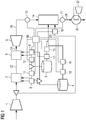
- an ammonia combustion system includes a compressor 1 which compresses air, or other oxygen-containing gas, and passes it into a relatively high-pressure and high-temperature first combustion chamber 2.
- a first mixture of ammonia 4 and hydrogen 5 are added to the first combustion chamber 2 where combustion takes place producing heat and an exhaust gas flow 22.
- the operational pressure within the first combustion chamber 2 may lie in the range 8-30 bar, with a typical operational pressure being in the range 12-25 bar.
- the exit temperature of exhause gases 22 from the first combustion chamber may be in the range 1400-2100 K, typically 1500-1800 K.
- Control of the ratio of ammonia to hydrogen supplied to the first combustion chamber 2 is achieved by a controller 180 through mass flow controllers 8 and 11.
- the ammonia is provided at an enhanced equivalence ratio, for example in the range 1.0-1.2. Due to the enhanced equivalance ratio, exhaust gases 22 from the first combustion chamber 2 contain a significant proportion of NH 2 - ions.
- the exhaust gases 22 from the first combustion chamber are provided to a second combustion chamber 3 along with additional ammonia 4 and hydrogen 5.
- Control of the ratio of ammonia to hydrogen supplied to the second combustion chamber 3 is achieved by a controller 180 through mass flow controllers 9 and 12.
- the gas mixture is optimized to deliver maximum power upon combustion, as the exhaust gas flow 24 is provided to turbine 6 to produce a mechanical output, such as rotation of a shaft.
- the operational pressure within the second combustion chamber 3 may lie in the range 10-30 bar, with a typical operational pressure being in the range 12-25 bar.
- the exit temperature of exhaust gases 24 from the second combustion chamber 3 may be in the range 1400-2100 K, typically 1500-1800 K.
- the combustion may be performed at a relatively constant presssure, for example the combustion presure drop may be less than 5% to maintain cycle efficiency, so there is only a small pressure drop over the combustion chamber.
- the exhaust gas flow 24 from the second combustion chamber 3 will have high levels of nitrogen oxides NO x .
- Exhaust gas 26 leaving the first turbine 6 is hot and is routed to a third combustion chamber 14 operating in a relatively low pressure and relatively low temperature regime.
- the operational pressure within the third combustion chamber 14 may lie in the range 1-10 bar, with a typical operational pressure being in the range 1-5 bar.
- the exit temperature of exhaust gases from the third combustion chamber may be in the range 300-1300 K, typically 750-880 K.
- the exhaust gas 26 containing nitrogen oxides NO x Prior to entering this third combustion chamber, the exhaust gas 26 containing nitrogen oxides NO x , from the second combustion chamber 3 and turbine 6 may be measured with an in situ gas analysis sensor 13.
- a third mixture of ammonia 4 and hydrogen 5, this time with added air 20 is injected into the third combustion chamber 14 with an enhanced equivalence ratio of ammonia, typically 1.0 - 1.2, that is, an excess of ammonia over that required to react with the supplied hydrogen and oxygen to produce only N 2 and H 2 O.
- the mixture is combusted.
- the enhanced equivalence ratio ensures that the combustion produces significant proportion of NH 2 - ions which combine with the nitrogen oxides NO x in the exhaust gas 26 to produce N 2 and H 2 O thereby removing the NO x from the exhaust stream 26 and producing an exhaust stream 28 from the third combustion chamber 14 which has a low content of nitrogen oxides NO x .
- the exact fuel ratio of ammonia 4 to hydrogen 5 supplied to the third combustion chamber 14 is set by controller 180 using mass flow devices 17, 18 and mass flow sensors 15, 16 and optionally a mass flow controller 19 for the air or other oxygen-containing gas, in conjunction with an in situ gas analysis sensor 21 to control the ammonia to hydrogen ratio, and optionally also the proportion of oxygen-containing gas such as air, in the gas mixture supplied to the third combustion chamber 14.
- Controller 180 receives data from sensors 13, 21 and issues appropriate commands to mass flow devices 17, 18 and optionally 19. Controller 180 may be the same controller as the controller associated with mass flow devices 8, 9, 11, 12, or may be a separate controller.
- a heat exchanger 30 may be used to remove waste heat and recover energy from exhaust gases 28 from the third combustion chamber.
- this may be achieved by recovering heat in heat exchanger 30 and using this to drive a steam turbine 32, although other mechanisms may be provided to recover energy from the waste heat, as appropriate.
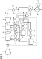
- exhaust gases 22 from the first combustion chamber 2 may be routed through a second turbine 34 to recover waste energy as mechanical rotation.
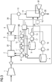
- Fig. 3 shows another embodiment of the present invention.
- third combustion chamber 14 has an integrated heat exchanger. This may be similar to a heat recovery steam generator with supplementary firing. This may be used to drive steam turbine 32, although other mechanisms may be provided to recover energy from the waste heat, as appropriate.
- a heat recovery steam generator is a heat exchanger designed to recover the exhaust 'waste' heat from power generation plant prime movers, such as gas turbines or large reciprocating engines, thus improving overall energy efficiencies.
- Supplementary (or 'duct') firing uses hot gas turbine exhaust gases as the oxygen source, to provide additional energy to generate more steam if and when required. It is an economically attractive way of increasing system output and flexibility. Supplementary firing can provide extra electrical output at lower capital cost and is suitable for peaking.
- a burner is usually, but not always, located in the exhaust gas stream leading to the HRSG. Extra oxygen (or air) can be added if necessary. At high ambient temperatures, a small duct burner can supplement gas turbine exhaust energy to maintain the designed throttle flow to the steam turbine.
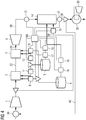
- a recirculation line 40 may be provided to recirculate a proportion of the exhaust gas from the third combustion chamber 14 back into the first combustion chamber 2.
- the recirculated exhaust gas may be combined with the input gas flow, for example by mixing with intake oxygen-containing gas at mixer 36. This has the advantage that unburnt NH 3 in the exhaust gas is recycled and combusted.
- the proportion of the exhaust gas may be varied, for example between 0% and 80%, depending on the proportion of unburnt NH 3 in the exhaust gas from the third combustion chamber, and the acceptable proportion of NH 3 in exhaust gases from the system.
- Measurement 13 of the NO x content in the exhaust gas 26 from turbine 6 prior to input into the third combustion chamber control of the NH 3 /H 2 gas mass flows into each combustion chamber and measurement 21 of the NO x exhaust gas at the output of the third combustion chamber allow the exact setting of the equivalence ratio according to the NO x content of each respective exhaust gas 26, 28.
- Recirculation of exhaust gas from the third combusion chamber 14 back to the first combustion chamber 2 acts to minimize NH 3 emissions.
- the present invention accordingly provides a method for combustion of ammonia, wherein a first combusion chamber receives ammonia and hydrogen in controlled proportions, and an oxygen-containing gas such as air, wherein combustion of the ammonia and hydrogen is carried out so as to produce NH 2 - ions, among other combustion products.
- a second combustion chamber receives the NH 2 - ions and other combustion products along with further ammonia and hydrogen in further controlled proportions, and produces nitrogen oxides, among other combustion products.
- a third combustion chamber receives the combustion products of the second combustion chamber including nitrogen oxides along with further ammonia and hydrogen in further controlled proportions and further oxygen-containing gas such as air, such that the nitrogen oxides are combusted into nitrogen and water.
- Energy from the combustion in the first combustion chamber 2 may be recovered by operation of a turbine 34 to convert the energy released by combustion in the first combustion chamber into mechanical energy.
- Energy from the combustion in the second combustion chamber 3 may be recovered by operation of a turbine 6 to convert the energy released by combustion in the second combustion chamber into mechanical energy.
- Energy from the combustion in the third combustion chamber 14 may be recovered by operation of a turbine 32 to convert the energy released by combustion in the third combustion chamber 14 into mechanical energy. Operation of the turbine 32 may be by direct action of exhaust gases from the third combustion chamber 14 on the turbine 32, or by heating of water in a heat exchanger 30 to drive third turbine 32 by steam.
- the third combustion chamber 14 may incorporate a heat exhanger for recovery of heat from exhaust gases from the third combustion chamber.
- the heat exchanger may serve to heat steam for the recovery of energy.
- a proportion of exhaust gases from the third combustion chamber 14 may be recirculated into the first combustion chamber 2 in order to provide combustion to ammonia remaining in the exhaust gases 28.
Landscapes
- Engineering & Computer Science (AREA)
- Chemical & Material Sciences (AREA)
- Combustion & Propulsion (AREA)
- Mechanical Engineering (AREA)
- General Engineering & Computer Science (AREA)
- Life Sciences & Earth Sciences (AREA)
- Sustainable Development (AREA)
- Engine Equipment That Uses Special Cycles (AREA)
- Combustion Of Fluid Fuel (AREA)
Description
- Ammonia may be used as an energy storage material. Ammonia may be synthesised and stored for later combustion. Combustion of ammonia in a gas turbine, such as disclosed in
JP 2014 185583 A - The present invention provides a system and method for combustion of ammonia which reduces or eliminates the emission of nitrogen oxides NOx.
- The present invention accordingly provides apparatus and methods as set out in the appended claims.
- The above, and further, objects, characteristics and advantages of the present invention will become more apparent from the following description of certain embodiments thereof, given by way of non-limiting examples only, in conjunction with the appended drawings, wherein:
-
Figs. 1-4 schematically illustrate respective embodiments of the present invention. - In a certain embodiment of the invention, illustrated in
Fig. 1 , an ammonia combustion system includes a compressor 1 which compresses air, or other oxygen-containing gas, and passes it into a relatively high-pressure and high-temperaturefirst combustion chamber 2. A first mixture ofammonia 4 andhydrogen 5 are added to thefirst combustion chamber 2 where combustion takes place producing heat and anexhaust gas flow 22. For example, the operational pressure within thefirst combustion chamber 2 may lie in the range 8-30 bar, with a typical operational pressure being in the range 12-25 bar. The exit temperature ofexhause gases 22 from the first combustion chamber may be in the range 1400-2100 K, typically 1500-1800 K. - Control of the ratio of ammonia to hydrogen supplied to the
first combustion chamber 2 is achieved by acontroller 180 throughmass flow controllers - The ammonia is provided at an enhanced equivalence ratio, for example in the range 1.0-1.2. Due to the enhanced equivalance ratio,
exhaust gases 22 from thefirst combustion chamber 2 contain a significant proportion of NH2 - ions. - The
exhaust gases 22 from the first combustion chamber are provided to a second combustion chamber 3 along withadditional ammonia 4 andhydrogen 5. - Control of the ratio of ammonia to hydrogen supplied to the second combustion chamber 3 is achieved by a
controller 180 throughmass flow controllers exhaust gas flow 24 is provided to turbine 6 to produce a mechanical output, such as rotation of a shaft. - For example, the operational pressure within the second combustion chamber 3 may lie in the range 10-30 bar, with a typical operational pressure being in the range 12-25 bar. The exit temperature of
exhaust gases 24 from the second combustion chamber 3 may be in the range 1400-2100 K, typically 1500-1800 K. The combustion may be performed at a relatively constant presssure, for example the combustion presure drop may be less than 5% to maintain cycle efficiency, so there is only a small pressure drop over the combustion chamber. - However, due to high combustion temperatures, and the high nitrogen content of the ammonia fuel, the
exhaust gas flow 24 from the second combustion chamber 3 will have high levels of nitrogen oxides NOx. -
Exhaust gas 26 leaving the first turbine 6 is hot and is routed to athird combustion chamber 14 operating in a relatively low pressure and relatively low temperature regime. For example, the operational pressure within thethird combustion chamber 14 may lie in the range 1-10 bar, with a typical operational pressure being in the range 1-5 bar. The exit temperature of exhaust gases from the third combustion chamber may be in the range 300-1300 K, typically 750-880 K. - Prior to entering this third combustion chamber, the
exhaust gas 26 containing nitrogen oxides NOx, from the second combustion chamber 3 and turbine 6 may be measured with an in situgas analysis sensor 13. - A third mixture of
ammonia 4 andhydrogen 5, this time with addedair 20 is injected into thethird combustion chamber 14 with an enhanced equivalence ratio of ammonia, typically 1.0 - 1.2, that is, an excess of ammonia over that required to react with the supplied hydrogen and oxygen to produce only N2 and H2O. The mixture is combusted. The enhanced equivalence ratio ensures that the combustion produces significant proportion of NH2 - ions which combine with the nitrogen oxides NOx in theexhaust gas 26 to produce N2 and H2O thereby removing the NOx from theexhaust stream 26 and producing anexhaust stream 28 from thethird combustion chamber 14 which has a low content of nitrogen oxides NOx. - The exact fuel ratio of
ammonia 4 tohydrogen 5 supplied to thethird combustion chamber 14 is set bycontroller 180 usingmass flow devices mass flow sensors mass flow controller 19 for the air or other oxygen-containing gas, in conjunction with an in situgas analysis sensor 21 to control the ammonia to hydrogen ratio, and optionally also the proportion of oxygen-containing gas such as air, in the gas mixture supplied to thethird combustion chamber 14. - The required equivalence ratio is determined by measurement of the input NOx proportion by
gas sensor 13 and by measurement of the output NOx emissions measured by insitu gas sensor 21.Controller 180 receives data fromsensors mass flow devices Controller 180 may be the same controller as the controller associated withmass flow devices - Optionally, and in the illustrated embodiment, a
heat exchanger 30 may be used to remove waste heat and recover energy fromexhaust gases 28 from the third combustion chamber. - In the illustrated example, this may be achieved by recovering heat in
heat exchanger 30 and using this to drive asteam turbine 32, although other mechanisms may be provided to recover energy from the waste heat, as appropriate. - In another embodiment of the present invention, as illustrated in
Fig. 2 ,exhaust gases 22 from thefirst combustion chamber 2 may be routed through asecond turbine 34 to recover waste energy as mechanical rotation. -
Fig. 3 shows another embodiment of the present invention. In this embodiment,third combustion chamber 14 has an integrated heat exchanger. This may be similar to a heat recovery steam generator with supplementary firing. This may be used to drivesteam turbine 32, although other mechanisms may be provided to recover energy from the waste heat, as appropriate. - A heat recovery steam generator (HRSG) is a heat exchanger designed to recover the exhaust 'waste' heat from power generation plant prime movers, such as gas turbines or large reciprocating engines, thus improving overall energy efficiencies. Supplementary (or 'duct') firing uses hot gas turbine exhaust gases as the oxygen source, to provide additional energy to generate more steam if and when required. It is an economically attractive way of increasing system output and flexibility. Supplementary firing can provide extra electrical output at lower capital cost and is suitable for peaking. A burner is usually, but not always, located in the exhaust gas stream leading to the HRSG. Extra oxygen (or air) can be added if necessary. At high ambient temperatures, a small duct burner can supplement gas turbine exhaust energy to maintain the designed throttle flow to the steam turbine.
- In a further embodiment of the present invention, illustrated in
Fig. 4 , arecirculation line 40 may be provided to recirculate a proportion of the exhaust gas from thethird combustion chamber 14 back into thefirst combustion chamber 2. The recirculated exhaust gas may be combined with the input gas flow, for example by mixing with intake oxygen-containing gas atmixer 36. This has the advantage that unburnt NH3 in the exhaust gas is recycled and combusted. The proportion of the exhaust gas may be varied, for example between 0% and 80%, depending on the proportion of unburnt NH3 in the exhaust gas from the third combustion chamber, and the acceptable proportion of NH3 in exhaust gases from the system. - The present invention accordingly aims to provide one or more of the following advantages:
- (1) - nitrogen oxides NOx content is reduced or eliminated from the exhaust gases;
- (2) - overall efficiency of the system is maximised as all ammonia and hydrogen is converted to energy, nitrogen and water;
- (3) - gas mixtures, temperatures and pressures in each of the three combustion chambers may be optimised according to their respective allocated function, providing good overall efficiency of the system;
- (4) - the
combustion chambers - (5) - NH3 content in the exhaust gas is minimised.
- The respective technical features that may contribute to the above advantages are as follows.
- Use of three
combustion chambers first combustion chamber 2, efficient power generation in the second combustion chamber 3 and effective removal of NOx in the third combustion chamber. The subsequent combination of NH2 - ions with NOx in the exhaust gas to form N2 and H2O reduces the ammonia content of the exhaust gas. -
Measurement 13 of the NOx content in theexhaust gas 26 from turbine 6 prior to input into the third combustion chamber, control of the NH3/H2 gas mass flows into each combustion chamber andmeasurement 21 of the NOx exhaust gas at the output of the third combustion chamber allow the exact setting of the equivalence ratio according to the NOx content of eachrespective exhaust gas - This is necessary because the burn conditions in the first and
second combustion chambers 2, 3 will determine the NOx content of theexhaust gases 26. These conditions can change on a dynamic basis and from system to system. - Use of a
heat exchanger 30 minimizes the energy loss associated with the third combustion in thethird combustion chamber 14. - Recirculation of exhaust gas from the
third combusion chamber 14 back to thefirst combustion chamber 2 acts to minimize NH3 emissions. - The present invention accordingly provides a method for combustion of ammonia, wherein a first combusion chamber receives ammonia and hydrogen in controlled proportions, and an oxygen-containing gas such as air, wherein combustion of the ammonia and hydrogen is carried out so as to produce NH2 - ions, among other combustion products. A second combustion chamber receives the NH2 - ions and other combustion products along with further ammonia and hydrogen in further controlled proportions, and produces nitrogen oxides, among other combustion products. A third combustion chamber receives the combustion products of the second combustion chamber including nitrogen oxides along with further ammonia and hydrogen in further controlled proportions and further oxygen-containing gas such as air, such that the nitrogen oxides are combusted into nitrogen and water.
- Energy from the combustion in the
first combustion chamber 2 may be recovered by operation of aturbine 34 to convert the energy released by combustion in the first combustion chamber into mechanical energy. - Energy from the combustion in the second combustion chamber 3 may be recovered by operation of a turbine 6 to convert the energy released by combustion in the second combustion chamber into mechanical energy.
- Energy from the combustion in the
third combustion chamber 14 may be recovered by operation of aturbine 32 to convert the energy released by combustion in thethird combustion chamber 14 into mechanical energy. Operation of theturbine 32 may be by direct action of exhaust gases from thethird combustion chamber 14 on theturbine 32, or by heating of water in aheat exchanger 30 to drivethird turbine 32 by steam. - The
third combustion chamber 14 may incorporate a heat exhanger for recovery of heat from exhaust gases from the third combustion chamber. The heat exchanger may serve to heat steam for the recovery of energy. - A proportion of exhaust gases from the
third combustion chamber 14 may be recirculated into thefirst combustion chamber 2 in order to provide combustion to ammonia remaining in theexhaust gases 28. - While the present application has been described with reference to a limited number of particular embodiments, numerous modifications and variants will be apparent to those skilled in the art, within the scope of the appended claims.
Claims (14)
- A method for the combustion of ammonia, wherein a first combustion chamber (2) receives ammonia (4) and hydrogen (5) in controlled proportions, and an oxygen-containing gas, wherein combustion of the ammonia and hydrogen produces NH2 - ions among other combustion products (22), and wherein a second combustion chamber (3) receives the combustion products (22) from the first combustion chamber and receives further ammonia (4) and further hydrogen (5) in controlled proportions, wherein combustion in the second combustion chamber produces nitrogen oxides among other combustion products (24), and wherein a third combustion chamber (14) receives the combustion products (24) of the second combustion chamber including nitrogen oxides along with further ammonia and further hydrogen in further controlled proportions along with further oxygen-containing gas, such that the nitrogen oxides are combusted into nitrogen and water.
- A method for the combustion of ammonia according to claim 1 wherein energy from the combustion in the second combustion chamber (3) is recovered by operation of a first turbine (6) by exhaust gases (24) from the second combustion chamber to convert energy released by combustion in the second combustion chamber into mechanical energy.
- A method for the combustion of ammonia according to claim 2 wherein energy from the combustion in the first combustion chamber (2) is recovered by operation of a second turbine (34) by exhaust gases (24) from the first combustion chamber (2) to convert the energy released by combustion in the first combustion chamber into mechanical energy.
- A method for the combustion of ammonia according to any preceding claim wherein energy from the combustion in the third combustion chamber (14) is recovered by operation of a third turbine (32) to convert the energy released by combustion in the third combustion chamber into mechanical energy.
- A method for the combustion of ammonia according to claim 4 wherein operation of the third turbine (32) is by heating of water in a heat exchanger (30) to drive the third turbine (32) by steam.
- A method for the combustion of ammonia according to any preceding claim wherein heat is recovered from the third combustion chamber (14) by an integrated heat exchanger.
- A method for the combustion of ammonia according to any preceding claim, wherein a proportion of exhaust gases from the third combustion chamber are recirculated (40) into the first combustion chamber (2) in order to provide combustion of ammonia remaining in the exhaust gases.
- A system for the combustion of ammonia, comprising:- a first combustion chamber (2) connected to a source of ammonia (4), to receive ammonia, and connected to a source (5) of hydrogen, to receive hydrogen, in controlled proportions, and connected to a source (1) of an oxygen-containing gas, to receive an oxygen-containing gas;- a second combustion chamber (3) connected to the first combustion chamber to receive exhaust gases (22) from the first combustion chamber, and connected to the source of ammonia to receive further ammonia, and connected to the source of hydrogen to receive further hydrogen in further controlled proportions; and- a third combustion chamber (14) connected to the second combustion chamber to receive exhaust gases (26) from the second combustion chamber, and connected to the source of ammonia to receive further ammonia and, and connected to the source of hydrogen to receive further hydrogen in further controlled proportions, and connected to the source (1) of oxygen-containing gas to receive further oxygen-containing gas.
- A system according to claim 8, further comprising a first turbine (6) connected to receive exhaust gases (24) from the second combustion chamber, to generate a mechanical output and to provide the exhaust gases to the third combustion chamber (13).
- A system according to claim 8 or claim 9 further comprising a second turbine (34) connected to receive exhaust gases (22) from the first combustion chamber (2) and to provide the exhaust gases to the second combustion chamber (3) .
- A system according to claim 10 further comprising a third turbine (32) connected to a heat exchanger (30) which is connected to receive exhaust gases (28) from the third combustion chamber (14), whereby to heat water and generate steam to drive the third turbine (32).
- A system according to claim 11 wherein the heat exchanger is integrated into the third combustion chamber.
- A system for the combustion of ammonia according to any of claims 8-12, further comprising a recirculation line (40) arranged to recirculate a portion of exhaust gas (28) from the third combustion chamber (14) back into the first combustion chamber (2).
- A system for the combustion of ammonia according to claim 13 wherein the recirculation line is connected to a mixer (36) to mix the proportion of recirculated exhaust gas with intake oxygen-containing gas.
Applications Claiming Priority (2)
| Application Number | Priority Date | Filing Date | Title |
|---|---|---|---|
| GB1602617.1A GB2547274B (en) | 2016-02-15 | 2016-02-15 | Method and equipment for combustion of ammonia |
| PCT/EP2017/053036 WO2017140595A1 (en) | 2016-02-15 | 2017-02-10 | Method and equipment for combustion of ammonia |
Publications (2)
| Publication Number | Publication Date |
|---|---|
| EP3417205A1 EP3417205A1 (en) | 2018-12-26 |
| EP3417205B1 true EP3417205B1 (en) | 2019-11-06 |
Family
ID=55697681
Family Applications (1)
| Application Number | Title | Priority Date | Filing Date |
|---|---|---|---|
| EP17705089.5A Active EP3417205B1 (en) | 2016-02-15 | 2017-02-10 | Method and equipment for combustion of ammonia |
Country Status (9)
| Country | Link |
|---|---|
| US (1) | US10767556B2 (en) |
| EP (1) | EP3417205B1 (en) |
| JP (1) | JP6632737B2 (en) |
| KR (1) | KR102096259B1 (en) |
| CN (1) | CN108700288B (en) |
| AU (1) | AU2017219691B2 (en) |
| CA (1) | CA3012085C (en) |
| GB (1) | GB2547274B (en) |
| WO (1) | WO2017140595A1 (en) |
Cited By (4)
| Publication number | Priority date | Publication date | Assignee | Title |
|---|---|---|---|---|
| WO2024223214A1 (en) | 2023-04-28 | 2024-10-31 | Siemens Energy Global GmbH & Co. KG | Gas turbine arrangement with ammonia cracker and power plant with such and method to operate a gas turbine arrangement |
| WO2024223225A1 (en) | 2023-04-28 | 2024-10-31 | Siemens Energy Global GmbH & Co. KG | Gas turbine arrangement with ammonia cracker and power plant with such and method to operate a gas turbine arrangement |
| WO2024251509A1 (en) | 2023-06-07 | 2024-12-12 | Siemens Energy Global GmbH & Co. KG | Gas turbine arrangement with ammonia cracker and power plant with such and method to operate a gas turbine arrangement |
| DE102023209964A1 (en) | 2023-06-07 | 2024-12-12 | Siemens Energy Global GmbH & Co. KG | Combustion device and gas turbine with ammonia cracker and method for operating a combustion device and gas turbine |
Families Citing this family (13)
| Publication number | Priority date | Publication date | Assignee | Title |
|---|---|---|---|---|
| JP7385476B2 (en) * | 2020-01-06 | 2023-11-22 | 株式会社Kri | Ammonia combustion equipment and ammonia fuel cell system |
| CN112902163B (en) * | 2021-03-08 | 2022-04-22 | 山东大学 | Hydrogen-doped low-nitrogen combustion system and method based on ammonia decomposition |
| MX2024010101A (en) * | 2022-03-03 | 2024-08-28 | Nooter/Eriksen Inc | Thermal energy storage system and method with heat recovery steam generator. |
| US12222106B2 (en) | 2022-03-30 | 2025-02-11 | Ge Infrastructure Technology Llc | Ammonia fired combustor operating method |
| CN114876654B (en) * | 2022-06-17 | 2023-09-26 | 天津大学 | Control method of engine adopting ammonia and hydrogen dual fuel |
| CN115585061B (en) * | 2022-10-18 | 2023-06-02 | 南京工程学院 | All-weather cold-heat-power poly-generation system and method based on ammonia synthesis and cracking |
| KR102897161B1 (en) | 2023-05-30 | 2025-12-09 | 두산에너빌리티 주식회사 | Gas turbine plant with ammonia decomposition system |
| KR102921605B1 (en) | 2023-05-30 | 2026-02-02 | 두산에너빌리티 주식회사 | Gas turbine plant with ammonia decomposition system |
| KR20240171446A (en) | 2023-05-30 | 2024-12-09 | 두산에너빌리티 주식회사 | Gas turbine plant with ammonia decomposition system |
| KR102897162B1 (en) | 2023-05-30 | 2025-12-09 | 두산에너빌리티 주식회사 | Gas turbine plant with ammonia decomposition system |
| US12264621B2 (en) | 2023-05-30 | 2025-04-01 | Doosan Enerbility Co., Ltd. | Gas turbine plant with ammonia decomposition system |
| US12385433B2 (en) * | 2023-05-30 | 2025-08-12 | Doosan Enerbility Co., Ltd. | Gas turbine plant with ammonia decomposition system |
| US12281620B1 (en) * | 2024-06-05 | 2025-04-22 | Ge Infrastructure Technology Llc | System and method for blending multiple fuels |
Family Cites Families (19)
| Publication number | Priority date | Publication date | Assignee | Title |
|---|---|---|---|---|
| GB1537109A (en) * | 1975-10-23 | 1978-12-29 | Gen Electric | Gas turbine combustion system |
| GB2116531B (en) * | 1982-03-11 | 1985-11-20 | Shell Int Research | Process and apparatus for the combustion of ammonia-containing waste gases |
| US4910957A (en) * | 1988-07-13 | 1990-03-27 | Prutech Ii | Staged lean premix low nox hot wall gas turbine combustor with improved turndown capability |
| US6432368B1 (en) * | 1994-06-30 | 2002-08-13 | General Electric Company | Staged catalytic ammonia decomposition in integrated gasification combined cycle systems |
| WO2001087770A1 (en) * | 2000-05-12 | 2001-11-22 | Gradient Technology | Production of hydrogen by autothermic decomposition of ammonia |
| JP3924150B2 (en) * | 2001-10-26 | 2007-06-06 | 三菱重工業株式会社 | Gas combustion treatment method and apparatus |
| US6790030B2 (en) * | 2001-11-20 | 2004-09-14 | The Regents Of The University Of California | Multi-stage combustion using nitrogen-enriched air |
| US8220268B2 (en) * | 2007-11-28 | 2012-07-17 | Caterpillar Inc. | Turbine engine having fuel-cooled air intercooling |
| JP5024460B2 (en) * | 2009-01-14 | 2012-09-12 | トヨタ自動車株式会社 | engine |
| US8623285B2 (en) * | 2010-05-27 | 2014-01-07 | Shawn Grannell | Ammonia flame cracker system, method and apparatus |
| US8899969B2 (en) * | 2011-06-09 | 2014-12-02 | Gas Technology Institute | Method and system for low-NOx dual-fuel combustion of liquid and/or gaseous fuels |
| JP2012255420A (en) | 2011-06-10 | 2012-12-27 | Nippon Shokubai Co Ltd | Gas turbine system |
| EP2589426B1 (en) | 2011-11-02 | 2016-06-08 | Casale Sa | Method for removing nitrogen oxides from combustion fumes with on-site generation of ammonia |
| EP2642097A1 (en) * | 2012-03-21 | 2013-09-25 | Alstom Technology Ltd | Method for operating a gas turbine and gas turbine for carrying out the method |
| WO2014127913A2 (en) * | 2013-02-21 | 2014-08-28 | Faramarz Bairamijamal | High pressure process for co2 capture, utilization for heat recovery, power cycle, super-efficient hydrogen based fossil power generation and conversion of liquid co2 with water to syngas and oxygen |
| JP5900972B2 (en) * | 2013-03-22 | 2016-04-06 | 一般財団法人電力中央研究所 | NH3 cogeneration plant |
| CN203375458U (en) | 2013-05-30 | 2014-01-01 | 晶澳太阳能有限公司 | Silicane waste gas burning tower used in production process of solar cell |
| JP6153163B2 (en) | 2013-08-02 | 2017-06-28 | 一般財団法人電力中央研究所 | Reheat type ammonia gas turbine |
| CA2937943A1 (en) * | 2014-02-12 | 2015-08-20 | Praxair Technology, Inc. | Oxygen transport membrane reactor based method and system for generating electric power |
-
2016
- 2016-02-15 GB GB1602617.1A patent/GB2547274B/en not_active Withdrawn - After Issue
-
2017
- 2017-02-10 WO PCT/EP2017/053036 patent/WO2017140595A1/en not_active Ceased
- 2017-02-10 EP EP17705089.5A patent/EP3417205B1/en active Active
- 2017-02-10 US US15/999,280 patent/US10767556B2/en active Active
- 2017-02-10 JP JP2018543125A patent/JP6632737B2/en active Active
- 2017-02-10 CA CA3012085A patent/CA3012085C/en active Active
- 2017-02-10 CN CN201780011628.3A patent/CN108700288B/en active Active
- 2017-02-10 KR KR1020187026600A patent/KR102096259B1/en active Active
- 2017-02-10 AU AU2017219691A patent/AU2017219691B2/en active Active
Non-Patent Citations (1)
| Title |
|---|
| None * |
Cited By (4)
| Publication number | Priority date | Publication date | Assignee | Title |
|---|---|---|---|---|
| WO2024223214A1 (en) | 2023-04-28 | 2024-10-31 | Siemens Energy Global GmbH & Co. KG | Gas turbine arrangement with ammonia cracker and power plant with such and method to operate a gas turbine arrangement |
| WO2024223225A1 (en) | 2023-04-28 | 2024-10-31 | Siemens Energy Global GmbH & Co. KG | Gas turbine arrangement with ammonia cracker and power plant with such and method to operate a gas turbine arrangement |
| WO2024251509A1 (en) | 2023-06-07 | 2024-12-12 | Siemens Energy Global GmbH & Co. KG | Gas turbine arrangement with ammonia cracker and power plant with such and method to operate a gas turbine arrangement |
| DE102023209964A1 (en) | 2023-06-07 | 2024-12-12 | Siemens Energy Global GmbH & Co. KG | Combustion device and gas turbine with ammonia cracker and method for operating a combustion device and gas turbine |
Also Published As
| Publication number | Publication date |
|---|---|
| JP2019510953A (en) | 2019-04-18 |
| CA3012085C (en) | 2020-06-23 |
| GB2547274B (en) | 2018-03-28 |
| US10767556B2 (en) | 2020-09-08 |
| GB201602617D0 (en) | 2016-03-30 |
| CN108700288B (en) | 2020-07-31 |
| KR102096259B1 (en) | 2020-04-02 |
| US20190107048A1 (en) | 2019-04-11 |
| EP3417205A1 (en) | 2018-12-26 |
| AU2017219691A1 (en) | 2018-08-09 |
| CA3012085A1 (en) | 2017-08-24 |
| AU2017219691B2 (en) | 2020-03-26 |
| GB2547274A (en) | 2017-08-16 |
| JP6632737B2 (en) | 2020-01-22 |
| CN108700288A (en) | 2018-10-23 |
| KR20180112015A (en) | 2018-10-11 |
| WO2017140595A1 (en) | 2017-08-24 |
Similar Documents
| Publication | Publication Date | Title |
|---|---|---|
| CA3012085C (en) | Method and equipment for combustion of ammonia | |
| EP3314166B1 (en) | Method and equipment for combustion of ammonia | |
| US5133180A (en) | Chemically recuperated gas turbine | |
| CN102953819B (en) | Power set and operational approach | |
| JP5906555B2 (en) | Stoichiometric combustion of rich air by exhaust gas recirculation system | |
| CN102979621B (en) | Power plant and method of operation | |
| US6684643B2 (en) | Process for the operation of a gas turbine plant | |
| US9145849B2 (en) | Engine fueled by ammonia with selective reduction catalyst | |
| EP2522829A2 (en) | A steam injected gas turbine engine | |
| EP1186761A2 (en) | Energy recovery from compressor discharge bleed air in gas turbine plants | |
| EP2650512A2 (en) | A method and system for controlling a powerplant during low-load operations | |
| US20140203557A1 (en) | System and Method for Extending Minimum Turn Down Load of Combined Cycle Power Plant | |
| EP2476880A1 (en) | Gas turbine engine and corresponding operating method | |
| WO1998049438A1 (en) | Power plant with partial oxidation and sequential combustion | |
| US8539776B2 (en) | Generating power using an ion transport membrane | |
| EP2578840A2 (en) | Power plant with exhaust gas recirculation system | |
| CN118451245A (en) | Gas turbine system, in particular for an electrically driven motor vehicle, as well as a motor vehicle and a method | |
| JPS62135619A (en) | Heat supply power generating device using gas turbine |
Legal Events
| Date | Code | Title | Description |
|---|---|---|---|
| STAA | Information on the status of an ep patent application or granted ep patent |
Free format text: STATUS: UNKNOWN |
|
| STAA | Information on the status of an ep patent application or granted ep patent |
Free format text: STATUS: THE INTERNATIONAL PUBLICATION HAS BEEN MADE |
|
| PUAI | Public reference made under article 153(3) epc to a published international application that has entered the european phase |
Free format text: ORIGINAL CODE: 0009012 |
|
| STAA | Information on the status of an ep patent application or granted ep patent |
Free format text: STATUS: REQUEST FOR EXAMINATION WAS MADE |
|
| 17P | Request for examination filed |
Effective date: 20180709 |
|
| AK | Designated contracting states |
Kind code of ref document: A1 Designated state(s): AL AT BE BG CH CY CZ DE DK EE ES FI FR GB GR HR HU IE IS IT LI LT LU LV MC MK MT NL NO PL PT RO RS SE SI SK SM TR |
|
| AX | Request for extension of the european patent |
Extension state: BA ME |
|
| DAV | Request for validation of the european patent (deleted) | ||
| DAX | Request for extension of the european patent (deleted) | ||
| GRAP | Despatch of communication of intention to grant a patent |
Free format text: ORIGINAL CODE: EPIDOSNIGR1 |
|
| STAA | Information on the status of an ep patent application or granted ep patent |
Free format text: STATUS: GRANT OF PATENT IS INTENDED |
|
| INTG | Intention to grant announced |
Effective date: 20190717 |
|
| GRAS | Grant fee paid |
Free format text: ORIGINAL CODE: EPIDOSNIGR3 |
|
| GRAA | (expected) grant |
Free format text: ORIGINAL CODE: 0009210 |
|
| STAA | Information on the status of an ep patent application or granted ep patent |
Free format text: STATUS: THE PATENT HAS BEEN GRANTED |
|
| AK | Designated contracting states |
Kind code of ref document: B1 Designated state(s): AL AT BE BG CH CY CZ DE DK EE ES FI FR GB GR HR HU IE IS IT LI LT LU LV MC MK MT NL NO PL PT RO RS SE SI SK SM TR |
|
| REG | Reference to a national code |
Ref country code: GB Ref legal event code: FG4D |
|
| REG | Reference to a national code |
Ref country code: CH Ref legal event code: EP Ref country code: AT Ref legal event code: REF Ref document number: 1199226 Country of ref document: AT Kind code of ref document: T Effective date: 20191115 |
|
| REG | Reference to a national code |
Ref country code: IE Ref legal event code: FG4D |
|
| REG | Reference to a national code |
Ref country code: DE Ref legal event code: R096 Ref document number: 602017008478 Country of ref document: DE |
|
| REG | Reference to a national code |
Ref country code: NL Ref legal event code: MP Effective date: 20191106 |
|
| REG | Reference to a national code |
Ref country code: LT Ref legal event code: MG4D |
|
| REG | Reference to a national code |
Ref country code: CH Ref legal event code: NV Representative=s name: SIEMENS SCHWEIZ AG, CH |
|
| PG25 | Lapsed in a contracting state [announced via postgrant information from national office to epo] |
Ref country code: PL Free format text: LAPSE BECAUSE OF FAILURE TO SUBMIT A TRANSLATION OF THE DESCRIPTION OR TO PAY THE FEE WITHIN THE PRESCRIBED TIME-LIMIT Effective date: 20191106 Ref country code: LV Free format text: LAPSE BECAUSE OF FAILURE TO SUBMIT A TRANSLATION OF THE DESCRIPTION OR TO PAY THE FEE WITHIN THE PRESCRIBED TIME-LIMIT Effective date: 20191106 Ref country code: PT Free format text: LAPSE BECAUSE OF FAILURE TO SUBMIT A TRANSLATION OF THE DESCRIPTION OR TO PAY THE FEE WITHIN THE PRESCRIBED TIME-LIMIT Effective date: 20200306 Ref country code: SE Free format text: LAPSE BECAUSE OF FAILURE TO SUBMIT A TRANSLATION OF THE DESCRIPTION OR TO PAY THE FEE WITHIN THE PRESCRIBED TIME-LIMIT Effective date: 20191106 Ref country code: NO Free format text: LAPSE BECAUSE OF FAILURE TO SUBMIT A TRANSLATION OF THE DESCRIPTION OR TO PAY THE FEE WITHIN THE PRESCRIBED TIME-LIMIT Effective date: 20200206 Ref country code: FI Free format text: LAPSE BECAUSE OF FAILURE TO SUBMIT A TRANSLATION OF THE DESCRIPTION OR TO PAY THE FEE WITHIN THE PRESCRIBED TIME-LIMIT Effective date: 20191106 Ref country code: BG Free format text: LAPSE BECAUSE OF FAILURE TO SUBMIT A TRANSLATION OF THE DESCRIPTION OR TO PAY THE FEE WITHIN THE PRESCRIBED TIME-LIMIT Effective date: 20200206 Ref country code: GR Free format text: LAPSE BECAUSE OF FAILURE TO SUBMIT A TRANSLATION OF THE DESCRIPTION OR TO PAY THE FEE WITHIN THE PRESCRIBED TIME-LIMIT Effective date: 20200207 Ref country code: LT Free format text: LAPSE BECAUSE OF FAILURE TO SUBMIT A TRANSLATION OF THE DESCRIPTION OR TO PAY THE FEE WITHIN THE PRESCRIBED TIME-LIMIT Effective date: 20191106 Ref country code: NL Free format text: LAPSE BECAUSE OF FAILURE TO SUBMIT A TRANSLATION OF THE DESCRIPTION OR TO PAY THE FEE WITHIN THE PRESCRIBED TIME-LIMIT Effective date: 20191106 |
|
| PG25 | Lapsed in a contracting state [announced via postgrant information from national office to epo] |
Ref country code: RS Free format text: LAPSE BECAUSE OF FAILURE TO SUBMIT A TRANSLATION OF THE DESCRIPTION OR TO PAY THE FEE WITHIN THE PRESCRIBED TIME-LIMIT Effective date: 20191106 Ref country code: HR Free format text: LAPSE BECAUSE OF FAILURE TO SUBMIT A TRANSLATION OF THE DESCRIPTION OR TO PAY THE FEE WITHIN THE PRESCRIBED TIME-LIMIT Effective date: 20191106 Ref country code: IS Free format text: LAPSE BECAUSE OF FAILURE TO SUBMIT A TRANSLATION OF THE DESCRIPTION OR TO PAY THE FEE WITHIN THE PRESCRIBED TIME-LIMIT Effective date: 20200306 |
|
| PG25 | Lapsed in a contracting state [announced via postgrant information from national office to epo] |
Ref country code: AL Free format text: LAPSE BECAUSE OF FAILURE TO SUBMIT A TRANSLATION OF THE DESCRIPTION OR TO PAY THE FEE WITHIN THE PRESCRIBED TIME-LIMIT Effective date: 20191106 |
|
| PG25 | Lapsed in a contracting state [announced via postgrant information from national office to epo] |
Ref country code: RO Free format text: LAPSE BECAUSE OF FAILURE TO SUBMIT A TRANSLATION OF THE DESCRIPTION OR TO PAY THE FEE WITHIN THE PRESCRIBED TIME-LIMIT Effective date: 20191106 Ref country code: CZ Free format text: LAPSE BECAUSE OF FAILURE TO SUBMIT A TRANSLATION OF THE DESCRIPTION OR TO PAY THE FEE WITHIN THE PRESCRIBED TIME-LIMIT Effective date: 20191106 Ref country code: EE Free format text: LAPSE BECAUSE OF FAILURE TO SUBMIT A TRANSLATION OF THE DESCRIPTION OR TO PAY THE FEE WITHIN THE PRESCRIBED TIME-LIMIT Effective date: 20191106 Ref country code: DK Free format text: LAPSE BECAUSE OF FAILURE TO SUBMIT A TRANSLATION OF THE DESCRIPTION OR TO PAY THE FEE WITHIN THE PRESCRIBED TIME-LIMIT Effective date: 20191106 Ref country code: ES Free format text: LAPSE BECAUSE OF FAILURE TO SUBMIT A TRANSLATION OF THE DESCRIPTION OR TO PAY THE FEE WITHIN THE PRESCRIBED TIME-LIMIT Effective date: 20191106 |
|
| REG | Reference to a national code |
Ref country code: DE Ref legal event code: R097 Ref document number: 602017008478 Country of ref document: DE |
|
| REG | Reference to a national code |
Ref country code: AT Ref legal event code: MK05 Ref document number: 1199226 Country of ref document: AT Kind code of ref document: T Effective date: 20191106 |
|
| PG25 | Lapsed in a contracting state [announced via postgrant information from national office to epo] |
Ref country code: SK Free format text: LAPSE BECAUSE OF FAILURE TO SUBMIT A TRANSLATION OF THE DESCRIPTION OR TO PAY THE FEE WITHIN THE PRESCRIBED TIME-LIMIT Effective date: 20191106 Ref country code: SM Free format text: LAPSE BECAUSE OF FAILURE TO SUBMIT A TRANSLATION OF THE DESCRIPTION OR TO PAY THE FEE WITHIN THE PRESCRIBED TIME-LIMIT Effective date: 20191106 |
|
| PLBE | No opposition filed within time limit |
Free format text: ORIGINAL CODE: 0009261 |
|
| STAA | Information on the status of an ep patent application or granted ep patent |
Free format text: STATUS: NO OPPOSITION FILED WITHIN TIME LIMIT |
|
| REG | Reference to a national code |
Ref country code: CH Ref legal event code: PL |
|
| 26N | No opposition filed |
Effective date: 20200807 |
|
| REG | Reference to a national code |
Ref country code: BE Ref legal event code: MM Effective date: 20200229 |
|
| PG25 | Lapsed in a contracting state [announced via postgrant information from national office to epo] |
Ref country code: MC Free format text: LAPSE BECAUSE OF FAILURE TO SUBMIT A TRANSLATION OF THE DESCRIPTION OR TO PAY THE FEE WITHIN THE PRESCRIBED TIME-LIMIT Effective date: 20191106 Ref country code: LU Free format text: LAPSE BECAUSE OF NON-PAYMENT OF DUE FEES Effective date: 20200210 |
|
| PG25 | Lapsed in a contracting state [announced via postgrant information from national office to epo] |
Ref country code: CH Free format text: LAPSE BECAUSE OF NON-PAYMENT OF DUE FEES Effective date: 20200229 Ref country code: AT Free format text: LAPSE BECAUSE OF FAILURE TO SUBMIT A TRANSLATION OF THE DESCRIPTION OR TO PAY THE FEE WITHIN THE PRESCRIBED TIME-LIMIT Effective date: 20191106 Ref country code: LI Free format text: LAPSE BECAUSE OF NON-PAYMENT OF DUE FEES Effective date: 20200229 Ref country code: SI Free format text: LAPSE BECAUSE OF FAILURE TO SUBMIT A TRANSLATION OF THE DESCRIPTION OR TO PAY THE FEE WITHIN THE PRESCRIBED TIME-LIMIT Effective date: 20191106 |
|
| REG | Reference to a national code |
Ref country code: DE Ref legal event code: R081 Ref document number: 602017008478 Country of ref document: DE Owner name: SIEMENS ENERGY GLOBAL GMBH & CO. KG, DE Free format text: FORMER OWNER: SIEMENS AKTIENGESELLSCHAFT, 80333 MUENCHEN, DE |
|
| PG25 | Lapsed in a contracting state [announced via postgrant information from national office to epo] |
Ref country code: IE Free format text: LAPSE BECAUSE OF NON-PAYMENT OF DUE FEES Effective date: 20200210 Ref country code: IT Free format text: LAPSE BECAUSE OF FAILURE TO SUBMIT A TRANSLATION OF THE DESCRIPTION OR TO PAY THE FEE WITHIN THE PRESCRIBED TIME-LIMIT Effective date: 20191106 |
|
| PG25 | Lapsed in a contracting state [announced via postgrant information from national office to epo] |
Ref country code: BE Free format text: LAPSE BECAUSE OF NON-PAYMENT OF DUE FEES Effective date: 20200229 |
|
| PG25 | Lapsed in a contracting state [announced via postgrant information from national office to epo] |
Ref country code: TR Free format text: LAPSE BECAUSE OF FAILURE TO SUBMIT A TRANSLATION OF THE DESCRIPTION OR TO PAY THE FEE WITHIN THE PRESCRIBED TIME-LIMIT Effective date: 20191106 Ref country code: MT Free format text: LAPSE BECAUSE OF FAILURE TO SUBMIT A TRANSLATION OF THE DESCRIPTION OR TO PAY THE FEE WITHIN THE PRESCRIBED TIME-LIMIT Effective date: 20191106 Ref country code: CY Free format text: LAPSE BECAUSE OF FAILURE TO SUBMIT A TRANSLATION OF THE DESCRIPTION OR TO PAY THE FEE WITHIN THE PRESCRIBED TIME-LIMIT Effective date: 20191106 |
|
| PG25 | Lapsed in a contracting state [announced via postgrant information from national office to epo] |
Ref country code: MK Free format text: LAPSE BECAUSE OF FAILURE TO SUBMIT A TRANSLATION OF THE DESCRIPTION OR TO PAY THE FEE WITHIN THE PRESCRIBED TIME-LIMIT Effective date: 20191106 |
|
| REG | Reference to a national code |
Ref country code: GB Ref legal event code: 732E Free format text: REGISTERED BETWEEN 20220901 AND 20220907 |
|
| P01 | Opt-out of the competence of the unified patent court (upc) registered |
Effective date: 20231222 |
|
| PGFP | Annual fee paid to national office [announced via postgrant information from national office to epo] |
Ref country code: GB Payment date: 20260223 Year of fee payment: 10 |
|
| PGFP | Annual fee paid to national office [announced via postgrant information from national office to epo] |
Ref country code: DE Payment date: 20260220 Year of fee payment: 10 |
|
| PGFP | Annual fee paid to national office [announced via postgrant information from national office to epo] |
Ref country code: FR Payment date: 20260224 Year of fee payment: 10 |