EP3417127B1 - Apparatus and method for fastening a composite pole to the ground - Google Patents
Apparatus and method for fastening a composite pole to the ground Download PDFInfo
- Publication number
- EP3417127B1 EP3417127B1 EP17725370.5A EP17725370A EP3417127B1 EP 3417127 B1 EP3417127 B1 EP 3417127B1 EP 17725370 A EP17725370 A EP 17725370A EP 3417127 B1 EP3417127 B1 EP 3417127B1
- Authority
- EP
- European Patent Office
- Prior art keywords
- fastening element
- ground
- fastening
- slit
- formed opening
- Prior art date
- Legal status (The legal status is an assumption and is not a legal conclusion. Google has not performed a legal analysis and makes no representation as to the accuracy of the status listed.)
- Active
Links
Images



Classifications
-
- E—FIXED CONSTRUCTIONS
- E04—BUILDING
- E04H—BUILDINGS OR LIKE STRUCTURES FOR PARTICULAR PURPOSES; SWIMMING OR SPLASH BATHS OR POOLS; MASTS; FENCING; TENTS OR CANOPIES, IN GENERAL
- E04H12/00—Towers; Masts or poles; Chimney stacks; Water-towers; Methods of erecting such structures
- E04H12/22—Sockets or holders for poles or posts
- E04H12/2207—Sockets or holders for poles or posts not used
- E04H12/2215—Sockets or holders for poles or posts not used driven into the ground
- E04H12/223—Sockets or holders for poles or posts not used driven into the ground with movable anchoring elements; with separately driven anchor rods
-
- E—FIXED CONSTRUCTIONS
- E04—BUILDING
- E04H—BUILDINGS OR LIKE STRUCTURES FOR PARTICULAR PURPOSES; SWIMMING OR SPLASH BATHS OR POOLS; MASTS; FENCING; TENTS OR CANOPIES, IN GENERAL
- E04H12/00—Towers; Masts or poles; Chimney stacks; Water-towers; Methods of erecting such structures
- E04H12/22—Sockets or holders for poles or posts
-
- E—FIXED CONSTRUCTIONS
- E02—HYDRAULIC ENGINEERING; FOUNDATIONS; SOIL SHIFTING
- E02D—FOUNDATIONS; EXCAVATIONS; EMBANKMENTS; UNDERGROUND OR UNDERWATER STRUCTURES
- E02D27/00—Foundations as substructures
- E02D27/32—Foundations for special purposes
- E02D27/42—Foundations for poles, masts or chimneys
-
- E—FIXED CONSTRUCTIONS
- E01—CONSTRUCTION OF ROADS, RAILWAYS, OR BRIDGES
- E01F—ADDITIONAL WORK, SUCH AS EQUIPPING ROADS OR THE CONSTRUCTION OF PLATFORMS, HELICOPTER LANDING STAGES, SIGNS, SNOW FENCES, OR THE LIKE
- E01F9/00—Arrangement of road signs or traffic signals; Arrangements for enforcing caution
- E01F9/60—Upright bodies, e.g. marker posts or bollards; Supports for road signs
- E01F9/658—Upright bodies, e.g. marker posts or bollards; Supports for road signs characterised by means for fixing
- E01F9/673—Upright bodies, e.g. marker posts or bollards; Supports for road signs characterised by means for fixing for holding sign posts or the like
- E01F9/685—Subsoil means, e.g. foundations
-
- E—FIXED CONSTRUCTIONS
- E04—BUILDING
- E04H—BUILDINGS OR LIKE STRUCTURES FOR PARTICULAR PURPOSES; SWIMMING OR SPLASH BATHS OR POOLS; MASTS; FENCING; TENTS OR CANOPIES, IN GENERAL
- E04H12/00—Towers; Masts or poles; Chimney stacks; Water-towers; Methods of erecting such structures
- E04H12/22—Sockets or holders for poles or posts
- E04H12/2207—Sockets or holders for poles or posts not used
- E04H12/2215—Sockets or holders for poles or posts not used driven into the ground
-
- E—FIXED CONSTRUCTIONS
- E04—BUILDING
- E04H—BUILDINGS OR LIKE STRUCTURES FOR PARTICULAR PURPOSES; SWIMMING OR SPLASH BATHS OR POOLS; MASTS; FENCING; TENTS OR CANOPIES, IN GENERAL
- E04H12/00—Towers; Masts or poles; Chimney stacks; Water-towers; Methods of erecting such structures
- E04H12/22—Sockets or holders for poles or posts
- E04H12/2253—Mounting poles or posts to the holder
- E04H12/2269—Mounting poles or posts to the holder in a socket
-
- E—FIXED CONSTRUCTIONS
- E04—BUILDING
- E04H—BUILDINGS OR LIKE STRUCTURES FOR PARTICULAR PURPOSES; SWIMMING OR SPLASH BATHS OR POOLS; MASTS; FENCING; TENTS OR CANOPIES, IN GENERAL
- E04H12/00—Towers; Masts or poles; Chimney stacks; Water-towers; Methods of erecting such structures
- E04H12/22—Sockets or holders for poles or posts
- E04H12/2253—Mounting poles or posts to the holder
- E04H12/2276—Clamping poles or posts on a stub
-
- E—FIXED CONSTRUCTIONS
- E04—BUILDING
- E04H—BUILDINGS OR LIKE STRUCTURES FOR PARTICULAR PURPOSES; SWIMMING OR SPLASH BATHS OR POOLS; MASTS; FENCING; TENTS OR CANOPIES, IN GENERAL
- E04H12/00—Towers; Masts or poles; Chimney stacks; Water-towers; Methods of erecting such structures
- E04H12/02—Structures made of specified materials
Definitions
- This invention relates to an apparatus for fastening a hollow composite pole to the ground where a slit formed opening is present in the ground.
- the invention also relates to a method for fastening a hollow composite pole to the ground.
- the column may be made from concrete and having reinforcement that extends into the ground.
- the composite pole may be inserted over the column. If the column is made from concrete, it is necessary to bring the concrete to the position of the column often by use of a helicopter, or make concrete at the position of the column. Both methods comprises extra costs and work.
- WO2004/101914 discloses a hollow pole that is drilled into a slit the ground.
- the invention has for its object to remedy or to reduce at least one of the drawbacks of the prior art, or at least provide a useful alternative to prior art.
- the invention relates more particularly to fastening element in accordance with claim 1.
- the invention concerns having a circular slit-formed opening, in the ground, where a fastening element is positioned in the slit-formed opening.
- the fastening element has a conical upper portion above the ground and a lower cylindrical end portion.
- a hollow composite pole has a complementary conical inner portion at its lower end, and is positioned on and abutting the fastening element.
- hollow means that the composite pole must have an inner opening, at least in the portion that is moved over the fastening element.
- the slit formed opening may be formed by drilling or hammering a body into the ground.
- the fastening element may be equipped with drill elements at its lower end portion to enable the fastening element to be used as a drill.
- the drill elements may comprise metal or ceramic material or combinations thereof.
- the invention relates more particularly to a method for fastening a hollow composite pole for overhead power lines to the ground in accordance with claim 6.
- the method comprises fixing the fastening element to the ground, for instance by adhesive or a concrete based material.
- the method may comprise making the slit formed opening by drilling into the ground.
- the method may comprise making the slit formed opening by hammering the fastening element into the ground.
- the method comprises providing the lower end portion of the fastening element with drill elements and drilling the fastening element into the ground.
- the fastening element may be made from composite material or metal or combinations thereof.
- the material on the inner side of the slit may be at least partly removed.
- frost in the ground When drilling in soil or march, it may be advantageous to have frost in the ground to avoid movement in the ground during drilling.
- Tests show that the drill or the fastening element must be aligned with the vertical axes prior to being moved into the ground.
- the apparatus and method according to invention solves the problem of fastening a hollow composite pole to the ground in a relatively simple and cost effective way.
- the reference numeral 1 denotes a drill that by the help of a power drill 2 is under displacement into the ground 4.
- the ground 4 may constitute for example rock, soil, or march, alternatively combination thereof.
- the power drill 2 is typically aligned and is fixed to the ground 4 or another suitable, not shown device. There after the power drill 2 that may be electrically or hydraulically driven, displaces the drill 1 into the ground 4 while rotating the drill 1. Thus, a slit formed opening 6 is formed in the ground 4. The drill 1 is then removed from the slit formed opening 6.
- a composite pole 8 that has been moved into the slit formed opening 6 is shown in fig. 2 . Additional fixing of the composite pole 8 to the ground 4 may be achieved by inserting grouting, fixing compound or other material (not shown) in between the composite pole 8 and the ground 4.
- a sleeve formed fastening element 10 is positioned in the slit formed opening 6. Additional fixing of the fixing element 10 to the ground 4 may be carried out as described for the composite pole 8.
- a composite pole 8 that is conical inside is placed about the fastening element 10 that has a conical upper portion 18 and a lower cylindrical end portion 12, and moved against the fastening element until abutment is established.
- the fixing element 10 may be forced into the ground 4 by hammering.
- the fastening element 10 is by its lower end portion 12 equipped with several drill elements 14.
- the section IV-IV in fig 5 shows a possible distribution of the drill elements 14 about the centre axis 16 of the fastening element 10.
- the drill elements may be made from material from the fastening element 10 or constitute other materials that is fixed to the fastening element 10.
- a typical drill element 14 is shown in fig. 6 where the drill element 14 that constitutes hard metal, is braced to the in use lower cylindrical end portion 12 of the fixing element 10.
- the fixing element 10 shown in fig. 4 is shown in two parts where in use an upper portion 18 that is fixed to the composite pole 8 is fixed to the in use lower portion 22 of the fixing element 10 by a flange connection 20.
- the lower portion 22 is here drilled into the ground 4.
Landscapes
- Engineering & Computer Science (AREA)
- Architecture (AREA)
- Civil Engineering (AREA)
- Structural Engineering (AREA)
- Life Sciences & Earth Sciences (AREA)
- General Life Sciences & Earth Sciences (AREA)
- Mining & Mineral Resources (AREA)
- Paleontology (AREA)
- General Engineering & Computer Science (AREA)
- Foundations (AREA)
- Placing Or Removing Of Piles Or Sheet Piles, Or Accessories Thereof (AREA)
- Suspension Of Electric Lines Or Cables (AREA)
- Consolidation Of Soil By Introduction Of Solidifying Substances Into Soil (AREA)
Description
- This invention relates to an apparatus for fastening a hollow composite pole to the ground where a slit formed opening is present in the ground. The invention also relates to a method for fastening a hollow composite pole to the ground.
- It is known to fasten composite poles in the ground by excavating a recess, and thereafter positioning the composite pole in the recess and fill in around the pole. Regarding poles for overhead power lines, such a method will often involve relatively large environmental damage, particularly when a recess is made in rock. When fastening poles by use of said method, frost damage may occur due insufficient draining.
- It is also known to mount a composite pole to a column raised from the ground. The column may be made from concrete and having reinforcement that extends into the ground. The composite pole may be inserted over the column. If the column is made from concrete, it is necessary to bring the concrete to the position of the column often by use of a helicopter, or make concrete at the position of the column. Both methods comprises extra costs and work.
-
WO2004/101914 discloses a hollow pole that is drilled into a slit the ground. - Documents
EP1911912A2 ,WO2004/101914A1 ,GB2444411 US2011/047900A1 andGB2429229A - The invention has for its object to remedy or to reduce at least one of the drawbacks of the prior art, or at least provide a useful alternative to prior art.
- The object is achieved through features, which are specified in the description below and in the claims that follow.
- The invention is defined by the independent patent claims. The dependent claims define advantageous embodiments of the invention.
- In a first aspect, the invention relates more particularly to fastening element in accordance with claim 1.
- The invention concerns having a circular slit-formed opening, in the ground, where a fastening element is positioned in the slit-formed opening. The fastening element has a conical upper portion above the ground and a lower cylindrical end portion. A hollow composite pole, has a complementary conical inner portion at its lower end, and is positioned on and abutting the fastening element.
- By hollow means that the composite pole must have an inner opening, at least in the portion that is moved over the fastening element.
- The slit formed opening may be formed by drilling or hammering a body into the ground.
- The fastening element may be equipped with drill elements at its lower end portion to enable the fastening element to be used as a drill.
- The drill elements may comprise metal or ceramic material or combinations thereof.
- In a second aspect the invention relates more particularly to a method for fastening a hollow composite pole for overhead power lines to the ground in accordance with
claim 6. - The method comprises fixing the fastening element to the ground, for instance by adhesive or a concrete based material.
- The method may comprise making the slit formed opening by drilling into the ground.
- The method may comprise making the slit formed opening by hammering the fastening element into the ground.
- The method comprises providing the lower end portion of the fastening element with drill elements and drilling the fastening element into the ground.
- The fastening element may be made from composite material or metal or combinations thereof.
- If parts of the ground that is positioned on the inner side of the slit should loosen or where it is advantageous to have it removed partly or fully, the material on the inner side of the slit may be at least partly removed.
- When drilling in soil or march, it may be advantageous to have frost in the ground to avoid movement in the ground during drilling.
- Tests show that the drill or the fastening element must be aligned with the vertical axes prior to being moved into the ground.
- The apparatus and method according to invention solves the problem of fastening a hollow composite pole to the ground in a relatively simple and cost effective way.
- In the following is described examples of preferred embodiments and methods illustrated in the ac-companying drawings, wherein:
-
Fig. 1 shows a vertical section of a drill and a power drill during drilling of a slit formed opening in the ground according to the invention; -
Fig. 2 shows a vertical section of a composite pole that has been moved into the slit formed opening that was drilled by use of the drill infig. 1 ; -
Fig. 3 shows an embodiment where a fastening element has been moved into the slit formed opening that is drilled by the use of the drill shown infig. 1 , and where the fastening element is fixed to the composite mast; -
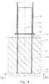
Fig. 4 shows another embodiment where the fastening element, at its lower portion, is equipped with drill bodies: -
Fig. 5 shows a section IV-IV infig. 4 ; and -
Fig. 6 shows in a larger scale a segment V-V infig. 5 of the lower portion pf the fastening element and a drill body. - On the drawings, the reference numeral 1 denotes a drill that by the help of a power drill 2 is under displacement into the
ground 4. Theground 4 may constitute for example rock, soil, or march, alternatively combination thereof. - The power drill 2 is typically aligned and is fixed to the
ground 4 or another suitable, not shown device. There after the power drill 2 that may be electrically or hydraulically driven, displaces the drill 1 into theground 4 while rotating the drill 1. Thus, a slit formedopening 6 is formed in theground 4. The drill 1 is then removed from the slit formed opening 6. - A
composite pole 8 that has been moved into the slit formedopening 6 is shown infig. 2 . Additional fixing of thecomposite pole 8 to theground 4 may be achieved by inserting grouting, fixing compound or other material (not shown) in between thecomposite pole 8 and theground 4. - In an embodiment of the invention, shown in
fig. 3 , a sleeve formedfastening element 10 is positioned in the slit formedopening 6. Additional fixing of thefixing element 10 to theground 4 may be carried out as described for thecomposite pole 8. Acomposite pole 8 that is conical inside is placed about thefastening element 10 that has a conicalupper portion 18 and a lowercylindrical end portion 12, and moved against the fastening element until abutment is established. - In some cases, as when the
ground 4 mainly constitutes suitable soil, thefixing element 10 may be forced into theground 4 by hammering. - In a further alternative embodiment as shown in
fig. 4 , thefastening element 10 is by itslower end portion 12 equipped withseveral drill elements 14. The section IV-IV infig 5 shows a possible distribution of thedrill elements 14 about thecentre axis 16 of thefastening element 10. The drill elements may be made from material from thefastening element 10 or constitute other materials that is fixed to thefastening element 10. - A
typical drill element 14 is shown infig. 6 where thedrill element 14 that constitutes hard metal, is braced to the in use lowercylindrical end portion 12 of thefixing element 10. - The
fixing element 10 shown infig. 4 is shown in two parts where in use anupper portion 18 that is fixed to thecomposite pole 8 is fixed to the in uselower portion 22 of thefixing element 10 by aflange connection 20. Thelower portion 22 is here drilled into theground 4. - It should be noted that the above-mentioned embodiments illustrate rather than limit the invention, and that those skilled in the art will be able to design many alternative embodiments without departing from the scope of the appended claims. In the claims, any reference signs placed between parentheses shall not be construed as limiting the claim. Use of the verb "comprise" and its conjugations does not exclude the presence of elements or steps other than those stated in a claim. The article "a" or "an" preceding an element does not exclude the presence of a plurality of such elements. The mere fact that certain measures are recited in mutually different dependent claims does not indicate that a combination of these measures cannot be used to advantage.
Claims (9)
- Fastening element (10) for fastening a hollow composite pole (8) for overhead power lines to the ground (4) at a location where a slit-formed opening (6) is present in the ground (4), wherein the fastening element (10) has a lower cylindrical end portion (12) that is configured for being positioned in the slit-formed opening (6) being circular, wherein the fastening element (10) has a conical upper portion (18), wherein, in operational use of the fastening element (10), a conical portion of the composite pole (8) is configured for moving over the conical upper portion (18) of the fastening element (10) until abutment with the fastening element (10) is established.
- The fastening element (10) according to claim 1, wherein the fastening element (10) at its lower end portion (12) is equipped with drill elements (14).
- The fastening element (10) according to claim 2, wherein the drill elements (14) comprise metal.
- The fastening element (10) according to claim 2, wherein the drill elements (14) comprise ceramic material.
- Method for fastening a hollow composite pole (8) for overhead power lines to the ground (4), wherein the method comprises:- making a circular slit-formed opening (6) in the ground (4);- inserting the fastening element (10) in accordance with claim 1 into the slit-formed opening (6), and- moving the composite pole (8) that is conical, over the fastening element (10) until abutment is established.
- The method according to claim 5, wherein the method comprises fixing the fastening element (10) to the ground (4).
- The method according to claim 5 or 6, wherein the method comprises making the slit-formed opening (6) by drilling into the ground (4).
- The method according to claim 5 or 6, wherein the method comprises making the slit-formed opening (6) by hammering the fastening element (10) into the ground (4).
- The method according to claim 5 to 7, wherein the method comprises providing the fastening element (10) in accordance with claim 2, and drilling the fastening element (10) into the ground.
Priority Applications (3)
| Application Number | Priority Date | Filing Date | Title |
|---|---|---|---|
| PL17725370T PL3417127T3 (en) | 2016-02-16 | 2017-02-16 | Apparatus and method for fastening a composite pole to the ground |
| HRP20201502TT HRP20201502T1 (en) | 2016-02-16 | 2017-02-16 | DEVICE AND PROCEDURE FOR FIXING A COMPOSITE PILLAR TO THE GROUND |
| SI201730460T SI3417127T1 (en) | 2016-02-16 | 2017-02-16 | Apparatus and method for fastening a composite pole to the ground |
Applications Claiming Priority (2)
| Application Number | Priority Date | Filing Date | Title |
|---|---|---|---|
| NO20160270A NO343861B1 (en) | 2016-02-16 | 2016-02-16 | Method of attaching a composite mast to the ground. |
| PCT/NO2017/050040 WO2017142419A1 (en) | 2016-02-16 | 2017-02-16 | Apparatus and method for fastening a composite pole to the ground |
Publications (2)
| Publication Number | Publication Date |
|---|---|
| EP3417127A1 EP3417127A1 (en) | 2018-12-26 |
| EP3417127B1 true EP3417127B1 (en) | 2020-07-22 |
Family
ID=58765887
Family Applications (1)
| Application Number | Title | Priority Date | Filing Date |
|---|---|---|---|
| EP17725370.5A Active EP3417127B1 (en) | 2016-02-16 | 2017-02-16 | Apparatus and method for fastening a composite pole to the ground |
Country Status (11)
| Country | Link |
|---|---|
| US (2) | US20210207335A1 (en) |
| EP (1) | EP3417127B1 (en) |
| AU (1) | AU2017219459B2 (en) |
| CA (1) | CA3014300A1 (en) |
| HR (1) | HRP20201502T1 (en) |
| HU (1) | HUE051287T2 (en) |
| NO (2) | NO343861B1 (en) |
| PL (1) | PL3417127T3 (en) |
| PT (1) | PT3417127T (en) |
| SI (1) | SI3417127T1 (en) |
| WO (1) | WO2017142419A1 (en) |
Families Citing this family (4)
| Publication number | Priority date | Publication date | Assignee | Title |
|---|---|---|---|---|
| NO344819B1 (en) | 2017-11-17 | 2020-05-04 | Comrod As | Method for creating a clearance for a mast element in a ground. |
| NO20171962A1 (en) * | 2017-12-08 | 2019-06-10 | Comrod As | Method for fixing a conical energy transportation mast to the ground. |
| NO20171964A1 (en) * | 2017-12-08 | 2019-06-10 | Comrod As | Energy transportation mast with different conicities. |
| NO346911B1 (en) * | 2021-01-11 | 2023-02-27 | Comrod As | Procedure for positioning a drilling machine when attaching a mast, typically an A-mast, in a terrain |
Family Cites Families (21)
| Publication number | Priority date | Publication date | Assignee | Title |
|---|---|---|---|---|
| US2023966A (en) * | 1935-06-01 | 1935-12-10 | Jesse A Montee | Method and means for sinking foundation columns |
| DE2708664A1 (en) * | 1976-03-01 | 1977-09-15 | Michel Leclerc | Overhead cable support pylon - has assembled repairable free part and ground sunken plinth component |
| DE3145882C2 (en) * | 1981-11-19 | 1985-05-02 | Eskilstuna Invest AB, Eskilstuna | Method of making a foundation for a mast or the like. |
| SE443015B (en) * | 1982-10-11 | 1986-02-10 | Sven Runo Vilhelm Gebelius | Pole shaped support component with foundation for its erection |
| FR2536780A1 (en) * | 1982-11-30 | 1984-06-01 | Petitjean Co Sa | Method for connecting the shaft of a pylon to a foundation and connecting element for the implementation of this method |
| US4671367A (en) * | 1985-12-05 | 1987-06-09 | Electric Power Research Institute, Inc. | Pole hole digger with percussive core drilling |
| US5697935A (en) * | 1995-09-12 | 1997-12-16 | Medex Marketing, Inc. | Device and method for removing fastening implements from bone |
| DE19702137A1 (en) * | 1997-01-22 | 1998-07-23 | Fundex N V | Earth displacement drill |
| DE29703858U1 (en) * | 1997-03-03 | 1997-07-24 | Jonas, Alfred, 21037 Hamburg | Pile stand |
| BE1011266A3 (en) * | 1997-07-08 | 1999-07-06 | Dresser Ind | Core. |
| CA2428549A1 (en) * | 2003-05-14 | 2004-11-14 | Resin Systems Inc. | Method of installing poles in a rock surface |
| AU2003903807A0 (en) * | 2003-07-23 | 2003-08-07 | Sidc Pty Ltd | Device for arranging a post in position |
| GB0516906D0 (en) * | 2005-08-18 | 2005-09-28 | Seacore Ltd | Methods and apparatus for the installation of foundation piles |
| US7484578B2 (en) * | 2006-01-17 | 2009-02-03 | U.S. Saws, Inc. | Hole coring system |
| DE202006015706U1 (en) * | 2006-10-11 | 2007-02-15 | Pfleiderer Europoles Gmbh & Co. Kg | Fixing device for a mast comprises an outer holder for inserting into the ground and an inner holder connected to the outer holder via a connecting unit to hold and fix a lower end of a mast |
| GB0624285D0 (en) * | 2006-12-05 | 2007-01-10 | Seacore Ltd | Methods and apparatus for the installation colums/piles |
| EP2463440A4 (en) * | 2009-08-07 | 2017-03-15 | Shindo Industry Co., Ltd | Separable lane-control bollard assembly |
| US20110047900A1 (en) * | 2009-08-24 | 2011-03-03 | UC Solutions, LLC | Modular Composite Utility Pole |
| EP2562348B1 (en) * | 2011-08-23 | 2017-10-04 | BAUER Maschinen GmbH | Underwater drilling assembly and method for producing a borehole |
| CN202500370U (en) * | 2011-11-08 | 2012-10-24 | 浙江新世管道股份有限公司 | Composite material telegraph pole |
| NL2015732B1 (en) * | 2015-11-05 | 2017-05-24 | Sapa Profiles Nl B V | Manufacturing method of a post comprising an isolated root section, and corresponding post. |
-
2016
- 2016-02-16 NO NO20160270A patent/NO343861B1/en unknown
- 2016-08-29 NO NO20161370A patent/NO20161370A1/en not_active Application Discontinuation
-
2017
- 2017-02-16 PT PT177253705T patent/PT3417127T/en unknown
- 2017-02-16 WO PCT/NO2017/050040 patent/WO2017142419A1/en not_active Ceased
- 2017-02-16 HU HUE17725370A patent/HUE051287T2/en unknown
- 2017-02-16 US US15/998,896 patent/US20210207335A1/en not_active Abandoned
- 2017-02-16 PL PL17725370T patent/PL3417127T3/en unknown
- 2017-02-16 CA CA3014300A patent/CA3014300A1/en active Pending
- 2017-02-16 SI SI201730460T patent/SI3417127T1/en unknown
- 2017-02-16 HR HRP20201502TT patent/HRP20201502T1/en unknown
- 2017-02-16 AU AU2017219459A patent/AU2017219459B2/en active Active
- 2017-02-16 EP EP17725370.5A patent/EP3417127B1/en active Active
-
2022
- 2022-01-07 US US17/571,057 patent/US20220127812A1/en not_active Abandoned
Non-Patent Citations (1)
| Title |
|---|
| None * |
Also Published As
| Publication number | Publication date |
|---|---|
| US20220127812A1 (en) | 2022-04-28 |
| HRP20201502T1 (en) | 2020-12-25 |
| NO20160270A1 (en) | 2017-08-17 |
| WO2017142419A1 (en) | 2017-08-24 |
| NO20161370A1 (en) | 2017-08-17 |
| US20210207335A1 (en) | 2021-07-08 |
| CA3014300A1 (en) | 2017-08-24 |
| AU2017219459A1 (en) | 2018-09-20 |
| NZ745302A (en) | 2021-11-26 |
| PL3417127T3 (en) | 2020-11-16 |
| AU2017219459B2 (en) | 2019-04-11 |
| EP3417127A1 (en) | 2018-12-26 |
| SI3417127T1 (en) | 2020-11-30 |
| HUE051287T2 (en) | 2021-03-01 |
| PT3417127T (en) | 2020-10-22 |
| NO343861B1 (en) | 2019-06-24 |
Similar Documents
| Publication | Publication Date | Title |
|---|---|---|
| US20220127812A1 (en) | Apparatus and method for fastening a composite pole to the ground | |
| EP3827130B1 (en) | Pile installation system | |
| CN104131822B (en) | Anti-pre-buried structure and the built-in process thereof of hanging of a kind of shield tunnel China's shield groove | |
| US9469959B2 (en) | Full displacement pile tip and method for use | |
| CN106812530B (en) | Use the method for construction of protrusion fashioned iron supporting material and the steel pipe multistage tunnel of nose girder | |
| JP2009046832A (en) | Pile device for foundation, vertical connecting means for use in it, and method for driving and installing foundation pile | |
| JP6424061B2 (en) | Foundation pile and its installation method | |
| US20080253830A1 (en) | Method of Installing Anchor Bolt, Method of Drilling Anchor Bolt Hole, and Drilling Device | |
| NZ745302B2 (en) | Apparatus and method for fastening a composite pole to the ground | |
| JP2015074881A (en) | Foundation pile construction method and foundation pile | |
| KR101376497B1 (en) | Connection tool for pretentioned spun high-strength concrete pile | |
| KR101847906B1 (en) | Simultaneous penetration type composite casing for pile and cast in place pile construction method using the same | |
| KR101656696B1 (en) | Apparatus for dismantling wire for pile lifting and pile construction method using the same | |
| JP2015063878A (en) | Method of constructing steel pipe pile and steel pipe pile | |
| JP6389681B2 (en) | Ground improvement method in front of face in tunnel excavation work. | |
| EP3710640B1 (en) | Method for generating a freeroom for a mast element | |
| US8734075B1 (en) | Sheared pole butt removal tool | |
| KR20160132343A (en) | Micro pile and construction method therefor | |
| AU2007100990A4 (en) | Pile construction | |
| CN112982513B (en) | Sensor mounting assembly and method for cast-in-place plain concrete piles in composite foundations | |
| KR20190108780A (en) | Sd nailing method | |
| EP2813623A1 (en) | Anchor device and drilling assembly incorporating such anchor member | |
| JP2013204416A (en) | Trench digging bit | |
| JP3204371U (en) | Pile foundation | |
| NO20171962A1 (en) | Method for fixing a conical energy transportation mast to the ground. |
Legal Events
| Date | Code | Title | Description |
|---|---|---|---|
| STAA | Information on the status of an ep patent application or granted ep patent |
Free format text: STATUS: UNKNOWN |
|
| STAA | Information on the status of an ep patent application or granted ep patent |
Free format text: STATUS: THE INTERNATIONAL PUBLICATION HAS BEEN MADE |
|
| PUAI | Public reference made under article 153(3) epc to a published international application that has entered the european phase |
Free format text: ORIGINAL CODE: 0009012 |
|
| STAA | Information on the status of an ep patent application or granted ep patent |
Free format text: STATUS: REQUEST FOR EXAMINATION WAS MADE |
|
| 17P | Request for examination filed |
Effective date: 20180814 |
|
| AK | Designated contracting states |
Kind code of ref document: A1 Designated state(s): AL AT BE BG CH CY CZ DE DK EE ES FI FR GB GR HR HU IE IS IT LI LT LU LV MC MK MT NL NO PL PT RO RS SE SI SK SM TR |
|
| AX | Request for extension of the european patent |
Extension state: BA ME |
|
| DAV | Request for validation of the european patent (deleted) | ||
| DAX | Request for extension of the european patent (deleted) | ||
| STAA | Information on the status of an ep patent application or granted ep patent |
Free format text: STATUS: EXAMINATION IS IN PROGRESS |
|
| 17Q | First examination report despatched |
Effective date: 20200120 |
|
| GRAP | Despatch of communication of intention to grant a patent |
Free format text: ORIGINAL CODE: EPIDOSNIGR1 |
|
| STAA | Information on the status of an ep patent application or granted ep patent |
Free format text: STATUS: GRANT OF PATENT IS INTENDED |
|
| INTG | Intention to grant announced |
Effective date: 20200327 |
|
| GRAS | Grant fee paid |
Free format text: ORIGINAL CODE: EPIDOSNIGR3 |
|
| GRAA | (expected) grant |
Free format text: ORIGINAL CODE: 0009210 |
|
| STAA | Information on the status of an ep patent application or granted ep patent |
Free format text: STATUS: THE PATENT HAS BEEN GRANTED |
|
| AK | Designated contracting states |
Kind code of ref document: B1 Designated state(s): AL AT BE BG CH CY CZ DE DK EE ES FI FR GB GR HR HU IE IS IT LI LT LU LV MC MK MT NL NO PL PT RO RS SE SI SK SM TR |
|
| REG | Reference to a national code |
Ref country code: GB Ref legal event code: FG4D |
|
| REG | Reference to a national code |
Ref country code: CH Ref legal event code: EP |
|
| REG | Reference to a national code |
Ref country code: DE Ref legal event code: R096 Ref document number: 602017020184 Country of ref document: DE |
|
| REG | Reference to a national code |
Ref country code: AT Ref legal event code: REF Ref document number: 1293517 Country of ref document: AT Kind code of ref document: T Effective date: 20200815 |
|
| REG | Reference to a national code |
Ref country code: IE Ref legal event code: FG4D |
|
| REG | Reference to a national code |
Ref country code: CH Ref legal event code: NV Representative=s name: ISLER AND PEDRAZZINI AG, CH |
|
| REG | Reference to a national code |
Ref country code: SE Ref legal event code: TRGR |
|
| REG | Reference to a national code |
Ref country code: HR Ref legal event code: TUEP Ref document number: P20201502 Country of ref document: HR |
|
| REG | Reference to a national code |
Ref country code: FI Ref legal event code: FGE |
|
| REG | Reference to a national code |
Ref country code: PT Ref legal event code: SC4A Ref document number: 3417127 Country of ref document: PT Date of ref document: 20201022 Kind code of ref document: T Free format text: AVAILABILITY OF NATIONAL TRANSLATION Effective date: 20201016 |
|
| REG | Reference to a national code |
Ref country code: SK Ref legal event code: T3 Ref document number: E 35548 Country of ref document: SK |
|
| REG | Reference to a national code |
Ref country code: LT Ref legal event code: MG4D |
|
| REG | Reference to a national code |
Ref country code: HR Ref legal event code: ODRP Ref document number: P20201502 Country of ref document: HR Payment date: 20200922 Year of fee payment: 5 |
|
| REG | Reference to a national code |
Ref country code: HR Ref legal event code: T1PR Ref document number: P20201502 Country of ref document: HR |
|
| PG25 | Lapsed in a contracting state [announced via postgrant information from national office to epo] |
Ref country code: NO Free format text: LAPSE BECAUSE OF FAILURE TO SUBMIT A TRANSLATION OF THE DESCRIPTION OR TO PAY THE FEE WITHIN THE PRESCRIBED TIME-LIMIT Effective date: 20201022 Ref country code: GR Free format text: LAPSE BECAUSE OF FAILURE TO SUBMIT A TRANSLATION OF THE DESCRIPTION OR TO PAY THE FEE WITHIN THE PRESCRIBED TIME-LIMIT Effective date: 20201023 Ref country code: BG Free format text: LAPSE BECAUSE OF FAILURE TO SUBMIT A TRANSLATION OF THE DESCRIPTION OR TO PAY THE FEE WITHIN THE PRESCRIBED TIME-LIMIT Effective date: 20201022 Ref country code: LT Free format text: LAPSE BECAUSE OF FAILURE TO SUBMIT A TRANSLATION OF THE DESCRIPTION OR TO PAY THE FEE WITHIN THE PRESCRIBED TIME-LIMIT Effective date: 20200722 Ref country code: ES Free format text: LAPSE BECAUSE OF FAILURE TO SUBMIT A TRANSLATION OF THE DESCRIPTION OR TO PAY THE FEE WITHIN THE PRESCRIBED TIME-LIMIT Effective date: 20200722 |
|
| REG | Reference to a national code |
Ref country code: AT Ref legal event code: UEP Ref document number: 1293517 Country of ref document: AT Kind code of ref document: T Effective date: 20200722 |
|
| PG25 | Lapsed in a contracting state [announced via postgrant information from national office to epo] |
Ref country code: RS Free format text: LAPSE BECAUSE OF FAILURE TO SUBMIT A TRANSLATION OF THE DESCRIPTION OR TO PAY THE FEE WITHIN THE PRESCRIBED TIME-LIMIT Effective date: 20200722 Ref country code: LV Free format text: LAPSE BECAUSE OF FAILURE TO SUBMIT A TRANSLATION OF THE DESCRIPTION OR TO PAY THE FEE WITHIN THE PRESCRIBED TIME-LIMIT Effective date: 20200722 |
|
| REG | Reference to a national code |
Ref country code: HU Ref legal event code: AG4A Ref document number: E051287 Country of ref document: HU |
|
| PG25 | Lapsed in a contracting state [announced via postgrant information from national office to epo] |
Ref country code: NL Free format text: LAPSE BECAUSE OF FAILURE TO SUBMIT A TRANSLATION OF THE DESCRIPTION OR TO PAY THE FEE WITHIN THE PRESCRIBED TIME-LIMIT Effective date: 20200722 |
|
| REG | Reference to a national code |
Ref country code: DE Ref legal event code: R097 Ref document number: 602017020184 Country of ref document: DE |
|
| PG25 | Lapsed in a contracting state [announced via postgrant information from national office to epo] |
Ref country code: SM Free format text: LAPSE BECAUSE OF FAILURE TO SUBMIT A TRANSLATION OF THE DESCRIPTION OR TO PAY THE FEE WITHIN THE PRESCRIBED TIME-LIMIT Effective date: 20200722 Ref country code: EE Free format text: LAPSE BECAUSE OF FAILURE TO SUBMIT A TRANSLATION OF THE DESCRIPTION OR TO PAY THE FEE WITHIN THE PRESCRIBED TIME-LIMIT Effective date: 20200722 Ref country code: RO Free format text: LAPSE BECAUSE OF FAILURE TO SUBMIT A TRANSLATION OF THE DESCRIPTION OR TO PAY THE FEE WITHIN THE PRESCRIBED TIME-LIMIT Effective date: 20200722 Ref country code: DK Free format text: LAPSE BECAUSE OF FAILURE TO SUBMIT A TRANSLATION OF THE DESCRIPTION OR TO PAY THE FEE WITHIN THE PRESCRIBED TIME-LIMIT Effective date: 20200722 |
|
| PLBE | No opposition filed within time limit |
Free format text: ORIGINAL CODE: 0009261 |
|
| STAA | Information on the status of an ep patent application or granted ep patent |
Free format text: STATUS: NO OPPOSITION FILED WITHIN TIME LIMIT |
|
| PG25 | Lapsed in a contracting state [announced via postgrant information from national office to epo] |
Ref country code: AL Free format text: LAPSE BECAUSE OF FAILURE TO SUBMIT A TRANSLATION OF THE DESCRIPTION OR TO PAY THE FEE WITHIN THE PRESCRIBED TIME-LIMIT Effective date: 20200722 |
|
| 26N | No opposition filed |
Effective date: 20210423 |
|
| PG25 | Lapsed in a contracting state [announced via postgrant information from national office to epo] |
Ref country code: MC Free format text: LAPSE BECAUSE OF FAILURE TO SUBMIT A TRANSLATION OF THE DESCRIPTION OR TO PAY THE FEE WITHIN THE PRESCRIBED TIME-LIMIT Effective date: 20200722 |
|
| REG | Reference to a national code |
Ref country code: NL Ref legal event code: MP Effective date: 20200722 |
|
| REG | Reference to a national code |
Ref country code: BE Ref legal event code: MM Effective date: 20210228 |
|
| PG25 | Lapsed in a contracting state [announced via postgrant information from national office to epo] |
Ref country code: LU Free format text: LAPSE BECAUSE OF NON-PAYMENT OF DUE FEES Effective date: 20210216 |
|
| PG25 | Lapsed in a contracting state [announced via postgrant information from national office to epo] |
Ref country code: IE Free format text: LAPSE BECAUSE OF NON-PAYMENT OF DUE FEES Effective date: 20210216 |
|
| REG | Reference to a national code |
Ref country code: HR Ref legal event code: ODRP Ref document number: P20201502 Country of ref document: HR Payment date: 20220117 Year of fee payment: 6 |
|
| PG25 | Lapsed in a contracting state [announced via postgrant information from national office to epo] |
Ref country code: BE Free format text: LAPSE BECAUSE OF NON-PAYMENT OF DUE FEES Effective date: 20210228 |
|
| REG | Reference to a national code |
Ref country code: HR Ref legal event code: ODRP Ref document number: P20201502 Country of ref document: HR Payment date: 20230104 Year of fee payment: 7 |
|
| P01 | Opt-out of the competence of the unified patent court (upc) registered |
Effective date: 20230524 |
|
| PG25 | Lapsed in a contracting state [announced via postgrant information from national office to epo] |
Ref country code: CY Free format text: LAPSE BECAUSE OF FAILURE TO SUBMIT A TRANSLATION OF THE DESCRIPTION OR TO PAY THE FEE WITHIN THE PRESCRIBED TIME-LIMIT Effective date: 20200722 |
|
| REG | Reference to a national code |
Ref country code: HR Ref legal event code: ODRP Ref document number: P20201502 Country of ref document: HR Payment date: 20240124 Year of fee payment: 8 |
|
| PG25 | Lapsed in a contracting state [announced via postgrant information from national office to epo] |
Ref country code: MK Free format text: LAPSE BECAUSE OF FAILURE TO SUBMIT A TRANSLATION OF THE DESCRIPTION OR TO PAY THE FEE WITHIN THE PRESCRIBED TIME-LIMIT Effective date: 20200722 |
|
| PG25 | Lapsed in a contracting state [announced via postgrant information from national office to epo] |
Ref country code: MT Free format text: LAPSE BECAUSE OF FAILURE TO SUBMIT A TRANSLATION OF THE DESCRIPTION OR TO PAY THE FEE WITHIN THE PRESCRIBED TIME-LIMIT Effective date: 20200722 |
|
| REG | Reference to a national code |
Ref country code: HR Ref legal event code: ODRP Ref document number: P20201502 Country of ref document: HR Payment date: 20250123 Year of fee payment: 9 |
|
| REG | Reference to a national code |
Ref country code: HR Ref legal event code: ODRP Ref document number: P20201502 Country of ref document: HR Payment date: 20260120 Year of fee payment: 10 |
|
| REG | Reference to a national code |
Ref country code: CH Ref legal event code: U11 Free format text: ST27 STATUS EVENT CODE: U-0-0-U10-U11 (AS PROVIDED BY THE NATIONAL OFFICE) Effective date: 20260301 |
|
| PGFP | Annual fee paid to national office [announced via postgrant information from national office to epo] |
Ref country code: HU Payment date: 20260127 Year of fee payment: 10 |
|
| PGFP | Annual fee paid to national office [announced via postgrant information from national office to epo] |
Ref country code: SE Payment date: 20260213 Year of fee payment: 10 |
|
| PGFP | Annual fee paid to national office [announced via postgrant information from national office to epo] |
Ref country code: GB Payment date: 20260210 Year of fee payment: 10 |
|
| PGFP | Annual fee paid to national office [announced via postgrant information from national office to epo] |
Ref country code: DE Payment date: 20260213 Year of fee payment: 10 |
|
| PGFP | Annual fee paid to national office [announced via postgrant information from national office to epo] |
Ref country code: AT Payment date: 20260213 Year of fee payment: 10 Ref country code: HR Payment date: 20260120 Year of fee payment: 10 |
|
| PGFP | Annual fee paid to national office [announced via postgrant information from national office to epo] |
Ref country code: FI Payment date: 20260224 Year of fee payment: 10 Ref country code: IT Payment date: 20260210 Year of fee payment: 10 |
|
| PGFP | Annual fee paid to national office [announced via postgrant information from national office to epo] |
Ref country code: IS Payment date: 20260210 Year of fee payment: 10 Ref country code: FR Payment date: 20260212 Year of fee payment: 10 |
|
| PGFP | Annual fee paid to national office [announced via postgrant information from national office to epo] |
Ref country code: TR Payment date: 20260120 Year of fee payment: 10 |
|
| PGFP | Annual fee paid to national office [announced via postgrant information from national office to epo] |
Ref country code: CH Payment date: 20260301 Year of fee payment: 10 Ref country code: CZ Payment date: 20260121 Year of fee payment: 10 Ref country code: PT Payment date: 20260203 Year of fee payment: 10 |
|
| PGFP | Annual fee paid to national office [announced via postgrant information from national office to epo] |
Ref country code: PL Payment date: 20260121 Year of fee payment: 10 |
|
| PGFP | Annual fee paid to national office [announced via postgrant information from national office to epo] |
Ref country code: SK Payment date: 20260120 Year of fee payment: 10 |
|
| PGFP | Annual fee paid to national office [announced via postgrant information from national office to epo] |
Ref country code: SI Payment date: 20260120 Year of fee payment: 10 |