EP3416846B1 - Industrial hydraulic power take off - Google Patents
Industrial hydraulic power take off Download PDFInfo
- Publication number
- EP3416846B1 EP3416846B1 EP17753735.4A EP17753735A EP3416846B1 EP 3416846 B1 EP3416846 B1 EP 3416846B1 EP 17753735 A EP17753735 A EP 17753735A EP 3416846 B1 EP3416846 B1 EP 3416846B1
- Authority
- EP
- European Patent Office
- Prior art keywords
- housing
- oil
- hydraulic
- tower
- pto
- Prior art date
- Legal status (The legal status is an assumption and is not a legal conclusion. Google has not performed a legal analysis and makes no representation as to the accuracy of the status listed.)
- Not-in-force
Links
Images






Classifications
-
- F—MECHANICAL ENGINEERING; LIGHTING; HEATING; WEAPONS; BLASTING
- F16—ENGINEERING ELEMENTS AND UNITS; GENERAL MEASURES FOR PRODUCING AND MAINTAINING EFFECTIVE FUNCTIONING OF MACHINES OR INSTALLATIONS; THERMAL INSULATION IN GENERAL
- F16D—COUPLINGS FOR TRANSMITTING ROTATION; CLUTCHES; BRAKES
- F16D25/00—Fluid-actuated clutches
- F16D25/12—Details not specific to one of the before-mentioned types
- F16D25/123—Details not specific to one of the before-mentioned types in view of cooling and lubrication
-
- B—PERFORMING OPERATIONS; TRANSPORTING
- B60—VEHICLES IN GENERAL
- B60T—VEHICLE BRAKE CONTROL SYSTEMS OR PARTS THEREOF; BRAKE CONTROL SYSTEMS OR PARTS THEREOF, IN GENERAL; ARRANGEMENT OF BRAKING ELEMENTS ON VEHICLES IN GENERAL; PORTABLE DEVICES FOR PREVENTING UNWANTED MOVEMENT OF VEHICLES; VEHICLE MODIFICATIONS TO FACILITATE COOLING OF BRAKES
- B60T1/00—Arrangements of braking elements, i.e. of those parts where braking effect occurs specially for vehicles
- B60T1/02—Arrangements of braking elements, i.e. of those parts where braking effect occurs specially for vehicles acting by retarding wheels
- B60T1/06—Arrangements of braking elements, i.e. of those parts where braking effect occurs specially for vehicles acting by retarding wheels acting otherwise than on tread, e.g. employing rim, drum, disc, or transmission or on double wheels
- B60T1/062—Arrangements of braking elements, i.e. of those parts where braking effect occurs specially for vehicles acting by retarding wheels acting otherwise than on tread, e.g. employing rim, drum, disc, or transmission or on double wheels acting on transmission parts
-
- B—PERFORMING OPERATIONS; TRANSPORTING
- B60—VEHICLES IN GENERAL
- B60K—ARRANGEMENT OR MOUNTING OF PROPULSION UNITS OR OF TRANSMISSIONS IN VEHICLES; ARRANGEMENT OR MOUNTING OF PLURAL DIVERSE PRIME-MOVERS IN VEHICLES; AUXILIARY DRIVES FOR VEHICLES; INSTRUMENTATION OR DASHBOARDS FOR VEHICLES; ARRANGEMENTS IN CONNECTION WITH COOLING, AIR INTAKE, GAS EXHAUST OR FUEL SUPPLY OF PROPULSION UNITS IN VEHICLES
- B60K17/00—Arrangement or mounting of transmissions in vehicles
- B60K17/02—Arrangement or mounting of transmissions in vehicles characterised by arrangement, location, or kind of clutch
-
- B—PERFORMING OPERATIONS; TRANSPORTING
- B60—VEHICLES IN GENERAL
- B60K—ARRANGEMENT OR MOUNTING OF PROPULSION UNITS OR OF TRANSMISSIONS IN VEHICLES; ARRANGEMENT OR MOUNTING OF PLURAL DIVERSE PRIME-MOVERS IN VEHICLES; AUXILIARY DRIVES FOR VEHICLES; INSTRUMENTATION OR DASHBOARDS FOR VEHICLES; ARRANGEMENTS IN CONNECTION WITH COOLING, AIR INTAKE, GAS EXHAUST OR FUEL SUPPLY OF PROPULSION UNITS IN VEHICLES
- B60K17/00—Arrangement or mounting of transmissions in vehicles
- B60K17/28—Arrangement or mounting of transmissions in vehicles characterised by arrangement, location, or type of power take-off
-
- B—PERFORMING OPERATIONS; TRANSPORTING
- B60—VEHICLES IN GENERAL
- B60K—ARRANGEMENT OR MOUNTING OF PROPULSION UNITS OR OF TRANSMISSIONS IN VEHICLES; ARRANGEMENT OR MOUNTING OF PLURAL DIVERSE PRIME-MOVERS IN VEHICLES; AUXILIARY DRIVES FOR VEHICLES; INSTRUMENTATION OR DASHBOARDS FOR VEHICLES; ARRANGEMENTS IN CONNECTION WITH COOLING, AIR INTAKE, GAS EXHAUST OR FUEL SUPPLY OF PROPULSION UNITS IN VEHICLES
- B60K25/00—Auxiliary drives
-
- F—MECHANICAL ENGINEERING; LIGHTING; HEATING; WEAPONS; BLASTING
- F16—ENGINEERING ELEMENTS AND UNITS; GENERAL MEASURES FOR PRODUCING AND MAINTAINING EFFECTIVE FUNCTIONING OF MACHINES OR INSTALLATIONS; THERMAL INSULATION IN GENERAL
- F16D—COUPLINGS FOR TRANSMITTING ROTATION; CLUTCHES; BRAKES
- F16D13/00—Friction clutches
- F16D13/22—Friction clutches with axially-movable clutching members
- F16D13/38—Friction clutches with axially-movable clutching members with flat clutching surfaces, e.g. discs
- F16D13/52—Clutches with multiple lamellae ; Clutches in which three or more axially moveable members are fixed alternately to the shafts to be coupled and are pressed from one side towards an axially-located member
-
- F—MECHANICAL ENGINEERING; LIGHTING; HEATING; WEAPONS; BLASTING
- F16—ENGINEERING ELEMENTS AND UNITS; GENERAL MEASURES FOR PRODUCING AND MAINTAINING EFFECTIVE FUNCTIONING OF MACHINES OR INSTALLATIONS; THERMAL INSULATION IN GENERAL
- F16D—COUPLINGS FOR TRANSMITTING ROTATION; CLUTCHES; BRAKES
- F16D67/00—Combinations of couplings and brakes; Combinations of clutches and brakes
- F16D67/02—Clutch-brake combinations
- F16D67/04—Clutch-brake combinations fluid actuated
-
- B—PERFORMING OPERATIONS; TRANSPORTING
- B60—VEHICLES IN GENERAL
- B60K—ARRANGEMENT OR MOUNTING OF PROPULSION UNITS OR OF TRANSMISSIONS IN VEHICLES; ARRANGEMENT OR MOUNTING OF PLURAL DIVERSE PRIME-MOVERS IN VEHICLES; AUXILIARY DRIVES FOR VEHICLES; INSTRUMENTATION OR DASHBOARDS FOR VEHICLES; ARRANGEMENTS IN CONNECTION WITH COOLING, AIR INTAKE, GAS EXHAUST OR FUEL SUPPLY OF PROPULSION UNITS IN VEHICLES
- B60K25/00—Auxiliary drives
- B60K25/02—Auxiliary drives directly from an engine shaft
- B60K2025/022—Auxiliary drives directly from an engine shaft by a mechanical transmission
-
- B—PERFORMING OPERATIONS; TRANSPORTING
- B60—VEHICLES IN GENERAL
- B60K—ARRANGEMENT OR MOUNTING OF PROPULSION UNITS OR OF TRANSMISSIONS IN VEHICLES; ARRANGEMENT OR MOUNTING OF PLURAL DIVERSE PRIME-MOVERS IN VEHICLES; AUXILIARY DRIVES FOR VEHICLES; INSTRUMENTATION OR DASHBOARDS FOR VEHICLES; ARRANGEMENTS IN CONNECTION WITH COOLING, AIR INTAKE, GAS EXHAUST OR FUEL SUPPLY OF PROPULSION UNITS IN VEHICLES
- B60K25/00—Auxiliary drives
- B60K25/02—Auxiliary drives directly from an engine shaft
- B60K2025/026—Auxiliary drives directly from an engine shaft by a hydraulic transmission
-
- B—PERFORMING OPERATIONS; TRANSPORTING
- B60—VEHICLES IN GENERAL
- B60K—ARRANGEMENT OR MOUNTING OF PROPULSION UNITS OR OF TRANSMISSIONS IN VEHICLES; ARRANGEMENT OR MOUNTING OF PLURAL DIVERSE PRIME-MOVERS IN VEHICLES; AUXILIARY DRIVES FOR VEHICLES; INSTRUMENTATION OR DASHBOARDS FOR VEHICLES; ARRANGEMENTS IN CONNECTION WITH COOLING, AIR INTAKE, GAS EXHAUST OR FUEL SUPPLY OF PROPULSION UNITS IN VEHICLES
- B60K25/00—Auxiliary drives
- B60K25/02—Auxiliary drives directly from an engine shaft
-
- F—MECHANICAL ENGINEERING; LIGHTING; HEATING; WEAPONS; BLASTING
- F16—ENGINEERING ELEMENTS AND UNITS; GENERAL MEASURES FOR PRODUCING AND MAINTAINING EFFECTIVE FUNCTIONING OF MACHINES OR INSTALLATIONS; THERMAL INSULATION IN GENERAL
- F16D—COUPLINGS FOR TRANSMITTING ROTATION; CLUTCHES; BRAKES
- F16D2300/00—Special features for couplings or clutches
- F16D2300/06—Lubrication details not provided for in group F16D13/74
-
- F—MECHANICAL ENGINEERING; LIGHTING; HEATING; WEAPONS; BLASTING
- F16—ENGINEERING ELEMENTS AND UNITS; GENERAL MEASURES FOR PRODUCING AND MAINTAINING EFFECTIVE FUNCTIONING OF MACHINES OR INSTALLATIONS; THERMAL INSULATION IN GENERAL
- F16D—COUPLINGS FOR TRANSMITTING ROTATION; CLUTCHES; BRAKES
- F16D2300/00—Special features for couplings or clutches
- F16D2300/26—Cover or bell housings; Details or arrangements thereof
Definitions
- the preferred embodiments are directed to an industrial hydraulic power take-off unit (PTO) and more particularly, to a hydraulic PTO which does not require a clutch adjustment and which allows for maximum side load capability.
- PTO industrial hydraulic power take-off unit
- the invention can be used wherever a disconnect is required between the driven equipment and the prime mover.
- the inventive PTO may be used in any stationary or mobile applications such as within the wood chipping industry where wood chippers are configured to chip whole trees of a large diameter, or perhaps on an agricultural tractor, dump truck, boom, winch, or the like.
- Hydraulic PTO units have been known to be used in a variety of applications. Historically, a single PTO unit was developed in such a way that it could be used in a number of applications with a number of different power sources. For example, one PTO design may be used to power a generator, a winch, a centrifugal pump, a blower, a compressor, and a fan. Each one of these applications may require a unique power source, such as a large diesel engine, a small gas engine, or anything in between or similar. Each unique application may also have a unique housing for the engine and PTO. For example, a generator will have a unique housing and footprint compared to that of a centrifugal pump.
- the PTO unit When configuring the PTO for use with each individual application, proper care must be taken in order to ensure that lubricating oil within the unit sufficiently flows through the necessary areas of the assembly. Due to the unique configuration of each engine and machine housing, the PTO unit is typically installed in various positions/angles, depending on the application. As proper flow of lubricating oil is critical to PTO longevity and performance, ancillary hydraulic lines, pumps, and reservoirs are commonly installed to ensure the lubricating oil reaches all the necessary components and properly drains. Known PTO units therefore require customization for each application.
- US 2007/0163253 A1 shows a hydrostatic transaxle for a vehicle with a PTO included.
- a vehicle PTO driveline in which a PTO input shaft drives a PTO wet clutch which when engaged drives a PTO output shaft.
- Some PTOs have tower sections with tower drive ears or pads for driving accessories that extend outwardly from the main PTO housings that hold clutches and brakes of the PTOs.
- Different applications require different tower orientations relative to the main PTO housings, which can present challenges for the oil flow path routing for shared lubrication of the tower sections and main PTO housings. Accordingly, gravity could not be relied on to properly drain the oil to a wet sump, since each installation of the PTO most often requires a unique orientation.
- different tower orientations require different oil plumbing kits, including changing a current tower orientation to a different tower orientation if a machine gets reconfigured.
- Oil plumbing kits or adding supplemental hydraulic lines, pumps, and reservoirs to the PTO adds significant expense to the hardware as well as significant expense to the installation of the PTO.
- a PTO lubrication system that uses gravity as the draining force of the lubrication system regardless of the orientation of the PTO.
- the preferred embodiments overcome the above-noted drawbacks by providing a heavy-duty industrial PTO that can be implemented in a variety of systems with gravity-assisted hydraulic oil drains.
- the prime mover for the inventive PTO can ideally be driven up to at least 1,243 horsepower (hp) at 1,800 revolutions per minute (rpm).
- the PTO is designed to withstand such demanding work conditions.
- the inventive PTO is ideal for a wide range of applications such as driving pumps, grinders, crushers, dredgers, chippers, shredders, heavy-duty drills, and more.
- the inventive PTO has a modular design allowing suitability for both side-load "P" and in-line “I” applications with the simple change of bearing carriers.
- An advanced control system allowing for smooth engagement of the driven equipment, may also be utilized.
- Another feature is a pair of auxiliary drive pump pads with approximately 400 hp maximum capacity per tower, or about 550 hp maximum for both towers.
- the pump towers are rotatable by approximately 0°, 45°, and 90°, either clockwise or counter-clockwise, to allow for clearance in installation.
- the pump tower(s) preferably have at least two pump pads each.
- a wide variety of pump pads may be suitable for this purpose, such as SAE "A”, SAE "B”, SAE “C”, SAE “D”, SAE "E”, or similar.
- the PTO may utilize an input housing similar to SAE #0, SAE #1, SAE #2, SAE #3, SAE #4, SAE #5, SAE #6, or any other preferably SAE size to prevent burnup in performance applications.
- the PTO may also utilize SAE 460, or SAE 355 input coupling or alternatively a flexible coupling.
- the pump tower(s) may include an optional speed increase to handle the stress of higher engine speeds.
- the inventive PTO also optionally features an integrated hydraulic sump. Unlike a separate, externally mounted sump/reservoir, the integrated sump saves space and reduces installation cost. An innovative design, it allows for the installation of the standard charge/lube pump on a separate pad, freeing up all four auxiliary pads for customer use.
- SAHR spring applied, hydraulically released brake
- An innovative, high-capacity brake with control logic is offered as an option. It slows the output when driving large masses in a shorter amount of time than conventional systems.
- the inventive PTO also utilizes an oil-filled, multiple disc, hydraulically actuated self-adjusting clutch.
- the inventive PTO has therefore been developed with a number of unique features that offer reliability, productivity, and power, including: integral mechanical brake release, optional integrated reservoir, and optional hydraulic gear pump.
- the inventive PTO may therefore be used in a wide range of heavy-duty applications including crushers, grinders, mulchers, dredgers, heavy-duty drills, and the like.
- the industrial hydraulic power take-off "PTO” includes a housing mounted between a prime mover and a piece of driven equipment.
- the housing includes a hydraulic section having a clutch housing with multiple passages directing oil throughout the PTO.
- the clutch is a hydraulically actuated and self-adjusting clutch. Mechanical clutches tend to need adjusting of their actuating cable, whereas hydraulic clutches are usually self-adjusting.
- the self-adjusting clutch additionally allows for a high side-load capability.
- a tower housing may also have multiple passages directing oil through the tower housing.
- the tower housing is configured to connect to the clutch housing in multiple angularly indexed positions with respect to the clutch housing.
- An embodiment may utilize an actuator to switch, move, or adjust a secondary mechanism.
- the actuator may be a remote actuator, switch-input actuator, or any known or contemplated actuator to supply remote, operator-induced, or automated actuation of a secondary mechanism without departing from the spirit of the invention.
- Pilot bearings wear down, and a worn down or damaged pilot bearing creates high volume noises and may cause a transmission to jump out of gear as well as creates the potential for catastrophic transmission failure.
- the inventive PTO circumvents these potential problems by not utilizing a pilot bearing.
- a multi-position adapter is arranged between the tower and clutch housings.
- the multi-position adapter includes spaced-apart openings that align with various passages of the hydraulic and tower housings.
- the multi-position adapter defines corresponding oil flow paths between respective ones of the passages of the hydraulic and tower housing and blocks flow through the remainder of the passages of the hydraulic and tower housings. This allows for the PTO to operate with a gravity drained hydraulic oil system with a common sump at the lowest point of the clutch housing, despite the indexed orientation of the adjustable tower housing.
- a hydraulic PTO (power take-off) 5 with a multi-position forced lubrication system 10 and including a sump 80 is shown implemented in an industrial drive 15.
- the industrial drive 15 delivers power from a prime mover 20, which may be a high-power internal combustion engine, to a piece of industrial equipment 25.
- Industrial drive 15 is shown here configured for side-load power delivery and includes a pulley arrangement 30 and belt(s) 35 that transmit power from hydraulic PTO 5 to a driven component(s) of the industrial equipment 25.
- the drive need not be limited to a pulley arrangement 30 and belt(s) 35 as shown, but may be any known drive such as direct drive, chain drive, or the like.
- the industrial equipment 25 may be, for example, a whole-tree chipper or other industrial wood chipper, a heavy-duty pump system, a grinder, a crusher, a dredge, a shredder, or a heavy-duty drill system that has a large rotating mass such as a rotatable component(s) 40 that establishes large inertial loads while rotating.
- Hydraulic oil is circulated throughout the hydraulic PTO 5 to lubricate bearings and other components and to hydraulically actuate various components such as clutch and brake assemblies that transmit power from the prime mover 20 to the power equipment 25.
- the oil is gravity drained to a common integrated sump at the bottom of the hydraulic PTO 5, as explained in greater detail herein.
- the body of the hydraulic PTO 5 is made up of a tower housing 70 and a main PTO housing or clutch housing 50 that houses a clutch and brake assembly.
- the tower housing 70 can be mounted to the prime mover 20 ( FIG. 1 ) in a plurality of ways by clocking, or rotating, the clutch housing 50 with respect to the tower housing 70.
- a series of fasteners 52 may be removed to allow for the clocking action and reattached once the tower housing 70 is in a suitable location for proper attachment to the prime mover 20.
- a pair of pump pads 75 is in a vertical orientation with the tower housing 70 affixed to the clutch housing 50 with fasteners 52.
- An additional feature shown is a vent line 88, which allows for pressure equalization of the various oil ports within the hydraulic PTO 5.
- hydraulic PTO 5 includes an input end 55 configured for attachment to a variety of different prime movers 20 ( FIG. 1 ) and an output end 60 configured to drive a plurality of devices with the output drive 34.
- the tower housing 70 and two pump pads 75 are arranged between the input end 55 and output end 60 of the hydraulic PTO 5.
- the pump pads 75 may be configured to drive a plurality of devices.
- the hydraulic PTO 5 may be attached to a prime mover 20, as shown, for example, in FIG. 1 , with a series of mounting holes 36 in a plurality of orientations. In any orientation, hydraulic oil flows within the hydraulic PTO 5 through a series of passages, as shown in FIGS. 3-5 .
- the hydraulic oil lubricates the internals of the hydraulic PTO 5 within both the tower housing 70 and the clutch housing 50 and is configured to operate with a gravity drain to a common sump 80.
- the sump 80 collects the hydraulic oil under the power of gravity and, as a result, is at the lowest point of the clutch housing 50. Once in the sump 80, the hydraulic oil can then be scavenged by a pump and recirculated throughout the hydraulic PTO 5 to lubricate the various internal parts.
- FIG. 3 shows a cross-sectional view along the section line A:A of FIG. 2 .
- a multi-position adapter 26, or baffle plate is placed between the tower housing 70 and the clutch housing 50.
- the multi-position adapter 26 includes a plurality of holes that accept fasteners 52 ( FIG. 2 ) to pass through and allow the tower housing 70 and clutch housing 50 to be mated together under clamping force of the fasteners 52.
- a main hydraulic oil supply passage 106 and a forced lube supply port 104 provide the initial hydraulic oil supply for the hydraulic PTO 5. As shown in FIG. 2 , the main oil supply passage 106 and the forced lube supply port 104 are both proximate the sump 80 on the clutch housing 50. For this reason, the main oil supply passage 106 and the forced lube supply port 104 require the assistance of gravity to ensure a continuous supply of hydraulic oil in the sump 80. As discussed above, the sump 80 on the clutch housing 50 is required to be mounted to the tower housing 70 in an orientation as shown in FIG. 2 to allow gravity to maintain the hydraulic oil level within the sump.
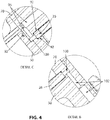
- FIG. 4 a detailed view of Details B and C of FIG. 3 is shown.
- Detail B is on the lower portion of the clutch housing 50.
- the multi-position adapter 26 may be indexed to create an oil annulus 100 which lines up an inbound oil passage 102 to flow hydraulic oil from the clutch housing 50, around the oil annulus 100, and then flow to the tower housing 70 though the outbound oil passage 96.
- the oil annulus 100 is contained by the face and outside diameter of the clutch housing 50, the inside diameter of the multi-position adapter 26, and the face of the tower housing 70.
- the multi-position adapter 26 includes seals 92 which are better seen in Detail C of FIG. 3 .
- seals 92 are located on each side of the multi-position adapter 26 to prevent the flow of hydraulic oil around the multi-position adapter 26.
- the hydraulic oil flows through the oil annulus 100 and is restricted by the body of the multi-position adapter 26 and seals 92 on each side of the multi-position adapter 26 to flow outbound through oil passage 96. After hydraulic oil flows through the outbound oil passage 96, it can then feed the pump pads 75 within the tower housing 70.
- a plurality of oil passages is networked within each one of the tower housing 70 and the clutch housing 50.
- the network of oil passages within each respective housing are machined such that they communicate with each other to pass hydraulic oil back and forth. This allows for lubrication of the entire hydraulic PTO 5 with a simple pumping system and a common pump.
- the multi-position adapter 26 is therefore machined to include a plurality of pass-through ports and oil blocking ports to allow communication of hydraulic oil for proper flow between the housings and to block it where necessary, depending on the orientation of the tower housing 70 to the clutch housing 50, as discussed in detail with respect to FIGS. 6-11 .
- a sump drain opening 32 allows the return of spent hydraulic oil from the tower housing 70 into the sump 80 where the hydraulic oil may be picked up for repumping through the hydraulic PTO 5.
- the multi-position adapter 26 prevents the hydraulic oil from flowing into an improper port machined into the tower housing 70 and clutch housing 50 and maintains the proper path of oil supply and oil draining.
- FIG. 6 shows the tower housing side 200 and the clutch housing side 210 of the multi-position adapter 26.
- a plurality of through-hole openings 78 is shown.
- the through-hole openings 78 are used for the fasteners 52 ( FIG. 2 ) to connect the clutch housing 50 ( FIG. 2 ), multi-position adapter 26, and the tower housing 70 ( FIG. 2 ).
- Blocked passages 155 block oil passages that are not used when the tower housing 70 is indexed in certain configurations. Passages 165 lead the spent hydraulic oil to drain back to the sump 80 ( FIG. 2 ).
- vent line 88 may be adjusted to connect the multi-position adapter 26 to the clutch housing 50 thus allowing for proper ventilation and ensuring proper oil flow within the hydraulic PTO 5.
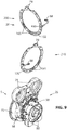
- FIGS. 7-11 each shows the hydraulic PTO 5 configured with the tower housing 70 angularly indexed with respect to the clutch housing 50.
- the clutch housing 50 remains in the same position, with the sump 80 at the lowest point, or in the "six o'clock" position.
- the multi-position adapter 26 includes vent line 88, and is shown from the tower housing side 200 and the clutch housing side 210.
- FIGS. 6-11 shows a vent line passage 160, which connects the air cavity in tower housing 70 ( FIG. 3 ) to an auxiliary vent line 88, which connects to the air cavity at the output end 60 ( FIG. 3 ) to ensure proper drainage to the sump 80 ( FIG. 3 ).
- the multi-position adapter 26 is shown to be indexed along with the tower housing 70 to match up the various hydraulic oil passages properly. As previously discussed, the hydraulic oil is picked up at the sump 80 and circulated through both the clutch housing 50 and the tower housing 70 while passing through the multi-position adapter 26.
- the multi-position adapter 26 therefore allows for the indexing of the tower housing 70 which also indexes the pump pads 75 thus allowing for a number of different configurations of the hydraulic PTO 5.
- the large number of configurations illustrated in FIGS. 7-11 allows the hydraulic PTO 5 to be installed in a large number of unique applications without ancillary hydraulic lines, pumps, or reservoirs with a simplified gravity-assisted drain and common sump 80.
- the unique configuration and adjustment of the multi-position adapter 26 allows the oil flow within the hydraulic PTO to be altered.
- the indexed configuration of the tower housing 70 with respect to the clutch housing 50 will require a unique oil flow to that as shown in FIG. 9 .
- the sump 80 would not be at the lowest point, thus preventing an internal oil pickup from getting the necessary oil.
- not being able to adjust the flow of oil between the tower housing 70 and the clutch housing 50 could cause oil to pool within certain parts of the tower when the pump pads 75 are adjusted such that they are at low points; see, for example, FIGS. 7 and 11 .
- Each Figure additionally shows the other side of passages 165 that allow the flow of spent hydraulic fluid to enter the sump 80 ( FIG. 2 ).
- the various positions in which the tower housing 70 and the clutch housing 50 may be indexed with respect to one another are not limited by what is shown in FIGS. 7 and 11 .
- the multi-position adapter may be uniquely manufactured with any number of through-holes 78, blocked ports 170, opening passages 165, and the like. As a result, it is foreseeable that the tower housing 70 may be indexed in an infinite amount of positions with respect to the clutch housing with a properly machined multi-position adapter 26.
- the multi-position adapter 26 is pre-manufactured with a number of different positions corresponding to the various oil inlet and outlets on each respective housing, thus allowing for a finite amount of pre-determined, indexed positions.
- FIGS. 7-11 illustrate blocked passages 155 that block oil when the tower housing 70 is indexed in certain configurations.
- the clutch housing 50 and tower housing 70 having different openings that can communicate with each other, with respective ones that are blocked from liquid-flow communication with each other, can be accommodated using the multi-position adapter 26.
- the tower housing 70 may have five openings so that no matter which position the tower housing 70 is oriented, there is always one opening at a six o'clock position.
- the clutch housing 50 may have three openings, with one at a six o'clock position, a second partial opening arranged to the right so that with the multi-position adapter 26 sandwiched between the clutch and tower housings, 50, 70, in a particular orientation of the multi-position adapter 26, will always have at least two openings in liquid-flow communication between the clutch and tower housings, 50, 70. This ensures that oil can always flush back into the sump 80 regardless of the orientation of the tower housing 70 relative to the clutch housing 50.
- the multi-position adapter is also preferably machined out of a flat piece of stock such as aluminum, iron, or steel, but may be made out of any other durable material.
- the various passages and ports described above in FIG. 6 need not be precision drilled.
- the multi-position adapter 26 acts as a large gasket between the clutch housing and the tower housing allowing for the communication of hydraulic oil between the two respective housings in a number of different orientations, as shown in FIGS. 7-11 .
- the multi-position adapter 26 may be made out of a compressible material such as a gasket material.
- the multi-position adapter 26 also requires a thickness to allow for hydraulic oil to pass through from the clutch housing 50 to the tower housing 70.
- the multi-position adapter 26 must also have a thickness of sufficient size to allow for the flow of hydraulic oil within the multi-position adapter 26 itself. This is best shown in FIG. 6 on the tower housing side 200. Passages 165 are cut into the thickness of the multi-position adapter 26 but not through the entire width, whereby the passages 165 provide oblong openings. These passages 165 may also be extended within the core of the multi-position adapter 26. It is also envisioned that the multi-position adapter may be made out of a multi-layer product where the passages are created with multiple laminations of each successive layer.
Landscapes
- Engineering & Computer Science (AREA)
- Mechanical Engineering (AREA)
- General Engineering & Computer Science (AREA)
- Transportation (AREA)
- Chemical & Material Sciences (AREA)
- Combustion & Propulsion (AREA)
- General Details Of Gearings (AREA)
- Hydraulic Clutches, Magnetic Clutches, Fluid Clutches, And Fluid Joints (AREA)
Description
- This application claims the benefit of priority to
U.S. Provisional Patent Application No. 62/296,978, filed February 18, 2016 - The preferred embodiments are directed to an industrial hydraulic power take-off unit (PTO) and more particularly, to a hydraulic PTO which does not require a clutch adjustment and which allows for maximum side load capability. The invention can be used wherever a disconnect is required between the driven equipment and the prime mover. The inventive PTO may be used in any stationary or mobile applications such as within the wood chipping industry where wood chippers are configured to chip whole trees of a large diameter, or perhaps on an agricultural tractor, dump truck, boom, winch, or the like.
- Hydraulic PTO units have been known to be used in a variety of applications. Historically, a single PTO unit was developed in such a way that it could be used in a number of applications with a number of different power sources. For example, one PTO design may be used to power a generator, a winch, a centrifugal pump, a blower, a compressor, and a fan. Each one of these applications may require a unique power source, such as a large diesel engine, a small gas engine, or anything in between or similar. Each unique application may also have a unique housing for the engine and PTO. For example, a generator will have a unique housing and footprint compared to that of a centrifugal pump.
- When configuring the PTO for use with each individual application, proper care must be taken in order to ensure that lubricating oil within the unit sufficiently flows through the necessary areas of the assembly. Due to the unique configuration of each engine and machine housing, the PTO unit is typically installed in various positions/angles, depending on the application. As proper flow of lubricating oil is critical to PTO longevity and performance, ancillary hydraulic lines, pumps, and reservoirs are commonly installed to ensure the lubricating oil reaches all the necessary components and properly drains. Known PTO units therefore require customization for each application.
-
US 2007/0163253 A1 shows a hydrostatic transaxle for a vehicle with a PTO included. - From
EP 2 719 912 A2 a vehicle PTO driveline is known, in which a PTO input shaft drives a PTO wet clutch which when engaged drives a PTO output shaft. - In
US 7,918,088 B1 a dual pump apparatus for use on a vehicle or industrial application having a housing in which a pair of hydraulic pumps are mounted and driven by a prime mover, is described. An auxiliary pump may be drivingly connected to a main drive shaft and a power take off unit may also be connected thereto. - Some PTOs have tower sections with tower drive ears or pads for driving accessories that extend outwardly from the main PTO housings that hold clutches and brakes of the PTOs. Different applications require different tower orientations relative to the main PTO housings, which can present challenges for the oil flow path routing for shared lubrication of the tower sections and main PTO housings. Accordingly, gravity could not be relied on to properly drain the oil to a wet sump, since each installation of the PTO most often requires a unique orientation. As a result, different tower orientations require different oil plumbing kits, including changing a current tower orientation to a different tower orientation if a machine gets reconfigured.
- Oil plumbing kits or adding supplemental hydraulic lines, pumps, and reservoirs to the PTO adds significant expense to the hardware as well as significant expense to the installation of the PTO. In order to keep design costs down, the design of the PTO would not be changed for each unique application. What is therefore needed is a PTO that is configured for installation in a variety of applications and can easily adapt to properly flow the lubricating oil, regardless of the orientation of the device. What is also needed is a PTO that can be adaptable without adding costly additional hydraulics including lines, pumps, and reservoirs. Finally, what is needed is a PTO lubrication system that uses gravity as the draining force of the lubrication system regardless of the orientation of the PTO.
- The preferred embodiments overcome the above-noted drawbacks by providing a heavy-duty industrial PTO that can be implemented in a variety of systems with gravity-assisted hydraulic oil drains.
- The prime mover for the inventive PTO can ideally be driven up to at least 1,243 horsepower (hp) at 1,800 revolutions per minute (rpm). The PTO is designed to withstand such demanding work conditions. The inventive PTO is ideal for a wide range of applications such as driving pumps, grinders, crushers, dredgers, chippers, shredders, heavy-duty drills, and more.
- The inventive PTO has a modular design allowing suitability for both side-load "P" and in-line "I" applications with the simple change of bearing carriers. An advanced control system, allowing for smooth engagement of the driven equipment, may also be utilized. Another feature is a pair of auxiliary drive pump pads with approximately 400 hp maximum capacity per tower, or about 550 hp maximum for both towers. The pump towers are rotatable by approximately 0°, 45°, and 90°, either clockwise or counter-clockwise, to allow for clearance in installation.
- The pump tower(s) preferably have at least two pump pads each. A wide variety of pump pads may be suitable for this purpose, such as SAE "A", SAE "B", SAE "C", SAE "D", SAE "E", or similar. In some embodiments, it may be desired or necessary to customize a pump pad for a specific PTO. The PTO may utilize an input housing similar to SAE #0, SAE #1, SAE #2, SAE #3, SAE #4, SAE #5, SAE #6, or any other preferably SAE size to prevent burnup in performance applications. The PTO may also utilize SAE 460, or SAE 355 input coupling or alternatively a flexible coupling. In some embodiments, the pump tower(s) may include an optional speed increase to handle the stress of higher engine speeds.
- The inventive PTO also optionally features an integrated hydraulic sump. Unlike a separate, externally mounted sump/reservoir, the integrated sump saves space and reduces installation cost. An innovative design, it allows for the installation of the standard charge/lube pump on a separate pad, freeing up all four auxiliary pads for customer use.
- A spring applied, hydraulically released brake (SAHR) has been added as a standard feature. An integral, mechanical brake release allows the output shaft to easily be rotated during service intervals of the driven equipment.
- An innovative, high-capacity brake with control logic is offered as an option. It slows the output when driving large masses in a shorter amount of time than conventional systems.
- The inventive PTO also utilizes an oil-filled, multiple disc, hydraulically actuated self-adjusting clutch. The inventive PTO has therefore been developed with a number of unique features that offer reliability, productivity, and power, including: integral mechanical brake release, optional integrated reservoir, and optional hydraulic gear pump. The inventive PTO may therefore be used in a wide range of heavy-duty applications including crushers, grinders, mulchers, dredgers, heavy-duty drills, and the like.
- The industrial hydraulic power take-off "PTO" includes a housing mounted between a prime mover and a piece of driven equipment. The housing includes a hydraulic section having a clutch housing with multiple passages directing oil throughout the PTO. Preferably, the clutch is a hydraulically actuated and self-adjusting clutch. Mechanical clutches tend to need adjusting of their actuating cable, whereas hydraulic clutches are usually self-adjusting. The self-adjusting clutch additionally allows for a high side-load capability.
- A tower housing may also have multiple passages directing oil through the tower housing. The tower housing is configured to connect to the clutch housing in multiple angularly indexed positions with respect to the clutch housing.
- An embodiment may utilize an actuator to switch, move, or adjust a secondary mechanism. The actuator may be a remote actuator, switch-input actuator, or any known or contemplated actuator to supply remote, operator-induced, or automated actuation of a secondary mechanism without departing from the spirit of the invention.
- Pilot bearings wear down, and a worn down or damaged pilot bearing creates high volume noises and may cause a transmission to jump out of gear as well as creates the potential for catastrophic transmission failure. The inventive PTO circumvents these potential problems by not utilizing a pilot bearing.
- In order to facilitate the indexing of the tower housing with respect to the clutch housing, a multi-position adapter is arranged between the tower and clutch housings. The multi-position adapter includes spaced-apart openings that align with various passages of the hydraulic and tower housings. When selecting an angularly indexed position to mount the tower housing with respect to the clutch housing, the multi-position adapter defines corresponding oil flow paths between respective ones of the passages of the hydraulic and tower housing and blocks flow through the remainder of the passages of the hydraulic and tower housings. This allows for the PTO to operate with a gravity drained hydraulic oil system with a common sump at the lowest point of the clutch housing, despite the indexed orientation of the adjustable tower housing.
- These and other features and advantages of the invention will become apparent to those skilled in the art from the following detailed description and the accompanying drawings. It should be understood, however, that the detailed description and specific examples, while indicating preferred embodiments of the present invention, are given by way of illustration and not of limitation. Many changes and modifications may be made within the scope of the present invention without departing from the spirit thereof, and the invention includes all such modifications.
- Preferred exemplary embodiments of the invention are illustrated in the accompanying drawings in which like reference numerals represent like parts throughout, and in which:
-
FIG. 1 is a simplified schematic representation of a piece of industrial equipment with an industrial drive incorporating a hydraulic PTO (power take-off) with a multiple-position force lubrication system; -
FIG. 2 is a pictorial end view of the hydraulic PTO ofFIG. 1 ; -
FIG. 3 is a cross-section view along section line A:A of the hydraulic PTO ofFIG. 2 ; -
FIG. 4 is a close-up view of Detail C and Detail B of the hydraulic PTO ofFIG. 3 ; -
FIG. 5 is a cross-section view along section line E:E of the hydraulic PTO ofFIG. 2 ; -
FIG. 6 is a raised perspective view of a multi-position adapter configured for use with the hydraulic PTO ofFIG. 2 showing a tower housing side and a clutch housing side of the same multi-position adapter; -
FIG. 7 is a raised perspective view of the hydraulic PTO using the multi-position adapter with the tower housing in a first, angularly indexed position; -
FIG. 8 is a raised perspective view of the hydraulic PTO using the multi-position adapter with the tower housing in a second, angularly indexed position; -
FIG. 9 is a raised perspective view of the hydraulic PTO using the multi-position adapter with the tower housing in a third, angularly indexed position; -
FIG. 10 is a raised perspective view of the hydraulic PTO using the multi-position adapter with the tower housing in a fourth, angularly indexed position; and -
FIG. 11 is a raised perspective view of the hydraulic PTO using the multi-position adapter with the tower housing in a fifth, angularly indexed position. - In describing preferred embodiments of the invention, which are illustrated in the drawings, specific terminology will be resorted to for the sake of clarity. However, it is not intended that the invention be limited to the specific terms so selected and it is to be understood that each specific term includes all technical equivalents, which operate in a similar manner to accomplish a similar purpose. For example, the words "connected", "attached", "coupled", or terms similar thereto are often used. They are not limited to direct connection but include connection through other elements where such connection is recognized as being equivalent by those skilled in the art.
- Referring now to the simplified schematic representation in
FIG. 1 , a hydraulic PTO (power take-off) 5 with a multi-position forcedlubrication system 10 and including asump 80 is shown implemented in anindustrial drive 15. Theindustrial drive 15 delivers power from aprime mover 20, which may be a high-power internal combustion engine, to a piece ofindustrial equipment 25.Industrial drive 15 is shown here configured for side-load power delivery and includes apulley arrangement 30 and belt(s) 35 that transmit power fromhydraulic PTO 5 to a driven component(s) of theindustrial equipment 25. The drive need not be limited to apulley arrangement 30 and belt(s) 35 as shown, but may be any known drive such as direct drive, chain drive, or the like. - The
industrial equipment 25 may be, for example, a whole-tree chipper or other industrial wood chipper, a heavy-duty pump system, a grinder, a crusher, a dredge, a shredder, or a heavy-duty drill system that has a large rotating mass such as a rotatable component(s) 40 that establishes large inertial loads while rotating. - Hydraulic oil is circulated throughout the
hydraulic PTO 5 to lubricate bearings and other components and to hydraulically actuate various components such as clutch and brake assemblies that transmit power from theprime mover 20 to thepower equipment 25. In order to simplify the hydraulics, the oil is gravity drained to a common integrated sump at the bottom of thehydraulic PTO 5, as explained in greater detail herein. - Referring now to
FIG. 2 , the body of thehydraulic PTO 5 is made up of atower housing 70 and a main PTO housing orclutch housing 50 that houses a clutch and brake assembly. Thetower housing 70 can be mounted to the prime mover 20 (FIG. 1 ) in a plurality of ways by clocking, or rotating, theclutch housing 50 with respect to thetower housing 70. A series offasteners 52 may be removed to allow for the clocking action and reattached once thetower housing 70 is in a suitable location for proper attachment to theprime mover 20. As shown inFIG. 2 , for example, a pair ofpump pads 75 is in a vertical orientation with thetower housing 70 affixed to theclutch housing 50 withfasteners 52. An additional feature shown is avent line 88, which allows for pressure equalization of the various oil ports within thehydraulic PTO 5. - Referring to
FIGS. 2 and3 ,hydraulic PTO 5 includes aninput end 55 configured for attachment to a variety of different prime movers 20 (FIG. 1 ) and anoutput end 60 configured to drive a plurality of devices with theoutput drive 34. Thetower housing 70 and twopump pads 75 are arranged between theinput end 55 and output end 60 of thehydraulic PTO 5. Thepump pads 75 may be configured to drive a plurality of devices. Thehydraulic PTO 5 may be attached to aprime mover 20, as shown, for example, inFIG. 1 , with a series of mountingholes 36 in a plurality of orientations. In any orientation, hydraulic oil flows within thehydraulic PTO 5 through a series of passages, as shown inFIGS. 3-5 . The hydraulic oil lubricates the internals of thehydraulic PTO 5 within both thetower housing 70 and theclutch housing 50 and is configured to operate with a gravity drain to acommon sump 80. Thesump 80 collects the hydraulic oil under the power of gravity and, as a result, is at the lowest point of theclutch housing 50. Once in thesump 80, the hydraulic oil can then be scavenged by a pump and recirculated throughout thehydraulic PTO 5 to lubricate the various internal parts. - The internal structure of the
hydraulic PTO 5 may be seen inFIG. 3 , which shows a cross-sectional view along the section line A:A ofFIG. 2 . In order to allow thetower housing 70 to be clocked with respect to theclutch housing 50, amulti-position adapter 26, or baffle plate, is placed between thetower housing 70 and theclutch housing 50. Themulti-position adapter 26 includes a plurality of holes that accept fasteners 52 (FIG. 2 ) to pass through and allow thetower housing 70 andclutch housing 50 to be mated together under clamping force of thefasteners 52. - A main hydraulic
oil supply passage 106 and a forcedlube supply port 104 provide the initial hydraulic oil supply for thehydraulic PTO 5. As shown inFIG. 2 , the mainoil supply passage 106 and the forcedlube supply port 104 are both proximate thesump 80 on theclutch housing 50. For this reason, the mainoil supply passage 106 and the forcedlube supply port 104 require the assistance of gravity to ensure a continuous supply of hydraulic oil in thesump 80. As discussed above, thesump 80 on theclutch housing 50 is required to be mounted to thetower housing 70 in an orientation as shown inFIG. 2 to allow gravity to maintain the hydraulic oil level within the sump. - Transitioning now to
FIG. 4 , a detailed view of Details B and C ofFIG. 3 is shown. Detail B is on the lower portion of theclutch housing 50. Themulti-position adapter 26 may be indexed to create anoil annulus 100 which lines up aninbound oil passage 102 to flow hydraulic oil from theclutch housing 50, around theoil annulus 100, and then flow to thetower housing 70 though theoutbound oil passage 96. Theoil annulus 100, as shown, is contained by the face and outside diameter of theclutch housing 50, the inside diameter of themulti-position adapter 26, and the face of thetower housing 70. Themulti-position adapter 26 includesseals 92 which are better seen in Detail C ofFIG. 3 . - As shown in Detail C of
FIG. 4 , seals 92 are located on each side of themulti-position adapter 26 to prevent the flow of hydraulic oil around themulti-position adapter 26. The hydraulic oil flows through theoil annulus 100 and is restricted by the body of themulti-position adapter 26 and seals 92 on each side of themulti-position adapter 26 to flow outbound throughoil passage 96. After hydraulic oil flows through theoutbound oil passage 96, it can then feed thepump pads 75 within thetower housing 70. In short, a plurality of oil passages is networked within each one of thetower housing 70 and theclutch housing 50. The network of oil passages within each respective housing are machined such that they communicate with each other to pass hydraulic oil back and forth. This allows for lubrication of the entirehydraulic PTO 5 with a simple pumping system and a common pump. - When the
tower housing 70 is attached to theclutch housing 50, the network of oil passages are lined up to one another to allow for this common oil communication. Themulti-position adapter 26 is therefore machined to include a plurality of pass-through ports and oil blocking ports to allow communication of hydraulic oil for proper flow between the housings and to block it where necessary, depending on the orientation of thetower housing 70 to theclutch housing 50, as discussed in detail with respect toFIGS. 6-11 . - After the hydraulic oil has circulated through both the
tower housing 70 and theclutch housing 50, it may then be drained back by gravity to thesump 80. As shown inFIG. 5 , asump drain opening 32 allows the return of spent hydraulic oil from thetower housing 70 into thesump 80 where the hydraulic oil may be picked up for repumping through thehydraulic PTO 5. Themulti-position adapter 26 prevents the hydraulic oil from flowing into an improper port machined into thetower housing 70 andclutch housing 50 and maintains the proper path of oil supply and oil draining. - For example,
FIG. 6 shows thetower housing side 200 and theclutch housing side 210 of themulti-position adapter 26. Looking to thetower housing side 200 of themulti-position adapter 26, a plurality of through-hole openings 78 is shown. The through-hole openings 78 are used for the fasteners 52 (FIG. 2 ) to connect the clutch housing 50 (FIG. 2 ),multi-position adapter 26, and the tower housing 70 (FIG. 2 ). Blockedpassages 155 block oil passages that are not used when thetower housing 70 is indexed in certain configurations.Passages 165 lead the spent hydraulic oil to drain back to the sump 80 (FIG. 2 ). Similarly, looking at theclutch housing side 210 of themulti-position adapter 26, blockedports 170 restrict the exit of hydraulic oil from theclutch housing 50, and also shows the other side ofpassages 165 that allow the flow of spent hydraulic fluid to enter the sump 80 (FIG. 2 ). Both themulti-position adapter 26 and thetower housing 70 can be indexed into a plurality of positions thus allowing hydraulic oil to communicate between thetower housing 70 and theclutch housing 50 while maintaining the proper flow of oil with a gravity-assisted drain back to thesump 80. In order to prevent air pockets or vacuum buildup of hydraulic oil within the various passages, avent line 88 may be installed into themulti-position adapter 26 with allows for pressure equalization of the various oil ports within thehydraulic PTO 5. - Regardless of the angularly indexed position of the
tower housing 70 with respect to theclutch housing 50, thevent line 88 may be adjusted to connect themulti-position adapter 26 to theclutch housing 50 thus allowing for proper ventilation and ensuring proper oil flow within thehydraulic PTO 5. -
FIGS. 7-11 each shows thehydraulic PTO 5 configured with thetower housing 70 angularly indexed with respect to theclutch housing 50. In each one ofFIGS. 7-11 , theclutch housing 50 remains in the same position, with thesump 80 at the lowest point, or in the "six o'clock" position. Above thehydraulic PTO 5 in each one ofFIGS. 7-11 , themulti-position adapter 26 includesvent line 88, and is shown from thetower housing side 200 and theclutch housing side 210. - Each of
FIGS. 6-11 shows avent line passage 160, which connects the air cavity in tower housing 70 (FIG. 3 ) to anauxiliary vent line 88, which connects to the air cavity at the output end 60 (FIG. 3 ) to ensure proper drainage to the sump 80 (FIG. 3 ). In each one of these respective views, themulti-position adapter 26 is shown to be indexed along with thetower housing 70 to match up the various hydraulic oil passages properly. As previously discussed, the hydraulic oil is picked up at thesump 80 and circulated through both theclutch housing 50 and thetower housing 70 while passing through themulti-position adapter 26. Themulti-position adapter 26 therefore allows for the indexing of thetower housing 70 which also indexes thepump pads 75 thus allowing for a number of different configurations of thehydraulic PTO 5. Ultimately, the large number of configurations illustrated inFIGS. 7-11 allows thehydraulic PTO 5 to be installed in a large number of unique applications without ancillary hydraulic lines, pumps, or reservoirs with a simplified gravity-assisted drain andcommon sump 80. - The unique configuration and adjustment of the
multi-position adapter 26 allows the oil flow within the hydraulic PTO to be altered. For example, the indexed configuration of thetower housing 70 with respect to theclutch housing 50, as shown inFIG. 7 , will require a unique oil flow to that as shown inFIG. 9 . This is due, in part, to the gravity assistance of the oil drain that ensures the hydraulic oil flows back to thesump 80. Without being able to change the flow of oil between thetower housing 70 and theclutch housing 50, thesump 80 would not be at the lowest point, thus preventing an internal oil pickup from getting the necessary oil. Additionally, not being able to adjust the flow of oil between thetower housing 70 and theclutch housing 50 could cause oil to pool within certain parts of the tower when thepump pads 75 are adjusted such that they are at low points; see, for example,FIGS. 7 and11 . - Each Figure additionally shows the other side of
passages 165 that allow the flow of spent hydraulic fluid to enter the sump 80 (FIG. 2 ). The various positions in which thetower housing 70 and theclutch housing 50 may be indexed with respect to one another are not limited by what is shown inFIGS. 7 and11 . The multi-position adapter may be uniquely manufactured with any number of through-holes 78, blockedports 170, openingpassages 165, and the like. As a result, it is foreseeable that thetower housing 70 may be indexed in an infinite amount of positions with respect to the clutch housing with a properly machinedmulti-position adapter 26. In the preferred embodiment shown, themulti-position adapter 26 is pre-manufactured with a number of different positions corresponding to the various oil inlet and outlets on each respective housing, thus allowing for a finite amount of pre-determined, indexed positions. Additionally,FIGS. 7-11 illustrate blockedpassages 155 that block oil when thetower housing 70 is indexed in certain configurations. - Therefore, the
clutch housing 50 andtower housing 70 having different openings that can communicate with each other, with respective ones that are blocked from liquid-flow communication with each other, can be accommodated using themulti-position adapter 26. For example, thetower housing 70 may have five openings so that no matter which position thetower housing 70 is oriented, there is always one opening at a six o'clock position. Theclutch housing 50 may have three openings, with one at a six o'clock position, a second partial opening arranged to the right so that with themulti-position adapter 26 sandwiched between the clutch and tower housings, 50, 70, in a particular orientation of themulti-position adapter 26, will always have at least two openings in liquid-flow communication between the clutch and tower housings, 50, 70. This ensures that oil can always flush back into thesump 80 regardless of the orientation of thetower housing 70 relative to theclutch housing 50. - The multi-position adapter is also preferably machined out of a flat piece of stock such as aluminum, iron, or steel, but may be made out of any other durable material. The various passages and ports described above in
FIG. 6 need not be precision drilled. Themulti-position adapter 26 acts as a large gasket between the clutch housing and the tower housing allowing for the communication of hydraulic oil between the two respective housings in a number of different orientations, as shown inFIGS. 7-11 . As a result, it is also envisioned that themulti-position adapter 26 may be made out of a compressible material such as a gasket material. Themulti-position adapter 26 also requires a thickness to allow for hydraulic oil to pass through from theclutch housing 50 to thetower housing 70. Themulti-position adapter 26 must also have a thickness of sufficient size to allow for the flow of hydraulic oil within themulti-position adapter 26 itself. This is best shown inFIG. 6 on thetower housing side 200.Passages 165 are cut into the thickness of themulti-position adapter 26 but not through the entire width, whereby thepassages 165 provide oblong openings. Thesepassages 165 may also be extended within the core of themulti-position adapter 26. It is also envisioned that the multi-position adapter may be made out of a multi-layer product where the passages are created with multiple laminations of each successive layer. - Although the best mode contemplated by the inventors of carrying out the present invention is disclosed above, practice of the above invention is not limited thereto. It will be manifest that various additions, modifications and rearrangements of the features of the present invention may be made without deviating from the scope of the underlying inventive concept.
Claims (8)
- An industrial hydraulic power take-off "PTO" (5), comprising:
a housing mounted between a prime mover (20) and a piece of driven equipment, the housing including,a hydraulic section having a clutch housing (50) with multiple passages directing oil through the PTO (5);a tower housing (70) having multiple passages directing oil through the tower housing (70), characterized in that the tower housing (70) is configured to connect to the clutch housing (50) in multiple angularly indexed positions with respect to the clutch housing (50); anda multi-position adapter (26) is arranged between the tower and clutch housings (70, 50), the multi-position adapter (26) having spaced apart openings that align with various passages (165) of the hydraulic and tower housings (70), wherein selecting an angularly indexed position of the multi-position adapter (26) defines corresponding oil flow paths (36) between respective ones of the passages of the hydraulic and tower housing (70) and blocks flow through the remainder of the passages (165) of the hydraulic and tower housings (70). - The power take-off (5) of claim 1, further comprising an oil sump (80) located at a lower portion of the housing, wherein the oil sump (80) receives a volume of hydraulic oil.
- The power take-off (5) of claim 2, further comprising a lube pump, wherein said lube pump recirculates oil received in the oil sump (80) throughout the multiple passages (165).
- The power take-off (5) of claim 3, further comprising a vent coupled to the multi-position adapter (26) and located at a distal end of a multiple passage (165) of oil throughout the PTO (5).
- The power take-off (5) of claim 1, further comprising a spring applied, hydraulically released brake.
- The power take-off (5) of claim 5, further comprising a mechanical brake release.
- The power take-off (5) of claim 5, further comprising an oil-filled, multiple disc, hydraulically-actuated, self-adjusting clutch.
- The power take-off (5) of claim 7, further comprising a hydraulic gear pump.
Applications Claiming Priority (2)
| Application Number | Priority Date | Filing Date | Title |
|---|---|---|---|
| US201662296978P | 2016-02-18 | 2016-02-18 | |
| PCT/US2017/017921 WO2017142915A1 (en) | 2016-02-18 | 2017-02-15 | Integrated multi-position force lubrication system |
Publications (3)
| Publication Number | Publication Date |
|---|---|
| EP3416846A1 EP3416846A1 (en) | 2018-12-26 |
| EP3416846A4 EP3416846A4 (en) | 2019-11-27 |
| EP3416846B1 true EP3416846B1 (en) | 2021-03-24 |
Family
ID=59626326
Family Applications (1)
| Application Number | Title | Priority Date | Filing Date |
|---|---|---|---|
| EP17753735.4A Not-in-force EP3416846B1 (en) | 2016-02-18 | 2017-02-15 | Industrial hydraulic power take off |
Country Status (4)
| Country | Link |
|---|---|
| US (1) | US10228027B2 (en) |
| EP (1) | EP3416846B1 (en) |
| CN (1) | CN109070740B (en) |
| WO (1) | WO2017142915A1 (en) |
Families Citing this family (3)
| Publication number | Priority date | Publication date | Assignee | Title |
|---|---|---|---|---|
| US11811296B2 (en) | 2020-02-12 | 2023-11-07 | Deere & Company | Electric machine with configurable stator/rotor cooling |
| US11780319B2 (en) * | 2020-04-07 | 2023-10-10 | Deere & Company | Work vehicle electric drive assembly cooling arrangement |
| US11787275B2 (en) * | 2020-06-10 | 2023-10-17 | Deere & Company | Electric drive with hydraulic mounting interface |
Family Cites Families (23)
| Publication number | Priority date | Publication date | Assignee | Title |
|---|---|---|---|---|
| JPH0547321Y2 (en) | 1988-07-18 | 1993-12-13 | ||
| US5524508A (en) | 1994-09-19 | 1996-06-11 | Peters; Don | Adapter for coupling an engine and transmission |
| US6224289B1 (en) * | 1998-12-18 | 2001-05-01 | Kevin D. Redd | Power takeoff unit-driven unit adapter with sump lubrication |
| CN2371062Y (en) * | 1999-03-15 | 2000-03-29 | 重汽集团济南齿轮厂 | Double-power output clutch |
| US6227333B1 (en) | 1999-06-24 | 2001-05-08 | Zf Meritor, Llc | Transmission housing with integral pump assembly |
| US6305515B1 (en) | 1999-07-20 | 2001-10-23 | Power Transmission Technology, Inc. | Hydraulically actuated power takeoff clutch assembly |
| JP4338138B2 (en) * | 2004-09-16 | 2009-10-07 | 株式会社 神崎高級工機製作所 | Pump device |
| US7377105B1 (en) * | 2004-11-12 | 2008-05-27 | Hydro-Gear Limited Partnership | Dual pump assembly |
| EP1808324B1 (en) * | 2006-01-16 | 2010-03-17 | Kanzaki Kokyukoki Mfg. Co., Ltd. | Hydrostatic transaxle |
| US8312858B2 (en) * | 2006-12-22 | 2012-11-20 | Kohler Co. | System and method for lubricating power transmitting elements |
| CN101344023A (en) * | 2007-07-10 | 2009-01-14 | 天津一汽夏利汽车股份有限公司 | Gasoline Engine Integrated Valve Timing Continuous Adjustment Device |
| US8561283B1 (en) | 2007-10-29 | 2013-10-22 | Prestolite Performance, Llc | Method to provide a universal bellhousing between an engine and transmission of a vehicle |
| DE102008043734B4 (en) | 2008-11-14 | 2023-05-04 | Zf Friedrichshafen Ag | Transmission device with a hydraulic system having a transmission main pump device |
| CA2740996C (en) * | 2008-12-19 | 2016-02-16 | Mouvex | Device for pressurising a fluid, to be directly mounted on a power take-off |
| US8408363B2 (en) * | 2010-01-19 | 2013-04-02 | Deere & Company | PTO lube control system |
| DE102010007638B4 (en) * | 2010-02-05 | 2022-03-24 | Dr. Ing. H.C. F. Porsche Aktiengesellschaft | powertrain |
| DE102011085255A1 (en) * | 2011-10-26 | 2013-05-02 | Deere & Company | PTO |
| DE102011086276A1 (en) | 2011-11-14 | 2013-05-16 | Zf Friedrichshafen Ag | Arrangement for lubricating oil supply of the chain drive for driving an off-axis to the torque converter arranged transmission oil pump in a motor vehicle with a torque converter |
| US8991274B2 (en) * | 2012-07-06 | 2015-03-31 | Cnh Industrial America Llc | Mounting surface of an agricultural work vehicle power takeoff system |
| GB201218234D0 (en) * | 2012-10-11 | 2012-11-28 | Agco Int Gmbh | PTO drivelines |
| CN203516550U (en) * | 2013-10-22 | 2014-04-02 | 新疆永成农业装备制造股份有限公司 | Clutch device of tractor front power output shaft |
| WO2017142893A1 (en) * | 2016-02-18 | 2017-08-24 | Twin Disc, Inc. | Hydraulic power take-off with multiple-force brake system for industrial drives |
| PL3416847T3 (en) * | 2016-02-18 | 2024-01-22 | Twin Disc, Inc. | Hydraulic power take-off with brake disconnect system for industrial drives |
-
2017
- 2017-02-15 US US15/433,532 patent/US10228027B2/en active Active
- 2017-02-15 WO PCT/US2017/017921 patent/WO2017142915A1/en not_active Ceased
- 2017-02-15 CN CN201780023858.1A patent/CN109070740B/en not_active Expired - Fee Related
- 2017-02-15 EP EP17753735.4A patent/EP3416846B1/en not_active Not-in-force
Non-Patent Citations (1)
| Title |
|---|
| None * |
Also Published As
| Publication number | Publication date |
|---|---|
| US20170241488A1 (en) | 2017-08-24 |
| US10228027B2 (en) | 2019-03-12 |
| CN109070740A (en) | 2018-12-21 |
| EP3416846A4 (en) | 2019-11-27 |
| WO2017142915A1 (en) | 2017-08-24 |
| EP3416846A1 (en) | 2018-12-26 |
| CN109070740B (en) | 2021-08-27 |
Similar Documents
| Publication | Publication Date | Title |
|---|---|---|
| US8312858B2 (en) | System and method for lubricating power transmitting elements | |
| US9068614B2 (en) | Arrangement for supplying oil to a brake | |
| US6227333B1 (en) | Transmission housing with integral pump assembly | |
| US10228027B2 (en) | Integrated multi-position force lubrication system | |
| EP0045864B1 (en) | Add-on forced lubrication system | |
| US7918088B1 (en) | Dual pump assembly | |
| US8104277B1 (en) | Pump assembly | |
| US8475319B2 (en) | Final drive comprising a lubrication system | |
| US4283968A (en) | Housing assembly for electric vehicle transaxle | |
| WO2008079186A1 (en) | System and method for lubricating power transmitting elements | |
| JP4499689B2 (en) | Continuously variable transmission | |
| WO2016064599A1 (en) | Modular power take-off assembly | |
| US9611930B2 (en) | Lubrication of power train components | |
| US6189655B1 (en) | Transmission housing with integral lubrication system | |
| US20060213477A1 (en) | Pump combination | |
| JP3505814B2 (en) | Transmission forced lubrication system | |
| US7162870B1 (en) | Pump assembly | |
| US20050284256A1 (en) | Drive system for mobile vehicles | |
| US6205779B1 (en) | Integral hub driven gears | |
| US20130330224A1 (en) | Multi-cluster gear device | |
| US7591514B2 (en) | Cutter head for an excavator machine | |
| CA2040869C (en) | Pump bearing system | |
| US4275617A (en) | Hydraulic system for a ratio change transmission | |
| JPS5926825B2 (en) | Planetary gear reduction mechanism | |
| EP0881365B1 (en) | An engine structure for internal combustion engines |
Legal Events
| Date | Code | Title | Description |
|---|---|---|---|
| STAA | Information on the status of an ep patent application or granted ep patent |
Free format text: STATUS: THE INTERNATIONAL PUBLICATION HAS BEEN MADE |
|
| PUAI | Public reference made under article 153(3) epc to a published international application that has entered the european phase |
Free format text: ORIGINAL CODE: 0009012 |
|
| STAA | Information on the status of an ep patent application or granted ep patent |
Free format text: STATUS: REQUEST FOR EXAMINATION WAS MADE |
|
| 17P | Request for examination filed |
Effective date: 20180828 |
|
| AK | Designated contracting states |
Kind code of ref document: A1 Designated state(s): AL AT BE BG CH CY CZ DE DK EE ES FI FR GB GR HR HU IE IS IT LI LT LU LV MC MK MT NL NO PL PT RO RS SE SI SK SM TR |
|
| AX | Request for extension of the european patent |
Extension state: BA ME |
|
| DAV | Request for validation of the european patent (deleted) | ||
| DAX | Request for extension of the european patent (deleted) | ||
| A4 | Supplementary search report drawn up and despatched |
Effective date: 20191030 |
|
| RIC1 | Information provided on ipc code assigned before grant |
Ipc: B60K 17/02 20060101ALI20191024BHEP Ipc: B60K 17/28 20060101AFI20191024BHEP |
|
| GRAP | Despatch of communication of intention to grant a patent |
Free format text: ORIGINAL CODE: EPIDOSNIGR1 |
|
| STAA | Information on the status of an ep patent application or granted ep patent |
Free format text: STATUS: GRANT OF PATENT IS INTENDED |
|
| INTG | Intention to grant announced |
Effective date: 20200914 |
|
| GRAS | Grant fee paid |
Free format text: ORIGINAL CODE: EPIDOSNIGR3 |
|
| GRAA | (expected) grant |
Free format text: ORIGINAL CODE: 0009210 |
|
| STAA | Information on the status of an ep patent application or granted ep patent |
Free format text: STATUS: THE PATENT HAS BEEN GRANTED |
|
| AK | Designated contracting states |
Kind code of ref document: B1 Designated state(s): AL AT BE BG CH CY CZ DE DK EE ES FI FR GB GR HR HU IE IS IT LI LT LU LV MC MK MT NL NO PL PT RO RS SE SI SK SM TR |
|
| REG | Reference to a national code |
Ref country code: GB Ref legal event code: FG4D |
|
| REG | Reference to a national code |
Ref country code: CH Ref legal event code: EP |
|
| REG | Reference to a national code |
Ref country code: IE Ref legal event code: FG4D |
|
| REG | Reference to a national code |
Ref country code: DE Ref legal event code: R096 Ref document number: 602017035254 Country of ref document: DE Ref country code: AT Ref legal event code: REF Ref document number: 1374139 Country of ref document: AT Kind code of ref document: T Effective date: 20210415 |
|
| REG | Reference to a national code |
Ref country code: NL Ref legal event code: FP |
|
| REG | Reference to a national code |
Ref country code: FI Ref legal event code: FGE |
|
| REG | Reference to a national code |
Ref country code: LT Ref legal event code: MG9D |
|
| PG25 | Lapsed in a contracting state [announced via postgrant information from national office to epo] |
Ref country code: BG Free format text: LAPSE BECAUSE OF FAILURE TO SUBMIT A TRANSLATION OF THE DESCRIPTION OR TO PAY THE FEE WITHIN THE PRESCRIBED TIME-LIMIT Effective date: 20210624 Ref country code: NO Free format text: LAPSE BECAUSE OF FAILURE TO SUBMIT A TRANSLATION OF THE DESCRIPTION OR TO PAY THE FEE WITHIN THE PRESCRIBED TIME-LIMIT Effective date: 20210624 Ref country code: GR Free format text: LAPSE BECAUSE OF FAILURE TO SUBMIT A TRANSLATION OF THE DESCRIPTION OR TO PAY THE FEE WITHIN THE PRESCRIBED TIME-LIMIT Effective date: 20210625 Ref country code: HR Free format text: LAPSE BECAUSE OF FAILURE TO SUBMIT A TRANSLATION OF THE DESCRIPTION OR TO PAY THE FEE WITHIN THE PRESCRIBED TIME-LIMIT Effective date: 20210324 |
|
| PG25 | Lapsed in a contracting state [announced via postgrant information from national office to epo] |
Ref country code: LV Free format text: LAPSE BECAUSE OF FAILURE TO SUBMIT A TRANSLATION OF THE DESCRIPTION OR TO PAY THE FEE WITHIN THE PRESCRIBED TIME-LIMIT Effective date: 20210324 Ref country code: RS Free format text: LAPSE BECAUSE OF FAILURE TO SUBMIT A TRANSLATION OF THE DESCRIPTION OR TO PAY THE FEE WITHIN THE PRESCRIBED TIME-LIMIT Effective date: 20210324 Ref country code: SE Free format text: LAPSE BECAUSE OF FAILURE TO SUBMIT A TRANSLATION OF THE DESCRIPTION OR TO PAY THE FEE WITHIN THE PRESCRIBED TIME-LIMIT Effective date: 20210324 |
|
| REG | Reference to a national code |
Ref country code: AT Ref legal event code: MK05 Ref document number: 1374139 Country of ref document: AT Kind code of ref document: T Effective date: 20210324 |
|
| PG25 | Lapsed in a contracting state [announced via postgrant information from national office to epo] |
Ref country code: CZ Free format text: LAPSE BECAUSE OF FAILURE TO SUBMIT A TRANSLATION OF THE DESCRIPTION OR TO PAY THE FEE WITHIN THE PRESCRIBED TIME-LIMIT Effective date: 20210324 Ref country code: EE Free format text: LAPSE BECAUSE OF FAILURE TO SUBMIT A TRANSLATION OF THE DESCRIPTION OR TO PAY THE FEE WITHIN THE PRESCRIBED TIME-LIMIT Effective date: 20210324 Ref country code: LT Free format text: LAPSE BECAUSE OF FAILURE TO SUBMIT A TRANSLATION OF THE DESCRIPTION OR TO PAY THE FEE WITHIN THE PRESCRIBED TIME-LIMIT Effective date: 20210324 Ref country code: SM Free format text: LAPSE BECAUSE OF FAILURE TO SUBMIT A TRANSLATION OF THE DESCRIPTION OR TO PAY THE FEE WITHIN THE PRESCRIBED TIME-LIMIT Effective date: 20210324 Ref country code: AT Free format text: LAPSE BECAUSE OF FAILURE TO SUBMIT A TRANSLATION OF THE DESCRIPTION OR TO PAY THE FEE WITHIN THE PRESCRIBED TIME-LIMIT Effective date: 20210324 |
|
| PG25 | Lapsed in a contracting state [announced via postgrant information from national office to epo] |
Ref country code: IS Free format text: LAPSE BECAUSE OF FAILURE TO SUBMIT A TRANSLATION OF THE DESCRIPTION OR TO PAY THE FEE WITHIN THE PRESCRIBED TIME-LIMIT Effective date: 20210724 Ref country code: PT Free format text: LAPSE BECAUSE OF FAILURE TO SUBMIT A TRANSLATION OF THE DESCRIPTION OR TO PAY THE FEE WITHIN THE PRESCRIBED TIME-LIMIT Effective date: 20210726 Ref country code: PL Free format text: LAPSE BECAUSE OF FAILURE TO SUBMIT A TRANSLATION OF THE DESCRIPTION OR TO PAY THE FEE WITHIN THE PRESCRIBED TIME-LIMIT Effective date: 20210324 Ref country code: SK Free format text: LAPSE BECAUSE OF FAILURE TO SUBMIT A TRANSLATION OF THE DESCRIPTION OR TO PAY THE FEE WITHIN THE PRESCRIBED TIME-LIMIT Effective date: 20210324 Ref country code: RO Free format text: LAPSE BECAUSE OF FAILURE TO SUBMIT A TRANSLATION OF THE DESCRIPTION OR TO PAY THE FEE WITHIN THE PRESCRIBED TIME-LIMIT Effective date: 20210324 |
|
| REG | Reference to a national code |
Ref country code: DE Ref legal event code: R097 Ref document number: 602017035254 Country of ref document: DE |
|
| PG25 | Lapsed in a contracting state [announced via postgrant information from national office to epo] |
Ref country code: ES Free format text: LAPSE BECAUSE OF FAILURE TO SUBMIT A TRANSLATION OF THE DESCRIPTION OR TO PAY THE FEE WITHIN THE PRESCRIBED TIME-LIMIT Effective date: 20210324 Ref country code: DK Free format text: LAPSE BECAUSE OF FAILURE TO SUBMIT A TRANSLATION OF THE DESCRIPTION OR TO PAY THE FEE WITHIN THE PRESCRIBED TIME-LIMIT Effective date: 20210324 Ref country code: AL Free format text: LAPSE BECAUSE OF FAILURE TO SUBMIT A TRANSLATION OF THE DESCRIPTION OR TO PAY THE FEE WITHIN THE PRESCRIBED TIME-LIMIT Effective date: 20210324 |
|
| PLBE | No opposition filed within time limit |
Free format text: ORIGINAL CODE: 0009261 |
|
| STAA | Information on the status of an ep patent application or granted ep patent |
Free format text: STATUS: NO OPPOSITION FILED WITHIN TIME LIMIT |
|
| PG25 | Lapsed in a contracting state [announced via postgrant information from national office to epo] |
Ref country code: SI Free format text: LAPSE BECAUSE OF FAILURE TO SUBMIT A TRANSLATION OF THE DESCRIPTION OR TO PAY THE FEE WITHIN THE PRESCRIBED TIME-LIMIT Effective date: 20210324 |
|
| 26N | No opposition filed |
Effective date: 20220104 |
|
| PG25 | Lapsed in a contracting state [announced via postgrant information from national office to epo] |
Ref country code: IS Free format text: LAPSE BECAUSE OF FAILURE TO SUBMIT A TRANSLATION OF THE DESCRIPTION OR TO PAY THE FEE WITHIN THE PRESCRIBED TIME-LIMIT Effective date: 20210724 |
|
| PG25 | Lapsed in a contracting state [announced via postgrant information from national office to epo] |
Ref country code: MC Free format text: LAPSE BECAUSE OF FAILURE TO SUBMIT A TRANSLATION OF THE DESCRIPTION OR TO PAY THE FEE WITHIN THE PRESCRIBED TIME-LIMIT Effective date: 20210324 |
|
| REG | Reference to a national code |
Ref country code: CH Ref legal event code: PL |
|
| PG25 | Lapsed in a contracting state [announced via postgrant information from national office to epo] |
Ref country code: LU Free format text: LAPSE BECAUSE OF NON-PAYMENT OF DUE FEES Effective date: 20220215 |
|
| PG25 | Lapsed in a contracting state [announced via postgrant information from national office to epo] |
Ref country code: LI Free format text: LAPSE BECAUSE OF NON-PAYMENT OF DUE FEES Effective date: 20220228 Ref country code: CH Free format text: LAPSE BECAUSE OF NON-PAYMENT OF DUE FEES Effective date: 20220228 |
|
| PGFP | Annual fee paid to national office [announced via postgrant information from national office to epo] |
Ref country code: NL Payment date: 20230220 Year of fee payment: 7 |
|
| PGFP | Annual fee paid to national office [announced via postgrant information from national office to epo] |
Ref country code: IE Payment date: 20230215 Year of fee payment: 7 Ref country code: FR Payment date: 20230217 Year of fee payment: 7 Ref country code: FI Payment date: 20230222 Year of fee payment: 7 |
|
| PGFP | Annual fee paid to national office [announced via postgrant information from national office to epo] |
Ref country code: IT Payment date: 20230228 Year of fee payment: 7 Ref country code: GB Payment date: 20230221 Year of fee payment: 7 Ref country code: DE Payment date: 20230117 Year of fee payment: 7 Ref country code: BE Payment date: 20230220 Year of fee payment: 7 |
|
| PG25 | Lapsed in a contracting state [announced via postgrant information from national office to epo] |
Ref country code: HU Free format text: LAPSE BECAUSE OF FAILURE TO SUBMIT A TRANSLATION OF THE DESCRIPTION OR TO PAY THE FEE WITHIN THE PRESCRIBED TIME-LIMIT; INVALID AB INITIO Effective date: 20170215 |
|
| PG25 | Lapsed in a contracting state [announced via postgrant information from national office to epo] |
Ref country code: MK Free format text: LAPSE BECAUSE OF FAILURE TO SUBMIT A TRANSLATION OF THE DESCRIPTION OR TO PAY THE FEE WITHIN THE PRESCRIBED TIME-LIMIT Effective date: 20210324 Ref country code: CY Free format text: LAPSE BECAUSE OF FAILURE TO SUBMIT A TRANSLATION OF THE DESCRIPTION OR TO PAY THE FEE WITHIN THE PRESCRIBED TIME-LIMIT Effective date: 20210324 |
|
| REG | Reference to a national code |
Ref country code: DE Ref legal event code: R119 Ref document number: 602017035254 Country of ref document: DE |
|
| PG25 | Lapsed in a contracting state [announced via postgrant information from national office to epo] |
Ref country code: MT Free format text: LAPSE BECAUSE OF FAILURE TO SUBMIT A TRANSLATION OF THE DESCRIPTION OR TO PAY THE FEE WITHIN THE PRESCRIBED TIME-LIMIT Effective date: 20210324 |
|
| REG | Reference to a national code |
Ref country code: NL Ref legal event code: MM Effective date: 20240301 |
|
| PG25 | Lapsed in a contracting state [announced via postgrant information from national office to epo] |
Ref country code: FI Free format text: LAPSE BECAUSE OF NON-PAYMENT OF DUE FEES Effective date: 20240215 |
|
| GBPC | Gb: european patent ceased through non-payment of renewal fee |
Effective date: 20240215 |
|
| PG25 | Lapsed in a contracting state [announced via postgrant information from national office to epo] |
Ref country code: FI Free format text: LAPSE BECAUSE OF NON-PAYMENT OF DUE FEES Effective date: 20240215 |
|
| PG25 | Lapsed in a contracting state [announced via postgrant information from national office to epo] |
Ref country code: NL Free format text: LAPSE BECAUSE OF NON-PAYMENT OF DUE FEES Effective date: 20240301 |
|
| PG25 | Lapsed in a contracting state [announced via postgrant information from national office to epo] |
Ref country code: NL Free format text: LAPSE BECAUSE OF NON-PAYMENT OF DUE FEES Effective date: 20240301 |
|
| REG | Reference to a national code |
Ref country code: BE Ref legal event code: MM Effective date: 20240229 |
|
| PG25 | Lapsed in a contracting state [announced via postgrant information from national office to epo] |
Ref country code: DE Free format text: LAPSE BECAUSE OF NON-PAYMENT OF DUE FEES Effective date: 20240903 |
|
| PG25 | Lapsed in a contracting state [announced via postgrant information from national office to epo] |
Ref country code: BE Free format text: LAPSE BECAUSE OF NON-PAYMENT OF DUE FEES Effective date: 20240229 |
|
| PG25 | Lapsed in a contracting state [announced via postgrant information from national office to epo] |
Ref country code: GB Free format text: LAPSE BECAUSE OF NON-PAYMENT OF DUE FEES Effective date: 20240215 |
|
| PG25 | Lapsed in a contracting state [announced via postgrant information from national office to epo] |
Ref country code: FR Free format text: LAPSE BECAUSE OF NON-PAYMENT OF DUE FEES Effective date: 20240229 |
|
| PG25 | Lapsed in a contracting state [announced via postgrant information from national office to epo] |
Ref country code: IE Free format text: LAPSE BECAUSE OF NON-PAYMENT OF DUE FEES Effective date: 20240215 |
|
| PG25 | Lapsed in a contracting state [announced via postgrant information from national office to epo] |
Ref country code: IE Free format text: LAPSE BECAUSE OF NON-PAYMENT OF DUE FEES Effective date: 20240215 Ref country code: GB Free format text: LAPSE BECAUSE OF NON-PAYMENT OF DUE FEES Effective date: 20240215 Ref country code: FR Free format text: LAPSE BECAUSE OF NON-PAYMENT OF DUE FEES Effective date: 20240229 Ref country code: DE Free format text: LAPSE BECAUSE OF NON-PAYMENT OF DUE FEES Effective date: 20240903 Ref country code: BE Free format text: LAPSE BECAUSE OF NON-PAYMENT OF DUE FEES Effective date: 20240229 |
|
| PG25 | Lapsed in a contracting state [announced via postgrant information from national office to epo] |
Ref country code: IT Free format text: LAPSE BECAUSE OF NON-PAYMENT OF DUE FEES Effective date: 20240215 |
|
| PG25 | Lapsed in a contracting state [announced via postgrant information from national office to epo] |
Ref country code: TR Free format text: LAPSE BECAUSE OF FAILURE TO SUBMIT A TRANSLATION OF THE DESCRIPTION OR TO PAY THE FEE WITHIN THE PRESCRIBED TIME-LIMIT Effective date: 20210324 |