EP3416599B1 - Apparatus for cataract extraction - Google Patents
Apparatus for cataract extraction Download PDFInfo
- Publication number
- EP3416599B1 EP3416599B1 EP17708938.0A EP17708938A EP3416599B1 EP 3416599 B1 EP3416599 B1 EP 3416599B1 EP 17708938 A EP17708938 A EP 17708938A EP 3416599 B1 EP3416599 B1 EP 3416599B1
- Authority
- EP
- European Patent Office
- Prior art keywords
- wire
- extraction device
- lens
- lumen
- delivery shaft
- Prior art date
- Legal status (The legal status is an assumption and is not a legal conclusion. Google has not performed a legal analysis and makes no representation as to the accuracy of the status listed.)
- Active
Links
Images













Classifications
-
- A—HUMAN NECESSITIES
- A61—MEDICAL OR VETERINARY SCIENCE; HYGIENE
- A61F—FILTERS IMPLANTABLE INTO BLOOD VESSELS; PROSTHESES; DEVICES PROVIDING PATENCY TO, OR PREVENTING COLLAPSING OF, TUBULAR STRUCTURES OF THE BODY, e.g. STENTS; ORTHOPAEDIC, NURSING OR CONTRACEPTIVE DEVICES; FOMENTATION; TREATMENT OR PROTECTION OF EYES OR EARS; BANDAGES, DRESSINGS OR ABSORBENT PADS; FIRST-AID KITS
- A61F9/00—Methods or devices for treatment of the eyes; Devices for putting in contact-lenses; Devices to correct squinting; Apparatus to guide the blind; Protective devices for the eyes, carried on the body or in the hand
- A61F9/007—Methods or devices for eye surgery
- A61F9/00736—Instruments for removal of intra-ocular material or intra-ocular injection, e.g. cataract instruments
-
- A—HUMAN NECESSITIES
- A61—MEDICAL OR VETERINARY SCIENCE; HYGIENE
- A61B—DIAGNOSIS; SURGERY; IDENTIFICATION
- A61B17/00—Surgical instruments, devices or methods
- A61B17/32—Surgical cutting instruments
- A61B17/320016—Endoscopic cutting instruments, e.g. arthroscopes, resectoscopes
-
- A—HUMAN NECESSITIES
- A61—MEDICAL OR VETERINARY SCIENCE; HYGIENE
- A61B—DIAGNOSIS; SURGERY; IDENTIFICATION
- A61B17/00—Surgical instruments, devices or methods
- A61B17/32—Surgical cutting instruments
- A61B17/3205—Excision instruments
- A61B17/32053—Punch like cutting instruments, e.g. using a cylindrical or oval knife
-
- A—HUMAN NECESSITIES
- A61—MEDICAL OR VETERINARY SCIENCE; HYGIENE
- A61B—DIAGNOSIS; SURGERY; IDENTIFICATION
- A61B17/00—Surgical instruments, devices or methods
- A61B17/32—Surgical cutting instruments
- A61B17/3205—Excision instruments
- A61B17/32056—Surgical snare instruments
-
- A—HUMAN NECESSITIES
- A61—MEDICAL OR VETERINARY SCIENCE; HYGIENE
- A61B—DIAGNOSIS; SURGERY; IDENTIFICATION
- A61B17/00—Surgical instruments, devices or methods
- A61B17/22—Implements for squeezing-off ulcers or the like on inner organs of the body; Implements for scraping-out cavities of body organs, e.g. bones; for invasive removal or destruction of calculus using mechanical vibrations; for removing obstructions in blood vessels, not otherwise provided for
- A61B17/22031—Gripping instruments, e.g. forceps, for removing or smashing calculi
-
- A—HUMAN NECESSITIES
- A61—MEDICAL OR VETERINARY SCIENCE; HYGIENE
- A61B—DIAGNOSIS; SURGERY; IDENTIFICATION
- A61B17/00—Surgical instruments, devices or methods
- A61B17/22—Implements for squeezing-off ulcers or the like on inner organs of the body; Implements for scraping-out cavities of body organs, e.g. bones; for invasive removal or destruction of calculus using mechanical vibrations; for removing obstructions in blood vessels, not otherwise provided for
- A61B17/221—Gripping devices in the form of loops or baskets for gripping calculi or similar types of obstructions
-
- A—HUMAN NECESSITIES
- A61—MEDICAL OR VETERINARY SCIENCE; HYGIENE
- A61B—DIAGNOSIS; SURGERY; IDENTIFICATION
- A61B17/00—Surgical instruments, devices or methods
- A61B17/22—Implements for squeezing-off ulcers or the like on inner organs of the body; Implements for scraping-out cavities of body organs, e.g. bones; for invasive removal or destruction of calculus using mechanical vibrations; for removing obstructions in blood vessels, not otherwise provided for
- A61B17/221—Gripping devices in the form of loops or baskets for gripping calculi or similar types of obstructions
- A61B2017/2217—Gripping devices in the form of loops or baskets for gripping calculi or similar types of obstructions single wire changing shape to a gripping configuration
-
- A—HUMAN NECESSITIES
- A61—MEDICAL OR VETERINARY SCIENCE; HYGIENE
- A61B—DIAGNOSIS; SURGERY; IDENTIFICATION
- A61B17/00—Surgical instruments, devices or methods
- A61B17/30—Surgical pincettes, i.e. surgical tweezers without pivotal connections
- A61B2017/306—Surgical pincettes, i.e. surgical tweezers without pivotal connections holding by means of suction
-
- A—HUMAN NECESSITIES
- A61—MEDICAL OR VETERINARY SCIENCE; HYGIENE
- A61B—DIAGNOSIS; SURGERY; IDENTIFICATION
- A61B17/00—Surgical instruments, devices or methods
- A61B17/32—Surgical cutting instruments
- A61B17/320016—Endoscopic cutting instruments, e.g. arthroscopes, resectoscopes
- A61B2017/32004—Endoscopic cutting instruments, e.g. arthroscopes, resectoscopes having a laterally movable cutting member at its most distal end which remains within the contours of said end
-
- A—HUMAN NECESSITIES
- A61—MEDICAL OR VETERINARY SCIENCE; HYGIENE
- A61B—DIAGNOSIS; SURGERY; IDENTIFICATION
- A61B17/00—Surgical instruments, devices or methods
- A61B17/32—Surgical cutting instruments
- A61B2017/32006—Surgical cutting instruments with a cutting strip, band or chain, e.g. like a chainsaw
Definitions
- the present disclosure generally relates to surgical devices and, in particular, relates to cataract extraction devices.
- Cataracts often cause loss of vision by clouding the lens of the eye. Cataract surgery is often performed, in which the lens is removed from the eye and replaced with a synthetic lens. However, if care is not taken, it can be difficult to remove the lens without creating a large incision or without breaking the lens into an uncontrollable number of small pieces.
- US 2013/211415 A1 discloses a medical device comprising a tubular member having a proximal end, a distal end, and a lumen extending between the proximal end and the distal end, and an elongate member having a proximal end and a distal end, wherein at least a portion of the elongate member is movably disposed within the lumen of the tubular member, wherein the distal end of the elongate member includes an end-effector, wherein a portion of the elongate member between the proximal end and the distal end is configured to transition from a first state to a second state when the portion is advanced out of the lumen of the tubular member, and wherein the portion is proximal of the end-effector
- US 2007/0116225 A1 describes a surgical instrument assembly for use in retrieving objects from internal body cavities. It has a net element slidably attached to the outer loop and preferably fixed to the outer loop at a distal point.
- a handheld device sometimes referred to herein as a cataract extraction device or an extraction device, is provided that can be used to break the lens of the eye of a patient into a desired number of pieces and remove the resulting pieces from the eye through an incision.
- the extraction device can be moved into the eye through a corneal incision and be utilized to encapsulate or partially surround the lens and remove it in a controlled manner in one or more pieces.
- a second device can be used to flush the eye of any lens remnants.
- the extraction device may include additional mechanisms or components to control the motion of lens elements out of the anterior chamber of the eye.
- the devices can be provided together as a kit.
- the extraction device can contain at least a part of the lens during and/or after hydrodissection. If the lens is undesirably displaced during hydrodissection, the device can be used to recapture the lens or a portion thereof.
- an extraction device in accordance with certain aspects, includes a delivery shaft having a lumen and a distal end.
- the extraction device also includes a first wire forming a first arc and being positionable distal to the distal end of the delivery shaft while ends of the first arc are at a distalmost end of the delivery shaft.
- the extraction device also includes a second wire forming a second arc and being positionable distal to the distal end of the delivery shaft while ends of the second arc are at the distalmost end of the delivery shaft.
- a distalmost extent of the first wire is distal to a distalmost extent of the second wire, and the first wire and the second wire are separately retractable relative to the delivery shaft.
- an extraction device in accordance with other aspects, includes a delivery shaft having a lumen and a distal end.
- the extraction device also includes a dissection tool distal to the distal end of the delivery shaft.
- the extraction device also includes a first capture portion positionable on a first side of an axis of the delivery shaft and comprising a first cover.
- the extraction device also includes a second capture portion positionable on a second side of the axis, opposite the first side, and comprising a second cover. The first capture portion and the second capture portion are configured to move toward the axis upon actuation and define an enclosed space between the first cover and the second cover.
- an extraction device in accordance with other aspects, includes a delivery shaft having a distal end.
- the extraction device also includes an irrigation port at the distal end.
- the extraction device also includes a loop having a fluid permeable cover.
- the extraction device also includes a blade being moveable from a retracted position to an actuated position across at least a portion of the loop.
- an extraction device in accordance with other aspects, includes a delivery shaft having a distal end with a sharp cutting edge.
- the extraction device also includes a gripping apparatus that is extendible from within a lumen of the delivery shaft and operable to grip and pull tissue against the sharp cutting edge.
- an extraction device in accordance with other aspects, includes a delivery shaft having a distal end.
- the extraction device also includes an excision member that is extendible from within a lumen of the delivery shaft.
- the excision member includes a control shaft and a plurality of layered cutting and encapsulation leaves.
- an extraction device in accordance with other aspects, includes a delivery shaft having a distal end.
- the extraction device also includes a first frame extendible from the distal end of the delivery shaft and having a flexible bag structure attached thereto.
- the extraction device also includes a second frame extendible from the distal end of the delivery shaft and having a lid structure attached thereto.
- the flexible bag structure and the lid structure are configured to define and enclose a cavity within which at least a portion of a lens of a patient's eye is encapsulated.
- a method includes extending a first frame, having an attached flexible bag structure, and a second frame into an eye of a patient such that the flexible bag structure at least partially surrounds at least a portion of a lens of the eye of the patient.
- the method also includes extending a third frame having an attached lid structure along the first frame to encapsulate the at least the portion of the lens between the flexible bag structure and the lid structure.
- the method also includes withdrawing the second frame to transect the encapsulated at least the portion of the lens.
- an extraction device in accordance with other aspects, includes a delivery shaft having a distal end.
- the extraction device also includes a first frame extendible from the distal end of the delivery shaft and having a flexible bag structure attached thereto.
- the flexible bag structure includes a plurality of openings.
- the extraction device also includes a second frame extendible from the distal end of the delivery shaft and having a lid structure attached thereto. In an extended configuration for the first frame and the second frame, the flexible bag structure and the lid structure are configured to secure at least a portion of a lens of a patient's eye therebetween.
- a method includes extending a first frame having an attached flexible bag structure with a plurality of openings from a distal end of a delivery shaft into an anterior chamber of an eye of a patient such that the flexible bag structure at least partially surrounds at least a portion of a lens of the eye of the patient.
- the method also includes extending a second frame having an attached lid structure along the first frame to secure the at least the portion of the lens between the flexible bag structure and the lid structure.
- the method also includes withdrawing the first and second frames into the distal end of the delivery shaft to strain the at least the portion of the lens through the plurality of openings in the flexible bag structure into the anterior chamber.
- an extraction device in accordance with other aspects, includes a delivery shaft having a lumen and a distal end.
- the extraction device also includes first, second, and third wire loops extendible from within the lumen at the distal end, wherein the first, second, and third wire loops are configured to separate upon extension from within the lumen to at least partially surround a lens of a patient's eye, and wherein the separated first, second, and third wire loops are configured to be withdrawn into the lumen to pass through and dissect the lens.
- an extraction device in accordance with other aspects, includes a delivery shaft having a lumen and a distal end.
- the extraction device also includes first and second wire loops extendible from within the lumen at the distal end.
- the extraction device also includes a plurality of interconnecting wires that extend from the first wire loop to the second wire loop.
- the first and second wire loops are configured to separate upon extension from within the lumen to at least partially surround a lens of a patient's eye, and the separated first and second wire loops and the plurality of interconnecting wires are configured to be withdrawn into the lumen to pass through and dissect the lens.
- an extraction device in accordance with other aspects, includes a delivery shaft having a lumen and a distal end.
- the extraction device also includes first, second, and third wire loops extendible from within the lumen at the distal end, wherein the first, second, and third wire loops are configured to separate upon extension from within the lumen and are maneuverable to at least partially surround a lens of a patient's eye.
- the extraction device also includes a stent extendible from within the lumen around the extended first, second, and third wire loops.
- the extraction device also includes an encapsulation bag extendible from within the lumen around the extended stent and the extended first, second, and third wire loops.
- an extraction device may be provided with a delivery shaft and one or more components or features that can be extended from a lumen of the delivery shaft to cut, grab, encapsulate, and/or otherwise manipulate the lens of a patient's eye for extraction.
- an extraction device 100 can include a delivery shaft 110 having a lumen and a distal end.
- a cover 150 can encompass an outer cross-sectional dimension of a capture region 120 defined, at least in part, by each of (i) the first wire 130 and (ii) the second wire 140, as described further herein.
- the wires can be textured and/or contain features that allow a lens to be grasped, to help break up the lens, and to grip the lens while it is being moved.
- the first wire 130 can form a first arc portion (e.g., loop) distal to the distal end of the delivery shaft 110
- the second wire 140 can form a second arc portion (e.g., loop) distal to the distal end of the delivery shaft 110.
- Each of the first wire 130 and the second wire 140 can be separately retractable relative to the delivery shaft 110.
- the first wire 130 can be deployed from the lumen of the delivery shaft 110 before the second wire 140 is deployed.
- the second wire 140 can be deployed until it reaches a distalmost end 132 of the first wire 130.
- the distalmost end of the second wire 140 can remain proximal to the distalmost end 132 of the first wire 130.
- the second wire 140 can be retracted into the lumen of the delivery shaft 110 before the first wire 130 is retracted.
- the separate wires can be connected to each other and can be advanced and/or retracted at the same time.
- the wires can also rotate in the same direction and/or in multiple directions prior to and/or during advancement and/or retraction.
- one or more wires can be contained within another wire. For instance, a larger diameter wire can have a groove for receiving a smaller wire.
- a third wire is connected to a cover, such as a net or bag. Once the lens is encapsulated in the cover, the smaller second wire is actuated and moves along the groove of the first wire to dissect the lens.
- the first wire 130 and the second wire 140 can be rings of metal (e.g., nitinol), plastic, and/or a shape memory material.
- the capture region 120 may also include other materials, such as a suture or polymer that acts to encircle the lens once deployed from the lumen.
- the rings can be closed by retraction to cut a lens of a patient into smaller pieces.
- other mechanisms could be employed to dissect the lens, including scissors, forceps, or blades. Such tools can dissect the lens as the lens is held in position or move (e.g., rotate) the lens against a mechanism to cut the lens.
- any number of wires can be provided.
- wires in addition to the first wire 130 and the second wire 140 can be provided in a nested formation, such that each wire is deployed within a region bounded by an adjacent wire.
- the first wire 130 and the second wire 140 can be rotated relative to each other before, during, or after deployment from the delivery shaft 110.
- the first wire 130 and the second wire 140 can be positioned to be substantially flat
- the first wire 130 and the second wire 140 can be positioned to have an enlarged region of enclosure within the first wire 130 and the second wire 140.
- the first wire 130 can reside within a plane that is substantially perpendicular to a plane within which the second wire 140 resides.
- the cover 150 can be moved about the capture region 120.
- One or more guides 160 can be moveable along the arc portion of the first wire 130 toward the distalmost end 132 of the first wire 130.
- the guides 160 can deploy the cover 150 about the capture region 120 as they move along the first wire 130 from a first position (see FIG. 1F ) to a second position (see FIG. 1G ), more distal than the first position.
- the cover 150 encompasses an outer cross-sectional dimension of each of (i) the first wire 130 and (ii) the second wire 140.
- the cover can extend such that an aperture 170 remains at the distalmost end 132 of the first wire 130.
- the guides 160 can partially or completely wrap around a wire 130, 140 and/or be able to travel along or within a groove of a wire 130, 140.
- the guides 160 can be actuated (e.g., advanced and/or retracted) by one or more push rods (not shown) that connect to the guides 160 and have a portion thereof that is accessible to the user.
- the push rods can extend through the delivery shaft 110.
- the push rods can be actuated based on mechanical activation (e.g., trigger or rack and pinion control) and/or electrical activation (e.g., motor).
- the cover 150 can include polyethylene or similar compliant polymer.
- the cover 150 can include polyethylene and nitinol, PTFE and nitinol, a flexible polymer and/or nitinol, a substantially inflexible material and/or nitinol, a substantially inflexible material and/or a material that acts as a platform for the inflexible or flexible material membranes so that the membrane may be advanced efficiently over the capture region 120. Additional structures that can accompany a cover are discussed in greater detail herein.
- the cover 150 can be a molded piece of elastomeric material that is everted.
- the cover 150 can have a natural tendency to return to its original shape.
- a device that is controllable by a user can be brought into contact with the cover 150 to urge the cover 150 into a shape for which the cover 150 has a bias.
- the capture region 120 can be introduced prior to the cover 150 and the cover 150 is deployed second over the capture region 120 which has already been positioned to hold the natural lens.
- the cover 150 can be introduced prior to the capture region 120 and the capture region 120 is deployed second over the cover 150 which has already been positioned to hold the natural lens.
- the cover 150 can be deployed to capture a lens before, during, or after the lens has been cut and/or dissected (e.g., hydrodissected from the lens capsule and/or divided into pieces) by a tool (e.g., the wires 130, 140 of the capture region 120).
- the cover 150 can be deployed from a proximal end of the capture region 120 and a distal direction or from a distal end of the capture region 120 in a proximal direction.
- the capture region 120 and/or the cover 150 can be retracted in stages or in one movement into the lumen of the introducer.
- the material that forms the lumen used to introduce the capture region 120 and cover 150 is composed of flexible material that may expand when the capture region 120 and cover 150 are retracted and then returns to previous form.
- the capture region 120 and cover 150 are maneuvered in and out of the eye with a screw type mechanism to control linear motion. According to some embodiments, the capture region 120 and cover 150 are maneuvered in and out of the eye with a hydraulic system to control linear motion. According to some embodiments, the capture region 120 and cover 150 are maneuvered in and out of the eye with a mechanical mechanism to control linear motion, such as a pneumatic control.
- the capture region 120 and cover 150 are maneuvered in and out of the eye after the lens has been completely removed from the natural bag and positioned at the iris plane or above.
- the capture region 120 and cover 150 are maneuvered to feed the lens into a cutting membrane that is present at the lumen of the device so as to cause further segmentation of the lens prior to retracting into the lumen.
- the capture region 120 and cover 150 are maneuvered to feed the lens using a twisting action so as to cause further segmentation of the lens prior to retracting into the lumen.
- a third structure is introduced that contains a second lumen that "punches a hole" within the body of the contained lens material so as to core out the central nucleus prior to being retracted into the lumen of the main device.
- the device lumen is connected to an inflow and outflow lumen that allows for fluid to enter and exit the eye and to maintain the anterior chamber. According to some embodiments, the device lumen is connected to an inflow and outflow lumen that allows for lens material to enter and exit the eye and to maintain the anterior chamber.
- the cover 150 surrounds the lens which has been dissected out of the lens bag and a cover 150 that contains a second lumen "punches a hole" within the body of the contained lens material so as to core out the central nucleus prior to being retracted into the lumen of the main device (no capture region 120 is used).
- the extraction device is devoid of electronic components. According to some embodiments, the extraction device is operated using finger and hand controls. According to some embodiments, the extraction device is operated with foot pedal controls.
- the capture region 120 is used independently to segment the lens into smaller pieces and a second device, commonly known as phacoemulsification hand piece or irrigation/aspiration hand piece, is used to remove the segmented lens pieces.
- a second device commonly known as phacoemulsification hand piece or irrigation/aspiration hand piece
- the capture region 120 and/or the cover 150 are manufactured from materials that are substantially transparent to optical coherence tomography imaging so as to not interfere or substantially not interfere with intraoperative OCT imaging.
- the structures of the extraction device are colored so the operator may easily differentiate between the parts.
- the entire extraction device is disposable. According to some embodiments, some parts of the extraction device are disposable. For example, the capture region 120 and the cover 150 are designed so that removing them for cleaning will disallow further adjoining with the lumen shaft.
- the extraction device including capture region 120 and/or secondary component are designed to contain a plurality of holes that are 50 microns to 1 mm in size.
- the holes are designed to allow for segmentation of the lens into pieces equal to or smaller than 1mm once the distal components are retracted back into the lumen.
- the segmented pieces, which remain in the anterior chamber, are then removed from the eye by an irrigation/aspiration extraction device.
- the capture region 120 is discontinuous, with only partial surrounding of the lens prior to manipulation of the lens.
- an extraction device 200 can include a first ring 240 extending about the first wire 130 and the second wire 140 and a first cover 242 extending from the first ring 240 to the delivery shaft 110.
- the extraction device 200 can also include a second ring 250 extending about the first wire 130 and the second wire 140 and a second cover 252 extending from the second ring 250 to the distalmost end 132 of the first wire 130.
- the first cover 242 and the second cover 252 can enclose a space for capturing debris.
- the first ring 240 and the second ring 250 can be adjacent to each other or spaced apart
- the first ring 240 and the second ring 250 can be actuated (e.g., advanced and/or retracted) by one or more push rods (not shown) that connect to the first ring 240 and the second ring 250 and have a portion thereof that is accessible to the user.
- the push rods can extend through the delivery shaft 110.
- the push rods can be actuated based on mechanical activation (e.g., trigger or rack and pinion control) and/or electrical activation (e.g., motor).
- an extraction device 300 can include a cover 350 that is advanceable and retractable over and around a target region.
- the extraction device 300 can further include one or more support bands 360 positioned on, within, or against the cover 350.
- the support bands 360 can provide a degree of rigidity to the cover 350, to urge the cover 350 to conform to a particular shape.
- the support bands 360 can be biased to a particular shape.
- the support bands 360 can be a shape memory alloy.
- the support bands 360 can extend along a portion or an entirety of a length or width of the cover 350. As shown in FIG. 3A , the support bands 360 can extend in a generally longitudinal direction. As shown in FIG.
- the support bands 360 can extend in a generally circumferential direction. Each of the support bands 360 can include one or more bends 362 to facilitate bending along the length of the support band 360.
- the support bands 360 can be advanced and retracted with the cover 350, independent of any other wires (e.g., wires 130, 140, not shown in FIGS. 3A and 3B ).
- an extraction device 400 can include a delivery shaft 110 having a lumen and a distal end and a dissection tool 410 distal to the distal end of the delivery shaft 110.
- the dissection tool 410 can be a wire loop or any other mechanism for dissecting a lens.
- the dissection tool 410 can be aligned along a central axis of the delivery shaft 110.
- a first capture portion 420 can be positioned on a first side of an axis of the delivery shaft 110.
- the first capture portion 420 can include a first cover 422.
- a second capture portion 430 can be positioned on a second side of an axis of the delivery shaft 110.
- the second capture portion 430 can include a second cover 432.
- the first capture portion 420 and the second capture portion 430 are configured to move toward the axis upon actuation and define an enclosed space between the first cover 422 and the second cover 432.
- the first capture portion 420 and the second capture portion 430 can be actuated, for example, by at least partial retraction into the delivery shaft 110.
- the dissection tool 410 can be used to dissect the lens after actuation of the first capture portion 420 and the second capture portion 430. Alternatively, or in combination, the dissection tool 410 can be retracted into the delivery shaft 110 prior to actuation of the first capture portion 420 and the second capture portion 430.
- the first cover 422 and the second cover 432 can be an elastomer.
- deployment and retraction of components described herein can be achieved by an interface tool 500.
- the interface tool 500 can include a first control mechanism 530 and the second control mechanism 540.
- the first control mechanism 530 can connect, via a first interface 532, to the first wire 130 or another component described herein.
- the second control mechanism 540 can connect, via the second interface 542, to the second wire 140 or another component described herein. Actuation of the first control mechanism 530 and the second control mechanism 540 can separately controllably deploy, retract, and/or rotate components attached thereto.
- the cross section of the slide mechanism can be various shapes including circular (e.g., one tube within another which allows for rotational motion in addition to translational motion).
- an extraction device 600 can include a delivery shaft 610 having a lumen and a distal end.
- the extraction device 600 can further include an infusion port 620 for connecting a syringe or other fluid source to an irrigation port 630 at a distal end of the delivery shaft 610.
- the extraction device 600 can further include a loops 640 attached to the distal end of the delivery shaft 610.
- the loop 640 can be configured to be positioned under a lens to pull the lens out of the eye as irrigation and/or aspiration is provided from the irrigation port 630.
- a cover 650 can extend across an opening of the loop 640 and attach at a periphery of the loop 640.
- the extraction device 600 can further include a blade 660 that extends from an interior portion of the delivery shaft 610 to extend across at least a portion of an opening of the loop 640.
- the blade 660 can perform a cutting action upon the lens or other tissue encountered along its path.
- the blade 660 can be metal, silicone, or a rigid material.
- the blade 660 can be advanced until it reaches a distal end of the loop 640.
- the blade 660 can travel along a track defined by the loop 640.
- An interior space can be defined between the blade 660 and the cover 650 for capturing materials.
- the loop 640 and the blade 660 can be retracted into the lumen of the delivery shaft 610, along with any materials captured therein.
- An exemplary method for using extraction devices described herein includes making an incision (e.g., an incision of less than 4 millimeters (mm)) to enter an anterior chamber of an eye.
- a capsulorhexis is performed.
- the lens is hydrodissected and/or hydrodelineated so that the lens changes position from being entirely within the natural capsular bag to being partially or completely displaced from the capsular bag.
- Viscoelastic may be used to further position the lens for optimum approach by an extraction device.
- the extraction device is introduced through the incision and advanced forward.
- An encircling structure (e.g., capture region 120) is introduced through the lumen of the device and advanced towards the lens. The encircling structure is positioned so that it surrounds the lens.
- nitinol wire(s) 701 of an extraction device 705 can grab the lens 700.
- the wires 701 can be surrounded by a mesh or other means to encapsulate the lens.
- the wires can contain teeth 702 or other means to firmly hold onto the lens 700.
- the wires 701 can spin the lens 700 in the plane that is shown if the distal part of the wire is pulled while the proximal part is advanced. This can be done using a wheel or other mechanism, or the wire can simply tension the lens against the lumen when it is retracted slightly.
- a recessed area contains a rotating element 704 that is abrasive or sharp to break the lens 700 into pieces.
- the abrasive rotating element 704 is actuated mechanically with gears or another mechanism to break up the lens.
- the lumen of the device has another port 706 and tube 708 within it that allows for fluid irrigation when connected to a pressurized fluid source. Fluid 710 can be aspirated by connecting the main lumen to a vacuum mechanism.
- one or more nitinol wires 800 of device 805 grabs the lens 802.
- the wires 800 can be surrounded by a mesh 804 or other means to encapsulate the lens.
- the wires can have features like the ones described for FIG. 1A .
- the wires can spin the lens as shown by the large arrows 806 or tension the lens against a recessed space within the lumen 801. Note that the end 808 of the lumen 801 is capped and the opening 810 is in the wall 811 of the tube.
- wire 812 with jagged cutting edges 814 e.g., like a bandsaw. When the lens is tensioned against the bandsaw, the bandsaw can be mechanically actuated to break up the lens.
- This design can also have an irrigation and aspiration port
- first and second structures 900 and 902 of a device 905 can expand distally to allow for all the lens material to fit into the lumen. In this way, lens material can be squeezed and extended to be able to fit into the lumen 904 of the device.
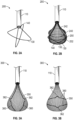
- an extraction device 1000 can include a plurality of rings 1020 that extend in a direction 1026 from a lumen 1012 of a delivery shaft 1010 to encapsulate a sample or specimen 1024 (e.g., some or all of a lens).
- Rings 1020 may, for example, be concentric wire rings that are pivotally bound at a joint 1022 at a distalmost end.
- rings 1020 have been deployed out of the lumen 1012 (e.g., by a manually or automatically controlled mechanism such as a push rod as described above in connection with FIGS. 5A and 5B ).
- rings 1020 may be folded within the distal end of lumen 1012. In this way, rings 1020 can be stored within shaft 1010 during insertion through an incision. As shown in FIG. 10C , rings 1020 may be rotated (e.g., in the direction of arrows 1030) relative to each other such that rings 1020 encapsulate and substantially surround sample 1024. FIG. 10D shows a top view of rings 1020 following rotation of the rings in directions as indicated by arrows 1030 to an encapsulated configuration.
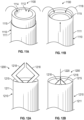
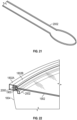
- an extraction device 1100 can include a shaft 1110 having an inner cylindrical shaft structure 1114 with a lumen 1112 and an outer shaft structure 1111 with a sharp cutting edge 1115 at a distalmost end thereof.
- cutting edge 1115 of outer shaft structure 1111 can be extended beyond the distalmost end of inner shaft structure 1114 to excise tissue. Suction can be provided that draws tissue excised by cutting edge 1115 into lumen 1112 as indicated by arrows 1118.
- an extraction device 1200 can include a shaft 1210 including an outer shaft structure 1211 with a sharp cutting edge 1115 at a distalmost end thereof.
- gripping structures such as forceps 1218 may be extended from within shaft 1210 to grip tissue to be excised.
- FIG. 12B as forceps 1218 are withdrawn into shaft 1210 in direction 1220, the tissue held by forceps 1218 can be cut free by cutting edge 1215.
- the forceps 1218 and/or suction can be provided that draws tissue excised by cutting edge 1215 into shaft 1210 for removal of the tissue.
- an extraction device 1300 can include a shaft 1310 having a lumen 1311 and an excision member that extends therefrom.
- the excision member may include a control shaft 1312 and one or more layered cutting and encapsulation leaves 1314.
- the excision member may have a concave scoop shape with a reduced profile for insertion through an incision.
- Layered cutting and encapsulation leaves 1314 may be reticulated relative to each other about an axis as indicated by arrows 1316 to create an enclosure for a lens or portion thereof as shown in the encapsulation configuration of FIG. 13B .
- one or more of leaves 1314 may have a cutting edge 1318 thereon that, when that leaf 1314 is rotated about the axis of, for example, shaft 1312, cuts through and excises the tissue to be encapsulated.
- edges of leaves 1314 may be blunt edges that slide between the lens and its surrounding tissue to encapsulate substantially the entire lens prior to removal.
- a cutting and/or suction mechanism can be applied within the encapsulated region formed by leaves 1314 (e.g., via an inner lumen of shaft 1312 into the encapsulated region to break up the encapsulated lens and suction out the broken up lens before re-stacking or re-layering leaves 1314 for withdrawal of device 1300.
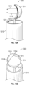
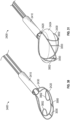
- an extraction device 1400 can include a shaft 1410 having a lumen 1413 with a partial lid structure 1414 for the lumen.
- Partial lid structure 1414 may include a sharp cutting edge 1415.
- partial lid 1414 extends perpendicularly to the axis of shaft 1410 to cover a portion of lumen 1413.
- forceps 1418 may be movably disposed within lumen 1413 for grasping or gripping of tissue.
- a twisting action may be performed to excise tissue using an axis that is off-center to the cutting edge 1415.
- forceps 1418 may be extended out of lumen 1413 by inner shaft 1412 to grasp tissue to be excised. The tissue may be grabbed, suctioned, and/or drawn into lumen 1413 (as indicated by arrow 1420 of FIG. 4C) and moved relative to the cutting edge 1415 to cause an excision.
- the tissue can be moved by fixing the cutting edge and rotating forceps 1418 (e.g., as indicated by arrow 1416 of FIGS. 4A and 4C) and/or by rotating shaft 1410 to rotate cutting edge 1415 relative to the tissue that is held by forceps 1418 (e.g., to reduce the potential of lens movement or rotation during excision that can damage the capsule).
- Grasping, suctioning, and/or rotating of tissue relative to cutting edge 1415 can be repeated to excise portions of a lens or other tissue until all of the desired tissue is removed.
- an extraction device 1500 can include a shaft 1510 having a lumen 1512 and a wire 1513 having a helical wire section 1520.
- Wire 1513 may be extendible from within the lumen 1512 at the distalmost end thereof.
- Shaft 1510 may include a sharp cutting edge 1515 at the distalmost end thereof.
- Wire 1513 may have a sharp piercing tip 1522 so that helical wire section 1520 can be rotated into a sample in a manner similar to a corkscrew to penetrate and grip the sample to be removed.
- a mesh cover or bag 1550 may be deployed from shaft 1510 (in a manner similar to the cover extension operations as discussed above in accordance with one or more embodiments) to encapsulate the sample to be removed.
- FIG. 15B shows a cross-sectional view of shaft 1510 showing how cutting edge 1515 may include an angled surface at the end of shaft 1510 relative to the axis of shaft 1510.
- shaft 1510 having cutting edge 1515
- shaft 1510 may be inserted into the anterior chamber of a patient's eye to deploy wire 1513 (e.g., a metallic wire as described herein) having piercing tip 1522 and a helical section 1520.
- wire 1513 e.g., a metallic wire as described herein
- Bag 1550 e.g., a silicone bag or other cover
- This extraction may cause edge 1515 to cut through the specimen to allow the specimen to enter into lumen 1512.
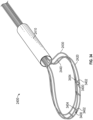
- an extraction device 1600 may include a shaft 1610 having an inner lumen from which a wire 1630 extends.
- Wire 1630 may be a deployable wire that is extendible from the distalmost end of shaft 1610 or may be permanently deployed.
- Wire 1630 may have a sliding side 1632 and a fixed side 1634.
- FIGS. 16A and 16B show device 1600 with a tip 1601 in a fully closed state ( FIG. 16A ), and an open state ( FIG. 16B ).
- Device 1600 may be a device for cataract extraction which is configured to enter the eye of a patient through a small incision in a somewhat cylindrical shape as in the configuration of FIG. 16A .
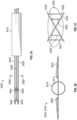
- device 1600 may have a tubular shaft 1610 which houses the cataract capturing components (labeled as segments 1630A, 1630B, and 1630F). Segments 1630A, 1630B, and 1630F may be fully retractable into tubular shaft 1610 (e.g., to make entering the eye easier), or may remain outside tubular shaft 1610 as depicted in FIG. 16A . Segments 1630A, 1630B, and 1630F may be joined at a hinge point 1639.
- tip 1601 of device 1600 may be forced to change shape by sliding segment 1630A to make it deform into a bow shape.
- This deformation may open the mouth of a basket formed to scoop up the lens.
- Segment 1630F may be fixed from moving in relation to segment 1630A.
- the length of the basket may extended by sliding segment 1630B (see, e.g., FIGS. 16C-16E ) in the same manner as segment 1630A, but in a different direction (e.g., 90 degrees different) from that of segment 1630A, causing segment 1630B to deform into a long bow shape.
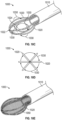
- segment 1600B may stretch open a bag or net-like cover structure 1650 as shown in FIGS. 16D and 16E .
- device 1600 may look somewhat like a butterfly net, which can be used to capture the lens to be removed. After capturing the lens, the entire assembly may be pulled down into tubular shaft 1610 to crush the lens enough to reduce the size, such that it can be withdrawn through the small incision in the eye.
- FIG. 16C shows device 1600 in a fully closed state, as seen in FIG. 16A from the side view.
- segment 1630A has been forced to deform such that the mouth 1640 of the basket opens.
- the configuration of FIG. 16D corresponds to that of FIG. 16B which shows, from the side, the bowed shape of segment 1630A, and how segment 1630A was slid up the tubular shaft while segment 1600F was held fixed in position.
- segments 1630A and B have been forced to deform such that the length 1642 of the basket 1644 is formed and the bag or net structure 1650 was deployed.
- an extraction device 1700 may include a first ring 1730 and a second ring 1740 that are extendible from a shaft 1710.
- Ring 1730 e.g., a metal ring such as a NiTi ring
- Second ring 1740 e.g., a metal ring such as a NiTi ring
- Second ring 1740 may be an open ring having an opening 1746 that is free of any film.
- shaft 1710 may form an inserter that can be inserted into an incision (e.g., a 2.75mm incision).
- an incision e.g., a 2.75mm incision
- the internal diameter of shaft 1710 may be 2.2 mm and the outer diameter of shaft 1710 may be 2.4 mm.
- Rings 1730 and 1740 may be deployed from the inserter behind a hydrodissected lens. Rings 1730 and 1740 may be opened up and separated from each other slightly (e.g., to a distance of 2mm apart).
- Rings 1730 and 1740 may be bridged by a film 1747 (e.g., PTFE film) with ring 1730 covered with, for example, PTFE 1745 and ring 1740 open (i.e., not covered by PTFE or other films).
- the lens may then be guided through the open ring 1740 to sit against the film 1745 that bridges the other ring 1730 (e.g., so that the natural lens is sitting in an open basket 1748 formed by rings 1730 and 1740 and films 1745 and 1747).
- the two rings can then be separated apart from each other by another 2mm so that the entire lens is in the "basket" 1748.
- a "lid" (not shown) to the basket may be slid over the open space 1746 in ring 1740.
- the lid e.g., formed by an additional ring with, e.g., PTFE covering
- the lid can slide in on small slots within ring 1740 for a smooth and controlled deployment of the lid.
- one or more additional rings e.g., 50 micron rings
- film 1745 is shows as a substantially planar film.
- a multi-ring scoop extraction device may be provided with a ring having a film that forms a basket shape.
- An example embodiment of a multi-ring scoop extraction device 1800 is shown in FIGS. 18-23 .
- an extraction device 1800 may include ring frames that are extendible from a lumen 1812 of a shaft 1810.
- extraction device 1800 includes a first (e.g., nitinol) frame 1802 that has a polymer or mesh bag 1804 attached thereto.
- Device 1800 may also include an additional (e.g., nitinol) frame 2002 (see, e.g., FIGS. 20 and 21 ) that can be deployed into and out of lumen 1812 independently of the first frame 1802.
- frame 2002 may be deployed when the initial bag/frame 1804/1802 component is deployed so that second frame 2002 sits just below frame 1802 as shown in the cross-sectional views of FIGS 20 and 22 .
- Device 1800 may also include a third frame 1900 (e.g., a nitinol frame) with a covering 1902 that forms a lid 1806 for basket 1804 when third frame 1900 is deployed.
- Covering 1902 may be a polymer or mesh covering or, in some embodiments, may contain relatively more rigid or solid material to provide additional strength and structure to frame 1900 for cutting of lens tissue as discussed in further detail hereinafter. In use, one or more of the following tasks may be performed.
- a capsulorhexis after a capsulorhexis has been performed and a lens of a patient's eye has been hydrodissected out of the natural position (e.g., so that the lens is sitting on the equator and partially in the iris plane), an introducer such as shaft 1810 may be inserted into the patient's eye (e.g., via an incision).
- an introducer such as shaft 1810 may be inserted into the patient's eye (e.g., via an incision).
- frame 1802 with bag 1804 and frame 2002 may be deployed into the anterior chamber of the eye.
- the lens may be approached and guided partially into the bag 1804 so that, for example, half the lens is in this artificial bag 1804.
- lid 1806 on frame 1900 may then be introduced such that lid 1806 and frame 1900 transect (e.g., bisect) the lens so that a portion (e.g., substantially half) of the lens is in encapsulated within a cavity defined by the bag 1804 and lid 1806 and a remaining portion (e.g., a remaining half) is outside of the cavity.
- frame 2002 that was introduced into the eye along with frame 1802 may be withdrawn or retracted from within the cavity into the lumen 1812 of the introducer 1810 to further segment the portion of the lens that is sitting in the cavity between artificial bag 1804 and lid 1806.
- the entire complex of all pieces in bag 1804 may then be retracted into the introducer 1810 to remove the portion of lens that is encapsulated therein. Introducer 1810 may then be removed from the eye and the segmented pieces are removed from the bag.
- the first through sixth tasks may be repeated for, for example, the other half lens that remains in the eye.
- the entirety of a lens may be encapsulated within the cavity, transected by one or more frames 2002, and removed by withdrawing frames 1802 and 1900 into introducer 1810 (e.g., without transecting the lens with lid frame 1900 while extending the lid frame 1900).
- lid frame 1900 may ride on an inside railing formed by a recess 2000 of the first frame 1802 (e.g., a recess in an inner portion 1802A of frame 1802 disposed interior to an outer frame portion 1802B) that contains the bag 1804.
- the leading end of the lid frame 1900 may be sharp so that frame 1900 can transect (e.g., bisect) the lens easily.
- lid frame 1900 may be formed from two or more frame segments to facilitate advancement of the lid.
- a segmented frame 1900 may be provided to allow for the lid frame 1900 to ride along the structure of the first frame 1802 with more precision (e.g., a bisected frame 1900 may ride on the rails of the first frame 1802 more easily than a monolithic frame).
- frame 2002 that is retracted after bagging the lens might be one of many such intermediate frames that are deployable and retractable such that the half lens that is bagged can be segmented multiple times with the multiple intermediate frames.
- a plurality of frames 2002 may be stacked on top or next to each other for independent deployment and retraction for cutting actions.
- frames 1802, 1900, and/or 2000 may be formed from nitinol or other metals or polymers in various embodiments.
- FIG. 23 shows a full cross-sectional perspective view of the cavity 2300 that is defined by and enclosed between bag 1804 and lid 1806 when deployed. Cavity 2300 may hold substantially half of a lens of a patient's eye as described herein for further dissection and removal.
- Bag 1804 and/or lid 1806 can contain elastic or inelastic polymer or mesh materials.
- Shaft 1810 (sometimes referred to as an introducer or an injector) may be composed of metal, polymer or glass materials.
- the distal end of the introducer in one or more embodiments, may contain flexible materials that expand when the bag is retracted back into the introducer.
- Shafts such as shaft 110 etc. described herein may be formed from sections of hypodermic tubing, sometimes referred to as a hypotube, according to some embodiments.
- bag 1804 and lid 1806 are shown in various examples as continuous sheets of material attached to their respective frames, this is merely illustrative. In some implementations, bag 1804 and/or lid 1806 may be provided with one or more openings (not explicitly shown). The openings may be cutouts from a continuous sheet implemented bag or lid or may be openings in mesh sheets attached to the respective frames that form bag 1804 and/or lid 1806.
- frames 1802 and/or 1900 may be withdrawn into delivery shaft 1810 such that parts of the secured lens (or portion thereof) are forced to exit the bag and/or lid through the openings into the anterior chamber as the bag and/or lid is being withdrawn into the distal end of the tube.
- bag 1804 and/or lid 1806 may be configured to act as a strainer for the lens (or portion thereof) that, upon withdrawal of frames 1802 and/or 1900 into the distal end of delivery shaft 1810, cause some or all of the lens come out through the openings as a ground or strained material that can be later removed (e.g., via suction) from the anterior chamber.
- a method of removing some or all of the lens of a patient's eye may include extending a first frame (e.g., frame 1802) having an attached flexible bag structure (e.g., bag 1804) with a plurality of openings from a distal end of a delivery shaft (e.g., shaft 1810) into an anterior chamber of an eye of a patient such that the flexible bag structure at least partially surrounds at least a portion of a lens of the eye of the patient; extending a second frame (e.g., frame 1900) having an attached lid structure (e.g., lid 1806) along the first frame to secure the at least the portion of the lens between the flexible bag structure and the lid structure; and withdrawing the first and second frames into the distal end of the delivery shaft to strain the at least the portion of the lens through the plurality of openings in the flexible bag structure into the anterior chamber.
- a first frame e.g., frame 1802
- an attached flexible bag structure e.g., bag 1804
- the method may also include suctioning the strained at least the portion of the lens from the anterior chamber, in one or more embodiments.
- an extraction device 2400 can include a delivery shaft 2410 having a lumen 2413 and a distal end 2415 from which one or more wires can extend.
- extraction device 2400 may be implemented as a three-wire snare having first wire 2420, second wire 2430, and third wire 2440.
- First wire 2420, second wire 2430, and third wire 2440 may each be a wire loop formed from metal (e.g., nitinol), plastic, and/or a shape memory material.
- First wire 2420, second wire 2430, and third wire 2440 may be extended from distal end 2415 of delivery shaft 2410 and positioned to lasso or surround lens 2424 (e.g., within the eye following hydrodissection or hydrodelineation of the lens). Once first wire 2420, second wire 2430, and third wire 2440 are positioned around the lens as shown in FIG. 24 , first wire 2420, second wire 2430, and third wire 2440 can be retracted back into lumen 2413 of delivery shaft 2410 (e.g., in direction 2442).
- first wire 2420, second wire 2430, and third wire 2440 may be pulled through lens 2424 to split lens 2424 into four pieces 2426, 2428, 2430, and 2432.
- the four pieces 2426, 2428, 2432, and 2434 of lens 2424 may then each be removed from the eye (e.g., with a forceps that grabs and/or crushes the lens piece).
- first wire 2420, second wire 2430, and third wire 2440 when first wire 2420, second wire 2430, and third wire 2440 are in an extended position with respect to distal end 2415 of delivery shaft 2410, first wire 2420, second wire 2430, and third wire 2440 may be positioned such that the distance between each wire increases with increasing distance from distal end 2415 (e.g., from a first distance D1 near distal end 2215 of shaft 2410 to a second distance D2 that is greater than D1 near a distalmost end of the wire loops). First wire 2420, second wire 2430, and third wire 2440 may be positioned together within lumen 2413 and then separated during or after extension from lumen 2413.
- delivery shaft 2410 may include one or more features such as feature 2450 (e.g., an integral or attached extension from the inner surface of delivery shaft 2410 in lumen 2413) that causes first wire 2420, second wire 2430, and third wire 2440 to separate from each other as they are extended from distal end 2415 (e.g., as adjacent wires slide along opposing sides of feature 2450).
- feature 2450 may be a protrusion extending from an inner surface of the delivery shaft in the lumen that causes the first, second, and third wire loops to separate upon extension from within the lumen.
- one or more slidable separators 2451 may be actuated within or extended from lumen 2413 between adjacent wires to cause the adjacent wires to separate into the position shown in FIG. 24 .
- Slidable separator 2451 may be moved between at least two of the first, second, and third wire loops to separate the at least two of the first, second, and third wire loops.
- first wire 2420, second wire 2430, and third wire 2440 may be heat set wires such as nitinol heat set wires that are conditioned to separate after being extended a predetermined distance from within lumen 2413.
- first, second, and third wire loops 2420, 2430, and 2430 may be heat set wire loops configured to self separate upon extension to a predetermined distance from the distal end of the delivery shaft.
- first wire 2420, second wire 2430, and third wire 2440 may be extended from lumen 2413 at the same time or at different times (e.g., using a common extension mechanism or separate extension mechanisms to push the wires out of the lumen).
- FIG. 25 shows a side view of device 2400 with the wires extending around lens 2424. It should be appreciated that, although wires 2420, 2430, and 2440 have been referred to as a first wire, a second wire, and a third wire, this is merely for convenience and any of wires 2420, 2430, and 2440 can be referred to as a first wire, a second wire, or a third wire (or wire loop).
- FIG. 26 shows a broader view of extraction device 2400 in which delivery shaft 2410 can be seen extending from a handle 2500 of device 2400.
- delivery shaft 2410 may be a substantially cylindrical tube attached at a proximal end to handle 2500.
- Handle 2500 may include a slider tab 2502, moveable by a user within a groove 2504, for deployment and retraction of wires 2420, 2430, and 2440 from delivery shaft 2410.
- Slider tab 2502 may be coupled to wires 2420, 2430, and 2440 such that sliding slider tab 2502 away from shaft 2410 pulls wires 2420, 2430, and 2440 back into shaft 2410.
- slider tab 2502 Although a single slider tab 2502 is shown in FIG. 26 , it should be appreciated that two, three, or more sliders may be provided that slide in parallel within groove 2504 to move wires 2420, 2430, and 2440 and/or one or more separators or encapsulating bags individually or in groups. Actuation of sliders such as slider tab 2502 can control, together or separately, wires 2420, 2430, and 2440 and/or other components to deploy, retract, and/or rotate the wires and/or components attached thereto.
- the cross section of the slider mechanism within groove 2504 (and coupled to slider tab 2502) can be various shapes including circular (e.g., one tube within another which allows for rotational motion in addition to translational motion, see FIGS. 28 and 29 as examples).
- One or more slider tabs such as slider tab 2502 may each be attached to one or both ends of the wire loops that form wires 2420, 2430, and 2440.
- one end of each wire loop may be fixed within shaft 2410 and an opposing end attached to a slider tab so that extending the wire from lumen 2413 is performed by moving one side of the wire out of the lumen while the other side remains fixed.
- both ends of each wire loop may be attached to a slider tab so that extending the wire from lumen 2413 is performed by moving the entire loop.
- Wires 2420, 2430, and 2440 may be manipulated around lens 2424 together, prior to separation, or may be sequentially manipulated around lens 2424 after separation.
- FIG. 27 shows a perspective view of extraction device 2400 in which a control mechanism 2700 is provided at an end of handle 2500 opposite to the end at which delivery shaft 2410 is attached.
- control mechanism 2700 includes a handle 2704 coupled to a threaded shaft 2702.
- handle 2704 may be rotated to move shaft 2410 (coupled to delivery shaft 2410 within handle 2500) to control the distance to which shaft 2410 extends from handle 2500.
- control mechanism 2700 may also allow for wires 2420, 2430, and 2440 to be removed from shaft 2410 and handle 2500 so that another tool such as a forceps can be inserted to remove cut portions of lens 2424 from the patient's eye via lumen 2413.
- a forceps may be included within delivery shaft 2410 and separately operable from wires 2420, 2430, and 2440.
- forceps separate from extraction device 2400 may be used to extract lens pieces from the eye after the lens has been cut by wires 2420, 2430, and 2440.
- additional elements such as a mesh or stent, and an encapsulation bag may be used in combination with wire loops 2420, 2430, and 2440 for extraction of lens pieces.
- wires 2420, 2430, and 2440 are shown to be linearly separated in the implementation shown in FIGS. 24-27 , this is merely illustrative and other implementations of wires 2420, 2430, and 2440 are possible.
- FIGS. 28 and 29 show an implementation of extraction device 2400 in which wires 2420, 2430, and 2440 are rotatable relative to one another to surround and dissect lens 2424.
- FIGS. 28 and 29 show extraction device 2400 without delivery shaft 2410 for clarity.
- wires 2420, 2430, and 2440 may be extended around lens 2424 together in a flattened, substantially planar common loop.
- device 2400 is provided with wire-guide structures 2800, 2802, and 2804 (e.g., substantially cylindrical nested wire guide structures that are slidable and/or rotatable within delivery shaft 2410) configured to rotate wires 2420, 2430, and 2440 relative to each other to substantially surround lens 2424 (e.g., as in the configuration of FIG. 29 ).
- Wire-guide structure 2800 may include a cylindrical main body 2806 (e.g., a portion of shaft 2410) and one or more protrusions 2808 (e.g., on the inner surface of shaft 2410 or on an outer surface of structure 2810) that guide the position of wire 2420.
- a portion of wire 2420 may be positioned between two of protrusions 2808 and between the outer surface of cylindrical main body 2810 and the inner surface of delivery shaft 2410 so that the position of wire 2420 can be controlled by protrusions 2808.
- Wire-guide structure 2802 may include a cylindrical main body 2810 that is at least partially nested within cylindrical main body 2806 of wire-guide structure 2800.
- Wire-guide structure 2802 may include a notch 2812 that allows wire 2440 to pass into an internal recess within wire-guide structure 2802 so that the rotational position of wire 2440 can be controlled by rotation of wire-guide structure 2802 (e.g., relative to wire-guide structures 2800 and 2804).
- Wire-guide structure 2804 may include a cylindrical main body 2814 that is at least partially nested within cylindrical main body 2810 of wire-guide structure 2802.
- Wire-guide structure 2804 may include a notch 2816 that allows wire 2430 to pass into an internal recess within wire-guide structure 2804 so that the rotational position of wire 2430 can be controlled by rotation of wire-guide structure 2804 (e.g., relative to wire-guide structures 2800 and 2802).
- first, second, and third wire loops 2420, 2440, and 2430 are configured to separate by a rotation of second and third wire loops 2440 and 2430 relative to first wire loop 2420.
- Wire-guide structures 2800, 2802, and 2804 may include first, second, and third nested wire-guide structures and configured to control a rotational position of first, second, and third wire loops 2420, 2440, and 2430.
- First wire-guide structure 2800 may include a cylindrical main body 2806 (e.g., a portion of shaft 2410) and a plurality of protrusions 2808 on an outer surface of the cylindrical main body 2810 or on an inner surface of shaft 2410.
- Second wire-guide structure 2802 may include a cylindrical main body 2810 at least partially nested within the cylindrical main body 2806 of first wire-guide structure 2800 (e.g., within shaft 2410) and at least one slot 2812 for the second wire loop 2440.
- Third wire-guide structure 2804 may include a cylindrical main body 2814 at least partially nested within the cylindrical main body 2810 of the second wire-guide structure and at least one slot 2816 for the third wire loop 2430.
- Second and third wire-guide structures 2802 and 2804 are rotatable relative to first wire-guide structure 2800.
- First, second, and third wire-guide structures 2800, 2802, and 2804 are slidable within delivery shaft 2410 for extension and retraction of the first, second, and third wire loops 2420, 2440, and 2430.
- wire-guide structures 2802 and 2804 may be rotated relative to wire-guide structure 2800 so that one or more wire loops 2420, 2430, and 2440 are rotated to surround the lens.
- wires 2420, 2430, and 2440 can be retracted into delivery shaft 2410 to dissect the lens into multiple pieces as the wires are retracted. The dissected lens pieces can then be removed from the eye using forceps.
- FIGS. 30 and 31 show an implementation of extraction device 2400 in which two wires 2420 and 2430 are provided with interconnecting wires 3000 and 3002 that couple wires 2420 and 2430 at various locations around the respective wire loops.
- FIGS. 30 and 31 show an implementation of extraction device 2400 in which two wires 2420 and 2430 are provided with interconnecting wires 3000 and 3002 that couple wires 2420 and 2430 at various locations around the respective wire loops.
- interconnecting wires 3000 extend between wire loops 2420 and 2430 near a distal end of the loops and two relatively longer interconnecting wires 3002 extend between wire loops 2420 and 2430 nearer the distal end of delivery shaft 2410.
- interconnecting wires 3000 and 3002 may be extended from a relaxed shape (as shown in FIG. 30 ) to a more straight and tensioned shape (as shown in FIG. 31 ), and thereby form a net-like structure which may surround lens 2424.
- First and second wire loops 2420 and 2430 in the implementation of FIGS. 30 and 31 are configured to separate by a rotation of first and/or second wire loops.
- Wire-guide structures such as wire-guide structures 2800 and 2802 may be provided within delivery shaft 2410 to control the relative rotation of wire loops 2420 and 2430.
- wires 2420 and 2430 and interconnecting wires 3000 and 3002 can be retracted into delivery shaft 2410 to dissect the lens into multiple pieces as the wires are retracted and wires 2420 and 2430 and interconnecting wires 3000 and 3002 cut through lens 2424.
- the dissected lens pieces can then be removed from the eye using forceps or other structures such as a wire mesh or stent and/or an encapsulation bag.
- FIGS. 32 and 33 show an implementation of extraction device 2400 in which two linearly separable wires 2420 and 2430 are provided with interconnecting wires 3000 that couple wires 2420 and 2430 at various locations around the respective wire loops.
- interconnecting wires 3000 of substantially equal length extend between wire loops 2420 and 2430 at various locations around the loops.
- interconnecting wires 3000 may be extended from a relaxed shape (as shown in FIG. 32 ) to a more straight and tensioned shape (as shown in FIG. 33 ), and thereby form a net-like structure which may surround lens 2424.
- First and second wire loops 2420 and 2430 in the configuration of FIGS. 31 and 32 may be configured to linearly separate to a separated configuration in which first wire loop 2420 is substantially parallel to second wire loop 2430 or in which wire loops 2420 and 2430 are separated by an increasing distance with increasing distance from shaft 2410 (see, e.g., FIG. 24 ).
- wires 2420 and 2430 and interconnecting wires 3000 can be retracted into delivery shaft 2410 to dissect the lens into multiple pieces as the wires are retracted and wires 2420 and 2430 and interconnecting wires 3000 cut through lens 2424.
- the dissected lens pieces can then be removed from the eye using forceps or other components such as a wire mesh and/or an encapsulation bag.
- FIGS. 34 and 35 show an implementation of extraction device 2400 in which three linearly separable wires 2420, 2430, and 2440 are provided with interconnecting wires 3400 that couple wires 2420, 2430, and 2440 at various locations around the respective wire loops.
- interconnecting wires 3400 of substantially equal length extend between wire loops 2420, 2430, and 2440 at various locations around the loops.
- Each interconnecting wire includes a first portion 3402 that extends from wire 2420 to wire 2430 and a second portion 3404 that extends from wire 2430 to wire 2440.
- portions 3402 and 3404 are located at the same location on the loops. However, portions 3402 and 3404 may be located at different locations around the loops in some implementations.
- FIG. 35 shows a side view of the implementation of device 2400 of FIG. 34 in which it can be seen that, prior to separation of wire loops 2420, 2430, and 2440, middle loop 2430 is initially deployed from delivery shaft 2410 with a smaller diameter than the top and bottom loops 2420 and 2430, which causes the group of loops 2420, 2430, and 2440 to lay flat by tensioning the interconnecting wires 3400, and thus pulling the top and bottom loops 2420 and 2440 toward the middle loop 2430.
- Middle loop 2430 can then be pushed outward from delivery shaft 2410, such that the diameter of middle loop 2430 is increased to the same diameter as that of top and bottom loops 2420 and 2430, causing interconnecting wires 3400 to straighten, pushing wire loops 2420 and 2440 apart (e.g., as indicated by arrows 3500).
- wire loops 2420, 2430, and 2440 can be moved to surround lens 2424.
- Wire loops 2420, 2430, and 2440 can then be expanded or separated by extending middle loop 2430 as described, such that interconnecting wires 3400 stand roughly perpendicular to the main loops 2420, 2430, and 2440.
- Wire loops 2420, 2430, and 2440 can then be retracted into delivery shaft 2410 to cut the lens into multiple pieces as wires 2420, 2430, and 2440 and interconnecting wires 3400 pass through the lens.
- the dissected lens pieces can then be removed from the eye using forceps or other components such as a wire mesh and/or an encapsulation bag.
- FIGS. 36-40 face-on views of various implementations of extraction device 2400 (e.g. views facing the distalmost end of device 2400 along the central longitudinal axis of device 2400) are shown in FIGS. 36-40 . More specifically, FIGS. 36 and 37 show face-on views of device 2400 in the implementation of FIGS. 30 and 31 , FIGS. 38 and 39 show face-on views of device 2400 in the implementation of FIGS. 32 and 33 , and FIG. 40 shows a face-on view of device 2400 in the implementation of FIGS. 34 and 35 .
- FIG. 36 shows a face-on view of device 2400 in the implementation and in the flattened configuration of FIG. 30 , and shows how interconnecting wires 3002 may be curved slightly out of a plane defined by non-rotated wires 2420 and 2430 in the flattened configuration.
- FIG. 37 shows a face-on view of device 2400 in the implementation and rotated configuration of FIG. 31 and shows how interconnecting wires 3000 and 3002 may be straightened by rotated wires 2420 and 2430 that form an x-pattern in the rotated configuration.
- FIG. 38 shows a face-on view of device 2400 in the implementation and flattened-configuration of FIG. 32 .
- interconnecting wires 3200 may be straightened so that, as shown in FIG. 39 , wires 2420 and 2430 may be substantially parallel with substantially perpendicular interconnecting wires 3200 interposed between.
- FIG. 40 shows a face-on view of device 2400 in the implementation and flattened-configuration of FIGS. 34 and 35 .
- interconnecting wires 3400 may be straightened wires 2420, 2430, and 2440 may be substantially parallel with substantially perpendicular interconnecting wires 3400 interposed between.
- extraction device 2400 may be used to dissect lens 2424 into pieces (e.g., roughly equal sized pieces in the example of FIGS. 34 , 35 , and 40 ) that individually are sized to fit down delivery shaft 2410 for extraction.
- extraction device 2400 may include one or more other components, in addition to one, two, three, or more cutting wires, such as a wire mesh or stent (e.g., to further dissect the cut lens pieces) and/or an encapsulation bag, extendible over the wires and/or the stent to encapsulate the cut/dissected lens for extraction through delivery shaft 2410.
- the wire mesh or stent can be used in place of, or in addition to, the cutting wires as described in connection with the implementations shown FIGS. 24-40 .
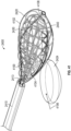
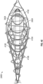
- FIG. 41 shows an exemplary implementation of extraction device 2400 in which a stent 4100 and an encapsulation bag 4102 are provided in addition to wire loops 2420, 2430, and 2440.
- a wire mesh or stent such as stent 4100 may be extended around wire loops 2420, 2430, and 2440.
- Encapsulation bag 4102 may be extended around stent 4100 (e.g., as described above in connection with various implementations).
- An opening 4104 may be provided (e.g., an opening formed by coaligned openings in bag 4102 and stent 4100) through which lens 2424 can be inserted into a cavity formed and defined by stent 4100 and bag 4102.
- lens 2424 can be inserted through opening 4104 into the cavity and substantially surrounded by wires 2420, 2430, and 2440, stent 4100, and bag 4102.
- FIG. 42 shows a side view of extraction device 2400 in the configuration of FIG. 41 after insertion of lens 2424 into the cavity formed by wires 2420, 2430, and 2440, stent 4100, and bag 4102.
- wires 2420, 2430, and 2440 may be retracted into lumen 2413 to cut lens 2424 (e.g., as described above in connection with FIGS. 24 and 25 ), and then stent 4100 may be retracted to further cut and/or cube the lens into smaller, softer pieces.
- Device 2400 may also include a spiral compaction wire 4108 wrapped in spiral windings around bag 4102. After wires 2420, 2430, and 2440 and stent 4100 have been retracted to cut and cube lens 2424 within bag 4102, spiral compaction wire 4108 may be retracted to further compact the pieces of lens 2424 within encapsulation bag 4102 for extraction from the eye (e.g., by extracting bag 4102 and wire 4108 into lumen 2413 or by withdrawing device 2400 from the eye without extracting bag 4102 back into lumen 2413).
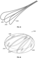
- FIG. 43 shows wires 2420, 2430, and 2440 of device 2400 of FIG. 41 with other components of device 2400 removed for clarity.
- Wires 2420, 2430, and 2440 may be formed, for example, from nitinol, may have a cross-sectional width of, for example, 0.004", and may be extended and/or withdrawn from lumen 2413 as described above in connection with, for example FIGS. 24-27 .
- FIG. 44 shows an illustrative example of a lens 2424 that has been cut into pieces 2426, 2428, 2432, and 2434 by retraction of wires 2420, 2430, and 2440 through lens 2424 into lumen 2413.
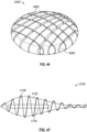
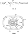
- FIG. 45 shows stent 4100 of device 2400 of FIG. 41 with other components of device 2400 removed for clarity.
- Stent 4100 may include a plurality of intersecting wire elements 4502 extending from a shaft 4500 that form and define a cavity 4503.
- Stent 4100 may be formed from a wire mesh braid or may be a laser-cut structure.
- Intersecting wire elements 4502 may be formed from metal and/or plastic and may have a cross-sectional width of between 0.001" and 0.005" (e.g., 0.003 inches) in some implementations.
- Intersecting wire elements 4502 may be configured to return to a natural expanded shape, as shown in FIG.
- FIG. 46 shows an illustrative example of a lens 2424 in which pieces 2426, 2428, 2432, and 2434 have been cut/cubed into smaller pieces 4600 by retraction and resulting compression of stent 4100 through lens 2424 into lumen 2413.
- FIG. 47 shows encapsulation bag 4102 and spiral compaction wire 4108 of device 2400 of FIG. 41 with other components of device 2400 removed for clarity.
- Encapsulation bag 4102 may be formed from an elastic material such as an expanded polytetrafluoroethylene (ePTFE) material.
- Encapsulation bag 4102 may include an opening 4704. Opening 4704 may be configured to be coaligned with opening 4504 of stent 4100, when stent 4100 and bag 4102 are in an extended configuration, to form opening 4104 of FIG. 41 .
- Spiral compaction wire 4108 may be formed from a metal such as nitinol and may have a cross-sectional width of, for example, between, 0.001" and 0.005" (e.g., 0.003").
- Spiral compaction wire 4108 may be extracted to radially compress encapsulation bag 4102, in a circular motion, into the configuration of FIG. 48 , to collect and compress pieces 4600 of lens 2424 for extraction from the eye.
- Encapsulation bag 4102 can be removed from the patient's eye by retraction into lumen 2413 or by extraction of the entire device 2400 from the eye without pulling bag 4102 back into lumen 2413.
- some pieces of lens 2424 may also occupy some of the space within lumen 2413 (e.g., by being pulled into delivery shaft 2410 during the retraction).
- a phrase such as "an aspect” does not imply that such aspect is essential to the subject technology or that such aspect applies to all configurations of the subject technology.
- a disclosure relating to an aspect may apply to all configurations, or one or more configurations.
- An aspect may provide one or more examples of the disclosure.
- a phrase such as “an aspect” may refer to one or more aspects and vice versa.
- a phrase such as “an embodiment” does not imply that such embodiment is essential to the subject technology or that such embodiment applies to all configurations of the subject technology.
- a disclosure relating to an embodiment may apply to all embodiments, or one or more embodiments.
- An embodiment may provide one or more examples of the disclosure.
- a phrase such "an embodiment” may refer to one or more embodiments and vice versa.
- the phrase "at least one of' preceding a series of items, with the term “and” or “or” to separate any of the items, modifies the list as a whole, rather than each member of the list (i.e., each item).
- the phrase "at least one of” does not require selection of at least one of each item listed; rather, the phrase allows a meaning that includes at least one of any one of the items, and/or at least one of any combination of the items, and/or at least one of each of the items.
- phrases “at least one of A, B, and C” or “at least one of A, B, or C” each refer to only A, only B, or only C; any combination of A, B, and C; and/or at least one of each of A, B, and C.
- top should be understood as referring to an arbitrary frame of reference, rather than to the ordinary gravitational frame of reference.
- a top surface, a bottom surface, a front surface, and a rear surface may extend upwardly, downwardly, diagonally, or horizontally in a gravitational frame of reference.
Landscapes
- Health & Medical Sciences (AREA)
- Surgery (AREA)
- Life Sciences & Earth Sciences (AREA)
- Public Health (AREA)
- Animal Behavior & Ethology (AREA)
- Engineering & Computer Science (AREA)
- Biomedical Technology (AREA)
- Heart & Thoracic Surgery (AREA)
- Veterinary Medicine (AREA)
- General Health & Medical Sciences (AREA)
- Nuclear Medicine, Radiotherapy & Molecular Imaging (AREA)
- Ophthalmology & Optometry (AREA)
- Molecular Biology (AREA)
- Medical Informatics (AREA)
- Vascular Medicine (AREA)
- Orthopedic Medicine & Surgery (AREA)
- Prostheses (AREA)
- Endoscopes (AREA)
Description
- The present disclosure generally relates to surgical devices and, in particular, relates to cataract extraction devices.
- Cataracts often cause loss of vision by clouding the lens of the eye. Cataract surgery is often performed, in which the lens is removed from the eye and replaced with a synthetic lens. However, if care is not taken, it can be difficult to remove the lens without creating a large incision or without breaking the lens into an uncontrollable number of small pieces.
-
US 2013/211415 A1 discloses a medical device comprising a tubular member having a proximal end, a distal end, and a lumen extending between the proximal end and the distal end, and an elongate member having a proximal end and a distal end, wherein at least a portion of the elongate member is movably disposed within the lumen of the tubular member, wherein the distal end of the elongate member includes an end-effector, wherein a portion of the elongate member between the proximal end and the distal end is configured to transition from a first state to a second state when the portion is advanced out of the lumen of the tubular member, and wherein the portion is proximal of the end-effector -
US 5 891 153 A discloses a surgical instrument for removing the cataractous nucleus from the eye. The instrument consists of a proximal handle and plunger. The plunger also acts as a screw-drive for an auger located at the distal end of the instrument. The screw-drive plunger is advanced exposing a nucleus encasing basket at the distal end of the instrument. The nucleus is completely encased in the distal basket and slowly ground up by the auger, removing the nucleus from the eye in its entirety. The use of unique internal gearing between the auger and encasing element results in a safe, efficient, controllable evacuation of the nucleus from the eye. -
US 2007/0116225 A1 describes a surgical instrument assembly for use in retrieving objects from internal body cavities. It has a net element slidably attached to the outer loop and preferably fixed to the outer loop at a distal point. - The invention is defined by the claims. In the following, parts of the description and drawings referring to embodiments which are not covered by the claims are not presented as embodiments of the invention, but as examples useful for understanding the invention.
- A handheld device, sometimes referred to herein as a cataract extraction device or an extraction device, is provided that can be used to break the lens of the eye of a patient into a desired number of pieces and remove the resulting pieces from the eye through an incision. For example, after a hydrodissection of the lens has been performed to displace the lens from its capsule, the extraction device can be moved into the eye through a corneal incision and be utilized to encapsulate or partially surround the lens and remove it in a controlled manner in one or more pieces. A second device can be used to flush the eye of any lens remnants.
- The extraction device may include additional mechanisms or components to control the motion of lens elements out of the anterior chamber of the eye. The devices can be provided together as a kit. In some embodiments, the extraction device can contain at least a part of the lens during and/or after hydrodissection. If the lens is undesirably displaced during hydrodissection, the device can be used to recapture the lens or a portion thereof.
- In accordance with certain aspects, an extraction device is provided that includes a delivery shaft having a lumen and a distal end. The extraction device also includes a first wire forming a first arc and being positionable distal to the distal end of the delivery shaft while ends of the first arc are at a distalmost end of the delivery shaft. The extraction device also includes a second wire forming a second arc and being positionable distal to the distal end of the delivery shaft while ends of the second arc are at the distalmost end of the delivery shaft. A distalmost extent of the first wire is distal to a distalmost extent of the second wire, and the first wire and the second wire are separately retractable relative to the delivery shaft.
- In accordance with other aspects, an extraction device is provided that includes a delivery shaft having a lumen and a distal end. The extraction device also includes a dissection tool distal to the distal end of the delivery shaft. The extraction device also includes a first capture portion positionable on a first side of an axis of the delivery shaft and comprising a first cover. The extraction device also includes a second capture portion positionable on a second side of the axis, opposite the first side, and comprising a second cover. The first capture portion and the second capture portion are configured to move toward the axis upon actuation and define an enclosed space between the first cover and the second cover.
- In accordance with other aspects, an extraction device is provided that includes a delivery shaft having a distal end. The extraction device also includes an irrigation port at the distal end. The extraction device also includes a loop having a fluid permeable cover. The extraction device also includes a blade being moveable from a retracted position to an actuated position across at least a portion of the loop.
- In accordance with other aspects, an extraction device is provided that includes a delivery shaft having an inner cylindrical shaft structure with a distal end. The delivery shaft also includes an outer cylindrical shaft structure having a distal end with a sharp cutting edge. The sharp cutting edge of the outer cylindrical shaft structure is deployable beyond the distal end of the inner cylindrical shaft structure.
- In accordance with other aspects, an extraction device is provided that includes a delivery shaft having a distal end with a sharp cutting edge. The extraction device also includes a gripping apparatus that is extendible from within a lumen of the delivery shaft and operable to grip and pull tissue against the sharp cutting edge.
- In accordance with other aspects, an extraction device is provided that includes a delivery shaft having a distal end. The extraction device also includes an excision member that is extendible from within a lumen of the delivery shaft. The excision member includes a control shaft and a plurality of layered cutting and encapsulation leaves.
- In accordance with other aspects, an extraction device is provided that includes a delivery shaft having a distal end. The extraction device also includes a first frame extendible from the distal end of the delivery shaft and having a flexible bag structure attached thereto. The extraction device also includes a second frame extendible from the distal end of the delivery shaft and having a lid structure attached thereto. In an extended configuration for the first frame and the second frame, the flexible bag structure and the lid structure are configured to define and enclose a cavity within which at least a portion of a lens of a patient's eye is encapsulated.
- As illustration a method is described that includes extending a first frame, having an attached flexible bag structure, and a second frame into an eye of a patient such that the flexible bag structure at least partially surrounds at least a portion of a lens of the eye of the patient. The method also includes extending a third frame having an attached lid structure along the first frame to encapsulate the at least the portion of the lens between the flexible bag structure and the lid structure. The method also includes withdrawing the second frame to transect the encapsulated at least the portion of the lens.
- In accordance with other aspects, an extraction device is provided that includes a delivery shaft having a distal end. The extraction device also includes a first frame extendible from the distal end of the delivery shaft and having a flexible bag structure attached thereto. The flexible bag structure includes a plurality of openings. The extraction device also includes a second frame extendible from the distal end of the delivery shaft and having a lid structure attached thereto. In an extended configuration for the first frame and the second frame, the flexible bag structure and the lid structure are configured to secure at least a portion of a lens of a patient's eye therebetween.
- As illustration a method is described that includes extending a first frame having an attached flexible bag structure with a plurality of openings from a distal end of a delivery shaft into an anterior chamber of an eye of a patient such that the flexible bag structure at least partially surrounds at least a portion of a lens of the eye of the patient. The method also includes extending a second frame having an attached lid structure along the first frame to secure the at least the portion of the lens between the flexible bag structure and the lid structure. The method also includes withdrawing the first and second frames into the distal end of the delivery shaft to strain the at least the portion of the lens through the plurality of openings in the flexible bag structure into the anterior chamber.
- In accordance with other aspects, an extraction device is provided that includes a delivery shaft having a lumen and a distal end. The extraction device also includes first, second, and third wire loops extendible from within the lumen at the distal end, wherein the first, second, and third wire loops are configured to separate upon extension from within the lumen to at least partially surround a lens of a patient's eye, and wherein the separated first, second, and third wire loops are configured to be withdrawn into the lumen to pass through and dissect the lens.
- In accordance with other aspects, an extraction device is provided that includes a delivery shaft having a lumen and a distal end. The extraction device also includes first and second wire loops extendible from within the lumen at the distal end. The extraction device also includes a plurality of interconnecting wires that extend from the first wire loop to the second wire loop. The first and second wire loops are configured to separate upon extension from within the lumen to at least partially surround a lens of a patient's eye, and the separated first and second wire loops and the plurality of interconnecting wires are configured to be withdrawn into the lumen to pass through and dissect the lens.
- In accordance with other aspects, an extraction device is provided that includes a delivery shaft having a lumen and a distal end. The extraction device also includes first, second, and third wire loops extendible from within the lumen at the distal end, wherein the first, second, and third wire loops are configured to separate upon extension from within the lumen and are maneuverable to at least partially surround a lens of a patient's eye. The extraction device also includes a stent extendible from within the lumen around the extended first, second, and third wire loops. The extraction device also includes an encapsulation bag extendible from within the lumen around the extended stent and the extended first, second, and third wire loops.
- Additional features and advantages of the subject technology will be set forth in the description below, and in part will be apparent from the description, or may be learned by practice of the subject technology. The advantages of the subject technology will be realized and attained by the structure particularly pointed out in the written description and claims hereof as well as the appended drawings.
- It is to be understood that both the foregoing general description and the following detailed description are exemplary and explanatory and are intended to provide further explanation of the subject technology as claimed.
- The accompanying drawings, which are included to provide further understanding of the subject technology and are incorporated in and constitute a part of this description, illustrate aspects of the subject technology and, together with the specification, serve to explain principles of the subject technology.
-
FIG. 1A shows a perspective view of an extraction device, in accordance with one or more embodiments of the present disclosure. -
FIG. 1B shows a perspective view of the extraction device ofFIG. 1A , in accordance with one or more embodiments of the present disclosure. -
FIG. 1C shows a perspective view of the extraction device ofFIG. 1A , in accordance with one or more embodiments of the present disclosure. -
FIG. 1D shows a perspective view of the extraction device ofFIG. 1A , in accordance with one or more embodiments of the present disclosure. -
FIG. 1E shows a perspective view of the extraction device ofFIG. 1A , in accordance with one or more embodiments of the present disclosure. -
FIG. 1F shows a perspective view of the extraction device ofFIG. 1A , in accordance with one or more embodiments of the present disclosure. -
FIG. 1G shows a perspective view of the extraction device ofFIG. 1A , in accordance with one or more embodiments of the present disclosure. -
FIG. 2A shows a perspective view of an extraction device, in accordance with one or more embodiments of the present disclosure. -
FIG. 2B shows a perspective view of the extraction device ofFIG. 2A , in accordance with one or more embodiments of the present disclosure. -
FIG. 3A shows a perspective view of an extraction device, in accordance with one or more embodiments of the present disclosure. -
FIG. 3B shows a perspective view of an extraction device, in accordance with one or more embodiments of the present disclosure. -
FIG. 4 shows a perspective view of an extraction device, in accordance with one or more embodiments of the present disclosure. -
FIG. 5A shows a perspective view of an interface tool, in accordance with one or more embodiments of the present disclosure. -
FIG. 5B shows a perspective view of the interface tool ofFIG. 5A , in accordance with one or more embodiments of the present disclosure. -
FIG. 6A shows a perspective view of an extraction device, in accordance with one or more embodiments of the present disclosure. -
FIG. 6B shows a perspective view of the extraction device ofFIG. 6A , in accordance with one or more embodiments of the present disclosure. -
FIG. 7 shows a perspective view of an extraction device, in accordance with one or more embodiments of the present disclosure. -
FIG. 8 shows a perspective view of an extraction device, in accordance with one or more embodiments of the present disclosure. -
FIG. 9 shows a perspective view of an extraction device, in accordance with one or more embodiments of the present disclosure. -
FIG. 10A shows a perspective view of an extraction device, in accordance with one or more embodiments of the present disclosure. -
FIG. 10B shows a perspective view the extraction device ofFIG. 10A , in accordance with one or more embodiments of the present disclosure. -
FIG. 10C shows a perspective view of the extraction device ofFIG. 10A , in accordance with one or more embodiments of the present disclosure. -
FIG. 10D shows an end view of the extraction device ofFIG. 10A , in accordance with one or more embodiments of the present disclosure. -
FIG. 10E shows a perspective view of the extraction device ofFIG. 10A , in accordance with one or more embodiments of the present disclosure. -
FIG. 11A shows a perspective view of an extraction device, in accordance with one or more embodiments of the present disclosure. -
FIG. 11B shows a perspective view the extraction device ofFIG. 11A , in accordance with one or more embodiments of the present disclosure. -
FIG. 12A shows a perspective view of an extraction device, in accordance with one or more embodiments of the present disclosure. -
FIG. 12B shows a perspective view the extraction device ofFIG. 12A , in accordance with one or more embodiments of the present disclosure. -
FIG. 13A shows a perspective view of an extraction device, in accordance with one or more embodiments of the present disclosure. -
FIG. 13B shows a perspective view the extraction device ofFIG. 13A , in accordance with one or more embodiments of the present disclosure. -
FIG. 14A shows a perspective view of an extraction device, in accordance with one or more embodiments of the present disclosure. -
FIG. 14B shows a perspective view the extraction device ofFIG. 14A , in accordance with one or more embodiments of the present disclosure. -
FIG. 14C shows a perspective view the extraction device ofFIG. 14A , in accordance with one or more embodiments of the present disclosure. -
FIG. 15A shows a perspective view of an extraction device, in accordance with one or more embodiments of the present disclosure. -
FIG. 15B shows a cross-sectional view the extraction device ofFIG. 15A , in accordance with one or more embodiments of the present disclosure. -
FIG. 16A shows a side view of an extraction device, in accordance with one or more embodiments of the present disclosure. -
FIG. 16B shows a cross-sectional side view the extraction device ofFIG. 16A , in accordance with one or more embodiments of the present disclosure. -
FIG. 16C shows a top view the extraction device ofFIG. 16A , in accordance with one or more embodiments of the present disclosure. -
FIG. 16D shows a top view the extraction device ofFIG. 16A , in accordance with one or more embodiments of the present disclosure. -
FIG. 16E shows a top view the extraction device ofFIG. 16A , in accordance with one or more embodiments of the present disclosure. -
FIG. 17A shows a front view of an extraction device, in accordance with one or more embodiments of the present disclosure. -
FIG. 17B shows a side angle view the extraction device ofFIG. 17A , in accordance with one or more embodiments of the present disclosure. -
FIG. 18 shows a perspective view of an extraction device, in accordance with one or more embodiments of the present disclosure. -
FIG. 19 shows a perspective view of a lid structure for the extraction device ofFIG. 18 , in accordance with one or more embodiments of the present disclosure. -
FIG. 20 shows a cross-sectional view of a portion of the extraction device ofFIG. 18 , in accordance with one or more embodiments of the present disclosure. -
FIG. 21 shows a perspective view of a frame structure for the extraction device ofFIG. 18 , in accordance with one or more embodiments of the present disclosure. -
FIG. 22 shows a cross-sectional perspective view of a portion of the extraction device ofFIG. 18 , in accordance with one or more embodiments of the present disclosure. -
FIG. 23 shows a cross-sectional perspective view of a portion of the extraction device ofFIG. 18 , in accordance with one or more embodiments of the present disclosure. -
FIG. 24 shows a perspective view of a portion of an extraction device, in accordance with one or more embodiments of the present disclosure. -
FIG. 25 shows a side view of a portion of the extraction device ofFIG. 24 , in accordance with one or more embodiments of the present disclosure. -
FIG. 26 shows a perspective view of a portion of the extraction device ofFIG. 24 including a portion of a handle, in accordance with one or more embodiments of the present disclosure. -
FIG. 27 shows a perspective the extraction device ofFIG. 24 , in accordance with one or more embodiments of the present disclosure. -
FIG. 28 shows a perspective view of a portion of an extraction device having three wire loops, in accordance with one or more embodiments of the present disclosure. -
FIG. 29 shows a perspective view of the portion of the extraction device ofFIG. 28 with the wire loops in a rotated configuration, in accordance with one or more embodiments of the present disclosure. -
FIG. 30 shows a perspective view of a portion of an extraction device having two interconnected wire loops in a flattened configuration, in accordance with one or more embodiments of the present disclosure. -
FIG. 31 shows a perspective view of the portion of the extraction device ofFIG. 30 with the interconnected wire loops in a rotated configuration, in accordance with one or more embodiments of the present disclosure. -
FIG. 32 shows a perspective view of a portion of another extraction device having two interconnected wire loops in a flattened configuration, in accordance with one or more embodiments of the present disclosure. -
FIG. 33 shows a perspective view of the portion of the extraction device ofFIG. 32 with the interconnected wire loops in a separated configuration, in accordance with one or more embodiments of the present disclosure. -
FIG. 34 shows a perspective view of a portion of another extraction device having three interconnected wire loops in a flattened configuration, in accordance with one or more embodiments of the present disclosure. -
FIG. 35 shows a side view of the portion of the extraction device ofFIG. 34 , in accordance with one or more embodiments of the present disclosure. -
FIG. 36 shows a face-on view of the extraction device ofFIG. 30 , in accordance with one or more embodiments of the present disclosure. -
FIG. 37 shows a face-on view of the extraction device ofFIG. 31 , in accordance with one or more embodiments of the present disclosure. -
FIG. 38 shows a face-on view of the extraction device ofFIG. 32 , in accordance with one or more embodiments of the present disclosure. -
FIG. 39 shows a face-on view of the extraction device ofFIG. 33 , in accordance with one or more embodiments of the present disclosure. -
FIG. 40 shows a face-on view of the extraction device ofFIG. 34 , in accordance with one or more embodiments of the present disclosure. -
FIG. 41 shows a perspective view of a portion of an extraction device having wire loops, a stent, and an encapsulation bag, in accordance with one or more embodiments of the present disclosure. -
FIG. 42 shows a side view of the extraction device ofFIG. 41 , in accordance with one or more embodiments of the present disclosure. -
FIG. 43 shows a perspective view of the wire loops of the extraction device ofFIG. 41 , in accordance with one or more embodiments of the present disclosure. -
FIG. 44 shows a perspective view of a lens cut by the wire loops ofFIG. 43 , in accordance with one or more embodiments of the present disclosure. -
FIG. 45 shows a perspective view of the stent of the extraction device ofFIG. 41 , in accordance with one or more embodiments of the present disclosure. -
FIG. 46 shows a perspective view of a lens cubed by the stent ofFIG. 45 , in accordance with one or more embodiments of the present disclosure. -
FIG. 47 shows a perspective view of the encapsulation bag of the extraction device ofFIG. 41 , in accordance with one or more embodiments of the present disclosure. -
FIG. 48 shows a perspective view of the encapsulation bag of the extraction device ofFIG. 41 in a collapsed configuration, in accordance with one or more embodiments of the present disclosure. -
FIG. 49 shows a cross-sectional view of the extraction device ofFIG. 41 , in accordance with one or more embodiments of the present disclosure. -
FIG. 50 shows a perspective view of the extraction device ofFIG. 41 during cutting of the lens by the wire loops, in accordance with one or more embodiments of the present disclosure. -
FIG. 51 shows a perspective view of the extraction device ofFIG. 41 after cutting of the lens by the wire loops, in accordance with one or more embodiments of the present disclosure. -
FIG. 52 shows a perspective view of the extraction device ofFIG. 41 after cubing of the lens by the stent and after collapsing of the encapsulation bag, in accordance with one or more embodiments of the present disclosure. - In the following detailed description, specific details are set forth to provide an understanding of the subject technology. It will be apparent, however, to one ordinarily skilled in the art that the subject technology may be practiced without some of these specific details. In other instances, well-known structures and techniques have not been shown in detail so as not to obscure the subject technology.
- In accordance with various embodiments described in further detail below, an extraction device may be provided with a delivery shaft and one or more components or features that can be extended from a lumen of the delivery shaft to cut, grab, encapsulate, and/or otherwise manipulate the lens of a patient's eye for extraction.
- According to some embodiments, for example as shown in
FIG. 1A , anextraction device 100 can include adelivery shaft 110 having a lumen and a distal end. Acover 150 can encompass an outer cross-sectional dimension of acapture region 120 defined, at least in part, by each of (i) thefirst wire 130 and (ii) thesecond wire 140, as described further herein. The wires can be textured and/or contain features that allow a lens to be grasped, to help break up the lens, and to grip the lens while it is being moved. - The
first wire 130 can form a first arc portion (e.g., loop) distal to the distal end of thedelivery shaft 110, and thesecond wire 140 can form a second arc portion (e.g., loop) distal to the distal end of thedelivery shaft 110. Each of thefirst wire 130 and thesecond wire 140 can be separately retractable relative to thedelivery shaft 110. As shown inFIGS. 1B and 1C , thefirst wire 130 can be deployed from the lumen of thedelivery shaft 110 before thesecond wire 140 is deployed. Thesecond wire 140 can be deployed until it reaches adistalmost end 132 of thefirst wire 130. The distalmost end of thesecond wire 140 can remain proximal to thedistalmost end 132 of thefirst wire 130. Additionally, thesecond wire 140 can be retracted into the lumen of thedelivery shaft 110 before thefirst wire 130 is retracted. According to some embodiments, the separate wires can be connected to each other and can be advanced and/or retracted at the same time. According to some embodiments, the wires can also rotate in the same direction and/or in multiple directions prior to and/or during advancement and/or retraction. According to some embodiments, one or more wires can be contained within another wire. For instance, a larger diameter wire can have a groove for receiving a smaller wire. A third wire is connected to a cover, such as a net or bag. Once the lens is encapsulated in the cover, the smaller second wire is actuated and moves along the groove of the first wire to dissect the lens. - The
first wire 130 and thesecond wire 140 can be rings of metal (e.g., nitinol), plastic, and/or a shape memory material. Thecapture region 120 may also include other materials, such as a suture or polymer that acts to encircle the lens once deployed from the lumen. The rings can be closed by retraction to cut a lens of a patient into smaller pieces. Alternatively, or in combination, other mechanisms could be employed to dissect the lens, including scissors, forceps, or blades. Such tools can dissect the lens as the lens is held in position or move (e.g., rotate) the lens against a mechanism to cut the lens. Alternatively, or in combination, any number of wires can be provided. For example, wires in addition to thefirst wire 130 and thesecond wire 140 can be provided in a nested formation, such that each wire is deployed within a region bounded by an adjacent wire. - According to some embodiments, for example as shown in
FIGS. 1D and 1E , thefirst wire 130 and thesecond wire 140 can be rotated relative to each other before, during, or after deployment from thedelivery shaft 110. As shown inFIG. 1D , thefirst wire 130 and thesecond wire 140 can be positioned to be substantially flat As shown inFIG. 1E , thefirst wire 130 and thesecond wire 140 can be positioned to have an enlarged region of enclosure within thefirst wire 130 and thesecond wire 140. For example, thefirst wire 130 can reside within a plane that is substantially perpendicular to a plane within which thesecond wire 140 resides. - According to some embodiments, for example as shown in
FIGS. 1F and 1G , thecover 150 can be moved about thecapture region 120. One ormore guides 160 can be moveable along the arc portion of thefirst wire 130 toward thedistalmost end 132 of thefirst wire 130. Theguides 160 can deploy thecover 150 about thecapture region 120 as they move along thefirst wire 130 from a first position (seeFIG. 1F ) to a second position (seeFIG. 1G ), more distal than the first position. While in the second position, thecover 150 encompasses an outer cross-sectional dimension of each of (i) thefirst wire 130 and (ii) thesecond wire 140. The cover can extend such that anaperture 170 remains at thedistalmost end 132 of thefirst wire 130. Theguides 160 can partially or completely wrap around awire wire guides 160 can be actuated (e.g., advanced and/or retracted) by one or more push rods (not shown) that connect to theguides 160 and have a portion thereof that is accessible to the user. The push rods can extend through thedelivery shaft 110. The push rods can be actuated based on mechanical activation (e.g., trigger or rack and pinion control) and/or electrical activation (e.g., motor). - The
cover 150 can include polyethylene or similar compliant polymer. Thecover 150 can include polyethylene and nitinol, PTFE and nitinol, a flexible polymer and/or nitinol, a substantially inflexible material and/or nitinol, a substantially inflexible material and/or a material that acts as a platform for the inflexible or flexible material membranes so that the membrane may be advanced efficiently over thecapture region 120. Additional structures that can accompany a cover are discussed in greater detail herein. Thecover 150 can be a molded piece of elastomeric material that is everted. Thecover 150 can have a natural tendency to return to its original shape. A device that is controllable by a user can be brought into contact with thecover 150 to urge thecover 150 into a shape for which thecover 150 has a bias. - According to some embodiments, the
capture region 120 can be introduced prior to thecover 150 and thecover 150 is deployed second over thecapture region 120 which has already been positioned to hold the natural lens. According to some embodiments, thecover 150 can be introduced prior to thecapture region 120 and thecapture region 120 is deployed second over thecover 150 which has already been positioned to hold the natural lens. Thecover 150 can be deployed to capture a lens before, during, or after the lens has been cut and/or dissected (e.g., hydrodissected from the lens capsule and/or divided into pieces) by a tool (e.g., thewires cover 150 can be deployed from a proximal end of thecapture region 120 and a distal direction or from a distal end of thecapture region 120 in a proximal direction. - The
capture region 120 and/or thecover 150 can be retracted in stages or in one movement into the lumen of the introducer. According to some embodiments, the material that forms the lumen used to introduce thecapture region 120 and cover 150 is composed of flexible material that may expand when thecapture region 120 and cover 150 are retracted and then returns to previous form. - According to some embodiments, the
capture region 120 and cover 150 are maneuvered in and out of the eye with a screw type mechanism to control linear motion. According to some embodiments, thecapture region 120 and cover 150 are maneuvered in and out of the eye with a hydraulic system to control linear motion. According to some embodiments, thecapture region 120 and cover 150 are maneuvered in and out of the eye with a mechanical mechanism to control linear motion, such as a pneumatic control. - According to some embodiments, the
capture region 120 and cover 150 are maneuvered in and out of the eye after the lens has been completely removed from the natural bag and positioned at the iris plane or above. - According to some embodiments, the
capture region 120 and cover 150 are maneuvered to feed the lens into a cutting membrane that is present at the lumen of the device so as to cause further segmentation of the lens prior to retracting into the lumen. According to some embodiments, thecapture region 120 and cover 150 are maneuvered to feed the lens using a twisting action so as to cause further segmentation of the lens prior to retracting into the lumen. According to some embodiments, a third structure is introduced that contains a second lumen that "punches a hole" within the body of the contained lens material so as to core out the central nucleus prior to being retracted into the lumen of the main device. According to some embodiments, the device lumen is connected to an inflow and outflow lumen that allows for fluid to enter and exit the eye and to maintain the anterior chamber. According to some embodiments, the device lumen is connected to an inflow and outflow lumen that allows for lens material to enter and exit the eye and to maintain the anterior chamber. - According to some embodiments, the
cover 150 surrounds the lens which has been dissected out of the lens bag and acover 150 that contains a second lumen "punches a hole" within the body of the contained lens material so as to core out the central nucleus prior to being retracted into the lumen of the main device (nocapture region 120 is used). - According to some embodiments, the extraction device is devoid of electronic components. According to some embodiments, the extraction device is operated using finger and hand controls. According to some embodiments, the extraction device is operated with foot pedal controls.
- According to some embodiments, the
capture region 120 is used independently to segment the lens into smaller pieces and a second device, commonly known as phacoemulsification hand piece or irrigation/aspiration hand piece, is used to remove the segmented lens pieces. - According to some embodiments, the
capture region 120 and/or thecover 150 are manufactured from materials that are substantially transparent to optical coherence tomography imaging so as to not interfere or substantially not interfere with intraoperative OCT imaging. According to some embodiments, the structures of the extraction device are colored so the operator may easily differentiate between the parts. - According to some embodiments, the entire extraction device is disposable. According to some embodiments, some parts of the extraction device are disposable. For example, the
capture region 120 and thecover 150 are designed so that removing them for cleaning will disallow further adjoining with the lumen shaft. - According to some embodiments, the extraction device, including
capture region 120 and/or secondary component are designed to contain a plurality of holes that are 50 microns to 1 mm in size. The holes are designed to allow for segmentation of the lens into pieces equal to or smaller than 1mm once the distal components are retracted back into the lumen. The segmented pieces, which remain in the anterior chamber, are then removed from the eye by an irrigation/aspiration extraction device. - According to some embodiments, the
capture region 120 is discontinuous, with only partial surrounding of the lens prior to manipulation of the lens. - According to some embodiments, for example as shown in
FIGS. 2A and 2B , anextraction device 200 can include afirst ring 240 extending about thefirst wire 130 and thesecond wire 140 and afirst cover 242 extending from thefirst ring 240 to thedelivery shaft 110. Theextraction device 200 can also include asecond ring 250 extending about thefirst wire 130 and thesecond wire 140 and asecond cover 252 extending from thesecond ring 250 to thedistalmost end 132 of thefirst wire 130. Thefirst cover 242 and thesecond cover 252 can enclose a space for capturing debris. Thefirst ring 240 and thesecond ring 250 can be adjacent to each other or spaced apart Thefirst ring 240 and thesecond ring 250 can be actuated (e.g., advanced and/or retracted) by one or more push rods (not shown) that connect to thefirst ring 240 and thesecond ring 250 and have a portion thereof that is accessible to the user. The push rods can extend through thedelivery shaft 110. The push rods can be actuated based on mechanical activation (e.g., trigger or rack and pinion control) and/or electrical activation (e.g., motor). - According to some embodiments, for example as shown in
FIGS. 3A and 3B , anextraction device 300 can include acover 350 that is advanceable and retractable over and around a target region. Theextraction device 300 can further include one ormore support bands 360 positioned on, within, or against thecover 350. Thesupport bands 360 can provide a degree of rigidity to thecover 350, to urge thecover 350 to conform to a particular shape. Thesupport bands 360 can be biased to a particular shape. For example, thesupport bands 360 can be a shape memory alloy. Thesupport bands 360 can extend along a portion or an entirety of a length or width of thecover 350. As shown inFIG. 3A , thesupport bands 360 can extend in a generally longitudinal direction. As shown inFIG. 3B , thesupport bands 360 can extend in a generally circumferential direction. Each of thesupport bands 360 can include one ormore bends 362 to facilitate bending along the length of thesupport band 360. Thesupport bands 360 can be advanced and retracted with thecover 350, independent of any other wires (e.g.,wires FIGS. 3A and 3B ). - According to some embodiments, for example as shown in
FIG. 4 , anextraction device 400 can include adelivery shaft 110 having a lumen and a distal end and adissection tool 410 distal to the distal end of thedelivery shaft 110. Thedissection tool 410 can be a wire loop or any other mechanism for dissecting a lens. Thedissection tool 410 can be aligned along a central axis of thedelivery shaft 110. Afirst capture portion 420 can be positioned on a first side of an axis of thedelivery shaft 110. Thefirst capture portion 420 can include afirst cover 422. Asecond capture portion 430 can be positioned on a second side of an axis of thedelivery shaft 110. Thesecond capture portion 430 can include asecond cover 432. Thefirst capture portion 420 and thesecond capture portion 430 are configured to move toward the axis upon actuation and define an enclosed space between thefirst cover 422 and thesecond cover 432. Thefirst capture portion 420 and thesecond capture portion 430 can be actuated, for example, by at least partial retraction into thedelivery shaft 110. Thedissection tool 410 can be used to dissect the lens after actuation of thefirst capture portion 420 and thesecond capture portion 430. Alternatively, or in combination, thedissection tool 410 can be retracted into thedelivery shaft 110 prior to actuation of thefirst capture portion 420 and thesecond capture portion 430. Thefirst cover 422 and thesecond cover 432 can be an elastomer. - According to some embodiments, for example as shown in
FIGS. 5A and 5B , deployment and retraction of components described herein can be achieved by aninterface tool 500. Theinterface tool 500 can include afirst control mechanism 530 and thesecond control mechanism 540. Thefirst control mechanism 530 can connect, via afirst interface 532, to thefirst wire 130 or another component described herein. Thesecond control mechanism 540 can connect, via thesecond interface 542, to thesecond wire 140 or another component described herein. Actuation of thefirst control mechanism 530 and thesecond control mechanism 540 can separately controllably deploy, retract, and/or rotate components attached thereto. According to some embodiments, the cross section of the slide mechanism can be various shapes including circular (e.g., one tube within another which allows for rotational motion in addition to translational motion). - According to some embodiments, for example as shown in
FIGS. 6A and 6B , anextraction device 600 can include adelivery shaft 610 having a lumen and a distal end. Theextraction device 600 can further include aninfusion port 620 for connecting a syringe or other fluid source to anirrigation port 630 at a distal end of thedelivery shaft 610. Theextraction device 600 can further include aloops 640 attached to the distal end of thedelivery shaft 610. Theloop 640 can be configured to be positioned under a lens to pull the lens out of the eye as irrigation and/or aspiration is provided from theirrigation port 630. Acover 650 can extend across an opening of theloop 640 and attach at a periphery of theloop 640. Theextraction device 600 can further include ablade 660 that extends from an interior portion of thedelivery shaft 610 to extend across at least a portion of an opening of theloop 640. Theblade 660 can perform a cutting action upon the lens or other tissue encountered along its path. Theblade 660 can be metal, silicone, or a rigid material. Theblade 660 can be advanced until it reaches a distal end of theloop 640. Theblade 660 can travel along a track defined by theloop 640. An interior space can be defined between theblade 660 and thecover 650 for capturing materials. Theloop 640 and theblade 660 can be retracted into the lumen of thedelivery shaft 610, along with any materials captured therein. - An exemplary method for using extraction devices described herein includes making an incision (e.g., an incision of less than 4 millimeters (mm)) to enter an anterior chamber of an eye. A capsulorhexis is performed. The lens is hydrodissected and/or hydrodelineated so that the lens changes position from being entirely within the natural capsular bag to being partially or completely displaced from the capsular bag. Viscoelastic may be used to further position the lens for optimum approach by an extraction device. The extraction device is introduced through the incision and advanced forward. An encircling structure (e.g., capture region 120) is introduced through the lumen of the device and advanced towards the lens. The encircling structure is positioned so that it surrounds the lens. Further deployment of the encircling structure may allow for multiple elements to expand and further encompass the lens. A second structure (e.g., cover 150) is advanced from the lumen of the device distally. The second structure covers the encircling structure from proximal to distal and substantially conforms to the encircling structure geometry. The encircling structure is retracted back into the lumen and may or may not twist as it is being retracted so that the lens is segmented into pieces smaller than the original whole lens. The encircling structure may or may not be advanced and retracted several times to further segment the lens. The second structure is then retracted in whole or in segments so that any remaining lens material within the structure is retracted into the lumen. The second structure can expand distally to allow for all the lens material to fit into the lumen. The entire device is removed from the anterior chamber of the eye. A second suction device is used to remove any remaining lens materials. The lens bag is reformed with viscoelastic to receive an artificial intraocular lens for reversal of aphakia and refractive correction.
- According to some embodiments, for example as shown in
FIG. 7 , nitinol wire(s) 701 of anextraction device 705 can grab thelens 700. Thewires 701 can be surrounded by a mesh or other means to encapsulate the lens. The wires can containteeth 702 or other means to firmly hold onto thelens 700. Thewires 701 can spin thelens 700 in the plane that is shown if the distal part of the wire is pulled while the proximal part is advanced. This can be done using a wheel or other mechanism, or the wire can simply tension the lens against the lumen when it is retracted slightly. A recessed area contains arotating element 704 that is abrasive or sharp to break thelens 700 into pieces. As thelens 700 is pulled into the recessed area by thewire 701, the abrasiverotating element 704 is actuated mechanically with gears or another mechanism to break up the lens. The lumen of the device has anotherport 706 andtube 708 within it that allows for fluid irrigation when connected to a pressurized fluid source.Fluid 710 can be aspirated by connecting the main lumen to a vacuum mechanism. - According to some embodiments, for example as shown in
FIG. 8 , one ormore nitinol wires 800 ofdevice 805 grabs thelens 802. Thewires 800 can be surrounded by amesh 804 or other means to encapsulate the lens. The wires can have features like the ones described forFIG. 1A . The wires can spin the lens as shown by thelarge arrows 806 or tension the lens against a recessed space within thelumen 801. Note that theend 808 of thelumen 801 is capped and theopening 810 is in thewall 811 of the tube. Within the lumen there iswire 812 with jagged cutting edges 814 (e.g., like a bandsaw). When the lens is tensioned against the bandsaw, the bandsaw can be mechanically actuated to break up the lens. This design can also have an irrigation and aspiration port - According to some embodiments, for example as shown in
FIG. 9 , first andsecond structures device 905 can expand distally to allow for all the lens material to fit into the lumen. In this way, lens material can be squeezed and extended to be able to fit into thelumen 904 of the device. - According to some embodiments, for example as shown in
FIGS. 10A-10E , anextraction device 1000 can include a plurality ofrings 1020 that extend in adirection 1026 from alumen 1012 of adelivery shaft 1010 to encapsulate a sample or specimen 1024 (e.g., some or all of a lens).Rings 1020 may, for example, be concentric wire rings that are pivotally bound at a joint 1022 at a distalmost end. In the configuration ofFIG. 10A , rings 1020 have been deployed out of the lumen 1012 (e.g., by a manually or automatically controlled mechanism such as a push rod as described above in connection withFIGS. 5A and 5B ). - As shown in
FIG. 10B , prior to deployment, rings 1020 may be folded within the distal end oflumen 1012. In this way, rings 1020 can be stored withinshaft 1010 during insertion through an incision. As shown inFIG. 10C , rings 1020 may be rotated (e.g., in the direction of arrows 1030) relative to each other such that rings 1020 encapsulate and substantially surroundsample 1024.FIG. 10D shows a top view ofrings 1020 following rotation of the rings in directions as indicated byarrows 1030 to an encapsulated configuration. - Following encapsulation of the sample, a mesh cover or
bag 1050 as discussed herein may be extended over rings 1020 (e.g., using guides similar toguides 160 above) to substantially surround and encapsulate thesample 1024 withinbag 1050. In some embodiments, oncesample 1024 is encapsulated withinrings 1020 andbag 1050, rings 1020 may be pulled back intolumen 1012. Asrings 1020 are withdrawn intolumen 1012, rings 1020 may cutsample 1024 into fragments to aid in withdrawing the sample intolumen 1012. After cutting ofsample 1024 withrings 1020, bag (or cover) 1050 may be withdrawn intolumen 1012 to retrieve and extract the sample. - According to some embodiments, for example as shown in
FIGS. 11A and 11B , anextraction device 1100 can include ashaft 1110 having an innercylindrical shaft structure 1114 with alumen 1112 and anouter shaft structure 1111 with asharp cutting edge 1115 at a distalmost end thereof. As shown inFIG. 11B , cuttingedge 1115 ofouter shaft structure 1111 can be extended beyond the distalmost end ofinner shaft structure 1114 to excise tissue. Suction can be provided that draws tissue excised by cuttingedge 1115 intolumen 1112 as indicated byarrows 1118. - According to some embodiments, for example as shown in
FIGS. 12A and 12B , anextraction device 1200 can include ashaft 1210 including anouter shaft structure 1211 with asharp cutting edge 1115 at a distalmost end thereof. As shown inFIG. 12A , gripping structures such asforceps 1218 may be extended from withinshaft 1210 to grip tissue to be excised. As shown inFIG. 12B , asforceps 1218 are withdrawn intoshaft 1210 indirection 1220, the tissue held byforceps 1218 can be cut free by cuttingedge 1215. Theforceps 1218 and/or suction can be provided that draws tissue excised by cuttingedge 1215 intoshaft 1210 for removal of the tissue. - According to some embodiments, for example as shown in
FIGS. 13A and 13B , anextraction device 1300 can include ashaft 1310 having alumen 1311 and an excision member that extends therefrom. The excision member may include acontrol shaft 1312 and one or more layered cutting and encapsulation leaves 1314. In the layered configuration ofFIG. 13A , the excision member may have a concave scoop shape with a reduced profile for insertion through an incision. Layered cutting and encapsulation leaves 1314 may be reticulated relative to each other about an axis as indicated byarrows 1316 to create an enclosure for a lens or portion thereof as shown in the encapsulation configuration ofFIG. 13B . - In some embodiments, one or more of
leaves 1314 may have acutting edge 1318 thereon that, when thatleaf 1314 is rotated about the axis of, for example,shaft 1312, cuts through and excises the tissue to be encapsulated. In other embodiments, edges ofleaves 1314 may be blunt edges that slide between the lens and its surrounding tissue to encapsulate substantially the entire lens prior to removal. In some embodiments, a cutting and/or suction mechanism can be applied within the encapsulated region formed by leaves 1314 (e.g., via an inner lumen ofshaft 1312 into the encapsulated region to break up the encapsulated lens and suction out the broken up lens before re-stacking orre-layering leaves 1314 for withdrawal ofdevice 1300. - According to some embodiments, for example as shown in
FIGS. 14A-14C , anextraction device 1400 can include ashaft 1410 having alumen 1413 with apartial lid structure 1414 for the lumen.Partial lid structure 1414 may include asharp cutting edge 1415. In the example ofFIG. 14A ,partial lid 1414 extends perpendicularly to the axis ofshaft 1410 to cover a portion oflumen 1413. However, this is merely illustrative, and partial lid 1414 (and cutting edge 1415) can be positioned at angles other than 90 degrees with respect to the axis ofshaft 1410. - As shown in
FIG. 14A ,forceps 1418 may be movably disposed withinlumen 1413 for grasping or gripping of tissue. In the embodiment ofFIGS. 14A-14C , a twisting action may be performed to excise tissue using an axis that is off-center to thecutting edge 1415. For example, as shown inFIG. 14B ,forceps 1418 may be extended out oflumen 1413 byinner shaft 1412 to grasp tissue to be excised. The tissue may be grabbed, suctioned, and/or drawn into lumen 1413 (as indicated byarrow 1420 of FIG. 4C) and moved relative to thecutting edge 1415 to cause an excision. The tissue can be moved by fixing the cutting edge and rotating forceps 1418 (e.g., as indicated byarrow 1416 of FIGS. 4A and 4C) and/or by rotatingshaft 1410 to rotatecutting edge 1415 relative to the tissue that is held by forceps 1418 (e.g., to reduce the potential of lens movement or rotation during excision that can damage the capsule). Grasping, suctioning, and/or rotating of tissue relative to cuttingedge 1415 can be repeated to excise portions of a lens or other tissue until all of the desired tissue is removed. - According to some embodiments, for example as shown in
FIGS. 15A and 15B , anextraction device 1500 can include ashaft 1510 having alumen 1512 and awire 1513 having ahelical wire section 1520.Wire 1513 may be extendible from within thelumen 1512 at the distalmost end thereof.Shaft 1510 may include asharp cutting edge 1515 at the distalmost end thereof.Wire 1513 may have asharp piercing tip 1522 so thathelical wire section 1520 can be rotated into a sample in a manner similar to a corkscrew to penetrate and grip the sample to be removed. - As shown, a mesh cover or
bag 1550 may be deployed from shaft 1510 (in a manner similar to the cover extension operations as discussed above in accordance with one or more embodiments) to encapsulate the sample to be removed.FIG. 15B shows a cross-sectional view ofshaft 1510 showing howcutting edge 1515 may include an angled surface at the end ofshaft 1510 relative to the axis ofshaft 1510. - In the example of
FIGS. 15A and 15B ,shaft 1510, havingcutting edge 1515, may be inserted into the anterior chamber of a patient's eye to deploy wire 1513 (e.g., a metallic wire as described herein) having piercingtip 1522 and ahelical section 1520. As thewire 1513 is deployed, thewire tip 1522 pierces a specimen to be removed and may be rotated as indicated byarrow 1517 to envelop into the specimen. Bag 1550 (e.g., a silicone bag or other cover) may be deployed around the specimen and pulled back intoshaft 1510. This extraction (e.g., the pull-back of bag 1550) may causeedge 1515 to cut through the specimen to allow the specimen to enter intolumen 1512. - According to some embodiments, for example as shown in
FIGS. 16A-16E , anextraction device 1600 may include ashaft 1610 having an inner lumen from which awire 1630 extends.Wire 1630 may be a deployable wire that is extendible from the distalmost end ofshaft 1610 or may be permanently deployed.Wire 1630 may have a slidingside 1632 and a fixedside 1634. -
FIGS. 16A and 16B show device 1600 with atip 1601 in a fully closed state (FIG. 16A ), and an open state (FIG. 16B ).Device 1600 may be a device for cataract extraction which is configured to enter the eye of a patient through a small incision in a somewhat cylindrical shape as in the configuration ofFIG. 16A . As shown,device 1600 may have atubular shaft 1610 which houses the cataract capturing components (labeled assegments Segments tubular shaft 1610 as depicted inFIG. 16A .Segments - Once in the eye,
tip 1601 ofdevice 1600 may be forced to change shape by slidingsegment 1630A to make it deform into a bow shape. This deformation may open the mouth of a basket formed to scoop up the lens.Segment 1630F may be fixed from moving in relation tosegment 1630A. In addition to opening the mouth of the basket by deformingsegment 1630A, the length of the basket may extended by sliding segment 1630B (see, e.g.,FIGS. 16C-16E ) in the same manner assegment 1630A, but in a different direction (e.g., 90 degrees different) from that ofsegment 1630A, causing segment 1630B to deform into a long bow shape. - As segment 1600B is deformed, segment 1600B may stretch open a bag or net-
like cover structure 1650 as shown inFIGS. 16D and 16E . Withsegments 1630A and 1630B fully extended as in the configuration ofFIG. 16E ,device 1600 may look somewhat like a butterfly net, which can be used to capture the lens to be removed. After capturing the lens, the entire assembly may be pulled down intotubular shaft 1610 to crush the lens enough to reduce the size, such that it can be withdrawn through the small incision in the eye. - The top view of
FIG. 16C showsdevice 1600 in a fully closed state, as seen inFIG. 16A from the side view. In the top view ofFIG. 16D ,segment 1630A has been forced to deform such that themouth 1640 of the basket opens. The configuration ofFIG. 16D corresponds to that ofFIG. 16B which shows, from the side, the bowed shape ofsegment 1630A, and howsegment 1630A was slid up the tubular shaft while segment 1600F was held fixed in position. In the configuration ofFIG. 16E ,segments 1630A and B have been forced to deform such that thelength 1642 of thebasket 1644 is formed and the bag ornet structure 1650 was deployed. - According to some embodiments, for example as shown in
FIGS. 17A and 17B , anextraction device 1700 may include afirst ring 1730 and asecond ring 1740 that are extendible from ashaft 1710. Ring 1730 (e.g., a metal ring such as a NiTi ring) may be provided with a film such as aPTFE film 1745 that spans the ring. Second ring 1740 (e.g., a metal ring such as a NiTi ring) may be an open ring having anopening 1746 that is free of any film. - In the embodiment of
FIGS. 17A and 17B ,shaft 1710 may form an inserter that can be inserted into an incision (e.g., a 2.75mm incision). For example, in some embodiments, the internal diameter ofshaft 1710 may be 2.2 mm and the outer diameter ofshaft 1710 may be 2.4 mm.Rings Rings Rings ring 1730 covered with, for example,PTFE 1745 andring 1740 open (i.e., not covered by PTFE or other films). The lens may then be guided through theopen ring 1740 to sit against thefilm 1745 that bridges the other ring 1730 (e.g., so that the natural lens is sitting in anopen basket 1748 formed byrings films 1745 and 1747). Once the cataract/lens is in place in thebasket 1748, the two rings can then be separated apart from each other by another 2mm so that the entire lens is in the "basket" 1748. Once the cataract is in thebasket 1748, a "lid" (not shown) to the basket may be slid over theopen space 1746 inring 1740. The lid (e.g., formed by an additional ring with, e.g., PTFE covering) can slide in on small slots withinring 1740 for a smooth and controlled deployment of the lid. In some embodiments, one or more additional rings (e.g., 50 micron rings) may be deployable into and/or out of thebasket 1748 for further cutting of a sample/lens therein. - In the example of
FIGS. 17A and 17B ,film 1745 is shows as a substantially planar film. However, in some embodiments, a multi-ring scoop extraction device may be provided with a ring having a film that forms a basket shape. An example embodiment of a multi-ringscoop extraction device 1800 is shown inFIGS. 18-23 . - According to some embodiments, for example as shown in
FIGS. 18-23 , anextraction device 1800 may include ring frames that are extendible from alumen 1812 of ashaft 1810. In the example ofFIGS. 18-23 ,extraction device 1800 includes a first (e.g., nitinol)frame 1802 that has a polymer ormesh bag 1804 attached thereto. -
Device 1800 may also include an additional (e.g., nitinol) frame 2002 (see, e.g.,FIGS. 20 and21 ) that can be deployed into and out oflumen 1812 independently of thefirst frame 1802. Initially,frame 2002 may be deployed when the initial bag/frame 1804/1802 component is deployed so thatsecond frame 2002 sits just belowframe 1802 as shown in the cross-sectional views ofFIGS 20 and22 . -
Device 1800 may also include a third frame 1900 (e.g., a nitinol frame) with a covering 1902 that forms alid 1806 forbasket 1804 whenthird frame 1900 is deployed. Covering 1902 may be a polymer or mesh covering or, in some embodiments, may contain relatively more rigid or solid material to provide additional strength and structure to frame 1900 for cutting of lens tissue as discussed in further detail hereinafter. In use, one or more of the following tasks may be performed. - In a first task, after a capsulorhexis has been performed and a lens of a patient's eye has been hydrodissected out of the natural position (e.g., so that the lens is sitting on the equator and partially in the iris plane), an introducer such as
shaft 1810 may be inserted into the patient's eye (e.g., via an incision). In a second task,frame 1802 withbag 1804 andframe 2002 may be deployed into the anterior chamber of the eye. In a third task, the lens may be approached and guided partially into thebag 1804 so that, for example, half the lens is in thisartificial bag 1804. In a fourth task,lid 1806 onframe 1900 may then be introduced such thatlid 1806 andframe 1900 transect (e.g., bisect) the lens so that a portion (e.g., substantially half) of the lens is in encapsulated within a cavity defined by thebag 1804 andlid 1806 and a remaining portion (e.g., a remaining half) is outside of the cavity. In a fifth task,frame 2002 that was introduced into the eye along withframe 1802 may be withdrawn or retracted from within the cavity into thelumen 1812 of theintroducer 1810 to further segment the portion of the lens that is sitting in the cavity betweenartificial bag 1804 andlid 1806. In a sixth task, the entire complex of all pieces in bag 1804 (e.g., in the cavity defined bybag 1804 and lid 1806) may then be retracted into theintroducer 1810 to remove the portion of lens that is encapsulated therein.Introducer 1810 may then be removed from the eye and the segmented pieces are removed from the bag. The first through sixth tasks may be repeated for, for example, the other half lens that remains in the eye. Although the example tasks above have been described with a portion of the lens being encapsulated in the cavity defined bybag 1804 andlid 1806, in some scenarios, the entirety of a lens may be encapsulated within the cavity, transected by one ormore frames 2002, and removed by withdrawingframes lid frame 1900 while extending the lid frame 1900). - As shown in the cross-sectional view of
FIG. 20 ,lid frame 1900 may ride on an inside railing formed by arecess 2000 of the first frame 1802 (e.g., a recess in aninner portion 1802A offrame 1802 disposed interior to anouter frame portion 1802B) that contains thebag 1804. The leading end of thelid frame 1900 may be sharp so thatframe 1900 can transect (e.g., bisect) the lens easily. In some embodiments,lid frame 1900 may be formed from two or more frame segments to facilitate advancement of the lid. For example, asegmented frame 1900 may be provided to allow for thelid frame 1900 to ride along the structure of thefirst frame 1802 with more precision (e.g., abisected frame 1900 may ride on the rails of thefirst frame 1802 more easily than a monolithic frame). - In some embodiments,
frame 2002 that is retracted after bagging the lens might be one of many such intermediate frames that are deployable and retractable such that the half lens that is bagged can be segmented multiple times with the multiple intermediate frames. For example, a plurality offrames 2002 may be stacked on top or next to each other for independent deployment and retraction for cutting actions. Although nitinol is often mentioned herein as an example material for frames and/or other components, frames 1802, 1900, and/or 2000 may be formed from nitinol or other metals or polymers in various embodiments.FIG. 23 shows a full cross-sectional perspective view of thecavity 2300 that is defined by and enclosed betweenbag 1804 andlid 1806 when deployed.Cavity 2300 may hold substantially half of a lens of a patient's eye as described herein for further dissection and removal. -
Bag 1804 and/orlid 1806 can contain elastic or inelastic polymer or mesh materials. Shaft 1810 (sometimes referred to as an introducer or an injector) may be composed of metal, polymer or glass materials. The distal end of the introducer, in one or more embodiments, may contain flexible materials that expand when the bag is retracted back into the introducer. Shafts such asshaft 110 etc. described herein may be formed from sections of hypodermic tubing, sometimes referred to as a hypotube, according to some embodiments. - Although
bag 1804 andlid 1806 are shown in various examples as continuous sheets of material attached to their respective frames, this is merely illustrative. In some implementations,bag 1804 and/orlid 1806 may be provided with one or more openings (not explicitly shown). The openings may be cutouts from a continuous sheet implemented bag or lid or may be openings in mesh sheets attached to the respective frames that formbag 1804 and/orlid 1806. - In configurations in which
bag 1804 and/orlid 1806 are provided with one or more openings, after some or all of a lens of a patient's eye has been secured betweenbag 1804 andlid 1806 within the anterior chamber of the patient's eye, frames 1802 and/or 1900 may be withdrawn intodelivery shaft 1810 such that parts of the secured lens (or portion thereof) are forced to exit the bag and/or lid through the openings into the anterior chamber as the bag and/or lid is being withdrawn into the distal end of the tube. In this way,bag 1804 and/orlid 1806 may be configured to act as a strainer for the lens (or portion thereof) that, upon withdrawal offrames 1802 and/or 1900 into the distal end ofdelivery shaft 1810, cause some or all of the lens come out through the openings as a ground or strained material that can be later removed (e.g., via suction) from the anterior chamber. - In configurations in which
bag 1804 and/orlid 1806 are provided with one or more openings, a method of removing some or all of the lens of a patient's eye may include extending a first frame (e.g., frame 1802) having an attached flexible bag structure (e.g., bag 1804) with a plurality of openings from a distal end of a delivery shaft (e.g., shaft 1810) into an anterior chamber of an eye of a patient such that the flexible bag structure at least partially surrounds at least a portion of a lens of the eye of the patient; extending a second frame (e.g., frame 1900) having an attached lid structure (e.g., lid 1806) along the first frame to secure the at least the portion of the lens between the flexible bag structure and the lid structure; and withdrawing the first and second frames into the distal end of the delivery shaft to strain the at least the portion of the lens through the plurality of openings in the flexible bag structure into the anterior chamber. - The method may also include extending a third frame (e.g., frame 2002) into the eye of the patient together with the first frame; and, prior to withdrawing the first and second frames, withdrawing the third frame to transect the secured at least the portion of the lens, in one or more embodiments.
- The method may also include suctioning the strained at least the portion of the lens from the anterior chamber, in one or more embodiments.
- According to some embodiments, for example as shown in
FIG. 24 , anextraction device 2400 can include adelivery shaft 2410 having alumen 2413 and adistal end 2415 from which one or more wires can extend. For example, as shown inFIG. 24 ,extraction device 2400 may be implemented as a three-wire snare havingfirst wire 2420,second wire 2430, andthird wire 2440.First wire 2420,second wire 2430, andthird wire 2440 may each be a wire loop formed from metal (e.g., nitinol), plastic, and/or a shape memory material. -
First wire 2420,second wire 2430, andthird wire 2440 may be extended fromdistal end 2415 ofdelivery shaft 2410 and positioned to lasso or surround lens 2424 (e.g., within the eye following hydrodissection or hydrodelineation of the lens). Oncefirst wire 2420,second wire 2430, andthird wire 2440 are positioned around the lens as shown inFIG. 24 ,first wire 2420,second wire 2430, andthird wire 2440 can be retracted back intolumen 2413 of delivery shaft 2410 (e.g., in direction 2442). Asfirst wire 2420,second wire 2430, andthird wire 2440 are retracted intolumen 2413,first wire 2420,second wire 2430, andthird wire 2440 may be pulled throughlens 2424 to splitlens 2424 into fourpieces pieces lens 2424 may then each be removed from the eye (e.g., with a forceps that grabs and/or crushes the lens piece). - As shown in
FIG. 24 , whenfirst wire 2420,second wire 2430, andthird wire 2440 are in an extended position with respect todistal end 2415 ofdelivery shaft 2410,first wire 2420,second wire 2430, andthird wire 2440 may be positioned such that the distance between each wire increases with increasing distance from distal end 2415 (e.g., from a first distance D1 near distal end 2215 ofshaft 2410 to a second distance D2 that is greater than D1 near a distalmost end of the wire loops).First wire 2420,second wire 2430, andthird wire 2440 may be positioned together withinlumen 2413 and then separated during or after extension fromlumen 2413. - For example, in one implementation,
delivery shaft 2410 may include one or more features such as feature 2450 (e.g., an integral or attached extension from the inner surface ofdelivery shaft 2410 in lumen 2413) that causesfirst wire 2420,second wire 2430, andthird wire 2440 to separate from each other as they are extended from distal end 2415 (e.g., as adjacent wires slide along opposing sides of feature 2450).Feature 2450 may be a protrusion extending from an inner surface of the delivery shaft in the lumen that causes the first, second, and third wire loops to separate upon extension from within the lumen. - As another example, after extension of
first wire 2420,second wire 2430, andthird wire 2440 together (e.g., in contact with each other in a substantially flattened configuration) fromlumen 2413, one or moreslidable separators 2451 may be actuated within or extended fromlumen 2413 between adjacent wires to cause the adjacent wires to separate into the position shown inFIG. 24 .Slidable separator 2451 may be moved between at least two of the first, second, and third wire loops to separate the at least two of the first, second, and third wire loops. - As another example,
first wire 2420,second wire 2430, andthird wire 2440 may be heat set wires such as nitinol heat set wires that are conditioned to separate after being extended a predetermined distance from withinlumen 2413. For example, first, second, andthird wire loops - In various implementations,
first wire 2420,second wire 2430, andthird wire 2440 may be extended fromlumen 2413 at the same time or at different times (e.g., using a common extension mechanism or separate extension mechanisms to push the wires out of the lumen).FIG. 25 shows a side view ofdevice 2400 with the wires extending aroundlens 2424. It should be appreciated that, althoughwires wires -
FIG. 26 shows a broader view ofextraction device 2400 in whichdelivery shaft 2410 can be seen extending from ahandle 2500 ofdevice 2400. As shown,delivery shaft 2410 may be a substantially cylindrical tube attached at a proximal end to handle 2500.Handle 2500 may include aslider tab 2502, moveable by a user within agroove 2504, for deployment and retraction ofwires delivery shaft 2410. In the configuration shown inFIG. 26 ,slider tab 2502 is in a forwardmost position andwires shaft 2410.Slider tab 2502 may be coupled towires slider tab 2502 away fromshaft 2410 pullswires shaft 2410. - Although a
single slider tab 2502 is shown inFIG. 26 , it should be appreciated that two, three, or more sliders may be provided that slide in parallel withingroove 2504 to movewires slider tab 2502 can control, together or separately,wires FIGS. 28 and29 as examples). - One or more slider tabs such as
slider tab 2502 may each be attached to one or both ends of the wire loops that formwires shaft 2410 and an opposing end attached to a slider tab so that extending the wire fromlumen 2413 is performed by moving one side of the wire out of the lumen while the other side remains fixed. As another example, both ends of each wire loop may be attached to a slider tab so that extending the wire fromlumen 2413 is performed by moving the entire loop.Wires lens 2424 together, prior to separation, or may be sequentially manipulated aroundlens 2424 after separation. -
FIG. 27 shows a perspective view ofextraction device 2400 in which acontrol mechanism 2700 is provided at an end ofhandle 2500 opposite to the end at whichdelivery shaft 2410 is attached. In the example ofFIG. 27 ,control mechanism 2700 includes ahandle 2704 coupled to a threadedshaft 2702. In this implementation, handle 2704 may be rotated to move shaft 2410 (coupled todelivery shaft 2410 within handle 2500) to control the distance to whichshaft 2410 extends fromhandle 2500. In some implementations,control mechanism 2700 may also allow forwires shaft 2410 and handle 2500 so that another tool such as a forceps can be inserted to remove cut portions oflens 2424 from the patient's eye vialumen 2413. In other implementations, a forceps may be included withindelivery shaft 2410 and separately operable fromwires extraction device 2400 may be used to extract lens pieces from the eye after the lens has been cut bywires wire loops - It should be appreciated that, although
wires FIGS. 24-27 , this is merely illustrative and other implementations ofwires FIGS. 28 and29 show an implementation ofextraction device 2400 in whichwires lens 2424.FIGS. 28 and29 show extraction device 2400 withoutdelivery shaft 2410 for clarity. - As shown in
FIG. 28 ,wires lens 2424 together in a flattened, substantially planar common loop. In the implementation ofFIGS. 28 and29 ,device 2400 is provided with wire-guide structures wires FIG. 29 ). - Wire-
guide structure 2800 may include a cylindrical main body 2806 (e.g., a portion of shaft 2410) and one or more protrusions 2808 (e.g., on the inner surface ofshaft 2410 or on an outer surface of structure 2810) that guide the position ofwire 2420. For example, a portion ofwire 2420 may be positioned between two ofprotrusions 2808 and between the outer surface of cylindricalmain body 2810 and the inner surface ofdelivery shaft 2410 so that the position ofwire 2420 can be controlled byprotrusions 2808. - Wire-
guide structure 2802 may include a cylindricalmain body 2810 that is at least partially nested within cylindricalmain body 2806 of wire-guide structure 2800. Wire-guide structure 2802 may include anotch 2812 that allowswire 2440 to pass into an internal recess within wire-guide structure 2802 so that the rotational position ofwire 2440 can be controlled by rotation of wire-guide structure 2802 (e.g., relative to wire-guide structures 2800 and 2804). - Wire-
guide structure 2804 may include a cylindricalmain body 2814 that is at least partially nested within cylindricalmain body 2810 of wire-guide structure 2802. Wire-guide structure 2804 may include anotch 2816 that allowswire 2430 to pass into an internal recess within wire-guide structure 2804 so that the rotational position ofwire 2430 can be controlled by rotation of wire-guide structure 2804 (e.g., relative to wire-guide structures 2800 and 2802). - In the implementations of
FIGS. 28 and29 , first, second, andthird wire loops third wire loops first wire loop 2420. Wire-guide structures third wire loops guide structure 2800 may include a cylindrical main body 2806 (e.g., a portion of shaft 2410) and a plurality ofprotrusions 2808 on an outer surface of the cylindricalmain body 2810 or on an inner surface ofshaft 2410. Second wire-guide structure 2802 may include a cylindricalmain body 2810 at least partially nested within the cylindricalmain body 2806 of first wire-guide structure 2800 (e.g., within shaft 2410) and at least oneslot 2812 for thesecond wire loop 2440. Third wire-guide structure 2804 may include a cylindricalmain body 2814 at least partially nested within the cylindricalmain body 2810 of the second wire-guide structure and at least oneslot 2816 for thethird wire loop 2430. Second and third wire-guide structures guide structure 2800. First, second, and third wire-guide structures delivery shaft 2410 for extension and retraction of the first, second, andthird wire loops - As shown in
FIG. 29 , afterwires FIG. 28 ) wire-guide structures guide structure 2800 so that one ormore wire loops FIG. 29 ,wires delivery shaft 2410 to dissect the lens into multiple pieces as the wires are retracted. The dissected lens pieces can then be removed from the eye using forceps. - It should be appreciated that, although three wires are shown in the implementations of
FIGS. 24-29 , more or less than three wires may be provided that can be extended, separated, rotated, and/or retracted to dividelens 2424 into a desired number and size of pieces when the wires are retracted intolumen 2413. For example,FIGS. 30 and 31 . show an implementation ofextraction device 2400 in which twowires wires couple wires FIGS. 30 and 31 , two relativelyshorter interconnecting wires 3000 extend betweenwire loops wires 3002 extend betweenwire loops delivery shaft 2410. By rotatingwire loops wires FIG. 30 ) to a more straight and tensioned shape (as shown inFIG. 31 ), and thereby form a net-like structure which may surroundlens 2424. First andsecond wire loops FIGS. 30 and 31 are configured to separate by a rotation of first and/or second wire loops. - Wire-guide structures such as wire-
guide structures delivery shaft 2410 to control the relative rotation ofwire loops FIG. 29 ,wires wires delivery shaft 2410 to dissect the lens into multiple pieces as the wires are retracted andwires wires lens 2424. The dissected lens pieces can then be removed from the eye using forceps or other structures such as a wire mesh or stent and/or an encapsulation bag. - It should be appreciated that, although
wires FIGS. 30 and 31 , it should be appreciated that one or more wire loops with interconnecting wires may be provided that separate to surround and dissectlens 2424. For example,FIGS. 32 and 33 show an implementation ofextraction device 2400 in which two linearlyseparable wires wires 3000 thatcouple wires FIGS. 32 and 33 , interconnectingwires 3000 of substantially equal length extend betweenwire loops wire loops wires 3000 may be extended from a relaxed shape (as shown inFIG. 32 ) to a more straight and tensioned shape (as shown inFIG. 33 ), and thereby form a net-like structure which may surroundlens 2424. First andsecond wire loops FIGS. 31 and32 may be configured to linearly separate to a separated configuration in whichfirst wire loop 2420 is substantially parallel tosecond wire loop 2430 or in whichwire loops FIG. 24 ). - Once in the configuration shown in
FIG. 33 ,wires wires 3000 can be retracted intodelivery shaft 2410 to dissect the lens into multiple pieces as the wires are retracted andwires wires 3000 cut throughlens 2424. The dissected lens pieces can then be removed from the eye using forceps or other components such as a wire mesh and/or an encapsulation bag. - As another example,
FIGS. 34 and35 show an implementation ofextraction device 2400 in which three linearlyseparable wires wires 3400 thatcouple wires FIGS. 34 and35 , interconnectingwires 3400 of substantially equal length extend betweenwire loops first portion 3402 that extends fromwire 2420 towire 2430 and asecond portion 3404 that extends fromwire 2430 towire 2440. In the example ofFIGS. 34 , and35 ,portions portions -
FIG. 35 shows a side view of the implementation ofdevice 2400 ofFIG. 34 in which it can be seen that, prior to separation ofwire loops middle loop 2430 is initially deployed fromdelivery shaft 2410 with a smaller diameter than the top andbottom loops loops wires 3400, and thus pulling the top andbottom loops middle loop 2430.Middle loop 2430 can then be pushed outward fromdelivery shaft 2410, such that the diameter ofmiddle loop 2430 is increased to the same diameter as that of top andbottom loops wires 3400 to straighten, pushingwire loops FIGS. 34 and35 ,wire loops lens 2424.Wire loops middle loop 2430 as described, such that interconnectingwires 3400 stand roughly perpendicular to themain loops Wire loops delivery shaft 2410 to cut the lens into multiple pieces aswires wires 3400 pass through the lens. The dissected lens pieces can then be removed from the eye using forceps or other components such as a wire mesh and/or an encapsulation bag. - For further clarity, face-on views of various implementations of extraction device 2400 (e.g. views facing the distalmost end of
device 2400 along the central longitudinal axis of device 2400) are shown inFIGS. 36-40 . More specifically,FIGS. 36 and 37 show face-on views ofdevice 2400 in the implementation ofFIGS. 30 and 31 ,FIGS. 38 and 39 show face-on views ofdevice 2400 in the implementation ofFIGS. 32 and 33 , andFIG. 40 shows a face-on view ofdevice 2400 in the implementation ofFIGS. 34 and35 . -
FIG. 36 shows a face-on view ofdevice 2400 in the implementation and in the flattened configuration ofFIG. 30 , and shows how interconnectingwires 3002 may be curved slightly out of a plane defined bynon-rotated wires FIG. 37 shows a face-on view ofdevice 2400 in the implementation and rotated configuration ofFIG. 31 and shows how interconnectingwires wires -
FIG. 38 shows a face-on view ofdevice 2400 in the implementation and flattened-configuration ofFIG. 32 . By separatingwires wires 3200 may be straightened so that, as shown inFIG. 39 ,wires perpendicular interconnecting wires 3200 interposed between. -
FIG. 40 shows a face-on view ofdevice 2400 in the implementation and flattened-configuration ofFIGS. 34 and35 . By separatingwires middle wire 2430 as described above in connection withFIGS. 34 and35 ) as indicated by arrows 4000, interconnectingwires 3400 may be straightenedwires perpendicular interconnecting wires 3400 interposed between. - The various implementations of
extraction device 2400 described in connection withFIGS. 24-40 may be used to dissectlens 2424 into pieces (e.g., roughly equal sized pieces in the example ofFIGS. 34 ,35 , and40 ) that individually are sized to fit downdelivery shaft 2410 for extraction. However, it should also be appreciated thatextraction device 2400 may include one or more other components, in addition to one, two, three, or more cutting wires, such as a wire mesh or stent (e.g., to further dissect the cut lens pieces) and/or an encapsulation bag, extendible over the wires and/or the stent to encapsulate the cut/dissected lens for extraction throughdelivery shaft 2410. In some implementations, the wire mesh or stent can be used in place of, or in addition to, the cutting wires as described in connection with the implementations shownFIGS. 24-40 . -
FIG. 41 shows an exemplary implementation ofextraction device 2400 in which astent 4100 and anencapsulation bag 4102 are provided in addition towire loops FIG. 41 , after extension ofwires stent 4100 may be extended aroundwire loops Encapsulation bag 4102 may be extended around stent 4100 (e.g., as described above in connection with various implementations). Anopening 4104 may be provided (e.g., an opening formed by coaligned openings inbag 4102 and stent 4100) through whichlens 2424 can be inserted into a cavity formed and defined bystent 4100 andbag 4102. For example, by movingextraction device 2400 towardlens 2424 so that lens 2424 (while remaining substantially stationary within the patient's eye) is moved indirection 4106 relative todevice 2400,lens 2424 can be inserted throughopening 4104 into the cavity and substantially surrounded bywires stent 4100, andbag 4102. -
FIG. 42 shows a side view ofextraction device 2400 in the configuration ofFIG. 41 after insertion oflens 2424 into the cavity formed bywires stent 4100, andbag 4102. Following insertion of the lens into the cavity formed bywires stent 4100, andbag 4102,wires lumen 2413 to cut lens 2424 (e.g., as described above in connection withFIGS. 24 and25 ), and thenstent 4100 may be retracted to further cut and/or cube the lens into smaller, softer pieces. -
Device 2400 may also include aspiral compaction wire 4108 wrapped in spiral windings aroundbag 4102. Afterwires stent 4100 have been retracted to cut andcube lens 2424 withinbag 4102,spiral compaction wire 4108 may be retracted to further compact the pieces oflens 2424 withinencapsulation bag 4102 for extraction from the eye (e.g., by extractingbag 4102 andwire 4108 intolumen 2413 or by withdrawingdevice 2400 from the eye without extractingbag 4102 back into lumen 2413). -
FIG. 43 showswires device 2400 ofFIG. 41 with other components ofdevice 2400 removed for clarity.Wires lumen 2413 as described above in connection with, for exampleFIGS. 24-27 .FIG. 44 shows an illustrative example of alens 2424 that has been cut intopieces wires lens 2424 intolumen 2413. -
FIG. 45 showsstent 4100 ofdevice 2400 ofFIG. 41 with other components ofdevice 2400 removed for clarity.Stent 4100 may include a plurality of intersectingwire elements 4502 extending from ashaft 4500 that form and define acavity 4503.Stent 4100 may be formed from a wire mesh braid or may be a laser-cut structure. Intersectingwire elements 4502 may be formed from metal and/or plastic and may have a cross-sectional width of between 0.001" and 0.005" (e.g., 0.003 inches) in some implementations. Intersectingwire elements 4502 may be configured to return to a natural expanded shape, as shown inFIG. 45 , when extended from within lumen 2413 (e.g., from a compressed shape within lumen 2413) to form acavity 4503, accessible bylens 2424 through anopening 4504.FIG. 46 shows an illustrative example of alens 2424 in whichpieces smaller pieces 4600 by retraction and resulting compression ofstent 4100 throughlens 2424 intolumen 2413. -
FIG. 47 showsencapsulation bag 4102 and spiralcompaction wire 4108 ofdevice 2400 ofFIG. 41 with other components ofdevice 2400 removed for clarity.Encapsulation bag 4102 may be formed from an elastic material such as an expanded polytetrafluoroethylene (ePTFE) material.Encapsulation bag 4102 may include an opening 4704. Opening 4704 may be configured to be coaligned with opening 4504 ofstent 4100, whenstent 4100 andbag 4102 are in an extended configuration, to form opening 4104 ofFIG. 41 .Spiral compaction wire 4108 may be formed from a metal such as nitinol and may have a cross-sectional width of, for example, between, 0.001" and 0.005" (e.g., 0.003").Spiral compaction wire 4108 may be extracted to radiallycompress encapsulation bag 4102, in a circular motion, into the configuration ofFIG. 48 , to collect and compresspieces 4600 oflens 2424 for extraction from the eye.Encapsulation bag 4102 can be removed from the patient's eye by retraction intolumen 2413 or by extraction of theentire device 2400 from the eye without pullingbag 4102 back intolumen 2413. -
FIG. 49 shows a cross-sectional view ofdelivery shaft 2410 withwires stent 4100, and spiralcompaction wire 4108 disposed within lumen 2413 (e.g., prior to extension from, or after retraction into lumen 2413). For clarity,encapsulation bag 4102 is not shown inFIG. 49 , but would occupy the empty space visible inlumen 2413. As shown inFIG. 49 , in someimplementations delivery shaft 2410 may have a cross-sectional shape other than a circular cross-sectional shape (e.g., a rectangular cross-sectional shape with rounded corners). After retraction ofwires stent 4100 throughlens 2424 intolumen 2413, some pieces oflens 2424 may also occupy some of the space within lumen 2413 (e.g., by being pulled intodelivery shaft 2410 during the retraction). -
FIGS. 50-52 illustrateextraction device 2400 ofFIG. 41 at various stages during cataract extraction operations. In the example ofFIG. 50 ,lens 2424 is disposed within the cavity formed bywires stent 4100, andencapsulation bag 4102 andwires lumen 2413 and have partially passed intolens 2424. In the example ofFIG. 51 ,lens 2424 has been cut intopieces wires lumen 2413.Stent 4100 andbag 4102 remainsurrounding lens 2424. In the example ofFIG. 52 ,stent 4100 has been retracted intolumen 2413 and spiral compaction wire has been retracted toradially compress bag 4102 to encapsulate, capture, and contain any remaining pieces oflens 2424. In the configuration ofFIG. 52 ,bag 4102 can be retracted intolumen 2413 ordevice 2400 can be entirely removed from the patient's eye without retractingbag 4102. - One or more features of any one of the
extraction devices extraction devices - The foregoing description is provided to enable a person skilled in the art to practice the various configurations described herein. While the subject technology has been particularly described with reference to the various figures and configurations, it should be understood that these are for illustration purposes only and should not be taken as limiting the scope of the subject technology.
- There may be many other ways to implement the subject technology. Various functions and elements described herein may be partitioned differently from those shown without departing from the scope of the subject technology. Various modifications to these configurations will be readily apparent to those skilled in the art, and generic principles defined herein may be applied to other configurations. Thus, many changes and modifications may be made to the subject technology, by one having ordinary skill in the art, without departing from the scope of the subject technology.
- It is understood that the specific order or hierarchy of steps in the processes disclosed is an illustration of exemplary approaches. Based upon design preferences, it is understood that the specific order or hierarchy of steps in the processes may be rearranged. Some of the steps may be performed simultaneously. The accompanying method claims present elements of the various steps in a sample order, and are not meant to be limited to the specific order or hierarchy presented.
- A phrase such as "an aspect" does not imply that such aspect is essential to the subject technology or that such aspect applies to all configurations of the subject technology. A disclosure relating to an aspect may apply to all configurations, or one or more configurations. An aspect may provide one or more examples of the disclosure. A phrase such as "an aspect" may refer to one or more aspects and vice versa. A phrase such as "an embodiment" does not imply that such embodiment is essential to the subject technology or that such embodiment applies to all configurations of the subject technology. A disclosure relating to an embodiment may apply to all embodiments, or one or more embodiments. An embodiment may provide one or more examples of the disclosure. A phrase such "an embodiment" may refer to one or more embodiments and vice versa. A phrase such as "a configuration" does not imply that such configuration is essential to the subject technology or that such configuration applies to all configurations of the subject technology. A disclosure relating to a configuration may apply to all configurations, or one or more configurations. A configuration may provide one or more examples of the disclosure. A phrase such as "a configuration" may refer to one or more configurations and vice versa.
- As used herein, the phrase "at least one of' preceding a series of items, with the term "and" or "or" to separate any of the items, modifies the list as a whole, rather than each member of the list (i.e., each item). The phrase "at least one of" does not require selection of at least one of each item listed; rather, the phrase allows a meaning that includes at least one of any one of the items, and/or at least one of any combination of the items, and/or at least one of each of the items. By way of example, the phrases "at least one of A, B, and C" or "at least one of A, B, or C" each refer to only A, only B, or only C; any combination of A, B, and C; and/or at least one of each of A, B, and C.
- Terms such as "top," "bottom," "front," "rear" and the like as used in this disclosure should be understood as referring to an arbitrary frame of reference, rather than to the ordinary gravitational frame of reference. Thus, a top surface, a bottom surface, a front surface, and a rear surface may extend upwardly, downwardly, diagonally, or horizontally in a gravitational frame of reference.
- Furthermore, to the extent that the term "include," "have," or the like is used in the description or the claims, such term is intended to be inclusive in a manner similar to the term "comprise" as "comprise" is interpreted when employed as a transitional word in a claim.
- The word "exemplary" is used herein to mean "serving as an example, instance, or illustration." Any embodiment described herein as "exemplary" is not necessarily to be construed as preferred or advantageous over other embodiments.
- A reference to an element in the singular is not intended to mean "one and only one" unless specifically stated, but rather "one or more." Pronouns in the masculine (e.g., his) include the feminine and neuter gender (e.g., her and its) and vice versa. The term "some" refers to one or more. Underlined and/or italicized headings and subheadings are used for convenience only, do not limit the subject technology, and are not referred to in connection with the interpretation of the description of the subject technology. All structural and functional equivalents to the elements of the various configurations described throughout this disclosure that are known or later come to be known to those of ordinary skill in the art are expressly incorporated herein by reference and intended to be encompassed by the subject technology. Moreover, nothing disclosed herein is intended to be dedicated to the public regardless of whether such disclosure is explicitly recited in the above description.
- While certain aspects and embodiments of the subject technology have been described, these have been presented by way of example only, and are not intended to limit the scope of the subject technology. ,
Claims (15)
- An extraction device (100, 200), comprising:a delivery shaft (110) having a lumen and a distal end;a first wire (130) forming a first arc and being positionable distal to the distal end of the delivery shaft (110) while ends of the first arc are at a distalmost end of the delivery shaft (110):a second wire (140) forming a second arc and being positionable distal to the distal end of the delivery shaft (110) while ends of the second arc are at the distalmost end of the delivery shaft (110);a first guide (160) and a second guide (160) moveable along the first wire (130) toward a distalmost extent (132) of the first wire (130) from a first position to a second position more distal than the first position; anda cover (150) attached to the first guide (160) and the second guide (160), wherein, while in the second position, the cover encompasses an outer cross-sectional dimension of each of (i) the first wire (130) and (ii) the second wire (140),wherein the distalmost extent (132) of the first wire (130) is distal to a distalmost extent of the second wire (140),wherein the first wire (130) and the second wire (140) are retractable relative to the delivery shaft (110).
- The extraction device (100, 200) of Claim 1, further comprising:a first ring (240) extending about the first wire (130) and the second wire (140); anda second ring (250) extending about the first wire (130) and the second wire (140),wherein the cover comprises a first cover (242) extending from the first ring (240) to the delivery shaft (110) and a second cover (252) extending from the second ring (250) to the distalmost end of the first wire (130).
- The extraction device (100, 200) of Claim 2, wherein the first ring (240) and second ring (250) are connected to one or more push rods that extend through the delivery shaft (110).
- The extraction device (100, 200) of Claim 1, wherein the first wire (130) and the second wire (140) are textured.
- The extraction device (100, 200) of Claim 1, wherein the second wire (140) is configured to be retracted into the delivery shaft (110) before the first wire (130) is retracted.
- The extraction device (100, 200) of Claim 1, wherein the first wire (130) and the second wire (140) are connected to each other and configured to be advanced or retracted at the same time.
- The extraction device (100, 200) of Claim 1, wherein the first wire (130) and the second wire (140) are configured to rotate in the same direction and/or in multiple directions.
- The extraction device (100, 200) of Claim 1, wherein the first wire (130) has a groove for receiving the second wire (140).
- The extraction device (100, 200) of Claim 1, further comprising one or more additional wires, wherein the first wire (130), the second wire (140) and the one or more additional wires are provided in a nested formation.
- The extraction device (100, 200) of Claim 1, wherein an aperture (170) remains at the distalmost end (132) of the first wire (130) when the cover (150) is extended.
- The extraction device (100, 200) of Claim 1, wherein the first and second guides (160) are connected to one or more push rods that extend through the delivery shaft (110).
- The extraction device (100, 200, 300) of Claim 1, further comprising one or more support bands (360) positioned on, within or against the cover (350).
- The extraction device (100, 200, 300) of Claim 12, wherein the one or more support bands (360) each include one or more bends (362) configured to facilitate bending along a length of the support band (360).
- The extraction device (100, 200, 300) of Claim 12, wherein the one or more support bands (360) extend along the length of the cover (350) or the width of the cover (350).
- The extraction device (100, 200, 300) of Claim 12, wherein the one or more support bands (360) are configured to be advanced and retracted with the cover 350 independently of the first wire (130) and the second wire (140).
Applications Claiming Priority (3)
| Application Number | Priority Date | Filing Date | Title |
|---|---|---|---|
| US201662297725P | 2016-02-19 | 2016-02-19 | |
| US201662363149P | 2016-07-15 | 2016-07-15 | |
| PCT/US2017/018490 WO2017143272A2 (en) | 2016-02-19 | 2017-02-17 | Apparatus and method for cataract extraction |
Publications (2)
| Publication Number | Publication Date |
|---|---|
| EP3416599A2 EP3416599A2 (en) | 2018-12-26 |
| EP3416599B1 true EP3416599B1 (en) | 2024-08-28 |
Family
ID=58228575
Family Applications (1)
| Application Number | Title | Priority Date | Filing Date |
|---|---|---|---|
| EP17708938.0A Active EP3416599B1 (en) | 2016-02-19 | 2017-02-17 | Apparatus for cataract extraction |
Country Status (3)
| Country | Link |
|---|---|
| US (1) | US11931293B2 (en) |
| EP (1) | EP3416599B1 (en) |
| WO (1) | WO2017143272A2 (en) |
Families Citing this family (16)
| Publication number | Priority date | Publication date | Assignee | Title |
|---|---|---|---|---|
| US9629747B2 (en) | 2014-09-17 | 2017-04-25 | Iantech, Inc. | Devices and methods for cutting lenticular tissue |
| US10624785B2 (en) | 2016-01-30 | 2020-04-21 | Carl Zeiss Meditec Cataract Technology Inc. | Devices and methods for ocular surgery |
| US11413188B2 (en) | 2016-10-26 | 2022-08-16 | Carl Zeiss Meditec Cataract Technology Inc. | Devices and methods for cutting a lens in an eye |
| WO2019118901A2 (en) * | 2017-12-14 | 2019-06-20 | Carl Zeiss Meditec Cataract Technology Inc. | Devices and methods for ocular surgery |
| WO2019212864A1 (en) * | 2018-05-03 | 2019-11-07 | New World Medical, Inc. | Apparatus and method for cataract extraction |
| WO2019236016A1 (en) * | 2018-06-08 | 2019-12-12 | Erakguen Ethem Tansu | Surgical lasso device designed for sutureless scleral intraocular lens fixation |
| US12089893B2 (en) | 2018-07-19 | 2024-09-17 | Sanulus Medical, LLC | Devices and methods for targeted delivery of a substance |
| JP7450616B2 (en) | 2018-07-19 | 2024-03-15 | サヌルス メディカル エルエルシー | Apparatus and method for targeted delivery of substances |
| USD943743S1 (en) * | 2019-01-15 | 2022-02-15 | Olympus Corporation | Stone retrieval basket for medical device |
| ES2883999B2 (en) * | 2020-06-04 | 2022-12-15 | Marticorena Salinero Jose Joaquin | SURGICAL INSTRUMENT FOR VITREORETIN SURGERY |
| CN111899122B (en) * | 2020-07-03 | 2024-01-02 | 国网江苏省电力有限公司镇江供电分公司 | A user decentralized clearing method based on energy storage control |
| WO2022150650A1 (en) * | 2021-01-11 | 2022-07-14 | New World Medical, Inc. | Ophthalmic device |
| EP4337150A4 (en) * | 2021-05-14 | 2025-03-05 | The Johns Hopkins University | DEVICES AND METHODS FOR FRAGMENTATION AND REMOVAL OF CATARACTS |
| AU2023393161A1 (en) * | 2022-12-14 | 2025-05-29 | Alcon Inc. | Grasping structures for membrane removal |
| CN115919541A (en) * | 2022-12-15 | 2023-04-07 | 无锡晶诺医疗科技有限公司 | instrument for cataract surgery |
| US20250295526A1 (en) * | 2024-03-20 | 2025-09-25 | Alcon Inc. | Surgical instruments for membrane peeling |
Citations (1)
| Publication number | Priority date | Publication date | Assignee | Title |
|---|---|---|---|---|
| US20070016225A1 (en) * | 2005-07-15 | 2007-01-18 | Nakao Naomi L | Endoscope retrieval instrument assembly |
Family Cites Families (3)
| Publication number | Priority date | Publication date | Assignee | Title |
|---|---|---|---|---|
| US5891153A (en) | 1997-12-23 | 1999-04-06 | Peterson; Randy | Auger nucleus extracted for cataracts |
| US20130211415A1 (en) * | 2012-02-09 | 2013-08-15 | Boston Scientific Scimed, Inc. | Steerable tissue manipulation medical devices and related methods of use |
| US9867630B2 (en) * | 2013-06-11 | 2018-01-16 | Innon Holdings, Llc | Endoscopic stone-extraction device |
-
2017
- 2017-02-17 EP EP17708938.0A patent/EP3416599B1/en active Active
- 2017-02-17 US US15/999,465 patent/US11931293B2/en active Active
- 2017-02-17 WO PCT/US2017/018490 patent/WO2017143272A2/en not_active Ceased
Patent Citations (1)
| Publication number | Priority date | Publication date | Assignee | Title |
|---|---|---|---|---|
| US20070016225A1 (en) * | 2005-07-15 | 2007-01-18 | Nakao Naomi L | Endoscope retrieval instrument assembly |
Also Published As
| Publication number | Publication date |
|---|---|
| US20210121326A1 (en) | 2021-04-29 |
| WO2017143272A2 (en) | 2017-08-24 |
| EP3416599A2 (en) | 2018-12-26 |
| WO2017143272A3 (en) | 2017-11-23 |
| US11931293B2 (en) | 2024-03-19 |
Similar Documents
| Publication | Publication Date | Title |
|---|---|---|
| US11931293B2 (en) | Apparatus and method for cataract extraction | |
| JP7113099B2 (en) | Devices and methods for lenticular tissue removal | |
| CN113729854B (en) | Bolt taking support, bolt taking device and bolt taking system | |
| US20210113378A1 (en) | Apparatus and method for cataract extraction | |
| US20200060875A1 (en) | Devices and methods for cutting lenticular tissue | |
| KR102726086B1 (en) | Ophthalmic surgical devices | |
| JP7079732B2 (en) | How to cut the device and lens tissue | |
| US20190133628A1 (en) | Ischemic stroke device | |
| US20100082042A1 (en) | Biological unit removal tool with occluding member | |
| EP2037818A2 (en) | Medical device with expansion mechanism | |
| WO1997035522A1 (en) | Device for extraction of tissue or the like | |
| EP2783658A2 (en) | Medical device retrieval apparatus | |
| US6328749B1 (en) | Remote endarterectomy ring stripper | |
| US20250281327A1 (en) | Cataract fragmentation and removal devices and methods | |
| CN117503475A (en) | A device for crushing the lens of the eye | |
| CN111631780B (en) | Surgical basket | |
| JP7145852B2 (en) | A device for removing organs from the human or animal body | |
| RU2785416C2 (en) | Surgical device for dissection of eye lens | |
| EP4432937A1 (en) | Device and method for mechanical thrombectomy |
Legal Events
| Date | Code | Title | Description |
|---|---|---|---|
| STAA | Information on the status of an ep patent application or granted ep patent |
Free format text: STATUS: UNKNOWN |
|
| STAA | Information on the status of an ep patent application or granted ep patent |
Free format text: STATUS: THE INTERNATIONAL PUBLICATION HAS BEEN MADE |
|
| PUAI | Public reference made under article 153(3) epc to a published international application that has entered the european phase |
Free format text: ORIGINAL CODE: 0009012 |
|
| STAA | Information on the status of an ep patent application or granted ep patent |
Free format text: STATUS: REQUEST FOR EXAMINATION WAS MADE |
|
| 17P | Request for examination filed |
Effective date: 20180912 |
|
| AK | Designated contracting states |
Kind code of ref document: A2 Designated state(s): AL AT BE BG CH CY CZ DE DK EE ES FI FR GB GR HR HU IE IS IT LI LT LU LV MC MK MT NL NO PL PT RO RS SE SI SK SM TR |
|
| AX | Request for extension of the european patent |
Extension state: BA ME |
|
| DAV | Request for validation of the european patent (deleted) | ||
| DAX | Request for extension of the european patent (deleted) | ||
| STAA | Information on the status of an ep patent application or granted ep patent |
Free format text: STATUS: EXAMINATION IS IN PROGRESS |
|
| 17Q | First examination report despatched |
Effective date: 20220211 |
|
| GRAP | Despatch of communication of intention to grant a patent |
Free format text: ORIGINAL CODE: EPIDOSNIGR1 |
|
| STAA | Information on the status of an ep patent application or granted ep patent |
Free format text: STATUS: GRANT OF PATENT IS INTENDED |
|
| INTG | Intention to grant announced |
Effective date: 20240325 |
|
| P01 | Opt-out of the competence of the unified patent court (upc) registered |
Effective date: 20240529 |
|
| GRAS | Grant fee paid |
Free format text: ORIGINAL CODE: EPIDOSNIGR3 |
|
| GRAA | (expected) grant |
Free format text: ORIGINAL CODE: 0009210 |
|
| STAA | Information on the status of an ep patent application or granted ep patent |
Free format text: STATUS: THE PATENT HAS BEEN GRANTED |
|
| AK | Designated contracting states |
Kind code of ref document: B1 Designated state(s): AL AT BE BG CH CY CZ DE DK EE ES FI FR GB GR HR HU IE IS IT LI LT LU LV MC MK MT NL NO PL PT RO RS SE SI SK SM TR |
|
| REG | Reference to a national code |
Ref country code: GB Ref legal event code: FG4D |
|
| REG | Reference to a national code |
Ref country code: CH Ref legal event code: EP |
|
| REG | Reference to a national code |
Ref country code: DE Ref legal event code: R096 Ref document number: 602017084441 Country of ref document: DE |
|
| REG | Reference to a national code |
Ref country code: IE Ref legal event code: FG4D |
|
| REG | Reference to a national code |
Ref country code: LT Ref legal event code: MG9D |
|
| PG25 | Lapsed in a contracting state [announced via postgrant information from national office to epo] |
Ref country code: NO Free format text: LAPSE BECAUSE OF FAILURE TO SUBMIT A TRANSLATION OF THE DESCRIPTION OR TO PAY THE FEE WITHIN THE PRESCRIBED TIME-LIMIT Effective date: 20241128 |
|
| REG | Reference to a national code |
Ref country code: AT Ref legal event code: MK05 Ref document number: 1717161 Country of ref document: AT Kind code of ref document: T Effective date: 20240828 |
|
| PG25 | Lapsed in a contracting state [announced via postgrant information from national office to epo] |
Ref country code: NL Free format text: LAPSE BECAUSE OF FAILURE TO SUBMIT A TRANSLATION OF THE DESCRIPTION OR TO PAY THE FEE WITHIN THE PRESCRIBED TIME-LIMIT Effective date: 20240828 Ref country code: PL Free format text: LAPSE BECAUSE OF FAILURE TO SUBMIT A TRANSLATION OF THE DESCRIPTION OR TO PAY THE FEE WITHIN THE PRESCRIBED TIME-LIMIT Effective date: 20240828 Ref country code: PT Free format text: LAPSE BECAUSE OF FAILURE TO SUBMIT A TRANSLATION OF THE DESCRIPTION OR TO PAY THE FEE WITHIN THE PRESCRIBED TIME-LIMIT Effective date: 20241230 Ref country code: FI Free format text: LAPSE BECAUSE OF FAILURE TO SUBMIT A TRANSLATION OF THE DESCRIPTION OR TO PAY THE FEE WITHIN THE PRESCRIBED TIME-LIMIT Effective date: 20240828 Ref country code: GR Free format text: LAPSE BECAUSE OF FAILURE TO SUBMIT A TRANSLATION OF THE DESCRIPTION OR TO PAY THE FEE WITHIN THE PRESCRIBED TIME-LIMIT Effective date: 20241129 |
|
| PG25 | Lapsed in a contracting state [announced via postgrant information from national office to epo] |
Ref country code: BG Free format text: LAPSE BECAUSE OF FAILURE TO SUBMIT A TRANSLATION OF THE DESCRIPTION OR TO PAY THE FEE WITHIN THE PRESCRIBED TIME-LIMIT Effective date: 20240828 |
|
| PG25 | Lapsed in a contracting state [announced via postgrant information from national office to epo] |
Ref country code: LV Free format text: LAPSE BECAUSE OF FAILURE TO SUBMIT A TRANSLATION OF THE DESCRIPTION OR TO PAY THE FEE WITHIN THE PRESCRIBED TIME-LIMIT Effective date: 20240828 |
|
| REG | Reference to a national code |
Ref country code: NL Ref legal event code: MP Effective date: 20240828 |
|
| PG25 | Lapsed in a contracting state [announced via postgrant information from national office to epo] |
Ref country code: AT Free format text: LAPSE BECAUSE OF FAILURE TO SUBMIT A TRANSLATION OF THE DESCRIPTION OR TO PAY THE FEE WITHIN THE PRESCRIBED TIME-LIMIT Effective date: 20240828 Ref country code: IS Free format text: LAPSE BECAUSE OF FAILURE TO SUBMIT A TRANSLATION OF THE DESCRIPTION OR TO PAY THE FEE WITHIN THE PRESCRIBED TIME-LIMIT Effective date: 20241228 |
|
| PG25 | Lapsed in a contracting state [announced via postgrant information from national office to epo] |
Ref country code: HR Free format text: LAPSE BECAUSE OF FAILURE TO SUBMIT A TRANSLATION OF THE DESCRIPTION OR TO PAY THE FEE WITHIN THE PRESCRIBED TIME-LIMIT Effective date: 20240828 |
|
| PG25 | Lapsed in a contracting state [announced via postgrant information from national office to epo] |
Ref country code: ES Free format text: LAPSE BECAUSE OF FAILURE TO SUBMIT A TRANSLATION OF THE DESCRIPTION OR TO PAY THE FEE WITHIN THE PRESCRIBED TIME-LIMIT Effective date: 20240828 Ref country code: RS Free format text: LAPSE BECAUSE OF FAILURE TO SUBMIT A TRANSLATION OF THE DESCRIPTION OR TO PAY THE FEE WITHIN THE PRESCRIBED TIME-LIMIT Effective date: 20241128 |
|
| PG25 | Lapsed in a contracting state [announced via postgrant information from national office to epo] |
Ref country code: RS Free format text: LAPSE BECAUSE OF FAILURE TO SUBMIT A TRANSLATION OF THE DESCRIPTION OR TO PAY THE FEE WITHIN THE PRESCRIBED TIME-LIMIT Effective date: 20241128 Ref country code: PT Free format text: LAPSE BECAUSE OF FAILURE TO SUBMIT A TRANSLATION OF THE DESCRIPTION OR TO PAY THE FEE WITHIN THE PRESCRIBED TIME-LIMIT Effective date: 20241230 Ref country code: PL Free format text: LAPSE BECAUSE OF FAILURE TO SUBMIT A TRANSLATION OF THE DESCRIPTION OR TO PAY THE FEE WITHIN THE PRESCRIBED TIME-LIMIT Effective date: 20240828 Ref country code: NO Free format text: LAPSE BECAUSE OF FAILURE TO SUBMIT A TRANSLATION OF THE DESCRIPTION OR TO PAY THE FEE WITHIN THE PRESCRIBED TIME-LIMIT Effective date: 20241128 Ref country code: NL Free format text: LAPSE BECAUSE OF FAILURE TO SUBMIT A TRANSLATION OF THE DESCRIPTION OR TO PAY THE FEE WITHIN THE PRESCRIBED TIME-LIMIT Effective date: 20240828 Ref country code: LV Free format text: LAPSE BECAUSE OF FAILURE TO SUBMIT A TRANSLATION OF THE DESCRIPTION OR TO PAY THE FEE WITHIN THE PRESCRIBED TIME-LIMIT Effective date: 20240828 Ref country code: IS Free format text: LAPSE BECAUSE OF FAILURE TO SUBMIT A TRANSLATION OF THE DESCRIPTION OR TO PAY THE FEE WITHIN THE PRESCRIBED TIME-LIMIT Effective date: 20241228 Ref country code: HR Free format text: LAPSE BECAUSE OF FAILURE TO SUBMIT A TRANSLATION OF THE DESCRIPTION OR TO PAY THE FEE WITHIN THE PRESCRIBED TIME-LIMIT Effective date: 20240828 Ref country code: GR Free format text: LAPSE BECAUSE OF FAILURE TO SUBMIT A TRANSLATION OF THE DESCRIPTION OR TO PAY THE FEE WITHIN THE PRESCRIBED TIME-LIMIT Effective date: 20241129 Ref country code: FI Free format text: LAPSE BECAUSE OF FAILURE TO SUBMIT A TRANSLATION OF THE DESCRIPTION OR TO PAY THE FEE WITHIN THE PRESCRIBED TIME-LIMIT Effective date: 20240828 Ref country code: ES Free format text: LAPSE BECAUSE OF FAILURE TO SUBMIT A TRANSLATION OF THE DESCRIPTION OR TO PAY THE FEE WITHIN THE PRESCRIBED TIME-LIMIT Effective date: 20240828 Ref country code: BG Free format text: LAPSE BECAUSE OF FAILURE TO SUBMIT A TRANSLATION OF THE DESCRIPTION OR TO PAY THE FEE WITHIN THE PRESCRIBED TIME-LIMIT Effective date: 20240828 Ref country code: AT Free format text: LAPSE BECAUSE OF FAILURE TO SUBMIT A TRANSLATION OF THE DESCRIPTION OR TO PAY THE FEE WITHIN THE PRESCRIBED TIME-LIMIT Effective date: 20240828 |
|
| PG25 | Lapsed in a contracting state [announced via postgrant information from national office to epo] |
Ref country code: RO Free format text: LAPSE BECAUSE OF FAILURE TO SUBMIT A TRANSLATION OF THE DESCRIPTION OR TO PAY THE FEE WITHIN THE PRESCRIBED TIME-LIMIT Effective date: 20240828 Ref country code: SM Free format text: LAPSE BECAUSE OF FAILURE TO SUBMIT A TRANSLATION OF THE DESCRIPTION OR TO PAY THE FEE WITHIN THE PRESCRIBED TIME-LIMIT Effective date: 20240828 Ref country code: DK Free format text: LAPSE BECAUSE OF FAILURE TO SUBMIT A TRANSLATION OF THE DESCRIPTION OR TO PAY THE FEE WITHIN THE PRESCRIBED TIME-LIMIT Effective date: 20240828 |
|
| PG25 | Lapsed in a contracting state [announced via postgrant information from national office to epo] |
Ref country code: EE Free format text: LAPSE BECAUSE OF FAILURE TO SUBMIT A TRANSLATION OF THE DESCRIPTION OR TO PAY THE FEE WITHIN THE PRESCRIBED TIME-LIMIT Effective date: 20240828 |
|
| PG25 | Lapsed in a contracting state [announced via postgrant information from national office to epo] |
Ref country code: CZ Free format text: LAPSE BECAUSE OF FAILURE TO SUBMIT A TRANSLATION OF THE DESCRIPTION OR TO PAY THE FEE WITHIN THE PRESCRIBED TIME-LIMIT Effective date: 20240828 |
|
| PG25 | Lapsed in a contracting state [announced via postgrant information from national office to epo] |
Ref country code: IT Free format text: LAPSE BECAUSE OF FAILURE TO SUBMIT A TRANSLATION OF THE DESCRIPTION OR TO PAY THE FEE WITHIN THE PRESCRIBED TIME-LIMIT Effective date: 20240828 Ref country code: SK Free format text: LAPSE BECAUSE OF FAILURE TO SUBMIT A TRANSLATION OF THE DESCRIPTION OR TO PAY THE FEE WITHIN THE PRESCRIBED TIME-LIMIT Effective date: 20240828 |
|
| REG | Reference to a national code |
Ref country code: DE Ref legal event code: R097 Ref document number: 602017084441 Country of ref document: DE |
|
| PLBE | No opposition filed within time limit |
Free format text: ORIGINAL CODE: 0009261 |
|
| STAA | Information on the status of an ep patent application or granted ep patent |
Free format text: STATUS: NO OPPOSITION FILED WITHIN TIME LIMIT |
|
| 26N | No opposition filed |
Effective date: 20250530 |
|
| PG25 | Lapsed in a contracting state [announced via postgrant information from national office to epo] |
Ref country code: SE Free format text: LAPSE BECAUSE OF FAILURE TO SUBMIT A TRANSLATION OF THE DESCRIPTION OR TO PAY THE FEE WITHIN THE PRESCRIBED TIME-LIMIT Effective date: 20240828 |
|
| PG25 | Lapsed in a contracting state [announced via postgrant information from national office to epo] |
Ref country code: MC Free format text: LAPSE BECAUSE OF FAILURE TO SUBMIT A TRANSLATION OF THE DESCRIPTION OR TO PAY THE FEE WITHIN THE PRESCRIBED TIME-LIMIT Effective date: 20240828 |
|
| REG | Reference to a national code |
Ref country code: CH Ref legal event code: PL |
|
| PG25 | Lapsed in a contracting state [announced via postgrant information from national office to epo] |
Ref country code: LU Free format text: LAPSE BECAUSE OF NON-PAYMENT OF DUE FEES Effective date: 20250217 |
|
| PG25 | Lapsed in a contracting state [announced via postgrant information from national office to epo] |
Ref country code: CH Free format text: LAPSE BECAUSE OF NON-PAYMENT OF DUE FEES Effective date: 20250228 |
|
| REG | Reference to a national code |
Ref country code: BE Ref legal event code: MM Effective date: 20250228 |
|
| PG25 | Lapsed in a contracting state [announced via postgrant information from national office to epo] |
Ref country code: FR Free format text: LAPSE BECAUSE OF NON-PAYMENT OF DUE FEES Effective date: 20250228 |
|
| PG25 | Lapsed in a contracting state [announced via postgrant information from national office to epo] |
Ref country code: BE Free format text: LAPSE BECAUSE OF NON-PAYMENT OF DUE FEES Effective date: 20250228 |
|
| PG25 | Lapsed in a contracting state [announced via postgrant information from national office to epo] |
Ref country code: IE Free format text: LAPSE BECAUSE OF NON-PAYMENT OF DUE FEES Effective date: 20250217 |
|
| PGFP | Annual fee paid to national office [announced via postgrant information from national office to epo] |
Ref country code: GB Payment date: 20260121 Year of fee payment: 10 |
|
| PGFP | Annual fee paid to national office [announced via postgrant information from national office to epo] |
Ref country code: DE Payment date: 20260121 Year of fee payment: 10 |
|
| PG25 | Lapsed in a contracting state [announced via postgrant information from national office to epo] |
Ref country code: CY Free format text: LAPSE BECAUSE OF FAILURE TO SUBMIT A TRANSLATION OF THE DESCRIPTION OR TO PAY THE FEE WITHIN THE PRESCRIBED TIME-LIMIT Effective date: 20240828 |
|
| PG25 | Lapsed in a contracting state [announced via postgrant information from national office to epo] |
Ref country code: LT Free format text: LAPSE BECAUSE OF FAILURE TO SUBMIT A TRANSLATION OF THE DESCRIPTION OR TO PAY THE FEE WITHIN THE PRESCRIBED TIME-LIMIT Effective date: 20240828 |
|
| PG25 | Lapsed in a contracting state [announced via postgrant information from national office to epo] |
Ref country code: TR Free format text: LAPSE BECAUSE OF FAILURE TO SUBMIT A TRANSLATION OF THE DESCRIPTION OR TO PAY THE FEE WITHIN THE PRESCRIBED TIME-LIMIT Effective date: 20240828 |