EP3416532B1 - Control device for a boiler - Google Patents
Control device for a boiler Download PDFInfo
- Publication number
- EP3416532B1 EP3416532B1 EP17716600.6A EP17716600A EP3416532B1 EP 3416532 B1 EP3416532 B1 EP 3416532B1 EP 17716600 A EP17716600 A EP 17716600A EP 3416532 B1 EP3416532 B1 EP 3416532B1
- Authority
- EP
- European Patent Office
- Prior art keywords
- control device
- boiler
- insulator
- area
- fastening element
- Prior art date
- Legal status (The legal status is an assumption and is not a legal conclusion. Google has not performed a legal analysis and makes no representation as to the accuracy of the status listed.)
- Active
Links
Images


Classifications
-
- A—HUMAN NECESSITIES
- A47—FURNITURE; DOMESTIC ARTICLES OR APPLIANCES; COFFEE MILLS; SPICE MILLS; SUCTION CLEANERS IN GENERAL
- A47J—KITCHEN EQUIPMENT; COFFEE MILLS; SPICE MILLS; APPARATUS FOR MAKING BEVERAGES
- A47J31/00—Apparatus for making beverages
- A47J31/44—Parts or details or accessories of beverage-making apparatus
- A47J31/54—Water boiling vessels in beverage making machines
- A47J31/56—Water boiling vessels in beverage making machines having water-level controls; having temperature controls
Definitions
- the present invention relates to a control device for a boiler, e.g. for a boiler of a dispenser of hot drinks such as coffee machines.
- the present invention relates to a control device with a probe of the water level of the boiler.
- Dispensers of hot drinks such as electric coffee machines, include a boiler containing the water to be heated for preparing coffee.
- the water is brought to high temperatures, to about 100°C, by means of heating means such as electrical resistors.
- heating means such as electrical resistors.
- a condition to be necessarily be avoided in order to preserve the integrity of the dispenser is dry-run, i.e. the resistor generating heat when the water level in the boiler is not sufficient.
- control devices are generally used to act as probes of the water level in the boiler.
- the latter is coated by an insulator, generally made of plastic, which is restrained to appropriate means fastened to the boiler.
- CN-U-203011468 discloses a water-level detection device which is used for water-level detection of boilers or water tanks.
- This water-level detection device comprises a fixing bolt, probes, anti-corrosion sealing insulating sleeves and a warning device.
- a plurality of through-holes are arranged on fixing bolts.
- the anti-corrosion sealing insulating sleeves and probes and are fixed together and are inside the through-holes of fixing bolts.
- a control device for controlling a water level in a boiler which in accordance with claim 1 comprises
- the level probe also has one end intended to be outside the boiler when the control device is fastened to the boiler wall.
- the invention also provides an electric dispenser for hot drinks comprising such a control device.
- the device of the invention advantageously provides a perfect hermetic sealing, preventing the leakage of water, liquid or vapor, from the boiler.
- the resulting pressure increase within the boiler pushes the insulator outwards, therefore it gets stuck with more strength into the fastening element, thus compressing the sealing ring which cannot go beyond the abutment area. Therefore, as the inner pressure of the boiler increases also the sealing increases, contrarily to the prior art.
- the fact that no further fastening elements are required to retain the insulator to the fastening element is also advantageous.
- elements capable of determining the plastic deformation of the insulator e.g.
- the device is able to work perfectly, without deteriorating, even at high temperatures, above 100°C. Manufacturing the device of the invention is also very simple and cost-effective.
- control device 1 for controlling the water level in a boiler (not shown since boilers are well known in the art).
- the control device 1 comprises
- the level probe 5 and the insulator 3 have a longitudinal axis coincident with axis X.
- the through hole is delimited by an inner wall 9, shaped so as to form the circumferential abutment area 8, or shoulder, for the sealing ring, which is preferably an elastomeric o-ring 4. Therefore, the abutment area 8 is internal to the fastening element 2.
- the wall 9 of the fastening element comprises a first area 10 with a first inner diameter, a second area 11 with a second inner diameter smaller than the first inner diameter, and a third area 12 for the junction between the first area 10 and the second area 11.
- the third area 12 is tapered towards the second area 11 so as to define the abutment area 8.
- the fastening element 2 comprises an externally threaded portion 13 apt to be screwed to a boiler wall, in particular to a threaded opening of the boiler wall.
- the abutment area 8 is inside the threaded portion 13.
- the extension along the axis X of the threaded portion 13 is approximately equal to the extension along the axis X of the thickness of the boiler wall where the opening is provided.
- the fastening element 2 also comprises a head 14, adjacent and coaxial to the threaded portion 13, which is a part apt to abut against the outer face of the boiler wall when the threaded portion 13 is screwed into the boiler wall opening.
- head 14 is shaped so as to be maneuvered with a common tightening tool.
- head 14 has a hexagonal profile.
- an annular groove 15 is provided in the face of head 14 directed towards the boiler wall when the fastening element 2 is screwed to the boiler.
- a gasket can be accommodated, e.g., another sealing ring or an o-ring (not shown).
- the fastening element 2 is preferably made of stainless steel.
- the fastening element 2 is the only element by means of which the control device 1 is fastened to the boiler.
- Insulator 3 being substantially cylindrical in shape, is mainly needed to provide an electrical insulation between the level probe 5 and the boiler, in particular between the level probe 5 and the fastening element 2.
- insulator 3 is preferably made of plastic resistant to high temperatures, at least to 100°C.
- suitable material for the construction of the insulator is polytetrafluoroethylene (PTFE).
- Insulator 3 comprises a first portion 16 with a first outer diameter, a second portion 17 with a second outer diameter smaller than the first outer diameter, and a third junction portion between the first portion and the second portion, with a third outer diameter which is smaller than the second outer diameter.
- the third portion forms the circumferential groove 7 where the o-ring 4 is accommodated.
- the outer diameter of the portion 17 of insulator 3 is smaller than the inner diameter of the area 11 of the fastening element 2
- the outer diameter of the portion 16 of insulator 3 is smaller than the inner diameter of the area 10 of the fastening element 2, and preferably greater than the inner diameter of the area 11 of the fastening element 2.
- the portion of insulator 3 which is external to the boiler has one end 18, or an end area, which is outside the fastening element 2.
- a locking element 19 is preferably fastened to end 18 to provide a restraint, in addition to the wedging of the o-ring 4 in the abutment area 8, between the insulator 3 and the fastening element 2.
- the locking element 19 is apt to abut against the fastening element 2, so that, also considering the wedging of the o-ring 4, insulator 3 cannot move along axis X. in particular, the locking element 19 abuts against an abutment area 22 external to the boiler when the fastening element 2 is fastened to the boiler.
- the locking element 19 abuts against an abutment area 22 of the fastening element 2 which is an outer surface, in particular against the face 22 of head 14 which is distal from the boiler.
- the locking element is elastic, preferably is an elastic clip, which gets stuck into two recesses 20 obtained into the end 18 of insulator 3.
- a single circular recess is provided.
- the locking element can also be of another type, without the need to include the recesses.
- a Starlock®-type washer can be used.
- Insulator 3 is preferably fastened to the fastening element 2 only by means of the wedging of the o-ring 4 and possibly also by means of the locking element 19.
- the level probe 5 is fastened to insulator 3 and has a portion surrounded, or coated, by the latter. In particular, such a portion is immersed into the insulator and the longitudinal axis thereof is coincident to the axis X when the control device 1 is fastened to the boiler.
- the insulator 3 and the level probe 5 are co-molded.
- the level probe 5 passes through insulator 3, and therefore through the fastening element 2 and the boiler wall, and has one end 6, or end portion, internal to the boiler and one end 21 external to the boiler.
- the end 6 is apt to detect the presence of water in the boiler, and is preferably bent into a hook as described below.
- the level probe 5 is at least partially flattened, i.e.
- the end 21 of the level probe 5 protrudes, along axis X, beyond the end 18 of insulator 3.
- Such an end 21 of the level probe 5 is preferably shaped to be connected to a connector, e.g. of the Faston type, so as to be connected to another device (not shown), e.g. an electronic control unit, a solenoid valve, a pump, and the like.
- the level probe 5 has a profile similar to that of insulator 3, comprising three portions arranged at the respective three portions of insulator 3, as shown for example in Figure 1 , where the portion of the level probe 5 surrounded by insulator 3 is drawn with a dashed line.
- the level probe is made of a material which is suitable for conducting electricity.
- a suitable material for manufacturing the level probe is stainless steel.
- the level probe 5 is a substantially flat metal element, with the end 6 preferably folded at approximately 180°.
- the end 6, or end portion, of the level probe 5 comprises a first straight segment 6a having a rectilinear longitudinal axis, substantially coincident with axis X.
- the end 6 also comprises a second straight segment 6b having a rectilinear longitudinal axis, parallel to and distinct from the longitudinal axis of the first segment 6a.
- the first straight segment 6a and the second straight segment 6b are substantially parallel to each other.
- the first straight segment 6a and the second straight segment 6b are connected by a third segment 6c which is curvilinear.
- This configuration of the level probe is particularly advantageous since it increases the exchange, or contact, surface with the water and reduces the thickness of accumulated limestone. For example, if the exchange surface triples, the thickness of accumulated limestone will be three times lower, so that the level probe preserves its sensitivity for a longer time.
- the level probe 5 is bent so that the first straight segment 6a and the second straight segment 6b, joined by a curved segment 6c, are not parallel but inclined with respect to each other with an angle from 0 to 180°, extremes excluded.
- a further alternative provides for the level probe not being bent, but substantially flat, and therefore the segments indicated by the reference numerals 6a, 6b and 6c are straight and aligned to one another.
- the assembly comprising insulator 3, level probe 5 and o-ring 4 is insertable into the through hole of the fastening element 2 in the direction of the arrow indicated by the reference sign A.
- the invention also includes an electric dispenser of hot drinks, in particular an electric coffee machine, comprising a control device according to the invention.
- the device of the invention provides a perfect hermetic sealing, preventing the leakage of water, liquid or vapor, from the boiler.
- the resulting pressure increase within the boiler pushes the insulator outwards, whereby it gets stuck with more strength into the fastening element 2, thus pushing on the o-ring 4 which cannot go beyond the abutment area 8. Therefore, as the inner pressure of the boiler increases also the seal increases.
- the fact that, in addition to the possible locking element 19, no further fastening elements are required to retain the insulator to the fastening element 2 is also advantageous.
- elements which can determine the plastic deformation of insulator 3 e.g. threaded elements, are not required.
- the device is capable of working perfectly, without deteriorating, even at high temperatures, above 100°C.
- the manufacturing of the device of the invention is also very simple and cost-effective.
Landscapes
- Engineering & Computer Science (AREA)
- Food Science & Technology (AREA)
- Apparatus For Making Beverages (AREA)
- Thermal Insulation (AREA)
Description
- The present invention relates to a control device for a boiler, e.g. for a boiler of a dispenser of hot drinks such as coffee machines. In particular, the present invention relates to a control device with a probe of the water level of the boiler.
- Dispensers of hot drinks, such as electric coffee machines, include a boiler containing the water to be heated for preparing coffee. During the operation of the dispenser, the water is brought to high temperatures, to about 100°C, by means of heating means such as electrical resistors. A condition to be necessarily be avoided in order to preserve the integrity of the dispenser is dry-run, i.e. the resistor generating heat when the water level in the boiler is not sufficient. To avoid dry-run, control devices are generally used to act as probes of the water level in the boiler. In order to ensure the electric insulation between the boiler and the level probe, the latter is coated by an insulator, generally made of plastic, which is restrained to appropriate means fastened to the boiler.
-
CN-U-203011468 discloses a water-level detection device which is used for water-level detection of boilers or water tanks. This water-level detection device comprises a fixing bolt, probes, anti-corrosion sealing insulating sleeves and a warning device. A plurality of through-holes are arranged on fixing bolts. The anti-corrosion sealing insulating sleeves and probes and are fixed together and are inside the through-holes of fixing bolts. - To date, the systems to lock the insulator to such means are not satisfactory, since after a use of a certain duration they no longer ensure an adequate sealing for the proper operation of the dispenser, resulting in the leakage of water, in liquid or gaseous phase, from the boiler. Some known locking systems determine a plastic deformation of the insulator, of a greater extent as the inner pressure of the boiler increases, further worsening the sealing ability. Furthermore, the known systems are relatively complex and expensive with respect to mass production needs.
- Therefore, the need to resolve such problems is felt.
- It is an object of the present invention to provide a water level control device in the boiler for electric dispensers of hot drinks, in particular a device comprising a level probe, which ensures an optimal sealing, as much as possible superior with respect to the prior art.
- It is another object of the present invention to provide such a type of control device which ensures the hermetic sealing even at a high temperatures and when the inner pressure of the boiler increases.
- It is another object of the present invention to provide such a type of control device which can be manufactured in a simpler and more cost-effective manner with respect to the prior art.
- The present invention achieves these and other objects which will become apparent in light of the present description, providing a control device for controlling a water level in a boiler, which in accordance with claim 1 comprises
- a fastening element apt to fasten the control device to a boiler wall, with a through hole defining an axis X,
- an insulator inserted into the hole of the fastening element,
- a sealing ring,
- a level probe having a portion coated by the insulator and one end intended to be within the boiler when the control device is fastened to the boiler wall,
- Typically, the level probe also has one end intended to be outside the boiler when the control device is fastened to the boiler wall.
- According to one aspect, in accordance with
claim 10, the invention also provides an electric dispenser for hot drinks comprising such a control device. - The device of the invention advantageously provides a perfect hermetic sealing, preventing the leakage of water, liquid or vapor, from the boiler. In particular, when the liquid in the boiler is heated, the resulting pressure increase within the boiler pushes the insulator outwards, therefore it gets stuck with more strength into the fastening element, thus compressing the sealing ring which cannot go beyond the abutment area. Therefore, as the inner pressure of the boiler increases also the sealing increases, contrarily to the prior art. The fact that no further fastening elements are required to retain the insulator to the fastening element is also advantageous. In particular, elements capable of determining the plastic deformation of the insulator, e.g. threaded elements which require a precise tightening force to avoid the risk of damaging the insulator material, are not required. The device is able to work perfectly, without deteriorating, even at high temperatures, above 100°C. Manufacturing the device of the invention is also very simple and cost-effective.
- The dependent claims describe preferred embodiments of the invention.
- Further features and advantages of the invention will become more apparent in light of the detailed description of preferred, but not exclusive, embodiments of a water level control device in a boiler. The description is provided by way of example and not of limitation, with reference to the accompanying drawings, also provided by way of example and not of limitation, in which:
-
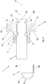
Figure 1 shows a sectional view with some separate parts of the device of the invention; -
Figure 2 shows a sectional view of the device of the invention; -
Figure 3 shows a plan view of one side of the device inFigure 2 ; -
Figure 4 shows a view of one side of a component of the device inFigure 2 ; -
Figure 5 shows a view of another side of the component inFigure 2 . - The same reference numerals in the figures identify the same elements or components.
- With reference to the figures, a control device 1 is shown for controlling the water level in a boiler (not shown since boilers are well known in the art). The control device 1 comprises
- a
fastening element 2 apt to fasten the control device 1 to a boiler wall, with a through hole defining an axis X, - an insulator 3 inserted into the hole of the
fastening element 2, - a sealing ring 4,
- a level probe 5 having a portion coated by the insulator 3 and one end 6 intended to be within the boiler when the control device 1 is fastened to the boiler wall,
- Preferably, the level probe 5 and the insulator 3 have a longitudinal axis coincident with axis X. The through hole is delimited by an inner wall 9, shaped so as to form the
circumferential abutment area 8, or shoulder, for the sealing ring, which is preferably an elastomeric o-ring 4. Therefore, theabutment area 8 is internal to thefastening element 2. In particular, the wall 9 of the fastening element comprises afirst area 10 with a first inner diameter, asecond area 11 with a second inner diameter smaller than the first inner diameter, and athird area 12 for the junction between thefirst area 10 and thesecond area 11. Thethird area 12 is tapered towards thesecond area 11 so as to define theabutment area 8. Moreover, the fasteningelement 2 comprises an externally threadedportion 13 apt to be screwed to a boiler wall, in particular to a threaded opening of the boiler wall. Preferably, theabutment area 8 is inside the threadedportion 13. Preferably, the extension along the axis X of the threadedportion 13 is approximately equal to the extension along the axis X of the thickness of the boiler wall where the opening is provided. Thefastening element 2 also comprises ahead 14, adjacent and coaxial to the threadedportion 13, which is a part apt to abut against the outer face of the boiler wall when the threadedportion 13 is screwed into the boiler wall opening. In particular, the extension in the direction perpendicular to the axis X ofhead 14 is greater than the outer diameter of the threadedportion 13. In order to favor the screwing of thefastening element 2,head 14 is shaped so as to be maneuvered with a common tightening tool. For example, in this embodiment,head 14 has a hexagonal profile. Preferably, in the face ofhead 14 directed towards the boiler wall when thefastening element 2 is screwed to the boiler, anannular groove 15 is provided where a gasket can be accommodated, e.g., another sealing ring or an o-ring (not shown). Thefastening element 2 is preferably made of stainless steel. Preferably, but not exclusively, thefastening element 2 is the only element by means of which the control device 1 is fastened to the boiler. - Insulator 3, being substantially cylindrical in shape, is mainly needed to provide an electrical insulation between the level probe 5 and the boiler, in particular between the level probe 5 and the
fastening element 2. To this end, insulator 3 is preferably made of plastic resistant to high temperatures, at least to 100°C. An example of suitable material for the construction of the insulator is polytetrafluoroethylene (PTFE). - Insulator 3 comprises a
first portion 16 with a first outer diameter, asecond portion 17 with a second outer diameter smaller than the first outer diameter, and a third junction portion between the first portion and the second portion, with a third outer diameter which is smaller than the second outer diameter. Thereby, the third portion forms thecircumferential groove 7 where the o-ring 4 is accommodated. When insulator 3 is inserted into thefastening element 2, it passes through the latter and the boiler wall, and has a portion internal to the boiler and a portion which remains external to the boiler. - Typically, the outer diameter of the
portion 17 of insulator 3 is smaller than the inner diameter of thearea 11 of thefastening element 2, and the outer diameter of theportion 16 of insulator 3 is smaller than the inner diameter of thearea 10 of thefastening element 2, and preferably greater than the inner diameter of thearea 11 of thefastening element 2. - The portion of insulator 3 which is external to the boiler has one
end 18, or an end area, which is outside thefastening element 2. A lockingelement 19 is preferably fastened to end 18 to provide a restraint, in addition to the wedging of the o-ring 4 in theabutment area 8, between the insulator 3 and thefastening element 2. The lockingelement 19 is apt to abut against thefastening element 2, so that, also considering the wedging of the o-ring 4, insulator 3 cannot move along axis X. in particular, the lockingelement 19 abuts against anabutment area 22 external to the boiler when thefastening element 2 is fastened to the boiler. In this embodiment, the lockingelement 19 abuts against anabutment area 22 of thefastening element 2 which is an outer surface, in particular against theface 22 ofhead 14 which is distal from the boiler. Furthermore, the locking element is elastic, preferably is an elastic clip, which gets stuck into tworecesses 20 obtained into theend 18 of insulator 3. Alternatively, a single circular recess is provided. The locking element can also be of another type, without the need to include the recesses. For example, a Starlock®-type washer can be used. Insulator 3 is preferably fastened to thefastening element 2 only by means of the wedging of the o-ring 4 and possibly also by means of the lockingelement 19. - The level probe 5 is fastened to insulator 3 and has a portion surrounded, or coated, by the latter. In particular, such a portion is immersed into the insulator and the longitudinal axis thereof is coincident to the axis X when the control device 1 is fastened to the boiler. Preferably, the insulator 3 and the level probe 5 are co-molded. The level probe 5 passes through insulator 3, and therefore through the
fastening element 2 and the boiler wall, and has one end 6, or end portion, internal to the boiler and oneend 21 external to the boiler. The end 6 is apt to detect the presence of water in the boiler, and is preferably bent into a hook as described below. Furthermore, it is preferable that the level probe 5 is at least partially flattened, i.e. it has a much smaller size than the other two. Theend 21 of the level probe 5 protrudes, along axis X, beyond theend 18 of insulator 3. Such anend 21 of the level probe 5 is preferably shaped to be connected to a connector, e.g. of the Faston type, so as to be connected to another device (not shown), e.g. an electronic control unit, a solenoid valve, a pump, and the like. Preferably, the level probe 5 has a profile similar to that of insulator 3, comprising three portions arranged at the respective three portions of insulator 3, as shown for example inFigure 1 , where the portion of the level probe 5 surrounded by insulator 3 is drawn with a dashed line. Typically, the level probe is made of a material which is suitable for conducting electricity. For example, a suitable material for manufacturing the level probe is stainless steel. - Preferably, as shown in
Figures 2 ,4 and 5 , the level probe 5 is a substantially flat metal element, with the end 6 preferably folded at approximately 180°. In particular, the end 6, or end portion, of the level probe 5 comprises a firststraight segment 6a having a rectilinear longitudinal axis, substantially coincident with axis X. The end 6 also comprises a secondstraight segment 6b having a rectilinear longitudinal axis, parallel to and distinct from the longitudinal axis of thefirst segment 6a. In other words, the firststraight segment 6a and the secondstraight segment 6b are substantially parallel to each other. - The first
straight segment 6a and the secondstraight segment 6b are connected by athird segment 6c which is curvilinear. - This configuration of the level probe is particularly advantageous since it increases the exchange, or contact, surface with the water and reduces the thickness of accumulated limestone. For example, if the exchange surface triples, the thickness of accumulated limestone will be three times lower, so that the level probe preserves its sensitivity for a longer time.
- In an alternative not shown, the level probe 5 is bent so that the first
straight segment 6a and the secondstraight segment 6b, joined by acurved segment 6c, are not parallel but inclined with respect to each other with an angle from 0 to 180°, extremes excluded. A further alternative provides for the level probe not being bent, but substantially flat, and therefore the segments indicated by thereference numerals - As shown in
Figure 1 , the assembly comprising insulator 3, level probe 5 and o-ring 4 is insertable into the through hole of thefastening element 2 in the direction of the arrow indicated by the reference sign A. - The invention also includes an electric dispenser of hot drinks, in particular an electric coffee machine, comprising a control device according to the invention.
- After providing an explanatory description of the control device 1, those skilled in the art can appreciate the advantages thereof. The device of the invention provides a perfect hermetic sealing, preventing the leakage of water, liquid or vapor, from the boiler. In particular, when the liquid in the boiler is heated, the resulting pressure increase within the boiler pushes the insulator outwards, whereby it gets stuck with more strength into the
fastening element 2, thus pushing on the o-ring 4 which cannot go beyond theabutment area 8. Therefore, as the inner pressure of the boiler increases also the seal increases. The fact that, in addition to the possible lockingelement 19, no further fastening elements are required to retain the insulator to thefastening element 2 is also advantageous. In particular, elements which can determine the plastic deformation of insulator 3, e.g. threaded elements, are not required. The device is capable of working perfectly, without deteriorating, even at high temperatures, above 100°C. The manufacturing of the device of the invention is also very simple and cost-effective.
wherein the insulator has a circumferential groove where the sealing ring is accommodated, and wherein the sealing ring abuts against said first abutment area.
wherein the insulator 3 has a
wherein the sealing ring 4 abuts against said
Claims (10)
- A control device (1) for controlling a water level in a boiler, comprising- a fastening element (2) apt to fasten the control device (1) to a boiler wall, with a through hole defining an axis (X),- an insulator (3) inserted into the hole of the fastening element (2),- a level probe (5) having a portion coated by the insulator (3) and one end (6) destined to be within the boiler when the control device (1) is fastened to the boiler wall,wherein there is provided a first abutment area (8) which is circumferential and internal to the fastening element (2),
characterized in that it comprises a sealing ring (4)
in that the insulator (3) has a circumferential groove (7) where the sealing ring (4) is accommodated, and
in that the sealing ring (4) abuts against said first abutment area (8). - A control device (1) according to claim 1, comprising a locking element (19) restrainable to one end (18) of the insulator (3) and apt to abut against a second abutment area (22) provided on the fastening element (2),
wherein said end (18) of the insulator (3) and said second abutment area (22) are external to the boiler when the control device (1) is fastened to the boiler. - A control device (1) according to claim 1 or 2, wherein the insulator (3) comprises a first portion (16) with a first outer diameter, a second portion (17) with a second outer diameter smaller than the first outer diameter, and a third portion of junction between the first portion (16) and the second portion (17), with a third outer diameter which is smaller than the second outer diameter,
whereby the third portion forms the circumferential groove (7) where the sealing ring (4) is accommodated. - A control device (1) according to any one of the preceding claims, wherein said through hole is delimited by an inner wall (9) of the fastening element (2), wherein the inner wall (9) is shaped so as to form said first abutment area (8),
and wherein the insulator (3) is inserted into said through hole. - A control device (1) according to claim 4, wherein said inner wall (9) comprises a first area (10) with a first inner diameter, a second area (11) with a second inner diameter smaller than the first inner diameter, so as to form said first abutment area (8).
- A control device (1) according to claim 5, wherein said wall (9) of the fastening element (2) comprises a third area (12) of junction between the first area (10) and the second area (11), wherein the third area (12) is tapered towards the second area (11) so as to define said first abutment area (8).
- A control device according to any one of the preceding claims, wherein the fastening element (2) comprises an externally threaded portion (13) apt to be screwed to a boiler wall.
- A control device (1) according to any one of the preceding claims, wherein the insulator (3) is made of plastic.
- A control device (1) according to any one of the preceding claims, wherein the end (6) comprises a first straight segment (6a), a second straight segment (6b) parallel to the first straight segment (6a), and a curved segment (6c) which connects the first straight segment (6a) and the second straight segment (6b).
- An electric dispenser of hot drinks, comprising a control device according to any one of the preceding claims.
Applications Claiming Priority (2)
| Application Number | Priority Date | Filing Date | Title |
|---|---|---|---|
| ITUB2016A000811A ITUB20160811A1 (en) | 2016-02-17 | 2016-02-17 | BOILER CONTROL DEVICE |
| PCT/IB2017/050842 WO2017141171A1 (en) | 2016-02-17 | 2017-02-15 | Control device for a boiler |
Publications (2)
| Publication Number | Publication Date |
|---|---|
| EP3416532A1 EP3416532A1 (en) | 2018-12-26 |
| EP3416532B1 true EP3416532B1 (en) | 2020-03-25 |
Family
ID=55969365
Family Applications (1)
| Application Number | Title | Priority Date | Filing Date |
|---|---|---|---|
| EP17716600.6A Active EP3416532B1 (en) | 2016-02-17 | 2017-02-15 | Control device for a boiler |
Country Status (3)
| Country | Link |
|---|---|
| EP (1) | EP3416532B1 (en) |
| IT (1) | ITUB20160811A1 (en) |
| WO (1) | WO2017141171A1 (en) |
Family Cites Families (3)
| Publication number | Priority date | Publication date | Assignee | Title |
|---|---|---|---|---|
| DE102004004571A1 (en) * | 2003-07-29 | 2005-08-25 | Pav Patentverwertung Kg | Hot drink preparation machine, especially a coffee maker has a temperature sensor that is mounted in a collet and detachably connected to this using a connection between the collet and a sensor mounting |
| CN202836671U (en) * | 2012-10-12 | 2013-03-27 | 王德元 | Adjustable dual sealed liquid level sensor |
| CN203011468U (en) * | 2012-12-19 | 2013-06-19 | 董过房 | Water-level detection device |
-
2016
- 2016-02-17 IT ITUB2016A000811A patent/ITUB20160811A1/en unknown
-
2017
- 2017-02-15 WO PCT/IB2017/050842 patent/WO2017141171A1/en not_active Ceased
- 2017-02-15 EP EP17716600.6A patent/EP3416532B1/en active Active
Non-Patent Citations (1)
| Title |
|---|
| None * |
Also Published As
| Publication number | Publication date |
|---|---|
| WO2017141171A1 (en) | 2017-08-24 |
| EP3416532A1 (en) | 2018-12-26 |
| ITUB20160811A1 (en) | 2017-08-17 |
Similar Documents
| Publication | Publication Date | Title |
|---|---|---|
| EP3844464B1 (en) | Temperature sensor system | |
| US9145665B2 (en) | Adjustable locking spout shank | |
| US8337081B1 (en) | Sensor assembly for mounting a temperature sensor to a tank | |
| JP2015068500A (en) | Synthetic resin pipe fittings | |
| US9593700B2 (en) | Self-locking plug | |
| JP2017535790A (en) | Magnetic flowmeter fluency assembly with spring loaded seal ring | |
| CN110234920B (en) | Method and apparatus for mounting a safety cap to a fluid connector using optical and inductive sensors | |
| WO2017141171A1 (en) | Control device for a boiler | |
| US6513377B1 (en) | Boiler level indicator | |
| US20110123261A1 (en) | Threaded connection piece | |
| RU2386075C2 (en) | Improved pipe connection | |
| US20140203553A1 (en) | Connector Assembly for Liquid Media Pipes | |
| KR101232319B1 (en) | Pipe connector | |
| EP1855092A1 (en) | Electrode holder | |
| KR101690517B1 (en) | A heater for manufacturing semiconductor | |
| KR20210046648A (en) | Euro joint structure | |
| GB2463896A (en) | Plug-in pipe coupling | |
| CN215261966U (en) | Water level detection device | |
| JP7488767B2 (en) | Piping system, piping information system, and pipe joint system | |
| KR101544312B1 (en) | Nonmetallic sheet heater and binding device for change simplicity of the same and steam generating device | |
| EP2667092B1 (en) | Radial nozzle assembly for a pressure vessel | |
| US20220220991A1 (en) | Screw connection system, method for screwing together reinforced long molded parts, and use of a screw connection system | |
| EP2954241B1 (en) | Tamperproof screwing coupling system for valve of a thermal/sanitary plant for buildings | |
| KR20180060563A (en) | A valve socket for increasing watertight | |
| KR100933794B1 (en) | Heating tube end device of heating medium heating system |
Legal Events
| Date | Code | Title | Description |
|---|---|---|---|
| STAA | Information on the status of an ep patent application or granted ep patent |
Free format text: STATUS: UNKNOWN |
|
| STAA | Information on the status of an ep patent application or granted ep patent |
Free format text: STATUS: THE INTERNATIONAL PUBLICATION HAS BEEN MADE |
|
| PUAI | Public reference made under article 153(3) epc to a published international application that has entered the european phase |
Free format text: ORIGINAL CODE: 0009012 |
|
| STAA | Information on the status of an ep patent application or granted ep patent |
Free format text: STATUS: REQUEST FOR EXAMINATION WAS MADE |
|
| 17P | Request for examination filed |
Effective date: 20180914 |
|
| AK | Designated contracting states |
Kind code of ref document: A1 Designated state(s): AL AT BE BG CH CY CZ DE DK EE ES FI FR GB GR HR HU IE IS IT LI LT LU LV MC MK MT NL NO PL PT RO RS SE SI SK SM TR |
|
| AX | Request for extension of the european patent |
Extension state: BA ME |
|
| DAV | Request for validation of the european patent (deleted) | ||
| DAX | Request for extension of the european patent (deleted) | ||
| RAP1 | Party data changed (applicant data changed or rights of an application transferred) |
Owner name: I.R.C.A. S.P.A. INDUSTRIA RESISTENZE CORAZZATE E A |
|
| GRAP | Despatch of communication of intention to grant a patent |
Free format text: ORIGINAL CODE: EPIDOSNIGR1 |
|
| STAA | Information on the status of an ep patent application or granted ep patent |
Free format text: STATUS: GRANT OF PATENT IS INTENDED |
|
| INTG | Intention to grant announced |
Effective date: 20191015 |
|
| GRAS | Grant fee paid |
Free format text: ORIGINAL CODE: EPIDOSNIGR3 |
|
| GRAA | (expected) grant |
Free format text: ORIGINAL CODE: 0009210 |
|
| STAA | Information on the status of an ep patent application or granted ep patent |
Free format text: STATUS: THE PATENT HAS BEEN GRANTED |
|
| AK | Designated contracting states |
Kind code of ref document: B1 Designated state(s): AL AT BE BG CH CY CZ DE DK EE ES FI FR GB GR HR HU IE IS IT LI LT LU LV MC MK MT NL NO PL PT RO RS SE SI SK SM TR |
|
| REG | Reference to a national code |
Ref country code: GB Ref legal event code: FG4D |
|
| REG | Reference to a national code |
Ref country code: AT Ref legal event code: REF Ref document number: 1247551 Country of ref document: AT Kind code of ref document: T Effective date: 20200415 Ref country code: IE Ref legal event code: FG4D |
|
| REG | Reference to a national code |
Ref country code: DE Ref legal event code: R096 Ref document number: 602017013641 Country of ref document: DE |
|
| PG25 | Lapsed in a contracting state [announced via postgrant information from national office to epo] |
Ref country code: NO Free format text: LAPSE BECAUSE OF FAILURE TO SUBMIT A TRANSLATION OF THE DESCRIPTION OR TO PAY THE FEE WITHIN THE PRESCRIBED TIME-LIMIT Effective date: 20200625 Ref country code: FI Free format text: LAPSE BECAUSE OF FAILURE TO SUBMIT A TRANSLATION OF THE DESCRIPTION OR TO PAY THE FEE WITHIN THE PRESCRIBED TIME-LIMIT Effective date: 20200325 Ref country code: RS Free format text: LAPSE BECAUSE OF FAILURE TO SUBMIT A TRANSLATION OF THE DESCRIPTION OR TO PAY THE FEE WITHIN THE PRESCRIBED TIME-LIMIT Effective date: 20200325 |
|
| PG25 | Lapsed in a contracting state [announced via postgrant information from national office to epo] |
Ref country code: LV Free format text: LAPSE BECAUSE OF FAILURE TO SUBMIT A TRANSLATION OF THE DESCRIPTION OR TO PAY THE FEE WITHIN THE PRESCRIBED TIME-LIMIT Effective date: 20200325 Ref country code: SE Free format text: LAPSE BECAUSE OF FAILURE TO SUBMIT A TRANSLATION OF THE DESCRIPTION OR TO PAY THE FEE WITHIN THE PRESCRIBED TIME-LIMIT Effective date: 20200325 Ref country code: HR Free format text: LAPSE BECAUSE OF FAILURE TO SUBMIT A TRANSLATION OF THE DESCRIPTION OR TO PAY THE FEE WITHIN THE PRESCRIBED TIME-LIMIT Effective date: 20200325 Ref country code: BG Free format text: LAPSE BECAUSE OF FAILURE TO SUBMIT A TRANSLATION OF THE DESCRIPTION OR TO PAY THE FEE WITHIN THE PRESCRIBED TIME-LIMIT Effective date: 20200625 Ref country code: GR Free format text: LAPSE BECAUSE OF FAILURE TO SUBMIT A TRANSLATION OF THE DESCRIPTION OR TO PAY THE FEE WITHIN THE PRESCRIBED TIME-LIMIT Effective date: 20200626 |
|
| REG | Reference to a national code |
Ref country code: NL Ref legal event code: MP Effective date: 20200325 |
|
| REG | Reference to a national code |
Ref country code: LT Ref legal event code: MG4D |
|
| PG25 | Lapsed in a contracting state [announced via postgrant information from national office to epo] |
Ref country code: NL Free format text: LAPSE BECAUSE OF FAILURE TO SUBMIT A TRANSLATION OF THE DESCRIPTION OR TO PAY THE FEE WITHIN THE PRESCRIBED TIME-LIMIT Effective date: 20200325 |
|
| PG25 | Lapsed in a contracting state [announced via postgrant information from national office to epo] |
Ref country code: RO Free format text: LAPSE BECAUSE OF FAILURE TO SUBMIT A TRANSLATION OF THE DESCRIPTION OR TO PAY THE FEE WITHIN THE PRESCRIBED TIME-LIMIT Effective date: 20200325 Ref country code: PT Free format text: LAPSE BECAUSE OF FAILURE TO SUBMIT A TRANSLATION OF THE DESCRIPTION OR TO PAY THE FEE WITHIN THE PRESCRIBED TIME-LIMIT Effective date: 20200818 Ref country code: IS Free format text: LAPSE BECAUSE OF FAILURE TO SUBMIT A TRANSLATION OF THE DESCRIPTION OR TO PAY THE FEE WITHIN THE PRESCRIBED TIME-LIMIT Effective date: 20200725 Ref country code: CZ Free format text: LAPSE BECAUSE OF FAILURE TO SUBMIT A TRANSLATION OF THE DESCRIPTION OR TO PAY THE FEE WITHIN THE PRESCRIBED TIME-LIMIT Effective date: 20200325 Ref country code: SK Free format text: LAPSE BECAUSE OF FAILURE TO SUBMIT A TRANSLATION OF THE DESCRIPTION OR TO PAY THE FEE WITHIN THE PRESCRIBED TIME-LIMIT Effective date: 20200325 Ref country code: LT Free format text: LAPSE BECAUSE OF FAILURE TO SUBMIT A TRANSLATION OF THE DESCRIPTION OR TO PAY THE FEE WITHIN THE PRESCRIBED TIME-LIMIT Effective date: 20200325 Ref country code: EE Free format text: LAPSE BECAUSE OF FAILURE TO SUBMIT A TRANSLATION OF THE DESCRIPTION OR TO PAY THE FEE WITHIN THE PRESCRIBED TIME-LIMIT Effective date: 20200325 Ref country code: SM Free format text: LAPSE BECAUSE OF FAILURE TO SUBMIT A TRANSLATION OF THE DESCRIPTION OR TO PAY THE FEE WITHIN THE PRESCRIBED TIME-LIMIT Effective date: 20200325 |
|
| REG | Reference to a national code |
Ref country code: AT Ref legal event code: MK05 Ref document number: 1247551 Country of ref document: AT Kind code of ref document: T Effective date: 20200325 |
|
| REG | Reference to a national code |
Ref country code: DE Ref legal event code: R097 Ref document number: 602017013641 Country of ref document: DE |
|
| PG25 | Lapsed in a contracting state [announced via postgrant information from national office to epo] |
Ref country code: AT Free format text: LAPSE BECAUSE OF FAILURE TO SUBMIT A TRANSLATION OF THE DESCRIPTION OR TO PAY THE FEE WITHIN THE PRESCRIBED TIME-LIMIT Effective date: 20200325 Ref country code: DK Free format text: LAPSE BECAUSE OF FAILURE TO SUBMIT A TRANSLATION OF THE DESCRIPTION OR TO PAY THE FEE WITHIN THE PRESCRIBED TIME-LIMIT Effective date: 20200325 Ref country code: ES Free format text: LAPSE BECAUSE OF FAILURE TO SUBMIT A TRANSLATION OF THE DESCRIPTION OR TO PAY THE FEE WITHIN THE PRESCRIBED TIME-LIMIT Effective date: 20200325 |
|
| PLBE | No opposition filed within time limit |
Free format text: ORIGINAL CODE: 0009261 |
|
| STAA | Information on the status of an ep patent application or granted ep patent |
Free format text: STATUS: NO OPPOSITION FILED WITHIN TIME LIMIT |
|
| PG25 | Lapsed in a contracting state [announced via postgrant information from national office to epo] |
Ref country code: PL Free format text: LAPSE BECAUSE OF FAILURE TO SUBMIT A TRANSLATION OF THE DESCRIPTION OR TO PAY THE FEE WITHIN THE PRESCRIBED TIME-LIMIT Effective date: 20200325 |
|
| 26N | No opposition filed |
Effective date: 20210112 |
|
| PG25 | Lapsed in a contracting state [announced via postgrant information from national office to epo] |
Ref country code: SI Free format text: LAPSE BECAUSE OF FAILURE TO SUBMIT A TRANSLATION OF THE DESCRIPTION OR TO PAY THE FEE WITHIN THE PRESCRIBED TIME-LIMIT Effective date: 20200325 |
|
| PG25 | Lapsed in a contracting state [announced via postgrant information from national office to epo] |
Ref country code: MC Free format text: LAPSE BECAUSE OF FAILURE TO SUBMIT A TRANSLATION OF THE DESCRIPTION OR TO PAY THE FEE WITHIN THE PRESCRIBED TIME-LIMIT Effective date: 20200325 |
|
| GBPC | Gb: european patent ceased through non-payment of renewal fee |
Effective date: 20210215 |
|
| REG | Reference to a national code |
Ref country code: BE Ref legal event code: MM Effective date: 20210228 |
|
| PG25 | Lapsed in a contracting state [announced via postgrant information from national office to epo] |
Ref country code: LU Free format text: LAPSE BECAUSE OF NON-PAYMENT OF DUE FEES Effective date: 20210215 Ref country code: LI Free format text: LAPSE BECAUSE OF NON-PAYMENT OF DUE FEES Effective date: 20210228 Ref country code: CH Free format text: LAPSE BECAUSE OF NON-PAYMENT OF DUE FEES Effective date: 20210228 |
|
| PG25 | Lapsed in a contracting state [announced via postgrant information from national office to epo] |
Ref country code: IE Free format text: LAPSE BECAUSE OF NON-PAYMENT OF DUE FEES Effective date: 20210215 Ref country code: GB Free format text: LAPSE BECAUSE OF NON-PAYMENT OF DUE FEES Effective date: 20210215 Ref country code: FR Free format text: LAPSE BECAUSE OF NON-PAYMENT OF DUE FEES Effective date: 20210228 |
|
| PG25 | Lapsed in a contracting state [announced via postgrant information from national office to epo] |
Ref country code: BE Free format text: LAPSE BECAUSE OF NON-PAYMENT OF DUE FEES Effective date: 20210228 |
|
| PG25 | Lapsed in a contracting state [announced via postgrant information from national office to epo] |
Ref country code: CY Free format text: LAPSE BECAUSE OF FAILURE TO SUBMIT A TRANSLATION OF THE DESCRIPTION OR TO PAY THE FEE WITHIN THE PRESCRIBED TIME-LIMIT Effective date: 20200325 |
|
| P01 | Opt-out of the competence of the unified patent court (upc) registered |
Effective date: 20230525 |
|
| PG25 | Lapsed in a contracting state [announced via postgrant information from national office to epo] |
Ref country code: HU Free format text: LAPSE BECAUSE OF FAILURE TO SUBMIT A TRANSLATION OF THE DESCRIPTION OR TO PAY THE FEE WITHIN THE PRESCRIBED TIME-LIMIT; INVALID AB INITIO Effective date: 20170215 |
|
| PG25 | Lapsed in a contracting state [announced via postgrant information from national office to epo] |
Ref country code: MK Free format text: LAPSE BECAUSE OF FAILURE TO SUBMIT A TRANSLATION OF THE DESCRIPTION OR TO PAY THE FEE WITHIN THE PRESCRIBED TIME-LIMIT Effective date: 20200325 |
|
| PG25 | Lapsed in a contracting state [announced via postgrant information from national office to epo] |
Ref country code: TR Free format text: LAPSE BECAUSE OF FAILURE TO SUBMIT A TRANSLATION OF THE DESCRIPTION OR TO PAY THE FEE WITHIN THE PRESCRIBED TIME-LIMIT Effective date: 20200325 |
|
| PG25 | Lapsed in a contracting state [announced via postgrant information from national office to epo] |
Ref country code: MT Free format text: LAPSE BECAUSE OF FAILURE TO SUBMIT A TRANSLATION OF THE DESCRIPTION OR TO PAY THE FEE WITHIN THE PRESCRIBED TIME-LIMIT Effective date: 20200325 |
|
| PGFP | Annual fee paid to national office [announced via postgrant information from national office to epo] |
Ref country code: DE Payment date: 20260324 Year of fee payment: 10 |
|
| PGFP | Annual fee paid to national office [announced via postgrant information from national office to epo] |
Ref country code: IT Payment date: 20260225 Year of fee payment: 10 |