EP3416455A1 - Wireless communications system and base station - Google Patents
Wireless communications system and base station Download PDFInfo
- Publication number
- EP3416455A1 EP3416455A1 EP17763306.2A EP17763306A EP3416455A1 EP 3416455 A1 EP3416455 A1 EP 3416455A1 EP 17763306 A EP17763306 A EP 17763306A EP 3416455 A1 EP3416455 A1 EP 3416455A1
- Authority
- EP
- European Patent Office
- Prior art keywords
- base station
- signal
- rau
- processing
- user equipment
- Prior art date
- Legal status (The legal status is an assumption and is not a legal conclusion. Google has not performed a legal analysis and makes no representation as to the accuracy of the status listed.)
- Granted
Links
Images





Classifications
-
- H—ELECTRICITY
- H04—ELECTRIC COMMUNICATION TECHNIQUE
- H04B—TRANSMISSION
- H04B7/00—Radio transmission systems, i.e. using radiation field
- H04B7/02—Diversity systems; Multi-antenna system, i.e. transmission or reception using multiple antennas
- H04B7/022—Site diversity; Macro-diversity
- H04B7/024—Co-operative use of antennas of several sites, e.g. in co-ordinated multipoint or co-operative multiple-input multiple-output [MIMO] systems
-
- H—ELECTRICITY
- H04—ELECTRIC COMMUNICATION TECHNIQUE
- H04W—WIRELESS COMMUNICATION NETWORKS
- H04W72/00—Local resource management
- H04W72/50—Allocation or scheduling criteria for wireless resources
- H04W72/54—Allocation or scheduling criteria for wireless resources based on quality criteria
- H04W72/542—Allocation or scheduling criteria for wireless resources based on quality criteria using measured or perceived quality
-
- H—ELECTRICITY
- H04—ELECTRIC COMMUNICATION TECHNIQUE
- H04B—TRANSMISSION
- H04B7/00—Radio transmission systems, i.e. using radiation field
- H04B7/02—Diversity systems; Multi-antenna system, i.e. transmission or reception using multiple antennas
- H04B7/04—Diversity systems; Multi-antenna system, i.e. transmission or reception using multiple antennas using two or more spaced independent antennas
- H04B7/0413—MIMO systems
-
- H—ELECTRICITY
- H04—ELECTRIC COMMUNICATION TECHNIQUE
- H04W—WIRELESS COMMUNICATION NETWORKS
- H04W88/00—Devices specially adapted for wireless communication networks, e.g. terminals, base stations or access point devices
- H04W88/08—Access point devices
-
- H—ELECTRICITY
- H04—ELECTRIC COMMUNICATION TECHNIQUE
- H04W—WIRELESS COMMUNICATION NETWORKS
- H04W88/00—Devices specially adapted for wireless communication networks, e.g. terminals, base stations or access point devices
- H04W88/08—Access point devices
- H04W88/085—Access point devices with remote components
-
- H—ELECTRICITY
- H04—ELECTRIC COMMUNICATION TECHNIQUE
- H04W—WIRELESS COMMUNICATION NETWORKS
- H04W92/00—Interfaces specially adapted for wireless communication networks
- H04W92/04—Interfaces between hierarchically different network devices
Definitions
- An aspect of the present disclosure relates to a radio communication system and a base station.
- LTE Long Term Evolution
- LTE-A LTE-Advanced
- C-RAN centralized radio access network
- the C-RAN is formed of one or a plurality of remote antenna units (RAUs) which are remote installation type base stations (slave station), and a baseband unit (BBU) that is a base station (master station) that concentrically controls the RAU.
- RAUs remote antenna units
- BBU baseband unit
- the BBU has a function of Layer 1 to Layer 3 which are provided to the base station.
- a digital baseband signal, which is generated in the BBU, is transmitted to the RAU, and is transmitted from a radio frequency (RF) function unit provided to the RAU.
- RF radio frequency
- a network line that connects the BBU and the RAU is called a front haul (FH), and a common public radio interface (CPRI) is used as the FH in the LTE.
- FH front haul
- CPRI common public radio interface
- Non-Patent Document 1 " Docomo 5G white paper", September, 2014, NTT Docomo, Internet URL: https: //www.nttdocomo.co.jp/corporate/technology/whitepaper_5g/
- a band, which is necessary for the FH in the case of using 2 ⁇ 2 multiple input multiple output (MIMO), is approximately 16 times greater than a peak rate that is supported in the BBU.
- a band necessary for the CPRI is approximately 2.5 Gbps.
- the band necessary for the CPRI increments in proportion to an increase in the number of antennas and the system band.
- the band necessary for the FH significantly increases in accordance with an improvement in a peak rate.
- the band necessary for the CPRI is several hundreds of Gbps or greater, and thus it is difficult to cope with a current CPRI standard (maximum: 24.33 Gbps).
- an examination has been conducted to reduce a transmission amount through the FH by realizing a part of the layers mounted in the BBU on an RAU side.
- Various variations have been studied with respect to function sharing between the BBU and RAU.
- a plan in which the entirety of a plurality of kinds of processing of Layer 1 are implemented in RAU, and processing of Layer 2 or higher is implemented in the BBU a plan in which a part of the processing of Layer 1 is implemented on the RAU side, the remaining processing of Layer 1 and the processing of Layer 2 or higher are implemented on the BBU side, and the like have been studied.
- a network such as a passive optical network (PON) in which one optical fiber is shared by multiple nodes and Ethernet (registered trademark) to the FH has been studied ( Fig. 2 ) to implement the FH that is cheaper than the CPRI.
- the networks are shared by the multiple nodes, and thus it is considered that a control of a transmission amount through the FH is necessary in correspondence with a variation of a signal quantity between the nodes.
- processing capability of the RAU is relatively lower than that of the BBU. Accordingly, when simply reducing the transmission amount of the FH, a processing load of the RAU tends to increase. Accordingly, there is a need for a structure capable of appropriately changing the function sharing between the BBU and the RAU in correspondence with a situation in consideration of the processing load of the RAU, communication quality with a user equipment, and the like.
- a disclosed technology has been made in consideration of the above-described situations, and an object thereof is to provide a technology capable of appropriately changing function sharing between a BBU and an RAU in a radio communication network according to a C-RAN.
- a radio communication system including a first base station, a second base station, a third base station that performs a communication with the first base station and the second base station, and a user equipment that performs a communication with the first base station and the second base station.
- the radio communication system includes a determination unit that determines allocation of signal processing that is commonly performed by the first base station and the second base station and signal processing that is performed by the third base station, based on a predetermined reference value; a first signal processor that performs the signal processing allocated to the first base station in accordance with the allocation that is determined by the determination unit; a second signal processor that performs the signal processing allocated to the second base station in accordance with the allocation that is determined by the determination unit; and a third signal processor that performs the signal processing allocated to the third base station in accordance with the allocation that is determined by the determination unit.
- a technology is provided that is capable of appropriately changing function sharing between a BBU and an RAU in a radio communication network according to a C-RAN.
- LTE Long Term Evolution
- 5G Long Term Evolution
- LTE Long Term Evolution
- Fig. 3 is a view illustrating a system configuration example of the radio communication system according to the embodiment.
- the radio communication system according to this embodiment includes a BBU 1, an RAU 2a, an RAU 2b, and a user equipment UE.
- the RAU 2a and the RAU 2b will be described as "RAU 2".
- the RAU 2a and the RAU 2b are illustrated, but three or greater of RAUs 2 may be included.
- the BBU 1 may be referred to as an aggregate base station, a master station, or a base station (enhanced Node B (eNB)) in a simple manner.
- the RAU 2 may be referred to as a satellite base station, a slave station, or a base station in a simple manner.
- the BBU 1 and the RAU 2 transmits and receives a predetermined signal through an FH.
- the BBU 1 performs a control so that the RAU 2a and the RAU 2b transmits (cooperatively transmits) a DL signal to a user equipment UE in cooperation with each other.
- the BBU 1 performs a control so that composition, selection, and the like of a UL signal, which is received from each of the RAU 2a and the RAU 2b, are performed to receive (cooperatively receive) the UL signal from the user equipment UE on the BBU 1 side in a cooperative manner.
- Figs. 4A and 4B are views illustrating a function sharing example between a BBU and an RAU.
- Fig. 4A illustrates a function sharing example in a UL
- Fig. 4B illustrates a function sharing example in a DL.
- Boundaries "U1" to "U9" in Fig. 4A represent boundaries of a plurality of kinds of processing of UL which are respectively performed in the BBU 1 and the RAU 2. For example, in the case of function sharing in the boundary "U6", processing according to a function of Layer 2 or higher is performed on a BBU 1 side, and processing according to a function of Layer 1 is performed on an RAU 2 side.
- processing up to an FFT is performed on the RAU 2 side, and processing subsequent to resource demapping (resource element demapping) is performed on the BBU 1 side.
- the boundary "U1" corresponds to a configuration of connecting the BBU 1 and the RAU 2 by using a CPRI. Furthermore, in a case where a communication by an MIMO is not performed in the UL, signal detection processing is omitted.
- boundaries "D1" to “D10” in Fig. 4B represent boundaries of a plurality of kinds of processing of the DL which are respectively performed in the BBU 1 and the RAU 2.
- processing according to the function of Layer 2 or higher is performed on the BBU 1 side
- processing according to the function of Layer 1 is performed on the RAU 2 side.
- function sharing at the boundary "D2” among the plurality of kinds of processing according to the function of Layer 1, processing up to resource element mapping is performed on the BBU 1 side, and OFDM signal generation is performed on the RAU 2 side.
- the boundary "D1" corresponds to a configuration of connecting the BBU 1 and the RAU 2 by using the CPRI. Furthermore, in a case where a communication by the MIMO is not performed in the DL, processing layer mapper and processing of precoding are not performed.
- the BBU 1, the RAU 2a, and the RAU 2b according to this embodiment are capable of arbitrarily changing that the function sharing is to be made (signal processing is to be shared) at which boundary among boundaries "U1" to "U9” in an UL.
- the BBU 1, the RAU 2a, and the RAU 2b according to this embodiment are capable of arbitrarily changing that the function sharing is to be made (signal processing is to be shared) at which boundary among boundaries "D1" to "D10" in a DL.
- the BBU 1, the RAU 2a, and the RAU 2b may be configured to commonly change the function sharing in a unit of the RAU 2a and the RAU 2b (in other words, the same function sharing may be allowed to be made in the RAU 2a and the RAU 2b), or to commonly change the function sharing in a unit of the user equipment UE (in other words, the same function sharing may be allowed to be made with respect to the same user equipment UE).
- the function sharing may be changed independently in the UL and the DL.
- Fig. 5 is a sequence diagram illustrating an example of a procedure for switching function sharing in the UL.
- step S101 the BBU 1 or the RAU 2 determine sharing (determine function sharing) between signal processing performed by the BBU 1 and signal processing performed by the RAU 2 (signal processing that is commonly performed by the RAU 2a and the RAU 2b).
- the boundaries ("U1" to "U9" of the function sharing between the BBU 1 and the RAU 2 may be determined in the BBU 1 or the RAU 2.
- the BBU 1 or the RAU 2 determines allocation of signal processing performed by the RAU 2 and signal processing performed by the BBU 1 on the basis of a predetermined reference value. For example, a table, in which a range of a predetermined reference value and the boundaries "U1" to "U9" in the UL are correlated one-to-one, is retained in the BBU 1 or the RAU 2.
- the BBU 1 or the RAU 2 may determine allocation of the signal processing performed by the RAU 2 and the signal processing performed by the BBU 1 by comparing the table and the predetermined reference value with each other.
- a predetermined threshold value may be retained in the BBU 1 or the RAU 2, and the BBU 1 or the RAU 2 may determine that the function sharing is to be made at which boundary among the boundaries "U1" to "U9” through determination of whether or not the predetermined reference value is equal to or greater than the predetermined threshold value.
- Acquisition (measurement) of the predetermined reference value may be performed by the BBU 1 or the RAU 2.
- the BBU 1 or the RAU 2 may notify a counterpart (the RAU 2 or the BBU 1) of an acquisition result (or measurement result) as necessary.
- a specific example of the predetermined reference value will be described later.
- the BBU 1 or the RAU 2 notifies a counterpart (the RAU 2 or the BBU 1) of the determination result of the function sharing. Furthermore, in a case where the RAU 2 makes a determination of the function sharing, the notification of the determination result of the function sharing is made between the RAU 2a and the RAU 2b. In addition, in a case where the RAU 2 makes a determination of the function sharing, the RAU 2a and the RAU 2b may apply an identifier, which indicates that signal processing according to which function has been performed on the RAU 2a side or on the RAU 2b side, to header information of a UL signal that is transmitted in a procedure in step S113a and step S113b to be described later. According to this, the function sharing of the UL can be changed in a dynamic manner.
- step S111a the RAU 2a receives an UL signal that is transmitted from the user equipment UE.
- step S11b the RAU 2b receives an UL signal that is transmitted from the user equipment UE.
- the RAU 2a performs signal processing to be performed by the RAU 2a (S112a), and transmits a signal after being subjected to the signal processing to the BBU 1 (S113a).
- the RAU 2b performs signal processing to be performed by the RAU 2b (S112b), and transmits a signal after being subjected to the signal processing to the BBU 1 (S113b).
- step S114 the BBU 1 performs signal processing to be performed by the BBU 1 (S114).
- the BBU 1 performs cooperative reception by using the UL signal transmitted from the RAU 2a and the UL signal transmitted from the RAU 2b.
- a method of performing the cooperative reception may be any method.
- the BBU 1 may select a UL signal from any one side among UL signals received from the RAU 2a and UL signals received from the RAU 2b, or may combine and receive the UL signals from the both sides.
- the BBU 1 may measure reception quality (SNR, SINR, and the like) of the UL signals from the RAU 2a and the RAU 2b to select a UL signal in which reception quality of the UL signal is satisfactory.
- reception quality SNR, SINR, and the like
- step S101 to S114 described above may be repetitively performed with a predetermined interval.
- the function sharing of the UL can be switched in a dynamic manner on the basis of a variation in reception quality of the UL signal or a DL signal, a variation in a processing load of the RAU 2, and the like.
- Fig. 6 is a sequence diagram illustrating an example of a procedure for switching function sharing in the DL. Furthermore, in this embodiment, the boundaries "D1" to "D10" of function sharing between the BBU 1 and the RAU 2 may be determined in the BBU 1 or the RAU 2.
- step S201 the BBU 1 or the RAU 2 determines sharing (determines function sharing) between signal processing performed by the BBU 1 and signal processing performed by the RAU 2 (signal processing that is commonly performed by the RAU 2a and RAU 2b).
- the boundaries ("D1" to "D10" of the function sharing between the BBU 1 and the RAU 2 may be determined in the BBU 1 or the RAU 2.
- the BBU 1 or the RAU 2 determines allocation of signal processing performed by the RAU 2 and signal processing performed by the BBU 1 on the basis of a predetermined reference value. For example, a table, in which a range of a predetermined reference value and the boundaries "D1" to "D10" in the DL are correlated one-to-one, is retained in the BBU 1 or the RAU 2.
- the BBU 1 or the RAU 2 may determine allocation of the signal processing performed by the RAU 2 and the signal processing performed by the BBU 1 by comparing the table and the predetermined reference value with each other.
- a predetermined threshold value may be retained in the BBU 1 or the RAU 2, and the BBU 1 or the RAU 2 may determine that the function sharing is to be made at which boundary among the boundaries "D1" to "D10" through determination of whether or not the predetermined reference value is equal to or greater than the predetermined threshold value.
- Acquisition (measurement) of the predetermined reference value may be performed by the BBU 1 or the RAU 2.
- the BBU 1 or the RAU 2 may notify a counterpart (the RAU 2 or the BBU 1) of an acquisition result (or measurement result) as necessary.
- the BBU 1 or the RAU 2 notifies a counterpart (the RAU 2 or the BBU 1) of the determination result of the function sharing. Furthermore, in a case where the RAU 2 determines the function sharing, the determination may be made by both of the RAU 2a and the RAU 2b or the determination may be made by any one of the RAU 2a and the RAU 2b, and a counterpart (the RAU 2b or the RAU 2a) may be notified of the determination result. In addition, in a case where the BBU 1 determines the function sharing, the BBU 1 may apply an identifier, which indicates that signal processing according to which function has been performed on the BBU 1 side, to header information of a DL signal that is transmitted in a procedure of step S211 to be described later. According to this, the function sharing of the DL can be switched in a dynamic manner.
- the BBU 1 performs signal processing to be performed by the BBU 1 with respect to a DL signal to be transmitted to the user equipment UE (S211), and transmits the DL signal after being subjected to the signal processing to the RAU 2a and the RAU 2b (S212a, S212b).
- the BBU 1 performs a control so that the RAU 2a and the RAU 2b transmit (cooperatively transmit) the DL signal to the user equipment UE in cooperation with each other in a procedure of step S211.
- the BBU 1 may be allowed to transmit a signal that is generated to both of the RAU 2a and the RAU 2b, or may be allowed to transmit the DL signal to any one of the RAU 2a and the RAU 2b.
- reception quality of the DL signal between the user equipment UE and the RAU 2a and reception quality of the DL signal between the user equipment UE and the RAU 2b may be allowed to be fed back from the user equipment UE to the BBU 1, and the BBU 1 may allowed to select the RAU 2 in which the reception quality is satisfactory.
- the BBU 1 may allow the user equipment UE to feed back a DL signal propagation state (for example, channel information and the like) between the user equipment UE and the RAU 2a and the RAU 2b to the BBU 1, and the BBU 1 may be allowed to generate a DL signal to be transmitted to the RAU 2a and a DL signal to be transmitted to the RAU 2b on the basis of the propagation state that is fed back and may be allowed to transmit the DL signals which are generated to the RAU 2a and the RAU 2b, respectively.
- a DL signal propagation state for example, channel information and the like
- the RAU 2a and the RAU 2b respectively perform signal processing to be performed by the RAU 2a or the RAU 2b on the basis of function sharing (S213a, S213b), and respectively transmit DL signals after being subjected to the signal processing to the user equipment UE (S214a, S214b).
- step S201 to S214 described above may be repetitively performed with a predetermined interval.
- the function sharing of the DL can be changed in a dynamic manner on the basis of a variation in reception quality of the UL signal or the DL signal, a variation in a processing load of the RAU 2, and the like.
- the predetermined reference value may be a value of a signal to interference plus noise power ratio (SINR) or a signal to noise ratio (SNR) of the UL signal received from the user equipment UE or the DL signal that is received by a user equipment UE.
- SINR signal to interference plus noise power ratio
- SNR signal to noise ratio
- a table in which a range of the SINR or the SNR and the boundaries in the UL or the DL are correlated with each other for example, a table, in which correlation of (boundaries “U9”, “U8”, “U7”, “U6”, “U5", “U4", “U3”, “U2”, and “U1") or (boundaries “D10”, “D9”, “D8”, “D7”, “D6”, “D5", “D4", “D3”, “D2”, and “D1") is made in the order from a side in which the range of the SINR or the SNR is great, may be used. That is, as the SINR or the SNR becomes greater, the number of processing performed on the RAU 2 side may be set to increase.
- the function sharing may be divided at a predetermined boundary in the UL or the DL (for example, the function sharing may be divided at "U6", "D7", and the like), and in a case where the SINR or the SNR is less than the predetermined threshold value, the function sharing may be divided at a predetermined boundary (for example, "U2", "D2", and the like) in the UL or the DL.
- Acquisition (measurement) of the SINR or the SNR may be performed in the RAU 2 or the BBU 1.
- a side in which an SINR or an SNR which is measured in the RAU 2a and an SINR or an SNR which is measured in the RAU 2b is greater, may be selected and used.
- the RAU 2 or the BBU 1 may acquire (measure) the SINR or the SNR for each user equipment UE on the basis of series of a reference signal or a resource position allocated to the user equipment UE.
- the RAU 2 may be notified of the series of the reference signal or the resource position allocated to the user equipment UE from the BBU 1 in advance.
- the changing of the function sharing per unit of the RAU 2 may be implemented by dividing scheduling time of a radio resource of the DL or UL for each user equipment UE.
- the predetermined reference value may be a cyclic redundancy check (CRC) check success rate of the UL signal that is received from the user equipment UE or the DL signal that is received by the user equipment UE.
- CRC check success rate represents a probability of determination as being correct in the CRC that is included in a radio signal transmitted with a predetermined physical channel. In a case where radio quality between the user equipment UE and the RAU 2 deteriorates, the CRC check success rate decreases.
- a table in which a range of the CRC check success rate and the boundaries in the UL or the DL are correlated with each other for example, a table, in which correlation of (boundaries “U9”, “U8”, “U7”, “U6”, “U5", “U4", “U3”, “U2”, and “U1") or (boundaries “D10”, “D9”, “D8”, “D7”, “D6”, “D5", “D4", “D3”, “D2”, and “D1") is made in the order from a side in which a range of the CRC check success rate is high, may be used. That is, as the CRC check success rate is high, the number of processing performed on the RAU 2 side may be set to increase.
- the function sharing may be divided at a predetermined boundary in the UL or the DL (for example, the function sharing may be divided at "U6", "D7", and the like), and in a case where the CRC check success rate is less than the predetermine threshold value, the function sharing may be divided at a predetermined boundary (for example, "U2", "D2", and the like) in the UL or the DL.
- Acquisition (measurement) of the CRC check success rate may be performed by the RAU 2 or the BBU 1.
- a side in which a CRC check success rate measured by the RAU 2a and a CRC check success rate measured by the RAU 2b is greater, may be selected and used.
- the CRC check is performed when performing decoding processing, and thus it is preferable that a device (BBU 1 or RAU 2), which performs processing according to the decoding, performs acquisition of the CRC check success rate.
- the predetermined reference value may be the number of retransmission times of the UL signal or the DL signal from the user equipment UE in a predetermined period (or an average value of the number of retransmission times in the predetermined period).
- the number of retransmission times of the DL signal to the user equipment UE in a predetermined period may be counted as the number of notification times of NAK by a PUCCH or a PUSCH.
- a table in which a range of the number of retransmission times and the boundaries in the UL or the DL are correlated with each other for example, a table, in which correlation of (boundaries “U9”, “U8”, “U7” “U6” “U5", “U4", “U3”, “U2”, and “U1") or (boundaries “D10”, “D9”, “D8”, “D7”, “D6", “D5", “D4", “D3”, “D2”, and “D1") is made in the order from a side in which a range of the number of retransmission times is small, may be used. That is, as the number of retransmission times is small, processing performed on the RAU 2 side may be set to increase.
- the function sharing may be divided at a predetermined boundary (for example, "U6", “D7”, and the like) in the UL or the DL, and in a case where the number of retransmission times is equal to or greater than the predetermined threshold value, the function sharing may be divided at a predetermined boundary (for example, "U2", "D2", and the like) in the UL or the DL.
- Acquisition (measurement) of the number of retransmission times may be performed in the RAU 2 or the BBU 1.
- the measurement is performed by the RAU 2, an average value of the number of measurement times in the RAU 2a and the number of measurement times in the RAU 2b may be used, and a side, in which the number of measurement times is greater, may be selected and used.
- reception of the NAK is performed with a signal after being decoded, and thus it is preferable that the acquisition of the number of retransmission times is performed by a device (the BBU 1, the RAU 2a, or the RAU 2b) that performs processing in accordance with decoding.
- the predetermined reference value may be a channel estimation error of the UL signal that is received from the user equipment UE or the DL signal that is received by the user equipment UE.
- the channel estimation error represents an index indicating that a variation (dispersion) occurs to a certain extent between an average value of results obtained by performing channel estimation by using a plurality of reference signals included in the UL signal that is received from the user equipment UE or the DL signal which the user equipment UE receives, and a result obtained by performing channel estimation of each of the reference signals. In a case where radio quality between the user equipment UE and the RAU 2 deteriorates, the channel estimation error increases.
- a table in which a range of the channel estimation error and the boundaries in the UL or the DL are correlated with each other for example, a table, in which correlation of (boundaries “U9”, “U8”, “U7”, “U6”, “U5", “U4", “U3”, “U2”, and “U1") or (boundaries “D10”, “D9”, “D8”, “D7”, “D6”, “D5", “D4", “D3”, “D2”, and “D1") is made in the order from a side in which a range of the channel estimation error is small, may be used. That is, as the range of the channel estimation error is small, processing performed on the RAU 2 side may be set to increase.
- the function sharing may be divided at a predetermined boundary (for example, "U6", “D7”, and the like) in the UL or the DL, and in a case where the channel estimation error is equal to or greater than the predetermined threshold value, the function sharing may be divided at a predetermined boundary (for example, "U2", “D2", and the like) in the UL or the DL.
- the predetermined reference value may be the magnitude of a processing load of the RAU 2 (a processor utilization rate, a memory utilization rate, the amount of data between the BBU 1 and the RAU 2, and the like).
- a processing load of the RAU 2 which is the greatest between a processing load of the RAU 2a and a processing load of the RAU 2b, may be used.
- the function sharing may be divided at a predetermined boundary (for example, "U6", “D7”, and the like) in the UL or the DL, and in a case where the magnitude of the processing load is equal to or greater than the predetermined threshold value, the function sharing may be divided at a predetermined boundary (for example, "U2", "D2", and the like) in the UL or the DL.
- the processing load of the RAU 2 may be measured by the RAU 2a and/or the RAU 2b, or may be estimated by the BBU 1 on the basis of the amount of data transmitted to the RAU 2a and/or the RAU 2b from the BBU 1, the amount of data that is scheduled by the BBU 1 with respect to the RAU 2a and/or the RAU 2b, and the like.
- the predetermined reference value may relate to whether or not at least one of the number of antennas provided to the RAU 2a and the number of antennas provided to the RAU 2b is equal to or greater than the number of antennas provided to the user equipment UE.
- the predetermined boundary for example, "U6" and the like in the UL.
- the function sharing may be made at a predetermined boundary (for example, "U2" and the like).
- the number of the antennas included in the user equipment UE may be reported from the user equipment UE to the BBU1 by a higher layer, etc.
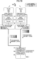
- Figs. 7A and 7B are views illustrating an operation example of function sharing changing processing in the UL.
- Figs. 7A and 7B illustrate an operation example in the case of using the SINR as the predetermined reference value.
- a part of various kinds of signal processing of Layer 1 as illustrated in Fig. 4A is not illustrated, and boundaries "U2", “U4", and “U6” illustrated in Figs. 7A and 7B respectively correspond to the boundaries "U2", “U4", and "U6” illustrated in Fig. 4(a) .
- the boundaries illustrated in Figs. 7A and 7B are examples, and it is not intended to limit the boundaries. For example, the boundary "U2" in Figs.
- FIG. 7A and 7B may be the boundary "U3", and the boundary "U4" in Figs. 7A and 7B may be the boundary "U5".
- the function sharing may be changed at any one of boundaries "U1", and "U7” to "U9".
- the BBU 1 determines that the entirety of a plurality of kinds of signal processing in accordance with Layer 1 are performed on the RAU 2a side and on RAU 2b side (determines that function sharing is made at the region "U6"). Subsequently, the BBU 1 notifies the RAU 2a and the RAU 2b of the determination result.
- the RAU 2a and the RAU 2b perform the entirety of the plurality of kinds of signal processing in accordance with Layer 1 on the basis of the determination result that is transmitted in the notification, and transmit a UL signal that is decoded to the BBU 1 through the FH.
- the BBU 1 selects any one UL signal among UL signals which are received from the RAU 2a and the RAU 2b and are decoded, and performs signal processing subsequent to Layer 2 with respect to the UL signal that is selected.
- the BBU 1 determines that among the plurality of kinds of signal processing according to Layer 1, processing up to FFT processing is performed on the RAU 2a side and the RAU 2b side, and the subsequent signal processing is performed on the BBU 1 side (determines that function sharing is made at the region "U2"). Then, the BBU 1 notifies the RAU 2a and the RAU 2b of the determination result.
- the RAU 2a and the RAU 2b perform signal processing up to the FFT processing among the plurality of kinds of signal processing according to Layer 1 on the basis of the determination result that is transmitted in the notification, and transmits the UL signal after the FFT processing to the BBU 1 through the FH.
- the BBU 1 performs cooperative reception (for example, minimum mean squared error (MMSE) composition, composition by maximum likelihood detection (MLD), and the like) with respect to the UL signals which are received from the RAU 2a and the RAU 2b and are subjected to the FFT processing, and performs signal processing subsequent to Layer 2.
- MMSE minimum mean squared error
- MLD maximum likelihood detection
- the BBU 1 may notify the RAU 2a and the RAU 2b of a determination result for each user equipment UE and information (for example, a radio resource position in a frequency direction, and the like) for identification of the user equipment UE in correlation with each other so that the RAU 2a and the RAU 2b can recognize that which radio resource is scheduled to which a user equipment UE on the RAU 2a side and the RAU 2b side.
- information for example, a radio resource position in a frequency direction, and the like
- the entirety of the plurality of kinds of signal processing of Layer 1 are performed on the RAU 2 side, and thus it is possible to secure reception performance of the UL signal while reducing the transmission amount through the FH. Furthermore, since the transmission amount through the FH is reduced, it is possible to suppress occurrence of transmission delay.
- the cooperative reception is performed on the BBU 1 side, and thus it is possible to secure reception performance of the UL signal.
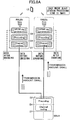
- Figs. 8A and 8B are views illustrating an operation example of a process of switching the function sharing in the DL.
- Figs. 8A and 8B illustrate an operation example in the case of using a processing load of the RAU 2 as a predetermined reference value. Note that, in Figs. 8A and 8B , a part of the plurality of kinds of signal processing of Layer 1, which are illustrated in Fig. 4B , is omitted. Boundaries "D2", “D4", and “D7” illustrated in Figs. 8A and 8B respectively correspond to the boundaries "D2", “D4", and "D7” illustrated in Fig. 4B . The boundaries illustrated in Figs.
- FIGS. 8A and 8B are illustrative only, and there is no limitation to the boundaries.
- the boundary “D2" in Figs. 8A and 8B may be the boundary “D3”
- the boundary "D4" in Figs. 8A and 8B may be the boundary "D6" or "D7”.
- the function sharing may be changed at any one of the boundaries "D1", and "D8" to "D10".
- the BBU 1 determines that the entirety of the plurality of signal processing according to Layer 1 are performed on the RAU 2a side and the RAU 2b side (determines that function sharing is made at the region "D7". Furthermore, BBU 1 transmits a DL signal that is subjected to the signal processing according to Layer 2 to the RAU 2a and the RAU 2b through the FH on the basis of the determination result.
- the BBU 1 may perform the transmission by applying a predetermined header to the DL signal, and by applying an identifier, which indicates that signal processing up to Layer 2 has been performed, to the header.
- the identifier which indicates that signal processing up to Layer 2 has been performed.
- the BBU 1 may be configured to transmit the DL signal, which is subjected to the signal processing according to Layer 2, to any one of the RAU 2a and the RAU 2b. According to this, it is possible to further reduce the amount of signals through the FH.
- the BBU 1 determines that among the plurality of kinds of signal processing according to Layer 1, processing up to resource element mapping is performed on the BBU 1 side (determines that function sharing is made at the region "D2"). In addition, the BBU 1 transmits the DL signal, which is subjected to the signal processing up to the resource element mapping, to the RAU 2a and the RAU 2b through the FH on the basis of the determination result.
- the BBU 1 may perform another precoding processing with respect to the DL signal to be transmitted to the RAU 2a and the DL signal to be transmitted to the RAU 2b on the basis of a propagation state (channel information and the like) of the DL signal between the RAU 2a and the RAU 2b, and the user equipment UE.
- the BBU 1 may perform the transmission by applying a predetermined header to the DL signal, and by applying an identifier, which indicates that signal processing up to the resource element mapping has been performed, to the header.
- a predetermined header to the DL signal
- an identifier which indicates that signal processing up to the resource element mapping has been performed, to the header.
- signal processing in accordance with OFDM signal generation is performed in the RAU 2a and the RAU 2b.
- the BBU 1 or the RAU 2 may stop scheduling of the DL and the UL for a predetermined period of time. According to this, it is possible to avoid a possibility that the function sharing is changed during transmission of the DL signal or the UL signal, and thus a signal is damaged.
- Fig. 9 is a view illustrating a functional configuration example of the BBU according to this embodiment.
- the BBU 1 includes an inter-RAU signal transmission unit 101, an inter-RAU signal reception unit 102, a higher layer processing unit 103, and a function sharing determination unit 104.
- Fig. 9 illustrates only function units, which particularly related to this embodiment, of the BBU 1, and the BBU 1 also has a function (not illustrated) of performing at least an operation in conformity to LTE (including 5G).
- the functional configuration illustrated in Fig. 9 is illustrative only. Function classification or the name of the function units may be arbitrary as long as the operation according to this embodiment can be executed.
- the inter-RAU signal transmission unit 101 has a function of performing signal processing with respect to a DL signal received from the higher layer processing unit 103 on the basis of function sharing as a notification from the function sharing determination unit 104 or the RAU 2 to generate a signal, and of transmitting the signal that is generated to the RAU 2 through the FH.
- the inter-RAU signal reception unit 102 has a function of performing signal processing with respect to an UL signal received from the RAU 2 through the FH on the basis of the function sharing as a notification from the function sharing determination unit 104 or the RAU 2, and of transmitting the resultant signal to the higher layer processing unit 103.
- the inter-RAU signal transmission unit 101 transmits the signal, which is subjected to the signal processing, to any one of a plurality of the RAUs 2 or the plurality of RAUs 2 (performs cooperative transmission).
- the inter-RAU signal reception unit 102 performs signal processing by using one signal or a plurality of signals among a plurality of signals which are subjected to the signal processing in the plurality of RAUs 2 (performs cooperative reception).
- the inter-RAU signal transmission unit 101 and the inter-RAU signal reception unit 102 include a function as an interface of a predetermined protocol that is used in the FH.
- the higher layer processing unit 103 includes a function of performing signal processing on and above Layer 2, and a function of transmitting, to a core network, etc., a signal to which the signal processing up to Layer 2 or the signal processing above Layer 2 is applied.
- the function sharing determination unit 104 includes a function of determining allocation of signal processing that is performed by the RAU 2 and signal processing that is performed by the BBU 1 on the basis of a predetermined reference value.
- the inter-RAU signal transmission unit 101 is classified into a PDCP processing unit 1011 as a processing unit that performs signal processing of the DL of Layer 2, an RLC processing unit 1012, a MAC processing unit 1013, a channel coding unit 1014 as a processing unit that performs signal processing of the DL of Layer 1, a modulation unit 1015, a layer mapping unit 1016, a precoding unit 1017, a resource mapping unit 1018, and an OFDM signal generation unit 1019.
- the inter-RAU signal transmission unit 101 includes an output unit 1010.
- the PDCP processing unit 1011 performs various kinds of processing in accordance with a PDCP sub-layer.
- the RLC processing unit 1012 performs various kinds of processing in accordance with the RLC sub-layer.
- the MAC processing unit 1013 performs various kinds of processing in accordance with a MAC sub-layer.
- the channel coding unit 1014 performs processing such as application of CRC, code block division, and rate matching with respect to the DL signal received from the higher layer processing unit 103.
- the modulation unit 1015 modulates a bit stream by using a predetermined modulation method.
- the layer mapping unit 1016 maps a modulation symbol to respective layers.
- the precoding unit 1017 performs precoding processing with respect to the modulation symbol of the respective layers to map the modulation symbol of the respective layers to respective antenna ports.
- the resource mapping unit 1018 maps the modulation symbol, which is transmitted from the respective antenna ports, to a predetermined resource element.
- the OFDM signal generation unit 1019 performs IFFT processing with respect to a signal of a frequency region that is mapped to a resource element to generate an OFDM signal.
- the output unit 1010 extracts a signal, which is generated by any one of the higher layer processing unit 103, the PDCP processing unit 1011, the RLC processing unit 1012, the MAC processing unit 1013, the channel coding unit 1014, the modulation unit 1015, the layer mapping unit 1016, the precoding unit 1017, the resource mapping unit 1018, and the OFDM signal generation unit 1019, on the basis of the function sharing as a notification from the function sharing determination unit 104 or the RAU 2, and transmits the signal to the RAU 2.
- the inter-RAU signal reception unit 102 is classified into an FFT processing unit 1021 as a processing unit that performs signal processing of the UL of Layer 1, a resource demapping unit 1022, a signal detection unit 1023, a demodulation unit 1024, a decoding unit 1025, a MAC processing unit 1026 as a processing unit that performs signal processing of the UL of Layer 2, an RLC processing unit 1027, and a PDCP processing unit 1028.
- the inter-RAU signal reception unit 102 includes an input unit 1020.
- the FFT processing unit 1021 performs removal of CP and FFT processing with respect to an UL signal that is received.
- the resource demapping unit 1022 extracts a modulation symbol, which is scheduled to respective pieces of a user equipment UE, from a modulation symbol that is subjected to the FFT processing.
- the signal detection unit 1023 separates a spatial multiplex modulation symbol for each layer. Furthermore, for example, the signal detection unit 1023 may perform signal detection by using MLD, and the like.
- the demodulation unit 1024 demodulates a bit stream from the modulation symbol that is detected.
- the decoding unit 1025 performs processing of decoding the bit stream that is demodulated.
- the MAC processing unit 1026 performs various kinds of processing in accordance with a MAC sub-layer.
- the RLC processing unit 1027 performs various kinds of processing in accordance with an RLC sub-layer.
- the PDCP processing unit 1028 performs various kinds of processing in accordance with a PDCP sub-layer.
- the input unit 1020 transmits the UL signal, which is received from the RAU 2, to any one of the FFT processing unit 1021, the resource demapping unit 1022, the signal detection unit 1023, the demodulation unit 1024, the decoding unit 1025, the MAC processing unit 1026, the RLC processing unit 1027, the PDCP processing unit 1028, and the higher layer processing unit 103 on the basis of the function sharing as a notification from the function sharing determination unit 104 or the RAU 2.
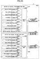
- Fig. 10 is a view illustrating a functional configuration example of the RAU in accordance with this embodiment.
- the RAU 2 includes an inter-UE signal transmission unit 201, an inter-UE signal reception unit 202, an inter-BBU signal reception unit 203, an inter-BBU signal transmission unit 204, and a function sharing determination unit 205.
- Fig. 10 illustrates only function units, which particularly related to this embodiment, of the RAU 2, and the RAU 2 also has a function (not illustrated) of performing at least an operation in conformity to LTE (including 5G).
- the functional configuration illustrated in Fig. 10 is illustrative only. Function classification or the name of the function units may be arbitrary as long as the operation according to this embodiment can be executed.
- the inter-UE signal transmission unit 201 includes a function of performing signal processing with respect to a DL signal received from the inter-BBU signal reception unit 203 on the basis of function sharing as a notification from the function sharing determination unit 205 or the BBU 1 to generate a signal, and of transmitting the signal that is generated to the user equipment UE.
- the inter-UE signal reception unit 202 includes a function of performing signal processing with respect to an UL signal received from the user equipment UE on the basis of the function sharing as a notification from the function sharing determination unit 205 or the BBU 1, and of transmitting the signal to the inter-BBU signal transmission unit 204.
- the inter-BBU signal reception unit 203 and the inter-BBU signal transmission unit 204 include a function of transmitting and receiving a signal to and from the BBU 1, and a function as an interface of a predetermined protocol that is used in the FH.
- the function sharing determination unit 205 includes a function of determining allocation of signal processing that is performed by the RAU 2 and signal processing that is performed by the BBU 1 on the basis of a predetermined reference value.
- the inter-UE signal transmission unit 201 is classified into a PDCP processing unit 2011 as a processing unit that performs signal processing of the DL of Layer 2, an RLC processing unit 2012, a MAC processing unit 2013, a channel coding unit 2014 as a processing unit that performs signal processing of the DL of Layer 1, a modulation unit 2015, a layer mapping unit 2016, a precoding unit 2017, a resource mapping unit 2018, and OFDM signal generation unit 2019.
- the inter-UE signal transmission unit 201 includes an input unit 2010.
- the PDCP processing unit 2011, the RLC processing unit 2012, the MAC processing unit 2013, the channel coding unit 2014, the modulation unit 2015, the layer mapping unit 2016, the precoding unit 2017, the resource mapping unit 2018, and the OFDM signal generation unit 2019 are respectively the same as the PDCP processing unit 1011, the RLC processing unit 1012, the MAC processing unit 1013, the channel coding unit 1014, the modulation unit 1015, the layer mapping unit 1016, the precoding unit 1017, the resource mapping unit 1018, and the OFDM signal generation unit 1019 of the BBU 1, and thus description thereof will be omitted.
- the input unit 2010 transmits a DL signal received from the inter-BBU signal reception unit 203 to any one of the PDCP processing unit 2011, the RLC processing unit 2012, the MAC processing unit 2013, the channel coding unit 2014, the modulation unit 2015, the layer mapping unit 2016, the precoding unit 2017, the resource mapping unit 2018, and the OFDM signal generation unit 2019 on the basis of function sharing as a notification from the function sharing determination unit 205 or the BBU 1.
- the inter-UE signal reception unit 202 is classified into an FFT processing unit 2021 as a processing unit that performs signal processing of the UL of Layer 1, a resource demapping unit 2022, a signal detection unit 2023, a demodulation unit 2024, a decoding unit 2025, a MAC processing unit 2026 as a processing unit that performs signal processing of the UL of Layer 2, an RLC processing unit 2027, and a PDCP processing unit 2028.
- the inter-UE signal reception unit 202 includes an output unit 2020.
- the FFT processing unit 2021, the resource demapping unit 2022, the signal detection unit 2023, the demodulation unit 2024, the decoding unit 2025, the MAC processing unit 2026, the RLC processing unit 2027, and the PDCP processing unit 2028 are respectively the same as the FFT processing unit 1021, the resource demapping unit 1022, the signal detection unit 1023, the demodulation unit 1024, and the decoding unit 1025, the MAC processing unit 1026, the RLC processing unit 1027, and the PDCP processing unit 1028 of the BBU 1, and, thus, the description is omitted.
- the output unit 2020 extracts a signal, which is generated by any one of the FFT processing unit 2021, the resource demapping unit 2022, the signal detection unit 2023, the demodulation unit 2024, the decoding unit 2025, the MAC processing unit 2026, the RLC processing unit 2027, and the PDCP processing unit 2028, on the basis of the function sharing as a notification from the function sharing determination unit 205 or the BBU 1, and transmits the signal to the inter-BBU signal transmission unit 204.
- the entirety of the above-described functional configuration of the BBU 1 and the RAU 2 may be implemented by a hardware circuit (for example, one or a plurality of IC chips).
- a part of the functional configuration may be configured as a hardware circuit, and the other portions may be implemented by a CPU and a program.
- Fig. 11 is a view illustrating a hardware configuration example of the BBU according to this embodiment.
- Fig. 11 illustrates a configuration that is closer to a mounting example in comparison to Fig. 9 .
- the BBU 1 includes an inter-RAU IF 301 as an interface for connection to the RAU 2, a BB processing module 302 that performs dedicated line connection system signal processing, a device control module 303 that performs processing of a higher layer and the like, and a communication IF 304 as an interface for connection to a core network and the like.
- the inter-RAU IF 301 has a function of connecting physical lines of the FH that connects the BBU 1 and the RAU 2 to each other, and a function of terminating a protocol that is used in the FH.
- the inter-RAU IF 301 includes parts of the inter-RAU signal transmission unit 101 and the inter-RAU signal reception unit 102 which are illustrated in Fig. 9 .
- the BB processing module 302 performs processing of converting an IP packet and a signal that is transmitted and received to and from the RAU 2.
- a DSP 312 is a processor that performs signal processing in the BB processing module 302.
- a memory 322 is used as a work area of the DSP 312.
- the BB processing module 302 includes parts of the inter-RAU signal transmission unit 101 and the inter-RAU signal reception unit 102 which are illustrated in Fig. 9 , a part of the higher layer processing unit 103, and a part of the function sharing determination unit 104.
- the device control module 303 performs protocol processing of an IP layer, operation and maintenance processing (OAM), and the like.
- a processor 313 is a processor that performs processing that is performed by the device control module 303.
- the memory 323 is used as a work area of the processor 313.
- Examples of an auxiliary storage device 333 include an HDD, and the like, and the auxiliary storage device 333 stores various kinds of setting information for an operation of the base station eNB, and the like.
- the device control module 303 includes parts of the higher layer processing unit 103 and the function sharing determination unit 104 which are illustrated in Fig. 9 .
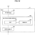
- Fig. 12 is a view illustrating a hardware configuration example of the RAU according to this embodiment.
- Fig. 12 illustrates a configuration that is closer to a mounting example in comparison to Fig. 10 .
- the RAU 2 includes a radio frequency (RF) module 401 that performs processing related to a radio signal, a base band (BB) processing module 402 that performs dedicated line connection system signal processing, and an inter-BBU IF 403 as an interface for connection to the BBU 1.
- RF radio frequency
- BB base band
- inter-BBU IF 403 as an interface for connection to the BBU 1.
- the RF module 401 performs digital-to-analog (D/A) conversion, orthogonal modulation, frequency conversion, power amplification, and the like with respect to a digital baseband signal received from the BB processing module 402 to generate a radio signal to be transmitted from an antenna.
- the RF module 401 performs frequency conversion, analog-to-digital (A/D) conversion, orthogonal demodulation, and the like with respect to a radio signal that is received to generate a digital baseband signal, and transmits the signal to the BB processing module 402.
- the RF module 401 includes an RF function.
- the RF module 401 includes parts of the inter-UE signal transmission unit 201 and the inter-UE signal reception unit 202 which are illustrated in Fig. 10 .
- the BB processing module 402 performs processing of converting a signal that is transmitted and received to and from the BBU 1 through the inter-BBU IF 403, and the digital baseband signal from each other.
- a digital signal processor (DSP) 412 is a processor that performs signal processing in the BB processing module 402.
- the memory 422 is used as a work area of the DSP 412.
- the BB processing module 402 includes parts of the inter-UE signal transmission unit 201 and the inter-UE signal reception unit 202, and the function sharing determination unit 205 which are illustrated in Fig. 10 .
- the inter-BBU IF 403 has a function of connecting physical lines of the FH that connects the BBU 1 and the RAU 2 to each other, and a function of terminating a protocol that is used in the FH.
- the inter-BBU IF 403 includes the inter-BBU signal reception unit 203 and the inter-BBU signal transmission unit 204 which are illustrated in Fig. 10 .
- a radio communication system including a first base station, a second base station, a third base station that performs a communication with the first base station and the second base station, and a user equipment that performs a communication with the first base station and the second base station, the radio communication system including a determination unit that determines allocation of signal processing that is commonly performed by the first base station and the second base station and signal processing that is performed by the third base station, based on a predetermined reference value; a first signal processor that performs the signal processing allocated to the first base station in accordance with the allocation that is determined by the determination unit; a second signal processor that performs the signal processing allocated to the second base station in accordance with the allocation that is determined by the determination unit; and a third signal processor that performs the signal processing allocated to the third base station in accordance with the allocation that is determined by the determination unit.
- the radio communication system there is provided a technology capable of appropriately changing function sharing between the BBU 1 and the RAU 2 in a radio communication network
- the predetermined reference value may be a CRC check success rate, an SINR, or an SNR of an uplink signal that is transmitted from the user equipment or a downlink signal that is received by the user equipment, the number of retransmission times of the uplink signal or the downlink signal, or a channel estimation error
- the determination unit may determine the allocation of the signal processing that is commonly performed by the first base station and the second base station and the signal processing that is performed by the third base station based on the CRC check success rate, the SINR, or the SNR of the uplink signal that is transmitted from the user equipment or the downlink signal that is received by the user equipment, the number of retransmission times of the uplink signal or the downlink signal, or the channel estimation error.
- the predetermined reference value may be a processing load on the first base station, a processing load on the second base station, or a processing load on the third base station
- the determination unit may determine the allocation of the signal processing that is commonly performed by the first base station and the second base station and the signal processing that is performed by the third base station on based on the processing load on the first base station, the processing load on the second base station, or the processing load on the third base station. According to this, it is possible to appropriately change the function sharing between the BBU 1 and the RAU 2 on the basis of the processing load of the RAU 2. In addition, it is possible to reduce the processing load of the RAU 2.
- the predetermined reference value may be information indicating whether at least one of the number of antennas of the first base station and the number of antennas of the second base station is greater than or equal to the number of antennas of the user equipment, and wherein the determination unit may determine the allocation of the signal processing that is commonly performed by the first base station and the second base station and the signal processing that is performed by the third base station based on whether at least one of the number of antennas of the first base station and the number of antennas of the second base station is greater than or equal to the number of antennas of the user equipment. According to this, it is possible to appropriately change the function sharing between the BBU 1 and the RAU 2 on the basis of the number of antennas provided to the user equipment UE and the number of antennas provided to the RAU 2.
- the determination unit may determine that entire layer 1 signal processing of the uplink signal is performed by the first signal processor of the first base station and the second signal processor of the second base, upon determining that the CRC check success rate, the SINR, or the SNR of the uplink signal that is transmitted from the user equipment or the downlink signal that is received by the user equipment is greater than or equal to a predetermined threshold value, upon determining that the number of retransmission times of the uplink signal that is transmitted from the user equipment or the downlink signal that is received by the user equipment is less than a predetermined threshold value, or upon determining that the channel estimation error of the uplink signal that is transmitted from the user equipment or the downlink signal that is received by the user equipment is less than a predetermined threshold value, and wherein the third signal processor may perform layer 2 signal processing using one of a signal that is processed by the first signal processor and a signal that is processed by the second signal processor. According to this, it is possible to determine whether or not to perform cooperative reception in the BBU 1 while reducing a transmission amount through the F
- the determination unit may determine that a part of the layer 1 signal processing of the uplink signal is performed by the first signal processor of the first base station and the second signal processor of the second base station and a remaining part of the layer 1 signal processing is performed by the third signal processor of the third base station upon determining that the CRC check success rate, the SINR, or the SNR of the uplink signal that is transmitted from the user equipment or the downlink signal that is received by the user equipment is less than a predetermined threshold value, upon determining that the number of retransmission times of the uplink signal that is transmitted from the user equipment or the downlink signal that is received by the user equipment is greater than or equal to a predetermined threshold value, or upon determining that the channel estimation error of the uplink signal that is transmitted from the user equipment or the downlink signal that is received by the user equipment is greater than or equal to a predetermined threshold value, and wherein the third signal processor may perform a remaining part of the layer 1 signal processing and layer 2 signal processing by using both of a signal that is processed by the first signal processor and
- a base station that is used as a third base station in a radio communication system including a first base station, a second base station, the third base station that performs a communication with the first base station and the second base station, and a user equipment that performs a communication with the first base station and the second base station, the base station including a determination unit that determines allocation of signal processing that is commonly performed by the first base station and the second base station and signal processing that is performed by the base station on the basis of a predetermined reference value; and a signal processor that performs the signal processing allocated to the base station in accordance with the allocation that is determined in the determination unit.
- this base station there is provided a technology capable of appropriately changing the function sharing between the BBU 1 and the RAU 2 in the radio communication network by the C-RAN.
- a base station that is used as a first base station in a radio communication system including the first base station, a second base station, a third base station that performs a communication with the first base station and the second base station, and a user equipment that performs a communication with the first base station and the second base station, the base station including a determination unit that determines allocation of signal processing that is commonly performed by the base station and the second base station and signal processing that is performed by the third base station based on a predetermined reference value; and a signal processor that performs the signal processing allocated to the base station in accordance with the allocation that is determined in the determination unit.
- this base station there is provided a technology capable of appropriately changing the function sharing between the BBU 1 and the RAU 2 in the radio communication network by the C-RAN.
- the configuration of the respective devices (the BBU 1 and the RAU 2) described in the embodiment of the invention may be a configuration that is implemented when a program is executed by a processor (CPU) in the device including the CPU and a memory, or a configuration that is implemented by hardware such as a hardware circuit including a logic of the processing described in this embodiment.
- the program or the hardware may coexist.
- Operations of a plurality of function units may be performed physically with one component, or an operation of one function unit may be performed physically with a plurality of components.
- the order thereof may be changed as long as inconsistency does not occur.
- the BBU1 and the RAU 2 have been described by using functional block diagrams for convenience of processing description, but the devices may be implemented by hardware, software, or a combination thereof.
- RAM random access memory
- ROM read only memory
- EPROM EPROM
- EEPROM electrically erasable programmable read-only memory
- register a hard disk drive
- HDD hard disk drive
- removable disk a CD-ROM
- database a database
- server or other appropriate storage media.
- the first base station and the second base station in this embodiment are examples of the RAU 2.
- the third base station is an example of the BBU 1.
- the function sharing determination unit 104 or the function sharing determination unit 205 is an example of the determination unit.
- the inter-UE signal transmission unit 201 or the inter-UE signal reception unit 202 is an example of the first signal processing unit and the second signal processing unit.
- the inter-RAU signal transmission unit 101 or the inter-RAU signal reception unit 102 is an example of the third signal processing unit.
- reporting of information is not limited to the aspects/embodiments described in this specification, and may be performed by another method.
- reporting of information may be implemented by physical layer signaling (e.g., DCI (Downlink Control Information)), UCI (Uplink Control Information)), higher layer signaling (e.g., RRC signaling, MAC signaling, broadcast information (MIB (Master Information Block), SIB (System Information Block)), other signals or a combination thereof.
- the RRC message may be referred to as RRC signaling.
- the RRC message may be, for example, an RRC connection setup (RRC Connection Setup) message, an RRC connection reconfiguration (RRC Connection Reconfiguration) message, and so forth.
- LTE Long Term Evolution
- LTE-A Long Term Evolution-Advanced
- SUPER 3G IMT-Advanced
- 4G 5G
- FRA Full Radio Access
- W-CDMA registered trademark
- GSM registered trademark
- CDMA 2000 UMB (Ultra Mobile Broadband); IEEE 802.11 (Wi-Fi); IEEE 802.16 (WiMAX); IEEE 802.20; UWB (Ultra-Wide Band); Bluetooth (registered trademark); a system that utilizes another suitable system and/or a next generation system evolved based on these.
- the decision or determination may be performed by a value (0 or 1) represented by one bit; may be performed by a Boolean value (Boolean: true or false); or by numerical value comparison (e.g., a comparison with a predetermined value).
- a channel and/or a symbol may be a signal (signal).
- a signal may be a message.
- the UE may be referred to, by a person skilled in the art, as a subscriber station; a mobile unit; a subscriber unit; a wireless unit; a remote unit; a mobile device; a wireless device; a wireless communication device; a remote device; a mobile subscriber station; an access terminal; a mobile terminal; a wireless terminal; a remote terminal; a handset; a user agent; a mobile client; a client; or some other suitable terms.
- reporting of predetermined information is not limited to the method of explicitly performing, and may be performed implicitly (e.g., not perform reporting of the predetermined information).
- the terms “determine (determining)” and “decide (determining)” may encompass a wide variety of operations.
- the “determine” and “decide” may include, for example, “determine” and “decide” what is calculated (calculating), computed (computing), processed (processing), derived (deriving), investigated (investigating), looked up (looking up) (e.g., looked up in tables, databases, or other data structures), ascertained (ascertaining).
- the "determine” and “decide” may include deeming that “determination” and “decision” are made on reception (receiving) (e.g., receiving information), transmission (transmitting) (e.g., transmitting information), input (input), output (output), and access (accessing) (e.g., accessing data in a memory). Furthermore, the “determine” and “decide” may include deeming that "determination” and “decision” are made on what is resolved (resolving), selected (selecting), chosen (choosing), established (establishing), and compared (comparing). Namely, the "determine” and “decide” may include deeming that some operation is “determined” or "decided.”
- the input/output information, etc. may be stored in a specific location (e.g., a memory), or managed in a management table.
- the input/output information, etc. may be overwritten, updated, or additionally written.
- the output information, etc. may be deleted.
- the input information, etc. may be transmitted to another device.
- Reporting of predetermined information is not limited to the method of explicitly performing, and may be implicitly performed (e.g., reporting of the predetermined information is not performed).
- the information signals, etc. described in the specification may be represented by using any of a variety of different techniques.
- the data, indication, command, information, signal, bit, symbol, chip, etc. may be represented by a voltage, an electric current, an electromagnetic wave, a magnetic field or magnetic particles, a light field or photons, or any combination thereof.
Landscapes
- Engineering & Computer Science (AREA)
- Computer Networks & Wireless Communication (AREA)
- Signal Processing (AREA)
- Quality & Reliability (AREA)
- Mobile Radio Communication Systems (AREA)
- Radio Transmission System (AREA)
Abstract
Description
- An aspect of the present disclosure relates to a radio communication system and a base station.
- In a radio communication system of Long Term Evolution (LTE) and LTE-Advanced (LTE-A), there is known a technology called a centralized radio access network (C-RAN) capable of accommodating a plurality of cells while suppressing a device cost so as to efficiently support an area such as a high-traffic hot spot.
- The C-RAN is formed of one or a plurality of remote antenna units (RAUs) which are remote installation type base stations (slave station), and a baseband unit (BBU) that is a base station (master station) that concentrically controls the RAU. The BBU has a function of
Layer 1 to Layer 3 which are provided to the base station. A digital baseband signal, which is generated in the BBU, is transmitted to the RAU, and is transmitted from a radio frequency (RF) function unit provided to the RAU. - A network line that connects the BBU and the RAU is called a front haul (FH), and a common public radio interface (CPRI) is used as the FH in the LTE.
- Non-Patent Document 1: "Docomo 5G white paper", September, 2014, NTT Docomo, Internet URL: https: //www.nttdocomo.co.jp/corporate/technology/whitepaper_5g/
- In the current LTE, the functions of Layer 1 (physical layer: L1), Layer 2 (MAC, RLC, PDCP), and Layer 3 (RRC) are implemented on a BBU side. Accordingly, a band, which is necessary for the FH in the case of using 2×2 multiple input multiple output (MIMO), is approximately 16 times greater than a peak rate that is supported in the BBU. For example, as illustrated in
Fig. 1 , in a case where a system band is 20 MHz, and the BBU supports a radio communication (maximum: 150 Mbps) of 2×2 MIMO, a band necessary for the CPRI is approximately 2.5 Gbps. In addition, in this configuration, the band necessary for the CPRI increments in proportion to an increase in the number of antennas and the system band. - When 5G, which has been currently studied, is introduced, the band necessary for the FH significantly increases in accordance with an improvement in a peak rate. In the case of realizing a peak rate of 10 Gbps, the band necessary for the CPRI is several hundreds of Gbps or greater, and thus it is difficult to cope with a current CPRI standard (maximum: 24.33 Gbps).
- Here, an examination has been conducted to reduce a transmission amount through the FH by realizing a part of the layers mounted in the BBU on an RAU side. Various variations have been studied with respect to function sharing between the BBU and RAU. As an example thereof, a plan in which the entirety of a plurality of kinds of processing of
Layer 1 are implemented in RAU, and processing ofLayer 2 or higher is implemented in the BBU, a plan in which a part of the processing ofLayer 1 is implemented on the RAU side, the remaining processing ofLayer 1 and the processing ofLayer 2 or higher are implemented on the BBU side, and the like have been studied. - In addition, application of a network such as a passive optical network (PON) in which one optical fiber is shared by multiple nodes and Ethernet (registered trademark) to the FH has been studied (
Fig. 2 ) to implement the FH that is cheaper than the CPRI. The networks are shared by the multiple nodes, and thus it is considered that a control of a transmission amount through the FH is necessary in correspondence with a variation of a signal quantity between the nodes. - In addition, it is assumed that processing capability of the RAU is relatively lower than that of the BBU. Accordingly, when simply reducing the transmission amount of the FH, a processing load of the RAU tends to increase. Accordingly, there is a need for a structure capable of appropriately changing the function sharing between the BBU and the RAU in correspondence with a situation in consideration of the processing load of the RAU, communication quality with a user equipment, and the like.
- A disclosed technology has been made in consideration of the above-described situations, and an object thereof is to provide a technology capable of appropriately changing function sharing between a BBU and an RAU in a radio communication network according to a C-RAN.
- According to an aspect of the present disclosure, there is provided a radio communication system including a first base station, a second base station, a third base station that performs a communication with the first base station and the second base station, and a user equipment that performs a communication with the first base station and the second base station. The radio communication system includes a determination unit that determines allocation of signal processing that is commonly performed by the first base station and the second base station and signal processing that is performed by the third base station, based on a predetermined reference value; a first signal processor that performs the signal processing allocated to the first base station in accordance with the allocation that is determined by the determination unit; a second signal processor that performs the signal processing allocated to the second base station in accordance with the allocation that is determined by the determination unit; and a third signal processor that performs the signal processing allocated to the third base station in accordance with the allocation that is determined by the determination unit.
- According to an aspect of the present disclosure, a technology is provided that is capable of appropriately changing function sharing between a BBU and an RAU in a radio communication network according to a C-RAN.
-
-
Fig. 1 is a view illustrating a band necessary for an FH; -
Fig. 2 is a view illustrating an example of a network whose use for FH is being considered; -
Fig. 3 is a view illustrating a system configuration example of a radio communication system according to an embodiment; -
Fig. 4A is a view illustrating a function sharing example between a BBU and an RAU in a UL; -
Fig. 4B is a view illustrating a function sharing example between a BBU and an RAU in a DL; -
Fig. 5 is a sequence diagram illustrating an example of a procedure when changing the function sharing in the UL; -
Fig. 6 is a sequence diagram illustrating an example of a procedure when changing the function sharing in the DL; -
Fig. 7A is a view illustrating an operation example of a process for switching a functional share in the UL; -
Fig. 7B is a view illustrating an operation example of a process for switching a functional share in the UL; -
Fig. 8A is a view illustrating an operation example of the process for switching the functional share in the DL; -
Fig. 8B is a view illustrating an operation example of the process for switching the functional share in the DL; -
Fig. 9 is a view illustrating a functional configuration example of the BBU according to the embodiment; -
Fig. 10 is a view illustrating a functional configuration example of the RAU according to the embodiment; -
Fig. 11 is a view illustrating a hardware configuration example of the BBU according to the embodiment; and -
Fig. 12 is a view illustrating a hardware configuration example of the RAU according to the embodiment. - Hereinafter, an embodiment of the invention is described by referring to the accompanying drawings. Note that, the following embodiment is illustrative only, and an embodiment to which the invention is applicable is not limited to the following embodiment. For example, in a radio communication system according to this embodiment, a system of a method in conformity to an LTE or 5G is assumed, but the invention is applicable to other methods without limitation to the LTE or 5G. Furthermore, in this specification and claims, "LTE" is used in wide meaning including not only a communication method corresponding to Release 8 or 9 of 3GPP but also a corresponding fifth generation communication method subsequently to Release 10, 11, 12, 13, or 14 of 3GPP.
-
Fig. 3 is a view illustrating a system configuration example of the radio communication system according to the embodiment. As illustrated inFig. 3 , the radio communication system according to this embodiment includes aBBU 1, anRAU 2a, anRAU 2b, and a user equipment UE. In the following description, in the case of not discriminating theRAU 2a and theRAU 2b, theRAU 2a and theRAU 2b will be described as "RAU 2". InFig. 3 theRAU 2a and theRAU 2b are illustrated, but three or greater ofRAUs 2 may be included. - The BBU 1 may be referred to as an aggregate base station, a master station, or a base station (enhanced Node B (eNB)) in a simple manner. The RAU 2 may be referred to as a satellite base station, a slave station, or a base station in a simple manner. The
BBU 1 and theRAU 2 transmits and receives a predetermined signal through an FH. - In addition, the
BBU 1 performs a control so that theRAU 2a and theRAU 2b transmits (cooperatively transmits) a DL signal to a user equipment UE in cooperation with each other. Similarly, theBBU 1 performs a control so that composition, selection, and the like of a UL signal, which is received from each of theRAU 2a and theRAU 2b, are performed to receive (cooperatively receive) the UL signal from the user equipment UE on theBBU 1 side in a cooperative manner. -
Figs. 4A and4B are views illustrating a function sharing example between a BBU and an RAU.Fig. 4A illustrates a function sharing example in a UL, andFig. 4B illustrates a function sharing example in a DL. Boundaries "U1" to "U9" inFig. 4A represent boundaries of a plurality of kinds of processing of UL which are respectively performed in theBBU 1 and theRAU 2. For example, in the case of function sharing in the boundary "U6", processing according to a function ofLayer 2 or higher is performed on aBBU 1 side, and processing according to a function ofLayer 1 is performed on anRAU 2 side. Furthermore, for example, in the case of function sharing at the boundary "U2", among a plurality of kinds of processing according to the function ofLayer 1, processing up to an FFT is performed on theRAU 2 side, and processing subsequent to resource demapping (resource element demapping) is performed on theBBU 1 side. The boundary "U1" corresponds to a configuration of connecting theBBU 1 and theRAU 2 by using a CPRI. Furthermore, in a case where a communication by an MIMO is not performed in the UL, signal detection processing is omitted. - Similarly, boundaries "D1" to "D10" in
Fig. 4B represent boundaries of a plurality of kinds of processing of the DL which are respectively performed in theBBU 1 and theRAU 2. For example, in the case of function sharing at the boundary "D7", processing according to the function ofLayer 2 or higher is performed on theBBU 1 side, and processing according to the function ofLayer 1 is performed on theRAU 2 side. In addition, for example, in the case of function sharing at the boundary "D2", among the plurality of kinds of processing according to the function ofLayer 1, processing up to resource element mapping is performed on theBBU 1 side, and OFDM signal generation is performed on theRAU 2 side. The boundary "D1" corresponds to a configuration of connecting theBBU 1 and theRAU 2 by using the CPRI. Furthermore, in a case where a communication by the MIMO is not performed in the DL, processing layer mapper and processing of precoding are not performed. - The
BBU 1, theRAU 2a, and theRAU 2b according to this embodiment are capable of arbitrarily changing that the function sharing is to be made (signal processing is to be shared) at which boundary among boundaries "U1" to "U9" in an UL. Similarly, theBBU 1, theRAU 2a, and theRAU 2b according to this embodiment are capable of arbitrarily changing that the function sharing is to be made (signal processing is to be shared) at which boundary among boundaries "D1" to "D10" in a DL. Furthermore, theBBU 1, theRAU 2a, and theRAU 2b according to this embodiment may be configured to commonly change the function sharing in a unit of theRAU 2a and theRAU 2b (in other words, the same function sharing may be allowed to be made in theRAU 2a and theRAU 2b), or to commonly change the function sharing in a unit of the user equipment UE (in other words, the same function sharing may be allowed to be made with respect to the same user equipment UE). In addition, the function sharing may be changed independently in the UL and the DL. -
Fig. 5 is a sequence diagram illustrating an example of a procedure for switching function sharing in the UL. - In step S101, the
BBU 1 or theRAU 2 determine sharing (determine function sharing) between signal processing performed by theBBU 1 and signal processing performed by the RAU 2 (signal processing that is commonly performed by theRAU 2a and theRAU 2b). In this embodiment, the boundaries ("U1" to "U9") of the function sharing between theBBU 1 and theRAU 2 may be determined in theBBU 1 or theRAU 2. - More specifically, the
BBU 1 or theRAU 2 determines allocation of signal processing performed by theRAU 2 and signal processing performed by theBBU 1 on the basis of a predetermined reference value. For example, a table, in which a range of a predetermined reference value and the boundaries "U1" to "U9" in the UL are correlated one-to-one, is retained in theBBU 1 or theRAU 2. TheBBU 1 or theRAU 2 may determine allocation of the signal processing performed by theRAU 2 and the signal processing performed by theBBU 1 by comparing the table and the predetermined reference value with each other. In addition, a predetermined threshold value may be retained in theBBU 1 or theRAU 2, and theBBU 1 or theRAU 2 may determine that the function sharing is to be made at which boundary among the boundaries "U1" to "U9" through determination of whether or not the predetermined reference value is equal to or greater than the predetermined threshold value. Acquisition (measurement) of the predetermined reference value may be performed by theBBU 1 or theRAU 2. TheBBU 1 or theRAU 2 may notify a counterpart (theRAU 2 or the BBU 1) of an acquisition result (or measurement result) as necessary. A specific example of the predetermined reference value will be described later. - The
BBU 1 or theRAU 2 notifies a counterpart (theRAU 2 or the BBU 1) of the determination result of the function sharing. Furthermore, in a case where theRAU 2 makes a determination of the function sharing, the notification of the determination result of the function sharing is made between theRAU 2a and theRAU 2b. In addition, in a case where theRAU 2 makes a determination of the function sharing, theRAU 2a and theRAU 2b may apply an identifier, which indicates that signal processing according to which function has been performed on theRAU 2a side or on theRAU 2b side, to header information of a UL signal that is transmitted in a procedure in step S113a and step S113b to be described later. According to this, the function sharing of the UL can be changed in a dynamic manner. - In step S111a, the
RAU 2a receives an UL signal that is transmitted from the user equipment UE. Similarly, in step S11b, theRAU 2b receives an UL signal that is transmitted from the user equipment UE. Subsequently, theRAU 2a performs signal processing to be performed by theRAU 2a (S112a), and transmits a signal after being subjected to the signal processing to the BBU 1 (S113a). Similarly, theRAU 2b performs signal processing to be performed by theRAU 2b (S112b), and transmits a signal after being subjected to the signal processing to the BBU 1 (S113b). - In step S114, the
BBU 1 performs signal processing to be performed by the BBU 1 (S114). Here, theBBU 1 performs cooperative reception by using the UL signal transmitted from theRAU 2a and the UL signal transmitted from theRAU 2b. A method of performing the cooperative reception may be any method. For example, theBBU 1 may select a UL signal from any one side among UL signals received from theRAU 2a and UL signals received from theRAU 2b, or may combine and receive the UL signals from the both sides. In addition, in the case of selecting a UL signal from any one side, theBBU 1 may measure reception quality (SNR, SINR, and the like) of the UL signals from theRAU 2a and theRAU 2b to select a UL signal in which reception quality of the UL signal is satisfactory. - Furthermore, the procedure in step S101 to S114 described above may be repetitively performed with a predetermined interval. According to this, for example, the function sharing of the UL can be switched in a dynamic manner on the basis of a variation in reception quality of the UL signal or a DL signal, a variation in a processing load of the
RAU 2, and the like. -
Fig. 6 is a sequence diagram illustrating an example of a procedure for switching function sharing in the DL. Furthermore, in this embodiment, the boundaries "D1" to "D10" of function sharing between theBBU 1 and theRAU 2 may be determined in theBBU 1 or theRAU 2. - In step S201, the
BBU 1 or theRAU 2 determines sharing (determines function sharing) between signal processing performed by theBBU 1 and signal processing performed by the RAU 2 (signal processing that is commonly performed by theRAU 2a andRAU 2b). In this embodiment, the boundaries ("D1" to "D10") of the function sharing between theBBU 1 and theRAU 2 may be determined in theBBU 1 or theRAU 2. - More specifically, the
BBU 1 or theRAU 2 determines allocation of signal processing performed by theRAU 2 and signal processing performed by theBBU 1 on the basis of a predetermined reference value. For example, a table, in which a range of a predetermined reference value and the boundaries "D1" to "D10" in the DL are correlated one-to-one, is retained in theBBU 1 or theRAU 2. TheBBU 1 or theRAU 2 may determine allocation of the signal processing performed by theRAU 2 and the signal processing performed by theBBU 1 by comparing the table and the predetermined reference value with each other. In addition, a predetermined threshold value may be retained in theBBU 1 or theRAU 2, and theBBU 1 or theRAU 2 may determine that the function sharing is to be made at which boundary among the boundaries "D1" to "D10" through determination of whether or not the predetermined reference value is equal to or greater than the predetermined threshold value. Acquisition (measurement) of the predetermined reference value may be performed by theBBU 1 or theRAU 2. TheBBU 1 or theRAU 2 may notify a counterpart (theRAU 2 or the BBU 1) of an acquisition result (or measurement result) as necessary. - The
BBU 1 or theRAU 2 notifies a counterpart (theRAU 2 or the BBU 1) of the determination result of the function sharing. Furthermore, in a case where theRAU 2 determines the function sharing, the determination may be made by both of theRAU 2a and theRAU 2b or the determination may be made by any one of theRAU 2a and theRAU 2b, and a counterpart (theRAU 2b or theRAU 2a) may be notified of the determination result. In addition, in a case where theBBU 1 determines the function sharing, theBBU 1 may apply an identifier, which indicates that signal processing according to which function has been performed on theBBU 1 side, to header information of a DL signal that is transmitted in a procedure of step S211 to be described later. According to this, the function sharing of the DL can be switched in a dynamic manner. - The
BBU 1 performs signal processing to be performed by theBBU 1 with respect to a DL signal to be transmitted to the user equipment UE (S211), and transmits the DL signal after being subjected to the signal processing to theRAU 2a and theRAU 2b (S212a, S212b). Here, theBBU 1 performs a control so that theRAU 2a and theRAU 2b transmit (cooperatively transmit) the DL signal to the user equipment UE in cooperation with each other in a procedure of step S211. For example, theBBU 1 may be allowed to transmit a signal that is generated to both of theRAU 2a and theRAU 2b, or may be allowed to transmit the DL signal to any one of theRAU 2a and theRAU 2b. In a case where any one of theRAU 2a and theRAU 2b is selected, reception quality of the DL signal between the user equipment UE and theRAU 2a and reception quality of the DL signal between the user equipment UE and theRAU 2b may be allowed to be fed back from the user equipment UE to theBBU 1, and theBBU 1 may allowed to select theRAU 2 in which the reception quality is satisfactory. In addition, theBBU 1 may allow the user equipment UE to feed back a DL signal propagation state (for example, channel information and the like) between the user equipment UE and theRAU 2a and theRAU 2b to theBBU 1, and theBBU 1 may be allowed to generate a DL signal to be transmitted to theRAU 2a and a DL signal to be transmitted to theRAU 2b on the basis of the propagation state that is fed back and may be allowed to transmit the DL signals which are generated to theRAU 2a and theRAU 2b, respectively. - Subsequently, the
RAU 2a and theRAU 2b respectively perform signal processing to be performed by theRAU 2a or theRAU 2b on the basis of function sharing (S213a, S213b), and respectively transmit DL signals after being subjected to the signal processing to the user equipment UE (S214a, S214b). - Furthermore, the procedure of step S201 to S214 described above may be repetitively performed with a predetermined interval. According to this, for example, the function sharing of the DL can be changed in a dynamic manner on the basis of a variation in reception quality of the UL signal or the DL signal, a variation in a processing load of the
RAU 2, and the like. - For example, the predetermined reference value may be a value of a signal to interference plus noise power ratio (SINR) or a signal to noise ratio (SNR) of the UL signal received from the user equipment UE or the DL signal that is received by a user equipment UE. As a table in which a range of the SINR or the SNR and the boundaries in the UL or the DL are correlated with each other, for example, a table, in which correlation of (boundaries "U9", "U8", "U7", "U6", "U5", "U4", "U3", "U2", and "U1") or (boundaries "D10", "D9", "D8", "D7", "D6", "D5", "D4", "D3", "D2", and "D1") is made in the order from a side in which the range of the SINR or the SNR is great, may be used. That is, as the SINR or the SNR becomes greater, the number of processing performed on the
RAU 2 side may be set to increase. In addition, as another example, in a case where the SINR or the SNR is equal to or greater than a predetermined threshold value, the function sharing may be divided at a predetermined boundary in the UL or the DL (for example, the function sharing may be divided at "U6", "D7", and the like), and in a case where the SINR or the SNR is less than the predetermined threshold value, the function sharing may be divided at a predetermined boundary (for example, "U2", "D2", and the like) in the UL or the DL. - Acquisition (measurement) of the SINR or the SNR may be performed in the
RAU 2 or theBBU 1. In addition, in a case where the measurement is performed in theRAU 2, a side, in which an SINR or an SNR which is measured in theRAU 2a and an SINR or an SNR which is measured in theRAU 2b is greater, may be selected and used. In addition, in a case where the function sharing is changed for each user equipment UE, theRAU 2 or theBBU 1 may acquire (measure) the SINR or the SNR for each user equipment UE on the basis of series of a reference signal or a resource position allocated to the user equipment UE. In this case, theRAU 2 may be notified of the series of the reference signal or the resource position allocated to the user equipment UE from theBBU 1 in advance. In addition, in the case of changing the function sharing for unit of theRAU 2, for example, the changing of the function sharing per unit of theRAU 2 may be implemented by dividing scheduling time of a radio resource of the DL or UL for each user equipment UE. - In addition, the predetermined reference value may be a cyclic redundancy check (CRC) check success rate of the UL signal that is received from the user equipment UE or the DL signal that is received by the user equipment UE. The CRC check success rate represents a probability of determination as being correct in the CRC that is included in a radio signal transmitted with a predetermined physical channel. In a case where radio quality between the user equipment UE and the
RAU 2 deteriorates, the CRC check success rate decreases. - As a table in which a range of the CRC check success rate and the boundaries in the UL or the DL are correlated with each other, for example, a table, in which correlation of (boundaries "U9", "U8", "U7", "U6", "U5", "U4", "U3", "U2", and "U1") or (boundaries "D10", "D9", "D8", "D7", "D6", "D5", "D4", "D3", "D2", and "D1") is made in the order from a side in which a range of the CRC check success rate is high, may be used. That is, as the CRC check success rate is high, the number of processing performed on the
RAU 2 side may be set to increase. In addition, as another example, in a case where the CRC check success rate is equal to or greater than a predetermined threshold value, the function sharing may be divided at a predetermined boundary in the UL or the DL (for example, the function sharing may be divided at "U6", "D7", and the like), and in a case where the CRC check success rate is less than the predetermine threshold value, the function sharing may be divided at a predetermined boundary (for example, "U2", "D2", and the like) in the UL or the DL. - Acquisition (measurement) of the CRC check success rate may be performed by the
RAU 2 or theBBU 1. In addition, in a case where the measurement is performed by theRAU 2, a side, in which a CRC check success rate measured by theRAU 2a and a CRC check success rate measured by theRAU 2b is greater, may be selected and used. Furthermore, the CRC check is performed when performing decoding processing, and thus it is preferable that a device (BBU 1 or RAU 2), which performs processing according to the decoding, performs acquisition of the CRC check success rate. - In addition, the predetermined reference value may be the number of retransmission times of the UL signal or the DL signal from the user equipment UE in a predetermined period (or an average value of the number of retransmission times in the predetermined period). For example, the number of retransmission times of the DL signal to the user equipment UE in a predetermined period may be counted as the number of notification times of NAK by a PUCCH or a PUSCH.
- As a table in which a range of the number of retransmission times and the boundaries in the UL or the DL are correlated with each other, for example, a table, in which correlation of (boundaries "U9", "U8", "U7" "U6" "U5", "U4", "U3", "U2", and "U1") or (boundaries "D10", "D9", "D8", "D7", "D6", "D5", "D4", "D3", "D2", and "D1") is made in the order from a side in which a range of the number of retransmission times is small, may be used. That is, as the number of retransmission times is small, processing performed on the
RAU 2 side may be set to increase. In addition, as another example, in a case where the number of retransmission times is less than a predetermined threshold value, the function sharing may be divided at a predetermined boundary (for example, "U6", "D7", and the like) in the UL or the DL, and in a case where the number of retransmission times is equal to or greater than the predetermined threshold value, the function sharing may be divided at a predetermined boundary (for example, "U2", "D2", and the like) in the UL or the DL. - Acquisition (measurement) of the number of retransmission times may be performed in the
RAU 2 or theBBU 1. In addition, the measurement is performed by theRAU 2, an average value of the number of measurement times in theRAU 2a and the number of measurement times in theRAU 2b may be used, and a side, in which the number of measurement times is greater, may be selected and used. Furthermore, reception of the NAK is performed with a signal after being decoded, and thus it is preferable that the acquisition of the number of retransmission times is performed by a device (theBBU 1, theRAU 2a, or theRAU 2b) that performs processing in accordance with decoding. - In addition, the predetermined reference value may be a channel estimation error of the UL signal that is received from the user equipment UE or the DL signal that is received by the user equipment UE. The channel estimation error represents an index indicating that a variation (dispersion) occurs to a certain extent between an average value of results obtained by performing channel estimation by using a plurality of reference signals included in the UL signal that is received from the user equipment UE or the DL signal which the user equipment UE receives, and a result obtained by performing channel estimation of each of the reference signals. In a case where radio quality between the user equipment UE and the
RAU 2 deteriorates, the channel estimation error increases. - As a table in which a range of the channel estimation error and the boundaries in the UL or the DL are correlated with each other, for example, a table, in which correlation of (boundaries "U9", "U8", "U7", "U6", "U5", "U4", "U3", "U2", and "U1") or (boundaries "D10", "D9", "D8", "D7", "D6", "D5", "D4", "D3", "D2", and "D1") is made in the order from a side in which a range of the channel estimation error is small, may be used. That is, as the range of the channel estimation error is small, processing performed on the
RAU 2 side may be set to increase. In addition, as another example, in a case where the channel estimation error is less than a predetermined threshold value, the function sharing may be divided at a predetermined boundary (for example, "U6", "D7", and the like) in the UL or the DL, and in a case where the channel estimation error is equal to or greater than the predetermined threshold value, the function sharing may be divided at a predetermined boundary (for example, "U2", "D2", and the like) in the UL or the DL. - In addition, the predetermined reference value may be the magnitude of a processing load of the RAU 2 (a processor utilization rate, a memory utilization rate, the amount of data between the
BBU 1 and theRAU 2, and the like). With regard to the magnitude of the processing load of theRAU 2, a processing load of theRAU 2, which is the greatest between a processing load of theRAU 2a and a processing load of theRAU 2b, may be used. As a table in which a range of the magnitude of the processing load of theRAU 2 and the boundaries in the UL or the DL are correlated with each other, for example, a table, in which correlation of (boundaries "U1", "U2" "U3" "U4" "U5", "U6", "U7", "U8", and "U9") or (boundaries "D1" "D2" "D3" "D4", "D5", "D6", "D7", "D8", "D9", and "D10") is made in the order from a side in which a range of the processing load of theRAU 2 is great, may be used. That is, as the processing load of theRAU 2 is great, processing ofLayer 1, which is performed on theRAU 2 side, is set to decrease. In addition, as another example, in a case where the magnitude of the processing load of theRAU 2 is less than a predetermined threshold value, the function sharing may be divided at a predetermined boundary (for example, "U6", "D7", and the like) in the UL or the DL, and in a case where the magnitude of the processing load is equal to or greater than the predetermined threshold value, the function sharing may be divided at a predetermined boundary (for example, "U2", "D2", and the like) in the UL or the DL. - The processing load of the
RAU 2 may be measured by theRAU 2a and/or theRAU 2b, or may be estimated by theBBU 1 on the basis of the amount of data transmitted to theRAU 2a and/or theRAU 2b from theBBU 1, the amount of data that is scheduled by theBBU 1 with respect to theRAU 2a and/or theRAU 2b, and the like. - In addition, the predetermined reference value may relate to whether or not at least one of the number of antennas provided to the
RAU 2a and the number of antennas provided to theRAU 2b is equal to or greater than the number of antennas provided to the user equipment UE. For example, in a case where at least one of the number of antennas provided to theRAU 2a and the number of antennas provided to theRAU 2b is equal to or greater than the number of antennas provided to the user equipment UE, reception of the UL signal by using the MIMO is possible even in theRAU 2, and thus the function sharing may be made at a predetermined boundary (for example, "U6" and the like in the UL. In contrast, in a case where the number of antennas provided to each of theRAU 2a and theRAU 2b is smaller than the number of antennas provided to the user equipment UE, it is determined that it is necessary to perform reception of the UL signal by using the MIMO on theBBU 1 side, and the function sharing may be made at a predetermined boundary (for example, "U2" and the like). - Note that the number of the antennas included in the user equipment UE may be reported from the user equipment UE to the BBU1 by a higher layer, etc.
-
Figs. 7A and7B are views illustrating an operation example of function sharing changing processing in the UL.Figs. 7A and7B illustrate an operation example in the case of using the SINR as the predetermined reference value. Note that, inFigs. 7A and7B , a part of various kinds of signal processing ofLayer 1 as illustrated inFig. 4A is not illustrated, and boundaries "U2", "U4", and "U6" illustrated inFigs. 7A and7B respectively correspond to the boundaries "U2", "U4", and "U6" illustrated inFig. 4(a) . Note that the boundaries illustrated inFigs. 7A and7B are examples, and it is not intended to limit the boundaries. For example, the boundary "U2" inFigs. 7A and7B may be the boundary "U3", and the boundary "U4" inFigs. 7A and7B may be the boundary "U5". In addition, although not illustrated inFigs. 7A and7B , the function sharing may be changed at any one of boundaries "U1", and "U7" to "U9". - In addition, description is made on the assumption that the
BBU 1 has a function of measuring the SINR of the UL signal that is received from the user equipment UE, and determination of the function sharing is made on theBBU 1 side on the basis of the SINR measured in theBBU 1. - As illustrated in
Fig. 7A , in a case where the SINR of the UL signal received from the user equipment UE is equal to or greater than a predetermined threshold value, that is, reception quality of the UL signal is satisfactory, theBBU 1 determines that the entirety of a plurality of kinds of signal processing in accordance withLayer 1 are performed on theRAU 2a side and onRAU 2b side (determines that function sharing is made at the region "U6"). Subsequently, theBBU 1 notifies theRAU 2a and theRAU 2b of the determination result. - The
RAU 2a and theRAU 2b perform the entirety of the plurality of kinds of signal processing in accordance withLayer 1 on the basis of the determination result that is transmitted in the notification, and transmit a UL signal that is decoded to theBBU 1 through the FH. TheBBU 1 selects any one UL signal among UL signals which are received from theRAU 2a and theRAU 2b and are decoded, and performs signal processing subsequent toLayer 2 with respect to the UL signal that is selected. - On the other hand, as illustrated in
Fig. 7B , in a case where the SINR of the UL signal received from the user equipment UE is less than a predetermined threshold value, that is, in a case where reception quality of the UL signal is not satisfactory, theBBU 1 determines that among the plurality of kinds of signal processing according toLayer 1, processing up to FFT processing is performed on theRAU 2a side and theRAU 2b side, and the subsequent signal processing is performed on theBBU 1 side (determines that function sharing is made at the region "U2"). Then, theBBU 1 notifies theRAU 2a and theRAU 2b of the determination result. - The
RAU 2a and theRAU 2b perform signal processing up to the FFT processing among the plurality of kinds of signal processing according toLayer 1 on the basis of the determination result that is transmitted in the notification, and transmits the UL signal after the FFT processing to theBBU 1 through the FH. TheBBU 1 performs cooperative reception (for example, minimum mean squared error (MMSE) composition, composition by maximum likelihood detection (MLD), and the like) with respect to the UL signals which are received from theRAU 2a and theRAU 2b and are subjected to the FFT processing, and performs signal processing subsequent toLayer 2. - Furthermore, in the above-described operation example, in a case where function sharing is changed for each user equipment UE, the
BBU 1 may notify theRAU 2a and theRAU 2b of a determination result for each user equipment UE and information (for example, a radio resource position in a frequency direction, and the like) for identification of the user equipment UE in correlation with each other so that theRAU 2a and theRAU 2b can recognize that which radio resource is scheduled to which a user equipment UE on theRAU 2a side and theRAU 2b side. - According to this operation, in a case where reception quality of the UL signal received from the user equipment UE is satisfactory, the entirety of the plurality of kinds of signal processing of
Layer 1 are performed on theRAU 2 side, and thus it is possible to secure reception performance of the UL signal while reducing the transmission amount through the FH. Furthermore, since the transmission amount through the FH is reduced, it is possible to suppress occurrence of transmission delay. On the other hand, in a case where reception quality of the UL signal received from the user equipment UE is not satisfactory, the cooperative reception is performed on theBBU 1 side, and thus it is possible to secure reception performance of the UL signal. -
Figs. 8A and8B are views illustrating an operation example of a process of switching the function sharing in the DL.Figs. 8A and8B illustrate an operation example in the case of using a processing load of theRAU 2 as a predetermined reference value. Note that, inFigs. 8A and8B , a part of the plurality of kinds of signal processing ofLayer 1, which are illustrated inFig. 4B , is omitted. Boundaries "D2", "D4", and "D7" illustrated inFigs. 8A and8B respectively correspond to the boundaries "D2", "D4", and "D7" illustrated inFig. 4B . The boundaries illustrated inFigs. 8A and8B are illustrative only, and there is no limitation to the boundaries. For example, the boundary "D2" inFigs. 8A and8B may be the boundary "D3", and the boundary "D4" inFigs. 8A and8B may be the boundary "D6" or "D7". In addition, although not illustrated inFigs. 8A and8B , the function sharing may be changed at any one of the boundaries "D1", and "D8" to "D10". - In the example of
Figs. 8A and8B , description is made on the assumption that theRAU 2a (or theRAU 2b) measures a processing load thereof and notifies theBBU 1 of the processing load, and the function sharing is determined on theBBU 1 side. - As illustrated in
Fig. 8A , in a case where the processing load of theRAU 2a (or theRAU 2b) is less than a predetermined threshold value, theBBU 1 determines that the entirety of the plurality of signal processing according toLayer 1 are performed on theRAU 2a side and theRAU 2b side (determines that function sharing is made at the region "D7". Furthermore,BBU 1 transmits a DL signal that is subjected to the signal processing according toLayer 2 to theRAU 2a and theRAU 2b through the FH on the basis of the determination result. In addition, when transmitting the DL signal to theRAU 2a and theRAU 2b, theBBU 1 may perform the transmission by applying a predetermined header to the DL signal, and by applying an identifier, which indicates that signal processing up toLayer 2 has been performed, to the header. In the case ofFig. 8A , in theRAU 2a and theRAU 2b, the entirety of the plurality of kinds of signal processing according toLayer 1 are performed. - Furthermore, in the case of
Fig. 8A , theBBU 1 may be configured to transmit the DL signal, which is subjected to the signal processing according toLayer 2, to any one of theRAU 2a and theRAU 2b. According to this, it is possible to further reduce the amount of signals through the FH. - On the other hand, as illustrated in
Fig. 8B , in a case where the processing load of the RAU 2 (orRAU 2b) is equal to or greater than a predetermined threshold value, theBBU 1 determines that among the plurality of kinds of signal processing according toLayer 1, processing up to resource element mapping is performed on theBBU 1 side (determines that function sharing is made at the region "D2"). In addition, theBBU 1 transmits the DL signal, which is subjected to the signal processing up to the resource element mapping, to theRAU 2a and theRAU 2b through the FH on the basis of the determination result. Furthermore, theBBU 1 may perform another precoding processing with respect to the DL signal to be transmitted to theRAU 2a and the DL signal to be transmitted to theRAU 2b on the basis of a propagation state (channel information and the like) of the DL signal between theRAU 2a and theRAU 2b, and the user equipment UE. - When transmitting the DL signal to the
RAU 2a and theRAU 2b, theBBU 1 may perform the transmission by applying a predetermined header to the DL signal, and by applying an identifier, which indicates that signal processing up to the resource element mapping has been performed, to the header. In the case ofFig. 8B , in theRAU 2a and theRAU 2b, signal processing in accordance with OFDM signal generation is performed. - According to this operation, when the processing load of the
RAU 2 is tight, more kinds of signal processing are set to be performed on theBBU 1 side, and thus it is possible to reduce the processing load of theRAU 2. In addition, in a case where the processing load of theRAU 2 is low, more kinds of signal processing are set to be performed on theRAU 2 side, and thus it is possible to reduce the transmission amount through the FH. In addition, since the transmission amount through the FH is reduced, it is possible to suppress occurrence of transmission delay. - When function sharing is changed, the
BBU 1 or theRAU 2 may stop scheduling of the DL and the UL for a predetermined period of time. According to this, it is possible to avoid a possibility that the function sharing is changed during transmission of the DL signal or the UL signal, and thus a signal is damaged. - Functional configuration examples of the
BBU 1 and theRAU 2 are described, which are for implementing the operation of the above-described embodiment. -
Fig. 9 is a view illustrating a functional configuration example of the BBU according to this embodiment. As illustrated inFig. 9 , theBBU 1 includes an inter-RAUsignal transmission unit 101, an inter-RAUsignal reception unit 102, a higherlayer processing unit 103, and a functionsharing determination unit 104. Furthermore,Fig. 9 illustrates only function units, which particularly related to this embodiment, of theBBU 1, and theBBU 1 also has a function (not illustrated) of performing at least an operation in conformity to LTE (including 5G). In addition, the functional configuration illustrated inFig. 9 is illustrative only. Function classification or the name of the function units may be arbitrary as long as the operation according to this embodiment can be executed. - The inter-RAU
signal transmission unit 101 has a function of performing signal processing with respect to a DL signal received from the higherlayer processing unit 103 on the basis of function sharing as a notification from the functionsharing determination unit 104 or theRAU 2 to generate a signal, and of transmitting the signal that is generated to theRAU 2 through the FH. The inter-RAUsignal reception unit 102 has a function of performing signal processing with respect to an UL signal received from theRAU 2 through the FH on the basis of the function sharing as a notification from the functionsharing determination unit 104 or theRAU 2, and of transmitting the resultant signal to the higherlayer processing unit 103. - In addition, the inter-RAU
signal transmission unit 101 transmits the signal, which is subjected to the signal processing, to any one of a plurality of theRAUs 2 or the plurality of RAUs 2 (performs cooperative transmission). In addition, the inter-RAUsignal reception unit 102 performs signal processing by using one signal or a plurality of signals among a plurality of signals which are subjected to the signal processing in the plurality of RAUs 2 (performs cooperative reception). In addition, the inter-RAUsignal transmission unit 101 and the inter-RAUsignal reception unit 102 include a function as an interface of a predetermined protocol that is used in the FH. - The higher
layer processing unit 103 includes a function of performing signal processing on and aboveLayer 2, and a function of transmitting, to a core network, etc., a signal to which the signal processing up toLayer 2 or the signal processing aboveLayer 2 is applied. - The function
sharing determination unit 104 includes a function of determining allocation of signal processing that is performed by theRAU 2 and signal processing that is performed by theBBU 1 on the basis of a predetermined reference value. - In addition, the inter-RAU
signal transmission unit 101 is classified into aPDCP processing unit 1011 as a processing unit that performs signal processing of the DL ofLayer 2, anRLC processing unit 1012, aMAC processing unit 1013, achannel coding unit 1014 as a processing unit that performs signal processing of the DL ofLayer 1, amodulation unit 1015, alayer mapping unit 1016, aprecoding unit 1017, aresource mapping unit 1018, and an OFDMsignal generation unit 1019. In addition, the inter-RAUsignal transmission unit 101 includes anoutput unit 1010. ThePDCP processing unit 1011 performs various kinds of processing in accordance with a PDCP sub-layer. TheRLC processing unit 1012 performs various kinds of processing in accordance with the RLC sub-layer. TheMAC processing unit 1013 performs various kinds of processing in accordance with a MAC sub-layer. Thechannel coding unit 1014 performs processing such as application of CRC, code block division, and rate matching with respect to the DL signal received from the higherlayer processing unit 103. Themodulation unit 1015 modulates a bit stream by using a predetermined modulation method. Thelayer mapping unit 1016 maps a modulation symbol to respective layers. Theprecoding unit 1017 performs precoding processing with respect to the modulation symbol of the respective layers to map the modulation symbol of the respective layers to respective antenna ports. Theresource mapping unit 1018 maps the modulation symbol, which is transmitted from the respective antenna ports, to a predetermined resource element. The OFDMsignal generation unit 1019 performs IFFT processing with respect to a signal of a frequency region that is mapped to a resource element to generate an OFDM signal. Theoutput unit 1010 extracts a signal, which is generated by any one of the higherlayer processing unit 103, thePDCP processing unit 1011, theRLC processing unit 1012, theMAC processing unit 1013, thechannel coding unit 1014, themodulation unit 1015, thelayer mapping unit 1016, theprecoding unit 1017, theresource mapping unit 1018, and the OFDMsignal generation unit 1019, on the basis of the function sharing as a notification from the functionsharing determination unit 104 or theRAU 2, and transmits the signal to theRAU 2. - In addition, the inter-RAU
signal reception unit 102 is classified into anFFT processing unit 1021 as a processing unit that performs signal processing of the UL ofLayer 1, aresource demapping unit 1022, asignal detection unit 1023, ademodulation unit 1024, adecoding unit 1025, aMAC processing unit 1026 as a processing unit that performs signal processing of the UL ofLayer 2, anRLC processing unit 1027, and aPDCP processing unit 1028. In addition, the inter-RAUsignal reception unit 102 includes aninput unit 1020. TheFFT processing unit 1021 performs removal of CP and FFT processing with respect to an UL signal that is received. Theresource demapping unit 1022 extracts a modulation symbol, which is scheduled to respective pieces of a user equipment UE, from a modulation symbol that is subjected to the FFT processing. Thesignal detection unit 1023 separates a spatial multiplex modulation symbol for each layer. Furthermore, for example, thesignal detection unit 1023 may perform signal detection by using MLD, and the like. Thedemodulation unit 1024 demodulates a bit stream from the modulation symbol that is detected. Thedecoding unit 1025 performs processing of decoding the bit stream that is demodulated. TheMAC processing unit 1026 performs various kinds of processing in accordance with a MAC sub-layer. TheRLC processing unit 1027 performs various kinds of processing in accordance with an RLC sub-layer. ThePDCP processing unit 1028 performs various kinds of processing in accordance with a PDCP sub-layer. Theinput unit 1020 transmits the UL signal, which is received from theRAU 2, to any one of theFFT processing unit 1021, theresource demapping unit 1022, thesignal detection unit 1023, thedemodulation unit 1024, thedecoding unit 1025, theMAC processing unit 1026, theRLC processing unit 1027, thePDCP processing unit 1028, and the higherlayer processing unit 103 on the basis of the function sharing as a notification from the functionsharing determination unit 104 or theRAU 2. -
Fig. 10 is a view illustrating a functional configuration example of the RAU in accordance with this embodiment. As illustrated inFig. 10 , theRAU 2 includes an inter-UEsignal transmission unit 201, an inter-UEsignal reception unit 202, an inter-BBUsignal reception unit 203, an inter-BBUsignal transmission unit 204, and a functionsharing determination unit 205. Furthermore,Fig. 10 illustrates only function units, which particularly related to this embodiment, of theRAU 2, and theRAU 2 also has a function (not illustrated) of performing at least an operation in conformity to LTE (including 5G). In addition, the functional configuration illustrated inFig. 10 is illustrative only. Function classification or the name of the function units may be arbitrary as long as the operation according to this embodiment can be executed. - The inter-UE
signal transmission unit 201 includes a function of performing signal processing with respect to a DL signal received from the inter-BBUsignal reception unit 203 on the basis of function sharing as a notification from the functionsharing determination unit 205 or theBBU 1 to generate a signal, and of transmitting the signal that is generated to the user equipment UE. The inter-UEsignal reception unit 202 includes a function of performing signal processing with respect to an UL signal received from the user equipment UE on the basis of the function sharing as a notification from the functionsharing determination unit 205 or theBBU 1, and of transmitting the signal to the inter-BBUsignal transmission unit 204. - The inter-BBU
signal reception unit 203 and the inter-BBUsignal transmission unit 204 include a function of transmitting and receiving a signal to and from theBBU 1, and a function as an interface of a predetermined protocol that is used in the FH. - The function
sharing determination unit 205 includes a function of determining allocation of signal processing that is performed by theRAU 2 and signal processing that is performed by theBBU 1 on the basis of a predetermined reference value. - In addition, the inter-UE
signal transmission unit 201 is classified into aPDCP processing unit 2011 as a processing unit that performs signal processing of the DL ofLayer 2, anRLC processing unit 2012, aMAC processing unit 2013, achannel coding unit 2014 as a processing unit that performs signal processing of the DL ofLayer 1, amodulation unit 2015, alayer mapping unit 2016, aprecoding unit 2017, aresource mapping unit 2018, and OFDMsignal generation unit 2019. In addition, the inter-UEsignal transmission unit 201 includes aninput unit 2010. ThePDCP processing unit 2011, theRLC processing unit 2012, theMAC processing unit 2013, thechannel coding unit 2014, themodulation unit 2015, thelayer mapping unit 2016, theprecoding unit 2017, theresource mapping unit 2018, and the OFDMsignal generation unit 2019 are respectively the same as thePDCP processing unit 1011, theRLC processing unit 1012, theMAC processing unit 1013, thechannel coding unit 1014, themodulation unit 1015, thelayer mapping unit 1016, theprecoding unit 1017, theresource mapping unit 1018, and the OFDMsignal generation unit 1019 of theBBU 1, and thus description thereof will be omitted. Theinput unit 2010 transmits a DL signal received from the inter-BBUsignal reception unit 203 to any one of thePDCP processing unit 2011, theRLC processing unit 2012, theMAC processing unit 2013, thechannel coding unit 2014, themodulation unit 2015, thelayer mapping unit 2016, theprecoding unit 2017, theresource mapping unit 2018, and the OFDMsignal generation unit 2019 on the basis of function sharing as a notification from the functionsharing determination unit 205 or theBBU 1. - In addition, the inter-UE
signal reception unit 202 is classified into anFFT processing unit 2021 as a processing unit that performs signal processing of the UL ofLayer 1, aresource demapping unit 2022, asignal detection unit 2023, ademodulation unit 2024, adecoding unit 2025, aMAC processing unit 2026 as a processing unit that performs signal processing of the UL ofLayer 2, anRLC processing unit 2027, and aPDCP processing unit 2028. In addition, the inter-UEsignal reception unit 202 includes anoutput unit 2020. TheFFT processing unit 2021, theresource demapping unit 2022, thesignal detection unit 2023, thedemodulation unit 2024, thedecoding unit 2025, theMAC processing unit 2026, theRLC processing unit 2027, and thePDCP processing unit 2028 are respectively the same as theFFT processing unit 1021, theresource demapping unit 1022, thesignal detection unit 1023, thedemodulation unit 1024, and thedecoding unit 1025, theMAC processing unit 1026, theRLC processing unit 1027, and thePDCP processing unit 1028 of theBBU 1, and, thus, the description is omitted. Theoutput unit 2020 extracts a signal, which is generated by any one of theFFT processing unit 2021, theresource demapping unit 2022, thesignal detection unit 2023, thedemodulation unit 2024, thedecoding unit 2025, theMAC processing unit 2026, theRLC processing unit 2027, and thePDCP processing unit 2028, on the basis of the function sharing as a notification from the functionsharing determination unit 205 or theBBU 1, and transmits the signal to the inter-BBUsignal transmission unit 204. - The entirety of the above-described functional configuration of the
BBU 1 and theRAU 2 may be implemented by a hardware circuit (for example, one or a plurality of IC chips). In addition, a part of the functional configuration may be configured as a hardware circuit, and the other portions may be implemented by a CPU and a program. -
Fig. 11 is a view illustrating a hardware configuration example of the BBU according to this embodiment.Fig. 11 illustrates a configuration that is closer to a mounting example in comparison toFig. 9 . As illustrated inFig. 11 , theBBU 1 includes an inter-RAU IF 301 as an interface for connection to theRAU 2, aBB processing module 302 that performs dedicated line connection system signal processing, adevice control module 303 that performs processing of a higher layer and the like, and a communication IF 304 as an interface for connection to a core network and the like. - The
inter-RAU IF 301 has a function of connecting physical lines of the FH that connects theBBU 1 and theRAU 2 to each other, and a function of terminating a protocol that is used in the FH. For example, theinter-RAU IF 301 includes parts of the inter-RAUsignal transmission unit 101 and the inter-RAUsignal reception unit 102 which are illustrated inFig. 9 . - The
BB processing module 302 performs processing of converting an IP packet and a signal that is transmitted and received to and from theRAU 2. ADSP 312 is a processor that performs signal processing in theBB processing module 302. Amemory 322 is used as a work area of theDSP 312. For example, theBB processing module 302 includes parts of the inter-RAUsignal transmission unit 101 and the inter-RAUsignal reception unit 102 which are illustrated inFig. 9 , a part of the higherlayer processing unit 103, and a part of the functionsharing determination unit 104. - The
device control module 303 performs protocol processing of an IP layer, operation and maintenance processing (OAM), and the like. Aprocessor 313 is a processor that performs processing that is performed by thedevice control module 303. Thememory 323 is used as a work area of theprocessor 313. Examples of anauxiliary storage device 333 include an HDD, and the like, and theauxiliary storage device 333 stores various kinds of setting information for an operation of the base station eNB, and the like. For example, thedevice control module 303 includes parts of the higherlayer processing unit 103 and the functionsharing determination unit 104 which are illustrated inFig. 9 . -
Fig. 12 is a view illustrating a hardware configuration example of the RAU according to this embodiment.Fig. 12 illustrates a configuration that is closer to a mounting example in comparison toFig. 10 . As illustrated inFig. 12 , theRAU 2 includes a radio frequency (RF)module 401 that performs processing related to a radio signal, a base band (BB)processing module 402 that performs dedicated line connection system signal processing, and an inter-BBU IF 403 as an interface for connection to theBBU 1. - The
RF module 401 performs digital-to-analog (D/A) conversion, orthogonal modulation, frequency conversion, power amplification, and the like with respect to a digital baseband signal received from theBB processing module 402 to generate a radio signal to be transmitted from an antenna. In addition, theRF module 401 performs frequency conversion, analog-to-digital (A/D) conversion, orthogonal demodulation, and the like with respect to a radio signal that is received to generate a digital baseband signal, and transmits the signal to theBB processing module 402. TheRF module 401 includes an RF function. For example, theRF module 401 includes parts of the inter-UEsignal transmission unit 201 and the inter-UEsignal reception unit 202 which are illustrated inFig. 10 . - The
BB processing module 402 performs processing of converting a signal that is transmitted and received to and from theBBU 1 through theinter-BBU IF 403, and the digital baseband signal from each other. A digital signal processor (DSP) 412 is a processor that performs signal processing in theBB processing module 402. Thememory 422 is used as a work area of theDSP 412. For example, theBB processing module 402 includes parts of the inter-UEsignal transmission unit 201 and the inter-UEsignal reception unit 202, and the functionsharing determination unit 205 which are illustrated inFig. 10 . - The inter-BBU IF 403 has a function of connecting physical lines of the FH that connects the
BBU 1 and theRAU 2 to each other, and a function of terminating a protocol that is used in the FH. For example, theinter-BBU IF 403 includes the inter-BBUsignal reception unit 203 and the inter-BBUsignal transmission unit 204 which are illustrated inFig. 10 . - As described above, according to an embodiment, there is provided a radio communication system including a first base station, a second base station, a third base station that performs a communication with the first base station and the second base station, and a user equipment that performs a communication with the first base station and the second base station, the radio communication system including a determination unit that determines allocation of signal processing that is commonly performed by the first base station and the second base station and signal processing that is performed by the third base station, based on a predetermined reference value; a first signal processor that performs the signal processing allocated to the first base station in accordance with the allocation that is determined by the determination unit; a second signal processor that performs the signal processing allocated to the second base station in accordance with the allocation that is determined by the determination unit; and a third signal processor that performs the signal processing allocated to the third base station in accordance with the allocation that is determined by the determination unit. According to the radio communication system, there is provided a technology capable of appropriately changing function sharing between the
BBU 1 and theRAU 2 in a radio communication network by a C-RAN. - The predetermined reference value may be a CRC check success rate, an SINR, or an SNR of an uplink signal that is transmitted from the user equipment or a downlink signal that is received by the user equipment, the number of retransmission times of the uplink signal or the downlink signal, or a channel estimation error, and wherein the determination unit may determine the allocation of the signal processing that is commonly performed by the first base station and the second base station and the signal processing that is performed by the third base station based on the CRC check success rate, the SINR, or the SNR of the uplink signal that is transmitted from the user equipment or the downlink signal that is received by the user equipment, the number of retransmission times of the uplink signal or the downlink signal, or the channel estimation error. According to this, it is possible to appropriately change function sharing between the
BBU 1 and theRAU 2 by using the CRC check success rate, the SINR, or the SNR of the uplink signal or the downlink signal, the number of retransmission times of the uplink signal or the downlink signal, or the channel estimation error. - The predetermined reference value may be a processing load on the first base station, a processing load on the second base station, or a processing load on the third base station, and wherein the determination unit may determine the allocation of the signal processing that is commonly performed by the first base station and the second base station and the signal processing that is performed by the third base station on based on the processing load on the first base station, the processing load on the second base station, or the processing load on the third base station. According to this, it is possible to appropriately change the function sharing between the
BBU 1 and theRAU 2 on the basis of the processing load of theRAU 2. In addition, it is possible to reduce the processing load of theRAU 2. - The predetermined reference value may be information indicating whether at least one of the number of antennas of the first base station and the number of antennas of the second base station is greater than or equal to the number of antennas of the user equipment, and wherein the determination unit may determine the allocation of the signal processing that is commonly performed by the first base station and the second base station and the signal processing that is performed by the third base station based on whether at least one of the number of antennas of the first base station and the number of antennas of the second base station is greater than or equal to the number of antennas of the user equipment. According to this, it is possible to appropriately change the function sharing between the
BBU 1 and theRAU 2 on the basis of the number of antennas provided to the user equipment UE and the number of antennas provided to theRAU 2. - The determination unit may determine that
entire layer 1 signal processing of the uplink signal is performed by the first signal processor of the first base station and the second signal processor of the second base, upon determining that the CRC check success rate, the SINR, or the SNR of the uplink signal that is transmitted from the user equipment or the downlink signal that is received by the user equipment is greater than or equal to a predetermined threshold value, upon determining that the number of retransmission times of the uplink signal that is transmitted from the user equipment or the downlink signal that is received by the user equipment is less than a predetermined threshold value, or upon determining that the channel estimation error of the uplink signal that is transmitted from the user equipment or the downlink signal that is received by the user equipment is less than a predetermined threshold value, and wherein the third signal processor may performlayer 2 signal processing using one of a signal that is processed by the first signal processor and a signal that is processed by the second signal processor. According to this, it is possible to determine whether or not to perform cooperative reception in theBBU 1 while reducing a transmission amount through the FH. - The determination unit may determine that a part of the
layer 1 signal processing of the uplink signal is performed by the first signal processor of the first base station and the second signal processor of the second base station and a remaining part of thelayer 1 signal processing is performed by the third signal processor of the third base station upon determining that the CRC check success rate, the SINR, or the SNR of the uplink signal that is transmitted from the user equipment or the downlink signal that is received by the user equipment is less than a predetermined threshold value, upon determining that the number of retransmission times of the uplink signal that is transmitted from the user equipment or the downlink signal that is received by the user equipment is greater than or equal to a predetermined threshold value, or upon determining that the channel estimation error of the uplink signal that is transmitted from the user equipment or the downlink signal that is received by the user equipment is greater than or equal to a predetermined threshold value, and wherein the third signal processor may perform a remaining part of thelayer 1 signal processing andlayer 2 signal processing by using both of a signal that is processed by the first signal processor and a signal that is processed by the second signal processor. According to this, it is possible to determine whether or not to perform cooperative reception in theBBU 1 while reducing a transmission amount through the FH. - According to an embodiment, there is provided a base station that is used as a third base station in a radio communication system including a first base station, a second base station, the third base station that performs a communication with the first base station and the second base station, and a user equipment that performs a communication with the first base station and the second base station, the base station including a determination unit that determines allocation of signal processing that is commonly performed by the first base station and the second base station and signal processing that is performed by the base station on the basis of a predetermined reference value; and a signal processor that performs the signal processing allocated to the base station in accordance with the allocation that is determined in the determination unit. According to this base station, there is provided a technology capable of appropriately changing the function sharing between the
BBU 1 and theRAU 2 in the radio communication network by the C-RAN. - According to an embodiment, there is provided a base station that is used as a first base station in a radio communication system including the first base station, a second base station, a third base station that performs a communication with the first base station and the second base station, and a user equipment that performs a communication with the first base station and the second base station, the base station including a determination unit that determines allocation of signal processing that is commonly performed by the base station and the second base station and signal processing that is performed by the third base station based on a predetermined reference value; and a signal processor that performs the signal processing allocated to the base station in accordance with the allocation that is determined in the determination unit. According to this base station, there is provided a technology capable of appropriately changing the function sharing between the
BBU 1 and theRAU 2 in the radio communication network by the C-RAN. - Hereinbefore, the configuration of the respective devices (the
BBU 1 and the RAU 2) described in the embodiment of the invention may be a configuration that is implemented when a program is executed by a processor (CPU) in the device including the CPU and a memory, or a configuration that is implemented by hardware such as a hardware circuit including a logic of the processing described in this embodiment. In addition, the program or the hardware may coexist. - Hereinbefore, description has been given of the embodiment of the invention. However, the invention is not limited to the embodiment, and it should be understood by those skilled in the art that various modification examples, variation examples, alternative examples, substitution examples, and the like can be made. Description has been made by using a specific numerical example for comprehension of the invention, but numerical values are illustrative only, and arbitrary appropriate values may be used unless otherwise stated. The classification of the items in the above description is not essential in the invention, and details described in two or more items may be used in combination as necessary. In addition, details described in any item may be applied to details described in a different item (as long as inconsistency does not occur). It cannot be said that the boundary of the function units in the functional block diagram or the processing units correspond to a boundary of physical components. Operations of a plurality of function units may be performed physically with one component, or an operation of one function unit may be performed physically with a plurality of components. In the sequences and the flowcharts described in the embodiment, the order thereof may be changed as long as inconsistency does not occur. The BBU1 and the
RAU 2 have been described by using functional block diagrams for convenience of processing description, but the devices may be implemented by hardware, software, or a combination thereof. Software that operations by the processor provided to theBBU 1 in accordance with the embodiment of the invention, and software that operates by the processor provided to theRAU 2 in accordance with the embodiment of the invention may be respectively stored in a random access memory (RAM), a flash memory, a read only memory (ROM), an EPROM, an EEPROM, a register, a hard disk drive (HDD), a removable disk, a CD-ROM, a database, a server, or other appropriate storage media. - The first base station and the second base station in this embodiment are examples of the
RAU 2. The third base station is an example of theBBU 1. The functionsharing determination unit 104 or the functionsharing determination unit 205 is an example of the determination unit. The inter-UEsignal transmission unit 201 or the inter-UEsignal reception unit 202 is an example of the first signal processing unit and the second signal processing unit. The inter-RAUsignal transmission unit 101 or the inter-RAUsignal reception unit 102 is an example of the third signal processing unit. - Reporting of information is not limited to the aspects/embodiments described in this specification, and may be performed by another method. For example, reporting of information may be implemented by physical layer signaling (e.g., DCI (Downlink Control Information)), UCI (Uplink Control Information)), higher layer signaling (e.g., RRC signaling, MAC signaling, broadcast information (MIB (Master Information Block), SIB (System Information Block)), other signals or a combination thereof. Furthermore, the RRC message may be referred to as RRC signaling. Furthermore, the RRC message may be, for example, an RRC connection setup (RRC Connection Setup) message, an RRC connection reconfiguration (RRC Connection Reconfiguration) message, and so forth.
- The aspects/embodiments described in the specification can be applied to LTE (Long Term Evolution); LTE-A (LTE-Advanced); SUPER 3G; IMT-Advanced; 4G; 5G; FRA (Future Radio Access); W-CDMA (registered trademark); GSM (registered trademark); CDMA 2000; UMB (Ultra Mobile Broadband); IEEE 802.11 (Wi-Fi); IEEE 802.16 (WiMAX); IEEE 802.20; UWB (Ultra-Wide Band); Bluetooth (registered trademark); a system that utilizes another suitable system and/or a next generation system evolved based on these.
- The decision or determination may be performed by a value (0 or 1) represented by one bit; may be performed by a Boolean value (Boolean: true or false); or by numerical value comparison (e.g., a comparison with a predetermined value).
- Note that the terms described in this specification and/or terms required for understanding the specification may be replaced with terms having the same or similar meanings. For example, a channel and/or a symbol may be a signal (signal). Furthermore, a signal may be a message.
- The UE may be referred to, by a person skilled in the art, as a subscriber station; a mobile unit; a subscriber unit; a wireless unit; a remote unit; a mobile device; a wireless device; a wireless communication device; a remote device; a mobile subscriber station; an access terminal; a mobile terminal; a wireless terminal; a remote terminal; a handset; a user agent; a mobile client; a client; or some other suitable terms.
- The each aspect/embodiment described in the specification may be used alone; may be used in combination; or may be used by switching depending on execution. Furthermore, reporting of predetermined information (e.g., reporting of "being X") is not limited to the method of explicitly performing, and may be performed implicitly (e.g., not perform reporting of the predetermined information).
- The terms "determine (determining)" and "decide (determining)" may encompass a wide variety of operations. The "determine" and "decide" may include, for example, "determine" and "decide" what is calculated (calculating), computed (computing), processed (processing), derived (deriving), investigated (investigating), looked up (looking up) (e.g., looked up in tables, databases, or other data structures), ascertained (ascertaining). Furthermore, the "determine" and "decide" may include deeming that "determination" and "decision" are made on reception (receiving) (e.g., receiving information), transmission (transmitting) (e.g., transmitting information), input (input), output (output), and access (accessing) (e.g., accessing data in a memory). Furthermore, the "determine" and "decide" may include deeming that "determination" and "decision" are made on what is resolved (resolving), selected (selecting), chosen (choosing), established (establishing), and compared (comparing). Namely, the "determine" and "decide" may include deeming that some operation is "determined" or "decided."
- The phrase "based on" used in this specification does not imply "based only on" unless explicitly stated otherwise. In other words, the phrase "based on" implies both "based only on" and "based at least on."
- Furthermore, the order of the processing procedures, sequences, and so forth of the aspects/embodiments described in the specification may be re-arranged, provided that they do not contradict. For example, for the methods described in the specification, the elements of various steps are presented in an exemplary order, and are not limited to the specific order presented.
- The input/output information, etc., may be stored in a specific location (e.g., a memory), or managed in a management table. The input/output information, etc., may be overwritten, updated, or additionally written. The output information, etc., may be deleted. The input information, etc., may be transmitted to another device.
- Reporting of predetermined information (e.g., reporting of "being X") is not limited to the method of explicitly performing, and may be implicitly performed (e.g., reporting of the predetermined information is not performed).
- The information signals, etc. described in the specification may be represented by using any of a variety of different techniques. For example, the data, indication, command, information, signal, bit, symbol, chip, etc. may be represented by a voltage, an electric current, an electromagnetic wave, a magnetic field or magnetic particles, a light field or photons, or any combination thereof.
- The present application is based upon and claims the benefit of priority of Japanese Patent Application No.
2016-048748 filed on March 11, 2016 2016-048748 -
- 1
- BBU
- 2
- RAU
- eNB
- Base station
- 101
- Inter-RAU signal transmission unit
- 102
- Inter-RAU signal reception unit
- 103
- Higher layer processing unit
- 104
- Function sharing determination unit
- 201
- Inter-UE signal transmission unit
- 202
- Inter-UE signal reception unit
- 203
- Inter-BBU signal reception unit
- 204
- Inter-BBU signal transmission unit
- 205
- Function sharing determination unit
- 301
- Inter-RAU IF
- 302
- BB processing module
- 303
- Device control module
- 304
- Communication IF
- 401
- RF module
- 402
- BB processing module
- 403
- Inter-BBU IF
Claims (8)
- A radio communication system including a first base station, a second base station, a third base station that performs a communication with the first base station and the second base station, and a user equipment that performs a communication with the first base station and the second base station, the radio communication system comprising:a determination unit that determines allocation of signal processing that is commonly performed by the first base station and the second base station and signal processing that is performed by the third base station, based on a predetermined reference value;a first signal processor that performs the signal processing allocated to the first base station in accordance with the allocation that is determined by the determination unit;a second signal processor that performs the signal processing allocated to the second base station in accordance with the allocation that is determined by the determination unit; anda third signal processor that performs the signal processing allocated to the third base station in accordance with the allocation that is determined by the determination unit.
- The radio communication system according to claim 1, wherein the predetermined reference value is a CRC check success rate, an SINR, or an SNR of an uplink signal that is transmitted from the user equipment or a downlink signal that is received by the user equipment, the number of retransmission times of the uplink signal or the downlink signal, or a channel estimation error, and
wherein the determination unit determines the allocation of the signal processing that is commonly performed by the first base station and the second base station and the signal processing that is performed by the third base station based on the CRC check success rate, the SINR, or the SNR of the uplink signal that is transmitted from the user equipment or the downlink signal that is received by the user equipment, the number of retransmission times of the uplink signal or the downlink signal, or the channel estimation error. - The radio communication system according to claim 1, wherein the predetermined reference value is a processing load on the first base station, a processing load on the second base station, or a processing load on the third base station, and
wherein the determination unit determines the allocation of the signal processing that is commonly performed by the first base station and the second base station and the signal processing that is performed by the third base station on based on the processing load on the first base station, the processing load on the second base station, or the processing load on the third base station. - The radio communication system according to claim 1, wherein the predetermined reference value is information indicating whether at least one of the number of antennas of the first base station and the number of antennas of the second base station is greater than or equal to the number of antennas of the user equipment, and
wherein the determination unit determines the allocation of the signal processing that is commonly performed by the first base station and the second base station and the signal processing that is performed by the third base station based on whether at least one of the number of antennas of the first base station and the number of antennas of the second base station is greater than or equal to the number of antennas of the user equipment. - The radio communication system according to claim 2, wherein the determination unit determines that entire layer 1 signal processing of the uplink signal is performed by the first signal processor of the first base station and the second signal processor of the second base, upon determining that the CRC check success rate, the SINR, or the SNR of the uplink signal that is transmitted from the user equipment or the downlink signal that is received by the user equipment is greater than or equal to a predetermined threshold value, upon determining that the number of retransmission times of the uplink signal that is transmitted from the user equipment or the downlink signal that is received by the user equipment is less than a predetermined threshold value, or upon determining that the channel estimation error of the uplink signal that is transmitted from the user equipment or the downlink signal that is received by the user equipment is less than a predetermined threshold value, and
wherein the third signal processor performs layer 2 signal processing using one of a signal that is processed by the first signal processor and a signal that is processed by the second signal processor. - The radio communication system according to claim 2, wherein the determination unit determines that a part of the layer 1 signal processing of the uplink signal is performed by the first signal processor of the first base station and the second signal processor of the second base station and a remaining part of the layer 1 signal processing is performed by the third signal processor of the third base station upon determining that the CRC check success rate, the SINR, or the SNR of the uplink signal that is transmitted from the user equipment or the downlink signal that is received by the user equipment is less than a predetermined threshold value, upon determining that the number of retransmission times of the uplink signal that is transmitted from the user equipment or the downlink signal that is received by the user equipment is greater than or equal to a predetermined threshold value, or upon determining that the channel estimation error of the uplink signal that is transmitted from the user equipment or the downlink signal that is received by the user equipment is greater than or equal to a predetermined threshold value, and
wherein the third signal processor performs a remaining part of the layer 1 signal processing and layer 2 signal processing by using both of a signal that is processed by the first signal processor and a signal that is processed by the second signal processor. - A base station that is used as a third base station in a radio communication system including a first base station, a second base station, the third base station that performs a communication with the first base station and the second base station, and a user equipment that performs a communication with the first base station and the second base station, the base station comprising:a determination unit that determines allocation of signal processing that is commonly performed by the first base station and the second base station and signal processing that is performed by the base station on the basis of a predetermined reference value; anda signal processor that performs the signal processing allocated to the base station in accordance with the allocation that is determined in the determination unit.
- A base station that is used as a first base station in a radio communication system including the first base station, a second base station, a third base station that performs a communication with the first base station and the second base station, and a user equipment that performs a communication with the first base station and the second base station, the base station comprising:a determination unit that determines allocation of signal processing that is commonly performed by the base station and the second base station and signal processing that is performed by the third base station based on a predetermined reference value; anda signal processor that performs the signal processing allocated to the base station in accordance with the allocation that is determined in the determination unit.
Applications Claiming Priority (2)
| Application Number | Priority Date | Filing Date | Title |
|---|---|---|---|
| JP2016048748A JP6600265B2 (en) | 2016-03-11 | 2016-03-11 | Wireless communication system and base station |
| PCT/JP2017/009191 WO2017154966A1 (en) | 2016-03-11 | 2017-03-08 | Wireless communications system and base station |
Publications (3)
| Publication Number | Publication Date |
|---|---|
| EP3416455A1 true EP3416455A1 (en) | 2018-12-19 |
| EP3416455A4 EP3416455A4 (en) | 2019-01-30 |
| EP3416455B1 EP3416455B1 (en) | 2020-02-26 |
Family
ID=59790577
Family Applications (1)
| Application Number | Title | Priority Date | Filing Date |
|---|---|---|---|
| EP17763306.2A Active EP3416455B1 (en) | 2016-03-11 | 2017-03-08 | Wireless communications system and base station |
Country Status (4)
| Country | Link |
|---|---|
| US (1) | US10638492B2 (en) |
| EP (1) | EP3416455B1 (en) |
| JP (1) | JP6600265B2 (en) |
| WO (1) | WO2017154966A1 (en) |
Families Citing this family (4)
| Publication number | Priority date | Publication date | Assignee | Title |
|---|---|---|---|---|
| WO2017101084A1 (en) * | 2015-12-17 | 2017-06-22 | 华为技术有限公司 | Method and device for protocol conversion |
| JP6952653B2 (en) * | 2018-07-11 | 2021-10-20 | Kddi株式会社 | Base station equipment that controls the transmission power of terminal equipment, its control method, and programs |
| JP7684789B2 (en) | 2020-03-27 | 2025-05-28 | 株式会社Nttドコモ | CONTROL DEVICE, WIRELESS COMMUNICATION SYSTEM, AND CONTROL METHOD |
| CN117242894A (en) | 2021-05-10 | 2023-12-15 | 索尼集团公司 | Control equipment and control methods, and equipment and processing methods |
Family Cites Families (19)
| Publication number | Priority date | Publication date | Assignee | Title |
|---|---|---|---|---|
| CN101911787A (en) * | 2007-12-25 | 2010-12-08 | 日本电气株式会社 | Connection network and radio communication control method |
| JP5413964B2 (en) * | 2009-09-14 | 2014-02-12 | パナソニック株式会社 | Radio base station apparatus, radio terminal apparatus, and radio communication method |
| JP5334918B2 (en) * | 2010-06-17 | 2013-11-06 | 三菱電機株式会社 | Wireless communication system, cell optimization method, server device, and base station |
| JP5972543B2 (en) * | 2011-09-08 | 2016-08-17 | シャープ株式会社 | Base station apparatus, program, integrated circuit, mobile station apparatus, and communication system |
| US8891464B2 (en) * | 2011-09-19 | 2014-11-18 | Redline Innovations Group, Inc. | Architecture, devices and methods for supporting multiple channels in a wireless system |
| US9167474B2 (en) * | 2011-09-19 | 2015-10-20 | Redline Innovations Group Inc. | Sharing of radio resources between a backhaul link and a radio access network |
| EP2761972A4 (en) * | 2011-10-01 | 2015-08-12 | Intel Corp | Remote radio unit (rru) and base band unit (bbu) |
| JP5778000B2 (en) * | 2011-10-27 | 2015-09-16 | 京セラ株式会社 | Wireless communication system, communication control method, and base station |
| JP6065841B2 (en) * | 2011-11-25 | 2017-01-25 | 日本電気株式会社 | Radio station and user data processing method by radio station |
| CN104380625B (en) * | 2012-03-22 | 2018-02-02 | Lg电子株式会社 | Method for sending or receiving upward signal |
| US8515410B1 (en) * | 2012-05-21 | 2013-08-20 | Nokia Siemens Networks Oy | Enabling different base station ES levels based on time to activate cell |
| US9467993B2 (en) * | 2012-05-29 | 2016-10-11 | Lg Electronics Inc. | Method for transmitting and receiving downlink control channels in wireless communication systems, and apparatus for same |
| EP2957141B1 (en) * | 2013-02-12 | 2019-01-02 | Altiostar Networks, Inc. | Long term evolution radio access network |
| US20160088522A1 (en) * | 2013-06-18 | 2016-03-24 | Telefonaktiebolaget Lm Ericsson (Publ) | Method and Apparatus in a Base Station for Controlling Communication Resources to a Plurality of Antenna Sites of the Base Station |
| JP6414216B2 (en) * | 2014-06-30 | 2018-10-31 | 日本電気株式会社 | Wireless communication system and wireless communication method |
| US9961688B1 (en) * | 2015-07-12 | 2018-05-01 | Kiomars Anvari | Cloud ran architecture |
| US10367550B2 (en) * | 2017-04-03 | 2019-07-30 | Cisco Technology, Inc. | Updating precoding matrix for MIMO transmissions |
| US10218539B2 (en) * | 2017-07-26 | 2019-02-26 | Cisco Technology, Inc. | Forwarding data between an array of baseband units and an array of radio heads in distributed wireless system using TDM switches |
| US10541769B2 (en) * | 2017-10-06 | 2020-01-21 | Cisco Technology, Inc. | Maintaining synchronization in wireless networks |
-
2016
- 2016-03-11 JP JP2016048748A patent/JP6600265B2/en active Active
-
2017
- 2017-03-08 EP EP17763306.2A patent/EP3416455B1/en active Active
- 2017-03-08 US US16/082,579 patent/US10638492B2/en active Active
- 2017-03-08 WO PCT/JP2017/009191 patent/WO2017154966A1/en not_active Ceased
Also Published As
| Publication number | Publication date |
|---|---|
| JP2017163493A (en) | 2017-09-14 |
| JP6600265B2 (en) | 2019-10-30 |
| EP3416455B1 (en) | 2020-02-26 |
| WO2017154966A1 (en) | 2017-09-14 |
| US20190098639A1 (en) | 2019-03-28 |
| EP3416455A4 (en) | 2019-01-30 |
| US10638492B2 (en) | 2020-04-28 |
Similar Documents
| Publication | Publication Date | Title |
|---|---|---|
| US20110287791A1 (en) | Wireless Communication System and Communication Control Method | |
| US20240063987A1 (en) | Method and device in ue and base station used for wireless communication | |
| US11071131B2 (en) | Base station and transmission method | |
| US12101810B2 (en) | Method and device in a node used for wireless communication | |
| EP3416455B1 (en) | Wireless communications system and base station | |
| WO2021133633A1 (en) | Wireless system and method for interdeployment basic service set (bss) color and channel optimization | |
| EP4426015A1 (en) | Method and apparatus used in node for wireless communication | |
| EP3435733B1 (en) | Base station and transmission method | |
| US11044615B2 (en) | Method and device in UE and base station used for multi-antenna wireless communication | |
| EP3413613A1 (en) | Base station, user device, power ratio application method, and channel state information transmission method | |
| CN115380498A (en) | Method and apparatus for orthogonal sequence transmission when employing frequency hopping | |
| US10721099B2 (en) | Radio communication system and base station | |
| CN115720348B (en) | A method and apparatus for use in user equipment and base stations for wireless communication | |
| EP4280694A1 (en) | Terminal and communication method | |
| EP3300273A1 (en) | User terminal, wireless base station, and wireless communication method | |
| US20190082469A1 (en) | User equipment and communication method | |
| EP4282118A1 (en) | Methods of partial frequency sounding with sounding reference signals |
Legal Events
| Date | Code | Title | Description |
|---|---|---|---|
| STAA | Information on the status of an ep patent application or granted ep patent |
Free format text: STATUS: THE INTERNATIONAL PUBLICATION HAS BEEN MADE |
|
| PUAI | Public reference made under article 153(3) epc to a published international application that has entered the european phase |
Free format text: ORIGINAL CODE: 0009012 |
|
| STAA | Information on the status of an ep patent application or granted ep patent |
Free format text: STATUS: REQUEST FOR EXAMINATION WAS MADE |
|
| 17P | Request for examination filed |
Effective date: 20180914 |
|
| AK | Designated contracting states |
Kind code of ref document: A1 Designated state(s): AL AT BE BG CH CY CZ DE DK EE ES FI FR GB GR HR HU IE IS IT LI LT LU LV MC MK MT NL NO PL PT RO RS SE SI SK SM TR |
|
| AX | Request for extension of the european patent |
Extension state: BA ME |
|
| A4 | Supplementary search report drawn up and despatched |
Effective date: 20190107 |
|
| RIC1 | Information provided on ipc code assigned before grant |
Ipc: H04W 92/04 20090101ALI20181221BHEP Ipc: H04W 88/08 20090101AFI20181221BHEP Ipc: H04B 7/04 20170101ALI20181221BHEP |
|
| DAV | Request for validation of the european patent (deleted) | ||
| DAX | Request for extension of the european patent (deleted) | ||
| GRAP | Despatch of communication of intention to grant a patent |
Free format text: ORIGINAL CODE: EPIDOSNIGR1 |
|
| STAA | Information on the status of an ep patent application or granted ep patent |
Free format text: STATUS: GRANT OF PATENT IS INTENDED |
|
| INTG | Intention to grant announced |
Effective date: 20191016 |
|
| GRAS | Grant fee paid |
Free format text: ORIGINAL CODE: EPIDOSNIGR3 |
|
| GRAA | (expected) grant |
Free format text: ORIGINAL CODE: 0009210 |
|
| STAA | Information on the status of an ep patent application or granted ep patent |
Free format text: STATUS: THE PATENT HAS BEEN GRANTED |
|
| AK | Designated contracting states |
Kind code of ref document: B1 Designated state(s): AL AT BE BG CH CY CZ DE DK EE ES FI FR GB GR HR HU IE IS IT LI LT LU LV MC MK MT NL NO PL PT RO RS SE SI SK SM TR |
|
| REG | Reference to a national code |
Ref country code: GB Ref legal event code: FG4D |
|
| REG | Reference to a national code |
Ref country code: CH Ref legal event code: EP |
|
| REG | Reference to a national code |
Ref country code: AT Ref legal event code: REF Ref document number: 1239286 Country of ref document: AT Kind code of ref document: T Effective date: 20200315 |
|
| REG | Reference to a national code |
Ref country code: IE Ref legal event code: FG4D |
|
| REG | Reference to a national code |
Ref country code: DE Ref legal event code: R096 Ref document number: 602017012366 Country of ref document: DE |
|
| PG25 | Lapsed in a contracting state [announced via postgrant information from national office to epo] |
Ref country code: RS Free format text: LAPSE BECAUSE OF FAILURE TO SUBMIT A TRANSLATION OF THE DESCRIPTION OR TO PAY THE FEE WITHIN THE PRESCRIBED TIME-LIMIT Effective date: 20200226 Ref country code: NO Free format text: LAPSE BECAUSE OF FAILURE TO SUBMIT A TRANSLATION OF THE DESCRIPTION OR TO PAY THE FEE WITHIN THE PRESCRIBED TIME-LIMIT Effective date: 20200526 Ref country code: FI Free format text: LAPSE BECAUSE OF FAILURE TO SUBMIT A TRANSLATION OF THE DESCRIPTION OR TO PAY THE FEE WITHIN THE PRESCRIBED TIME-LIMIT Effective date: 20200226 |
|
| REG | Reference to a national code |
Ref country code: NL Ref legal event code: MP Effective date: 20200226 |
|
| REG | Reference to a national code |
Ref country code: LT Ref legal event code: MG4D |
|
| PG25 | Lapsed in a contracting state [announced via postgrant information from national office to epo] |
Ref country code: LV Free format text: LAPSE BECAUSE OF FAILURE TO SUBMIT A TRANSLATION OF THE DESCRIPTION OR TO PAY THE FEE WITHIN THE PRESCRIBED TIME-LIMIT Effective date: 20200226 Ref country code: SE Free format text: LAPSE BECAUSE OF FAILURE TO SUBMIT A TRANSLATION OF THE DESCRIPTION OR TO PAY THE FEE WITHIN THE PRESCRIBED TIME-LIMIT Effective date: 20200226 Ref country code: HR Free format text: LAPSE BECAUSE OF FAILURE TO SUBMIT A TRANSLATION OF THE DESCRIPTION OR TO PAY THE FEE WITHIN THE PRESCRIBED TIME-LIMIT Effective date: 20200226 Ref country code: IS Free format text: LAPSE BECAUSE OF FAILURE TO SUBMIT A TRANSLATION OF THE DESCRIPTION OR TO PAY THE FEE WITHIN THE PRESCRIBED TIME-LIMIT Effective date: 20200626 Ref country code: GR Free format text: LAPSE BECAUSE OF FAILURE TO SUBMIT A TRANSLATION OF THE DESCRIPTION OR TO PAY THE FEE WITHIN THE PRESCRIBED TIME-LIMIT Effective date: 20200527 Ref country code: BG Free format text: LAPSE BECAUSE OF FAILURE TO SUBMIT A TRANSLATION OF THE DESCRIPTION OR TO PAY THE FEE WITHIN THE PRESCRIBED TIME-LIMIT Effective date: 20200526 |
|
| PG25 | Lapsed in a contracting state [announced via postgrant information from national office to epo] |
Ref country code: NL Free format text: LAPSE BECAUSE OF FAILURE TO SUBMIT A TRANSLATION OF THE DESCRIPTION OR TO PAY THE FEE WITHIN THE PRESCRIBED TIME-LIMIT Effective date: 20200226 |
|
| PG25 | Lapsed in a contracting state [announced via postgrant information from national office to epo] |
Ref country code: CZ Free format text: LAPSE BECAUSE OF FAILURE TO SUBMIT A TRANSLATION OF THE DESCRIPTION OR TO PAY THE FEE WITHIN THE PRESCRIBED TIME-LIMIT Effective date: 20200226 Ref country code: RO Free format text: LAPSE BECAUSE OF FAILURE TO SUBMIT A TRANSLATION OF THE DESCRIPTION OR TO PAY THE FEE WITHIN THE PRESCRIBED TIME-LIMIT Effective date: 20200226 Ref country code: SM Free format text: LAPSE BECAUSE OF FAILURE TO SUBMIT A TRANSLATION OF THE DESCRIPTION OR TO PAY THE FEE WITHIN THE PRESCRIBED TIME-LIMIT Effective date: 20200226 Ref country code: EE Free format text: LAPSE BECAUSE OF FAILURE TO SUBMIT A TRANSLATION OF THE DESCRIPTION OR TO PAY THE FEE WITHIN THE PRESCRIBED TIME-LIMIT Effective date: 20200226 Ref country code: PT Free format text: LAPSE BECAUSE OF FAILURE TO SUBMIT A TRANSLATION OF THE DESCRIPTION OR TO PAY THE FEE WITHIN THE PRESCRIBED TIME-LIMIT Effective date: 20200719 Ref country code: DK Free format text: LAPSE BECAUSE OF FAILURE TO SUBMIT A TRANSLATION OF THE DESCRIPTION OR TO PAY THE FEE WITHIN THE PRESCRIBED TIME-LIMIT Effective date: 20200226 Ref country code: LT Free format text: LAPSE BECAUSE OF FAILURE TO SUBMIT A TRANSLATION OF THE DESCRIPTION OR TO PAY THE FEE WITHIN THE PRESCRIBED TIME-LIMIT Effective date: 20200226 Ref country code: ES Free format text: LAPSE BECAUSE OF FAILURE TO SUBMIT A TRANSLATION OF THE DESCRIPTION OR TO PAY THE FEE WITHIN THE PRESCRIBED TIME-LIMIT Effective date: 20200226 Ref country code: SK Free format text: LAPSE BECAUSE OF FAILURE TO SUBMIT A TRANSLATION OF THE DESCRIPTION OR TO PAY THE FEE WITHIN THE PRESCRIBED TIME-LIMIT Effective date: 20200226 |
|
| REG | Reference to a national code |
Ref country code: CH Ref legal event code: PL |
|
| REG | Reference to a national code |
Ref country code: AT Ref legal event code: MK05 Ref document number: 1239286 Country of ref document: AT Kind code of ref document: T Effective date: 20200226 |
|
| REG | Reference to a national code |
Ref country code: DE Ref legal event code: R097 Ref document number: 602017012366 Country of ref document: DE |
|
| PG25 | Lapsed in a contracting state [announced via postgrant information from national office to epo] |
Ref country code: MC Free format text: LAPSE BECAUSE OF FAILURE TO SUBMIT A TRANSLATION OF THE DESCRIPTION OR TO PAY THE FEE WITHIN THE PRESCRIBED TIME-LIMIT Effective date: 20200226 |
|
| REG | Reference to a national code |
Ref country code: BE Ref legal event code: MM Effective date: 20200331 |
|
| PG25 | Lapsed in a contracting state [announced via postgrant information from national office to epo] |
Ref country code: LU Free format text: LAPSE BECAUSE OF NON-PAYMENT OF DUE FEES Effective date: 20200308 |
|
| PLBE | No opposition filed within time limit |
Free format text: ORIGINAL CODE: 0009261 |
|
| STAA | Information on the status of an ep patent application or granted ep patent |
Free format text: STATUS: NO OPPOSITION FILED WITHIN TIME LIMIT |
|
| PG25 | Lapsed in a contracting state [announced via postgrant information from national office to epo] |
Ref country code: AT Free format text: LAPSE BECAUSE OF FAILURE TO SUBMIT A TRANSLATION OF THE DESCRIPTION OR TO PAY THE FEE WITHIN THE PRESCRIBED TIME-LIMIT Effective date: 20200226 Ref country code: CH Free format text: LAPSE BECAUSE OF NON-PAYMENT OF DUE FEES Effective date: 20200331 Ref country code: IT Free format text: LAPSE BECAUSE OF FAILURE TO SUBMIT A TRANSLATION OF THE DESCRIPTION OR TO PAY THE FEE WITHIN THE PRESCRIBED TIME-LIMIT Effective date: 20200226 Ref country code: LI Free format text: LAPSE BECAUSE OF NON-PAYMENT OF DUE FEES Effective date: 20200331 Ref country code: FR Free format text: LAPSE BECAUSE OF NON-PAYMENT OF DUE FEES Effective date: 20200426 Ref country code: IE Free format text: LAPSE BECAUSE OF NON-PAYMENT OF DUE FEES Effective date: 20200308 |
|
| 26N | No opposition filed |
Effective date: 20201127 |
|
| PG25 | Lapsed in a contracting state [announced via postgrant information from national office to epo] |
Ref country code: BE Free format text: LAPSE BECAUSE OF NON-PAYMENT OF DUE FEES Effective date: 20200331 Ref country code: PL Free format text: LAPSE BECAUSE OF FAILURE TO SUBMIT A TRANSLATION OF THE DESCRIPTION OR TO PAY THE FEE WITHIN THE PRESCRIBED TIME-LIMIT Effective date: 20200226 Ref country code: SI Free format text: LAPSE BECAUSE OF FAILURE TO SUBMIT A TRANSLATION OF THE DESCRIPTION OR TO PAY THE FEE WITHIN THE PRESCRIBED TIME-LIMIT Effective date: 20200226 |
|
| GBPC | Gb: european patent ceased through non-payment of renewal fee |
Effective date: 20210308 |
|
| PG25 | Lapsed in a contracting state [announced via postgrant information from national office to epo] |
Ref country code: GB Free format text: LAPSE BECAUSE OF NON-PAYMENT OF DUE FEES Effective date: 20210308 |
|
| PG25 | Lapsed in a contracting state [announced via postgrant information from national office to epo] |
Ref country code: TR Free format text: LAPSE BECAUSE OF FAILURE TO SUBMIT A TRANSLATION OF THE DESCRIPTION OR TO PAY THE FEE WITHIN THE PRESCRIBED TIME-LIMIT Effective date: 20200226 Ref country code: MT Free format text: LAPSE BECAUSE OF FAILURE TO SUBMIT A TRANSLATION OF THE DESCRIPTION OR TO PAY THE FEE WITHIN THE PRESCRIBED TIME-LIMIT Effective date: 20200226 Ref country code: CY Free format text: LAPSE BECAUSE OF FAILURE TO SUBMIT A TRANSLATION OF THE DESCRIPTION OR TO PAY THE FEE WITHIN THE PRESCRIBED TIME-LIMIT Effective date: 20200226 |
|
| PG25 | Lapsed in a contracting state [announced via postgrant information from national office to epo] |
Ref country code: MK Free format text: LAPSE BECAUSE OF FAILURE TO SUBMIT A TRANSLATION OF THE DESCRIPTION OR TO PAY THE FEE WITHIN THE PRESCRIBED TIME-LIMIT Effective date: 20200226 Ref country code: AL Free format text: LAPSE BECAUSE OF FAILURE TO SUBMIT A TRANSLATION OF THE DESCRIPTION OR TO PAY THE FEE WITHIN THE PRESCRIBED TIME-LIMIT Effective date: 20200226 |
|
| P01 | Opt-out of the competence of the unified patent court (upc) registered |
Effective date: 20230509 |
|
| PGFP | Annual fee paid to national office [announced via postgrant information from national office to epo] |
Ref country code: DE Payment date: 20260319 Year of fee payment: 10 |