EP3416420A1 - Network of nodes and method of operating a network of nodes - Google Patents
Network of nodes and method of operating a network of nodes Download PDFInfo
- Publication number
- EP3416420A1 EP3416420A1 EP17176441.8A EP17176441A EP3416420A1 EP 3416420 A1 EP3416420 A1 EP 3416420A1 EP 17176441 A EP17176441 A EP 17176441A EP 3416420 A1 EP3416420 A1 EP 3416420A1
- Authority
- EP
- European Patent Office
- Prior art keywords
- node
- nodes
- data
- threshold
- network
- Prior art date
- Legal status (The legal status is an assumption and is not a legal conclusion. Google has not performed a legal analysis and makes no representation as to the accuracy of the status listed.)
- Granted
Links
Images

Classifications
-
- H—ELECTRICITY
- H04—ELECTRIC COMMUNICATION TECHNIQUE
- H04W—WIRELESS COMMUNICATION NETWORKS
- H04W28/00—Network traffic management; Network resource management
- H04W28/02—Traffic management, e.g. flow control or congestion control
-
- H—ELECTRICITY
- H04—ELECTRIC COMMUNICATION TECHNIQUE
- H04W—WIRELESS COMMUNICATION NETWORKS
- H04W40/00—Communication routing or communication path finding
- H04W40/02—Communication route or path selection, e.g. power-based or shortest path routing
-
- H—ELECTRICITY
- H04—ELECTRIC COMMUNICATION TECHNIQUE
- H04W—WIRELESS COMMUNICATION NETWORKS
- H04W84/00—Network topologies
- H04W84/18—Self-organising networks, e.g. ad-hoc networks or sensor networks
-
- H—ELECTRICITY
- H04—ELECTRIC COMMUNICATION TECHNIQUE
- H04W—WIRELESS COMMUNICATION NETWORKS
- H04W88/00—Devices specially adapted for wireless communication networks, e.g. terminals, base stations or access point devices
- H04W88/02—Terminal devices
- H04W88/04—Terminal devices adapted for relaying to or from another terminal or user
-
- Y—GENERAL TAGGING OF NEW TECHNOLOGICAL DEVELOPMENTS; GENERAL TAGGING OF CROSS-SECTIONAL TECHNOLOGIES SPANNING OVER SEVERAL SECTIONS OF THE IPC; TECHNICAL SUBJECTS COVERED BY FORMER USPC CROSS-REFERENCE ART COLLECTIONS [XRACs] AND DIGESTS
- Y02—TECHNOLOGIES OR APPLICATIONS FOR MITIGATION OR ADAPTATION AGAINST CLIMATE CHANGE
- Y02D—CLIMATE CHANGE MITIGATION TECHNOLOGIES IN INFORMATION AND COMMUNICATION TECHNOLOGIES [ICT], I.E. INFORMATION AND COMMUNICATION TECHNOLOGIES AIMING AT THE REDUCTION OF THEIR OWN ENERGY USE
- Y02D30/00—Reducing energy consumption in communication networks
- Y02D30/70—Reducing energy consumption in communication networks in wireless communication networks
Definitions
- the present disclosure relates to a network of nodes and a method of operating a network of nodes, wherein the network is a wireless multi-hop network.
- a network of nodes wherein the network is a wireless multi-hop network in which data is wirelessly transmitted between nodes and data is capable of being passed from a source node to a sink node in a multi-hop manner via one or more intermediate nodes, at least some of the nodes being constructed and arranged such that:
- said at least some of the nodes are arranged such that:
- said at least some of the nodes are arranged such that:
- said at least some of the nodes are arranged such that:
- said at least some of the nodes are arranged such that:
- At least some of the nodes are arranged such that if a first node is informed by a second node that data intended for another node will not be transmitted by the second node to another node, then the first node transmits the data to another node.
- At least some of the nodes are arranged such that the nodes carry out measurements of wireless links to other nodes, wherein the measurements are carried out during measurement periods which are synchronised across the nodes.
- said at least some of the nodes are battery-powered.
- the threshold is an amount of data that is transmitted by the node.
- the threshold is an amount of power used for transmitting the data by the node.
- a method of operating a network of nodes wherein the network is a wireless multi-hop network in which data is wirelessly transmitted between nodes and data is capable of being passed from a source node to a sink node in a multi-hop manner via one or more intermediate nodes, at least some of the nodes having a threshold relating to the data that is transmitted by the node, the method comprising for at least one of said nodes:
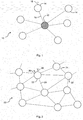
- a star topology network 10 has a single "central" node or hub 12 to which every other node 14 is connected.
- the connection may in general be via wired or wireless links 16.
- the nodes 14 may in general be any device, including for example computers (whether desktop or laptops or tablets, etc.), controllers, sensors, etc., etc.
- each node 14 in this example has an antenna 18 for wireless transmissions to and from the central hub 12, as well as a processor, data storage, a wireless transceiver, etc. (not shown) as necessary.
- a mesh topology network 20 there is no "central" node. Instead, the nodes 22 operate in a point-to-point or peer-to-peer manner. Each node 22 can send and receive its own data. Also, commonly in a mesh network 20, each node 22 also relays data received from one node 22 (a source node) that is intended ultimately for another node 22 (a sink node) to another node. The data sent from a source node 22 to a sink node 22 is therefore typically transferred via other, intermediate nodes in a multi-hop manner.
- Mesh networks may also be referred to as multi-hop networks or heterogeneous networks or the like.
- the connections between nodes 22 may in general be via wired or wireless links 24.
- the nodes 22 may in general be any device, including for example computers (whether desktop or laptops or tablets, etc.), controllers, sensors, etc., etc. As illustrated schematically in Figure 2 for one node 22, each node 22 in this example has an antenna 26 for wireless transmissions to and from other nodes 22, as well as a processor, data storage, a wireless transceiver, etc. (not shown) as necessary. Also, in this example, at least some of nodes 22 may be sensors as indicated schematically by a sensing devices 28 for one of the nodes 22 in Figure 2 .
- the sensor nodes 22 may in general be any type of sensor, including for example sensors for temperature, humidity, pressure, light levels, pollution levels, etc., etc.
- Mesh networks have a number of advantages over star networks, particularly in certain applications. For example, even if one node fails there is always an alternative present to enable data to be routed to other nodes. Also, expansion of the network by adding nodes or making other changes to the network or existing nodes can usually be carried out without disrupting other nodes. In contrast, in a star network, if for example the central hub fails, then the whole network effectively fails. Moreover, the processing and data storage requirements for the central hub are high. In addition, adding nodes has to be carried out with care, typically requiring changes at the central hub. Finally, for wireless networks, a star network often requires high power transmitters as the nodes may be a relatively large distance from the central hub. On the other hand, in a wireless mesh network, in principle a node need only communicate with one other node, which may be closely located, such that only low power transmissions are required.
- a disadvantage of conventional mesh networks over star networks is that the power requirements for the individual nodes in the star network are much more predictable and consistent than in the case of nodes in a mesh network. This is because in a star network any particular node only sends its own data to the central hub, and it is often predictable as to how much data will be sent and when it will be sent. In contrast, in a mesh network, a particular node again will have its own data to send, but also has to relay data from other nodes and it can be very difficult to predict with any accuracy when and how much data any particular node has to relay for other nodes. This is a particular problem in the case of the nodes being battery-powered as it can be difficult to predict with any accuracy how long the battery will last before discharging.
- an IoT device is a device that has an addressable interface (e.g. an Internet protocol (IP) address, a Bluetooth identifier (ID), a near-field communication (NFC) ID, etc.) and can transmit information to one or more other devices over a wired or wireless connection.
- IoT devices may in general include or be incorporated in for example refrigerators, ovens, microwaves, freezers, dishwashers, clothes washing machines, clothes dryers, furnaces, air conditioners, thermostats, televisions and other consumer electronic devices, light fixtures, vacuum cleaners, sprinklers, electricity meters, gas meters, etc.
- IoT devices may be deployed in locations or situations where there is no mains powers supply or the IoT device may not suitable for a mains power supply, including in for example the case that the IoT device is a sensor for temperature, humidity, pressure, light levels, pollution levels, etc.
- this is overcome in a wireless multi-hop network, such as a mesh network, by having a threshold relating to the data that is transmitted by the nodes, or at least some of the nodes. If the threshold has not been reached, then the node transmits data that has been received from one node and that is intended for another node to another node (i.e. the node will relay data received from one node and intended for another node). If the threshold has been reached, then the node does not transmit data that has been received from one node and that is intended for another node to another node (i.e. the node will not relay data received from one node and intended for another node). This makes the power consumption requirements of the node much more predictable.
- the power consumption requirements of the node may be controlled by adjusting the threshold, optionally in real-time.
- the threshold may be reduced in response to detection of a low charge level of a battery which is powering the node.
- the node transmits its own data that is intended for another node to another node regardless of whether or not the threshold has been reached.
- the threshold may be for example an amount of data that is transmitted by the node and/or an amount of power used for transmitting the data by the node.
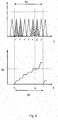
- FIGS 3 and 4 show a portion of a mesh network like the mesh network 20 shown in Figure 2 .
- Three nodes 22A, 22B, 22C are shown, it being understood that there will typically be more nodes and typically many more nodes than this. There may be for example tens or hundreds or thousands or more such nodes 22 in the mesh network 20. At least some and optionally all or substantially all of the nodes 22 are arranged and configured to behave as described herein.
- the network 20 may be for example a Low-Power Wide-Area Network (LPWAN) and at least some of the nodes 22 may be for example battery-powered sensors or other battery-powered devices.
- LPWAN Low-Power Wide-Area Network
- one node 22A needs to pass data to another node 22C.
- this is carried out by the first node 22A wirelessly transmitting 30A the data to a neighbouring "intermediate" node 22B.
- the data may be data generated or obtained by the first node 22A, for example as a result of measurements of certain parameters, such that in this sense the first node 22A is a source node for the data.
- the data may be data that has been received from another node and which this node 22A is relaying.
- the threshold relating to the data that is transmitted by the neighbouring node 22B has not been reached. Accordingly, the neighbouring node 22B transmits and therefore relays 30AR the data received from the first node 22A onto a neighbouring node 22C.
- the node 22C is the sink or intended destination of the data from the first node 22A.
- the node 22C may relay the data onto another node.
- the intermediate node 22B may also transmit 30B its own data to the neighbouring node 22C (either for the neighbouring node 22C to act as a destination or sink for that own data or for the neighbouring node 22C to relay that data onto another node).
- the threshold relating to the data that is transmitted by the neighbouring node 22B has been reached. Accordingly, the neighbouring node 22B does not transmit or relay the data received from the first node 22A. Nevertheless, as indicated, in this example the intermediate node 22B may transmit 30B its own data onto a neighbouring node 22C (again either for the neighbouring node 22C to act as a destination or sink for that own data or for the neighbouring node 22C to relay that data onto another node).
- the threshold level will typically be stored locally by the nodes 22.
- the threshold may be the same for all nodes 22 or may be different for different nodes 22.
- the threshold may be fixed.
- the threshold may be adjusted, optionally in real-time.
- the threshold may for example be adjusted for all nodes 22 and/or may for example be adjusted autonomously by each node 22, depending on for example local conditions.
- the threshold relating to the data that may be transmitted by a particular node 22 may be reduced in response to detection of a low charge level of a battery which is powering the node 22.
- At least some of the nodes 22 may be arranged such that the threshold is reset after a predetermined period of time. This may be recurrent, i.e. the threshold is reset at periodic intervals, effectively giving rise to a time frame structure.
- This is indicated schematically for a node 22 in Figure 5 .
- the upper graph of Figure 5 illustrates transmission of data from the node 22. Data that the node 22 has received from other nodes and which the node 22 is to relay onto other nodes is indicated by triangles filled with dashed lines. Data that is the node's 22 own data (for example, relating to sensor readings or the like obtained by the node 22) and which is to be transmitted to another node is indicated by plain triangles.
- the lower graph of Figure 5 illustrates the total amount of data that is transmitted by the node 22.
- the threshold for the amount of data that can be transmitted during a time period 50 is indicated at 52 in the lower graph. It may be noted that whilst the triangles in the upper graph of Figure 5 are described here as relating to the amount of data that is transmitted (e.g. measured in bytes say) and the curve in the lower graph indicates the total amount of data that is transmitted over a time period, the triangles may alternatively represent the power used by the node for the transmissions (e.g. measured in Watts) and the curve in the lower graph indicates the total amount of power that is used for transmitting the data over a time period.
- the threshold for the node 22 has just been reset. Accordingly, the node 22 is able to transmit data that has been received from other nodes as well as its own data, as indicated by a tick or ⁇ in the upper graph of Figure 5 . As indicated in the lower graph of Figure 5 , this means that the total amount of data transmitted by the node 22, or equivalently the total amount of power used for the transmissions, increases over time.
- the threshold 52 has been reached. Accordingly, following that, the node 22 does not transmit data that has been received from other nodes. This is indicated by a cross or X in the upper graph of Figure 5 .
- the node 22 is still able to transmit its own data, again indicated by a tick or ⁇ in the upper graph of Figure 5 . Then, at the end of the time period 50, the threshold is effectively reset and the node 22 is again able to transmit its own data and relay data for other nodes, at least until the threshold is reached again. As mentioned, the threshold may be reset periodically.
- the node 22 may nevertheless retain that data received from the one node. Then, once the threshold has been reset at the end of that time period 50, the node 22 may transmit its own data and the data that has been received from the one node and that is intended for another node during the next or some subsequent time period.
- the two sets of data may be sent in one transmission, which may save power, or the data may be sent in separate transmissions.
- the first node 22 may transmit a message or notification to the second node that the data will not be relayed or further transmitted. This enables the second node to transmit the data to another node with the intention that that other node will relay the data.
- nodes in wireless networks to carry out measurements of wireless links to other nodes in the network to test the quality of the links.
- Factors that may be measured include for example delay, received signal strength, signal-to-noise ratio (SNR) or signal-to-interference-plus-noise ratio (SINR), packet delivery ratio, bit error rate and throughput.
- the measurements are carried out during so-called measurement periods.
- the nodes 22, or at least some of the nodes 22, in the network 20 may be arranged such that the measurements are carried out during measurement periods which are synchronised across the nodes 22. This means that, during the measurement periods, less data is being sent by the nodes 22, which can help keep down the power requirements.
- processor or processing system or circuitry referred to herein may in practice be provided by a single chip or integrated circuit or plural chips or integrated circuits, optionally provided as a chipset, an application-specific integrated circuit (ASIC), field-programmable gate array (FPGA), digital signal processor (DSP), graphics processing units (GPUs), etc.
- the chip or chips may comprise circuitry (as well as possibly firmware) for embodying at least one or more of a data processor or processors and a digital signal processor or processors, which are configurable so as to operate in accordance with the exemplary embodiments.
- the exemplary embodiments may be implemented at least in part by computer software stored in (non-transitory) memory and executable by the processor, or by hardware, or by a combination of tangibly stored software and hardware (and tangibly stored firmware).
Landscapes
- Engineering & Computer Science (AREA)
- Computer Networks & Wireless Communication (AREA)
- Signal Processing (AREA)
- Mobile Radio Communication Systems (AREA)
Abstract
Description
- The present disclosure relates to a network of nodes and a method of operating a network of nodes, wherein the network is a wireless multi-hop network.
- Various different topologies and detailed arrangements for wireless networks of nodes are known. Examples include so-called "star" networks and "mesh" networks.
- According to a first aspect disclosed herein, there is provided a network of nodes, wherein the network is a wireless multi-hop network in which data is wirelessly transmitted between nodes and data is capable of being passed from a source node to a sink node in a multi-hop manner via one or more intermediate nodes,
at least some of the nodes being constructed and arranged such that: - a node has a threshold relating to the data that is transmitted by the node, wherein:
- if the threshold has not been reached, then the node transmits data that has been received from one node and that is intended for another node to another node, and
- if the threshold has been reached, then the node does not transmit data that has been received from one node and that is intended for another node to another node.
- In an example, said at least some of the nodes are arranged such that:
- the node transmits its own data that is intended for another node to another node regardless of whether or not the threshold has been reached.
- In an example, said at least some of the nodes are arranged such that:
- the threshold is reset after a predetermined period of time.
- In an example, said at least some of the nodes are arranged such that:
- if the threshold has been reached during a first predetermined period of time, then the node does not transmit data that has been received from one node and that is intended for another node to another node during the first predetermined period of time, and the node transmits its own data and the data that has been received from one node and that is intended for another node during a subsequent predetermined period of time.
- In an example, said at least some of the nodes are arranged such that:
- if the threshold has been reached, then the node informs a node from which data that is intended for another node has been received that the data will not be transmitted to another node.
- In an example, at least some of the nodes are arranged such that if a first node is informed by a second node that data intended for another node will not be transmitted by the second node to another node, then the first node transmits the data to another node.
- In an example, at least some of the nodes are arranged such that the nodes carry out measurements of wireless links to other nodes, wherein the measurements are carried out during measurement periods which are synchronised across the nodes.
- In an example, said at least some of the nodes are battery-powered.
- In an example, the threshold is an amount of data that is transmitted by the node.
- In an example, the threshold is an amount of power used for transmitting the data by the node.
- According to a second aspect disclosed herein, there is provided a method of operating a network of nodes, wherein the network is a wireless multi-hop network in which data is wirelessly transmitted between nodes and data is capable of being passed from a source node to a sink node in a multi-hop manner via one or more intermediate nodes, at least some of the nodes having a threshold relating to the data that is transmitted by the node, the method comprising for at least one of said nodes:
- if the threshold has not been reached, then the node transmits data that has been received from one node and that is intended for another node to another node, and
- if the threshold has been reached, then the node does not transmit data that has been received from one node and that is intended for another node to another node.
- To assist understanding of the present disclosure and to show how embodiments may be put into effect, reference is made by way of example to the accompanying drawings in which:
-
Figure 1 shows schematically a star network; -
Figure 2 shows schematically a mesh network; -
Figure 3 shows schematically transmission and relaying of data by a node; -
Figure 4 shows schematically transmission of data by a node; and -
Figure 5 shows graphs indicating transmission of data and total amount of data transmitted and/or power used for the transmission. - As mentioned, various different topologies and detailed arrangements for wireless networks of nodes are known. Examples include so-called "star" networks and "mesh" networks.
- Referring to
Figure 1 , in its simplest form, astar topology network 10 has a single "central" node orhub 12 to which everyother node 14 is connected. The connection may in general be via wired orwireless links 16. Typically theother nodes 14 are not connected to each other. Thenodes 14 may in general be any device, including for example computers (whether desktop or laptops or tablets, etc.), controllers, sensors, etc., etc. As illustrated schematically inFigure 1 for one node, eachnode 14 in this example has anantenna 18 for wireless transmissions to and from thecentral hub 12, as well as a processor, data storage, a wireless transceiver, etc. (not shown) as necessary. - Referring to
Figure 2 , in contrast, in amesh topology network 20, there is no "central" node. Instead, thenodes 22 operate in a point-to-point or peer-to-peer manner. Eachnode 22 can send and receive its own data. Also, commonly in amesh network 20, eachnode 22 also relays data received from one node 22 (a source node) that is intended ultimately for another node 22 (a sink node) to another node. The data sent from asource node 22 to asink node 22 is therefore typically transferred via other, intermediate nodes in a multi-hop manner. Mesh networks may also be referred to as multi-hop networks or heterogeneous networks or the like. The connections betweennodes 22 may in general be via wired orwireless links 24. Thenodes 22 may in general be any device, including for example computers (whether desktop or laptops or tablets, etc.), controllers, sensors, etc., etc. As illustrated schematically inFigure 2 for onenode 22, eachnode 22 in this example has anantenna 26 for wireless transmissions to and fromother nodes 22, as well as a processor, data storage, a wireless transceiver, etc. (not shown) as necessary. Also, in this example, at least some ofnodes 22 may be sensors as indicated schematically by asensing devices 28 for one of thenodes 22 inFigure 2 . Thesensor nodes 22 may in general be any type of sensor, including for example sensors for temperature, humidity, pressure, light levels, pollution levels, etc., etc. - Mesh networks have a number of advantages over star networks, particularly in certain applications. For example, even if one node fails there is always an alternative present to enable data to be routed to other nodes. Also, expansion of the network by adding nodes or making other changes to the network or existing nodes can usually be carried out without disrupting other nodes. In contrast, in a star network, if for example the central hub fails, then the whole network effectively fails. Moreover, the processing and data storage requirements for the central hub are high. In addition, adding nodes has to be carried out with care, typically requiring changes at the central hub. Finally, for wireless networks, a star network often requires high power transmitters as the nodes may be a relatively large distance from the central hub. On the other hand, in a wireless mesh network, in principle a node need only communicate with one other node, which may be closely located, such that only low power transmissions are required.
- Nevertheless, a disadvantage of conventional mesh networks over star networks is that the power requirements for the individual nodes in the star network are much more predictable and consistent than in the case of nodes in a mesh network. This is because in a star network any particular node only sends its own data to the central hub, and it is often predictable as to how much data will be sent and when it will be sent. In contrast, in a mesh network, a particular node again will have its own data to send, but also has to relay data from other nodes and it can be very difficult to predict with any accuracy when and how much data any particular node has to relay for other nodes. This is a particular problem in the case of the nodes being battery-powered as it can be difficult to predict with any accuracy how long the battery will last before discharging. Battery-powered sensors and other battery-powered devices connected in a mesh network are of increasing commercial importance, including in for example "Internet of Things" or IoT devices. In general, as used herein, an IoT device is a device that has an addressable interface (e.g. an Internet protocol (IP) address, a Bluetooth identifier (ID), a near-field communication (NFC) ID, etc.) and can transmit information to one or more other devices over a wired or wireless connection. IoT devices may in general include or be incorporated in for example refrigerators, ovens, microwaves, freezers, dishwashers, clothes washing machines, clothes dryers, furnaces, air conditioners, thermostats, televisions and other consumer electronic devices, light fixtures, vacuum cleaners, sprinklers, electricity meters, gas meters, etc. IoT devices may be deployed in locations or situations where there is no mains powers supply or the IoT device may not suitable for a mains power supply, including in for example the case that the IoT device is a sensor for temperature, humidity, pressure, light levels, pollution levels, etc.
- In accordance with the present disclosure, this is overcome in a wireless multi-hop network, such as a mesh network, by having a threshold relating to the data that is transmitted by the nodes, or at least some of the nodes. If the threshold has not been reached, then the node transmits data that has been received from one node and that is intended for another node to another node (i.e. the node will relay data received from one node and intended for another node). If the threshold has been reached, then the node does not transmit data that has been received from one node and that is intended for another node to another node (i.e. the node will not relay data received from one node and intended for another node). This makes the power consumption requirements of the node much more predictable. Indeed, the power consumption requirements of the node may be controlled by adjusting the threshold, optionally in real-time. For example, the threshold may be reduced in response to detection of a low charge level of a battery which is powering the node. In some examples, the node transmits its own data that is intended for another node to another node regardless of whether or not the threshold has been reached. The threshold may be for example an amount of data that is transmitted by the node and/or an amount of power used for transmitting the data by the node.
- This is illustrated schematically in
Figures 3 and 4 , which show a portion of a mesh network like themesh network 20 shown inFigure 2 . Threenodes such nodes 22 in themesh network 20. At least some and optionally all or substantially all of thenodes 22 are arranged and configured to behave as described herein. (It will be appreciated that there may benodes 22 in themesh network 22 that do not require this functionality, and that, depending on the network and the nature of thenodes 22, this may only be a small proportion or a large proportion.) Thenetwork 20 may be for example a Low-Power Wide-Area Network (LPWAN) and at least some of thenodes 22 may be for example battery-powered sensors or other battery-powered devices. - In
Figures 3 and 4 , onenode 22A needs to pass data to anothernode 22C. In this example, this is carried out by thefirst node 22A wirelessly transmitting 30A the data to a neighbouring "intermediate"node 22B. The data may be data generated or obtained by thefirst node 22A, for example as a result of measurements of certain parameters, such that in this sense thefirst node 22A is a source node for the data. Alternatively or additionally, the data may be data that has been received from another node and which thisnode 22A is relaying. - In
Figure 3 , the threshold relating to the data that is transmitted by the neighbouringnode 22B has not been reached. Accordingly, the neighbouringnode 22B transmits and therefore relays 30AR the data received from thefirst node 22A onto a neighbouringnode 22C. In this case, thenode 22C is the sink or intended destination of the data from thefirst node 22A. In other examples, thenode 22C may relay the data onto another node. Theintermediate node 22B may also transmit 30B its own data to the neighbouringnode 22C (either for the neighbouringnode 22C to act as a destination or sink for that own data or for the neighbouringnode 22C to relay that data onto another node). - On the other hand, in
Figure 4 the threshold relating to the data that is transmitted by the neighbouringnode 22B has been reached. Accordingly, the neighbouringnode 22B does not transmit or relay the data received from thefirst node 22A. Nevertheless, as indicated, in this example theintermediate node 22B may transmit 30B its own data onto a neighbouringnode 22C (again either for the neighbouringnode 22C to act as a destination or sink for that own data or for the neighbouringnode 22C to relay that data onto another node). - The threshold level will typically be stored locally by the
nodes 22. The threshold may be the same for allnodes 22 or may be different fordifferent nodes 22. The threshold may be fixed. Alternatively, as mentioned, the threshold may be adjusted, optionally in real-time. The threshold may for example be adjusted for allnodes 22 and/or may for example be adjusted autonomously by eachnode 22, depending on for example local conditions. For example, the threshold relating to the data that may be transmitted by aparticular node 22 may be reduced in response to detection of a low charge level of a battery which is powering thenode 22. - At least some of the
nodes 22 may be arranged such that the threshold is reset after a predetermined period of time. This may be recurrent, i.e. the threshold is reset at periodic intervals, effectively giving rise to a time frame structure. This is indicated schematically for anode 22 inFigure 5 . The upper graph ofFigure 5 illustrates transmission of data from thenode 22. Data that thenode 22 has received from other nodes and which thenode 22 is to relay onto other nodes is indicated by triangles filled with dashed lines. Data that is the node's 22 own data (for example, relating to sensor readings or the like obtained by the node 22) and which is to be transmitted to another node is indicated by plain triangles. The lower graph ofFigure 5 illustrates the total amount of data that is transmitted by thenode 22. The threshold for the amount of data that can be transmitted during atime period 50 is indicated at 52 in the lower graph. It may be noted that whilst the triangles in the upper graph ofFigure 5 are described here as relating to the amount of data that is transmitted (e.g. measured in bytes say) and the curve in the lower graph indicates the total amount of data that is transmitted over a time period, the triangles may alternatively represent the power used by the node for the transmissions (e.g. measured in Watts) and the curve in the lower graph indicates the total amount of power that is used for transmitting the data over a time period. - Initially, at time to, the threshold for the
node 22 has just been reset. Accordingly, thenode 22 is able to transmit data that has been received from other nodes as well as its own data, as indicated by a tick or ✔ in the upper graph ofFigure 5 . As indicated in the lower graph ofFigure 5 , this means that the total amount of data transmitted by thenode 22, or equivalently the total amount of power used for the transmissions, increases over time. At time tT, thethreshold 52 has been reached. Accordingly, following that, thenode 22 does not transmit data that has been received from other nodes. This is indicated by a cross or X in the upper graph ofFigure 5 . Nevertheless, in this example, thenode 22 is still able to transmit its own data, again indicated by a tick or ✔ in the upper graph ofFigure 5 . Then, at the end of thetime period 50, the threshold is effectively reset and thenode 22 is again able to transmit its own data and relay data for other nodes, at least until the threshold is reached again. As mentioned, the threshold may be reset periodically. - In an example in the case that the
threshold 52 for anode 22 has been reached during afirst time period 50 such that thenode 22 does not transmit data that has been received from one node and that is intended for another node to another node during thefirst time period 50, thenode 22 may nevertheless retain that data received from the one node. Then, once the threshold has been reset at the end of thattime period 50, thenode 22 may transmit its own data and the data that has been received from the one node and that is intended for another node during the next or some subsequent time period. The two sets of data may be sent in one transmission, which may save power, or the data may be sent in separate transmissions. - In the case that the
threshold 52 for thenode 22 has been reached and thenode 22 receives data from a second node which it is intended should be relayed on to a third node, then thefirst node 22 may transmit a message or notification to the second node that the data will not be relayed or further transmitted. This enables the second node to transmit the data to another node with the intention that that other node will relay the data. - It is known for nodes in wireless networks to carry out measurements of wireless links to other nodes in the network to test the quality of the links. Factors that may be measured include for example delay, received signal strength, signal-to-noise ratio (SNR) or signal-to-interference-plus-noise ratio (SINR), packet delivery ratio, bit error rate and throughput. The measurements are carried out during so-called measurement periods. In another example of the present disclosure, the
nodes 22, or at least some of thenodes 22, in thenetwork 20 may be arranged such that the measurements are carried out during measurement periods which are synchronised across thenodes 22. This means that, during the measurement periods, less data is being sent by thenodes 22, which can help keep down the power requirements. - It will be understood that the processor or processing system or circuitry referred to herein may in practice be provided by a single chip or integrated circuit or plural chips or integrated circuits, optionally provided as a chipset, an application-specific integrated circuit (ASIC), field-programmable gate array (FPGA), digital signal processor (DSP), graphics processing units (GPUs), etc. The chip or chips may comprise circuitry (as well as possibly firmware) for embodying at least one or more of a data processor or processors and a digital signal processor or processors, which are configurable so as to operate in accordance with the exemplary embodiments. In this regard, the exemplary embodiments may be implemented at least in part by computer software stored in (non-transitory) memory and executable by the processor, or by hardware, or by a combination of tangibly stored software and hardware (and tangibly stored firmware).
- Reference is made herein to data storage for storing data. This may be provided by a single device or by plural devices. Suitable devices include for example a hard disk and non-volatile semiconductor memory.
- The examples described herein are to be understood as illustrative examples of embodiments of the invention. Further embodiments and examples are envisaged. Any feature described in relation to any one example or embodiment may be used alone or in combination with other features. In addition, any feature described in relation to any one example or embodiment may also be used in combination with one or more features of any other of the examples or embodiments, or any combination of any other of the examples or embodiments. Furthermore, equivalents and modifications not described herein may also be employed within the scope of the invention, which is defined in the claims.
Claims (15)
- A network of nodes, wherein the network is a wireless multi-hop network in which data is wirelessly transmitted between nodes and data is capable of being passed from a source node to a sink node in a multi-hop manner via one or more intermediate nodes,
at least some of the nodes being constructed and arranged such that:a node has a threshold relating to the data that is transmitted by the node, wherein:if the threshold has not been reached, then the node transmits data that has been received from one node and that is intended for another node to another node, andif the threshold has been reached, then the node does not transmit data that has been received from one node and that is intended for another node to another node. - A network of nodes according to claim 1, wherein said at least some of the nodes are arranged such that:the node transmits its own data that is intended for another node to another node regardless of whether or not the threshold has been reached.
- A network of nodes according to claim 1 or claim 2, wherein said at least some of the nodes are arranged such that:the threshold is reset after a predetermined period of time.
- A network of nodes according to claim 3, wherein said at least some of the nodes are arranged such that:if the threshold has been reached during a first predetermined period of time, then the node does not transmit data that has been received from one node and that is intended for another node to another node during the first predetermined period of time, and the node transmits its own data and the data that has been received from one node and that is intended for another node during a subsequent predetermined period of time.
- A network of nodes according to any of claims 1 to 4, wherein said at least some of the nodes are arranged such that:if the threshold has been reached, then the node informs a node from which data that is intended for another node has been received that the data will not be transmitted to another node.
- A network of nodes according to claim 5, wherein at least some of the nodes are arranged such that if a first node is informed by a second node that data intended for another node will not be transmitted by the second node to another node, then the first node transmits the data to another node.
- A network of nodes according to any of claims 1 to 6, wherein at least some of the nodes are arranged such that the nodes carry out measurements of wireless links to other nodes, wherein the measurements are carried out during measurement periods which are synchronised across the nodes.
- A network of nodes according to any of claims 1 to 7, wherein said at least some of the nodes are battery-powered.
- A network of nodes according to any of claims 1 to 8, wherein the threshold is an amount of data that is transmitted by the node.
- A network of nodes according to any of claims 1 to 9, wherein the threshold is an amount of power used for transmitting the data by the node.
- A method of operating a network of nodes, wherein the network is a wireless multi-hop network in which data is wirelessly transmitted between nodes and data is capable of being passed from a source node to a sink node in a multi-hop manner via one or more intermediate nodes, at least some of the nodes having a threshold relating to data that is transmitted by the node, the method comprising for at least one of said nodes:if the threshold has not been reached, then the node transmits data that has been received from one node and that is intended for another node to another node, andif the threshold has been reached, then the node does not transmit data that has been received from one node and that is intended for another node to another node.
- A method according to claim 11, wherein the node transmits its own data that is intended for another node to another node regardless of whether or not the threshold has been reached.
- A method according to claim 11 or claim 12, comprising resetting the threshold after a predetermined period of time.
- A method according to claim 13, comprising:if the threshold has been reached during a first predetermined period of time, the node does not transmit data that has been received from one node and that is intended for another node to another node during the first predetermined period of time, and the node transmits its own data and the data that has been received from one node and that is intended for another node during a subsequent predetermined period of time.
- A method according to any of claims 11 to 14, comprising:if the threshold has been reached, the node informing a node from which data that is intended for another node has been received that the data will not be transmitted to another node.
Priority Applications (2)
| Application Number | Priority Date | Filing Date | Title |
|---|---|---|---|
| EP17176441.8A EP3416420B1 (en) | 2017-06-16 | 2017-06-16 | Network of nodes and method of operating a network of nodes |
| TR2017/09439A TR201709439A2 (en) | 2017-06-16 | 2017-06-23 | THE NODE NETWORK AND THE OPERATION METHOD OF A NODE NETWORK |
Applications Claiming Priority (1)
| Application Number | Priority Date | Filing Date | Title |
|---|---|---|---|
| EP17176441.8A EP3416420B1 (en) | 2017-06-16 | 2017-06-16 | Network of nodes and method of operating a network of nodes |
Publications (2)
| Publication Number | Publication Date |
|---|---|
| EP3416420A1 true EP3416420A1 (en) | 2018-12-19 |
| EP3416420B1 EP3416420B1 (en) | 2021-04-28 |
Family
ID=59077907
Family Applications (1)
| Application Number | Title | Priority Date | Filing Date |
|---|---|---|---|
| EP17176441.8A Active EP3416420B1 (en) | 2017-06-16 | 2017-06-16 | Network of nodes and method of operating a network of nodes |
Country Status (2)
| Country | Link |
|---|---|
| EP (1) | EP3416420B1 (en) |
| TR (1) | TR201709439A2 (en) |
Cited By (1)
| Publication number | Priority date | Publication date | Assignee | Title |
|---|---|---|---|---|
| EP4464948A4 (en) * | 2022-01-11 | 2025-04-16 | Daikin Industries, Ltd. | RELAY DEVICE, AIR CONDITIONING SYSTEM AND COMMUNICATION METHOD |
Citations (2)
| Publication number | Priority date | Publication date | Assignee | Title |
|---|---|---|---|---|
| WO2012034607A1 (en) * | 2010-09-17 | 2012-03-22 | Telefonica, S.A. | A multi-hop and multi-path store and forward system, method and product for bulk transfers |
| US20130121176A1 (en) * | 2011-11-16 | 2013-05-16 | Cisco Technology, Inc. | Communication protocol for energy-harvesting devices |
-
2017
- 2017-06-16 EP EP17176441.8A patent/EP3416420B1/en active Active
- 2017-06-23 TR TR2017/09439A patent/TR201709439A2/en unknown
Patent Citations (2)
| Publication number | Priority date | Publication date | Assignee | Title |
|---|---|---|---|---|
| WO2012034607A1 (en) * | 2010-09-17 | 2012-03-22 | Telefonica, S.A. | A multi-hop and multi-path store and forward system, method and product for bulk transfers |
| US20130121176A1 (en) * | 2011-11-16 | 2013-05-16 | Cisco Technology, Inc. | Communication protocol for energy-harvesting devices |
Cited By (1)
| Publication number | Priority date | Publication date | Assignee | Title |
|---|---|---|---|---|
| EP4464948A4 (en) * | 2022-01-11 | 2025-04-16 | Daikin Industries, Ltd. | RELAY DEVICE, AIR CONDITIONING SYSTEM AND COMMUNICATION METHOD |
Also Published As
| Publication number | Publication date |
|---|---|
| EP3416420B1 (en) | 2021-04-28 |
| TR201709439A2 (en) | 2019-01-21 |
Similar Documents
| Publication | Publication Date | Title |
|---|---|---|
| US9842202B2 (en) | Device proximity | |
| CN107005443B (en) | Method for relaying messages, residential gateway, storage device | |
| US9565620B2 (en) | Dynamic routing in a mesh network | |
| EP2443901B1 (en) | Apparatuses and methods for ambient noise adaptation in wireless sensor networks | |
| JP5953371B2 (en) | Wireless sensor network | |
| JP5939262B2 (en) | Transmission control method, node, and transmission control program | |
| US20180167864A1 (en) | Multi-hop networking protocol for wide-area energy harvesting sensor network deployments | |
| US10439749B2 (en) | Wireless communication device and wireless communication system | |
| CN108029155B (en) | mesh network node | |
| JPWO2016147267A1 (en) | Control device, control program, and sensor node | |
| JP6554798B2 (en) | Wireless communication system | |
| JP6007743B2 (en) | Multihop communication terminal, multihop communication system, and multihop communication method | |
| US10178629B2 (en) | Communications node, system, communications method, and computer product | |
| EP3416420B1 (en) | Network of nodes and method of operating a network of nodes | |
| US10979865B2 (en) | Handling of devices based on group membership | |
| CN106060771B (en) | Method and device for dynamic adjustment of transmission power of Zigbee transmission equipment | |
| JP5885242B2 (en) | Sensor node, sensor node control method, and sensor node control program | |
| US20160205568A1 (en) | Visual signal strength indication for wireless devices | |
| JP5605096B2 (en) | Node device, time synchronization system, and time synchronization method | |
| US8964592B2 (en) | Wireless terminal device, wireless communication system and control method for wireless terminal device | |
| US20160309541A1 (en) | Wireless communication system, wireless communication apparatus, and wireless communication method | |
| CN103826262B (en) | Wireless communication system, wireless communication method, transmitting terminal, and receiving terminal | |
| JP2018137535A (en) | Apparatus control system, communication method, radio terminal, and controller | |
| McNally et al. | Location Discovery in SpeckNets Using Relative Direction Information | |
| HK1168489B (en) | Apparatuses and methods for ambient noise adaptation in wireless sensor networks |
Legal Events
| Date | Code | Title | Description |
|---|---|---|---|
| PUAI | Public reference made under article 153(3) epc to a published international application that has entered the european phase |
Free format text: ORIGINAL CODE: 0009012 |
|
| STAA | Information on the status of an ep patent application or granted ep patent |
Free format text: STATUS: THE APPLICATION HAS BEEN PUBLISHED |
|
| AK | Designated contracting states |
Kind code of ref document: A1 Designated state(s): AL AT BE BG CH CY CZ DE DK EE ES FI FR GB GR HR HU IE IS IT LI LT LU LV MC MK MT NL NO PL PT RO RS SE SI SK SM TR |
|
| AX | Request for extension of the european patent |
Extension state: BA ME |
|
| STAA | Information on the status of an ep patent application or granted ep patent |
Free format text: STATUS: REQUEST FOR EXAMINATION WAS MADE |
|
| 17P | Request for examination filed |
Effective date: 20190619 |
|
| RBV | Designated contracting states (corrected) |
Designated state(s): AL AT BE BG CH CY CZ DE DK EE ES FI FR GB GR HR HU IE IS IT LI LT LU LV MC MK MT NL NO PL PT RO RS SE SI SK SM TR |
|
| STAA | Information on the status of an ep patent application or granted ep patent |
Free format text: STATUS: EXAMINATION IS IN PROGRESS |
|
| 17Q | First examination report despatched |
Effective date: 20191219 |
|
| GRAP | Despatch of communication of intention to grant a patent |
Free format text: ORIGINAL CODE: EPIDOSNIGR1 |
|
| STAA | Information on the status of an ep patent application or granted ep patent |
Free format text: STATUS: GRANT OF PATENT IS INTENDED |
|
| RIC1 | Information provided on ipc code assigned before grant |
Ipc: H04W 28/02 20090101AFI20201023BHEP Ipc: H04W 84/18 20090101ALN20201023BHEP Ipc: H04W 88/04 20090101ALN20201023BHEP Ipc: H04W 40/22 20090101ALI20201023BHEP Ipc: H04W 40/10 20090101ALI20201023BHEP |
|
| RIC1 | Information provided on ipc code assigned before grant |
Ipc: H04W 28/02 20090101AFI20201106BHEP Ipc: H04W 88/04 20090101ALN20201106BHEP Ipc: H04W 40/10 20090101ALI20201106BHEP Ipc: H04W 84/18 20090101ALN20201106BHEP Ipc: H04W 40/22 20090101ALI20201106BHEP |
|
| INTG | Intention to grant announced |
Effective date: 20201126 |
|
| GRAS | Grant fee paid |
Free format text: ORIGINAL CODE: EPIDOSNIGR3 |
|
| GRAA | (expected) grant |
Free format text: ORIGINAL CODE: 0009210 |
|
| STAA | Information on the status of an ep patent application or granted ep patent |
Free format text: STATUS: THE PATENT HAS BEEN GRANTED |
|
| AK | Designated contracting states |
Kind code of ref document: B1 Designated state(s): AL AT BE BG CH CY CZ DE DK EE ES FI FR GB GR HR HU IE IS IT LI LT LU LV MC MK MT NL NO PL PT RO RS SE SI SK SM TR |
|
| REG | Reference to a national code |
Ref country code: GB Ref legal event code: FG4D |
|
| REG | Reference to a national code |
Ref country code: CH Ref legal event code: EP |
|
| REG | Reference to a national code |
Ref country code: AT Ref legal event code: REF Ref document number: 1388529 Country of ref document: AT Kind code of ref document: T Effective date: 20210515 |
|
| REG | Reference to a national code |
Ref country code: DE Ref legal event code: R096 Ref document number: 602017037456 Country of ref document: DE |
|
| REG | Reference to a national code |
Ref country code: IE Ref legal event code: FG4D |
|
| REG | Reference to a national code |
Ref country code: LT Ref legal event code: MG9D |
|
| REG | Reference to a national code |
Ref country code: AT Ref legal event code: MK05 Ref document number: 1388529 Country of ref document: AT Kind code of ref document: T Effective date: 20210428 |
|
| PG25 | Lapsed in a contracting state [announced via postgrant information from national office to epo] |
Ref country code: FI Free format text: LAPSE BECAUSE OF FAILURE TO SUBMIT A TRANSLATION OF THE DESCRIPTION OR TO PAY THE FEE WITHIN THE PRESCRIBED TIME-LIMIT Effective date: 20210428 Ref country code: LT Free format text: LAPSE BECAUSE OF FAILURE TO SUBMIT A TRANSLATION OF THE DESCRIPTION OR TO PAY THE FEE WITHIN THE PRESCRIBED TIME-LIMIT Effective date: 20210428 Ref country code: AT Free format text: LAPSE BECAUSE OF FAILURE TO SUBMIT A TRANSLATION OF THE DESCRIPTION OR TO PAY THE FEE WITHIN THE PRESCRIBED TIME-LIMIT Effective date: 20210428 Ref country code: BG Free format text: LAPSE BECAUSE OF FAILURE TO SUBMIT A TRANSLATION OF THE DESCRIPTION OR TO PAY THE FEE WITHIN THE PRESCRIBED TIME-LIMIT Effective date: 20210728 Ref country code: HR Free format text: LAPSE BECAUSE OF FAILURE TO SUBMIT A TRANSLATION OF THE DESCRIPTION OR TO PAY THE FEE WITHIN THE PRESCRIBED TIME-LIMIT Effective date: 20210428 Ref country code: NL Free format text: LAPSE BECAUSE OF FAILURE TO SUBMIT A TRANSLATION OF THE DESCRIPTION OR TO PAY THE FEE WITHIN THE PRESCRIBED TIME-LIMIT Effective date: 20210428 |
|
| PG25 | Lapsed in a contracting state [announced via postgrant information from national office to epo] |
Ref country code: PT Free format text: LAPSE BECAUSE OF FAILURE TO SUBMIT A TRANSLATION OF THE DESCRIPTION OR TO PAY THE FEE WITHIN THE PRESCRIBED TIME-LIMIT Effective date: 20210830 Ref country code: PL Free format text: LAPSE BECAUSE OF FAILURE TO SUBMIT A TRANSLATION OF THE DESCRIPTION OR TO PAY THE FEE WITHIN THE PRESCRIBED TIME-LIMIT Effective date: 20210428 Ref country code: NO Free format text: LAPSE BECAUSE OF FAILURE TO SUBMIT A TRANSLATION OF THE DESCRIPTION OR TO PAY THE FEE WITHIN THE PRESCRIBED TIME-LIMIT Effective date: 20210728 Ref country code: SE Free format text: LAPSE BECAUSE OF FAILURE TO SUBMIT A TRANSLATION OF THE DESCRIPTION OR TO PAY THE FEE WITHIN THE PRESCRIBED TIME-LIMIT Effective date: 20210428 Ref country code: RS Free format text: LAPSE BECAUSE OF FAILURE TO SUBMIT A TRANSLATION OF THE DESCRIPTION OR TO PAY THE FEE WITHIN THE PRESCRIBED TIME-LIMIT Effective date: 20210428 Ref country code: LV Free format text: LAPSE BECAUSE OF FAILURE TO SUBMIT A TRANSLATION OF THE DESCRIPTION OR TO PAY THE FEE WITHIN THE PRESCRIBED TIME-LIMIT Effective date: 20210428 Ref country code: GR Free format text: LAPSE BECAUSE OF FAILURE TO SUBMIT A TRANSLATION OF THE DESCRIPTION OR TO PAY THE FEE WITHIN THE PRESCRIBED TIME-LIMIT Effective date: 20210729 Ref country code: IS Free format text: LAPSE BECAUSE OF FAILURE TO SUBMIT A TRANSLATION OF THE DESCRIPTION OR TO PAY THE FEE WITHIN THE PRESCRIBED TIME-LIMIT Effective date: 20210828 |
|
| REG | Reference to a national code |
Ref country code: NL Ref legal event code: MP Effective date: 20210428 |
|
| PG25 | Lapsed in a contracting state [announced via postgrant information from national office to epo] |
Ref country code: RO Free format text: LAPSE BECAUSE OF FAILURE TO SUBMIT A TRANSLATION OF THE DESCRIPTION OR TO PAY THE FEE WITHIN THE PRESCRIBED TIME-LIMIT Effective date: 20210428 Ref country code: ES Free format text: LAPSE BECAUSE OF FAILURE TO SUBMIT A TRANSLATION OF THE DESCRIPTION OR TO PAY THE FEE WITHIN THE PRESCRIBED TIME-LIMIT Effective date: 20210428 Ref country code: CZ Free format text: LAPSE BECAUSE OF FAILURE TO SUBMIT A TRANSLATION OF THE DESCRIPTION OR TO PAY THE FEE WITHIN THE PRESCRIBED TIME-LIMIT Effective date: 20210428 Ref country code: DK Free format text: LAPSE BECAUSE OF FAILURE TO SUBMIT A TRANSLATION OF THE DESCRIPTION OR TO PAY THE FEE WITHIN THE PRESCRIBED TIME-LIMIT Effective date: 20210428 Ref country code: EE Free format text: LAPSE BECAUSE OF FAILURE TO SUBMIT A TRANSLATION OF THE DESCRIPTION OR TO PAY THE FEE WITHIN THE PRESCRIBED TIME-LIMIT Effective date: 20210428 Ref country code: MC Free format text: LAPSE BECAUSE OF FAILURE TO SUBMIT A TRANSLATION OF THE DESCRIPTION OR TO PAY THE FEE WITHIN THE PRESCRIBED TIME-LIMIT Effective date: 20210428 Ref country code: SK Free format text: LAPSE BECAUSE OF FAILURE TO SUBMIT A TRANSLATION OF THE DESCRIPTION OR TO PAY THE FEE WITHIN THE PRESCRIBED TIME-LIMIT Effective date: 20210428 Ref country code: SM Free format text: LAPSE BECAUSE OF FAILURE TO SUBMIT A TRANSLATION OF THE DESCRIPTION OR TO PAY THE FEE WITHIN THE PRESCRIBED TIME-LIMIT Effective date: 20210428 |
|
| REG | Reference to a national code |
Ref country code: DE Ref legal event code: R097 Ref document number: 602017037456 Country of ref document: DE Ref country code: CH Ref legal event code: PL |
|
| PLBE | No opposition filed within time limit |
Free format text: ORIGINAL CODE: 0009261 |
|
| STAA | Information on the status of an ep patent application or granted ep patent |
Free format text: STATUS: NO OPPOSITION FILED WITHIN TIME LIMIT |
|
| REG | Reference to a national code |
Ref country code: BE Ref legal event code: MM Effective date: 20210630 |
|
| PG25 | Lapsed in a contracting state [announced via postgrant information from national office to epo] |
Ref country code: LU Free format text: LAPSE BECAUSE OF NON-PAYMENT OF DUE FEES Effective date: 20210616 |
|
| 26N | No opposition filed |
Effective date: 20220131 |
|
| PG25 | Lapsed in a contracting state [announced via postgrant information from national office to epo] |
Ref country code: LI Free format text: LAPSE BECAUSE OF NON-PAYMENT OF DUE FEES Effective date: 20210630 Ref country code: IE Free format text: LAPSE BECAUSE OF NON-PAYMENT OF DUE FEES Effective date: 20210616 Ref country code: CH Free format text: LAPSE BECAUSE OF NON-PAYMENT OF DUE FEES Effective date: 20210630 |
|
| PG25 | Lapsed in a contracting state [announced via postgrant information from national office to epo] |
Ref country code: IS Free format text: LAPSE BECAUSE OF FAILURE TO SUBMIT A TRANSLATION OF THE DESCRIPTION OR TO PAY THE FEE WITHIN THE PRESCRIBED TIME-LIMIT Effective date: 20210828 Ref country code: FR Free format text: LAPSE BECAUSE OF NON-PAYMENT OF DUE FEES Effective date: 20210628 Ref country code: AL Free format text: LAPSE BECAUSE OF FAILURE TO SUBMIT A TRANSLATION OF THE DESCRIPTION OR TO PAY THE FEE WITHIN THE PRESCRIBED TIME-LIMIT Effective date: 20210428 |
|
| PG25 | Lapsed in a contracting state [announced via postgrant information from national office to epo] |
Ref country code: IT Free format text: LAPSE BECAUSE OF FAILURE TO SUBMIT A TRANSLATION OF THE DESCRIPTION OR TO PAY THE FEE WITHIN THE PRESCRIBED TIME-LIMIT Effective date: 20210428 Ref country code: BE Free format text: LAPSE BECAUSE OF NON-PAYMENT OF DUE FEES Effective date: 20210630 |
|
| PG25 | Lapsed in a contracting state [announced via postgrant information from national office to epo] |
Ref country code: CY Free format text: LAPSE BECAUSE OF FAILURE TO SUBMIT A TRANSLATION OF THE DESCRIPTION OR TO PAY THE FEE WITHIN THE PRESCRIBED TIME-LIMIT Effective date: 20210428 |
|
| PG25 | Lapsed in a contracting state [announced via postgrant information from national office to epo] |
Ref country code: HU Free format text: LAPSE BECAUSE OF FAILURE TO SUBMIT A TRANSLATION OF THE DESCRIPTION OR TO PAY THE FEE WITHIN THE PRESCRIBED TIME-LIMIT; INVALID AB INITIO Effective date: 20170616 |
|
| PG25 | Lapsed in a contracting state [announced via postgrant information from national office to epo] |
Ref country code: MK Free format text: LAPSE BECAUSE OF FAILURE TO SUBMIT A TRANSLATION OF THE DESCRIPTION OR TO PAY THE FEE WITHIN THE PRESCRIBED TIME-LIMIT Effective date: 20210428 |
|
| PG25 | Lapsed in a contracting state [announced via postgrant information from national office to epo] |
Ref country code: MT Free format text: LAPSE BECAUSE OF FAILURE TO SUBMIT A TRANSLATION OF THE DESCRIPTION OR TO PAY THE FEE WITHIN THE PRESCRIBED TIME-LIMIT Effective date: 20210428 |
|
| PGFP | Annual fee paid to national office [announced via postgrant information from national office to epo] |
Ref country code: DE Payment date: 20250618 Year of fee payment: 9 |
|
| PGFP | Annual fee paid to national office [announced via postgrant information from national office to epo] |
Ref country code: GB Payment date: 20250618 Year of fee payment: 9 |
|
| REG | Reference to a national code |
Ref country code: DE Ref legal event code: R082 Ref document number: 602017037456 Country of ref document: DE Representative=s name: WESTPHAL, MUSSGNUG & PARTNER PATENTANWAELTE MI, DE |
|
| PGFP | Annual fee paid to national office [announced via postgrant information from national office to epo] |
Ref country code: TR Payment date: 20260612 Year of fee payment: 10 |