EP3416225A1 - Electrode assembly and manufacturing method therefor - Google Patents
Electrode assembly and manufacturing method therefor Download PDFInfo
- Publication number
- EP3416225A1 EP3416225A1 EP17869470.9A EP17869470A EP3416225A1 EP 3416225 A1 EP3416225 A1 EP 3416225A1 EP 17869470 A EP17869470 A EP 17869470A EP 3416225 A1 EP3416225 A1 EP 3416225A1
- Authority
- EP
- European Patent Office
- Prior art keywords
- unit cell
- separation film
- folding
- folding part
- surround
- Prior art date
- Legal status (The legal status is an assumption and is not a legal conclusion. Google has not performed a legal analysis and makes no representation as to the accuracy of the status listed.)
- Granted
Links
Images



Classifications
-
- H—ELECTRICITY
- H01—ELECTRIC ELEMENTS
- H01M—PROCESSES OR MEANS, e.g. BATTERIES, FOR THE DIRECT CONVERSION OF CHEMICAL ENERGY INTO ELECTRICAL ENERGY
- H01M10/00—Secondary cells; Manufacture thereof
- H01M10/04—Construction or manufacture in general
- H01M10/0436—Small-sized flat cells or batteries for portable equipment
-
- H—ELECTRICITY
- H01—ELECTRIC ELEMENTS
- H01M—PROCESSES OR MEANS, e.g. BATTERIES, FOR THE DIRECT CONVERSION OF CHEMICAL ENERGY INTO ELECTRICAL ENERGY
- H01M4/00—Electrodes
- H01M4/02—Electrodes composed of, or comprising, active material
-
- H—ELECTRICITY
- H01—ELECTRIC ELEMENTS
- H01M—PROCESSES OR MEANS, e.g. BATTERIES, FOR THE DIRECT CONVERSION OF CHEMICAL ENERGY INTO ELECTRICAL ENERGY
- H01M10/00—Secondary cells; Manufacture thereof
- H01M10/04—Construction or manufacture in general
-
- H—ELECTRICITY
- H01—ELECTRIC ELEMENTS
- H01M—PROCESSES OR MEANS, e.g. BATTERIES, FOR THE DIRECT CONVERSION OF CHEMICAL ENERGY INTO ELECTRICAL ENERGY
- H01M10/00—Secondary cells; Manufacture thereof
- H01M10/04—Construction or manufacture in general
- H01M10/0459—Cells or batteries with folded separator between plate-like electrodes
-
- H—ELECTRICITY
- H01—ELECTRIC ELEMENTS
- H01M—PROCESSES OR MEANS, e.g. BATTERIES, FOR THE DIRECT CONVERSION OF CHEMICAL ENERGY INTO ELECTRICAL ENERGY
- H01M10/00—Secondary cells; Manufacture thereof
- H01M10/05—Accumulators with non-aqueous electrolyte
- H01M10/058—Construction or manufacture
- H01M10/0583—Construction or manufacture of accumulators with folded construction elements except wound ones, i.e. folded positive or negative electrodes or separators, e.g. with "Z"-shaped electrodes or separators
-
- H—ELECTRICITY
- H01—ELECTRIC ELEMENTS
- H01M—PROCESSES OR MEANS, e.g. BATTERIES, FOR THE DIRECT CONVERSION OF CHEMICAL ENERGY INTO ELECTRICAL ENERGY
- H01M50/00—Constructional details or processes of manufacture of the non-active parts of electrochemical cells other than fuel cells, e.g. hybrid cells
- H01M50/40—Separators; Membranes; Diaphragms; Spacing elements inside cells
- H01M50/471—Spacing elements inside cells other than separators, membranes or diaphragms; Manufacturing processes thereof
- H01M50/474—Spacing elements inside cells other than separators, membranes or diaphragms; Manufacturing processes thereof characterised by their position inside the cells
-
- H—ELECTRICITY
- H01—ELECTRIC ELEMENTS
- H01M—PROCESSES OR MEANS, e.g. BATTERIES, FOR THE DIRECT CONVERSION OF CHEMICAL ENERGY INTO ELECTRICAL ENERGY
- H01M50/00—Constructional details or processes of manufacture of the non-active parts of electrochemical cells other than fuel cells, e.g. hybrid cells
- H01M50/40—Separators; Membranes; Diaphragms; Spacing elements inside cells
- H01M50/471—Spacing elements inside cells other than separators, membranes or diaphragms; Manufacturing processes thereof
- H01M50/477—Spacing elements inside cells other than separators, membranes or diaphragms; Manufacturing processes thereof characterised by their shape
-
- H—ELECTRICITY
- H01—ELECTRIC ELEMENTS
- H01M—PROCESSES OR MEANS, e.g. BATTERIES, FOR THE DIRECT CONVERSION OF CHEMICAL ENERGY INTO ELECTRICAL ENERGY
- H01M6/00—Primary cells; Manufacture thereof
- H01M6/42—Grouping of primary cells into batteries
- H01M6/46—Grouping of primary cells into batteries of flat cells
-
- H—ELECTRICITY
- H01—ELECTRIC ELEMENTS
- H01M—PROCESSES OR MEANS, e.g. BATTERIES, FOR THE DIRECT CONVERSION OF CHEMICAL ENERGY INTO ELECTRICAL ENERGY
- H01M2220/00—Batteries for particular applications
- H01M2220/30—Batteries in portable systems, e.g. mobile phone, laptop
-
- H—ELECTRICITY
- H01—ELECTRIC ELEMENTS
- H01M—PROCESSES OR MEANS, e.g. BATTERIES, FOR THE DIRECT CONVERSION OF CHEMICAL ENERGY INTO ELECTRICAL ENERGY
- H01M50/00—Constructional details or processes of manufacture of the non-active parts of electrochemical cells other than fuel cells, e.g. hybrid cells
- H01M50/40—Separators; Membranes; Diaphragms; Spacing elements inside cells
- H01M50/46—Separators, membranes or diaphragms characterised by their combination with electrodes
-
- H—ELECTRICITY
- H01—ELECTRIC ELEMENTS
- H01M—PROCESSES OR MEANS, e.g. BATTERIES, FOR THE DIRECT CONVERSION OF CHEMICAL ENERGY INTO ELECTRICAL ENERGY
- H01M50/00—Constructional details or processes of manufacture of the non-active parts of electrochemical cells other than fuel cells, e.g. hybrid cells
- H01M50/40—Separators; Membranes; Diaphragms; Spacing elements inside cells
- H01M50/46—Separators, membranes or diaphragms characterised by their combination with electrodes
- H01M50/461—Separators, membranes or diaphragms characterised by their combination with electrodes with adhesive layers between electrodes and separators
-
- Y—GENERAL TAGGING OF NEW TECHNOLOGICAL DEVELOPMENTS; GENERAL TAGGING OF CROSS-SECTIONAL TECHNOLOGIES SPANNING OVER SEVERAL SECTIONS OF THE IPC; TECHNICAL SUBJECTS COVERED BY FORMER USPC CROSS-REFERENCE ART COLLECTIONS [XRACs] AND DIGESTS
- Y02—TECHNOLOGIES OR APPLICATIONS FOR MITIGATION OR ADAPTATION AGAINST CLIMATE CHANGE
- Y02E—REDUCTION OF GREENHOUSE GAS [GHG] EMISSIONS, RELATED TO ENERGY GENERATION, TRANSMISSION OR DISTRIBUTION
- Y02E60/00—Enabling technologies; Technologies with a potential or indirect contribution to GHG emissions mitigation
- Y02E60/10—Energy storage using batteries
-
- Y—GENERAL TAGGING OF NEW TECHNOLOGICAL DEVELOPMENTS; GENERAL TAGGING OF CROSS-SECTIONAL TECHNOLOGIES SPANNING OVER SEVERAL SECTIONS OF THE IPC; TECHNICAL SUBJECTS COVERED BY FORMER USPC CROSS-REFERENCE ART COLLECTIONS [XRACs] AND DIGESTS
- Y02—TECHNOLOGIES OR APPLICATIONS FOR MITIGATION OR ADAPTATION AGAINST CLIMATE CHANGE
- Y02P—CLIMATE CHANGE MITIGATION TECHNOLOGIES IN THE PRODUCTION OR PROCESSING OF GOODS
- Y02P70/00—Climate change mitigation technologies in the production process for final industrial or consumer products
- Y02P70/50—Manufacturing or production processes characterised by the final manufactured product
Definitions
- the present invention relates to an electrode assembly and a method for manufacturing the same.
- Secondary batteries are rechargeable unlike primarily batteries, and also, many studies on secondary batteries are being carried out in recent years due to the possibility of compact size and large capacity. As technology development and demands for mobile devices increase, demands for secondary batteries as energy source are rapidly increasing.
- Secondary batteries are classified into coin type batteries, cylindrical type batteries, prismatic type batteries, and pouch type batteries according to a shape of a battery case.
- an electrode assembly mounted in a battery case is a chargeable and dischargeable power generating device having a structure in which an electrode and a separator are laminated.
- the electrode assembly may be approximately classified into a jelly-roll type electrode assembly in which a separator is interposed between a positive electrode and a negative electrode, each of which is provided as the form of a sheet coated with an active material, and then, the positive electrode, the separator, and the negative electrode are wound, a stack type electrode assembly in which a plurality of positive and negative electrodes with a separator therebetween are sequentially stacked, and a stack/folding type electrode assembly in which stack type unit cells are wound with a separation film having a long length.
- the jelly-roll type electrode assembly is widely used because it has an advantage of being easily manufactured and having high energy density per weight.
- An aspect of the present invention provides an electrode assembly in which a separation film is prevented from unfolded when a plurality of unit cells are folded together with the separation film, and an electrode is not exposed, and a method for manufacturing the same.
- an electrode assembly comprising: a plurality of unit cells comprising at least one positive electrode, at least one negative electrode, and at least one separator, respectively; and a separation film folded to be disposed between the plurality of unit cells, wherein the separation film is folded two times or more to come into contact with and surround a first unit cell, which is disposed at an initial position of the separation film, of the plurality of unit cells.
- a method for manufacturing an electrode assembly comprising: preparing a plurality of unit cells, each of which comprises at least one positive electrode, at least one negative electrode, and at least one separator, and a separation film; seating the plurality of unit cells on one surface of the separation film; and successively folding the separation film on which the unit cells are seated so that the separation film is disposed between the plurality of unit cells, wherein, in the folding, the separation film is folded two times or more to come into contact with and surround a first unit cell, which is disposed at an initial position of the separation film, of the plurality of unit cells.
- the separation film surrounding the unit cell that is disposed at the initial position of the separation film may be prevented from being unfolded, and the electrode may not be exposed to improve stability of the electrode assembly.
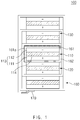
- FIG. 1 is a schematic cross-sectional view illustrating an example of an electrode assembly according to an embodiment of the present invention
- FIG. 2 is a schematic cross-sectional view of another example of the electrode assembly according to an embodiment of the present invention.
- an electrode assembly 100 comprises a plurality of unit cells 110, 120, 130, 140, and 150 and a separation film 160 folded to be disposed between the plurality of unit cells 110, 120, 130, 140, and 150.
- FIGS. 1 and 2 the electrode assembly according to an embodiment of the present invention will be described in more detail with reference to FIGS. 1 and 2 .
- Each of the unit cells 110, 120, 130, 140, and 150 is a chargeable/dischargeable power generation device and has a structure in which at least one electrode 113 and at least one separator 114 are assembled and alternately stacked.
- An electrode 113 may comprise a positive electrode 111 and a negative electrode 112. Also, the separator 114 separates the positive electrode 111 from the negative electrode 112 to electrically insulate the positive electrode 111 and the negative electrode from each other.
- one of the plurality of unit cells 110, 120, 130, 140, and 150 may comprise at least one positive electrode 111, at least one negative electrode 112, and at least one separator 114.
- the separator 114 is made of an insulation material, and also, the positive electrode 111, the separator 114, and the negative electrode 112 are alternately stacked.
- the separator 114 may be, for example, disposed between the positive electrode 111 and the negative electrode 112.
- the separator 114 may be disposed between the positive electrode 111 and the negative electrode 112 and also be disposed on outer surfaces of the positive electrode 111 and the negative electrode 112.
- the separator 114 may be a polyethylene film, a polypropylene film, or a multi-layered film obtained by combining the films, which has fine porosity, or a polymer film for a polymer electrolyte or a gel-type polymer electrolyte such as polyvinylidene fluoride, polyethylene oxide, polyacrylonitrile, or polyvinylidene fluoride hexafluoropropylene copolymer.
- a polymer film for a polymer electrolyte or a gel-type polymer electrolyte such as polyvinylidene fluoride, polyethylene oxide, polyacrylonitrile, or polyvinylidene fluoride hexafluoropropylene copolymer.
- the separation film 160 may be folded to be disposed between the plurality of unit cells 110, 120, 130, 140, and 150.
- the separation film 160 may be folded two times or more to come into contact with and surround the first unit cell 110, which is disposed at the initial position of the separation film 160, of the plurality of unit cells 110, 120, 130, 140, and 150.
- the separation film 160 may completely surround the exposed portion of the electrode 113 of the first unit cell 110 to prevent the electrode 113 from being damaged.
- the separation film 160 surrounding the first unit cell 110 may be prevented from being unfolded.
- the separation film 160 may comprise a first folding part 161 folded once to surround the first unit cell 110 and a second folding part 162 folded to additionally surround the first unit cell 110.
- first folding part 161 be provided to surround one surface and one side surface of the first unit cell 110
- second folding part 162 may be provided to surround the other surface and the other side surface of the second unit cell 120.
- first folding part 161 may be provided to surround a top surface and a left surface of the first unit cell 110, which are illustrated in FIG. 1
- second folding part 162 may be provided to surround a lower surface and a right surface of the first unit cell 110.
- an outer surface of the first folding part 161 in a folding direction is coated with an adhesion layer 161a to adhere to a portion of the separation film 160, which faces the outer surface of the first folding part 161 when the first folding part 161 is folded.
- the separation film 160 surrounding the first unit cell 110 may be more effectively prevented from being unfolded.
- first folding part 161 and the second folding part 162 may be provided to surround an entire outer circumference of the first unit cell 110.
- first and second folding parts 161 and 162 are shown as if in the separated shape in FIG. 1 , the first and second folding parts 161 and 162 may be portions of the long separation film 160 connected in one body.
- the electrode assembly 100 may further comprise a fixing tape 170 for preventing the folding of the separation film 160 from being unfolded.
- the fixing tape 170 may be attached from an end of the folded separation film 160 to a portion of the separation film, which is adjacent to the end.
- the separation film may be provided to surround the plurality of unit cells 110, 120, 130, 140, and 150 in the same direction. That is, the plurality of unit cells 110, 120, 130, 140, and 150 may be successively provided on one side surface of the separation film 160 and successively folded in one direction.
- the separation film 160 may surround the plurality of unit cells 110, 120, 130, 140, and 150, and the folded direction of the plurality of unit cells 110, 120, 130, 140, and 150 may be a clockwise direction or a counterclockwise direction.
- the separation film 260 may be provided to successively alternately surround the plurality of unit cells 110, 120, 130, 140, and 150 in different directions. That is, the separation film 160 may be provided to successively alternately surround the plurality of unit cells 110, 120, 130, 140, and 150 in the clockwise direction and the counterclockwise direction.
- the separation film 260 may surround the first unit cell 110 arranged at a first position in the counterclockwise direction, surround the second unit cell 120 arranged at a second position in the clockwise direction, surround the third unit cell 130 arranged at a third position again in the counterclockwise direction so that the separation film 260 successively surrounds the plurality of unit cells 110, 120, 130, 140, and 150.
- the portion of the separation film 260 which comprises the first folding part 261 and the second folding part 262, may surround the first unit cell 110. Additionally, the separation film 260 surrounds the entire circumference of the plurality of unit cells 110, 120, 130, 140, and 150 to form the electrode assembly 200.
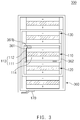
- FIG. 3 is a schematic cross-sectional view of an electrode assembly according to another embodiment of the present invention.
- an electrode assembly 300 according to another embodiment of the present invention comprises a plurality of unit cells 110, 120, 130, 140, and 150 and a separation film 360 folded to be disposed between the plurality of unit cells 110, 120, 130, 140, and 150.
- the electrode assembly 300 according to another embodiment of the present invention is different from the electrode assembly 100 according to the foregoing embodiment in that a first folding part 361 of the separation film 360 surrounds a first unit cell 110.
- the separation film 360 of the electrode assembly 300 comprises a first folding part 361 surrounding a portion of the first unit cell 110, which is disposed at an initial position of the separation film 360, of the plurality of unit cells 110, 120, 130, 140, and 150 and a second folding part 362.
- the first folding part 361 may be provided to surround an end of one surface (or a portion of a top surface) and one side surface of the first unit cell 110. That is, for example, the first folding part 361 may be provided to surround an end of the top surface and a left surface of the first unit cell 110 in FIG. 3 .
- an adhesive may be applied to an inner surface of the first folding part 361 in a folding direction to form an adhesion layer 361b.
- the first folding part 361 may adhere to the first unit cell 110 through the adhesion layer 361b.
- the first folding part 361 may be prevented from being unfloded in the first unit cell 110, and the separation film 360 surrounding the electrode assembly 300 may be prevented from being unfolded.
- the second folding part 362 is provided to surround the other surface and the other side surface of the second unit cell 120. That is, for example, the second folding part 362 may be provided to surround a bottom surface and a right surface of the first unit cell 110 in FIG. 3 .
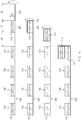
- FIG. 4 is a schematic cross-sectional view of a method for manufacturing an electrode assembly according to further another embodiment of the present invention.
- a method for manufacturing an electrode assembly comprises a preparation process of preparing a plurality of unit cells 110, 120, 130, 140, and 150 and a separation film 160 and a seating process of seating the plurality of unit cells 110, 120, 130, 140, and 150 on the separation film 160, and a folding process.
- the preparation process at least one positive electrode 111, at least one negative electrode 112, the plurality of unit cells 110, 120, 130, 140, and 150, each of which comprises at least one separator 114, and the separation film 160 are prepared.
- the separator 114 may be made of an insulation material, and the positive electrode 111, the separator 114, and the negative electrode 112 may be alternately stacked.
- the plurality of unit cells 110, 120, 130, 140, and 150 are successively seated on the separation film 160 in one direction.
- the plurality of unit cells 110, 120, 130, 140, and 150 may be successively arranged on the separation film 160.
- a distance between the first unit cell 110 and the second unit cell 120 adjacent to the first unit cell 110 of the plurality of unit cells 110, 120, 130, 140, and 150 is defined as a1
- a width of the first unit cell 110 is defined as w1
- a height of the first unit cell 110 is defined as h1
- the unit cells 110, 120, 130, 140, and 150 may be arranged to satisfy a following equation: 2*w1 + 4*h1 ⁇ a1.
- the first unit cell 110 may rotate at an angle of about 360 degree or more so that the separation film 160 surround a circumference of the first unit cell 110.
- the separation film 160 on which the plurality of unit cells 110, 120, 130, 140, and 150 are seated may be successively folded so that the separation film 160 is disposed between the plurality of unit cells 110, 120, 130, 140, and 150.
- the separation film 160 may be folded at least two times to come into contact with and surround the first unit cell 110, which is disposed at an initial portion of the separation film 160, of the plurality of unit cells 110, 120, 130, 140, and 150.
- the separation film 160 may comprise a first folding part 161 folded once to surround the first unit cell 110 and a second folding part 162 additionally folded one more time to surround the first unit cell 110.
- the folding process may comprise a first folding process of folding an end of the first separation film 160 in a direction of the first unit cell 110 to allow the first folding part 161 of the separation film 160 to surround one surface and one side surface of the first unit cell 110 and a second folding process of rotating the first unit cell 110 at an angle of about 180 degrees to allow the second folding part 162 of the separation film 160 to additionally surround a circumference of the first unit cell 110.
- the first folding process the first folding part 161 and the first unit cell 110 may rotate and be folded together.
- the first folding part 161 may be folded to surround the first unit cell 110.
- the folding process may comprise an adhesion layer applying process of applying an adhesion layer 161a to an outer surface with respect to the folding direction of the first folding part 161 and an adhesion process of adhering a portion of the separation film 160, which faces the first folding part 161, to the adhesion layer 161a, when folded.
- an adhesion layer applying process of applying an adhesion layer 161a to an outer surface with respect to the folding direction of the first folding part 161 and an adhesion process of adhering a portion of the separation film 160, which faces the first folding part 161, to the adhesion layer 161a, when folded.
- the first unit cell 110 which is disposed at the initial position of the separation film 160, is folded two times to allow the separation film 160 to surround an entire outer circumference of the first unit cell 110, prevent the separation film 160 surrounding the first unit cell 110, which is disposed at the initial position of the separation film 160, from being frequently unfolded, and prevent an electrode 113 of the first unit cell 110 from being easily exposed.
- the electrode assembly 100 and the secondary battery in which the electrode assembly 100 is mounted may be improved in stability through the strongly folded and coupled structure.
- FIG. 5 is a schematic cross-sectional view of a method for manufacturing an electrode assembly according to still another embodiment of the present invention.
- a method for manufacturing an electrode assembly comprises a preparation process of preparing a plurality of unit cells 110, 120, 130, 140, and 150 and a separation film 160, a seating process, and a folding process.
- the method for manufacturing the electrode assembly according to still another embodiment of the present invention is different from the method for manufacturing the electrode assembly according to further another embodiment of the present invention in that a first folding part of the separation film 160 surrounds a first unit cell 110 before the first unit cell 110 rotates.
- the separation film 160 may comprise a first folding part 161 folded once to surround the first unit cell 110 and a second folding part 162 additionally folded one more time to surround the first unit cell 110.
- the first unit cell 110 when the first unit cell 110 is seated on the separation film 160, the first unit cell 110 may be seated to be spaced a predetermined distance from an end of the separation film 160 so that the first folding part 161 of the separation film 160 is disposed between the first unit cell 110, which is disposed at an initial position of the separation film 160, and the end of the separation film 160.
- the plurality of unit cells 110, 120, 130, 140, and 150 may be successively arranged on the separation film 160.
- a distance between the first unit cell 110 and the second unit cell 120 adjacent to the first unit cell 110 of the plurality of unit cells 110, 120, 130, 140, and 150 is defined as a1
- a distance between the end of the separation film 160 and the first unit cell 110 is defined as a3
- a width of the first unit cell 110 is defined as w1
- a height of the first unit cell 110 is defined as h1
- the unit cells 110, 120, 130, 140, and 150 may be arranged to satisfy a following equation: 1*w1 + 3*h1 ⁇ a2 and 1*w1 + 1*h1 ⁇ a3.
- the folding process comprises a first folding process of folding first folding part 160 to the first unit cell 110 and a second folding process of rotating the first unit cell 110 at an angle of about 180 degrees to allow the second folding part to surround a circumference of the first unit cell 110.
- the first folding part 161 of the separation film 160 is folded to surround the first unit cell 110.
- the first folding part 161 may be folded to surround a side surface and one surface of the first unit cell 110. That is, for example, the first folding part 161 may be folded to surround a right surface and a top surface of the first unit cell 110 in FIG. 5 .
- FIG. 6 is a schematic cross-sectional view illustrating a method for manufacturing an electrode assembly according to even another embodiment of the present invention.
- a method for manufacturing an electrode assembly comprises a preparation process of preparing a plurality of unit cells 110, 120, 130, 140, and 150 and a separation film 360, a seating process, and a folding process.
- the folding process comprises a first folding process of performing folding once and a second folding process of performing folding two times.
- the method for manufacturing the electrode assembly according to even another embodiment of the present invention is different from the methods for manufacturing the electrode assembly according to further another and still another embodiments of the present invention in that a first folding part 361 of the separation film 360 is folded to an end of one surface and a side surface of the first unit cell 110.
- the first folding part 361 may be folded to surround an end of one surface (or a portion of a top surface) and one side surface of the first unit cell 110.
- exposure of an electrode 113 of the first unit cell 110 which is weak in the prior art, may be prevented, and also, the separation film 360 may be prevented from being unfolded after the folding.
- the first folding process may further comprise an adhesive applying process of applying an adhesive to an inner surface in the folding direction of the first folding part 361 to form an adhesion layer 361b and an adhesion process of adhering the first folding part 361 to the first unit cell 110 through the adhesion layer 361b.
- the first folding part 361 may be prevented from being unfolded from the first unit cell 110, and the separation film 360 surrounding the electrode assembly 300 may be prevented from being unfolded.
- air may be injected to the first folding part 361 of the separation film 360 to fold the first folding part 361 to the first unit cell 110.
- the air may be injected through an air compressor.
- the first folding part 361 may be folded to the first unit cell 110 through a zig.
- the first folding part 361 may be folded to the first unit cell 110 through an insertion mechanism.
- the first folding part 361 may be folded with force of gravity.
- the first folding part 361 when the first folding part 361 is horizontally disposed, and a portion expect for the first folding part is fixed, the first folding part 361 may be folded with the force of gravity. That is, the portion except for the folding portion may be fixed, and the folding portion may be horizontally disposed to fold the first folding part 361 by using the force of gravity.
Landscapes
- Chemical & Material Sciences (AREA)
- Chemical Kinetics & Catalysis (AREA)
- Electrochemistry (AREA)
- General Chemical & Material Sciences (AREA)
- Engineering & Computer Science (AREA)
- Manufacturing & Machinery (AREA)
- Secondary Cells (AREA)
- Cell Separators (AREA)
Abstract
Description
- This application claims the priority of Korean Patent Application No.
10-2016-0147929 filed on November 08, 2016 - The present invention relates to an electrode assembly and a method for manufacturing the same.
- Secondary batteries are rechargeable unlike primarily batteries, and also, many studies on secondary batteries are being carried out in recent years due to the possibility of compact size and large capacity. As technology development and demands for mobile devices increase, demands for secondary batteries as energy source are rapidly increasing.
- Secondary batteries are classified into coin type batteries, cylindrical type batteries, prismatic type batteries, and pouch type batteries according to a shape of a battery case. In such a secondary battery, an electrode assembly mounted in a battery case is a chargeable and dischargeable power generating device having a structure in which an electrode and a separator are laminated.
- The electrode assembly may be approximately classified into a jelly-roll type electrode assembly in which a separator is interposed between a positive electrode and a negative electrode, each of which is provided as the form of a sheet coated with an active material, and then, the positive electrode, the separator, and the negative electrode are wound, a stack type electrode assembly in which a plurality of positive and negative electrodes with a separator therebetween are sequentially stacked, and a stack/folding type electrode assembly in which stack type unit cells are wound with a separation film having a long length. Among them, the jelly-roll type electrode assembly is widely used because it has an advantage of being easily manufactured and having high energy density per weight.
- An aspect of the present invention provides an electrode assembly in which a separation film is prevented from unfolded when a plurality of unit cells are folded together with the separation film, and an electrode is not exposed, and a method for manufacturing the same.
- According to another aspect of the present invention, there is provided an electrode assembly comprising: a plurality of unit cells comprising at least one positive electrode, at least one negative electrode, and at least one separator, respectively; and a separation film folded to be disposed between the plurality of unit cells, wherein the separation film is folded two times or more to come into contact with and surround a first unit cell, which is disposed at an initial position of the separation film, of the plurality of unit cells.
- According to another aspect of the present invention, there is provided a method for manufacturing an electrode assembly, the method comprising: preparing a plurality of unit cells, each of which comprises at least one positive electrode, at least one negative electrode, and at least one separator, and a separation film; seating the plurality of unit cells on one surface of the separation film; and successively folding the separation film on which the unit cells are seated so that the separation film is disposed between the plurality of unit cells, wherein, in the folding, the separation film is folded two times or more to come into contact with and surround a first unit cell, which is disposed at an initial position of the separation film, of the plurality of unit cells.
- According to the present invention, in the electrode assembly in which the plurality of unit cells together with the separation film are folded, the separation film surrounding the unit cell that is disposed at the initial position of the separation film may be prevented from being unfolded, and the electrode may not be exposed to improve stability of the electrode assembly.
-
-
FIG. 1 is a schematic cross-sectional view illustrating an example of an electrode assembly according to an embodiment of the present invention; -
FIG. 2 is a schematic cross-sectional view of another example of the electrode assembly according to an embodiment of the present invention; -
FIG. 3 is a schematic cross-sectional view of an electrode assembly according to another embodiment of the present invention; -
FIG. 4 is a schematic cross-sectional view illustrating a method for manufacturing an electrode assembly according to further another embodiment of the present invention; -
FIG. 5 is a schematic cross-sectional view illustrating a method for manufacturing an electrode assembly according to still another embodiment of the present invention; and -
FIG. 6 is a schematic cross-sectional view illustrating a method for manufacturing an electrode assembly according to even another embodiment of the present invention. - The objects, other objectives, features, and advantages of the present invention will be understood without difficulties through preferred embodiments below related to the accompanying drawings. It is noted that the same or similar components in the drawings are designated by the same reference numerals as far as possible even if they are shown in different drawings. The present invention may, however, be embodied in different forms and should not be construed as limited to the embodiments set forth herein. Moreover, detailed descriptions related to well-known functions or configurations will be ruled out in order not to unnecessarily obscure subject matters of the present disclosure.
-
FIG. 1 is a schematic cross-sectional view illustrating an example of an electrode assembly according to an embodiment of the present invention, andFIG. 2 is a schematic cross-sectional view of another example of the electrode assembly according to an embodiment of the present invention. - Referring to
FIG. 1 , anelectrode assembly 100 according to an embodiment of the present invention comprises a plurality ofunit cells separation film 160 folded to be disposed between the plurality ofunit cells - Hereinafter, the electrode assembly according to an embodiment of the present invention will be described in more detail with reference to
FIGS. 1 and2 . - Each of the
unit cells electrode 113 and at least oneseparator 114 are assembled and alternately stacked. - An
electrode 113 may comprise apositive electrode 111 and anegative electrode 112. Also, theseparator 114 separates thepositive electrode 111 from thenegative electrode 112 to electrically insulate thepositive electrode 111 and the negative electrode from each other. - Thus, one of the plurality of
unit cells positive electrode 111, at least onenegative electrode 112, and at least oneseparator 114. - The
separator 114 is made of an insulation material, and also, thepositive electrode 111, theseparator 114, and thenegative electrode 112 are alternately stacked. - Also, the
separator 114 may be, for example, disposed between thepositive electrode 111 and thenegative electrode 112. - Furthermore, for another example, the
separator 114 may be disposed between thepositive electrode 111 and thenegative electrode 112 and also be disposed on outer surfaces of thepositive electrode 111 and thenegative electrode 112. - For example, the
separator 114 may be a polyethylene film, a polypropylene film, or a multi-layered film obtained by combining the films, which has fine porosity, or a polymer film for a polymer electrolyte or a gel-type polymer electrolyte such as polyvinylidene fluoride, polyethylene oxide, polyacrylonitrile, or polyvinylidene fluoride hexafluoropropylene copolymer. - The
separation film 160 may be folded to be disposed between the plurality ofunit cells - Also, the
separation film 160 may be folded two times or more to come into contact with and surround thefirst unit cell 110, which is disposed at the initial position of theseparation film 160, of the plurality ofunit cells separation film 160 may completely surround the exposed portion of theelectrode 113 of thefirst unit cell 110 to prevent theelectrode 113 from being damaged. Also, theseparation film 160 surrounding thefirst unit cell 110 may be prevented from being unfolded. - The
separation film 160 may comprise afirst folding part 161 folded once to surround thefirst unit cell 110 and asecond folding part 162 folded to additionally surround thefirst unit cell 110. - Here, the
first folding part 161 be provided to surround one surface and one side surface of thefirst unit cell 110, and thesecond folding part 162 may be provided to surround the other surface and the other side surface of thesecond unit cell 120. Here, for example, thefirst folding part 161 may be provided to surround a top surface and a left surface of thefirst unit cell 110, which are illustrated inFIG. 1 , and thesecond folding part 162 may be provided to surround a lower surface and a right surface of thefirst unit cell 110. - Furthermore, an outer surface of the
first folding part 161 in a folding direction is coated with anadhesion layer 161a to adhere to a portion of theseparation film 160, which faces the outer surface of thefirst folding part 161 when thefirst folding part 161 is folded. Thus, theseparation film 160 surrounding thefirst unit cell 110 may be more effectively prevented from being unfolded. - Also, the
first folding part 161 and thesecond folding part 162 may be provided to surround an entire outer circumference of thefirst unit cell 110. For reference, although the first andsecond folding parts FIG. 1 , the first andsecond folding parts long separation film 160 connected in one body. - Referring to
FIG. 1 , theelectrode assembly 100 according to an embodiment of the present invention may further comprise afixing tape 170 for preventing the folding of theseparation film 160 from being unfolded. Here, thefixing tape 170 may be attached from an end of the foldedseparation film 160 to a portion of the separation film, which is adjacent to the end. - For example, referring to
FIG.1 , the separation film may be provided to surround the plurality ofunit cells unit cells separation film 160 and successively folded in one direction. Here, for example, theseparation film 160 may surround the plurality ofunit cells unit cells - Also, for another example, referring to
FIG. 2 , theseparation film 260 may be provided to successively alternately surround the plurality ofunit cells separation film 160 may be provided to successively alternately surround the plurality ofunit cells separation film 260 may surround thefirst unit cell 110 arranged at a first position in the counterclockwise direction, surround thesecond unit cell 120 arranged at a second position in the clockwise direction, surround thethird unit cell 130 arranged at a third position again in the counterclockwise direction so that theseparation film 260 successively surrounds the plurality ofunit cells separation film 260, which comprises thefirst folding part 261 and thesecond folding part 262, may surround thefirst unit cell 110. Additionally, theseparation film 260 surrounds the entire circumference of the plurality ofunit cells electrode assembly 200. -
FIG. 3 is a schematic cross-sectional view of an electrode assembly according to another embodiment of the present invention. - Referring to
FIG. 3 , anelectrode assembly 300 according to another embodiment of the present invention comprises a plurality ofunit cells separation film 360 folded to be disposed between the plurality ofunit cells - The
electrode assembly 300 according to another embodiment of the present invention is different from theelectrode assembly 100 according to the foregoing embodiment in that afirst folding part 361 of theseparation film 360 surrounds afirst unit cell 110. - Thus, in this embodiment, descriptions duplicated with those according to the foregoing embodiment will be briefly described, and also, a difference will be mainly described.
- The
separation film 360 of theelectrode assembly 300 according to another embodiment comprises afirst folding part 361 surrounding a portion of thefirst unit cell 110, which is disposed at an initial position of theseparation film 360, of the plurality ofunit cells second folding part 362. - Here, the
first folding part 361 may be provided to surround an end of one surface (or a portion of a top surface) and one side surface of thefirst unit cell 110. That is, for example, thefirst folding part 361 may be provided to surround an end of the top surface and a left surface of thefirst unit cell 110 inFIG. 3 . - Also, an adhesive may be applied to an inner surface of the
first folding part 361 in a folding direction to form anadhesion layer 361b. Thus, thefirst folding part 361 may adhere to thefirst unit cell 110 through theadhesion layer 361b. Thus, thefirst folding part 361 may be prevented from being unfloded in thefirst unit cell 110, and theseparation film 360 surrounding theelectrode assembly 300 may be prevented from being unfolded. - The
second folding part 362 is provided to surround the other surface and the other side surface of thesecond unit cell 120. That is, for example, thesecond folding part 362 may be provided to surround a bottom surface and a right surface of thefirst unit cell 110 inFIG. 3 . -
FIG. 4 is a schematic cross-sectional view of a method for manufacturing an electrode assembly according to further another embodiment of the present invention. - Referring to
FIG. 4 , a method for manufacturing an electrode assembly according to further another embodiment of the present invention comprises a preparation process of preparing a plurality ofunit cells separation film 160 and a seating process of seating the plurality ofunit cells separation film 160, and a folding process. - Hereinafter, the method for manufacturing the electrode assembly according to further another embodiment of the present invention will be described in more detail.
- In more detail, referring to
FIG. 4 , in the preparation process, at least onepositive electrode 111, at least onenegative electrode 112, the plurality ofunit cells separator 114, and theseparation film 160 are prepared. Here, theseparator 114 may be made of an insulation material, and thepositive electrode 111, theseparator 114, and thenegative electrode 112 may be alternately stacked. - In the seating process, the plurality of
unit cells separation film 160 in one direction. - Also, in the seating process, the plurality of
unit cells separation film 160. Here, when a distance between thefirst unit cell 110 and thesecond unit cell 120 adjacent to thefirst unit cell 110 of the plurality ofunit cells first unit cell 110 is defined as w1, and a height of thefirst unit cell 110 is defined as h1, theunit cells - Furthermore, in the folding process, the
first unit cell 110 may rotate at an angle of about 360 degree or more so that theseparation film 160 surround a circumference of thefirst unit cell 110. - In the folding process, the
separation film 160 on which the plurality ofunit cells separation film 160 is disposed between the plurality ofunit cells - Also, in the folding process, the
separation film 160 may be folded at least two times to come into contact with and surround thefirst unit cell 110, which is disposed at an initial portion of theseparation film 160, of the plurality ofunit cells separation film 160 may comprise afirst folding part 161 folded once to surround thefirst unit cell 110 and asecond folding part 162 additionally folded one more time to surround thefirst unit cell 110. - Also, the folding process may comprise a first folding process of folding an end of the
first separation film 160 in a direction of thefirst unit cell 110 to allow thefirst folding part 161 of theseparation film 160 to surround one surface and one side surface of thefirst unit cell 110 and a second folding process of rotating thefirst unit cell 110 at an angle of about 180 degrees to allow thesecond folding part 162 of theseparation film 160 to additionally surround a circumference of thefirst unit cell 110. Here, in the first folding process, thefirst folding part 161 and thefirst unit cell 110 may rotate and be folded together. Here, thefirst folding part 161 may be folded to surround thefirst unit cell 110. - The folding process may comprise an adhesion layer applying process of applying an
adhesion layer 161a to an outer surface with respect to the folding direction of thefirst folding part 161 and an adhesion process of adhering a portion of theseparation film 160, which faces thefirst folding part 161, to theadhesion layer 161a, when folded. Thus, thefirst folding part 161 surrounding thefirst unit cell 110 may be effectively prevented from being unfolded. - Referring to
FIGS. 1 and4 , in the method for manufacturing the electrode assembly according to further another embodiment, when theseparation film 160 and the plurality ofunit cells first unit cell 110, which is disposed at the initial position of theseparation film 160, is folded two times to allow theseparation film 160 to surround an entire outer circumference of thefirst unit cell 110, prevent theseparation film 160 surrounding thefirst unit cell 110, which is disposed at the initial position of theseparation film 160, from being frequently unfolded, and prevent anelectrode 113 of thefirst unit cell 110 from being easily exposed. Also, theelectrode assembly 100 and the secondary battery in which theelectrode assembly 100 is mounted may be improved in stability through the strongly folded and coupled structure. -
FIG. 5 is a schematic cross-sectional view of a method for manufacturing an electrode assembly according to still another embodiment of the present invention. - Referring to
FIG. 5 , a method for manufacturing an electrode assembly according to still another embodiment of the present invention comprises a preparation process of preparing a plurality ofunit cells separation film 160, a seating process, and a folding process. - The method for manufacturing the electrode assembly according to still another embodiment of the present invention is different from the method for manufacturing the electrode assembly according to further another embodiment of the present invention in that a first folding part of the
separation film 160 surrounds afirst unit cell 110 before thefirst unit cell 110 rotates. - Thus, in this embodiment, descriptions duplicated with those according to further another embodiment will be briefly described, and also, a difference will be mainly described.
- Referring to
FIGS. 1 and5 , in the seating process, the plurality ofunit cells separation film 160. Here, theseparation film 160 may comprise afirst folding part 161 folded once to surround thefirst unit cell 110 and asecond folding part 162 additionally folded one more time to surround thefirst unit cell 110. Here, when thefirst unit cell 110 is seated on theseparation film 160, thefirst unit cell 110 may be seated to be spaced a predetermined distance from an end of theseparation film 160 so that thefirst folding part 161 of theseparation film 160 is disposed between thefirst unit cell 110, which is disposed at an initial position of theseparation film 160, and the end of theseparation film 160. - Also, referring to
FIG. 5(a) , in the seating process, the plurality ofunit cells separation film 160. Here, when a distance between thefirst unit cell 110 and thesecond unit cell 120 adjacent to thefirst unit cell 110 of the plurality ofunit cells separation film 160 and thefirst unit cell 110 is defined as a3, a width of thefirst unit cell 110 is defined as w1, and a height of thefirst unit cell 110 is defined as h1, theunit cells - The folding process comprises a first folding process of folding
first folding part 160 to thefirst unit cell 110 and a second folding process of rotating thefirst unit cell 110 at an angle of about 180 degrees to allow the second folding part to surround a circumference of thefirst unit cell 110. - Here, in the first folding process, the
first folding part 161 of theseparation film 160 is folded to surround thefirst unit cell 110. Here, for example, thefirst folding part 161 may be folded to surround a side surface and one surface of thefirst unit cell 110. That is, for example, thefirst folding part 161 may be folded to surround a right surface and a top surface of thefirst unit cell 110 inFIG. 5 . -
FIG. 6 is a schematic cross-sectional view illustrating a method for manufacturing an electrode assembly according to even another embodiment of the present invention. - Referring to
FIG. 6 , a method for manufacturing an electrode assembly according to even another embodiment of the present invention comprises a preparation process of preparing a plurality ofunit cells separation film 360, a seating process, and a folding process. Here, the folding process comprises a first folding process of performing folding once and a second folding process of performing folding two times. - The method for manufacturing the electrode assembly according to even another embodiment of the present invention is different from the methods for manufacturing the electrode assembly according to further another and still another embodiments of the present invention in that a
first folding part 361 of theseparation film 360 is folded to an end of one surface and a side surface of thefirst unit cell 110. - Thus, in this embodiment, descriptions duplicated with those according to further another and still another embodiments will be briefly described, and also, a difference will be mainly described.
- Referring to
FIGS. 3 and6 , in the method for manufacturing the electrode assembly according to even another embodiment of the present invention, in the first folding process, thefirst folding part 361 may be folded to surround an end of one surface (or a portion of a top surface) and one side surface of thefirst unit cell 110. Thus, exposure of anelectrode 113 of thefirst unit cell 110, which is weak in the prior art, may be prevented, and also, theseparation film 360 may be prevented from being unfolded after the folding. - Also, the first folding process may further comprise an adhesive applying process of applying an adhesive to an inner surface in the folding direction of the
first folding part 361 to form anadhesion layer 361b and an adhesion process of adhering thefirst folding part 361 to thefirst unit cell 110 through theadhesion layer 361b. Thus, thefirst folding part 361 may be prevented from being unfolded from thefirst unit cell 110, and theseparation film 360 surrounding theelectrode assembly 300 may be prevented from being unfolded. - In the first folding process, for example, air may be injected to the
first folding part 361 of theseparation film 360 to fold thefirst folding part 361 to thefirst unit cell 110. Here, the air may be injected through an air compressor. - Also, in the first folding process, for another example, the
first folding part 361 may be folded to thefirst unit cell 110 through a zig. - Furthermore, in the first folding process, for further another example, the
first folding part 361 may be folded to thefirst unit cell 110 through an insertion mechanism. - Also, in the first folding process, for further another example, the
first folding part 361 may be folded with force of gravity. Here, when thefirst folding part 361 is horizontally disposed, and a portion expect for the first folding part is fixed, thefirst folding part 361 may be folded with the force of gravity. That is, the portion except for the folding portion may be fixed, and the folding portion may be horizontally disposed to fold thefirst folding part 361 by using the force of gravity.
Claims (16)
- A method for manufacturing an electrode assembly, the method comprising:preparing a plurality of unit cells, each of which comprises at least one positive electrode, at least one negative electrode, and at least one separator, and a separation film;seating the plurality of unit cells on one surface of the separation film; andsuccessively folding the separation film on which the unit cells are seated so that the separation film is disposed between the plurality of unit cells,wherein, in the folding, the separation film is folded two times or more to come into contact with and surround a first unit cell, which is disposed at an initial position of the separation film, of the plurality of unit cells.
- The method of claim 1, wherein, in the seating, the plurality of unit cells are successively arranged on the separation film, and
when a distance between the first unit cell and a second unit cell adjacent to the first unit cell of the plurality of unit cells is defined as a1, a width of the first unit cell is defined as w1, and a height of the first unit cell is defined as h1, the unit cells are arranged to satisfy a following equation: 2*w1 + 4*h1 < a1. - The method of claim 1, wherein, in the folding, the first unit cell rotates at an angle of about 360 degrees or more to allow the separation film to surround a circumference of the first unit cell.
- The method of claim 1, wherein, in the seating, the plurality of unit cells are successively arranged on the separation film, and
when a distance between the first unit cell and a second unit cell adjacent to the first unit cell of the plurality of unit cells is defined as a1, a distance between an end of the separation film and the first unit cell is defined as a3, a width of the first unit cell is defined as w1, and a height of the first unit cell is defined as h1, the unit cells are arranged to satisfy a following equation: 1*w1 + 3*h1 < a2 and 1*w1 + 1*h1 < a3. - The method of claim 1, wherein the folding comprises:a first folding process of folding an end of the first separation film toward the first unit cell to allow a first folding part of the separation film to surround one surface and one side surface of the first unit cell; anda second folding process of rotating the first unit cell at an angle of about 180 degrees to allow a second folding part of the separation film to additionally surround a circumference of the first unit cell.
- The method of claim 5, wherein, in the first folding process, the first folding part surrounds an end of the one surface and the one side surface of the first unit cell.
- The method of claim 6, wherein, in the first folding process, air is injected to the first folding part of the separation film to fold the first folding part to the first unit cell.
- The method of claim 6, wherein, in the first folding process, the first folding part is folded to the first unit cell through a zig.
- The method of claim 1, wherein the separation film comprises a first folding part folded once to surround the first unit cell and a second folding part additionally folded one more time to surround the first unit cell, and
the folding further comprises:applying an adhesion layer to an outer surface in a folding direction of the first folding part; andadhering a portion of the separation film, which faces the first folding part, to the adhesion layer when folded. - The method of any one of claims 5 to 9, wherein the first folding process further comprises:applying the adhesion layer to an inner surface in the folding direction of the first folding part to form an adhesion layer; andadhering the first folding part to the first unit cell through the adhesion layer.
- An electrode assembly comprising:a plurality of unit cells comprising at least one positive electrode, at least one negative electrode, and at least one separator, respectively; anda separation film folded to be disposed between the plurality of unit cells,wherein the separation film is folded two times or more to come into contact with and surround a first unit cell, which is disposed at an initial position of the separation film, of the plurality of unit cells.
- The electrode assembly of claim 11, wherein the separation film comprises a first folding part folded once to surround the first unit cell and a second folding part additionally folded one more time to surround the first unit cell.
- The electrode assembly of claim 12, wherein the first folding part adheres to a portion of the separation film, which faces the first folding part when folded, by applying an adhesion layer to an outer surface thereof in a folding direction.
- The electrode assembly of claim 12, wherein the first folding part and the second folding part surround an entire outer circumference of the first unit cell.
- The electrode assembly of claim 12, wherein the first folding part surround an end of one surface and one side surface of the first unit cell, and
the second folding part surrounds the other surface and the other side surface of the first unit cell. - The electrode assembly of claim 12, wherein an adhesion layer is disposed on an inner surface of the first folding part in a folding direction so that the first folding part adheres to the first unit cell through an adhesion layer.
Priority Applications (1)
| Application Number | Priority Date | Filing Date | Title |
|---|---|---|---|
| PL17869470T PL3416225T3 (en) | 2016-11-08 | 2017-10-24 | Electrode assembly and manufacturing method therefor |
Applications Claiming Priority (2)
| Application Number | Priority Date | Filing Date | Title |
|---|---|---|---|
| KR1020160147929A KR102068710B1 (en) | 2016-11-08 | 2016-11-08 | Electrode assembly and the manufacturing method |
| PCT/KR2017/011780 WO2018088722A1 (en) | 2016-11-08 | 2017-10-24 | Electrode assembly and manufacturing method therefor |
Publications (3)
| Publication Number | Publication Date |
|---|---|
| EP3416225A1 true EP3416225A1 (en) | 2018-12-19 |
| EP3416225A4 EP3416225A4 (en) | 2019-05-22 |
| EP3416225B1 EP3416225B1 (en) | 2020-04-15 |
Family
ID=62064685
Family Applications (1)
| Application Number | Title | Priority Date | Filing Date |
|---|---|---|---|
| EP17869470.9A Active EP3416225B1 (en) | 2016-11-08 | 2017-10-24 | Electrode assembly and manufacturing method therefor |
Country Status (7)
| Country | Link |
|---|---|
| US (1) | US10923697B2 (en) |
| EP (1) | EP3416225B1 (en) |
| JP (1) | JP6693649B2 (en) |
| KR (1) | KR102068710B1 (en) |
| CN (2) | CN115020627B (en) |
| PL (1) | PL3416225T3 (en) |
| WO (1) | WO2018088722A1 (en) |
Families Citing this family (11)
| Publication number | Priority date | Publication date | Assignee | Title |
|---|---|---|---|---|
| US20200243895A1 (en) * | 2017-09-29 | 2020-07-30 | Envision Aesc Energy Devices Ltd. | Secondary battery |
| KR102861462B1 (en) * | 2019-06-25 | 2025-09-17 | 주식회사 엘지에너지솔루션 | Bipolar electrode assembly, manufacturing method of the same, and bipolar battery comprising the same |
| CN111934026B (en) * | 2020-07-30 | 2021-11-30 | 宁德新能源科技有限公司 | Battery cell structure and electrochemical device |
| KR102888921B1 (en) | 2020-09-23 | 2025-11-20 | 주식회사 엘지에너지솔루션 | Rechargeable battery manufacturing method and rechargeable battery |
| US20230268627A1 (en) | 2020-09-23 | 2023-08-24 | Lg Energy Solution, Ltd. | Method for Manufacturing Secondary Battery and Secondary Battery |
| US12552150B2 (en) | 2021-03-15 | 2026-02-17 | Lg Energy Solution, Ltd. | Plasma generation device and facility for manufacturing electrode assembly including the same |
| KR102837052B1 (en) * | 2021-03-15 | 2025-07-23 | 주식회사 엘지에너지솔루션 | Plasma generating apparatus and electrode assembly manufacturing equipment including the same |
| KR102831130B1 (en) * | 2021-08-13 | 2025-07-04 | 주식회사 엘지에너지솔루션 | Electrode assembly for secondary battery and method for manufacturing the same |
| CN117413390A (en) * | 2021-12-23 | 2024-01-16 | 株式会社Lg新能源 | Electrode assembly and manufacturing method thereof |
| KR20230108138A (en) * | 2022-01-10 | 2023-07-18 | 에스케이온 주식회사 | Battery cell and battery module comprising the same |
| CN117855622A (en) * | 2024-01-04 | 2024-04-09 | 合肥国轩高科动力能源有限公司 | Laminated battery cell, method for preparing laminated battery cell, and system for preparing laminated battery cell |
Family Cites Families (24)
| Publication number | Priority date | Publication date | Assignee | Title |
|---|---|---|---|---|
| KR100515572B1 (en) * | 2000-02-08 | 2005-09-20 | 주식회사 엘지화학 | Stacked electrochemical cell and method for preparing the same |
| KR20010008205A (en) * | 2000-11-15 | 2001-02-05 | 유성림 | Method for medical treatment service using of computer network, system and computer-readable medium recording the method |
| KR100388648B1 (en) * | 2001-05-23 | 2003-06-25 | 주식회사 코캄엔지니어링 | Automated manufacturing system of lithium secondary cell |
| KR100646535B1 (en) * | 2005-03-23 | 2006-11-23 | 삼성에스디아이 주식회사 | Electrode assembly for lithium ion battery and lithium ion secondary battery using same |
| KR100948972B1 (en) * | 2005-11-03 | 2010-03-23 | 주식회사 엘지화학 | Secondary battery consisting of separator with folding part |
| KR100861705B1 (en) * | 2006-05-29 | 2008-10-06 | 주식회사 엘지화학 | Electrode assembly having excellent structural stability and wettability of electrolyte and secondary battery comprising the same |
| KR100987300B1 (en) * | 2007-07-04 | 2010-10-12 | 주식회사 엘지화학 | Stack-Folded Electrode Assembly and Method of Manufacturing the Same |
| KR101150265B1 (en) * | 2007-07-16 | 2012-06-12 | 주식회사 엘지화학 | Stack/folding-typed electrode assembly of noble structure and method for preparation of the same |
| KR101014817B1 (en) * | 2007-12-14 | 2011-02-14 | 주식회사 엘지화학 | Stacked / Foldable Electrode Assembly with Safety Member and Method of Manufacturing the Same |
| KR101278739B1 (en) * | 2008-11-07 | 2013-06-25 | 주식회사 엘지화학 | Stacked electrochemical cell |
| KR101367754B1 (en) * | 2011-07-07 | 2014-02-27 | 주식회사 엘지화학 | Electrode assembly for electrochemical device and electrochemical device comprising the same |
| KR101332282B1 (en) * | 2012-03-14 | 2013-11-22 | 주식회사 엘지화학 | Electrode Assembly of Novel Structure and Battery Cell Comprising the Same |
| CN104247141B (en) * | 2012-05-07 | 2018-04-27 | 株式会社Lg 化学 | Electrode assemblie and the lithium secondary battery including the electrode assemblie |
| KR20130135017A (en) * | 2012-05-31 | 2013-12-10 | 주식회사 엘지화학 | A stepwise electrode assembly, and battery cell, battery pack and device comprising the same |
| DE102012019975B3 (en) * | 2012-10-04 | 2013-11-14 | Jonas & Redmann Automationstechnik Gmbh | Device for producing electrode stacks |
| KR101668356B1 (en) * | 2013-10-08 | 2016-10-21 | 주식회사 엘지화학 | Stack-folding typed electrode assembly and manufacturing methods thereof |
| KR101645065B1 (en) * | 2013-10-21 | 2016-08-02 | 주식회사 엘지화학 | Stack-folding type electrode assembly and manufacturing method thereof |
| KR101676406B1 (en) * | 2013-10-31 | 2016-11-15 | 주식회사 엘지화학 | Stack-folding typed electrode assembly |
| KR101826894B1 (en) * | 2013-11-04 | 2018-02-07 | 주식회사 엘지화학 | Electrode assembly and apparatus for manufacturing the same |
| KR101692776B1 (en) * | 2014-05-15 | 2017-01-17 | 주식회사 엘지화학 | Battery Cell Comprising Tetra cell |
| KR101706319B1 (en) * | 2014-05-22 | 2017-02-13 | 주식회사 엘지화학 | Electrode Assembly and Composite Electrode Assembly of Stair-like Structure |
| KR101684283B1 (en) | 2014-07-18 | 2016-12-08 | 주식회사 엘지화학 | Jelly-roll type electrode assembly |
| KR101710060B1 (en) * | 2014-08-13 | 2017-02-24 | 주식회사 엘지화학 | Stack and folding-type electrode assembly and method for fabricating the same |
| US9614248B2 (en) * | 2014-08-13 | 2017-04-04 | Lg Chem, Ltd. | Stack-folding type electrode assembly and method of manufacturing the same |
-
2016
- 2016-11-08 KR KR1020160147929A patent/KR102068710B1/en active Active
-
2017
- 2017-10-24 JP JP2018547369A patent/JP6693649B2/en active Active
- 2017-10-24 EP EP17869470.9A patent/EP3416225B1/en active Active
- 2017-10-24 CN CN202210519479.4A patent/CN115020627B/en active Active
- 2017-10-24 PL PL17869470T patent/PL3416225T3/en unknown
- 2017-10-24 CN CN201780058990.6A patent/CN110178257B/en active Active
- 2017-10-24 WO PCT/KR2017/011780 patent/WO2018088722A1/en not_active Ceased
- 2017-11-07 US US15/805,771 patent/US10923697B2/en active Active
Also Published As
| Publication number | Publication date |
|---|---|
| PL3416225T3 (en) | 2020-11-16 |
| EP3416225A4 (en) | 2019-05-22 |
| EP3416225B1 (en) | 2020-04-15 |
| CN110178257B (en) | 2022-05-31 |
| JP6693649B2 (en) | 2020-05-13 |
| WO2018088722A1 (en) | 2018-05-17 |
| KR102068710B1 (en) | 2020-01-22 |
| US20180130985A1 (en) | 2018-05-10 |
| JP2019507948A (en) | 2019-03-22 |
| US10923697B2 (en) | 2021-02-16 |
| CN115020627B (en) | 2024-03-08 |
| CN115020627A (en) | 2022-09-06 |
| KR20180051072A (en) | 2018-05-16 |
| CN110178257A (en) | 2019-08-27 |
Similar Documents
| Publication | Publication Date | Title |
|---|---|---|
| EP3416225B1 (en) | Electrode assembly and manufacturing method therefor | |
| KR102493260B1 (en) | Longitudinal Constraints for Energy Storage Devices | |
| CN108808059B (en) | Laminated secondary battery based on cross stacking and preparation method thereof | |
| JP7221122B2 (en) | Battery cell electrode assembly manufacturing method and battery cell | |
| JP7446444B2 (en) | Electrode assembly including disconnection prevention layer and method for manufacturing the same | |
| KR102155163B1 (en) | Electrode assembly | |
| US20220238924A1 (en) | Method for Manufacturing Secondary Battery and Secondary Battery | |
| US11362383B2 (en) | Secondary battery | |
| KR20190071129A (en) | Electrode assembly and rechargeable battery comprising the same | |
| JP7648111B2 (en) | Electrode assembly with coating for preventing short circuit | |
| EP3518335B1 (en) | Lithium secondary battery including cylindrical jelly roll | |
| EP4174995A1 (en) | Secondary battery manufacturing method and secondary battery | |
| US20230261266A1 (en) | Electrode assembly and secondary battery including the same | |
| JPH097610A (en) | Battery | |
| KR20250143645A (en) | Electrode Assembly and Method for Manufacturing the Same | |
| JP2023536533A (en) | Method for manufacturing secondary battery and secondary battery | |
| KR102167116B1 (en) | Electrode assembly and the manufacturing method | |
| KR101781258B1 (en) | Jelly-roll type electrode assembly |
Legal Events
| Date | Code | Title | Description |
|---|---|---|---|
| STAA | Information on the status of an ep patent application or granted ep patent |
Free format text: STATUS: THE INTERNATIONAL PUBLICATION HAS BEEN MADE |
|
| PUAI | Public reference made under article 153(3) epc to a published international application that has entered the european phase |
Free format text: ORIGINAL CODE: 0009012 |
|
| STAA | Information on the status of an ep patent application or granted ep patent |
Free format text: STATUS: REQUEST FOR EXAMINATION WAS MADE |
|
| 17P | Request for examination filed |
Effective date: 20180911 |
|
| AK | Designated contracting states |
Kind code of ref document: A1 Designated state(s): AL AT BE BG CH CY CZ DE DK EE ES FI FR GB GR HR HU IE IS IT LI LT LU LV MC MK MT NL NO PL PT RO RS SE SI SK SM TR |
|
| AX | Request for extension of the european patent |
Extension state: BA ME |
|
| A4 | Supplementary search report drawn up and despatched |
Effective date: 20190418 |
|
| RIC1 | Information provided on ipc code assigned before grant |
Ipc: H01M 2/16 20060101ALN20190412BHEP Ipc: H01M 2/02 20060101ALI20190412BHEP Ipc: H01M 10/04 20060101AFI20190412BHEP Ipc: H01M 6/46 20060101ALI20190412BHEP |
|
| GRAP | Despatch of communication of intention to grant a patent |
Free format text: ORIGINAL CODE: EPIDOSNIGR1 |
|
| STAA | Information on the status of an ep patent application or granted ep patent |
Free format text: STATUS: GRANT OF PATENT IS INTENDED |
|
| RIC1 | Information provided on ipc code assigned before grant |
Ipc: H01M 6/46 20060101ALI20191126BHEP Ipc: H01M 2/16 20060101ALN20191126BHEP Ipc: H01M 10/04 20060101AFI20191126BHEP Ipc: H01M 2/02 20060101ALI20191126BHEP |
|
| DAV | Request for validation of the european patent (deleted) | ||
| DAX | Request for extension of the european patent (deleted) | ||
| INTG | Intention to grant announced |
Effective date: 20191216 |
|
| GRAS | Grant fee paid |
Free format text: ORIGINAL CODE: EPIDOSNIGR3 |
|
| GRAA | (expected) grant |
Free format text: ORIGINAL CODE: 0009210 |
|
| STAA | Information on the status of an ep patent application or granted ep patent |
Free format text: STATUS: THE PATENT HAS BEEN GRANTED |
|
| AK | Designated contracting states |
Kind code of ref document: B1 Designated state(s): AL AT BE BG CH CY CZ DE DK EE ES FI FR GB GR HR HU IE IS IT LI LT LU LV MC MK MT NL NO PL PT RO RS SE SI SK SM TR |
|
| REG | Reference to a national code |
Ref country code: CH Ref legal event code: EP |
|
| REG | Reference to a national code |
Ref country code: DE Ref legal event code: R096 Ref document number: 602017014981 Country of ref document: DE |
|
| REG | Reference to a national code |
Ref country code: IE Ref legal event code: FG4D |
|
| REG | Reference to a national code |
Ref country code: AT Ref legal event code: REF Ref document number: 1258358 Country of ref document: AT Kind code of ref document: T Effective date: 20200515 |
|
| REG | Reference to a national code |
Ref country code: NL Ref legal event code: MP Effective date: 20200415 |
|
| REG | Reference to a national code |
Ref country code: LT Ref legal event code: MG4D |
|
| PG25 | Lapsed in a contracting state [announced via postgrant information from national office to epo] |
Ref country code: GR Free format text: LAPSE BECAUSE OF FAILURE TO SUBMIT A TRANSLATION OF THE DESCRIPTION OR TO PAY THE FEE WITHIN THE PRESCRIBED TIME-LIMIT Effective date: 20200716 Ref country code: NO Free format text: LAPSE BECAUSE OF FAILURE TO SUBMIT A TRANSLATION OF THE DESCRIPTION OR TO PAY THE FEE WITHIN THE PRESCRIBED TIME-LIMIT Effective date: 20200715 Ref country code: FI Free format text: LAPSE BECAUSE OF FAILURE TO SUBMIT A TRANSLATION OF THE DESCRIPTION OR TO PAY THE FEE WITHIN THE PRESCRIBED TIME-LIMIT Effective date: 20200415 Ref country code: PT Free format text: LAPSE BECAUSE OF FAILURE TO SUBMIT A TRANSLATION OF THE DESCRIPTION OR TO PAY THE FEE WITHIN THE PRESCRIBED TIME-LIMIT Effective date: 20200817 Ref country code: IS Free format text: LAPSE BECAUSE OF FAILURE TO SUBMIT A TRANSLATION OF THE DESCRIPTION OR TO PAY THE FEE WITHIN THE PRESCRIBED TIME-LIMIT Effective date: 20200815 Ref country code: SE Free format text: LAPSE BECAUSE OF FAILURE TO SUBMIT A TRANSLATION OF THE DESCRIPTION OR TO PAY THE FEE WITHIN THE PRESCRIBED TIME-LIMIT Effective date: 20200415 Ref country code: NL Free format text: LAPSE BECAUSE OF FAILURE TO SUBMIT A TRANSLATION OF THE DESCRIPTION OR TO PAY THE FEE WITHIN THE PRESCRIBED TIME-LIMIT Effective date: 20200415 Ref country code: LT Free format text: LAPSE BECAUSE OF FAILURE TO SUBMIT A TRANSLATION OF THE DESCRIPTION OR TO PAY THE FEE WITHIN THE PRESCRIBED TIME-LIMIT Effective date: 20200415 |
|
| REG | Reference to a national code |
Ref country code: AT Ref legal event code: MK05 Ref document number: 1258358 Country of ref document: AT Kind code of ref document: T Effective date: 20200415 |
|
| PG25 | Lapsed in a contracting state [announced via postgrant information from national office to epo] |
Ref country code: RS Free format text: LAPSE BECAUSE OF FAILURE TO SUBMIT A TRANSLATION OF THE DESCRIPTION OR TO PAY THE FEE WITHIN THE PRESCRIBED TIME-LIMIT Effective date: 20200415 Ref country code: BG Free format text: LAPSE BECAUSE OF FAILURE TO SUBMIT A TRANSLATION OF THE DESCRIPTION OR TO PAY THE FEE WITHIN THE PRESCRIBED TIME-LIMIT Effective date: 20200715 Ref country code: LV Free format text: LAPSE BECAUSE OF FAILURE TO SUBMIT A TRANSLATION OF THE DESCRIPTION OR TO PAY THE FEE WITHIN THE PRESCRIBED TIME-LIMIT Effective date: 20200415 Ref country code: HR Free format text: LAPSE BECAUSE OF FAILURE TO SUBMIT A TRANSLATION OF THE DESCRIPTION OR TO PAY THE FEE WITHIN THE PRESCRIBED TIME-LIMIT Effective date: 20200415 |
|
| PG25 | Lapsed in a contracting state [announced via postgrant information from national office to epo] |
Ref country code: AL Free format text: LAPSE BECAUSE OF FAILURE TO SUBMIT A TRANSLATION OF THE DESCRIPTION OR TO PAY THE FEE WITHIN THE PRESCRIBED TIME-LIMIT Effective date: 20200415 |
|
| REG | Reference to a national code |
Ref country code: DE Ref legal event code: R097 Ref document number: 602017014981 Country of ref document: DE |
|
| PG25 | Lapsed in a contracting state [announced via postgrant information from national office to epo] |
Ref country code: ES Free format text: LAPSE BECAUSE OF FAILURE TO SUBMIT A TRANSLATION OF THE DESCRIPTION OR TO PAY THE FEE WITHIN THE PRESCRIBED TIME-LIMIT Effective date: 20200415 Ref country code: CZ Free format text: LAPSE BECAUSE OF FAILURE TO SUBMIT A TRANSLATION OF THE DESCRIPTION OR TO PAY THE FEE WITHIN THE PRESCRIBED TIME-LIMIT Effective date: 20200415 Ref country code: DK Free format text: LAPSE BECAUSE OF FAILURE TO SUBMIT A TRANSLATION OF THE DESCRIPTION OR TO PAY THE FEE WITHIN THE PRESCRIBED TIME-LIMIT Effective date: 20200415 Ref country code: SM Free format text: LAPSE BECAUSE OF FAILURE TO SUBMIT A TRANSLATION OF THE DESCRIPTION OR TO PAY THE FEE WITHIN THE PRESCRIBED TIME-LIMIT Effective date: 20200415 Ref country code: IT Free format text: LAPSE BECAUSE OF FAILURE TO SUBMIT A TRANSLATION OF THE DESCRIPTION OR TO PAY THE FEE WITHIN THE PRESCRIBED TIME-LIMIT Effective date: 20200415 Ref country code: EE Free format text: LAPSE BECAUSE OF FAILURE TO SUBMIT A TRANSLATION OF THE DESCRIPTION OR TO PAY THE FEE WITHIN THE PRESCRIBED TIME-LIMIT Effective date: 20200415 Ref country code: AT Free format text: LAPSE BECAUSE OF FAILURE TO SUBMIT A TRANSLATION OF THE DESCRIPTION OR TO PAY THE FEE WITHIN THE PRESCRIBED TIME-LIMIT Effective date: 20200415 Ref country code: RO Free format text: LAPSE BECAUSE OF FAILURE TO SUBMIT A TRANSLATION OF THE DESCRIPTION OR TO PAY THE FEE WITHIN THE PRESCRIBED TIME-LIMIT Effective date: 20200415 |
|
| PLBE | No opposition filed within time limit |
Free format text: ORIGINAL CODE: 0009261 |
|
| STAA | Information on the status of an ep patent application or granted ep patent |
Free format text: STATUS: NO OPPOSITION FILED WITHIN TIME LIMIT |
|
| PG25 | Lapsed in a contracting state [announced via postgrant information from national office to epo] |
Ref country code: SK Free format text: LAPSE BECAUSE OF FAILURE TO SUBMIT A TRANSLATION OF THE DESCRIPTION OR TO PAY THE FEE WITHIN THE PRESCRIBED TIME-LIMIT Effective date: 20200415 |
|
| 26N | No opposition filed |
Effective date: 20210118 |
|
| PG25 | Lapsed in a contracting state [announced via postgrant information from national office to epo] |
Ref country code: SI Free format text: LAPSE BECAUSE OF FAILURE TO SUBMIT A TRANSLATION OF THE DESCRIPTION OR TO PAY THE FEE WITHIN THE PRESCRIBED TIME-LIMIT Effective date: 20200415 |
|
| REG | Reference to a national code |
Ref country code: CH Ref legal event code: PL |
|
| PG25 | Lapsed in a contracting state [announced via postgrant information from national office to epo] |
Ref country code: MC Free format text: LAPSE BECAUSE OF FAILURE TO SUBMIT A TRANSLATION OF THE DESCRIPTION OR TO PAY THE FEE WITHIN THE PRESCRIBED TIME-LIMIT Effective date: 20200415 Ref country code: LU Free format text: LAPSE BECAUSE OF NON-PAYMENT OF DUE FEES Effective date: 20201024 |
|
| REG | Reference to a national code |
Ref country code: BE Ref legal event code: MM Effective date: 20201031 |
|
| PG25 | Lapsed in a contracting state [announced via postgrant information from national office to epo] |
Ref country code: BE Free format text: LAPSE BECAUSE OF NON-PAYMENT OF DUE FEES Effective date: 20201031 Ref country code: CH Free format text: LAPSE BECAUSE OF NON-PAYMENT OF DUE FEES Effective date: 20201031 Ref country code: LI Free format text: LAPSE BECAUSE OF NON-PAYMENT OF DUE FEES Effective date: 20201031 |
|
| PG25 | Lapsed in a contracting state [announced via postgrant information from national office to epo] |
Ref country code: IE Free format text: LAPSE BECAUSE OF NON-PAYMENT OF DUE FEES Effective date: 20201024 |
|
| PG25 | Lapsed in a contracting state [announced via postgrant information from national office to epo] |
Ref country code: TR Free format text: LAPSE BECAUSE OF FAILURE TO SUBMIT A TRANSLATION OF THE DESCRIPTION OR TO PAY THE FEE WITHIN THE PRESCRIBED TIME-LIMIT Effective date: 20200415 Ref country code: MT Free format text: LAPSE BECAUSE OF FAILURE TO SUBMIT A TRANSLATION OF THE DESCRIPTION OR TO PAY THE FEE WITHIN THE PRESCRIBED TIME-LIMIT Effective date: 20200415 Ref country code: CY Free format text: LAPSE BECAUSE OF FAILURE TO SUBMIT A TRANSLATION OF THE DESCRIPTION OR TO PAY THE FEE WITHIN THE PRESCRIBED TIME-LIMIT Effective date: 20200415 |
|
| PG25 | Lapsed in a contracting state [announced via postgrant information from national office to epo] |
Ref country code: MK Free format text: LAPSE BECAUSE OF FAILURE TO SUBMIT A TRANSLATION OF THE DESCRIPTION OR TO PAY THE FEE WITHIN THE PRESCRIBED TIME-LIMIT Effective date: 20200415 |
|
| REG | Reference to a national code |
Ref country code: DE Ref legal event code: R081 Ref document number: 602017014981 Country of ref document: DE Owner name: LG ENERGY SOLUTION, LTD., KR Free format text: FORMER OWNER: LG CHEM, LTD., SEOUL, KR |
|
| P01 | Opt-out of the competence of the unified patent court (upc) registered |
Effective date: 20230512 |
|
| REG | Reference to a national code |
Ref country code: GB Ref legal event code: 732E Free format text: REGISTERED BETWEEN 20230824 AND 20230831 |
|
| PGFP | Annual fee paid to national office [announced via postgrant information from national office to epo] |
Ref country code: PL Payment date: 20250924 Year of fee payment: 9 |
|
| PGFP | Annual fee paid to national office [announced via postgrant information from national office to epo] |
Ref country code: GB Payment date: 20250922 Year of fee payment: 9 |
|
| PGFP | Annual fee paid to national office [announced via postgrant information from national office to epo] |
Ref country code: FR Payment date: 20250925 Year of fee payment: 9 |
|
| PGFP | Annual fee paid to national office [announced via postgrant information from national office to epo] |
Ref country code: DE Payment date: 20250922 Year of fee payment: 9 |