EP3416006A1 - Dental technical object manufacturing device, method, and program - Google Patents
Dental technical object manufacturing device, method, and program Download PDFInfo
- Publication number
- EP3416006A1 EP3416006A1 EP16889822.9A EP16889822A EP3416006A1 EP 3416006 A1 EP3416006 A1 EP 3416006A1 EP 16889822 A EP16889822 A EP 16889822A EP 3416006 A1 EP3416006 A1 EP 3416006A1
- Authority
- EP
- European Patent Office
- Prior art keywords
- cutting processing
- cutting
- processing unit
- control
- section
- Prior art date
- Legal status (The legal status is an assumption and is not a legal conclusion. Google has not performed a legal analysis and makes no representation as to the accuracy of the status listed.)
- Granted
Links
Images







Classifications
-
- G—PHYSICS
- G05—CONTROLLING; REGULATING
- G05B—CONTROL OR REGULATING SYSTEMS IN GENERAL; FUNCTIONAL ELEMENTS OF SUCH SYSTEMS; MONITORING OR TESTING ARRANGEMENTS FOR SUCH SYSTEMS OR ELEMENTS
- G05B19/00—Program-control systems
- G05B19/02—Program-control systems electric
- G05B19/18—Numerical control [NC], i.e. automatically operating machines, in particular machine tools, e.g. in a manufacturing environment, so as to execute positioning, movement or co-ordinated operations by means of program data in numerical form
- G05B19/406—Numerical control [NC], i.e. automatically operating machines, in particular machine tools, e.g. in a manufacturing environment, so as to execute positioning, movement or co-ordinated operations by means of program data in numerical form characterised by monitoring or safety
- G05B19/4061—Avoiding collision or forbidden zones
-
- G—PHYSICS
- G05—CONTROLLING; REGULATING
- G05B—CONTROL OR REGULATING SYSTEMS IN GENERAL; FUNCTIONAL ELEMENTS OF SUCH SYSTEMS; MONITORING OR TESTING ARRANGEMENTS FOR SUCH SYSTEMS OR ELEMENTS
- G05B2219/00—Program-control systems
- G05B2219/30—Nc systems
- G05B2219/35—Nc in input of data, input till input file format
- G05B2219/35316—Interference checking between tool, machine, part, chuck, machining range
-
- G—PHYSICS
- G05—CONTROLLING; REGULATING
- G05B—CONTROL OR REGULATING SYSTEMS IN GENERAL; FUNCTIONAL ELEMENTS OF SUCH SYSTEMS; MONITORING OR TESTING ARRANGEMENTS FOR SUCH SYSTEMS OR ELEMENTS
- G05B2219/00—Program-control systems
- G05B2219/30—Nc systems
- G05B2219/45—Nc applications
- G05B2219/45167—Dentist, dental manufacture
-
- G—PHYSICS
- G05—CONTROLLING; REGULATING
- G05B—CONTROL OR REGULATING SYSTEMS IN GENERAL; FUNCTIONAL ELEMENTS OF SUCH SYSTEMS; MONITORING OR TESTING ARRANGEMENTS FOR SUCH SYSTEMS OR ELEMENTS
- G05B2219/00—Program-control systems
- G05B2219/30—Nc systems
- G05B2219/49—Nc machine tool, till multiple
- G05B2219/49157—Limitation, collision, interference, forbidden zones, avoid obstacles
-
- G—PHYSICS
- G05—CONTROLLING; REGULATING
- G05B—CONTROL OR REGULATING SYSTEMS IN GENERAL; FUNCTIONAL ELEMENTS OF SUCH SYSTEMS; MONITORING OR TESTING ARRANGEMENTS FOR SUCH SYSTEMS OR ELEMENTS
- G05B2219/00—Program-control systems
- G05B2219/30—Nc systems
- G05B2219/50—Machine tool, machine tool null till machine tool work handling
- G05B2219/50008—Multiple, multi tool head, parallel machining
-
- G—PHYSICS
- G05—CONTROLLING; REGULATING
- G05B—CONTROL OR REGULATING SYSTEMS IN GENERAL; FUNCTIONAL ELEMENTS OF SUCH SYSTEMS; MONITORING OR TESTING ARRANGEMENTS FOR SUCH SYSTEMS OR ELEMENTS
- G05B2219/00—Program-control systems
- G05B2219/30—Nc systems
- G05B2219/50—Machine tool, machine tool null till machine tool work handling
- G05B2219/50015—Multi cutting, twin tools contact at same time workpiece, balance cutting
Definitions
- the present invention relates to a dental appliance manufacturing device, a dental appliance manufacturing method, and a dental appliance manufacturing program.
- a manufacturing device equipped with a processing mechanism is employed to perform cutting processing or the like on stock material for the processed article. Processing is performed on a material by controlling the position of a processing head along three orthogonal axes using numerical control, for example.
- Various methods are adopted in such a manufacturing device to reduce the processing time, such as processing two faces by flipping the material over, or by disposing a pair of processing mechanisms so as to face each other across the material in the middle, and performing simultaneous processing.
- a numerically controlled device that avoids collisions with obstructions, such as materials, tools, tailstocks, and the like that lie in the movable range of a machine tool when an operator is performing any operation during manual operation of a machine tool.
- functions are generated to control axial movements of moving bodies in the machine tool according to manual axial movement operations.
- Profile data of a moving body and profile data of any obstructions that might possibly interfere with the moving bodies are stored.
- a check is then made as to whether or not there is going to be any interference with the profile data of the obstructions, by moving the profile data of the moving body in the movement direction of the axial movement operation prior to starting the generation of a function according to the manual axial movement operation.
- an axial movement stop position is calculated that is a desired distance away from the position of interference in the opposite direction to the movement direction, and a function is generated so as to stop the moving body at the movement stop position.
- An object of an aspect of the present invention is to suppress interference between plural processing mechanisms in a dental appliance manufacturing device.
- An aspect of the present invention is a dental appliance manufacturing device including a first cutting processing means, a second cutting processing means, and a control means that controls positions of the first cutting processing means and the second cutting processing means.
- the control means is capable of causing cutter sections of the first cutting processing means and of the second cutting processing means to contact a cutting workpiece and execute cutting on the cutting workpiece from two sides of the cutting workpiece.
- the control means also controls such that the cutter section of the second cutting processing means does not move to a position of interference while the cutter section of the first cutting processing means is contacting the cutting workpiece.
- the aspect has the effect of enabling interference between plural processing mechanisms of a dental appliance manufacturing device to be suppressed.
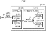
- a dental appliance manufacturing device 10 includes a controller 20 and a processing machine 30.
- Numerical control (NC) data generated in computer aided manufacturing (CAM) 40 is input to the dental appliance manufacturing device 10.
- the controller 20 controls the processing machine 30 based on the input NC data.
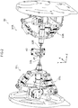
- the processing machine 30 is equipped with two cutting processing units 31L, 31R.
- the cutting processing unit 31L and the cutting processing unit 31R are disposed so as to face each other across a processing stage 42 in the middle, on which a cutting workpiece 45 (material of a dental appliance) is set up on.
- the cutting processing unit 31L also includes a cutter section 32L such as a drill for processing the cutting workpiece 45 set up on the processing stage 42 by cutting, and a drive section 33L to move the cutter section 32L.
- the drive section 33L supports the cutter section 32L such that the axial direction of the cutter section 32L is parallel to the Z axis (described in detail later).
- the drive section 33L includes an arm to move the supported cutter section 32L to a specified position within a processing machine coordinate system, and a motor to drive the arm.
- the cutting processing unit 31R similarly includes a cutter section 32R and a drive section 33R.
- the drive sections 33L, 33R are driven according to pulse signals output from a motion controller 35, described later.
- the processing machine coordinate system may be a coordinate system with three orthogonal axes (X axis, Y axis, and Z axis) having an origin at a predetermined position on the processing stage 42 (the center position thereof, for example).
- the Y axis is in the vertical direction
- the Z axis is a direction orthogonal to the Y axis and is a direction the cutting processing unit 31L and the cutting processing unit 31R face each other along
- the X axis is a horizontal direction orthogonal to both the Y axis and the Z axis.
- the processing machine 30 also includes a motion controller 35, as illustrated in Fig. 1 .
- the motion controller 35 outputs pulse signals to the drive sections 33L, 33R according to NC data output from the controller 20, described later.
- the controller 20 also receives the NC data input from CAM 40.
- Fig. 3 illustrates an example of NC data.
- the processing machine 30 of the dental appliance manufacturing device 10 includes the two cutting processing units 31L, 31R. Therefore, NC data 41L for use by the cutting processing unit 31L (referred to below as "L-”) and NC data 41R for use by the cutting processing unit 31R (referred to below as "R-”) is input from the CAM 40.
- the L-NC data 41L is data combining post-movement coordinate values (L-X, L-Y, and L-Z) of a predetermined position (for example, a tip portion) on the cutter section 32L, and a movement speed (L-speed) when moving the cutter section 32L to the post-movement coordinate values.
- the R-NC data 41R is data combining post-movement coordinate values (R-X, R-Y, and R-Z) of a predetermined position (for example, a tip portion) on the cutter section 32R, and a movement speed (R-speed) when moving the cutter section 32R to the post-movement coordinate values.
- One set of coordinate values and movement speed data is one segment's worth of data in the NC data (one line's worth of data in the example of Fig. 3 , referred to below as a "segment of NC data").
- the cutting processing units 31L, 31R are respectively controlled by the L-NC data 41L and the R-NC data 41R that each include plural segments of NC data, so as to implement a chain (series) of processes for cutting processing.
- the controller 20 functionally includes a prediction section 21 and a correction section 22.
- the prediction section 21 arranges the segments of NC data respectively contained in the input L-NC data 41L and R-NC data 41R along the time axis, and then re-divides the segments of NC data such that control times for cutting processing as indicated in segments of NC data at corresponding places in the sequence from the start of processing are the same as each other.
- the prediction section 21 compares the corresponding segments of NC data in the L-NC data 41L and the R-NC data 41R against each other, and predicts whether or not interference will occur between the cutter section 32L and the cutter section 32R at the cutting processing time indicated by that segment of NC data.
- the correction section 22 corrects at least one of the L-NC data 41L and the R-NC data 41R when the prediction section 21 has predicted that interference will occur between the cutter section 32L and the cutter section 32R, so as to avoid interference.
- the correction section 22 outputs the corrected L-NC data 41L and the R-NC data 41R to the motion controller 35.
- the controller 20 in the dental appliance manufacturing device 10 may, for example, be implemented by a computer 50 as illustrated in Fig. 4 .
- the computer 50 includes a CPU 51, a memory 52 serving as a temporary storage region, and a non-volatile storage section 53.
- the computer 50 also includes an input/output device 54, a read/write (R/W) section 55 to control reading data from a storage medium 59 and writing data to the storage medium 59, and a communications interface (I/F) 56.
- the CPU 51, the memory 52, the storage section 53, the input/output device 54, the R/W section 55, and the communications I/F 56 are connected together through a bus 57.
- the storage section 53 may be implemented by a hard disk drive (HDD), a solid state drive (SSD), flash memory, or the like.
- a control program 60 for dental appliance manufacture is stored on a storage section 53 serving as a storage medium.
- the control program 60 causes the computer 50 to function as the controller 20 of the dental appliance manufacturing device 10.
- the control program 60 includes a prediction process 61 and a correction process 62.
- the CPU 51 reads the control program 60 from the storage section 53, loads the control program 60 in the memory 52, and sequentially executes each of the processes contained in the control program 60.
- the CPU 51 operates as the prediction section 21 illustrated in Fig. 1 by executing the prediction process 61.
- the CPU 51 operates as the correction section 22 illustrated in Fig. 1 by executing the correction process 62.
- the computer 50 executing the control program 60 thereby functions as the controller 20 of the dental appliance manufacturing device 10.
- control program 60 may, for example, be implemented by a semiconductor integrated circuit, or more precisely by an application specific integrated circuit (ASIC) or the like.
- ASIC application specific integrated circuit
- profile data (3D data or the like) for a dental appliance to be manufactured is generated by computer aided design (CAD) or the like.
- L-NC data 41L and R-NC data 41R is generated by the CAM 40 based on this profile data.
- the L-NC data 41L and the R-NC data 41R may be respectively generated without consideration to interference between the cutter section 32L and the cutter section 32R during simultaneous processing.
- the controller 20 executes control processing for dental appliance manufacture as illustrated in Fig. 5 .
- the prediction section 21 receives the input L-NC data 41L and R-NC data 41R.
- the prediction section 21 arranges the plural segments ofNC data respectively included in the L-NC data 41L and the R-NC data 41R input thereto along the time axis, and then computes control times based on each of the segments of NC data. More specifically, the prediction section 21 takes a distance between a position indicated by the coordinate values included in the previous segment of NC data to a position indicated by coordinate values included in the segment of NC data currently being computed, and divides this distance by the movement speed contained in the current segment of NC data, so as to compute the control time for the current segment of NC data.
- positions indicated by the coordinate values included in segments of NC data are referred to as the "specified positions of the segments of NC data”
- the movement speeds included in the segments of NC data are referred to as the "specified movement speeds of the segments of NC data”.
- the prediction section 21 then associates segments of NC data segments of NC data having the same control time in sequence from the start of processing in the L-NC data 41L and the R-NC data 41R with each other. Moreover, when the segments ofNC data do not have a one-to-one correspondence, the prediction section 21 divides the segments of NC data so that there is the same number of segments ofNC data in the L-NC data 41L and the R-NC data 41R.
- the prediction section 21 receives the L-NC data 41L and the R-NC data 41R as illustrated at the top stage of Fig. 6 .
- the L-segment ofNC data A corresponds to the R-segments ofNC data B and C.
- the prediction section 21 therefore, as illustrated in the bottom stage of Fig. 6 , divides the segment of NC data A into segments of NC data A1 and A2 to give a two-to-two correspondence between the L-segments of NC data and the R-segments of NC data.
- the prediction section 21 generates a segment of NC data A1 including coordinate values indicating a position on the track for movement to the specified position of the segment of NC data A that will be the position arrived at when moved for the control time of the segment of NC data B at the specified movement speed of the segment of NC data A.
- the prediction section 21 employs the original segment of NC data A as a segment of NC data A2, and inserts the generated segment of NC data A1 in front of the segment of NC data A2.
- the segment of NC data A1 and the segment of NC data B, and the segment of NC data A2 and the segment of NC data C thereby correspond to each other.
- the prediction section 21 selects one segment in the sequence from the start of processing of the respective re-divided segments of the L-NC data 41L and R-NC data 41R.
- the prediction section 21 predicts whether or not interference will occur between the cutter section 32L and the cutter section 32R when the cutter sections 32L and 32R are being moved to the specified positions of the segments of NC data for the selected segment.
- the prediction section 21 is able to predict that interference will occur when the track of the cutter section 32L and the track of the cutter section 32R cross each other between the specified position of the previous segments of NC data and the specified position of the selected segments of NC data. Processing transitions to step S15 when interference is predicted to occur between the cutter section 32L and the cutter section 32R in the selected segment.
- the prediction section 21 may predict not only the occurrence of interference between the cutter sections 32L and the cutter section 32R, but also the occurrence of interference between the whole body of the cutting processing unit 31L and the whole body of the cutting processing unit 31R. In such cases, for example, the prediction section 21 identifies a space swept out by the cutting processing unit 31L when moving from the specified position of the previous segment of NC data to the specified position of the selected segment of NC data. The prediction section 21 is then able to predict the occurrence of interference when part of the cutting processing unit 31R enters this identified space while moving from the specified position of the previous segment of NC data to the specified position of the selected the segment of NC data.
- the space can be identified by preparing profile data of the cutting processing units 31L, 31R in advance, and then performing identification based on this profile data and control quantities from the NC data.
- the correction section 22 corrects at least one of the L-NC data 41L and the R-NC data 41R so as to avoid interference.
- the correction section 22 corrects the NC data so as to perform any interference avoidance control of "wait”, “retraction”, “acceleration/deceleration”, and "processing sequence change" interference avoidance control.
- a detailed description follows regarding NC data correction for each type of interference avoidance control, with reference to Fig. 7 . Note that in Fig. 7 each of the blocks appended with numbers represents one segment of NC data. Moreover, an example is described of a case in which the R-NC data 41R is corrected.
- the interference avoidance control for "wait” is control to cause the cutter section 32R to wait and not move to the position where interference with the cutter section 32L is predicted to occur.
- the correction section 22 blanks out the R-segment of NC data for the segment where interference is predicted to occur as NC data correction for "wait” interference avoidance control, as illustrated at A in Fig. 7 . Along with this action, the correction section 22 also shifts subsequent R-segments of NC data to one segment later.
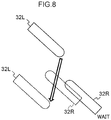
- interference is predicted to occur when the cutter sections 32L and 32R respectively move from the positions indicated by the solid lines to the positions indicated by the broken lines.
- Blanking out the R-segment ofNC data for this segment causes the cutter section 32R to wait at the specified position of the previous segment of NC data (the position indicated by the solid line) while the cutter section 32L is moving from the position indicated by the solid line to the position indicated by the broken line. Interference between the cutter section 32L and the cutter section 32R is thereby avoided.
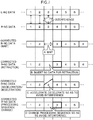
- correction of the NC data is performed by, for example as illustrated in Fig. 9 , inserting a segment of NC data to avoid interference into the segment in which interference is predicted to occur (the broken line portion in Fig. 9 ).
- blanking out is represented by the symbol "*".
- the L-segments of NC data and the corrected R-segments of NC data are then compared with each other for subsequent segments to determine whether or not interference will occur.
- segments that have been associated with each other so as to have the same control times at step S12 become shifted away from each other.
- the prediction section 21 may re-execute the processing of the step S12 for these subsequent segments.
- the L-NC data 41L and the R-NC data 41R may be respectively divided into segments so as to have the same predetermined control time as each other. In such cases, since the control times of all the segments of NC data are the same as each other, there is no need to re-associate the NC data.
- control is performed so as to retract the cutter section 32R from the position where interference with the cutter section 32L is predicted to occur.
- the correction section 22 shifts the R-segments of NC data for segments subsequent to the segment in which interference is predicted to occur later by one segment, as illustrated at B in Fig. 7 .
- the correction section 22 also inserts a segment of NC data to retract the cutter section 32R from the position where interference is predicted to occur by insertion into the segment where interference is predicted to occur.
- interference is predicted to occur even if the cutter section 32R is caused to wait at the position indicated by the solid line in a case in which the cutter sections 32L and 32R are respectively moved from the positions indicated by the solid lines to the positions indicated by the broken lines.
- the correction section 22 accordingly generates a segment of NC data to move the cutter section 32R to a position where interference will not occur (the position indicated by the single dot broken line), and also moves the cutter section 32R back to its original position (the position indicated by the solid line) after the cutter section 32L has passed.
- the correction section 22 inserts the generated segment of NC data for retraction into the appropriate location in the R-NC data 41R.
- coordinate values indicating a retraction position may be added into the R-segment of NC data for the segment to be corrected.
- An appropriate movement speed is then associated with these coordinate values, and the movement speed associated with the original coordinate values is also corrected.
- the movement speed to associate with each coordinate value is determined such that the control time of each segment is the same as the original control time.
- the corrected segment of NC data may be divided at the respective portions of the coordinate values. In such cases the corresponding L-segment of NC data is also divided so as to have the same control times.
- a segment of NC data (3-1) to move to the retraction position, and a segment of NC data (3-2) to return from the retraction position to the original position are inserted. While doing so, the segment of NC data for segment 3 of the L-NC data 41L is also divided into a segment of NC data (3-1) and a segment of NC data (3-2).
- configuration may be made such that after the cutter section 32R has been retracted to the retraction position, the segment of NC data for the next segment may, instead of returning the cutter section 32R to the original position, move the cutter section 32R to the position indicated by the NC data for this next segment.
- the specified movement speed of the next segment of NC data is corrected to correspond to the control time for the next segment.
- the "acceleration/deceleration” interference avoidance control is control to accelerate or decelerate the movement speed of the cutter section 32R so as to avoid interference with the cutter section 32L.
- the correction section 22 corrects so that the specified movement speed of the R-segment of NC data for the segment in which interference is predicted to occur changes within the segment, as illustrated at C in Fig. 7 .
- the cutter section 32R is decelerated until the cutter section 32L has passed so that the cutter section 32R does not arrive at the position of interference.
- the cutter section 32R is then accelerated so as to move to the specified position after the cutter section 32L has passed.
- the cutter section 32R is accelerated so as to move away from the position of interference before the cutter section 32L passes. Then after having moved away from the position of interference, the cutter section 32R is decelerated as it is being moved to the specified position.
- acceleration/deceleration interference avoidance control for example, plural coordinate values may be given to the R-segment of NC data in the segment to be corrected. Then faster movement speeds than the original movement speeds are associated with the coordinate values corresponding to locations of acceleration, and slower movement speeds than the original movement speeds are associated with the coordinate values corresponding to locations of deceleration. Note that the movement speeds to be associated with each of the coordinate positions are determined such that the control times of such segments are the same as the original control times.
- the "processing sequence change” interference avoidance control is control to avoid interference with the cutter section 32L by switching the sequence of processes in processing by the cutter section 32R.
- the correction section 22 changes the sequence of segments of NC data where interference is predicted to occur for NC data of other segments where interference is not predicted to occur, as illustrated at D in Fig. 7 .
- interference with the cutter section 32L occurs in cases in which the cutter section 32R is moved from the specified position of the R-segment of NC data 2 (position indicated by the solid line) to the specified position of the R-segment of NC data 3 (position indicated by the broken line).
- interference with the cutter section 32L does not occur in cases in which the cutter section 32R is moved from the specified position of the R-segment of NC data 2 (position indicated by the solid line) to the specified position of the R-segment of NC data 4 (position indicated by the single dot broken line). In such cases, interference is avoided by switching the R-segment of NC data 3 with the R-segment of NC data 4.
- the correction section 22 corrects the specified movement speeds of the segments of NC data such that the control times of the segments after switching are the same control times as those of the L-segments of NC data. Moreover, since the movement distance of the next segment changes when segments are switched and the processing sequence is changed, the movement speeds are also corrected to match the control times of each of the respective segments. Moreover, after the segments have been switched, re-dividing of segments at step S12 may be executed again.
- the L-NC data 41 may be corrected, or both types of NC data may be corrected.
- correcting both sets of NC data enables interference avoidance control to be performed smoothly.
- step S14 When the prediction section 21 has not predicted at step S14 that interference will occur, processing transitions to step S16, skipping the processing of step S15.
- step S16 the correction section 22 determines whether or not all of the segments of the NC data have already been selected at step S13. Processing returns to step S13 when there are still some segments present that have not yet been selected, the prediction section 21 selects the next segment, and the processing of steps S14 and S15 is repeated. However, when selection of all segments has already been completed, processing transitions to step S17, the correction section 22 outputs the corrected L-NC data 41L and R-NC data 41R to the motion controller 35, and ends the dental appliance manufacturing control processing.
- the motion controller 35 On receipt of the corrected L-NC data 41L and R-NC data 41R, the motion controller 35 outputs a pulse signal based on the received L-NC data 41L to the drive section 33L, and outputs a pulse signal based on the received R-NC data 41R to the drive section 33R.
- the drive sections 33L, 33R are thereby driven by quantities based on the pulse signals, and the cutter sections 32L and 32R are moved to the positions specified by the NC data. Cutting processing is accordingly performed on the cutting workpiece 45 set up on the processing stage 42.
- the dental appliance manufacturing device 10 corrects NC data, when plural cutting processing units are being used during simultaneous processing, so as to control at least one of the cutting processing units such that the cutting processing units do not move to positions where they would interfere with each other. This enables interference avoidance to be performed efficiently when plural processing mechanisms are being used during simultaneous processing.
- the dental appliance manufacturing device 10 arranges the segments of NC data included in the L-NC data 41L and the R-NC data 41R along the time axis, and re-divides segments so that the control times are the same for cutting processing represented by segments of NC data corresponding to the same place in the sequence from the start of processing. Doing so enables the occurrence of interference between moving bodies, i.e., interference between the cutter section 32L and the cutter section 32R, to be easily predicted. Moreover, when respectively generating the L-NC data 41L and R-NC data 41R, there is no need to consider interference between the cutter section 32L and the cutter section 32R as controlled based on the L-NC data 41L and R-NC data 41R. This enables the computation load for NC data generation to be suppressed. Moreover, utilizing the independently generated L- and R-NC data enables interference avoidance control to be performed efficiently.
- the occurrence of interference is predicted for all of segments of the L-NC data 41L, 41R that contain the plural segments of NC data representing chains of processes for cutting processing, and the NC data is corrected in cases in which interference is predicted to occur. Cases have been described in which cutting processing chains are subsequently performed based on this corrected NC data; however, there is no limitation thereto. Configuration may be made such that the prediction of interference occurrence and the correction of NC data when interference would occur are executed in real-time during cutting processing.
- the controller 20 executes the dental appliance manufacturing control processing illustrated in Fig. 14 .
- the same step number is appended to processing that is the same as the dental appliance manufacturing control processing illustrated in Fig. 5 , and detailed description thereof will be omitted.
- step S11 to S15 the prediction section 21 and the correction section 22 predict the occurrence of interference for a selected segment and perform NC data correction when interference will occur. Then at the next step S117, the correction section 22 outputs corrected L- and R-segments of NC data for the selected segment to the motion controller 35.
- the motion controller 35 outputs pulse signals based on the received segments of NC data to the drive sections 33L, 33R.
- the drive sections 33L, 33R are driven by the amount of these pulse signals, and move the cutter sections 32L, 32R to the specified coordinate positions in the selected segment of NC data.
- the motion controller 35 may be configured so as to immediately output pulse signals based on the received NC data to the drive sections 33L, 33R.
- configuration may be made such that the motion controller 35 buffers a predetermined number of segments' worth of the received segments of NC data, and the predetermined number of segments' worth of time lag is introduced from receipt of the NC data to output of the pulse signal.
- the correction section 22 determines whether or not processing for all segments has already been completed. Processing returns to step S13 when there are still some segments present that have not yet been selected. This enables the prediction of interference occurrence and the correction of NC data when interference will occur to be executed in real-time during cutting processing.
- a dental appliance manufacturing device 210 includes a controller 220 and a processing machine 230.
- the processing machine 230 includes motion controllers 35L, 35R instead of the motion controller 35 according to the first exemplary embodiment.
- the motion controller 35L outputs a pulse signal based on L-NC data 41L output from the controller 220 to a drive section 33L of a cutting processing unit 31L.
- the motion controller 35R outputs a pulse signal based on R-NC data 41L output from the controller 20 to a drive section 33R of a cutting processing unit 31R.
- the controller 220 functionally includes a prediction section 21, a correction section 22, and an adjustment section 23.
- the cutting processing units 31L, 31R are each controlled based on pulse signals output from the respective corresponding motion controllers 35L, 35R. Therefore, a misalignment may arise in actual control times even when the L-NC data 41L and R-NC data 41R are divided and associated with each other such that each segment has the same control time.
- the adjustment section 23 compares a state of progress of control of the cutting processing unit 31L based on the L-NC data 41L against a state of progress of control of the cutting processing unit 31R based on the R-NC data 41R, and checks whether or not the two controls are in synchronization with each other.
- the adjustment section 23 outputs an adjustment signal to adjust a control timing to at least one of the motion controller 35L and 35R when the two controls are not in synchronization with each other. Adjustment of the control timing is not limited to being performed by the adjustment section 23.
- the motion controllers 35L and 35R may perform adjustment of the control timing with reference to a common standard time or the like for the motion controllers 35L and 35R.
- the controller 220 of the dental appliance manufacturing device 210 may, for example, be implemented by the computer 50 illustrated in Fig. 4 .
- a dental appliance manufacturing control program 260 that causes the computer 50 to function as the controller 220 of the dental appliance manufacturing device 210 is stored in the storage section 53 of the computer 50.
- the control program 260 includes a prediction process 61, a correction process 62, and an adjustment process 63.
- a CPU 51 reads the control program 260 from a storage section 53, loads the control program 260 into memory 52, and then sequentially executes each of the processes included in the control program 260.
- the CPU 51 operates as the adjustment section 23 illustrated in Fig. 15 by executing the adjustment process 63.
- the other processes are similar to the processes of the control program 60 according to the first exemplary embodiment.
- the computer 50 executing the control program 260 accordingly functions as the controller 220 of the dental appliance manufacturing device 210.
- control program 260 may, for example, be implemented by a semiconductor integrated circuit, or more precisely by an ASIC or the like.
- the adjustment processing illustrated in Fig. 16 is executed in parallel with control processing for dental appliance manufacture similar to that of the first exemplary embodiment ( Fig. 5 ).
- the adjustment processing is repeatedly executed at predetermined timings.
- the predetermined timings may, for example, be a periodic timing, a timing of each boundary between predetermined segments, a timing specified by a user, or the like.
- the adjustment section 23 acquires a state of progress of control of the cutting processing unit 31L based on the L-NC data 41L and a state of progress of control of the cutting processing unit 31R based on the R-NC data 41R.
- the adjustment section 23 acquires as the state of progress which portions of the pulse signals currently being output from the motion controllers 35L, 35R correspond to the L-NC data 41L and the R-NC data 41R.
- the adjustment section 23 compares the L-state of progress and the R-state of progress acquired at step S21, and determines whether or not the control of the cutting processing unit 31L and the control of the cutting processing unit 31R are in synchronization with each other.
- the adjustment processing is ended when the controls are in synchronization with each other.
- step S23 processing transitions to step S23 when they are not in synchronization with each other, and the adjustment section 23 outputs an adjustment signal to adjust the control timing of at least one of the motion controller 35L and 35R.
- the adjustment section 23 may, for example, output a signal to the motion controllers 35L, 35R to synchronize timings for output of pulse signals based on the segments of NC data for the next segments.
- the adjustment section 23 may, for example, output a signal to stop the output of pulse signals to the motion controller 35L or 35R that corresponds to the cutting processing unit 31L or 31R in the most advanced state of progress, with the stop signal being output for the amount of misalignment time of the timings. After the adjustment section 23 has output the adjustment signal the adjustment processing is ended.
- the dental appliance manufacturing device 210 adjusts so that controls of the cutting processing unit 31L and the cutting processing unit 31R are in synchronization with each other even in cases in which the cutting processing units 31L, 31R are each driven by different respective motion controllers 35L, 35R.
- the appropriate associations are thereby maintained between each segment of the L-segments of NC data and the R-segments of NC data that have been divided so that the control times are the same.
- a dental appliance manufacturing device 310 includes a controller 320 and a processing machine 330.
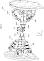
- the processing machine 330 is equipped with two cutting processing units 331L, 331R.
- the cutting processing unit 331L and the cutting processing unit 331R in the third exemplary embodiment are also disposed so as to face each other across a processing stage 42 in the middle.
- the cutting processing unit 331L includes two cutter sections 32L1, 32L2, and a drive section 33L to move the two cutter sections 32L1, 32L2 as a single unit.
- the cutter section 32L1 and the cutter section 32L2 are, for example, different types of cutter section, such as a drill for rough-cutting and a drill for finishing, and have different sizes as represented by at least one of length and diameter of drill bit.
- the cutter section 32L1 is larger in size than the cutter section 32L2.
- the cutter section 32L1 and the cutter section 32L2 are supported by an arm as a single body such that their axial directions are parallel to the Z axis.
- the cutting processing unit 331R also includes two cutter sections 32R3, 32R4 and a drive section 33L.
- the cutter section 32R3 is larger in size than the cutter section 32R4.
- the controller 320 receives NC data input from a CAM 40.
- NC data of the third exemplary embodiment is illustrated in Fig. 18 .
- Each of the segments of NC data in L-NC data 341L contains a coordinate position and a movement speed, as well as information to identify whether the cutter section 32L1 or the cutter section 32L2 is the target cutter section (L-target cutter section) for control by each of the segments of NC data.
- each segment of NC data of R-NC data 341R contains a coordinate position and a movement speed, as well as information to identify whether the cutter section 32R3 or the cutter section 32R4 is the target cutter section (R-target cutter section) for control by each of the segments of NC data.
- the controller 320 functionally includes a prediction section 321 and a correction section 322.
- the prediction section 321 re-divides the segments of NC data so that the control times are the same.
- the prediction section 321 compares corresponding segments of NC data in the L-NC data 41L and in the R-NC data 41R, and predicts whether or not cutter section interference will occur during cutting processing as represented by the segments of NC data.
- the prediction section 321 not only predicts interference between cutter sections that are performing cutting processing, but also predicts the occurrence of interference with cutter sections not performing cutting processing.
- the prediction section 321 computes a position of cutter sections not performing cutting processing based on specified positions in segment NC data for the cutter sections performing cutting processing, and on mounting positional relationships between the cutter sections.
- the prediction section 321 predicts whether or not interference between the cutter section 32L1 and the cutter section 32R3 will occur, similarly to in the first exemplary embodiment.
- the prediction section 321 also predicts interference between the cutter section 32L1 and the cutter section 32R4, and interference between the cutter section 32L2 and the cutter section 32R4.
- the correction section 322 corrects the NC data so that interference avoidance control is performed when the prediction section 321 has predicted interference will occur. When doing so, the correction section 322 corrects the NC data to perform interference avoidance control such that interference does not occur between the cutter sections 32L1 and 32L2, nor between the cutter sections 32R3 and 32R4.
- the correction section 322 accordingly corrects the NC data to keep the larger sized cutter sections a predetermined distance apart when performing interference avoidance control.
- the controller 320 of the dental appliance manufacturing device 310 may, for example, be implemented by the computer 50 illustrated in Fig. 4 .
- a dental appliance manufacturing control program 360 to cause the computer 50 to function as the controller 320 of the dental appliance manufacturing device 310 is stored in the storage section 53 of the computer 50.
- the control program 360 includes a prediction process 361 and a correction process 362.
- the CPU 51 reads the control program 360 from the storage section 53, loads the control program 360 in the memory 52, and sequentially executes each of the processes included in the control program 360.
- the CPU 51 operates as the prediction section 321 illustrated in Fig. 1 by executing the prediction process 361.
- the CPU 51 operates as the correction section 322 illustrated in Fig. 1 by executing the correction process 362.
- the computer 50 executing the control program 360 thereby functions as the controller 320 of the dental appliance manufacturing device 310.
- the functionality implemented by the dental appliance manufacturing control program 360 may, for example, be implemented by a semiconductor integrated circuit, or more precisely by an ASIC or the like.
- the operation of the dental appliance manufacturing device 310 according to the third exemplary embodiment only differs from that of the dental appliance manufacturing control processing illustrated in Fig. 5 in the point that interference of all of the cutter sections is considered in steps S14 and S15 thereof, and so description will be omitted thereof.
- the dental appliance manufacturing device 310 is able to efficiently perform interference avoidance during simultaneous processing, even for cases in which the cutting processing units 31L, 31R have plural cutter sections.
- respective motion controllers 35L, 35R may also be provided so as to correspond to the cutting processing units 31L, 31R.
- an adjustment section 23 similar to that of the second exemplary embodiment is provided in the controller 320.
- the cutting processing unit 31L and the cutting processing unit 31R are disposed so as to face each other across a processing stage 42 in the middle, there is no limitation thereto.
- the cutting processing unit 31L may be disposed so as to perform processing diagonally from the upper left of a cutting workpiece 45 set on a processing stage 42
- the cutting processing unit 31R may be disposed at the so as to perform processing diagonally from the upper right thereof.
- control programs 60, 260, 360 are pre-stored (installed) on the storage section 53, there is no limitation thereto.
- the control program according to the present invention may be provided in a format recorded on a recording medium such as a CD-ROM, DVD-ROM, USB memory or the like.
Landscapes
- Engineering & Computer Science (AREA)
- Human Computer Interaction (AREA)
- Manufacturing & Machinery (AREA)
- Physics & Mathematics (AREA)
- General Physics & Mathematics (AREA)
- Automation & Control Theory (AREA)
- Numerical Control (AREA)
Abstract
Description
- The present invention relates to a dental appliance manufacturing device, a dental appliance manufacturing method, and a dental appliance manufacturing program.
- For example, when manufacturing a processed article such as a dental appliance, a manufacturing device equipped with a processing mechanism is employed to perform cutting processing or the like on stock material for the processed article. Processing is performed on a material by controlling the position of a processing head along three orthogonal axes using numerical control, for example.
- Various methods are adopted in such a manufacturing device to reduce the processing time, such as processing two faces by flipping the material over, or by disposing a pair of processing mechanisms so as to face each other across the material in the middle, and performing simultaneous processing.
- There is also a proposal for a numerically controlled device that avoids collisions with obstructions, such as materials, tools, tailstocks, and the like that lie in the movable range of a machine tool when an operator is performing any operation during manual operation of a machine tool. In such devices, functions are generated to control axial movements of moving bodies in the machine tool according to manual axial movement operations. Profile data of a moving body and profile data of any obstructions that might possibly interfere with the moving bodies are stored. A check is then made as to whether or not there is going to be any interference with the profile data of the obstructions, by moving the profile data of the moving body in the movement direction of the axial movement operation prior to starting the generation of a function according to the manual axial movement operation. Then, in cases in which interference would occur, an axial movement stop position is calculated that is a desired distance away from the position of interference in the opposite direction to the movement direction, and a function is generated so as to stop the moving body at the movement stop position.
-
- Patent Document 1: Japanese Patent Application Laid-Open (
JP-A) No. 2006-059187 - Patent Document 2:
JP-A No. S63-266505 - When performing simultaneous processing using plural processing mechanisms as described above, there is a need to perform control such that respective processing mechanisms do not interfere. Although conventional technology exists to avoid interference between a processing mechanism and an obstruction lying within the movable range of the processing mechanism, in such cases the obstruction is a stationary object. This technology is accordingly not applicable to avoiding interference between processing mechanisms that are moving.
- An object of an aspect of the present invention is to suppress interference between plural processing mechanisms in a dental appliance manufacturing device.
- An aspect of the present invention is a dental appliance manufacturing device including a first cutting processing means, a second cutting processing means, and a control means that controls positions of the first cutting processing means and the second cutting processing means. The control means is capable of causing cutter sections of the first cutting processing means and of the second cutting processing means to contact a cutting workpiece and execute cutting on the cutting workpiece from two sides of the cutting workpiece. The control means also controls such that the cutter section of the second cutting processing means does not move to a position of interference while the cutter section of the first cutting processing means is contacting the cutting workpiece.
- The aspect has the effect of enabling interference between plural processing mechanisms of a dental appliance manufacturing device to be suppressed.
-
-
Fig. 1 is a block diagram illustrating an outline configuration of a dental appliance manufacturing device according to first and third exemplary embodiments. -
Fig. 2 is a perspective view of the external appearance a processing machine of first and second embodiments. -
Fig. 3 is a diagram illustrating an example of NC data in the first and second embodiments. -
Fig. 4 is a block diagram illustrating a schematic configuration of a computer that functions as a controller of the dental appliance manufacturing device according to the first to third exemplary embodiments. -
Fig. 5 is a flowchart illustrating an example of control processing in dental appliance manufacture. -
Fig. 6 is a diagram to explain dividing of NC data. -
Fig. 7 is a diagram to explain interference avoidance control. -
Fig. 8 is a diagram to explain wait interference avoidance control. -
Fig. 9 is a diagram illustrating an example of correction of NC data. -
Fig. 10 is a diagram to explain retraction interference avoidance control. -
Fig. 11 is a diagram to explain acceleration/deceleration interference avoidance control. -
Fig. 12 is a diagram to explain acceleration/deceleration interference avoidance control. -
Fig. 13 is a diagram to explain processing sequence change interference avoidance control. -
Fig. 14 is a flowchart illustrating another example of control processing in dental appliance manufacture. -
Fig. 15 is a block diagram illustrating an outline configuration of a dental appliance manufacturing device according to the second exemplary embodiment. -
Fig. 16 is a flowchart illustrating an example of adjustment processing. -
Fig. 17 is a perspective view of the external appearance of a processing machine in the third exemplary embodiment. -
Fig. 18 is a diagram illustrating an example of NC data in the third exemplary embodiment. -
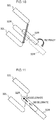
Fig. 19 is a diagram to explain an occurrence of interference due to the size of a cutter section. - Detailed description follows regarding an example of an exemplary embodiment according to the present invention, with reference to the drawings.
- As illustrated in
Fig. 1 , a dentalappliance manufacturing device 10 according to a first exemplary embodiment includes acontroller 20 and aprocessing machine 30. Numerical control (NC) data generated in computer aided manufacturing (CAM) 40 is input to the dentalappliance manufacturing device 10. Thecontroller 20 controls theprocessing machine 30 based on the input NC data. - As illustrated in
Fig. 2 , theprocessing machine 30 is equipped with twocutting processing units cutting processing unit 31L and thecutting processing unit 31R are disposed so as to face each other across aprocessing stage 42 in the middle, on which a cutting workpiece 45 (material of a dental appliance) is set up on. Thecutting processing unit 31L also includes acutter section 32L such as a drill for processing thecutting workpiece 45 set up on theprocessing stage 42 by cutting, and adrive section 33L to move thecutter section 32L. For example, thedrive section 33L supports thecutter section 32L such that the axial direction of thecutter section 32L is parallel to the Z axis (described in detail later). Thedrive section 33L includes an arm to move the supportedcutter section 32L to a specified position within a processing machine coordinate system, and a motor to drive the arm. Thecutting processing unit 31R similarly includes acutter section 32R and adrive section 33R. Thedrive sections motion controller 35, described later. - Note that the processing machine coordinate system may be a coordinate system with three orthogonal axes (X axis, Y axis, and Z axis) having an origin at a predetermined position on the processing stage 42 (the center position thereof, for example). Note that in the present exemplary embodiment, as illustrated in
Fig. 2 , the Y axis is in the vertical direction, the Z axis is a direction orthogonal to the Y axis and is a direction thecutting processing unit 31L and thecutting processing unit 31R face each other along, and the X axis is a horizontal direction orthogonal to both the Y axis and the Z axis. - The
processing machine 30 also includes amotion controller 35, as illustrated inFig. 1 . Themotion controller 35 outputs pulse signals to thedrive sections controller 20, described later. - The
controller 20 also receives the NC data input fromCAM 40.Fig. 3 illustrates an example of NC data. As described above, the processingmachine 30 of the dentalappliance manufacturing device 10 includes the two cuttingprocessing units NC data 41L for use by the cuttingprocessing unit 31L (referred to below as "L-") andNC data 41R for use by the cuttingprocessing unit 31R (referred to below as "R-") is input from theCAM 40. - The L-
NC data 41L is data combining post-movement coordinate values (L-X, L-Y, and L-Z) of a predetermined position (for example, a tip portion) on thecutter section 32L, and a movement speed (L-speed) when moving thecutter section 32L to the post-movement coordinate values. Similarly, the R-NC data 41R is data combining post-movement coordinate values (R-X, R-Y, and R-Z) of a predetermined position (for example, a tip portion) on thecutter section 32R, and a movement speed (R-speed) when moving thecutter section 32R to the post-movement coordinate values. One set of coordinate values and movement speed data is one segment's worth of data in the NC data (one line's worth of data in the example ofFig. 3 , referred to below as a "segment of NC data"). The cuttingprocessing units NC data 41L and the R-NC data 41R that each include plural segments of NC data, so as to implement a chain (series) of processes for cutting processing. - Moreover, as illustrated in
Fig. 1 , thecontroller 20 functionally includes aprediction section 21 and acorrection section 22. - The
prediction section 21 arranges the segments of NC data respectively contained in the input L-NC data 41L and R-NC data 41R along the time axis, and then re-divides the segments of NC data such that control times for cutting processing as indicated in segments of NC data at corresponding places in the sequence from the start of processing are the same as each other. Theprediction section 21 then compares the corresponding segments of NC data in the L-NC data 41L and the R-NC data 41R against each other, and predicts whether or not interference will occur between thecutter section 32L and thecutter section 32R at the cutting processing time indicated by that segment of NC data. - The
correction section 22 corrects at least one of the L-NC data 41L and the R-NC data 41R when theprediction section 21 has predicted that interference will occur between thecutter section 32L and thecutter section 32R, so as to avoid interference. Thecorrection section 22 outputs the corrected L-NC data 41L and the R-NC data 41R to themotion controller 35. - The
controller 20 in the dentalappliance manufacturing device 10 may, for example, be implemented by acomputer 50 as illustrated inFig. 4 . Thecomputer 50 includes aCPU 51, amemory 52 serving as a temporary storage region, and anon-volatile storage section 53. Thecomputer 50 also includes an input/output device 54, a read/write (R/W)section 55 to control reading data from astorage medium 59 and writing data to thestorage medium 59, and a communications interface (I/F) 56. TheCPU 51, thememory 52, thestorage section 53, the input/output device 54, the R/W section 55, and the communications I/F 56 are connected together through abus 57. - The
storage section 53 may be implemented by a hard disk drive (HDD), a solid state drive (SSD), flash memory, or the like. A control program 60 for dental appliance manufacture is stored on astorage section 53 serving as a storage medium. The control program 60 causes thecomputer 50 to function as thecontroller 20 of the dentalappliance manufacturing device 10. The control program 60 includes aprediction process 61 and acorrection process 62. - The
CPU 51 reads the control program 60 from thestorage section 53, loads the control program 60 in thememory 52, and sequentially executes each of the processes contained in the control program 60. TheCPU 51 operates as theprediction section 21 illustrated inFig. 1 by executing theprediction process 61. TheCPU 51 operates as thecorrection section 22 illustrated inFig. 1 by executing thecorrection process 62. Thecomputer 50 executing the control program 60 thereby functions as thecontroller 20 of the dentalappliance manufacturing device 10. - Note that the functions implemented by the control program 60 may, for example, be implemented by a semiconductor integrated circuit, or more precisely by an application specific integrated circuit (ASIC) or the like.
- Next, description follows regarding operation of the dental
appliance manufacturing device 10 according to the first exemplary embodiment. - First, profile data (3D data or the like) for a dental appliance to be manufactured is generated by computer aided design (CAD) or the like. Then L-
NC data 41L and R-NC data 41R is generated by theCAM 40 based on this profile data. At this stage, the L-NC data 41L and the R-NC data 41R may be respectively generated without consideration to interference between thecutter section 32L and thecutter section 32R during simultaneous processing. When the L-NC data 41L and the R-NC data 41R generated by theCAM 40 has been input to the dentalappliance manufacturing device 10, thecontroller 20 executes control processing for dental appliance manufacture as illustrated inFig. 5 . - At step S11 of the dental appliance manufacturing control processing illustrated in
Fig. 5 , theprediction section 21 receives the input L-NC data 41L and R-NC data 41R. - Next, at step S12, the
prediction section 21 arranges the plural segments ofNC data respectively included in the L-NC data 41L and the R-NC data 41R input thereto along the time axis, and then computes control times based on each of the segments of NC data. More specifically, theprediction section 21 takes a distance between a position indicated by the coordinate values included in the previous segment of NC data to a position indicated by coordinate values included in the segment of NC data currently being computed, and divides this distance by the movement speed contained in the current segment of NC data, so as to compute the control time for the current segment of NC data. In the following, positions indicated by the coordinate values included in segments of NC data are referred to as the "specified positions of the segments of NC data", and the movement speeds included in the segments of NC data are referred to as the "specified movement speeds of the segments of NC data". - The
prediction section 21 then associates segments of NC data segments of NC data having the same control time in sequence from the start of processing in the L-NC data 41L and the R-NC data 41R with each other. Moreover, when the segments ofNC data do not have a one-to-one correspondence, theprediction section 21 divides the segments of NC data so that there is the same number of segments ofNC data in the L-NC data 41L and the R-NC data 41R. - Take, for example, a case in which the
prediction section 21 receives the L-NC data 41L and the R-NC data 41R as illustrated at the top stage ofFig. 6 . The L-segment ofNC data A corresponds to the R-segments ofNC data B and C. In such cases, there is a one-to-two correspondence of the L-segments of NC data with the R-segments of NC data. Theprediction section 21 therefore, as illustrated in the bottom stage ofFig. 6 , divides the segment of NC data A into segments of NC data A1 and A2 to give a two-to-two correspondence between the L-segments of NC data and the R-segments of NC data. More specifically, theprediction section 21 generates a segment of NC data A1 including coordinate values indicating a position on the track for movement to the specified position of the segment of NC data A that will be the position arrived at when moved for the control time of the segment of NC data B at the specified movement speed of the segment of NC data A. Theprediction section 21 employs the original segment of NC data A as a segment of NC data A2, and inserts the generated segment of NC data A1 in front of the segment of NC data A2. The segment of NC data A1 and the segment of NC data B, and the segment of NC data A2 and the segment of NC data C, thereby correspond to each other. - Then at the next step S13, the
prediction section 21 selects one segment in the sequence from the start of processing of the respective re-divided segments of the L-NC data 41L and R-NC data 41R. - Then at the next step S14, the
prediction section 21 predicts whether or not interference will occur between thecutter section 32L and thecutter section 32R when thecutter sections prediction section 21 is able to predict that interference will occur when the track of thecutter section 32L and the track of thecutter section 32R cross each other between the specified position of the previous segments of NC data and the specified position of the selected segments of NC data. Processing transitions to step S15 when interference is predicted to occur between thecutter section 32L and thecutter section 32R in the selected segment. - Note that the
prediction section 21 may predict not only the occurrence of interference between thecutter sections 32L and thecutter section 32R, but also the occurrence of interference between the whole body of the cuttingprocessing unit 31L and the whole body of the cuttingprocessing unit 31R. In such cases, for example, theprediction section 21 identifies a space swept out by the cuttingprocessing unit 31L when moving from the specified position of the previous segment of NC data to the specified position of the selected segment of NC data. Theprediction section 21 is then able to predict the occurrence of interference when part of the cuttingprocessing unit 31R enters this identified space while moving from the specified position of the previous segment of NC data to the specified position of the selected the segment of NC data. The space can be identified by preparing profile data of the cuttingprocessing units - At step S15, the
correction section 22 corrects at least one of the L-NC data 41L and the R-NC data 41R so as to avoid interference. In the present exemplary embodiment, thecorrection section 22 corrects the NC data so as to perform any interference avoidance control of "wait", "retraction", "acceleration/deceleration", and "processing sequence change" interference avoidance control. A detailed description follows regarding NC data correction for each type of interference avoidance control, with reference toFig. 7 . Note that inFig. 7 each of the blocks appended with numbers represents one segment of NC data. Moreover, an example is described of a case in which the R-NC data 41R is corrected. - The interference avoidance control for "wait" is control to cause the
cutter section 32R to wait and not move to the position where interference with thecutter section 32L is predicted to occur. Thecorrection section 22 blanks out the R-segment of NC data for the segment where interference is predicted to occur as NC data correction for "wait" interference avoidance control, as illustrated at A inFig. 7 . Along with this action, thecorrection section 22 also shifts subsequent R-segments of NC data to one segment later. - For example, as illustrated in
Fig. 8 , interference is predicted to occur when thecutter sections cutter section 32R to wait at the specified position of the previous segment of NC data (the position indicated by the solid line) while thecutter section 32L is moving from the position indicated by the solid line to the position indicated by the broken line. Interference between thecutter section 32L and thecutter section 32R is thereby avoided. - Specifically, correction of the NC data is performed by, for example as illustrated in
Fig. 9 , inserting a segment of NC data to avoid interference into the segment in which interference is predicted to occur (the broken line portion inFig. 9 ). In the example inFig. 9 , blanking out is represented by the symbol "*". The L-segments of NC data and the corrected R-segments of NC data are then compared with each other for subsequent segments to determine whether or not interference will occur. In the corrected R-segments ofNC data 41R, due to the insertion of the NC data for interference avoidance, segments that have been associated with each other so as to have the same control times at step S12 become shifted away from each other. Therefore, theprediction section 21 may re-execute the processing of the step S12 for these subsequent segments. Alternatively, at step S12 the L-NC data 41L and the R-NC data 41R may be respectively divided into segments so as to have the same predetermined control time as each other. In such cases, since the control times of all the segments of NC data are the same as each other, there is no need to re-associate the NC data. - In "retraction" interference avoidance control, control is performed so as to retract the
cutter section 32R from the position where interference with thecutter section 32L is predicted to occur. As the NC data correction for "retraction" interference avoidance control, thecorrection section 22 shifts the R-segments of NC data for segments subsequent to the segment in which interference is predicted to occur later by one segment, as illustrated at B inFig. 7 . Thecorrection section 22 also inserts a segment of NC data to retract thecutter section 32R from the position where interference is predicted to occur by insertion into the segment where interference is predicted to occur. - For example, as illustrated in
Fig. 10 , interference is predicted to occur even if thecutter section 32R is caused to wait at the position indicated by the solid line in a case in which thecutter sections correction section 22 accordingly generates a segment of NC data to move thecutter section 32R to a position where interference will not occur (the position indicated by the single dot broken line), and also moves thecutter section 32R back to its original position (the position indicated by the solid line) after thecutter section 32L has passed. Thecorrection section 22 inserts the generated segment of NC data for retraction into the appropriate location in the R-NC data 41R. - In order to implement such "retraction" interference avoidance control, for example, coordinate values indicating a retraction position may be added into the R-segment of NC data for the segment to be corrected. An appropriate movement speed is then associated with these coordinate values, and the movement speed associated with the original coordinate values is also corrected. Note that the movement speed to associate with each coordinate value is determined such that the control time of each segment is the same as the original control time. Alternatively, since the corrected segment of NC data contain plural coordinate values, the corrected segment of NC data may be divided at the respective portions of the coordinate values. In such cases the corresponding L-segment of NC data is also divided so as to have the same control times.
- More specifically, for example, in cases in which the R-segment of NC data for retraction is inserted at
segment 3 to cause retraction, as illustrated inFig. 7 , a segment of NC data (3-1) to move to the retraction position, and a segment of NC data (3-2) to return from the retraction position to the original position, are inserted. While doing so, the segment of NC data forsegment 3 of the L-NC data 41L is also divided into a segment of NC data (3-1) and a segment of NC data (3-2). - Note that configuration may be made such that after the
cutter section 32R has been retracted to the retraction position, the segment of NC data for the next segment may, instead of returning thecutter section 32R to the original position, move thecutter section 32R to the position indicated by the NC data for this next segment. In such cases, due to changing the movement distance of thecutter section 32R in the next segment, the specified movement speed of the next segment of NC data is corrected to correspond to the control time for the next segment. - The "acceleration/deceleration" interference avoidance control is control to accelerate or decelerate the movement speed of the
cutter section 32R so as to avoid interference with thecutter section 32L. As NC data correction for "acceleration/deceleration" interference avoidance control, thecorrection section 22 corrects so that the specified movement speed of the R-segment of NC data for the segment in which interference is predicted to occur changes within the segment, as illustrated at C inFig. 7 . For example, as illustrated inFig. 11 , thecutter section 32R is decelerated until thecutter section 32L has passed so that thecutter section 32R does not arrive at the position of interference. Thecutter section 32R is then accelerated so as to move to the specified position after thecutter section 32L has passed. Alternatively, as illustrated inFig. 12 , thecutter section 32R is accelerated so as to move away from the position of interference before thecutter section 32L passes. Then after having moved away from the position of interference, thecutter section 32R is decelerated as it is being moved to the specified position. In order to implement such acceleration/deceleration interference avoidance control, for example, plural coordinate values may be given to the R-segment of NC data in the segment to be corrected. Then faster movement speeds than the original movement speeds are associated with the coordinate values corresponding to locations of acceleration, and slower movement speeds than the original movement speeds are associated with the coordinate values corresponding to locations of deceleration. Note that the movement speeds to be associated with each of the coordinate positions are determined such that the control times of such segments are the same as the original control times. - The "processing sequence change" interference avoidance control is control to avoid interference with the
cutter section 32L by switching the sequence of processes in processing by thecutter section 32R. As NC data correction for "processing sequence change" interference avoidance control, thecorrection section 22 changes the sequence of segments of NC data where interference is predicted to occur for NC data of other segments where interference is not predicted to occur, as illustrated at D inFig. 7 . - For example, as illustrated in
Fig. 13 , interference with thecutter section 32L occurs in cases in which thecutter section 32R is moved from the specified position of the R-segment of NC data 2 (position indicated by the solid line) to the specified position of the R-segment of NC data 3 (position indicated by the broken line). However, interference with thecutter section 32L does not occur in cases in which thecutter section 32R is moved from the specified position of the R-segment of NC data 2 (position indicated by the solid line) to the specified position of the R-segment of NC data 4 (position indicated by the single dot broken line). In such cases, interference is avoided by switching the R-segment ofNC data 3 with the R-segment ofNC data 4. - Since the control times may be different between the segments of NC data to be switched, the
correction section 22 corrects the specified movement speeds of the segments of NC data such that the control times of the segments after switching are the same control times as those of the L-segments of NC data. Moreover, since the movement distance of the next segment changes when segments are switched and the processing sequence is changed, the movement speeds are also corrected to match the control times of each of the respective segments. Moreover, after the segments have been switched, re-dividing of segments at step S12 may be executed again. - Note that although a case is described above in which the R-
NC data 41R is corrected, the L-NC data 41 may be corrected, or both types of NC data may be corrected. In particular for "acceleration/deceleration", correcting both sets of NC data enables interference avoidance control to be performed smoothly. - When the
prediction section 21 has not predicted at step S14 that interference will occur, processing transitions to step S16, skipping the processing of step S15. - Next at step S16, the
correction section 22 determines whether or not all of the segments of the NC data have already been selected at step S13. Processing returns to step S13 when there are still some segments present that have not yet been selected, theprediction section 21 selects the next segment, and the processing of steps S14 and S15 is repeated. However, when selection of all segments has already been completed, processing transitions to step S17, thecorrection section 22 outputs the corrected L-NC data 41L and R-NC data 41R to themotion controller 35, and ends the dental appliance manufacturing control processing. - On receipt of the corrected L-
NC data 41L and R-NC data 41R, themotion controller 35 outputs a pulse signal based on the received L-NC data 41L to thedrive section 33L, and outputs a pulse signal based on the received R-NC data 41R to thedrive section 33R. Thedrive sections cutter sections workpiece 45 set up on theprocessing stage 42. - As described above, the dental
appliance manufacturing device 10 according to the first exemplary embodiment corrects NC data, when plural cutting processing units are being used during simultaneous processing, so as to control at least one of the cutting processing units such that the cutting processing units do not move to positions where they would interfere with each other. This enables interference avoidance to be performed efficiently when plural processing mechanisms are being used during simultaneous processing. - Moreover, the dental
appliance manufacturing device 10 according to the first exemplary embodiment arranges the segments of NC data included in the L-NC data 41L and the R-NC data 41R along the time axis, and re-divides segments so that the control times are the same for cutting processing represented by segments of NC data corresponding to the same place in the sequence from the start of processing. Doing so enables the occurrence of interference between moving bodies, i.e., interference between thecutter section 32L and thecutter section 32R, to be easily predicted. Moreover, when respectively generating the L-NC data 41L and R-NC data 41R, there is no need to consider interference between thecutter section 32L and thecutter section 32R as controlled based on the L-NC data 41L and R-NC data 41R. This enables the computation load for NC data generation to be suppressed. Moreover, utilizing the independently generated L- and R-NC data enables interference avoidance control to be performed efficiently. - Note that in the first exemplary embodiment, the occurrence of interference is predicted for all of segments of the L-
NC data - In such cases, the
controller 20 executes the dental appliance manufacturing control processing illustrated inFig. 14 . Note that in the dental appliance manufacturing control processing illustrated inFig. 14 , the same step number is appended to processing that is the same as the dental appliance manufacturing control processing illustrated inFig. 5 , and detailed description thereof will be omitted. - In step S11 to S15, the
prediction section 21 and thecorrection section 22 predict the occurrence of interference for a selected segment and perform NC data correction when interference will occur. Then at the next step S117, thecorrection section 22 outputs corrected L- and R-segments of NC data for the selected segment to themotion controller 35. - The
motion controller 35 outputs pulse signals based on the received segments of NC data to thedrive sections drive sections cutter sections motion controller 35 may be configured so as to immediately output pulse signals based on the received NC data to thedrive sections motion controller 35 buffers a predetermined number of segments' worth of the received segments of NC data, and the predetermined number of segments' worth of time lag is introduced from receipt of the NC data to output of the pulse signal. - At the next step S16, the
correction section 22 determines whether or not processing for all segments has already been completed. Processing returns to step S13 when there are still some segments present that have not yet been selected. This enables the prediction of interference occurrence and the correction of NC data when interference will occur to be executed in real-time during cutting processing. - Next, description follows regarding a second exemplary embodiment. Note that the same reference numerals are appended to portions of a dental appliance manufacturing device according to the second exemplary embodiment that are similar to those of the dental
appliance manufacturing device 10 according to the first exemplary embodiment, and detailed description thereof will be omitted. - As illustrated in
Fig. 15 , a dentalappliance manufacturing device 210 according to the second exemplary embodiment includes acontroller 220 and aprocessing machine 230. Theprocessing machine 230 includesmotion controllers motion controller 35 according to the first exemplary embodiment. Themotion controller 35L outputs a pulse signal based on L-NC data 41L output from thecontroller 220 to adrive section 33L of acutting processing unit 31L. Themotion controller 35R outputs a pulse signal based on R-NC data 41L output from thecontroller 20 to adrive section 33R of acutting processing unit 31R. - The
controller 220 functionally includes aprediction section 21, acorrection section 22, and anadjustment section 23. - As described above, in the second exemplary embodiment, the cutting
processing units corresponding motion controllers NC data 41L and R-NC data 41R are divided and associated with each other such that each segment has the same control time. - Thus, the
adjustment section 23 compares a state of progress of control of the cuttingprocessing unit 31L based on the L-NC data 41L against a state of progress of control of the cuttingprocessing unit 31R based on the R-NC data 41R, and checks whether or not the two controls are in synchronization with each other. Theadjustment section 23 outputs an adjustment signal to adjust a control timing to at least one of themotion controller adjustment section 23. For example, themotion controllers motion controllers - The
controller 220 of the dentalappliance manufacturing device 210 may, for example, be implemented by thecomputer 50 illustrated inFig. 4 . A dental appliance manufacturing control program 260 that causes thecomputer 50 to function as thecontroller 220 of the dentalappliance manufacturing device 210 is stored in thestorage section 53 of thecomputer 50. The control program 260 includes aprediction process 61, acorrection process 62, and anadjustment process 63. - A
CPU 51 reads the control program 260 from astorage section 53, loads the control program 260 intomemory 52, and then sequentially executes each of the processes included in the control program 260. TheCPU 51 operates as theadjustment section 23 illustrated inFig. 15 by executing theadjustment process 63. The other processes are similar to the processes of the control program 60 according to the first exemplary embodiment. Thecomputer 50 executing the control program 260 accordingly functions as thecontroller 220 of the dentalappliance manufacturing device 210. - Note that the functionality implemented by the control program 260 may, for example, be implemented by a semiconductor integrated circuit, or more precisely by an ASIC or the like.
- Next, description follows regarding operation of the dental
appliance manufacturing device 210 according to the second exemplary embodiment. In the second exemplary embodiment, the adjustment processing illustrated inFig. 16 is executed in parallel with control processing for dental appliance manufacture similar to that of the first exemplary embodiment (Fig. 5 ). The adjustment processing is repeatedly executed at predetermined timings. The predetermined timings may, for example, be a periodic timing, a timing of each boundary between predetermined segments, a timing specified by a user, or the like. - At step S21 in the adjustment processing illustrated in
Fig. 16 , theadjustment section 23 acquires a state of progress of control of the cuttingprocessing unit 31L based on the L-NC data 41L and a state of progress of control of the cuttingprocessing unit 31R based on the R-NC data 41R. For example, theadjustment section 23 acquires as the state of progress which portions of the pulse signals currently being output from themotion controllers NC data 41L and the R-NC data 41R. - Then at step S22, the
adjustment section 23 compares the L-state of progress and the R-state of progress acquired at step S21, and determines whether or not the control of the cuttingprocessing unit 31L and the control of the cuttingprocessing unit 31R are in synchronization with each other. The adjustment processing is ended when the controls are in synchronization with each other. - However, processing transitions to step S23 when they are not in synchronization with each other, and the
adjustment section 23 outputs an adjustment signal to adjust the control timing of at least one of themotion controller adjustment section 23 may, for example, output a signal to themotion controllers adjustment section 23 may, for example, output a signal to stop the output of pulse signals to themotion controller cutting processing unit adjustment section 23 has output the adjustment signal the adjustment processing is ended. - As described above, the dental
appliance manufacturing device 210 according to the second exemplary embodiment adjusts so that controls of the cuttingprocessing unit 31L and the cuttingprocessing unit 31R are in synchronization with each other even in cases in which thecutting processing units respective motion controllers - Next, description follows regarding a third exemplary embodiment. Note that the same reference numerals are appended to portions of a dental appliance manufacturing device according to the third exemplary embodiment that are similar to those of the dental
appliance manufacturing device 10 according to the first exemplary embodiment, and detailed description thereof will be omitted. - As illustrated in
Fig. 1 , a dentalappliance manufacturing device 310 according to the third exemplary embodiment includes acontroller 320 and aprocessing machine 330. - As illustrated in
Fig. 17 , theprocessing machine 330 is equipped with two cuttingprocessing units processing unit 331L and the cuttingprocessing unit 331R in the third exemplary embodiment are also disposed so as to face each other across aprocessing stage 42 in the middle. - The cutting
processing unit 331L includes two cutter sections 32L1, 32L2, and adrive section 33L to move the two cutter sections 32L1, 32L2 as a single unit. The cutter section 32L1 and the cutter section 32L2 are, for example, different types of cutter section, such as a drill for rough-cutting and a drill for finishing, and have different sizes as represented by at least one of length and diameter of drill bit. In the present exemplary embodiment, the cutter section 32L1 is larger in size than the cutter section 32L2. Moreover, the cutter section 32L1 and the cutter section 32L2 are supported by an arm as a single body such that their axial directions are parallel to the Z axis. Similarly, the cuttingprocessing unit 331R also includes two cutter sections 32R3, 32R4 and adrive section 33L. The cutter section 32R3 is larger in size than the cutter section 32R4. - The
controller 320 receives NC data input from aCAM 40. An example of NC data of the third exemplary embodiment is illustrated inFig. 18 . Each of the segments of NC data in L-NC data 341L contains a coordinate position and a movement speed, as well as information to identify whether the cutter section 32L1 or the cutter section 32L2 is the target cutter section (L-target cutter section) for control by each of the segments of NC data. Similarly, each segment of NC data of R-NC data 341R contains a coordinate position and a movement speed, as well as information to identify whether the cutter section 32R3 or the cutter section 32R4 is the target cutter section (R-target cutter section) for control by each of the segments of NC data. - Moreover, as illustrated in
Fig. 1 , thecontroller 320 functionally includes a prediction section 321 and acorrection section 322. - Similarly to the
prediction section 21 in the first exemplary embodiment, the prediction section 321 re-divides the segments of NC data so that the control times are the same. The prediction section 321 compares corresponding segments of NC data in the L-NC data 41L and in the R-NC data 41R, and predicts whether or not cutter section interference will occur during cutting processing as represented by the segments of NC data. When doing so, the prediction section 321 not only predicts interference between cutter sections that are performing cutting processing, but also predicts the occurrence of interference with cutter sections not performing cutting processing. In interference occurrence prediction, the prediction section 321 computes a position of cutter sections not performing cutting processing based on specified positions in segment NC data for the cutter sections performing cutting processing, and on mounting positional relationships between the cutter sections. - For example, in cases in which the L-segments of NC data are for the target cutter section 32L1 and the R-segments of NC data are for the target cutter section 32R3, the prediction section 321 predicts whether or not interference between the cutter section 32L1 and the cutter section 32R3 will occur, similarly to in the first exemplary embodiment. In addition, the prediction section 321 also predicts interference between the cutter section 32L1 and the cutter section 32R4, and interference between the cutter section 32L2 and the cutter section 32R4.
- Similarly to the
correction section 22 in the first exemplary embodiment, thecorrection section 322 corrects the NC data so that interference avoidance control is performed when the prediction section 321 has predicted interference will occur. When doing so, thecorrection section 322 corrects the NC data to perform interference avoidance control such that interference does not occur between the cutter sections 32L1 and 32L2, nor between the cutter sections 32R3 and 32R4. - As illustrated in
Fig. 19 , there may be cases in which, although interference is avoided between the small sized cutter section 32L2 and the small sized cutter section 32R4 (the broken line area inFig. 19 ), interference still occurs between the larger sized cutter section 32L1 and the larger sized cutter section 32R3 (the single dot broken line area inFig. 19 ). Thecorrection section 322 accordingly corrects the NC data to keep the larger sized cutter sections a predetermined distance apart when performing interference avoidance control. - The
controller 320 of the dentalappliance manufacturing device 310 may, for example, be implemented by thecomputer 50 illustrated inFig. 4 . A dental appliance manufacturing control program 360 to cause thecomputer 50 to function as thecontroller 320 of the dentalappliance manufacturing device 310 is stored in thestorage section 53 of thecomputer 50. The control program 360 includes aprediction process 361 and acorrection process 362. - The
CPU 51 reads the control program 360 from thestorage section 53, loads the control program 360 in thememory 52, and sequentially executes each of the processes included in the control program 360. TheCPU 51 operates as the prediction section 321 illustrated inFig. 1 by executing theprediction process 361. Moreover, theCPU 51 operates as thecorrection section 322 illustrated inFig. 1 by executing thecorrection process 362. Thecomputer 50 executing the control program 360 thereby functions as thecontroller 320 of the dentalappliance manufacturing device 310. - Note that the functionality implemented by the dental appliance manufacturing control program 360 may, for example, be implemented by a semiconductor integrated circuit, or more precisely by an ASIC or the like.
- The operation of the dental
appliance manufacturing device 310 according to the third exemplary embodiment only differs from that of the dental appliance manufacturing control processing illustrated inFig. 5 in the point that interference of all of the cutter sections is considered in steps S14 and S15 thereof, and so description will be omitted thereof. - As described above, the dental
appliance manufacturing device 310 according to the third exemplary embodiment is able to efficiently perform interference avoidance during simultaneous processing, even for cases in which thecutting processing units - Note that in the third exemplary embodiment
respective motion controllers processing units adjustment section 23 similar to that of the second exemplary embodiment is provided in thecontroller 320. - Moreover, although cases have been described in each of the exemplary embodiments in which the
cutting processing unit 31L and the cuttingprocessing unit 31R are disposed so as to face each other across aprocessing stage 42 in the middle, there is no limitation thereto. For example, the cuttingprocessing unit 31L may be disposed so as to perform processing diagonally from the upper left of a cuttingworkpiece 45 set on aprocessing stage 42, and the cuttingprocessing unit 31R may be disposed at the so as to perform processing diagonally from the upper right thereof. - Moreover, although in each of the exemplary embodiment cases have been described in which there are two of the cutting processing units, there may be three or more cutting processing units. In such cases, plural sets of NC data corresponding to the three or more cutting processing units are divided so that the control times are the same for each segment. Then, when interference has been found to occur by comparing one or other segment of the NC data sets against each other, the NC data may be corrected for this segment.
- Note that although in each of the exemplary embodiments described above the control programs 60, 260, 360 are pre-stored (installed) on the
storage section 53, there is no limitation thereto. The control program according to the present invention may be provided in a format recorded on a recording medium such as a CD-ROM, DVD-ROM, USB memory or the like. -
- 10, 210, 310
- dental appliance manufacturing device
- 20, 220, 320
- controller
- 21, 321
- prediction section
- 22, 322
- correction section
- 23
- adjustment section
- 30, 230, 330
- processing machine
- 31L, 31R, 331L, 331R
- cutting processing unit
- 32L, 32L1, 32L2, 32R, 32R3, 32R4
- cutter section
- 33L, 33R
- drive section
- 35, 35L, 35R
- motion controller
- 41L, 41R, 341L, 341R
- NC data
- 42
- processing stage
- 45
- cutting workpiece
- 50
- computer
- 51
- CPU
- 52
- memory
- 53
- storage section
- 59
- storage medium
- 60, 260, 360
- control program
Claims (26)
- A dental appliance manufacturing device comprising:a first cutting processing means and a second cutting processing means; anda control means that controls positions of the first cutting processing means and the second cutting processing means, and that is capable of causing cutter sections of the first cutting processing means and of the second cutting processing means to contact a cutting workpiece and execute cutting on the cutting workpiece from two sides of the cutting workpiece,characterized in that the control means controls such that the cutter section of the second cutting processing means does not move to a position of interference while the cutter section of the first cutting processing means is contacting the cutting workpiece.
- The dental appliance manufacturing device of claim 1, characterized in that
the control means controls the cutter section of the second cutting processing means so as not to move to the position of interference while the cutter section of the first cutting processing means is contacting the cutting workpiece by one of:causing the cutter section of the second cutting processing means to wait at a position away from the position of interference,accelerating or decelerating an operation speed of the cutter section of the second cutting processing means, orchanging a processing sequence by the cutter section of the second cutting processing means. - A dental appliance manufacturing device comprising:a first cutting processing means and a second cutting processing means; anda control means that controls positions of the first cutting processing means and the second cutting processing means, and that is capable of causing cutter sections of the first cutting processing means and the second cutting processing means to contact a cutting workpiece and execute cutting on the cutting workpiece from two sides of the cutting workpiece,characterized in that the control meansanalyzes first control data corresponding to the first cutting processing means and second control data corresponding to the second cutting processing means, andin cases in which occurrence of instances of the first cutting processing means and the second cutting processing means moving to a position of interference is predicted, controls so as to avoid interference by causing either the first cutting processing means or the second cutting processing means to wait.
- The dental appliance manufacturing device of claim 3, characterized in that the control means includes:a first control section that controls the first cutting processing means based on the first control data;a second control section that controls the second cutting processing means based on the second control data; anda timing adjustment section that adjusts a control timing of the first control section and/or a control timing of the second control section according to a comparison of a state of progress of control processes by the first control section based on the first control data against a state of progress of control processes by the second control section based on the second control data.
- The dental appliance manufacturing device of claim 3, characterized in that the first control data and the second control data are NC data.
- A dental appliance manufacturing device comprising:a first cutting processing means and a second cutting processing means;a control data generating means that generates first control data for the first cutting processing means and second control data for the second cutting processing means so that a timing when there is interference between a position of a cutter section of the first cutting processing means and a position of a cutter section of the second cutting processing means does not occur; anda control means that controls the first cutting processing means based on the first control data and controls a position of the second cutting processing means based on the second control data.
- The dental appliance manufacturing device of claim 6, characterized in that the control means includes:a first control section that controls the first cutting processing means based on the first control data;a second control section that controls the second cutting processing means based on the second control data; anda timing adjustment section that adjusts a control timing of the first control section and/or a control timing of the second control section according to a comparison of a state of progress of control processes by the first control section based on the first control data against a state of progress of control processes by the second control section based on the second control data.
- A dental appliance manufacturing device comprising:a first cutting processing means including a first and second cutter section;a second cutting processing means including a third and fourth cutter section; anda control means that controls positions of the first cutting processing means and the second cutting processing means, and that is capable of causing the first or second cutter section of the first cutting processing means and causing the third cutter section or the fourth cutter section of the second cutting processing means to contact a cutting workpiece and execute cutting on the cutting workpiece from two sides of the cutting workpiece;characterized in that the control means displaces axes of the cutter sections of the first cutting processing means and axes of the cutter sections of the second cutting processing means away from each other such that there is a separation of an interference margin distance or greater between a cutter section having the larger size of the first and second cutter sections and a cutter section having the larger size of the third and fourth cutter sections.
- A dental appliance manufacturing device comprising:a first cutting processing means including a first and second cutter section;a second cutting processing means including a third and fourth cutter section; anda control means that controls positions of the first cutting processing means and the second cutting processing means, and that is capable of causing the first or second cutter section of the first cutting processing means and causing the third cutter section or the fourth cutter section of the second cutting processing means to contact a cutting workpiece and execute cutting on the cutting workpiece from two sides of the cutting workpiece;characterized in that the control means controls both the third cutter section and the fourth cutter section so as not to move to a position of interference with the first cutter section nor to a position of interference with the second cutter section.
- A dental appliance manufacturing device comprising:a plurality of cutting processing means; anda control means that controls positions of the plurality of cutting processing means and is capable of causing the plurality of cutting processing means to contact a cutting workpiece to execute cutting on the cutting workpiece from multiple directions;characterized in that while a cutter section of one cutting processing means of the plurality of cutting processing means is contacting the cutting workpiece, the control means controls such that cutter sections of the other plurality of cutting processing means different from the one cutting processing means of the plurality of cutting processing means do not move to a position of interference.
- A dental appliance manufacturing device comprising:a first cutting processing unit including a cutter section;a second cutting processing unit including another cutter section; anda controller that controls respective positions of the first cutting processing unit and the second cutting processing unit so as to cause the cutter section of the first cutting processing unit and the other cutter section of the second cutting processing unit to contact a cutting workpiece from different directions and execute cutting on the cutting workpiece;characterized in that the controller performs interference avoidance control on at least one of the first cutting processing unit and the second cutting processing unit such that the cutter section of the first cutting processing unit and the other cutter section of the second cutting processing unit do not move to a position of interference.
- The dental appliance manufacturing device of claim 11, characterized in that as the interference avoidance control, the controller performs one control of:causing either the cutter section of the first cutting processing unit or the other cutter section of the second cutting processing unit to wait at a position away from the position of interference;retracting either the cutter section of the first cutting processing unit or the other cutter section of the second cutting processing unit from the position of interference;accelerating or decelerating an operation speed of at least one of the first cutting processing unit and the second cutting processing unit; orchanging a sequence of cutting on the cutting workpiece by at least one of the first cutting processing unit and the second cutting processing unit.
- The dental appliance manufacturing device of claim 11 or claim 12, characterized in that the controller:controls a position of the first cutting processing unit based on first control data, and controls a position of the second cutting processing unit based on the second control data;analyzes the first control data and the second control data; andperforms the interference avoidance control in cases in which interference is predicted to occur between the cutter section of the first cutting processing unit and the another cutter section of the second cutting processing unit.
- The dental appliance manufacturing device of claim 13, characterized in that the controller:analyzes the first control data and the second control data in relation to a chain of cutting processing on the cutting workpiece;performs a correction in order to perform the interference avoidance control, the correction being performed on a part of at least one of the first control data and the second control data for which interference between the cutter section of the first cutting processing unit and the other cutter section of the second cutting processing unit is predicted; andcontrols respective positions of the first cutting processing unit and the second cutting processing unit based on the first control data and the second control data after correction.
- The dental appliance manufacturing device of claim 13, characterized in that the controller :controls, based on each of the first control data and the second control data divided into a plurality of segments, sequentially for each segment, respective positions of the first cutting processing unit and the second cutting processing unit,analyzes the first control data and the second control data for a segment a predetermined number of segments later than a segment for which control is currently being executed; andin cases in which interference between the cutter section of the first cutting processing unit and the other cutter section of the second cutting processing unit is predicted, performs a correction in order to perform the interference avoidance control, the correction being performed on at least one of the first control data and the second control data for the analyzed segment.
- The dental appliance manufacturing device of any one of claim 13 to claim 15, characterized in that the controller predicts interference between the cutter section of the first cutting processing unit and the other cutter section of the second cutting processing unit by dividing the first control data and the second control data into segments that each have a control time of the first cutting processing unit based on the first control data the same as a control time of the second cutting processing unit based on the second control data, and comparing a segment of the first control data and a segment of the second control data to be executed at the same time.
- The dental appliance manufacturing device of any one of claim 13 to claim 16, characterized in that the controller comprises:a first control section that controls the first cutting processing unit based on the first control data;a second control section that controls the second cutting processing unit based on the second control data; andan adjustment section that adjusts a control timing of at least one of the first control section and the second control section according to a comparison of a state of progress of control processes by the first control section based on the first control data against another state of progress of control processes by the second control section based on the second control data.
- The dental appliance manufacturing device of any one of claim 11 to claim 17, characterized in that:the first cutting processing unit includes a first cutter section and a second cutter section;the second cutting processing unit includes a third cutter section and a fourth cutter section; andthe controller controls positions of the first cutting processing unit and the second cutting processing unit to cause either the first cutter section or the second cutter section of the first cutting processing unit, and to cause either the third cutter section or the fourth cutter section of the second cutting processing unit, to contact a cutting workpiece from different directions and execute cutting on the cutting workpiece, andthe controller performs interference avoidance control on at least one of the first cutting processing unit and the second cutting processing unit so that the first cutter section and the second cutter section, and the third cutter section and the fourth cutter section, do not move to a position of interference.
- The dental appliance manufacturing device of claim 18, characterized in that the controller performs the interference avoidance control such that there is a separation of predetermined distance or greater between a cutter section having the larger size from of the first cutter section and the second cutter section and a cutter section having the larger size from of the third cutter section and the fourth cutter section.
- A dental appliance manufacturing device comprising:a plurality of cutting processing units each including a cutter section; anda controller that controls respective positions of the plurality of cutting processing units such that each of the cutter sections of the plurality of cutting processing units is caused to contact a cutting workpiece from a different direction and execute cutting on the cutting workpiece,characterized in that the controller performs interference avoidance control on at least one cutting processing unit of the plurality of cutting processing units and another cutting processing unit different to the one cutting processing unit of the plurality of cutting processing units, such that the one cutting processing unit and the other cutting processing unit do not move to a position of interference.
- A dental appliance manufacturing program that causes a computer to perform processing, the processing comprising:controlling respective positions of a first cutting processing unit and a second cutting processing unit so as to cause a cutter section of the first cutting processing unit and a cutter section of the second cutting processing unit to contact a cutting workpiece from different directions and execute cutting on the cutting workpiece; andperforming interference avoidance control on at least one of the first cutting processing unit and the second cutting processing unit such that the cutter section of the first cutting processing unit and the cutter section of the second cutting processing unit do not move to a position of interference.
- A dental appliance manufacturing program that causes a computer to perform processing, the processing comprising:controlling respective positions of a plurality of cutting processing units such that respective cutter sections of the plurality of cutting processing units are caused to contact a cutting workpiece from different directions and execute cutting on the cutting workpiece; andperforming interference avoidance control on at least one cutting processing unit of the plurality of cutting processing units and another cutting processing unit different from the one cutting processing unit of the plurality of cutting processing units, such that the one cutting processing unit and the other cutting processing unit do not move to a position of interference.
- A dental appliance manufacturing method that causes a computer to perform processing, the processing comprising:controlling respective positions of a first cutting processing unit and a second cutting processing unit so as to cause a cutter section of the first cutting processing unit and a cutter section of the second cutting processing unit to contact a cutting workpiece from different directions and execute cutting on the cutting workpiece; andperforming interference avoidance control on at least one of the first cutting processing unit and the second cutting processing unit such that the cutter section of the first cutting processing unit and the cutter section of the second cutting processing unit do not move to a position of interference.
- A dental appliance manufacturing method executed by a computer, the dental appliance manufacturing method comprising:controlling respective positions of a plurality of cutting processing units such that respective cutter sections of the plurality of cutting processing units are caused to contact a cutting workpiece from different directions and execute cutting on the cutting workpiece; andperforming interference avoidance control on at least one of first cutting processing unit and second cutting processing unit different from the one cutting processing unit, from among the plurality of cutting processing units, such that the first cutting processing unit and the second cutting processing unit do not move to a position of interference.
- A storage medium stored with a dental appliance manufacturing program that causes a computer to perform processing, the processing comprising:controlling respective positions of a first cutting processing unit and a second cutting processing unit so as to cause a cutter section of the first cutting processing unit and a cutter section of the second cutting processing unit to contact a cutting workpiece from different directions and execute cutting on the cutting workpiece; andperforming interference avoidance control on at least one of the first cutting processing unit and the second cutting processing unit such that the cutter section of the first cutting processing unit and the cutter section of the second cutting processing unit do not move to a position of interference.
- A storage medium stored with a dental appliance manufacturing program that causes a computer to perform processing, the processing comprising:controlling respective positions of a plurality of cutting processing units such that respective cutter sections of the plurality of cutting processing units are caused to contact a cutting workpiece from different directions and execute cutting on the cutting workpiece; andperforming interference avoidance control on at least one cutting processing unit of the plurality of cutting processing units and another cutting processing unit different from the one cutting processing unit of the plurality of cutting processing units, such that the one cutting processing unit and the other cutting processing unit do not move to a position of interference.
Applications Claiming Priority (1)
| Application Number | Priority Date | Filing Date | Title |
|---|---|---|---|
| PCT/JP2016/053998 WO2017138120A1 (en) | 2016-02-10 | 2016-02-10 | Dental technical object manufacturing device, method, and program |
Publications (3)
| Publication Number | Publication Date |
|---|---|
| EP3416006A1 true EP3416006A1 (en) | 2018-12-19 |
| EP3416006A4 EP3416006A4 (en) | 2019-01-16 |
| EP3416006B1 EP3416006B1 (en) | 2021-12-15 |
Family
ID=59563629
Family Applications (1)
| Application Number | Title | Priority Date | Filing Date |
|---|---|---|---|
| EP16889822.9A Not-in-force EP3416006B1 (en) | 2016-02-10 | 2016-02-10 | Dental technical object manufacturing device, method, and program |
Country Status (3)
| Country | Link |
|---|---|
| EP (1) | EP3416006B1 (en) |
| JP (1) | JP6627892B2 (en) |
| WO (1) | WO2017138120A1 (en) |
Families Citing this family (1)
| Publication number | Priority date | Publication date | Assignee | Title |
|---|---|---|---|---|
| EP3859466B1 (en) | 2020-01-30 | 2024-10-02 | DENTSPLY SIRONA Inc. | Dental machining system for predicting the machining time for manufacturing a dental restoration/appliance |
Family Cites Families (13)
| Publication number | Priority date | Publication date | Assignee | Title |
|---|---|---|---|---|
| JPS62136340A (en) * | 1985-12-10 | 1987-06-19 | Fanuc Ltd | Method of modifying numerically controlled (nc) program for 4-spindle lathe |
| JPS62199338A (en) * | 1986-02-27 | 1987-09-03 | Fanuc Ltd | Automatic prevention device for tool collision |
| JPH0615135B2 (en) * | 1986-04-16 | 1994-03-02 | オークマ株式会社 | 4-axis simultaneous machining re-combination determination method in automatic programming |
| JPH065483B2 (en) | 1987-04-23 | 1994-01-19 | 大阪機工株式会社 | Automatic mold processing equipment |
| JP2584065B2 (en) * | 1989-08-18 | 1997-02-19 | 本田技研工業株式会社 | Offline teaching device for robots |
| JPH03266102A (en) * | 1990-03-16 | 1991-11-27 | Nec Corp | Numerical controller |
| JP2610057B2 (en) * | 1990-05-18 | 1997-05-14 | オークマ株式会社 | Numerical control information creation device |
| JPH09206320A (en) * | 1996-02-02 | 1997-08-12 | Technol Res Assoc Of Medical & Welfare Apparatus | Plate denture design supporting device |
| JPH106143A (en) * | 1996-06-25 | 1998-01-13 | Advance Co Ltd | Massive material cutting method and device using this method |
| JP2002224143A (en) * | 2001-01-31 | 2002-08-13 | Gc Corp | Method for making dental prosthesis |
| JP4599750B2 (en) * | 2001-04-27 | 2010-12-15 | 三菱電機株式会社 | Numerical control method and apparatus |
| JP4362095B2 (en) | 2004-08-20 | 2009-11-11 | オークマ株式会社 | Numerical controller |
| JP2007286688A (en) * | 2006-04-12 | 2007-11-01 | Nakamura Tome Precision Ind Co Ltd | Interference detection method and control device for machine tool |
-
2016
- 2016-02-10 JP JP2017566467A patent/JP6627892B2/en not_active Expired - Fee Related
- 2016-02-10 EP EP16889822.9A patent/EP3416006B1/en not_active Not-in-force
- 2016-02-10 WO PCT/JP2016/053998 patent/WO2017138120A1/en not_active Ceased
Also Published As
| Publication number | Publication date |
|---|---|
| JPWO2017138120A1 (en) | 2018-11-29 |
| WO2017138120A1 (en) | 2017-08-17 |
| EP3416006B1 (en) | 2021-12-15 |
| JP6627892B2 (en) | 2020-01-08 |
| EP3416006A4 (en) | 2019-01-16 |
Similar Documents
| Publication | Publication Date | Title |
|---|---|---|
| TWI510875B (en) | Numerical control device | |
| JP5417391B2 (en) | Numerical controller | |
| US9244456B2 (en) | Tool path generation method and apparatus | |
| JP4891528B2 (en) | Machining time calculation device | |
| JP6301979B2 (en) | Numerical control device for controlling axes of multiple systems by a single system program and its simulation device | |
| US10241494B2 (en) | Cutting method and tool path generating device | |
| EP2639003A2 (en) | Wire electric discharge machine controller for correcting machining route using program commands | |
| CN107430393A (en) | Numerical control device | |
| US10037021B2 (en) | Numerical controller performing speed control with curvature and curvature change amount | |
| US10444728B2 (en) | Numerical controller performing positioning for avoiding interference with workpiece | |
| US10088832B2 (en) | Method of generating tool path by modifying existing tool path and device practicing the same | |
| EP3416006B1 (en) | Dental technical object manufacturing device, method, and program | |
| US10203687B2 (en) | Numerical control device | |
| US10401835B2 (en) | Numerical controller performing table-format-data-based operation | |
| US20090271017A1 (en) | Machine tool and its program conversion method | |
| US9511948B2 (en) | Control unit for centralizing control by grouping a plurality of paths | |
| US20160195870A1 (en) | Numerical controller | |
| US10101726B2 (en) | Autonomous control system | |
| US9740196B2 (en) | Numerical controller for controlling drilling operation | |
| JP4112433B2 (en) | Numerical control device for machine tool and numerical control method for machine tool | |
| JP2985138B2 (en) | Speed control device and numerical control feed speed control method | |
| US10671053B2 (en) | Numerical controller and machine tool system | |
| JP5143661B2 (en) | NC lathe control method and control device | |
| CN116194247A (en) | Numerical control device and control method | |
| JPH1034497A (en) | Numerical control device for 3D cutting machine |
Legal Events
| Date | Code | Title | Description |
|---|---|---|---|
| STAA | Information on the status of an ep patent application or granted ep patent |
Free format text: STATUS: THE INTERNATIONAL PUBLICATION HAS BEEN MADE |
|
| PUAI | Public reference made under article 153(3) epc to a published international application that has entered the european phase |
Free format text: ORIGINAL CODE: 0009012 |
|
| STAA | Information on the status of an ep patent application or granted ep patent |
Free format text: STATUS: REQUEST FOR EXAMINATION WAS MADE |
|
| REG | Reference to a national code |
Ref country code: DE Ref legal event code: R079 Ref document number: 602016067508 Country of ref document: DE Free format text: PREVIOUS MAIN CLASS: G05B0019180000 Ipc: G05B0019406100 |
|
| 17P | Request for examination filed |
Effective date: 20180810 |
|
| AK | Designated contracting states |
Kind code of ref document: A1 Designated state(s): AL AT BE BG CH CY CZ DE DK EE ES FI FR GB GR HR HU IE IS IT LI LT LU LV MC MK MT NL NO PL PT RO RS SE SI SK SM TR |
|
| AX | Request for extension of the european patent |
Extension state: BA ME |
|
| A4 | Supplementary search report drawn up and despatched |
Effective date: 20181217 |
|
| RIC1 | Information provided on ipc code assigned before grant |
Ipc: G05B 19/4061 20060101AFI20181211BHEP |
|
| DAV | Request for validation of the european patent (deleted) | ||
| DAX | Request for extension of the european patent (deleted) | ||
| GRAP | Despatch of communication of intention to grant a patent |
Free format text: ORIGINAL CODE: EPIDOSNIGR1 |
|
| STAA | Information on the status of an ep patent application or granted ep patent |
Free format text: STATUS: GRANT OF PATENT IS INTENDED |
|
| INTG | Intention to grant announced |
Effective date: 20210706 |
|
| GRAS | Grant fee paid |
Free format text: ORIGINAL CODE: EPIDOSNIGR3 |
|
| GRAA | (expected) grant |
Free format text: ORIGINAL CODE: 0009210 |
|
| STAA | Information on the status of an ep patent application or granted ep patent |
Free format text: STATUS: THE PATENT HAS BEEN GRANTED |
|
| AK | Designated contracting states |
Kind code of ref document: B1 Designated state(s): AL AT BE BG CH CY CZ DE DK EE ES FI FR GB GR HR HU IE IS IT LI LT LU LV MC MK MT NL NO PL PT RO RS SE SI SK SM TR |
|
| REG | Reference to a national code |
Ref country code: GB Ref legal event code: FG4D Ref country code: CH Ref legal event code: EP |
|
| REG | Reference to a national code |
Ref country code: DE Ref legal event code: R096 Ref document number: 602016067508 Country of ref document: DE |
|
| REG | Reference to a national code |
Ref country code: IE Ref legal event code: FG4D |
|
| REG | Reference to a national code |
Ref country code: AT Ref legal event code: REF Ref document number: 1455953 Country of ref document: AT Kind code of ref document: T Effective date: 20220115 |
|
| REG | Reference to a national code |
Ref country code: LT Ref legal event code: MG9D |
|
| REG | Reference to a national code |
Ref country code: NL Ref legal event code: MP Effective date: 20211215 |
|
| PG25 | Lapsed in a contracting state [announced via postgrant information from national office to epo] |
Ref country code: RS Free format text: LAPSE BECAUSE OF FAILURE TO SUBMIT A TRANSLATION OF THE DESCRIPTION OR TO PAY THE FEE WITHIN THE PRESCRIBED TIME-LIMIT Effective date: 20211215 Ref country code: LT Free format text: LAPSE BECAUSE OF FAILURE TO SUBMIT A TRANSLATION OF THE DESCRIPTION OR TO PAY THE FEE WITHIN THE PRESCRIBED TIME-LIMIT Effective date: 20211215 Ref country code: FI Free format text: LAPSE BECAUSE OF FAILURE TO SUBMIT A TRANSLATION OF THE DESCRIPTION OR TO PAY THE FEE WITHIN THE PRESCRIBED TIME-LIMIT Effective date: 20211215 Ref country code: BG Free format text: LAPSE BECAUSE OF FAILURE TO SUBMIT A TRANSLATION OF THE DESCRIPTION OR TO PAY THE FEE WITHIN THE PRESCRIBED TIME-LIMIT Effective date: 20220315 |
|
| REG | Reference to a national code |
Ref country code: AT Ref legal event code: MK05 Ref document number: 1455953 Country of ref document: AT Kind code of ref document: T Effective date: 20211215 |
|
| PG25 | Lapsed in a contracting state [announced via postgrant information from national office to epo] |
Ref country code: SE Free format text: LAPSE BECAUSE OF FAILURE TO SUBMIT A TRANSLATION OF THE DESCRIPTION OR TO PAY THE FEE WITHIN THE PRESCRIBED TIME-LIMIT Effective date: 20211215 Ref country code: NO Free format text: LAPSE BECAUSE OF FAILURE TO SUBMIT A TRANSLATION OF THE DESCRIPTION OR TO PAY THE FEE WITHIN THE PRESCRIBED TIME-LIMIT Effective date: 20220315 Ref country code: LV Free format text: LAPSE BECAUSE OF FAILURE TO SUBMIT A TRANSLATION OF THE DESCRIPTION OR TO PAY THE FEE WITHIN THE PRESCRIBED TIME-LIMIT Effective date: 20211215 Ref country code: HR Free format text: LAPSE BECAUSE OF FAILURE TO SUBMIT A TRANSLATION OF THE DESCRIPTION OR TO PAY THE FEE WITHIN THE PRESCRIBED TIME-LIMIT Effective date: 20211215 Ref country code: GR Free format text: LAPSE BECAUSE OF FAILURE TO SUBMIT A TRANSLATION OF THE DESCRIPTION OR TO PAY THE FEE WITHIN THE PRESCRIBED TIME-LIMIT Effective date: 20220316 |
|
| PG25 | Lapsed in a contracting state [announced via postgrant information from national office to epo] |
Ref country code: NL Free format text: LAPSE BECAUSE OF FAILURE TO SUBMIT A TRANSLATION OF THE DESCRIPTION OR TO PAY THE FEE WITHIN THE PRESCRIBED TIME-LIMIT Effective date: 20211215 |
|
| PG25 | Lapsed in a contracting state [announced via postgrant information from national office to epo] |
Ref country code: SM Free format text: LAPSE BECAUSE OF FAILURE TO SUBMIT A TRANSLATION OF THE DESCRIPTION OR TO PAY THE FEE WITHIN THE PRESCRIBED TIME-LIMIT Effective date: 20211215 Ref country code: SK Free format text: LAPSE BECAUSE OF FAILURE TO SUBMIT A TRANSLATION OF THE DESCRIPTION OR TO PAY THE FEE WITHIN THE PRESCRIBED TIME-LIMIT Effective date: 20211215 Ref country code: RO Free format text: LAPSE BECAUSE OF FAILURE TO SUBMIT A TRANSLATION OF THE DESCRIPTION OR TO PAY THE FEE WITHIN THE PRESCRIBED TIME-LIMIT Effective date: 20211215 Ref country code: PT Free format text: LAPSE BECAUSE OF FAILURE TO SUBMIT A TRANSLATION OF THE DESCRIPTION OR TO PAY THE FEE WITHIN THE PRESCRIBED TIME-LIMIT Effective date: 20220418 Ref country code: ES Free format text: LAPSE BECAUSE OF FAILURE TO SUBMIT A TRANSLATION OF THE DESCRIPTION OR TO PAY THE FEE WITHIN THE PRESCRIBED TIME-LIMIT Effective date: 20211215 Ref country code: EE Free format text: LAPSE BECAUSE OF FAILURE TO SUBMIT A TRANSLATION OF THE DESCRIPTION OR TO PAY THE FEE WITHIN THE PRESCRIBED TIME-LIMIT Effective date: 20211215 Ref country code: CZ Free format text: LAPSE BECAUSE OF FAILURE TO SUBMIT A TRANSLATION OF THE DESCRIPTION OR TO PAY THE FEE WITHIN THE PRESCRIBED TIME-LIMIT Effective date: 20211215 |
|
| PG25 | Lapsed in a contracting state [announced via postgrant information from national office to epo] |
Ref country code: PL Free format text: LAPSE BECAUSE OF FAILURE TO SUBMIT A TRANSLATION OF THE DESCRIPTION OR TO PAY THE FEE WITHIN THE PRESCRIBED TIME-LIMIT Effective date: 20211215 Ref country code: AT Free format text: LAPSE BECAUSE OF FAILURE TO SUBMIT A TRANSLATION OF THE DESCRIPTION OR TO PAY THE FEE WITHIN THE PRESCRIBED TIME-LIMIT Effective date: 20211215 |
|
| REG | Reference to a national code |
Ref country code: DE Ref legal event code: R097 Ref document number: 602016067508 Country of ref document: DE |
|
| PG25 | Lapsed in a contracting state [announced via postgrant information from national office to epo] |
Ref country code: MC Free format text: LAPSE BECAUSE OF FAILURE TO SUBMIT A TRANSLATION OF THE DESCRIPTION OR TO PAY THE FEE WITHIN THE PRESCRIBED TIME-LIMIT Effective date: 20211215 Ref country code: IS Free format text: LAPSE BECAUSE OF FAILURE TO SUBMIT A TRANSLATION OF THE DESCRIPTION OR TO PAY THE FEE WITHIN THE PRESCRIBED TIME-LIMIT Effective date: 20220415 |
|
| REG | Reference to a national code |
Ref country code: CH Ref legal event code: PL |
|
| PLBE | No opposition filed within time limit |
Free format text: ORIGINAL CODE: 0009261 |
|
| STAA | Information on the status of an ep patent application or granted ep patent |
Free format text: STATUS: NO OPPOSITION FILED WITHIN TIME LIMIT |
|
| REG | Reference to a national code |
Ref country code: BE Ref legal event code: MM Effective date: 20220228 |
|
| PG25 | Lapsed in a contracting state [announced via postgrant information from national office to epo] |
Ref country code: LU Free format text: LAPSE BECAUSE OF NON-PAYMENT OF DUE FEES Effective date: 20220210 Ref country code: DK Free format text: LAPSE BECAUSE OF FAILURE TO SUBMIT A TRANSLATION OF THE DESCRIPTION OR TO PAY THE FEE WITHIN THE PRESCRIBED TIME-LIMIT Effective date: 20211215 Ref country code: AL Free format text: LAPSE BECAUSE OF FAILURE TO SUBMIT A TRANSLATION OF THE DESCRIPTION OR TO PAY THE FEE WITHIN THE PRESCRIBED TIME-LIMIT Effective date: 20211215 |
|
| 26N | No opposition filed |
Effective date: 20220916 |
|
| PG25 | Lapsed in a contracting state [announced via postgrant information from national office to epo] |
Ref country code: SI Free format text: LAPSE BECAUSE OF FAILURE TO SUBMIT A TRANSLATION OF THE DESCRIPTION OR TO PAY THE FEE WITHIN THE PRESCRIBED TIME-LIMIT Effective date: 20211215 |
|
| PG25 | Lapsed in a contracting state [announced via postgrant information from national office to epo] |
Ref country code: LI Free format text: LAPSE BECAUSE OF NON-PAYMENT OF DUE FEES Effective date: 20220228 Ref country code: IE Free format text: LAPSE BECAUSE OF NON-PAYMENT OF DUE FEES Effective date: 20220210 Ref country code: CH Free format text: LAPSE BECAUSE OF NON-PAYMENT OF DUE FEES Effective date: 20220228 |
|
| PGFP | Annual fee paid to national office [announced via postgrant information from national office to epo] |
Ref country code: GB Payment date: 20221230 Year of fee payment: 8 |
|
| PG25 | Lapsed in a contracting state [announced via postgrant information from national office to epo] |
Ref country code: BE Free format text: LAPSE BECAUSE OF NON-PAYMENT OF DUE FEES Effective date: 20220228 |
|
| PG25 | Lapsed in a contracting state [announced via postgrant information from national office to epo] |
Ref country code: IT Free format text: LAPSE BECAUSE OF FAILURE TO SUBMIT A TRANSLATION OF THE DESCRIPTION OR TO PAY THE FEE WITHIN THE PRESCRIBED TIME-LIMIT Effective date: 20211215 |
|
| PGFP | Annual fee paid to national office [announced via postgrant information from national office to epo] |
Ref country code: DE Payment date: 20221229 Year of fee payment: 8 |
|
| PG25 | Lapsed in a contracting state [announced via postgrant information from national office to epo] |
Ref country code: HU Free format text: LAPSE BECAUSE OF FAILURE TO SUBMIT A TRANSLATION OF THE DESCRIPTION OR TO PAY THE FEE WITHIN THE PRESCRIBED TIME-LIMIT; INVALID AB INITIO Effective date: 20160210 |
|
| PG25 | Lapsed in a contracting state [announced via postgrant information from national office to epo] |
Ref country code: MK Free format text: LAPSE BECAUSE OF FAILURE TO SUBMIT A TRANSLATION OF THE DESCRIPTION OR TO PAY THE FEE WITHIN THE PRESCRIBED TIME-LIMIT Effective date: 20211215 Ref country code: CY Free format text: LAPSE BECAUSE OF FAILURE TO SUBMIT A TRANSLATION OF THE DESCRIPTION OR TO PAY THE FEE WITHIN THE PRESCRIBED TIME-LIMIT Effective date: 20211215 |
|
| REG | Reference to a national code |
Ref country code: DE Ref legal event code: R119 Ref document number: 602016067508 Country of ref document: DE |
|
| PG25 | Lapsed in a contracting state [announced via postgrant information from national office to epo] |
Ref country code: MT Free format text: LAPSE BECAUSE OF FAILURE TO SUBMIT A TRANSLATION OF THE DESCRIPTION OR TO PAY THE FEE WITHIN THE PRESCRIBED TIME-LIMIT Effective date: 20211215 |
|
| GBPC | Gb: european patent ceased through non-payment of renewal fee |
Effective date: 20240210 |
|
| PG25 | Lapsed in a contracting state [announced via postgrant information from national office to epo] |
Ref country code: DE Free format text: LAPSE BECAUSE OF NON-PAYMENT OF DUE FEES Effective date: 20240903 |
|
| PG25 | Lapsed in a contracting state [announced via postgrant information from national office to epo] |
Ref country code: GB Free format text: LAPSE BECAUSE OF NON-PAYMENT OF DUE FEES Effective date: 20240210 |
|
| PG25 | Lapsed in a contracting state [announced via postgrant information from national office to epo] |
Ref country code: FR Free format text: LAPSE BECAUSE OF NON-PAYMENT OF DUE FEES Effective date: 20240229 |
|
| PG25 | Lapsed in a contracting state [announced via postgrant information from national office to epo] |
Ref country code: GB Free format text: LAPSE BECAUSE OF NON-PAYMENT OF DUE FEES Effective date: 20240210 Ref country code: FR Free format text: LAPSE BECAUSE OF NON-PAYMENT OF DUE FEES Effective date: 20240229 Ref country code: DE Free format text: LAPSE BECAUSE OF NON-PAYMENT OF DUE FEES Effective date: 20240903 |
|
| PGFP | Annual fee paid to national office [announced via postgrant information from national office to epo] |
Ref country code: FR Payment date: 20230110 Year of fee payment: 8 |
|
| PG25 | Lapsed in a contracting state [announced via postgrant information from national office to epo] |
Ref country code: TR Free format text: LAPSE BECAUSE OF FAILURE TO SUBMIT A TRANSLATION OF THE DESCRIPTION OR TO PAY THE FEE WITHIN THE PRESCRIBED TIME-LIMIT Effective date: 20211215 |