EP3415943A1 - Error estimation for a vehicle environment detection system - Google Patents
Error estimation for a vehicle environment detection system Download PDFInfo
- Publication number
- EP3415943A1 EP3415943A1 EP17175647.1A EP17175647A EP3415943A1 EP 3415943 A1 EP3415943 A1 EP 3415943A1 EP 17175647 A EP17175647 A EP 17175647A EP 3415943 A1 EP3415943 A1 EP 3415943A1
- Authority
- EP
- European Patent Office
- Prior art keywords
- camera
- radar
- sensor arrangement
- sensor device
- real
- Prior art date
- Legal status (The legal status is an assumption and is not a legal conclusion. Google has not performed a legal analysis and makes no representation as to the accuracy of the status listed.)
- Withdrawn
Links
Images



Classifications
-
- G—PHYSICS
- G01—MEASURING; TESTING
- G01S—RADIO DIRECTION-FINDING; RADIO NAVIGATION; DETERMINING DISTANCE OR VELOCITY BY USE OF RADIO WAVES; LOCATING OR PRESENCE-DETECTING BY USE OF THE REFLECTION OR RERADIATION OF RADIO WAVES; ANALOGOUS ARRANGEMENTS USING OTHER WAVES
- G01S7/00—Details of systems according to groups G01S13/00, G01S15/00, G01S17/00
- G01S7/02—Details of systems according to groups G01S13/00, G01S15/00, G01S17/00 of systems according to group G01S13/00
- G01S7/40—Means for monitoring or calibrating
-
- G—PHYSICS
- G01—MEASURING; TESTING
- G01S—RADIO DIRECTION-FINDING; RADIO NAVIGATION; DETERMINING DISTANCE OR VELOCITY BY USE OF RADIO WAVES; LOCATING OR PRESENCE-DETECTING BY USE OF THE REFLECTION OR RERADIATION OF RADIO WAVES; ANALOGOUS ARRANGEMENTS USING OTHER WAVES
- G01S13/00—Systems using the reflection or reradiation of radio waves, e.g. radar systems; Analogous systems using reflection or reradiation of waves whose nature or wavelength is irrelevant or unspecified
- G01S13/66—Radar-tracking systems; Analogous systems
- G01S13/72—Radar-tracking systems; Analogous systems for two-dimensional [2D] tracking, e.g. combination of angle and range tracking, track-while-scan radar
- G01S13/723—Radar-tracking systems; Analogous systems for two-dimensional [2D] tracking, e.g. combination of angle and range tracking, track-while-scan radar by using numerical data
-
- G—PHYSICS
- G01—MEASURING; TESTING
- G01B—MEASURING LENGTH, THICKNESS OR SIMILAR LINEAR DIMENSIONS; MEASURING ANGLES; MEASURING AREAS; MEASURING IRREGULARITIES OF SURFACES OR CONTOURS
- G01B15/00—Measuring arrangements characterised by the use of electromagnetic waves or particle radiation, e.g. by the use of microwaves, X-rays, gamma rays or electrons
-
- G—PHYSICS
- G01—MEASURING; TESTING
- G01S—RADIO DIRECTION-FINDING; RADIO NAVIGATION; DETERMINING DISTANCE OR VELOCITY BY USE OF RADIO WAVES; LOCATING OR PRESENCE-DETECTING BY USE OF THE REFLECTION OR RERADIATION OF RADIO WAVES; ANALOGOUS ARRANGEMENTS USING OTHER WAVES
- G01S13/00—Systems using the reflection or reradiation of radio waves, e.g. radar systems; Analogous systems using reflection or reradiation of waves whose nature or wavelength is irrelevant or unspecified
- G01S13/86—Combinations of radar systems with non-radar systems, e.g. sonar, direction finder
- G01S13/867—Combination of radar systems with cameras
-
- G—PHYSICS
- G01—MEASURING; TESTING
- G01S—RADIO DIRECTION-FINDING; RADIO NAVIGATION; DETERMINING DISTANCE OR VELOCITY BY USE OF RADIO WAVES; LOCATING OR PRESENCE-DETECTING BY USE OF THE REFLECTION OR RERADIATION OF RADIO WAVES; ANALOGOUS ARRANGEMENTS USING OTHER WAVES
- G01S13/00—Systems using the reflection or reradiation of radio waves, e.g. radar systems; Analogous systems using reflection or reradiation of waves whose nature or wavelength is irrelevant or unspecified
- G01S13/88—Radar or analogous systems specially adapted for specific applications
- G01S13/93—Radar or analogous systems specially adapted for specific applications for anti-collision purposes
- G01S13/931—Radar or analogous systems specially adapted for specific applications for anti-collision purposes of land vehicles
-
- G—PHYSICS
- G01—MEASURING; TESTING
- G01S—RADIO DIRECTION-FINDING; RADIO NAVIGATION; DETERMINING DISTANCE OR VELOCITY BY USE OF RADIO WAVES; LOCATING OR PRESENCE-DETECTING BY USE OF THE REFLECTION OR RERADIATION OF RADIO WAVES; ANALOGOUS ARRANGEMENTS USING OTHER WAVES
- G01S7/00—Details of systems according to groups G01S13/00, G01S15/00, G01S17/00
- G01S7/02—Details of systems according to groups G01S13/00, G01S15/00, G01S17/00 of systems according to group G01S13/00
- G01S7/40—Means for monitoring or calibrating
- G01S7/4004—Means for monitoring or calibrating of parts of a radar system
- G01S7/4026—Antenna boresight
-
- G—PHYSICS
- G01—MEASURING; TESTING
- G01S—RADIO DIRECTION-FINDING; RADIO NAVIGATION; DETERMINING DISTANCE OR VELOCITY BY USE OF RADIO WAVES; LOCATING OR PRESENCE-DETECTING BY USE OF THE REFLECTION OR RERADIATION OF RADIO WAVES; ANALOGOUS ARRANGEMENTS USING OTHER WAVES
- G01S7/00—Details of systems according to groups G01S13/00, G01S15/00, G01S17/00
- G01S7/02—Details of systems according to groups G01S13/00, G01S15/00, G01S17/00 of systems according to group G01S13/00
- G01S7/40—Means for monitoring or calibrating
- G01S7/4004—Means for monitoring or calibrating of parts of a radar system
- G01S7/4026—Antenna boresight
- G01S7/403—Antenna boresight in azimuth, i.e. in the horizontal plane
-
- G—PHYSICS
- G01—MEASURING; TESTING
- G01S—RADIO DIRECTION-FINDING; RADIO NAVIGATION; DETERMINING DISTANCE OR VELOCITY BY USE OF RADIO WAVES; LOCATING OR PRESENCE-DETECTING BY USE OF THE REFLECTION OR RERADIATION OF RADIO WAVES; ANALOGOUS ARRANGEMENTS USING OTHER WAVES
- G01S13/00—Systems using the reflection or reradiation of radio waves, e.g. radar systems; Analogous systems using reflection or reradiation of waves whose nature or wavelength is irrelevant or unspecified
- G01S13/88—Radar or analogous systems specially adapted for specific applications
- G01S13/93—Radar or analogous systems specially adapted for specific applications for anti-collision purposes
- G01S13/931—Radar or analogous systems specially adapted for specific applications for anti-collision purposes of land vehicles
- G01S2013/9327—Sensor installation details
- G01S2013/93271—Sensor installation details in the front of the vehicles
-
- G—PHYSICS
- G01—MEASURING; TESTING
- G01S—RADIO DIRECTION-FINDING; RADIO NAVIGATION; DETERMINING DISTANCE OR VELOCITY BY USE OF RADIO WAVES; LOCATING OR PRESENCE-DETECTING BY USE OF THE REFLECTION OR RERADIATION OF RADIO WAVES; ANALOGOUS ARRANGEMENTS USING OTHER WAVES
- G01S7/00—Details of systems according to groups G01S13/00, G01S15/00, G01S17/00
- G01S7/02—Details of systems according to groups G01S13/00, G01S15/00, G01S17/00 of systems according to group G01S13/00
- G01S7/40—Means for monitoring or calibrating
- G01S7/4052—Means for monitoring or calibrating by simulation of echoes
- G01S7/4082—Means for monitoring or calibrating by simulation of echoes using externally generated reference signals, e.g. via remote reflector or transponder
- G01S7/4091—Means for monitoring or calibrating by simulation of echoes using externally generated reference signals, e.g. via remote reflector or transponder during normal radar operation
Definitions
- the present disclosure relates to a vehicle environment detection system comprising a control unit and a sensor arrangement that in turn comprises at least two sensor arrangement parts.
- vehicle environment detection systems such as for example camera systems, Doppler radar systems and LIDAR systems
- automated vehicle systems such as speed control and collision prevention, as well as other such as auto alignment, online bumper fascia calibration, ego motion estimation, scene understanding, lane keeping assist (LKA) and automated driving (AD) .
- LKA lane keeping assist
- AD automated driving
- Radar systems are arranged to produce output comprising a series of reflection points as measured by radar sensors. These reflection points can be treated as separate detections or grouped as tracked objects, providing a common motion state for an extended object.
- Camera systems present image data comprising a plurality of image pixels representing detected images.
- the detected objects confer information of relevant objects, e.g. vehicles, pedestrians, road boundaries etc.
- This information is further called object states and can for example constitute position states such as the distance from the host vehicle to the object in Cartesian coordinates.
- the object states can also constitute position states such as motion states such as velocity and acceleration in Cartesian coordinates.
- position states such as the distance from the host vehicle to the object in Cartesian coordinates.
- motion states such as velocity and acceleration in Cartesian coordinates.
- a possible implementation is a Kalman Filter.
- a systematic error can be referred to a single sensor, a relation between sensors or a single object.
- a mono-camera assumes a fixed width of a vehicle and uses this information to obtain a distance value, which can constitute a wrong model assumptions.
- US 2016116573 discloses generating an alignment matrix for a camera-radar system where fusion between image data from the camera subsystem and radar data from the radar subsystem is desired. In this manner, online calibration/alignment is provided.
- a vehicle environment detection system comprising a control unit and a sensor arrangement that in turn comprises at least two sensor arrangement parts.
- the control unit is arranged to determine one or more systematic errors in a certain direction for one sensor arrangement part by combining acquired sensor data for said sensor arrangement part with acquired sensor data from another sensor arrangement part.
- Said another sensor arrangement part has a lower degree of systematic error in said certain direction than said sensor arrangement part.
- Said object is also achieved by means of a method for determining one or more systematic errors in a certain direction for at least one sensor arrangement part used in a vehicle environment detection system having at least two sensor arrangement parts.
- the method comprises:
- the vehicle environment detection system is arranged to be mounted to an ego vehicle adapted to be running forward in an x-direction, where a first sensor arrangement part is in the form of a camera sensor device and a second sensor arrangement part is in the form of a radar sensor device.
- the camera sensor device has a detection error in the x-direction
- the radar sensor device has a detection error in a y-direction, perpendicular to the x-direction.
- the camera sensor device is arranged to assume a fixed width of all targets while a target vehicle has a real target vehicle width.
- a camera measured detection is detected at a camera measured distance that differs from a radar measured distance of a detected radar measured detection, where the radar measured distance is closer to a real distance than the camera measured distance.
- the control unit is arranged to calculate an estimate of the real target vehicle width by multiplying the fixed width with a relation between the radar measured distance and the camera measured distance.
- the radar sensor device is adapted to provide a radar measured distance to a certain detection on a target vehicle, while the camera sensor device is adapted to provide detected pixel width of the target vehicle in camera pixels.
- a vehicle environment detection system is provided that takes care of systematic sensor errors in a more versatile, efficient and reliable manner than previously.
- model parameters can be estimated, which cannot be estimated by a single sensor itself, e.g. the width of a vehicle. Even when the radar sensor no longer is able to detect the object, the camera sensor still has the previously acquired correct width, and its accuracy is significantly increased.
- the mounting orientation of the radar sensor If the mounting orientation has been estimated by comparing radar sensor measurements and camera sensor measurements, even objects only detected by the radar sensor can be corrected by means of the previously acquired mounting orientation.
- the mounting orientation can be stored and directly applied after the system is restarted.
- the ego vehicle 1 comprises a vehicle environment detection system 2 that in turn comprises a sensor arrangement 3 and a control unit 4.
- the sensor arrangement 3 comprises a first sensor arrangement part 3a and a second sensor arrangement part 3b, where the first sensor arrangement part 3a comprises an environment data input device in the form of a camera sensor device 3a.
- the second sensor arrangement part 3b comprises an environment data input device in the form of a radar sensor device 3b, where the sensor devices 3a, 3b are arranged to acquire sensor data by means of measurements. Acquired sensor data is handled by means of the control unit 4.
- the ego vehicle 1 is travelling behind a target vehicle 5 along an x-direction 9, and the camera sensor device 3a detects a measured camera detection 6 and the radar sensor device 3b detects a radar measured detection 7.
- the measured detections 6, 7 are intended to represent a real detection 8 on the target vehicle 5, but due to inherent sensor errors the measured detections 6, 7 deviate from the real detection 8.
- the sensor error of the camera sensor device 3a is due to the use of model parameters, where a model parameter can be an internal parameter, such as an assumed constant fixed width w f of all target vehicles. These model parameters can contain systematic errors, for example in the present case the target vehicle 5 has an actual target vehicle width w r .
- the sensor can wait until the object is seen by both sensors for the first time and directly estimate the model parameter. Since the underlying principal is identic, in this context the term systematic error refers to a direct estimation of model parameters as well.
- the sensor error of the radar sensor device 3b is due to its mounting orientation, which is a sensor specific model parameter.
- the camera sensor device 3a thus has a detection error d ce in the x-direction 9, conferring the camera measured detection 6 a systematic error.
- the radar sensor device 3b has a detection error d re in a y-direction 10 perpendicular to the x-direction 9, where said detection error d re is due to a misalignment error angle ⁇ re , conferring the radar measured detection 7 a systematic error as well.
- sensor measurements are sent to a central object tracking unit 11 comprised in the control unit 4.
- This comprises according to some aspects a Kalman Filter; other realization could be a particle filter or just an association algorithm.
- a track is in this context defined by at least a filter state that consists of the position and its derivatives; at least velocity, but can contain also acceleration and higher derivatives or heading and yaw rate and higher derivatives.
- systematic errors in a certain direction for one sensor arrangement part 3a, 3b are estimated by combining acquired sensor data for said sensor part 3a, 3b with acquired sensor data from another sensor arrangement part 3b, 3a, which is free of a systematic error in said certain direction, or at least has a lower degree of systematic error in said certain direction.
- the model parameters of the sensor can now be estimated in a single radar cycle or multiple radar cycles, when input from the camera sensor device 3a is available. If the parameter is estimated, all future measurements associated to this target can be corrected, before it updates the track.
- a radar cycle is one observation phase during which the vehicle environment detection system 2 is arranged to acquire data, process said data on several signal processing levels and to send out available results. This can be a fixed time interval, or it can be a dynamic time interval depending on environment conditions and processing load.
- the camera sensor device 3a is arranged to assume a fixed width w f of all targets that is 1,8m, while in this example the target vehicle 5 has a real target vehicle width w r that is 2,00m. This means that the relative width error is 10%, and hence the distance from the camera sensor device 3a to the target vehicle has the same error.
- the camera measured detection 6 is at a camera measured distance d c that is 90m.
- the radar sensor device 3b does not have any detection error in the x-direction 9, and detects the radar measured detection 7 at a radar measured distance d ra that equals the real distance d r .
- the radar measured distance d ra can deviate from the real distance d r , and generally the camera measured distance d c differs from the radar measured distance d ra that is closer to a real distance d r than the camera measured distance d c .
- the correct width can be estimated over multiple cycles e.g. by taking the average or using a Kalman Filter, taking measurement uncertainties into account.
- the camera measured detection 6 can now be corrected to more or less coincide with the real detection 8.
- the camera sensor device 3a and the radar sensor device 3b are placed at the same positon in the x-direction 9. This may not be the case in practice, but a difference between the camera sensor device 3a and the radar sensor device 3b in the x-direction 9 is previously known and can be compensated for when performing the above calculations. All distances are assumed to be measured between a present detection and a sensor device that detects the present detection.
- all distances are according to some aspects assumed to be measured between a present detection and one or more fixed reference points, where the mounting positions of the sensor devices relative said one or more fixed reference points are previously known.
- the error model parameters are estimated and integrated in an association and update unit 12 in the central object tracking unit 11 as illustrated in Figure 2 .
- the association and update unit 12 therefore comprises a corresponding model parameter correction unit 13a, 13b.
- a model parameter estimate unit 16 is arranged to receive information from the association and update unit 12 and to estimate the model parameters of the sensor arrangement parts 3a, 3b in a single radar cycle or in multiple radar cycles. When the parameter is estimated, all future measurements associated to a present target can be corrected by the association and update unit 12 before it updates the track.
- the association step consists of a check of the position derivation between measurement and track. If the deviation exceeds a threshold, no update is performed. If there is a systematic error present, which cannot be handled by a Kalman filter or the like, the association fails. With the correction of systematic errors, association performance is therefore increased.
- the track state e.g. position
- the current measurement e.g. measured position
- the systematic errors can be limited to a certain value, enabling unrealistic estimates to be suppressed, e.g. for a Kalman Filter using pseudo measurements/limit max value.
- the radar measured detection 7 has a detection error d re in the y-direction 10 due to a misalignment of a certain angular value ⁇ re .
- the detection error d re can be determined and since the real distance d r is known, the misalignment error angle ⁇ re can be determined and compensated for.
- the misalignment error angle ⁇ re can still be more or less eliminated. In a practical application this can not only be done in a single measurement, but based on all associated objects from camera and radar. After calculating the error, even radar objects which are not associated to camera objects can be compensated.
- the measured detections 6, 7 are corrected and brought close to each other, and a common fused object can be calculated.
- the camera sensor device 3a has a high accuracy in the y-direction 10, and the radar sensor device 3b in the x-direction 9, so that the fused object after compensation of systematic errors is more accurate in both these directions.
- model parameters that comprise systematic errors are calculated in the model parameter estimate unit 16.
- a common parameter such as for example orientation of the radar sensor device 3b, is calculated in a common model parameter calculation unit 17. Having acquired this common parameter, all measurements of the corresponding sensor device 13a, 13b can be corrected and fed back to the model parameter estimate unit 16 and also to the association and update unit 12.
- a common parameter is thus calculated taking all tracks classified as vehicles into account. These common parameters can be used to correct the individual parameter estimates, e.g. average, weighted average. A covariance matrix of the estimated parameters can be taken into account as a weighting factor.
- the estimation itself is according to some aspects a linear regression or a second Kalman Filter. Furthermore, this has the advantage that if a new measurement classified as a vehicle arrives, the scaling error can be initialized directly. This increases the association performance in the first radar cycles when a new object is detected. As a result, a gating area when a measurement is associated with a track can be lowered.
- a database unit 18 comprising common model parameters is used, being connected to the association and update unit 12 and the common model parameter calculation unit 17 as indicated with dashed arrows in Figure 3 .
- This is a fixed memory module where model parameters of previous runs are calculated, such as for example a mounting orientation which was estimated the day before.
- the data comprised in the database unit 18 can for example be used initially in the association and update unit 12 for initialization of new tracks, when no estimate is present yet, or can be used in the common model parameter calculation unit 17 to stabilize the common model parameters.
- This has the advantage that there is always an initial estimate of common model parameters.
- the common model parameters are more stable, if previous estimates are integrated in the common model parameter calculation.
- the radar sensor device 3b is misaligned 3 degrees. In average, radar measurements will consequently be misaligned within 3 degrees. Taking all measurements from all targets, which are detected by the radar sensor device 3b and the camera sensor device 3a, the angular deviation between the radar sensor device 3b and the camera sensor device 3a is in average 3 degrees. This is determined in the in the model parameter estimate unit 16.
- the measurements acquired from the radar sensor device 3b are rotated by -3 degrees. It is likely that the mounting orientation does not change in short term, so this value is stored in database unit 18. In this way, at the next radar cycle, even the first measurements from the radar sensor device 3b can be corrected.
- Distinction criteria based on data storage can according to some aspects be:
- Distinction criteria based on combination with track states can according to some aspects be:
- the target vehicle 5 in front of the ego vehicle 1 is detected by the radar sensor device 3b and the camera sensor device 3a.
- the radar sensor device 3b is adapted to provide a radar measured distance d ra , that constitutes an estimation of the real distance d r , to a certain radar detection 7' on the target vehicle 5, while the camera sensor device 3a, which is schematically shown in Figure 5 , is adapted to provide a detected pixel width w p of the target vehicle 5 in camera pixels, which can be mapped using the focal length f of the camera sensor device 3a to real coordinates.
- the focal length f is measured between a camera lens 26 and a camera image sensor 27, and the pixel width w p corresponds to a width on the camera image sensor 27.
- the radar measured distance d ra equals the real distance d r , since in practice the difference normally is negligible.
- the correct width can be estimated over multiple cycles e.g. by taking the average or using a Kalman Filter, taking measurement uncertainties into account.
- an estimation of the real width w r is calculated according to the above, although in the following, it will be referred to as the real width.
- an essentially exact position can be estimated in the following radar cycles using data from the camera sensor device 3a and the object width w r , even if the target vehicle 5 is no longer detectable by the radar sensor device 3b.
- d dr d r f ⁇ d dp .
- the third example is disclosed in schematical form in Figure 6 , where the camera sensor device 3a is arranged to detect a rear end of target vehicles and to determine the pixel width w p .
- the radar sensor device 3b is arranged to estimate the real distance d r to the target vehicle 5.
- the sensor devices 3a, 3b supply data to an association unit 19 that is arranged to associate the data from the sensor devices 3a, 3b to the same physical object.
- the association unit 19 provides input to a width estimation unit 20 that performs a first estimation of an object width followed by an updating step for the object width.
- the association unit 19 and the width estimation unit 20 provide input to a calculation unit 21 that is arranged to calculate Cartesian coordinates for the measurements from the camera sensor device 3a.
- the association unit 19, the width estimation unit 20 and the calculation unit 21 all provide input to a tracking unit 22 that is arranged to track objects over multiple radar cycles, and to provide input to the association unit 19.
- control unit 4 The above units 19, 20, 21, 22 are comprised in the control unit 4.
- control unit 4 can be comprised by one or more separate or integrated control units.
- the target vehicle 5 can be detected, but also the front part for the case of an oncoming target vehicle, both based on the width of the target vehicle 5.
- Another option is available for crossing target vehicles where the length of the target vehicle 5 can be estimated to determine the distance to the target vehicle 5.
- the present disclosure relates to a method for determining one or more systematic errors in a certain direction 9, 10 for at least one sensor arrangement part 3a, 3b used in a vehicle environment detection system 2 having at least two sensor arrangement parts 3a, 3b.
- the method comprises:
- the camera sensor device 3a comprises at least one camera device, where each camera device is arranged for capturing images that either are monochrome or with color, and may be active, i.e. equipped with illumination means. Two or more camera devices may be arranged to produce 3-dimensional picture views.
- the sensor arrangement 3 comprises at least a first sensor arrangement part 3a and a second sensor arrangement part 3b, where the sensor arrangement parts 3a, 3b comprise a corresponding environment data input device, where a systematic detection error of one sensor arrangement part 3b, 3a is corrected by means of detected measurement data acquired by the other sensor arrangement part 3a.
- a sensor arrangement part 3b, 3a can in the present context for example be constituted by a radar sensor device, a camera sensor device, a LIDAR (Light detection and ranging) sensor device, and/or an ultrasonic device.
- one sensor arrangement part is more accurate in a certain dimension than another sensor arrangement part, and measurements from the more accurate sensor arrangement part are used for correcting measurements from the less accurate sensor arrangement part in said dimension.
- the present disclosure enables a plurality of paths for handling systematic errors:
- Systematic errors can be calculated for all objects detected by a sensor device in a single measurement or during multiple measurements.
- Systematic errors can be saved in a non-volatile memory, such that after a system restart, systematic errors which change relatively slowly can be directly re-used.
- an uncertainty or variance is calculated, e.g. by Least Squares or variance of the estimated width over multiple cycles.
- the uncertainty of a systematic error is used such that after compensation, the covariances resulting from measurement uncertainty of the detected objects are adapted based on the measurement uncertainty and the uncertainty of the correction parameter
- model parameters itself can be estimated.
- the present disclosure relates to a vehicle environment detection system 2 comprising a control unit 4 and a sensor arrangement 3 that in turn comprises at least two sensor arrangement parts 3a, 3b.
- the control unit 4 is arranged to determine one or more systematic errors in a certain direction 9, 10 for one sensor arrangement part 3a, 3b by combining acquired sensor data for said sensor arrangement part 3a, 3b with acquired sensor data from another sensor arrangement part 3b, 3a, which another sensor arrangement part 3b, 3a has a lower degree of systematic error in said certain direction 9, 10 than said sensor arrangement part 3a, 3b.
- the vehicle environment detection system 2 is arranged to be mounted to an ego vehicle adapted to be running forward in an x-direction 9, where a first sensor arrangement part is in the form of a camera sensor device 3a and a second sensor arrangement part is in the form of a radar sensor device 3b, where the camera sensor device 3a has a detection error in the x-direction 9, and where the radar sensor device 3b has a detection error in a y-direction 10, perpendicular to the x-direction 9.
- the camera sensor device 3a is arranged to assume a fixed width w f of all targets while a target vehicle 5 has a real target vehicle width w r , where a camera measured detection 6 is detected at a camera measured distance d c that differs from a radar measured distance d ra of a detected radar measured detection 7, where the radar measured distance d ra is closer to a real distance d r than the camera measured distance d c , where the control unit 4 is arranged to calculate an estimate of the real target vehicle width w r by multiplying the fixed width w f with a relation between the radar measured distance d ra and the camera measured distance d c .
- the present disclosure also relates to a method for determining one or more systematic errors in a certain direction 9, 10 for at least one sensor arrangement part 3a, 3b used in a vehicle environment detection system 2 having at least two sensor arrangement parts 3a, 3b,
- the method comprises:
- the vehicle environment detection system 2 is used in an ego vehicle adapted to be running forward in an x-direction 9, where a first sensor arrangement part is in the form of a camera sensor device 3a and a second sensor arrangement part is in the form of a radar sensor device 3b, where the camera sensor device 3a has a detection error in the x-direction 9, and where the radar sensor device 3b has a detection error in a y-direction 10, perpendicular to the x-direction 9.
- the method comprises assuming a fixed width w f of all targets for the camera sensor device 3a, while a target vehicle 5 has a real target vehicle width w r , where a camera measured detection 6 is detected at a camera measured distance d c that differs from a radar measured distance d ra of a detected radar measured detection 7, where the radar measured distance d ra is closer to a real distance d r than the camera measured distance d c , where the method further comprises calculating an estimate of the real target vehicle width w r by multiplying the fixed width w f with a relation between the radar measured distance d ra and the camera measured distance d c .
Landscapes
- Engineering & Computer Science (AREA)
- Radar, Positioning & Navigation (AREA)
- Remote Sensing (AREA)
- Physics & Mathematics (AREA)
- General Physics & Mathematics (AREA)
- Computer Networks & Wireless Communication (AREA)
- Electromagnetism (AREA)
- Radar Systems Or Details Thereof (AREA)
- Traffic Control Systems (AREA)
Abstract
Description
- The present disclosure relates to a vehicle environment detection system comprising a control unit and a sensor arrangement that in turn comprises at least two sensor arrangement parts.
- Today, vehicle environment detection systems, such as for example camera systems, Doppler radar systems and LIDAR systems, can be mounted on a vehicle in order to detect objects in order to implement automated vehicle systems such as speed control and collision prevention, as well as other such as auto alignment, online bumper fascia calibration, ego motion estimation, scene understanding, lane keeping assist (LKA) and automated driving (AD) .
- Radar systems are arranged to produce output comprising a series of reflection points as measured by radar sensors. These reflection points can be treated as separate detections or grouped as tracked objects, providing a common motion state for an extended object.
- Camera systems present image data comprising a plurality of image pixels representing detected images.
- The detected objects confer information of relevant objects, e.g. vehicles, pedestrians, road boundaries etc. This information is further called object states and can for example constitute position states such as the distance from the host vehicle to the object in Cartesian coordinates. The object states can also constitute position states such as motion states such as velocity and acceleration in Cartesian coordinates. To obtain a precise and reliable estimate, usually multiple sensors from different environment detection systems are fused, such that a common object state is calculated out of the individual measurements over time. A possible implementation is a Kalman Filter.
- Nevertheless, beside the measurement noise, usually assumed to be zero-mean Gaussian distributed which normally can be taken care of by a Kalman filter, many sensors have unneglectable systematic errors such as for example bias and gain errors which for example can occur due to calibration errors or wrong model assumptions. Further, a systematic error can be referred to a single sensor, a relation between sensors or a single object.
- By way of example, a mono-camera assumes a fixed width of a vehicle and uses this information to obtain a distance value, which can constitute a wrong model assumptions.
- If a relatively large vehicle, having a width that exceeds the fixed width, is detected by the mono-camera, it follows that the position always is underestimated, the vehicle seems closer than in reality, since it is linear with the distance to the object. In contrast, a vehicle, with a width smaller than the fixed width, its position is always overestimated, it seems to be farer away than in reality.
-
US 2016116573 discloses generating an alignment matrix for a camera-radar system where fusion between image data from the camera subsystem and radar data from the radar subsystem is desired. In this manner, online calibration/alignment is provided. - It is, however, desired to provide a vehicle environment detection system that takes care of systematic sensor errors in a more versatile, efficient and reliable manner, which also is an object of the present disclosure.
- Said object is achieved by means of a vehicle environment detection system comprising a control unit and a sensor arrangement that in turn comprises at least two sensor arrangement parts. The control unit is arranged to determine one or more systematic errors in a certain direction for one sensor arrangement part by combining acquired sensor data for said sensor arrangement part with acquired sensor data from another sensor arrangement part. Said another sensor arrangement part has a lower degree of systematic error in said certain direction than said sensor arrangement part.
- Said object is also achieved by means of a method for determining one or more systematic errors in a certain direction for at least one sensor arrangement part used in a vehicle environment detection system having at least two sensor arrangement parts. The method comprises:
- Acquiring sensor data from said sensor arrangement part.
- Acquiring sensor data from another sensor arrangement part, which another sensor arrangement part has a lower degree of systematic error in said certain direction than said sensor arrangement part.
- Determining one or more systematic errors in said certain direction for said sensor arrangement part by combining the acquired sensor data from said sensor arrangement parts.
- According to some aspects, the vehicle environment detection system is arranged to be mounted to an ego vehicle adapted to be running forward in an x-direction, where a first sensor arrangement part is in the form of a camera sensor device and a second sensor arrangement part is in the form of a radar sensor device. The camera sensor device has a detection error in the x-direction, and where the radar sensor device has a detection error in a y-direction, perpendicular to the x-direction.
- According to some aspects, the camera sensor device is arranged to assume a fixed width of all targets while a target vehicle has a real target vehicle width. A camera measured detection is detected at a camera measured distance that differs from a radar measured distance of a detected radar measured detection, where the radar measured distance is closer to a real distance than the camera measured distance. The control unit is arranged to calculate an estimate of the real target vehicle width by multiplying the fixed width with a relation between the radar measured distance and the camera measured distance.
- According to some aspects, the radar sensor device is adapted to provide a radar measured distance to a certain detection on a target vehicle, while the camera sensor device is adapted to provide detected pixel width of the target vehicle in camera pixels. The control unit is arranged to calculate an estimated real width of the target vehicle according to

- Other examples are disclosed in the dependent claims.
- A number of advantages are obtained by means of the present disclosure. Mainly, a vehicle environment detection system is provided that takes care of systematic sensor errors in a more versatile, efficient and reliable manner than previously.
- By combining two measurements, e.g. from a radar sensor and a camera sensor, model parameters can be estimated, which cannot be estimated by a single sensor itself, e.g. the width of a vehicle. Even when the radar sensor no longer is able to detect the object, the camera sensor still has the previously acquired correct width, and its accuracy is significantly increased.
- The same holds for e.g. the mounting orientation of the radar sensor. If the mounting orientation has been estimated by comparing radar sensor measurements and camera sensor measurements, even objects only detected by the radar sensor can be corrected by means of the previously acquired mounting orientation. Using non-volatile memory, the mounting orientation can be stored and directly applied after the system is restarted.
- In general, the output of sensors which underlie systematic errors can be significantly improved. Further even association between two sensors is improved, since systematic errors causing a large deviation can be compensated for.
- The present disclosure will now be described more in detail with reference to the appended drawings, where:
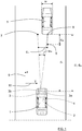
- Figure 1
- shows a schematic top view of an ego vehicle and a target vehicle;
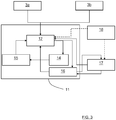
- Figure 2
- shows a schematical view of a first example;
- Figure 3
- shows a schematical view of a second example;
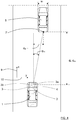
- Figure 4
- shows a schematic top view of an ego vehicle and a target vehicle according to a third example;
- Figure 5
- shows a schematical view of a camera sensor device;
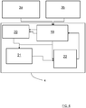
- Figure 6
- shows a schematical view of the third example; and
- Figure 7
- shows a flowchart for a method according to the present disclosure.
- With reference to
Figure 1 , showing a top view of anego vehicle 1, theego vehicle 1 comprises a vehicleenvironment detection system 2 that in turn comprises asensor arrangement 3 and acontrol unit 4. - The
sensor arrangement 3 comprises a firstsensor arrangement part 3a and a secondsensor arrangement part 3b, where the firstsensor arrangement part 3a comprises an environment data input device in the form of acamera sensor device 3a. The secondsensor arrangement part 3b comprises an environment data input device in the form of aradar sensor device 3b, where thesensor devices control unit 4. - In
Figure 1 , theego vehicle 1 is travelling behind atarget vehicle 5 along anx-direction 9, and thecamera sensor device 3a detects a measuredcamera detection 6 and theradar sensor device 3b detects a radar measureddetection 7. The measureddetections real detection 8 on thetarget vehicle 5, but due to inherent sensor errors the measureddetections real detection 8. - The sensor error of the
camera sensor device 3a is due to the use of model parameters, where a model parameter can be an internal parameter, such as an assumed constant fixed width wf of all target vehicles. These model parameters can contain systematic errors, for example in the present case thetarget vehicle 5 has an actual target vehicle width wr. - Instead of having a fixed assumption about the model parameter, the sensor can wait until the object is seen by both sensors for the first time and directly estimate the model parameter. Since the underlying principal is identic, in this context the term systematic error refers to a direct estimation of model parameters as well.
- The sensor error of the
radar sensor device 3b is due to its mounting orientation, which is a sensor specific model parameter. - The
camera sensor device 3a thus has a detection error dce in thex-direction 9, conferring the camera measured detection 6 a systematic error. Theradar sensor device 3b has a detection error dre in a y-direction 10 perpendicular to thex-direction 9, where said detection error dre is due to a misalignment error angle ϕre, conferring the radar measured detection 7 a systematic error as well. - With reference also to
Figure 2 , sensor measurements are sent to a centralobject tracking unit 11 comprised in thecontrol unit 4. This comprises according to some aspects a Kalman Filter; other realization could be a particle filter or just an association algorithm. A track is in this context defined by at least a filter state that consists of the position and its derivatives; at least velocity, but can contain also acceleration and higher derivatives or heading and yaw rate and higher derivatives. - According to the present disclosure, systematic errors in a certain direction for one
sensor arrangement part sensor part sensor arrangement part - The model parameters of the sensor can now be estimated in a single radar cycle or multiple radar cycles, when input from the
camera sensor device 3a is available. If the parameter is estimated, all future measurements associated to this target can be corrected, before it updates the track. In this context, a radar cycle is one observation phase during which the vehicleenvironment detection system 2 is arranged to acquire data, process said data on several signal processing levels and to send out available results. This can be a fixed time interval, or it can be a dynamic time interval depending on environment conditions and processing load. - In the following, a first example will be described.
- For the
camera sensor device 3a, according to some aspects, it is arranged to assume a fixed width wf of all targets that is 1,8m, while in this example thetarget vehicle 5 has a real target vehicle width wr that is 2,00m. This means that the relative width error is 10%, and hence the distance from thecamera sensor device 3a to the target vehicle has the same error. - In this case, if the target vehicle is at a real distance dr that is 100m, the camera measured
detection 6 is at a camera measured distance dc that is 90m. Theradar sensor device 3b does not have any detection error in thex-direction 9, and detects the radar measureddetection 7 at a radar measured distance dra that equals the real distance dr. By means of this information, thecontrol unit 4 is arranged to calculate the real target vehicle width wr, or at least an estimate of the real target vehicle width wr, by multiplying the fixed width wf with the relation between the radar measured distance dra, here also the real distance dr, and the camera measured distance dc, here 1.8m * (100m / 90m) = 2m. - In practice, the radar measured distance dra can deviate from the real distance dr, and generally the camera measured distance dc differs from the radar measured distance dra that is closer to a real distance dr than the camera measured distance dc. The correct width can be estimated over multiple cycles e.g. by taking the average or using a Kalman Filter, taking measurement uncertainties into account.
- In the following, the systematic error of the camera detections is known, and if in a next camera cycle the camera measured distance dc is 84m, this position is corrected by multiplying it with the relation between the real target vehicle width wr and the fixed width wf, here 84 * 2m/1,9m = 88,4m. This means that even if the
radar sensor device 3b no longer is able to detect an object, the error of thecamera sensor device 3a can still be more or less eliminated; in practice reduced to a very small measurement noise value. The camera measureddetection 6 can now be corrected to more or less coincide with thereal detection 8. - In
Figure 1 , for reasons of clarity, thecamera sensor device 3a and theradar sensor device 3b are placed at the same positon in thex-direction 9. This may not be the case in practice, but a difference between thecamera sensor device 3a and theradar sensor device 3b in thex-direction 9 is previously known and can be compensated for when performing the above calculations. All distances are assumed to be measured between a present detection and a sensor device that detects the present detection. - Alternatively, all distances are according to some aspects assumed to be measured between a present detection and one or more fixed reference points, where the mounting positions of the sensor devices relative said one or more fixed reference points are previously known.
- In addition to present object states, the error model parameters are estimated and integrated in an association and
update unit 12 in the centralobject tracking unit 11 as illustrated inFigure 2 . The association andupdate unit 12 therefore comprises a corresponding modelparameter correction unit - During association, measurements are associated with tracks, and using this association, the measurements update the corresponding track in a following update step. The updated track is sent to an
object state unit 14 that is connected to aprediction unit 15 that in turn is connected back to the association andupdate unit 12. A modelparameter estimate unit 16 is arranged to receive information from the association andupdate unit 12 and to estimate the model parameters of thesensor arrangement parts update unit 12 before it updates the track. - In a relatively uncomplicated case, the association step consists of a check of the position derivation between measurement and track. If the deviation exceeds a threshold, no update is performed. If there is a systematic error present, which cannot be handled by a Kalman filter or the like, the association fails. With the correction of systematic errors, association performance is therefore increased.
- During update, the track state, e.g. position, is updated with the current measurement, e.g. measured position. Most tracking algorithms assume that there is no systematic error presents, but only a measurement uncertainty. With the correction of systematic errors, a more precise estimation of the state is achieved.
- During update, the systematic errors can be limited to a certain value, enabling unrealistic estimates to be suppressed, e.g. for a Kalman Filter using pseudo measurements/limit max value.
- In the first example, only parameter errors of single objects are shown. With reference to
Figure 1 andFigure 3 , a further example will be shown. Here, systematic sensor parameters affecting all objects are estimated. - In the same way, the systematic error of the
radar sensor device 3b can also be identified and compensated for. The radar measureddetection 7 has a detection error dre in the y-direction 10 due to a misalignment of a certain angular value ϕre. By using the corrected camera measured detection, the detection error dre can be determined and since the real distance dr is known, the misalignment error angle ϕre can be determined and compensated for. - This means that even if the
camera sensor deice 3a no longer is able to detect an object, the misalignment error angle ϕre can still be more or less eliminated. In a practical application this can not only be done in a single measurement, but based on all associated objects from camera and radar. After calculating the error, even radar objects which are not associated to camera objects can be compensated. - Using the above corrections, the measured
detections camera sensor device 3a has a high accuracy in the y-direction 10, and theradar sensor device 3b in thex-direction 9, so that the fused object after compensation of systematic errors is more accurate in both these directions. - Another systematic error is e.g. due to if the
camera sensor device 3a calculates a ground plane, and this ground plane has a systematic error resulting in that all measurements are misplaced.Figure 3 corresponds toFigure 2 with some additions. - For each target, which is measured by both
sensors devices parameter estimate unit 16. Using the estimated model parameters of all targets from the modelparameter estimate unit 16, a common parameter such as for example orientation of theradar sensor device 3b, is calculated in a common modelparameter calculation unit 17. Having acquired this common parameter, all measurements of thecorresponding sensor device parameter estimate unit 16 and also to the association andupdate unit 12. - A common parameter is thus calculated taking all tracks classified as vehicles into account. These common parameters can be used to correct the individual parameter estimates, e.g. average, weighted average. A covariance matrix of the estimated parameters can be taken into account as a weighting factor. The estimation itself is according to some aspects a linear regression or a second Kalman Filter. Furthermore, this has the advantage that if a new measurement classified as a vehicle arrives, the scaling error can be initialized directly. This increases the association performance in the first radar cycles when a new object is detected. As a result, a gating area when a measurement is associated with a track can be lowered.
- In addition, according to some aspects, a
database unit 18 comprising common model parameters is used, being connected to the association andupdate unit 12 and the common modelparameter calculation unit 17 as indicated with dashed arrows inFigure 3 . This is a fixed memory module where model parameters of previous runs are calculated, such as for example a mounting orientation which was estimated the day before. - The data comprised in the
database unit 18 can for example be used initially in the association andupdate unit 12 for initialization of new tracks, when no estimate is present yet, or can be used in the common modelparameter calculation unit 17 to stabilize the common model parameters. This has the advantage that there is always an initial estimate of common model parameters. Furthermore, the common model parameters are more stable, if previous estimates are integrated in the common model parameter calculation. - According to some aspects, in an example, it is assumed that the
radar sensor device 3b is misaligned 3 degrees. In average, radar measurements will consequently be misaligned within 3 degrees. Taking all measurements from all targets, which are detected by theradar sensor device 3b and thecamera sensor device 3a, the angular deviation between theradar sensor device 3b and thecamera sensor device 3a is in average 3 degrees. This is determined in the in the modelparameter estimate unit 16. - Since this deviation varies due to measurement noise of both
sensor devices parameter calculation unit 17. - When the model parameter has been estimated, in the next radar cycle the measurements acquired from the
radar sensor device 3b are rotated by -3 degrees. It is likely that the mounting orientation does not change in short term, so this value is stored indatabase unit 18. In this way, at the next radar cycle, even the first measurements from theradar sensor device 3b can be corrected. - In order to enable estimation of the systematic errors, multiple solutions are according to some aspects possible. Since an estimate of a single measurement has a high uncertainty, multiple measurements are taken into account. If the error is object dependent, this has to be done separately for each object.
- Distinction criteria based on data storage can according to some aspects be:
- Recursive such that only current estimate has to be stored, resulting in less memory consumption; can for example be realized with a Kalman Filter.
- Storage of samples, e.g. ring-buffer, such that a certain amount of single estimates are stored and an estimate over time is calculated and enabling use of robust algorithms; can for example be realized with regression calculation, such as Least-Squares or weighted Total-Least-Squares, and in combination with robust approaches e.g. RANSAC (Random sample consensus).
- Distinction criteria based on combination with track states can according to some aspects be:
- Direct estimation of states of an object and systematic errors where cross-correlation is taken into account, while having a higher computational complexity; is augmented with a recursive Kalman Filter.
- Separate estimation of systematic error and object states; for regression calculation and with a separate recursive Kalman Filter.
- With reference to
Figure 4 ,Figure 5 andFigure 6 , a third example is shown. Infigure 4 , thetarget vehicle 5 in front of theego vehicle 1 is detected by theradar sensor device 3b and thecamera sensor device 3a. Theradar sensor device 3b is adapted to provide a radar measured distance dra, that constitutes an estimation of the real distance dr, to a certain radar detection 7' on thetarget vehicle 5, while thecamera sensor device 3a, which is schematically shown inFigure 5 , is adapted to provide a detected pixel width wp of thetarget vehicle 5 in camera pixels, which can be mapped using the focal length f of thecamera sensor device 3a to real coordinates. The focal length f is measured between acamera lens 26 and acamera image sensor 27, and the pixel width wp corresponds to a width on thecamera image sensor 27. - The real width wr is calculated as
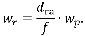
- It is here assumed that the radar measured distance dra equals the real distance dr, since in practice the difference normally is negligible. As mentioned previously, the correct width can be estimated over multiple cycles e.g. by taking the average or using a Kalman Filter, taking measurement uncertainties into account. Generally, an estimation of the real width wr is calculated according to the above, although in the following, it will be referred to as the real width.
- Having retrieved the real width wr, an essentially exact position can be estimated in the following radar cycles using data from the
camera sensor device 3a and the object width wr, even if thetarget vehicle 5 is no longer detectable by theradar sensor device 3b. - Knowing the real width wr and the pixel width wp enables the real distance dr to be calculated as:

- Knowing the real distance dr and a pixel displacement ddp at the
camera image sensor 27, a displacement angle ϕd can be determined as:
- Then a real displacement ddr can be calculated as:

- The third example is disclosed in schematical form in
Figure 6 , where thecamera sensor device 3a is arranged to detect a rear end of target vehicles and to determine the pixel width wp. Theradar sensor device 3b is arranged to estimate the real distance dr to thetarget vehicle 5. Thesensor devices association unit 19 that is arranged to associate the data from thesensor devices - The
association unit 19 provides input to awidth estimation unit 20 that performs a first estimation of an object width followed by an updating step for the object width. - The
association unit 19 and thewidth estimation unit 20 provide input to acalculation unit 21 that is arranged to calculate Cartesian coordinates for the measurements from thecamera sensor device 3a. Theassociation unit 19, thewidth estimation unit 20 and thecalculation unit 21 all provide input to a tracking unit 22 that is arranged to track objects over multiple radar cycles, and to provide input to theassociation unit 19. - All calculations, processes etc. are assumed to be performed by means of the
control unit 4. - The
above units control unit 4. Generally, thecontrol unit 4 can be comprised by one or more separate or integrated control units. - Generally, not only the rear part of the
target vehicle 5 can be detected, but also the front part for the case of an oncoming target vehicle, both based on the width of thetarget vehicle 5. Another option is available for crossing target vehicles where the length of thetarget vehicle 5 can be estimated to determine the distance to thetarget vehicle 5. - With reference to
Figure 7 , the present disclosure relates to a method for determining one or more systematic errors in acertain direction sensor arrangement part environment detection system 2 having at least twosensor arrangement parts - 23: Acquiring sensor data from said
sensor arrangement part - 24: Acquiring sensor data from another
sensor arrangement part sensor arrangement part certain direction sensor arrangement part - 25: Determining one or more systematic errors in said
certain direction sensor arrangement part sensor arrangement parts - The present disclosure is not limited to the examples above, but may vary freely within the scope of the appended claims. For example, the
camera sensor device 3a comprises at least one camera device, where each camera device is arranged for capturing images that either are monochrome or with color, and may be active, i.e. equipped with illumination means. Two or more camera devices may be arranged to produce 3-dimensional picture views. - Generally, the
sensor arrangement 3 comprises at least a firstsensor arrangement part 3a and a secondsensor arrangement part 3b, where thesensor arrangement parts sensor arrangement part sensor arrangement part 3a. 3b. Asensor arrangement part - In accordance with the present disclosure, one sensor arrangement part is more accurate in a certain dimension than another sensor arrangement part, and measurements from the more accurate sensor arrangement part are used for correcting measurements from the less accurate sensor arrangement part in said dimension.
- The present disclosure enables a plurality of paths for handling systematic errors:
- Systematic errors can be calculated based for a single object in a single measurement or over multiple measurements, e.g. average, weighted average, Kalman Filter, or Linear Regression.
- Systematic errors can be calculated for all objects detected by a sensor device in a single measurement or during multiple measurements.
- Systematic errors can be saved in a non-volatile memory, such that after a system restart, systematic errors which change relatively slowly can be directly re-used.
- For a systematic error, an uncertainty or variance, is calculated, e.g. by Least Squares or variance of the estimated width over multiple cycles. The uncertainty of a systematic error is used such that after compensation, the covariances resulting from measurement uncertainty of the detected objects are adapted based on the measurement uncertainty and the uncertainty of the correction parameter
- Instead of the estimation of a systematic error in a model parameters, the model parameters itself can be estimated.
- Generally, the present disclosure relates to a vehicle
environment detection system 2 comprising acontrol unit 4 and asensor arrangement 3 that in turn comprises at least twosensor arrangement parts control unit 4 is arranged to determine one or more systematic errors in acertain direction sensor arrangement part sensor arrangement part sensor arrangement part sensor arrangement part certain direction sensor arrangement part - According to some aspects, the vehicle
environment detection system 2 is arranged to be mounted to an ego vehicle adapted to be running forward in anx-direction 9, where a first sensor arrangement part is in the form of acamera sensor device 3a and a second sensor arrangement part is in the form of aradar sensor device 3b, where thecamera sensor device 3a has a detection error in thex-direction 9, and where theradar sensor device 3b has a detection error in a y-direction 10, perpendicular to thex-direction 9. - According to some aspects, the
camera sensor device 3a is arranged to assume a fixed width wf of all targets while atarget vehicle 5 has a real target vehicle width wr, where a camera measureddetection 6 is detected at a camera measured distance dc that differs from a radar measured distance dra of a detected radar measureddetection 7, where the radar measured distance dra is closer to a real distance dr than the camera measured distance dc, where thecontrol unit 4 is arranged to calculate an estimate of the real target vehicle width wr by multiplying the fixed width wf with a relation between the radar measured distance dra and the camera measured distance dc. - According to some aspects, the
radar sensor device 3b is adapted to provide a radar measured distance dra to a certain detection on atarget vehicle 5, while thecamera sensor device 3a is adapted to provide detected pixel width wp of thetarget vehicle 5 in camera pixels, where thecontrol unit 4 is arranged to calculate an estimated real width wr of thetarget vehicle 5 according to
camera sensor device 3a and wp is the detected pixel width. - According to some aspects, the
camera sensor device 3a is adapted to provide a pixel displacement ddp in camera pixels corresponding to a lateral displacement in the y-direction 10 of thetarget vehicle 5 relative theego vehicle 1, where thecontrol unit 4 is arranged to calculate a displacement angle ϕd as:
- According to some aspects, the
control unit 4 is arranged to calculate a real displacement ddr as:
- Generally, the present disclosure also relates to a method for determining one or more systematic errors in a
certain direction sensor arrangement part environment detection system 2 having at least twosensor arrangement parts - 23: acquiring sensor data from said
sensor arrangement part - 24: acquiring sensor data from another
sensor arrangement part sensor arrangement part certain direction sensor arrangement part - 25: determining one or more systematic errors in said
certain direction sensor arrangement part sensor arrangement parts - According to some aspects, the vehicle
environment detection system 2 is used in an ego vehicle adapted to be running forward in anx-direction 9, where a first sensor arrangement part is in the form of acamera sensor device 3a and a second sensor arrangement part is in the form of aradar sensor device 3b, where thecamera sensor device 3a has a detection error in thex-direction 9, and where theradar sensor device 3b has a detection error in a y-direction 10, perpendicular to thex-direction 9. - According to some aspects, the method comprises assuming a fixed width wf of all targets for the
camera sensor device 3a, while atarget vehicle 5 has a real target vehicle width wr, where a camera measureddetection 6 is detected at a camera measured distance dc that differs from a radar measured distance dra of a detected radar measureddetection 7, where the radar measured distance dra is closer to a real distance dr than the camera measured distance dc, where the method further comprises calculating an estimate of the real target vehicle width wr by multiplying the fixed width wf with a relation between the radar measured distance dra and the camera measured distance dc. - According to some aspects, the method comprises providing a radar measured distance dra to a certain detection on a
target vehicle 5, while thecamera sensor device 3a is used for providing detected pixel width wp of thetarget vehicle 5 in camera pixels, where the method further comprises calculating an estimation of a real width wr of thetarget vehicle 5 according to
camera sensor device 3a and wp is the detected pixel width. - According to some aspects, the
camera sensor device 3a is used for providing a pixel displacement ddp in camera pixels corresponding to a lateral displacement in the y-direction 10 of thetarget vehicle 5 relative theego vehicle 1, where the method further comprises calculating a displacement angle ϕd as:
- According to some aspects, the method further comprises calculating a real displacement ddr as:

Claims (12)
- A vehicle environment detection system (2) comprising a control unit (4) and a sensor arrangement (3) that in turn comprises at least two sensor arrangement parts (3a, 3b), characterized in that the control unit (4) is arranged to determine one or more systematic errors in a certain direction (9, 10) for one sensor arrangement part (3a, 3b) by combining acquired sensor data for said sensor arrangement part (3a, 3b) with acquired sensor data from another sensor arrangement part (3b, 3a), which another sensor arrangement part (3b, 3a) has a lower degree of systematic error in said certain direction (9, 10) than said sensor arrangement part (3a, 3b).
- The vehicle environment detection system (2) according to claim 1, characterized in that the vehicle environment detection system (2) is arranged to be mounted to an ego vehicle adapted to be running forward in an x-direction (9), where a first sensor arrangement part is in the form of a camera sensor device (3a) and a second sensor arrangement part is in the form of a radar sensor device (3b), where the camera sensor device (3a) has a detection error in the x-direction (9), and where the radar sensor device (3b) has a detection error in a y-direction (10), perpendicular to the x-direction (9).
- The vehicle environment detection system (2) according to claim 2, characterized in that the camera sensor device (3a) is arranged to assume a fixed width (wf) of all targets while a target vehicle (5) has a real target vehicle width (wr), where a camera measured detection (6) is detected at a camera measured distance (dc) that differs from a radar measured distance (dra) of a detected radar measured detection (7), where the radar measured distance (dra) is closer to a real distance (dr) than the camera measured distance (dc), where the control unit (4) is arranged to calculate an estimate of the real target vehicle width (wr) by multiplying the fixed width (wf) with a relation between the radar measured distance (dra) and the camera measured distance (dc).
- The vehicle environment detection system (2) according to any one of the claims 2 or 3, characterized in that the radar sensor device (3b) is adapted to provide a radar measured distance (dra) to a certain detection on a target vehicle (5), while the camera sensor device (3a) is adapted to provide detected pixel width (wp) of the target vehicle (5) in camera pixels, where the control unit (4) is arranged to calculate an estimated real width (wr) of the target vehicle (5) according to

- The vehicle environment detection system (2) according to claim 4, characterized in that the camera sensor device (3a) is adapted to provide a pixel displacement (ddp) in camera pixels corresponding to a lateral displacement in the y-direction (10) of the target vehicle (5) relative the ego vehicle (1), where the control unit (4) is arranged to calculate a displacement angle (ϕd) as:

- The vehicle environment detection system (2) according to claim 5, characterized in that the control unit (4) is arranged to calculate a real displacement (ddr) as:

- A method for determining one or more systematic errors in a certain direction (9, 10) for at least one sensor arrangement part (3a, 3b) used in a vehicle environment detection system (2) having at least two sensor arrangement parts (3a, 3b), characterized in that the method comprises:(23) acquiring sensor data from said sensor arrangement part (3a, 3b);(24) acquiring sensor data from another sensor arrangement part (3b, 3a), which another sensor arrangement part (3b, 3a) has a lower degree of systematic error in said certain direction (9, 10) than said sensor arrangement part (3a, 3b); and(25) determining one or more systematic errors in said certain direction (9, 10) for said sensor arrangement part (3a, 3b) by combining the acquired sensor data from said sensor arrangement parts (3b, 3a).
- The method according to claim 7, characterized in that the vehicle environment detection system (2) is used in an ego vehicle adapted to be running forward in an x-direction (9), where a first sensor arrangement part is in the form of a camera sensor device (3a) and a second sensor arrangement part is in the form of a radar sensor device (3b), where the camera sensor device (3a) has a detection error in the x-direction (9), and where the radar sensor device (3b) has a detection error in a y-direction (10), perpendicular to the x-direction (9).
- The method according to claim 8, characterized in that the method comprises assuming a fixed width (wf) of all targets for the camera sensor device (3a), while a target vehicle (5) has a real target vehicle width (wr), where a camera measured detection (6) is detected at a camera measured distance (dc) that differs from a radar measured distance (dra) of a detected radar measured detection (7), where the radar measured distance (dra) is closer to a real distance (dr) than the camera measured distance (dc), where the method further comprises calculating an estimate of the real target vehicle width (wr) by multiplying the fixed width (wf) with a relation between the radar measured distance (dra) and the camera measured distance (dc).
- The method according to any one of the claims 8 or 9, characterized in that the method comprises providing a radar measured distance (dra) to a certain detection on a target vehicle (5), while the camera sensor device (3a) is used for providing detected pixel width (wp) of the target vehicle (5) in camera pixels, where the method further comprises calculating an estimation of a real width (wr) of the target vehicle (5) according to

- The method according to claim 10, characterized in that the camera sensor device (3a) is used for providing a pixel displacement (ddp) in camera pixels corresponding to a lateral displacement in the y-direction (10) of the target vehicle (5) relative the ego vehicle (1), where the method further comprises calculating a displacement angle (ϕd) as:

- The vehicle environment detection system (2) according to claim 11, characterized in that the method further comprises calculating a real displacement (ddr) as:

Priority Applications (3)
| Application Number | Priority Date | Filing Date | Title |
|---|---|---|---|
| EP17175647.1A EP3415943A1 (en) | 2017-06-13 | 2017-06-13 | Error estimation for a vehicle environment detection system |
| PCT/EP2018/064780 WO2018228869A1 (en) | 2017-06-13 | 2018-06-05 | Error estimation for a vehicle environment detection system |
| US16/621,826 US11327154B2 (en) | 2017-06-13 | 2018-06-05 | Error estimation for a vehicle environment detection system |
Applications Claiming Priority (1)
| Application Number | Priority Date | Filing Date | Title |
|---|---|---|---|
| EP17175647.1A EP3415943A1 (en) | 2017-06-13 | 2017-06-13 | Error estimation for a vehicle environment detection system |
Publications (1)
| Publication Number | Publication Date |
|---|---|
| EP3415943A1 true EP3415943A1 (en) | 2018-12-19 |
Family
ID=59055071
Family Applications (1)
| Application Number | Title | Priority Date | Filing Date |
|---|---|---|---|
| EP17175647.1A Withdrawn EP3415943A1 (en) | 2017-06-13 | 2017-06-13 | Error estimation for a vehicle environment detection system |
Country Status (3)
| Country | Link |
|---|---|
| US (1) | US11327154B2 (en) |
| EP (1) | EP3415943A1 (en) |
| WO (1) | WO2018228869A1 (en) |
Cited By (4)
| Publication number | Priority date | Publication date | Assignee | Title |
|---|---|---|---|---|
| WO2020235467A1 (en) * | 2019-05-23 | 2020-11-26 | 日立オートモティブシステムズ株式会社 | Vehicle control system, and vehicle control device |
| US11327169B2 (en) * | 2018-10-10 | 2022-05-10 | Mando Mobility Solutions Corporation | Apparatus and method for complementing automotive radar |
| US11402467B2 (en) * | 2018-12-29 | 2022-08-02 | Yandex Self Driving Group Llc | Methods and computer devices for determining angular offset of radar system |
| DE102023205459A1 (en) * | 2023-06-13 | 2024-12-19 | Robert Bosch Gesellschaft mit beschränkter Haftung | Method for controlling a robot device |
Families Citing this family (6)
| Publication number | Priority date | Publication date | Assignee | Title |
|---|---|---|---|---|
| JP6970065B2 (en) * | 2018-09-06 | 2021-11-24 | 株式会社Soken | Object detector |
| JP6735801B2 (en) * | 2018-10-16 | 2020-08-05 | 三菱電機株式会社 | Object recognition device, vehicle control device using the same, object recognition method, and vehicle control method using the same |
| DE102019102679B4 (en) * | 2019-02-04 | 2026-01-29 | Bayerische Motoren Werke Aktiengesellschaft | Method, device, computer program and computer program product for providing a trajectory of an object to a vehicle for use in vehicle control functions |
| DE112020003137T5 (en) * | 2019-08-02 | 2022-04-07 | Hitachi Astemo, Ltd. | TARGET DEVICE, DRIVING CONTROL SYSTEM AND METHOD FOR CALCULATING A CORRECTION VALUE OF SENSOR DATA |
| CN116052121B (en) * | 2023-01-28 | 2023-06-27 | 上海芯算极科技有限公司 | Multi-sensing target detection fusion method and device based on distance estimation |
| JP7843735B2 (en) * | 2023-05-31 | 2026-04-10 | 三菱電機モビリティ株式会社 | Object recognition device and object recognition method |
Citations (6)
| Publication number | Priority date | Publication date | Assignee | Title |
|---|---|---|---|---|
| EP1462823A1 (en) * | 2003-03-28 | 2004-09-29 | Fujitsu Limited | Collision prediction device, method of predicting collision, and computer product |
| DE102007018470A1 (en) * | 2007-04-19 | 2008-10-23 | Robert Bosch Gmbh | Driver assistance system and method for object plausibility |
| US20080300787A1 (en) * | 2006-02-03 | 2008-12-04 | Gm Global Technology Operations, Inc. | Method and apparatus for on-vehicle calibration and orientation of object-tracking systems |
| EP2639781A1 (en) * | 2012-03-14 | 2013-09-18 | Honda Motor Co., Ltd. | Vehicle with improved traffic-object position detection |
| US20160116573A1 (en) | 2014-10-24 | 2016-04-28 | Texas Instruments Incorporated | Method and apparatus for generating alignment matrix for camera-radar system |
| DE112014005376T5 (en) * | 2013-12-26 | 2016-08-11 | Mitsubishi Electric Corporation | Information processing apparatus, information processing method and program |
Family Cites Families (8)
| Publication number | Priority date | Publication date | Assignee | Title |
|---|---|---|---|---|
| US4713768A (en) * | 1984-02-20 | 1987-12-15 | Hitachi, Ltd. | Method of localizing a moving body |
| DE19641261C1 (en) * | 1996-10-07 | 1998-02-12 | Siemens Ag | Distance sensor measuring quality evaluation method |
| SE510844C2 (en) * | 1997-11-03 | 1999-06-28 | Celsiustech Syst Ab | Automatic compensation of systematic errors in target tracking with multiple sensors |
| DE10149115A1 (en) * | 2001-10-05 | 2003-04-17 | Bosch Gmbh Robert | Object detection device for motor vehicle driver assistance systems checks data measured by sensor systems for freedom from conflict and outputs fault signal on detecting a conflict |
| US20070182623A1 (en) * | 2006-02-03 | 2007-08-09 | Shuqing Zeng | Method and apparatus for on-vehicle calibration and orientation of object-tracking systems |
| CN101231340A (en) * | 2007-12-29 | 2008-07-30 | 四川川大智胜软件股份有限公司 | Error registration method for processing track amalgamation of multiple radar system |
| GB2501062B (en) | 2012-03-14 | 2014-08-13 | Toshiba Res Europ Ltd | A text to speech method and system |
| FR3036204B1 (en) * | 2015-05-11 | 2018-06-15 | Valeo Schalter Und Sensoren Gmbh | ERROR COMPENSATION METHOD AND SYSTEM FOR AN INBOARD OBJECT DETECTION SYSTEM ON A MOTOR VEHICLE |
-
2017
- 2017-06-13 EP EP17175647.1A patent/EP3415943A1/en not_active Withdrawn
-
2018
- 2018-06-05 US US16/621,826 patent/US11327154B2/en active Active
- 2018-06-05 WO PCT/EP2018/064780 patent/WO2018228869A1/en not_active Ceased
Patent Citations (6)
| Publication number | Priority date | Publication date | Assignee | Title |
|---|---|---|---|---|
| EP1462823A1 (en) * | 2003-03-28 | 2004-09-29 | Fujitsu Limited | Collision prediction device, method of predicting collision, and computer product |
| US20080300787A1 (en) * | 2006-02-03 | 2008-12-04 | Gm Global Technology Operations, Inc. | Method and apparatus for on-vehicle calibration and orientation of object-tracking systems |
| DE102007018470A1 (en) * | 2007-04-19 | 2008-10-23 | Robert Bosch Gmbh | Driver assistance system and method for object plausibility |
| EP2639781A1 (en) * | 2012-03-14 | 2013-09-18 | Honda Motor Co., Ltd. | Vehicle with improved traffic-object position detection |
| DE112014005376T5 (en) * | 2013-12-26 | 2016-08-11 | Mitsubishi Electric Corporation | Information processing apparatus, information processing method and program |
| US20160116573A1 (en) | 2014-10-24 | 2016-04-28 | Texas Instruments Incorporated | Method and apparatus for generating alignment matrix for camera-radar system |
Cited By (7)
| Publication number | Priority date | Publication date | Assignee | Title |
|---|---|---|---|---|
| US11327169B2 (en) * | 2018-10-10 | 2022-05-10 | Mando Mobility Solutions Corporation | Apparatus and method for complementing automotive radar |
| US11402467B2 (en) * | 2018-12-29 | 2022-08-02 | Yandex Self Driving Group Llc | Methods and computer devices for determining angular offset of radar system |
| WO2020235467A1 (en) * | 2019-05-23 | 2020-11-26 | 日立オートモティブシステムズ株式会社 | Vehicle control system, and vehicle control device |
| JPWO2020235467A1 (en) * | 2019-05-23 | 2020-11-26 | ||
| US12151714B2 (en) | 2019-05-23 | 2024-11-26 | Hitachi Astemo, Ltd. | Vehicle control system and vehicle control method |
| DE102023205459A1 (en) * | 2023-06-13 | 2024-12-19 | Robert Bosch Gesellschaft mit beschränkter Haftung | Method for controlling a robot device |
| US12522230B2 (en) | 2023-06-13 | 2026-01-13 | Robert Bosch Gmbh | Method for controlling a robotic device |
Also Published As
| Publication number | Publication date |
|---|---|
| WO2018228869A1 (en) | 2018-12-20 |
| US20210302534A1 (en) | 2021-09-30 |
| US11327154B2 (en) | 2022-05-10 |
Similar Documents
| Publication | Publication Date | Title |
|---|---|---|
| US11327154B2 (en) | Error estimation for a vehicle environment detection system | |
| EP3285230B1 (en) | Enhanced object detection and motion estimation for a vehicle environment detection system | |
| US7991550B2 (en) | Method and apparatus for on-vehicle calibration and orientation of object-tracking systems | |
| US9151626B1 (en) | Vehicle position estimation system | |
| US20100235129A1 (en) | Calibration of multi-sensor system | |
| JP6770393B2 (en) | Tracking device and program | |
| JP6533619B2 (en) | Sensor calibration system | |
| US20070182623A1 (en) | Method and apparatus for on-vehicle calibration and orientation of object-tracking systems | |
| US10508912B2 (en) | Road surface shape measuring device, measuring method, and non-transitory computer-readable medium | |
| US11914028B2 (en) | Object detection device for vehicle | |
| Nienaber et al. | A comparison of low-cost monocular vision techniques for pothole distance estimation | |
| JP6988873B2 (en) | Position estimation device and computer program for position estimation | |
| EP3361446B1 (en) | Imu-aided image registration | |
| CN109791408A (en) | Self-position estimates method and self-position estimating device | |
| CN106574961A (en) | Object recognition device using plurality of object detection means | |
| US20250029401A1 (en) | Image processing device | |
| AU2005250916A1 (en) | Image-augmented inertial navigation system (IAINS) and method | |
| JP7812476B2 (en) | Measurement device, measurement method, program, and storage medium | |
| Zhao et al. | An automatic online camera calibration system for vehicular applications | |
| JP7526858B2 (en) | Measurement device, measurement method, and program | |
| CN115902838A (en) | Using camera data to automatically detect the alignment status of the lidar to the vehicle | |
| US20180060671A1 (en) | Image processing device, imaging device, equipment control system, equipment, image processing method, and recording medium storing program | |
| JP7143947B2 (en) | SELF POSITION CORRECTION METHOD AND SELF POSITION CORRECTION DEVICE | |
| JP2024177451A (en) | Measurement device, measurement method, and program | |
| JP2024038322A (en) | Measuring device, measuring method and program |
Legal Events
| Date | Code | Title | Description |
|---|---|---|---|
| PUAI | Public reference made under article 153(3) epc to a published international application that has entered the european phase |
Free format text: ORIGINAL CODE: 0009012 |
|
| AK | Designated contracting states |
Kind code of ref document: A1 Designated state(s): AL AT BE BG CH CY CZ DE DK EE ES FI FR GB GR HR HU IE IS IT LI LT LU LV MC MK MT NL NO PL PT RO RS SE SI SK SM TR |
|
| AX | Request for extension of the european patent |
Extension state: BA ME |
|
| 17P | Request for examination filed |
Effective date: 20190618 |
|
| RBV | Designated contracting states (corrected) |
Designated state(s): AL AT BE BG CH CY CZ DE DK EE ES FI FR GB GR HR HU IE IS IT LI LT LU LV MC MK MT NL NO PL PT RO RS SE SI SK SM TR |
|
| 17Q | First examination report despatched |
Effective date: 20200720 |
|
| STAA | Information on the status of an ep patent application or granted ep patent |
Free format text: STATUS: THE APPLICATION IS DEEMED TO BE WITHDRAWN |
|
| 18D | Application deemed to be withdrawn |
Effective date: 20201201 |