EP3415934A1 - Method for estimating the covered area of a directive antenna of a local positioning system while setting up said system - Google Patents
Method for estimating the covered area of a directive antenna of a local positioning system while setting up said system Download PDFInfo
- Publication number
- EP3415934A1 EP3415934A1 EP17175719.8A EP17175719A EP3415934A1 EP 3415934 A1 EP3415934 A1 EP 3415934A1 EP 17175719 A EP17175719 A EP 17175719A EP 3415934 A1 EP3415934 A1 EP 3415934A1
- Authority
- EP
- European Patent Office
- Prior art keywords
- antenna
- area
- transponders
- estimating
- mth
- Prior art date
- Legal status (The legal status is an assumption and is not a legal conclusion. Google has not performed a legal analysis and makes no representation as to the accuracy of the status listed.)
- Granted
Links
Images

Classifications
-
- G—PHYSICS
- G01—MEASURING; TESTING
- G01R—MEASURING ELECTRIC VARIABLES; MEASURING MAGNETIC VARIABLES
- G01R29/00—Arrangements for measuring or indicating electric quantities not covered by groups G01R19/00 - G01R27/00
- G01R29/08—Measuring electromagnetic field characteristics
- G01R29/10—Radiation diagrams of antennas
-
- H—ELECTRICITY
- H04—ELECTRIC COMMUNICATION TECHNIQUE
- H04W—WIRELESS COMMUNICATION NETWORKS
- H04W16/00—Network planning, e.g. coverage or traffic planning tools; Network deployment, e.g. resource partitioning or cells structures
- H04W16/18—Network planning tools
- H04W16/20—Network planning tools for indoor coverage or short range network deployment
Definitions
- the invention relates to the field of local positioning systems having directive antennae.
- the invention relates to a method for estimating the covered area of a directive antenna of a local positioning system while setting up said system.
- LPS Local Positioning Systems
- State-of-the-art systems use time-of-arrival or time-difference-of-arrival measurements of electromagnetic waves. These electromagnetic waves travel between antennae with fixed and known positions and mobile transponders (tags) with unknown and variable positions. Using the timing measurements from several antennae with respect to the mobile transponder, the position of the mobile transponder in the coordinate system of the local positioning system can be determined. When such a mobile transponder is attached to an object or person, the position of this object or person can be determined from the position of the mobile transponder.
- 'range' shall mean the maximum distance to the antenna to which the transponder may be located in order to receive electromagnetic waves from said antenna.
- 'coverage area' shall mean the area on which the transponder must be located to receive electromagnetic waves from said antenna.
- a radiation pattern of a typical directive antenna is given in Fig.1a and 1b .
- Fig.1a shows the horizontal radiation pattern
- Fig.1b shows the vertical pattern.
- 'radiation pattern' refers to the angular dependence of the strength of the electromagnetic waves from the antenna.
- An important issue regarding the antenna coverage of an area of interest is the difficulty of finding out which area can be covered by which antenna during system setup.
- the position and orientation of each antenna is of vital importance for optimal coverage of the area of interest and hence for accurate and continuous position tracking.
- some heuristics for antennae placement have been proposed in the literature, finding the best positions and orientations is difficult in practice since the operator does not get any feedback about the current system coverage while setting up the system.
- the placement and orientation needs to be based on experience and rough manual estimates about which area is covered by a given antennae. Estimating the covered area is made even more difficult by obstacles in the line-of-sight of the antenna (ceiling, flags, etc.). Simulation of the signal propagation could provide some guidance for the operator, but these would require extensive modelling of the venue in order to obtain realistic results.
- the invention relates to a method for estimating the coverage area of a directive antenna of a local positioning system while setting up said system, said antenna being located in the vicinity of an area of interest, the method comprising the following steps:
- multiple transponders are distributed over the area of interest and the strength/quality or the signal transmission between these transponders and the antenna is measured.
- the coverage area of the antenna can be estimated. This approach facilitates the LPS setup because the operator can get feedback about the suitability of the installation while adjusting the antenna position and/or orientation. With this information, the coverage can be optimized by adapting the position and/or orientation of the antenna in an automated or manual way.
- the method according to the invention may comprise one or a combination of the following characteristics.
- the step of performing measurements comprises:
- the power indicator is the Received Signal Strength Indicator.
- the step of estimating the coverage area comprises sorting the transponders according to whether or not the signal they have emitted has been received by the antenna and according to the power indicators for the received signals.
- the step of estimating the coverage area comprises producing a coverage map of the area of interest, according to the sorting.
- the step of distributing comprises homogeneously spreading the transponders on the area of interest.
- the method MTH offered by the invention addresses the difficulty in estimating the coverage area of a directive antenna of a local positioning system.
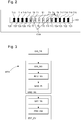
- Fig.2 shows such a directive antenna A1, located in the vicinity of an area of interest AOI.
- the coverage area CVA of said antenna A1 is approximated as a triangle.
- a plurality of test transponders T1-T28 are distributed over the area of interest AOI, advantageously in a homogenous manner, that is to say spread all over the area of interest AOI and regularly spaced, as shown in Fig.2 .
- a second step MSD_SS of the method MTH according to the invention measurements of signal strengths are performed.
- each of the test transponders T1-T28 emits a signal. Understandably, depending on its position and its orientation, the antenna A1 can only receive some of these signals. In the example of Fig.2 , only seven transponders T1-T7 out of the twenty-eight depicted transponders are in the coverage area CVA of the antenna A1.
- the antenna A1 receives some of the signals emitted by the transponders.
- a power indicator relative to each received signal is measured.
- the power indicator is for instance calculated using the Received Signal Strength Indicator (RRSI), which is a measurement of the power present in a received radio signal.
- RRSI Received Signal Strength Indicator
- Most positioning systems provide a value for the RSSI for each signal transmission between a transponder and an antenna. A high RSSI indicates good signal strength/quality and vice versa.
- the coverage area CVA of the antenna A1 is estimated, on the basis of said measurements.
- the test transponders T1-T28 are sorted in different categories, by using the measurements. For instance, the transponders the antenna received no signal from (T13-T28) are sorted in the category "no coverage”, and the others (T1-T12) are sorted in the categories "good signal quality", "medium signal quality” and "poor signal quality". Of course, other categories and a different number of categories are conceivable. In the example of Fig.2 , five categories are represented: from white which is equivalent to a good signal quality to black which is equivalent to no coverage.
- a coverage map is produced, by using the sorting. This provides intuitive feedback about the coverage of the antenna which helps optimizing the setup of the positioning system, that is to say find the optimal positions and orientations of the antenna, find out which parts of the area of interest are sufficiently covered, etc.
Landscapes
- Physics & Mathematics (AREA)
- Electromagnetism (AREA)
- General Physics & Mathematics (AREA)
- Engineering & Computer Science (AREA)
- Computer Networks & Wireless Communication (AREA)
- Signal Processing (AREA)
- Radar Systems Or Details Thereof (AREA)
- Position Fixing By Use Of Radio Waves (AREA)
Abstract
Description
- The invention relates to the field of local positioning systems having directive antennae. In particular, the invention relates to a method for estimating the covered area of a directive antenna of a local positioning system while setting up said system.
- In recent years, there has been an increasing demand for reliable and objective evaluation of sport specific data. The measurement and analysis of the trajectories of athletes is one possible approach to gain such insights. It allows the assessment of the physical performance and tactical behavior of athletes. Thus, it can yield helpful feedback for athletes, coaches and referees. Furthermore, spectators can be supplied with additional information about the accomplishments of their idols.
- Local Positioning Systems (LPS) provide a means for the measurement of athletes' positions and motion trajectories. State-of-the-art systems use time-of-arrival or time-difference-of-arrival measurements of electromagnetic waves. These electromagnetic waves travel between antennae with fixed and known positions and mobile transponders (tags) with unknown and variable positions. Using the timing measurements from several antennae with respect to the mobile transponder, the position of the mobile transponder in the coordinate system of the local positioning system can be determined. When such a mobile transponder is attached to an object or person, the position of this object or person can be determined from the position of the mobile transponder.
- Usually, directive antennae are preferred over omnidirectional antennae in order to extend the ranges of the radio coverage areas. Throughout this text, 'range' shall mean the maximum distance to the antenna to which the transponder may be located in order to receive electromagnetic waves from said antenna. In addition, 'coverage area' shall mean the area on which the transponder must be located to receive electromagnetic waves from said antenna.
- For illustrative purposes only, a radiation pattern of a typical directive antenna is given in
Fig.1a and 1b . In particular,Fig.1a shows the horizontal radiation pattern andFig.1b shows the vertical pattern. It is to be noted that 'radiation pattern' refers to the angular dependence of the strength of the electromagnetic waves from the antenna. - An important issue regarding the antenna coverage of an area of interest is the difficulty of finding out which area can be covered by which antenna during system setup. The position and orientation of each antenna is of vital importance for optimal coverage of the area of interest and hence for accurate and continuous position tracking. Although some heuristics for antennae placement have been proposed in the literature, finding the best positions and orientations is difficult in practice since the operator does not get any feedback about the current system coverage while setting up the system. Hence, the placement and orientation needs to be based on experience and rough manual estimates about which area is covered by a given antennae. Estimating the covered area is made even more difficult by obstacles in the line-of-sight of the antenna (ceiling, flags, etc.). Simulation of the signal propagation could provide some guidance for the operator, but these would require extensive modelling of the venue in order to obtain realistic results.
- It is an object of the invention to overcome these drawbacks.
- Hence, the invention relates to a method for estimating the coverage area of a directive antenna of a local positioning system while setting up said system, said antenna being located in the vicinity of an area of interest, the method comprising the following steps:
- Distributing a plurality of transponders over the area of interest
- Performing measurements of signal strength between the antenna and said transponders
- Estimating the coverage area by using said measurements.
- According to the invention, multiple transponders are distributed over the area of interest and the strength/quality or the signal transmission between these transponders and the antenna is measured. By combining these measurements, the coverage area of the antenna can be estimated. This approach facilitates the LPS setup because the operator can get feedback about the suitability of the installation while adjusting the antenna position and/or orientation. With this information, the coverage can be optimized by adapting the position and/or orientation of the antenna in an automated or manual way.
- Furthermore, the method according to the invention may comprise one or a combination of the following characteristics.
- In a non-limited embodiment, the step of performing measurements comprises:
- Emitting a signal by each of the plurality of transponders
- Receiving at least two of said signals by the antenna
- Measuring a power indicator for each received signals.
- In a non-limited embodiment, the power indicator is the Received Signal Strength Indicator.
- In a non-limited embodiment, the step of estimating the coverage area comprises sorting the transponders according to whether or not the signal they have emitted has been received by the antenna and according to the power indicators for the received signals.
- In a non-limited embodiment, the step of estimating the coverage area comprises producing a coverage map of the area of interest, according to the sorting.
- In a non-limited embodiment, the step of distributing comprises homogeneously spreading the transponders on the area of interest.
- Other features and advantages of the present invention will appear more clearly upon reading the following detailed description, made with reference to the annexed drawings, given by way of non-limiting example:
-
Fig.1a shows the horizontal radiation pattern of a typical directive antenna -
Fig.1b shows the vertical radiation pattern of the antenna to which reference has been made inFig.1a -
Fig.2 shows an environment comprising an area of interest on which a plurality of transponders are distributed, a directive antennae being located in the vicinity of said area of interest -
Fig.3 shows a flow diagram illustrating the steps of a method according to the invention. - The method MTH offered by the invention addresses the difficulty in estimating the coverage area of a directive antenna of a local positioning system.
Fig.2 shows such a directive antenna A1, located in the vicinity of an area of interest AOI. For illustrative purposes, the coverage area CVA of said antenna A1 is approximated as a triangle. - In a first step DIS_TR of the method MTH according to the invention, a plurality of test transponders T1-T28 are distributed over the area of interest AOI, advantageously in a homogenous manner, that is to say spread all over the area of interest AOI and regularly spaced, as shown in
Fig.2 . - In a second step MSD_SS of the method MTH according to the invention, measurements of signal strengths are performed.
- According to a sub-step EMT_SG of this second step MSD_SS, each of the test transponders T1-T28 emits a signal. Understandably, depending on its position and its orientation, the antenna A1 can only receive some of these signals. In the example of
Fig.2 , only seven transponders T1-T7 out of the twenty-eight depicted transponders are in the coverage area CVA of the antenna A1. - According a subsequent sub-step RCV_SG of this second step MSD_SS, as already mentioned, the antenna A1 receives some of the signals emitted by the transponders.
- According to a subsequent sub-step MSD_PI of this second step MSD_SS, a power indicator relative to each received signal is measured. The power indicator is for instance calculated using the Received Signal Strength Indicator (RRSI), which is a measurement of the power present in a received radio signal. Most positioning systems provide a value for the RSSI for each signal transmission between a transponder and an antenna. A high RSSI indicates good signal strength/quality and vice versa.
- In a third step EST_CV of the method MTH according to the invention, the coverage area CVA of the antenna A1 is estimated, on the basis of said measurements.
- According a sub-step SRT_TR of this third step EST_CV, the test transponders T1-T28 are sorted in different categories, by using the measurements. For instance, the transponders the antenna received no signal from (T13-T28) are sorted in the category "no coverage", and the others (T1-T12) are sorted in the categories "good signal quality", "medium signal quality" and "poor signal quality". Of course, other categories and a different number of categories are conceivable. In the example of
Fig.2 , five categories are represented: from white which is equivalent to a good signal quality to black which is equivalent to no coverage. - According a subsequent sub-step PRD_CM of this third step EST_CV, a coverage map is produced, by using the sorting. This provides intuitive feedback about the coverage of the antenna which helps optimizing the setup of the positioning system, that is to say find the optimal positions and orientations of the antenna, find out which parts of the area of interest are sufficiently covered, etc.
- Of course, the present invention is not limited to the illustrated example but may be subject to various variants and alterations, which will be apparent to those skilled in the art.
Claims (6)
- Method (MTH) for estimating the coverage area (CVA) of a directive antenna (A1) of a local positioning system while setting up said system, said antenna (A1) being located in the vicinity of an area of interest (AOI), the method (MTH) comprising the following steps:- Distributing (DIS_TR) a plurality of transponders (T1-T28) over the area of interest- Performing (MSD_SS) measurements of signal strength between the antenna (A1) and said transponders- Estimating (EST_CV) the coverage area (CVA) by using said measurements.
- Method (MTH) according to claim 1, wherein the step of performing (MSD_SS) measurements comprises:- Emitting (EMT_SG) a signal by each of the plurality of transponders (T1-T28)- Receiving (RCV_SG) at least two of said signals by the antenna (A1)- Measuring (MSD_PI) a power indicator for each received signals.
- Method (MTH) according to claim 2, wherein the power indicator is the Received Signal Strength Indicator.
- Method (MTH) according to claim 2 or claim 3, wherein the step of estimating (EST_CV) the coverage area (CVA) comprises sorting (SRT_TR) the transponders (T1-T28) according to whether or not the signal they have emitted has been received by the antenna (A1) and according to the power indicators for the received signals.
- Method (MTH) according to claim 4, wherein the step of estimating (EST_CV) the coverage area (CVA) comprises producing (PRD_CM) a coverage map of the area of interest (AOI), according to the sorting.
- Method (MTH) according to any of the previous claims, wherein the step of distributing (DIS_TR) comprises homogeneously spreading the transponders (T1-T28) on the area of interest (AOI).
Priority Applications (3)
| Application Number | Priority Date | Filing Date | Title |
|---|---|---|---|
| EP17175719.8A EP3415934B1 (en) | 2017-06-13 | 2017-06-13 | Method for estimating the covered area of a directive antenna of a local positioning system while setting up said system |
| US16/617,929 US11573255B2 (en) | 2017-06-13 | 2018-06-11 | Method for estimating the covered area of a directive antenna of a local positioning system while setting up said system |
| PCT/EP2018/065402 WO2018229014A1 (en) | 2017-06-13 | 2018-06-11 | Method for estimating the covered area of a directive antenna of a local positioning system while setting up said system |
Applications Claiming Priority (1)
| Application Number | Priority Date | Filing Date | Title |
|---|---|---|---|
| EP17175719.8A EP3415934B1 (en) | 2017-06-13 | 2017-06-13 | Method for estimating the covered area of a directive antenna of a local positioning system while setting up said system |
Publications (2)
| Publication Number | Publication Date |
|---|---|
| EP3415934A1 true EP3415934A1 (en) | 2018-12-19 |
| EP3415934B1 EP3415934B1 (en) | 2024-07-24 |
Family
ID=59257967
Family Applications (1)
| Application Number | Title | Priority Date | Filing Date |
|---|---|---|---|
| EP17175719.8A Active EP3415934B1 (en) | 2017-06-13 | 2017-06-13 | Method for estimating the covered area of a directive antenna of a local positioning system while setting up said system |
Country Status (3)
| Country | Link |
|---|---|
| US (1) | US11573255B2 (en) |
| EP (1) | EP3415934B1 (en) |
| WO (1) | WO2018229014A1 (en) |
Citations (3)
| Publication number | Priority date | Publication date | Assignee | Title |
|---|---|---|---|---|
| US5668562A (en) * | 1996-04-19 | 1997-09-16 | Lgc Wireless, Inc. | Measurement-based method of optimizing the placement of antennas in a RF distribution system |
| US20080182528A1 (en) * | 2007-01-31 | 2008-07-31 | Symbol Technologies, Inc. | Methods and Apparatus for Driving Radio Frequency Transmitter Placement Via an Enhanced Coverage Metric |
| US20150296388A1 (en) * | 2010-09-17 | 2015-10-15 | Consistel Pte Lte | Automatic network design |
Family Cites Families (3)
| Publication number | Priority date | Publication date | Assignee | Title |
|---|---|---|---|---|
| US6141558A (en) * | 1998-05-07 | 2000-10-31 | Motorola, Inc. | Method and apparatus for locating a subscriber unit in a communication system |
| PT1654561E (en) * | 2003-08-14 | 2012-10-24 | Saab Sensis Corp | Target localization using tdoa distributed antenna |
| EP3415946B1 (en) * | 2017-06-13 | 2021-08-04 | Swiss Timing Ltd. | Method for calculating a position of a transponder within an area of interest |
-
2017
- 2017-06-13 EP EP17175719.8A patent/EP3415934B1/en active Active
-
2018
- 2018-06-11 WO PCT/EP2018/065402 patent/WO2018229014A1/en not_active Ceased
- 2018-06-11 US US16/617,929 patent/US11573255B2/en active Active
Patent Citations (3)
| Publication number | Priority date | Publication date | Assignee | Title |
|---|---|---|---|---|
| US5668562A (en) * | 1996-04-19 | 1997-09-16 | Lgc Wireless, Inc. | Measurement-based method of optimizing the placement of antennas in a RF distribution system |
| US20080182528A1 (en) * | 2007-01-31 | 2008-07-31 | Symbol Technologies, Inc. | Methods and Apparatus for Driving Radio Frequency Transmitter Placement Via an Enhanced Coverage Metric |
| US20150296388A1 (en) * | 2010-09-17 | 2015-10-15 | Consistel Pte Lte | Automatic network design |
Non-Patent Citations (1)
| Title |
|---|
| ZAHID FARID ET AL: "Recent Advances in Wireless Indoor Localization Techniques and System", JOURNAL OF COMPUTER NETWORKS AND COMMUNICATIONS, vol. 22, 31 January 2013 (2013-01-31), US, pages 39 - 12, XP055311162, ISSN: 2090-7141, DOI: 10.1155/2013/185138 * |
Also Published As
| Publication number | Publication date |
|---|---|
| US20200191847A1 (en) | 2020-06-18 |
| US11573255B2 (en) | 2023-02-07 |
| EP3415934B1 (en) | 2024-07-24 |
| WO2018229014A1 (en) | 2018-12-20 |
Similar Documents
| Publication | Publication Date | Title |
|---|---|---|
| CN104375135B (en) | Radio frequency positioning method, device and system | |
| US10123220B2 (en) | Method and device for wirelessly accessing service | |
| CN110018478B (en) | Air Traffic Control Adaptive Variable Period Scanning Method | |
| AU784562B2 (en) | False reflected target elimination and automatic reflector mapping in secondary surveillance radar | |
| US6697012B2 (en) | Altitude estimation system and method | |
| EP3503490A1 (en) | Environment sensing method and base station | |
| CN113344954B (en) | Boundary detection method, device, computer equipment, storage medium and sensor | |
| US9660740B2 (en) | Signal strength distribution establishing method and wireless positioning system | |
| US20190219661A1 (en) | High frequency geo-location methods and systems | |
| KR101733035B1 (en) | Pcl systme for estimating position using reflected signal from target | |
| JP2007502414A (en) | Target location method and apparatus using TDOA distributed antenna | |
| CN101923118A (en) | Building impact estimation device and building impact estimation method | |
| CN102204373A (en) | Apparatus and method for estimating an orientation of a mobile terminal | |
| KR20050084008A (en) | Ranging and positioning method and apparatus | |
| CN106872943B (en) | An indoor tracking and positioning method for moving objects based on visible light communication | |
| US20210250110A1 (en) | Propogation environment recognition method and propagation environment recognition apparatus | |
| JP2019512671A (en) | Device and corresponding method for presenting user information | |
| JP5360038B2 (en) | Radio wave monitoring apparatus and radio wave monitoring method | |
| US10455537B2 (en) | Method for calculating a position of a transponder within an area of interest | |
| Mazan et al. | A Study of Devising Neural Network Based Indoor Localization Using Beacons: First Results. | |
| Barott et al. | Simulation model for wide-area multi-service passive radar coverage predictions | |
| Hartmann et al. | Antenna pattern optimization for a rssi-based direction of arrival localization system | |
| CN109541575B (en) | A vehicle positioning method | |
| CN119689380B (en) | Radio frequency source positioning method based on aerial unmanned aerial vehicle | |
| US11573255B2 (en) | Method for estimating the covered area of a directive antenna of a local positioning system while setting up said system |
Legal Events
| Date | Code | Title | Description |
|---|---|---|---|
| PUAI | Public reference made under article 153(3) epc to a published international application that has entered the european phase |
Free format text: ORIGINAL CODE: 0009012 |
|
| STAA | Information on the status of an ep patent application or granted ep patent |
Free format text: STATUS: THE APPLICATION HAS BEEN PUBLISHED |
|
| AK | Designated contracting states |
Kind code of ref document: A1 Designated state(s): AL AT BE BG CH CY CZ DE DK EE ES FI FR GB GR HR HU IE IS IT LI LT LU LV MC MK MT NL NO PL PT RO RS SE SI SK SM TR |
|
| AX | Request for extension of the european patent |
Extension state: BA ME |
|
| STAA | Information on the status of an ep patent application or granted ep patent |
Free format text: STATUS: REQUEST FOR EXAMINATION WAS MADE |
|
| 17P | Request for examination filed |
Effective date: 20190619 |
|
| RBV | Designated contracting states (corrected) |
Designated state(s): AL AT BE BG CH CY CZ DE DK EE ES FI FR GB GR HR HU IE IS IT LI LT LU LV MC MK MT NL NO PL PT RO RS SE SI SK SM TR |
|
| STAA | Information on the status of an ep patent application or granted ep patent |
Free format text: STATUS: EXAMINATION IS IN PROGRESS |
|
| 17Q | First examination report despatched |
Effective date: 20220228 |
|
| P01 | Opt-out of the competence of the unified patent court (upc) registered |
Effective date: 20230614 |
|
| GRAP | Despatch of communication of intention to grant a patent |
Free format text: ORIGINAL CODE: EPIDOSNIGR1 |
|
| STAA | Information on the status of an ep patent application or granted ep patent |
Free format text: STATUS: GRANT OF PATENT IS INTENDED |
|
| INTG | Intention to grant announced |
Effective date: 20240314 |
|
| GRAS | Grant fee paid |
Free format text: ORIGINAL CODE: EPIDOSNIGR3 |
|
| GRAA | (expected) grant |
Free format text: ORIGINAL CODE: 0009210 |
|
| STAA | Information on the status of an ep patent application or granted ep patent |
Free format text: STATUS: THE PATENT HAS BEEN GRANTED |
|
| AK | Designated contracting states |
Kind code of ref document: B1 Designated state(s): AL AT BE BG CH CY CZ DE DK EE ES FI FR GB GR HR HU IE IS IT LI LT LU LV MC MK MT NL NO PL PT RO RS SE SI SK SM TR |
|
| REG | Reference to a national code |
Ref country code: GB Ref legal event code: FG4D |
|
| REG | Reference to a national code |
Ref country code: CH Ref legal event code: EP |
|
| REG | Reference to a national code |
Ref country code: IE Ref legal event code: FG4D Ref country code: DE Ref legal event code: R096 Ref document number: 602017083476 Country of ref document: DE |
|
| REG | Reference to a national code |
Ref country code: DE Ref legal event code: R081 Ref document number: 602017083476 Country of ref document: DE Owner name: SWISS TIMING LTD., CH Free format text: FORMER OWNER: ANMELDERANGABEN UNKLAR / UNVOLLSTAENDIG, 80297 MUENCHEN, DE Ref country code: DE Ref legal event code: R081 Ref document number: 602017083476 Country of ref document: DE Owner name: FRIEDRICH-ALEXANDER-UNIVERSITAET ERLANGEN-NUER, DE Free format text: FORMER OWNER: ANMELDERANGABEN UNKLAR / UNVOLLSTAENDIG, 80297 MUENCHEN, DE |
|
| REG | Reference to a national code |
Ref country code: LT Ref legal event code: MG9D |
|
| RAP4 | Party data changed (patent owner data changed or rights of a patent transferred) |
Owner name: FRIEDRICH-ALEXANDER-UNIVERSITAET ERLANGEN-NUERNBERG Owner name: SWISS TIMING LTD |
|
| REG | Reference to a national code |
Ref country code: NL Ref legal event code: MP Effective date: 20240724 |
|
| PG25 | Lapsed in a contracting state [announced via postgrant information from national office to epo] |
Ref country code: PT Free format text: LAPSE BECAUSE OF FAILURE TO SUBMIT A TRANSLATION OF THE DESCRIPTION OR TO PAY THE FEE WITHIN THE PRESCRIBED TIME-LIMIT Effective date: 20241125 |
|
| REG | Reference to a national code |
Ref country code: AT Ref legal event code: MK05 Ref document number: 1706781 Country of ref document: AT Kind code of ref document: T Effective date: 20240724 |
|
| PG25 | Lapsed in a contracting state [announced via postgrant information from national office to epo] |
Ref country code: NL Free format text: LAPSE BECAUSE OF FAILURE TO SUBMIT A TRANSLATION OF THE DESCRIPTION OR TO PAY THE FEE WITHIN THE PRESCRIBED TIME-LIMIT Effective date: 20240724 |
|
| RAP2 | Party data changed (patent owner data changed or rights of a patent transferred) |
Owner name: SWISS TIMING LTD |
|
| PG25 | Lapsed in a contracting state [announced via postgrant information from national office to epo] |
Ref country code: PT Free format text: LAPSE BECAUSE OF FAILURE TO SUBMIT A TRANSLATION OF THE DESCRIPTION OR TO PAY THE FEE WITHIN THE PRESCRIBED TIME-LIMIT Effective date: 20241125 Ref country code: NL Free format text: LAPSE BECAUSE OF FAILURE TO SUBMIT A TRANSLATION OF THE DESCRIPTION OR TO PAY THE FEE WITHIN THE PRESCRIBED TIME-LIMIT Effective date: 20240724 |
|
| REG | Reference to a national code |
Ref country code: GB Ref legal event code: 732E Free format text: REGISTERED BETWEEN 20241205 AND 20241211 |
|
| PG25 | Lapsed in a contracting state [announced via postgrant information from national office to epo] |
Ref country code: NO Free format text: LAPSE BECAUSE OF FAILURE TO SUBMIT A TRANSLATION OF THE DESCRIPTION OR TO PAY THE FEE WITHIN THE PRESCRIBED TIME-LIMIT Effective date: 20241024 |
|
| PG25 | Lapsed in a contracting state [announced via postgrant information from national office to epo] |
Ref country code: FI Free format text: LAPSE BECAUSE OF FAILURE TO SUBMIT A TRANSLATION OF THE DESCRIPTION OR TO PAY THE FEE WITHIN THE PRESCRIBED TIME-LIMIT Effective date: 20240724 Ref country code: GR Free format text: LAPSE BECAUSE OF FAILURE TO SUBMIT A TRANSLATION OF THE DESCRIPTION OR TO PAY THE FEE WITHIN THE PRESCRIBED TIME-LIMIT Effective date: 20241025 Ref country code: PL Free format text: LAPSE BECAUSE OF FAILURE TO SUBMIT A TRANSLATION OF THE DESCRIPTION OR TO PAY THE FEE WITHIN THE PRESCRIBED TIME-LIMIT Effective date: 20240724 |
|
| PG25 | Lapsed in a contracting state [announced via postgrant information from national office to epo] |
Ref country code: BG Free format text: LAPSE BECAUSE OF FAILURE TO SUBMIT A TRANSLATION OF THE DESCRIPTION OR TO PAY THE FEE WITHIN THE PRESCRIBED TIME-LIMIT Effective date: 20240724 |
|
| PG25 | Lapsed in a contracting state [announced via postgrant information from national office to epo] |
Ref country code: LV Free format text: LAPSE BECAUSE OF FAILURE TO SUBMIT A TRANSLATION OF THE DESCRIPTION OR TO PAY THE FEE WITHIN THE PRESCRIBED TIME-LIMIT Effective date: 20240724 |
|
| PG25 | Lapsed in a contracting state [announced via postgrant information from national office to epo] |
Ref country code: IS Free format text: LAPSE BECAUSE OF FAILURE TO SUBMIT A TRANSLATION OF THE DESCRIPTION OR TO PAY THE FEE WITHIN THE PRESCRIBED TIME-LIMIT Effective date: 20241124 Ref country code: AT Free format text: LAPSE BECAUSE OF FAILURE TO SUBMIT A TRANSLATION OF THE DESCRIPTION OR TO PAY THE FEE WITHIN THE PRESCRIBED TIME-LIMIT Effective date: 20240724 |
|
| PG25 | Lapsed in a contracting state [announced via postgrant information from national office to epo] |
Ref country code: HR Free format text: LAPSE BECAUSE OF FAILURE TO SUBMIT A TRANSLATION OF THE DESCRIPTION OR TO PAY THE FEE WITHIN THE PRESCRIBED TIME-LIMIT Effective date: 20240724 |
|
| PG25 | Lapsed in a contracting state [announced via postgrant information from national office to epo] |
Ref country code: RS Free format text: LAPSE BECAUSE OF FAILURE TO SUBMIT A TRANSLATION OF THE DESCRIPTION OR TO PAY THE FEE WITHIN THE PRESCRIBED TIME-LIMIT Effective date: 20241024 Ref country code: ES Free format text: LAPSE BECAUSE OF FAILURE TO SUBMIT A TRANSLATION OF THE DESCRIPTION OR TO PAY THE FEE WITHIN THE PRESCRIBED TIME-LIMIT Effective date: 20240724 |
|
| PG25 | Lapsed in a contracting state [announced via postgrant information from national office to epo] |
Ref country code: RS Free format text: LAPSE BECAUSE OF FAILURE TO SUBMIT A TRANSLATION OF THE DESCRIPTION OR TO PAY THE FEE WITHIN THE PRESCRIBED TIME-LIMIT Effective date: 20241024 Ref country code: PL Free format text: LAPSE BECAUSE OF FAILURE TO SUBMIT A TRANSLATION OF THE DESCRIPTION OR TO PAY THE FEE WITHIN THE PRESCRIBED TIME-LIMIT Effective date: 20240724 Ref country code: NO Free format text: LAPSE BECAUSE OF FAILURE TO SUBMIT A TRANSLATION OF THE DESCRIPTION OR TO PAY THE FEE WITHIN THE PRESCRIBED TIME-LIMIT Effective date: 20241024 Ref country code: LV Free format text: LAPSE BECAUSE OF FAILURE TO SUBMIT A TRANSLATION OF THE DESCRIPTION OR TO PAY THE FEE WITHIN THE PRESCRIBED TIME-LIMIT Effective date: 20240724 Ref country code: IS Free format text: LAPSE BECAUSE OF FAILURE TO SUBMIT A TRANSLATION OF THE DESCRIPTION OR TO PAY THE FEE WITHIN THE PRESCRIBED TIME-LIMIT Effective date: 20241124 Ref country code: HR Free format text: LAPSE BECAUSE OF FAILURE TO SUBMIT A TRANSLATION OF THE DESCRIPTION OR TO PAY THE FEE WITHIN THE PRESCRIBED TIME-LIMIT Effective date: 20240724 Ref country code: GR Free format text: LAPSE BECAUSE OF FAILURE TO SUBMIT A TRANSLATION OF THE DESCRIPTION OR TO PAY THE FEE WITHIN THE PRESCRIBED TIME-LIMIT Effective date: 20241025 Ref country code: FI Free format text: LAPSE BECAUSE OF FAILURE TO SUBMIT A TRANSLATION OF THE DESCRIPTION OR TO PAY THE FEE WITHIN THE PRESCRIBED TIME-LIMIT Effective date: 20240724 Ref country code: ES Free format text: LAPSE BECAUSE OF FAILURE TO SUBMIT A TRANSLATION OF THE DESCRIPTION OR TO PAY THE FEE WITHIN THE PRESCRIBED TIME-LIMIT Effective date: 20240724 Ref country code: BG Free format text: LAPSE BECAUSE OF FAILURE TO SUBMIT A TRANSLATION OF THE DESCRIPTION OR TO PAY THE FEE WITHIN THE PRESCRIBED TIME-LIMIT Effective date: 20240724 Ref country code: AT Free format text: LAPSE BECAUSE OF FAILURE TO SUBMIT A TRANSLATION OF THE DESCRIPTION OR TO PAY THE FEE WITHIN THE PRESCRIBED TIME-LIMIT Effective date: 20240724 |
|
| PG25 | Lapsed in a contracting state [announced via postgrant information from national office to epo] |
Ref country code: RO Free format text: LAPSE BECAUSE OF FAILURE TO SUBMIT A TRANSLATION OF THE DESCRIPTION OR TO PAY THE FEE WITHIN THE PRESCRIBED TIME-LIMIT Effective date: 20240724 Ref country code: SM Free format text: LAPSE BECAUSE OF FAILURE TO SUBMIT A TRANSLATION OF THE DESCRIPTION OR TO PAY THE FEE WITHIN THE PRESCRIBED TIME-LIMIT Effective date: 20240724 Ref country code: DK Free format text: LAPSE BECAUSE OF FAILURE TO SUBMIT A TRANSLATION OF THE DESCRIPTION OR TO PAY THE FEE WITHIN THE PRESCRIBED TIME-LIMIT Effective date: 20240724 |
|
| PG25 | Lapsed in a contracting state [announced via postgrant information from national office to epo] |
Ref country code: EE Free format text: LAPSE BECAUSE OF FAILURE TO SUBMIT A TRANSLATION OF THE DESCRIPTION OR TO PAY THE FEE WITHIN THE PRESCRIBED TIME-LIMIT Effective date: 20240724 |
|
| PG25 | Lapsed in a contracting state [announced via postgrant information from national office to epo] |
Ref country code: CZ Free format text: LAPSE BECAUSE OF FAILURE TO SUBMIT A TRANSLATION OF THE DESCRIPTION OR TO PAY THE FEE WITHIN THE PRESCRIBED TIME-LIMIT Effective date: 20240724 |
|
| REG | Reference to a national code |
Ref country code: DE Ref legal event code: R097 Ref document number: 602017083476 Country of ref document: DE |
|
| PG25 | Lapsed in a contracting state [announced via postgrant information from national office to epo] |
Ref country code: SK Free format text: LAPSE BECAUSE OF FAILURE TO SUBMIT A TRANSLATION OF THE DESCRIPTION OR TO PAY THE FEE WITHIN THE PRESCRIBED TIME-LIMIT Effective date: 20240724 Ref country code: IT Free format text: LAPSE BECAUSE OF FAILURE TO SUBMIT A TRANSLATION OF THE DESCRIPTION OR TO PAY THE FEE WITHIN THE PRESCRIBED TIME-LIMIT Effective date: 20240724 |
|
| PLBE | No opposition filed within time limit |
Free format text: ORIGINAL CODE: 0009261 |
|
| STAA | Information on the status of an ep patent application or granted ep patent |
Free format text: STATUS: NO OPPOSITION FILED WITHIN TIME LIMIT |
|
| 26N | No opposition filed |
Effective date: 20250425 |
|
| PGFP | Annual fee paid to national office [announced via postgrant information from national office to epo] |
Ref country code: DE Payment date: 20250520 Year of fee payment: 9 |
|
| PGFP | Annual fee paid to national office [announced via postgrant information from national office to epo] |
Ref country code: GB Payment date: 20250520 Year of fee payment: 9 |
|
| PGFP | Annual fee paid to national office [announced via postgrant information from national office to epo] |
Ref country code: FR Payment date: 20250520 Year of fee payment: 9 |
|
| PG25 | Lapsed in a contracting state [announced via postgrant information from national office to epo] |
Ref country code: SE Free format text: LAPSE BECAUSE OF FAILURE TO SUBMIT A TRANSLATION OF THE DESCRIPTION OR TO PAY THE FEE WITHIN THE PRESCRIBED TIME-LIMIT Effective date: 20240724 |
|
| PGFP | Annual fee paid to national office [announced via postgrant information from national office to epo] |
Ref country code: CH Payment date: 20250701 Year of fee payment: 9 |
|
| PG25 | Lapsed in a contracting state [announced via postgrant information from national office to epo] |
Ref country code: MC Free format text: LAPSE BECAUSE OF FAILURE TO SUBMIT A TRANSLATION OF THE DESCRIPTION OR TO PAY THE FEE WITHIN THE PRESCRIBED TIME-LIMIT Effective date: 20240724 |
|
| PG25 | Lapsed in a contracting state [announced via postgrant information from national office to epo] |
Ref country code: LU Free format text: LAPSE BECAUSE OF NON-PAYMENT OF DUE FEES Effective date: 20250613 |
|
| REG | Reference to a national code |
Ref country code: BE Ref legal event code: MM Effective date: 20250630 |
|
| PG25 | Lapsed in a contracting state [announced via postgrant information from national office to epo] |
Ref country code: IE Free format text: LAPSE BECAUSE OF NON-PAYMENT OF DUE FEES Effective date: 20250613 |
|
| PG25 | Lapsed in a contracting state [announced via postgrant information from national office to epo] |
Ref country code: BE Free format text: LAPSE BECAUSE OF NON-PAYMENT OF DUE FEES Effective date: 20250630 |