EP3415933A1 - Three-dimensional surface potential distribution measurement system - Google Patents
Three-dimensional surface potential distribution measurement system Download PDFInfo
- Publication number
- EP3415933A1 EP3415933A1 EP16889743.7A EP16889743A EP3415933A1 EP 3415933 A1 EP3415933 A1 EP 3415933A1 EP 16889743 A EP16889743 A EP 16889743A EP 3415933 A1 EP3415933 A1 EP 3415933A1
- Authority
- EP
- European Patent Office
- Prior art keywords
- end surface
- laser light
- driver
- pockels crystal
- dimensional
- Prior art date
- Legal status (The legal status is an assumption and is not a legal conclusion. Google has not performed a legal analysis and makes no representation as to the accuracy of the status listed.)
- Granted
Links
Images




Classifications
-
- G—PHYSICS
- G01—MEASURING; TESTING
- G01R—MEASURING ELECTRIC VARIABLES; MEASURING MAGNETIC VARIABLES
- G01R15/00—Details of measuring arrangements of the types provided for in groups G01R17/00 - G01R29/00, G01R33/00 - G01R33/26 or G01R35/00
- G01R15/14—Adaptations providing voltage or current isolation, e.g. for high-voltage or high-current networks
- G01R15/24—Adaptations providing voltage or current isolation, e.g. for high-voltage or high-current networks using light-modulating devices
- G01R15/241—Adaptations providing voltage or current isolation, e.g. for high-voltage or high-current networks using light-modulating devices using electro-optical modulators, e.g. electro-absorption
- G01R15/242—Adaptations providing voltage or current isolation, e.g. for high-voltage or high-current networks using light-modulating devices using electro-optical modulators, e.g. electro-absorption based on the Pockels effect, i.e. linear electro-optic effect
-
- G—PHYSICS
- G01—MEASURING; TESTING
- G01R—MEASURING ELECTRIC VARIABLES; MEASURING MAGNETIC VARIABLES
- G01R29/00—Arrangements for measuring or indicating electric quantities not covered by groups G01R19/00 - G01R27/00
- G01R29/12—Measuring electrostatic fields or voltage-potential
- G01R29/14—Measuring field distribution
-
- G—PHYSICS
- G01—MEASURING; TESTING
- G01R—MEASURING ELECTRIC VARIABLES; MEASURING MAGNETIC VARIABLES
- G01R29/00—Arrangements for measuring or indicating electric quantities not covered by groups G01R19/00 - G01R27/00
- G01R29/08—Measuring electromagnetic field characteristics
-
- G—PHYSICS
- G01—MEASURING; TESTING
- G01R—MEASURING ELECTRIC VARIABLES; MEASURING MAGNETIC VARIABLES
- G01R31/00—Arrangements for testing electric properties; Arrangements for locating electric faults; Arrangements for electrical testing characterised by what is being tested not provided for elsewhere
- G01R31/34—Testing dynamo-electric machines
Definitions
- the present invention relates to a three-dimensional surface potential distribution measurement system.
- An inverter drive system that uses an inverter to drive a rotating electrical machine such as an electric motor has been developed and is becoming popular.
- the inverter converts a DC voltage into a pulse voltage by switching operation and supplies the pulse voltage to the rotating electrical machine through cables.
- the rotating electrical machine is driven by the pulse voltage.
- Patent Document 1 Japanese Patent Application Laid-Open Publication No. 2013-113637
- the voltage sharing rate is substantially equalized among conductors of the coil.
- the rise of a voltage of a feeding line is sufficiently faster than propagation of the voltage in the series coil in the longitudinal direction thereof, following of a voltage on the exit side of the coil is relatively slower than the rise of a voltage on the entrance side of the coil in an upstream side coil closest to the feeding line. Accordingly, the voltage on the coil exit side does not sufficiently rise relative to that on the entrance side. As a result, a potential difference transiently applied to entrance side of the coil becomes large, or the voltage sharing rate of the entrance side increases transiently.
- an inverter pulse voltage by the inverter drive system rises fast, so that the voltage sharing rate at a part close to the feeding line increases.
- measurement of a transient voltage distribution at application of the inverter pulse voltage is important.
- a surface electrometer is used in general for measurement of a surface potential. For example, there is known a technique to estimate current-voltage characteristics using a surface potential which is measured by the surface electrometer with a probe brought into contact with or close to an electric field relaxation system.
- the inverter pulse voltage has a high-frequency component of kHz order or more. In this case, the surface electrometer cannot follow the above high-frequency component.
- Patent Document 1 As a surface potential measuring means that follows the high-frequency component, a method using a Pockels crystal is known (Refer to Patent Document 1).
- An object of the present invention is to allow a system using series parts in a coil to measure a sharing voltage on the surface of a coil of an actual machine after impregnation in a test that applies a voltage including a high-frequency component.
- a three-dimensional surface potential distribution measurement system for measuring a surface potential of a measurement object, the system comprising: a laser light source to emit laser light; a Pockels crystal having a first end surface and a second end surface, exhibiting Pockels effect in which a refractive index changes depending on potential difference between the first end surface and the second end surface, disposed such that the first end surface faces a side that the laser light emitted from the laser light source enters while the second end surface faces the measurement object, and extending in a longitudinal direction along a propagation direction of the laser light; a mirror disposed on the second end surface and configured to reflect the laser light incident from the first end surface of the Pockels crystal in a direction opposite to the laser light incident direction; a photodetector having a band following a high-frequency component of an inverter pulse voltage and configured to receive the laser light reflected by the mirror to detect a light intensity of the laser light corresponding to the potential difference between the first end surface and the second end surface of
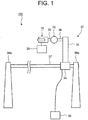
- FIG. 1 is a side view illustrating the configuration of a three-dimensional surface potential distribution measurement system according to an embodiment.
- a three-dimensional surface potential distribution measurement system 100 includes a measurement device 70 ( FIG. 2 ), a three-dimensional motion-driver 30, and a driving controller 50.
- FIG. 2 is a longitudinal sectional view illustrating the configuration of the measurement device of the three-dimensional surface potential distribution measurement system according to the embodiment.
- the measurement device 70 includes a measurement device main body 10 and a computing device 20.
- the measurement device main body 10 includes a Pockels crystal 11, a laser light source 13, a dielectric mirror (hereinafter, referred to merely as “mirror") 14, a polarization beam splitter (hereinafter, abbreviated as "PBS") 15, a photodetector 16, a wavelength plate 17, and a housing 31 that holds the above components.
- the measurement device main body 10 has a gap sensor 40.
- the gap sensor 40 is disposed for preventing the Pockels crystal 11 from contacting a measurement object 5 and configured to measure a gap between the Pockels crystal 11 and the measurement object 5, and output a measurement result to the driving controller 50.
- the Pockels crystal 11 is an elongated crystal and has a first end surface 11a and a second end surface 11b.
- the Pockels crystal 11 has such a shape that the cross section thereof is linearly reduced from the first end surface 11a side toward the second end surface 11b side.
- the Pockels crystal 11 has a square shape in cross section perpendicular to the axial direction thereof, and the length of each side of the square is linearly reduced in the x-direction.
- the opposing two side surfaces of the four side surfaces of the axially-extending Pockels crystal 11 are parallel to the axial direction, and the remaining two side surfaces are inclined to the axial direction.
- the shape of the Pockels crystal 11 is not limited to this, and it is possible to incline at least one side surface to the axial direction and make the remaining side surfaces parallel to the axial direction so as to axially change the cross-sectional area (cross section).
- the longitudinal direction of the Pockels crystal 11 is referred to as x-direction
- a direction in which the object of measurement is scanned is referred to as y-direction
- a direction (direction toward the near side of the paper surface of FIG. 2 ) perpendicular to the x-direction and y-direction is referred to as z-direction.
- the Pockels crystal 11 is an isotropic crystal belonging to "crystal point group - 43m (4 bar 3 m) or crystal point group 23" producing Pockels effect.
- the "bar” part “ - “ of “4 bar” of the " - 43m (4 bar 3 m) " is a symbol that should be positioned above "4"; however, the " - " cannot be positioned just above "4" for descriptive reasons, so the " - " is described as above.
- the Pockels effect is a phenomenon of birefringence that occurs when an isotropic crystal of a dielectric body is placed in an electric field or when voltage is applied thereto. That is, the refractive index changes depending on the applied voltage, to cause the light intensity to change.
- the Pockels crystal 11 may be a BGO (e.g., Bi 12 GeO 20 ) crystal or the like.
- the Pockels crystal 11 can be sensitized to a component that is parallel to or perpendicular to the propagation direction of light of the external electric field depending on a direction formed by the crystal orientation and the propagation direction of the incident light.
- the former is referred to as longitudinal modulation, and the latter is referred to as transversal modulation.
- the Pockels crystal belonging to "crystal point group - 43m (4 bar 3 m) or crystal point group 23" is a crystal that can be arranged in a longitudinal modulation manner.
- a change in the light intensity is proportional to the integral value of the component parallel to an optical path of the external electric field, i.e., proportional to voltage.
- the Pockels crystal 11 is disposed such that the first end surface 11a thereof faces a side that the laser light enters, and the second end surface 11b thereof faces the measurement object 5 at the time of measurement.
- the laser light source 13 emits laser light in the longitudinal direction (x-direction) of the Pockels crystal 11 from the first end surface 11a.
- the laser light has a wavelength of 532.0 nm, a maximum power of 10 mW, and a diameter of 0.34 mm.
- the wavelength of the laser light is set to 532.0 nm; however, the laser light may have a different wavelength as long as the laser light can be propagated through the Pockels crystal 11 and optical components without being significantly attenuated.
- the laser light is linearly polarized.
- the polarization plane of the linearly polarized light is parallel to the incident direction (x-direction) and a direction (z-direction) perpendicular to the scanning direction (y-direction) with respect to the measurement object 5.
- the PBS 15 permits only the above-mentioned linearly polarized light to transmit therethrough.
- the PBS 15 has the laser light emitted from the laser light source 13 transmitting in the incident direction (x-direction).
- the wavelength plate 17 is an element related to the phase of cosine function representing the detection light intensity Pout as will be described later.
- the first end surface 11a of the Pockels crystal 11 is grounded, or the first end surface 11a of the Pockels crystal 11 is set at 0 [V] by a power supply device.
- the laser light from the PBS 15 enters the first end surface 11a of the Pockels crystal 11, travels in the Pockels crystal 11, and then reaches the second end surface 11b.
- the second end surface 11b of the Pockels crystal 11 that the surface of the mirror 14 contacts is applied with a voltage under the influence of an electromagnetic field around the measurement object 5.
- the rear surface of the mirror 14 is located spaced apart from the measurement object 5 by a predetermined distance.
- the predetermined distance is set in consideration of factors such as degree of irregularity of resin on the surface of the measurement object 5 and spatial resolution.
- the mirror 14 is disposed so as to be attached firmly to the second end surface 11b of the Pockels crystal 11.
- the mirror 14 reflects the laser light traveling in the Pockels crystal 11 and reaching the second end surface 11b, in a direction opposite to the x-direction.
- the light intensity of the laser light reflected by the mirror 14 corresponds to an output voltage V which is a potential difference between the first end surface 11a and the second end surface 11b of the Pockels crystal 11.
- the PBS 15 receives the laser light reflected by the mirror 14 and bends the traveling direction thereof 90 degrees, or in a direction opposite to the y-direction.
- the photodetector 16 has a band following a high-frequency component.
- the photodetector 16 is disposed in the longitudinal direction y (more specifically, in the present embodiment, the opposite direction to the longitudinal direction y) with respect to the PBS 15.
- the photodetector 16 receives the laser light whose traveling direction has been changed by the PBS 15.
- the photodetector 16 detects a detection light intensity Pout as the light intensity of the laser light.
- the wavelength plate 17 is an element related to the phase of cosine function representing the detection light intensity Pout as described later.
- the detection light intensity Pout corresponds to the output voltage V which is a potential difference between the first end surface 11a and the second end surface 11b of the Pockels crystal 11.
- Pin is an incident light intensity of the Pockels crystal 11
- V ⁇ is a half wavelength voltage
- ⁇ 0 is a phase difference (arbitrary value) provided by the wavelength plate 17.
- the output voltage V of the Pockels crystal 11 is computed based on the detection light intensity Pout and according to an inverse function of the above cosine function.
- the Pockels crystal 11 As the Pockels crystal 11, a comparatively long crystal of 100 mm is used, so that disturbance of the electric field distribution on the surface of the dielectric body due to approach of the Pockels crystal 11 is small. Therefore, the output voltage V of the Pockels crystal 11 is proportional to the surface potential of the measurement object 5.
- the computing device 20 is a computer connected to the photodetector 16 and an output device 25.
- the computing device 20 includes a CPU (Central Processing Unit) 20a and a storage device 24.
- CPU Central Processing Unit
- the storage device 24 stores a computer program.
- the CPU 20a reads out the computer program from the storage device 24 and executes the computer program.
- the computing device 20 includes, as functional blocks of the CPU 20a, a computing unit 21, a voltage calibration database 22, and a surface potential measurement database 23.
- the computing device 20 is connected to the output device 25 and outputs a computing result to the output device 25.
- the following describes an operation of the measurement device 70 of the three-dimensional surface potential distribution measurement system 100 according to the present embodiment.
- the measurement device 70 performs voltage calibration processing to be described later before execution of a test, and then performs surface potential measurement processing to be described later during the test.
- the computing unit 21 constructs the voltage calibration database 22 through the voltage calibration processing, and refers to the voltage calibration database 22 during the surface potential measurement processing. To the computing unit 21, the voltage calibration processing or surface potential measurement processing is set by, e.g., an input operation of an operator.
- the three-dimensional motion-driver 30 includes a direction-changing rotation driver 32, a radial direction driver 33, a circumferential direction driver 34, a center shaft 37, and center shaft supports 38a and 38b.
- the circumferential direction driver 34 is mounted to the center shaft 37 so as to be rotatable around and axially movable along the center shaft 37.
- the radial direction driver 33 is fixed and supported to the circumferential direction driver 34, and the peripheral angle and axial position of the radial direction driver 33 is determined by the motion of the circumferential direction driver 34.
- the direction-changing rotation driver 32 is supported by the radial direction driver 33 through an axial direction arm 36.
- the radial direction driver 33 can radially move a support part of the axial direction arm 36.
- the radial movement can be achieved by using a rack and pinion mechanism.
- the direction-changing rotation driver 32 supports the housing 31 that holds the measurement device main body 10 through a rotation driver arm 35.
- the three-dimensional motion-driver 30 so as to control the position and posture of the three-dimensional motion-driver 30 computes a changing operation amount from the current position of each of the above units of the three-dimensional motion-driver 30 so as to control the position and posture of the three-dimensional motion-driver 30 such that the Pockels crystal 11 of the measurement device main body 10 faces the target portion with an appropriate gap therefrom.
- the three-dimensional motion-driver 30 so as to control the position and posture of the three-dimensional motion-driver 30 sequentially outputs the computing results as operation command to the units thereof.
- the driving controller 50 uses a signal from the gap sensor 40 as a feedback signal and controls the three-dimensional motion-driver 30 such that the value of the signal is set to a predetermined gap value .
- the predetermined value is set in consideration of the measurement sensitivity of the measurement device main body 10, a surface condition of the measurement object 5, and the like.
- the measurement device main body 10 can be three-dimensionally moved by the thus configured three-dimensional motion-driver 30.
- the following describes a case where the three-dimensional surface potential distribution measurement system 100 is used for measuring the surface potential distribution of a stator coil conductor 3 ( FIG. 5 ) of a stator 1 ( FIG. 5 ) of a rotating electrical machine.
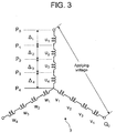
- FIG. 3 is a circuit diagram illustrating a configuration example of stator windings of a rotating electrical machine.
- a high-frequency test voltage or a pulse voltage is applied between a U-phase coil entrance P 0 and a V-phase coil entrance Q 0 of a three-phase stator coil conductor 3, and the potential distribution of the U-phase stator coil conductor 3 is measured.
- the U-phase is constituted of four series-connected coils u 1 , u 2 , u 3 , and u 4
- potential differences ⁇ 1 , ⁇ 2 , ⁇ 3 , and ⁇ 4 applied respectively to the u 1 , u 2 , u 3 , and u 4 are measured.
- Each coil is housed in slots 2a formed in a stator core 2 ( FIG. 5 ). Thus, it is necessary to measure the potential at the coil entrance P 0 and points P 1 , P 2 , P 3 , and P 4 between coils.
- FIG. 4 is a developed view of a part of the circumferential direction, which illustrates a connection example of the stator windings of the rotating electrical machine.
- the coils u 1 , u 2 , and u 3 of the U-phase coil are illustrated.
- the surface potential is measured at the coil entrance P 0 and points P 1 , P 2 , and P 3 between coils which are axially outer portions of the stator core 2.
- the coil u 1 and the coil u 2 are connected at a connection part 4a.
- the coil u 2 and the coil u 3 are connected at a connection part 4b.
- the coil u 3 and the coil u 4 are connected at a connection part 4c.
- connection parts 4a, 4b, and 4c two stator coil conductors 3 overlap each other, and an insulating coating impregnated with resin is wound around each connection part.
- the degree of overlap of the two stator coil conductors at each connection part differs from place to place, and thus, the connection part is not appropriate as the measurement point of the surface potential.
- FIG. 5 is a perspective view for explaining requirements for measurement of the potential distribution on the stator windings of the rotating electrical machine. As illustrated in FIG. 5 , a part of the stator coil conductor 3 outside the slot 2a of the stator core 2, except the connection part 4, is needed to be measured, with the second end surface 11b of the Pockels crystal 11 spaced apart from the insulated surface of the stator coil conductor 3 by a predetermined distance for measurement.
- the measurement device main body 10 of the three-dimensional surface potential distribution measurement system 100 it is necessary to allow the measurement device main body 10 of the three-dimensional surface potential distribution measurement system 100 to face the stator coil conductor 3 which is the measurement object 5 in all of the following directions: a direction from axially outside (negative z-axis direction) toward axially inside; a direction from radially inside toward radially outside; and a direction from radially outside toward radially inside.
- FIG. 6 is a side view illustrating a first state of the three-dimensional motion-driver during measurement of the potential distribution on the stator windings of the rotating electrical machine.
- the direction-changing rotation driver 32 assumes a rotation position such that the rotation driver arm 35 and the axial direction arm 36 are linearly aligned.
- the radial direction driver 33 sets the axial direction arm 36 to a radial position corresponding to the radial position of the stator coil conductor 3.
- the circumferential direction driver 34 sets the axial position thereof to an appropriate position.
- the measurement device main body 10 is set to a position at which it can measure the stator coil conductor 3 from the axially outside thereof.
- FIG. 7 is a side view illustrating a second state of the three-dimensional motion-driver during measurement of the potential distribution on the stator windings of the rotating electrical machine.
- the direction-changing rotation driver 32 assumes a rotation position such that the axial direction arm 36 is parallel to the axial direction and that the rotation driver arm 35 is directed toward the axial center.
- the radial direction driver 33 sets the axial direction arm 36 to a radial position outside the radial position of the stator coil conductor 3.
- the circumferential direction driver 34 sets the axial position thereof to an appropriate position.
- the measurement device main body 10 is set to a position at which it can measure the stator coil conductor 3 from the axially outside thereof.
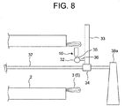
- FIG. 8 is a side view illustrating a third state of the three-dimensional motion-driver during measurement of the potential distribution on the stator windings of the rotating electrical machine.
- the direction-changing rotation driver 32 assumes a rotation position such that the axial direction arm 36 is parallel to the axial direction and that the rotation driver arm 35 is directed outward from the axial center.
- the axial direction arm 36 is set to an appropriate position by the radial direction driver 33, and the circumferential direction driver 34 sets the axial position thereof to an appropriate position.
- the measurement device main body 10 is set to a position at which it can measure the stator coil conductor 3 from the axially inside thereof.
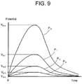
- FIG. 9 is a graph illustrating an example of measurement results of the potential on the stator windings of the rotating electrical machine.
- the horizontal axis represents time, and the vertical axis represents potentials measured at respective measurement points.
- the time bases of the test results are aligned with a time point at which a test pulse voltage is applied as "0".
- FIG. 10 is a graph illustrating an example of a distribution of peak values obtained as measurement result of the potential on the stator windings of the rotating electrical machine .
- Horizontal axis represents positions of P 0 , P 1 , P 2 , P 3 , and P 4 which are the measurement points, and vertical axis represents peak values of potential obtained as measurement results at the respective measurement points in FIG. 9 .
- the potential distribution at measurement points when a test voltage is applied in the test i.e., the potential distribution in the measurement object can be measured.
- a sharing voltage on the surface of a coil of an actual machine after impregnation can be measured in a test where a voltage including a high-frequency component is applied.
- the present invention is not limited to this.
- the present invention may be applied to the case of pre-impregnated type series coils, formed by winding impregnated insulating tapes.
Landscapes
- Physics & Mathematics (AREA)
- General Physics & Mathematics (AREA)
- Electromagnetism (AREA)
- Tests Of Circuit Breakers, Generators, And Electric Motors (AREA)
- Measuring Instrument Details And Bridges, And Automatic Balancing Devices (AREA)
- Measurement Of Current Or Voltage (AREA)
Abstract
Description
- The present invention relates to a three-dimensional surface potential distribution measurement system.
- An inverter drive system that uses an inverter to drive a rotating electrical machine such as an electric motor has been developed and is becoming popular. In such an inverter driver system, the inverter converts a DC voltage into a pulse voltage by switching operation and supplies the pulse voltage to the rotating electrical machine through cables. The rotating electrical machine is driven by the pulse voltage.
- In a system using a series parts in a coil such as a rotating electrical machine coil, sharing voltage of each part on the surface of a coil of an actual machine after impregnation needs to be measured in a non-contact manner since a terminal between both ends of each part of the coil cannot be taken out with conductors. Further, a voltage signal in a high-frequency region is difficult to acquire in measurement using a conventional non-contact surface electrometer.
- Patent Document 1: Japanese Patent Application Laid-Open Publication No.
2013-113637 - Focusing on the voltage distribution of the series coil at start-up, when the rise of a voltage of a power feeding line is sufficiently slower than propagation of a voltage in the series coil in the longitudinal direction thereof, the voltage sharing rate is substantially equalized among conductors of the coil. On the other hand, when the rise of a voltage of a feeding line is sufficiently faster than propagation of the voltage in the series coil in the longitudinal direction thereof, following of a voltage on the exit side of the coil is relatively slower than the rise of a voltage on the entrance side of the coil in an upstream side coil closest to the feeding line. Accordingly, the voltage on the coil exit side does not sufficiently rise relative to that on the entrance side. As a result, a potential difference transiently applied to entrance side of the coil becomes large, or the voltage sharing rate of the entrance side increases transiently.
- In particular, an inverter pulse voltage by the inverter drive system rises fast, so that the voltage sharing rate at a part close to the feeding line increases. Thus, it is necessary to take countermeasures against overvoltage. For countermeasures against overvoltage, measurement of a transient voltage distribution at application of the inverter pulse voltage is important.
- A surface electrometer is used in general for measurement of a surface potential. For example, there is known a technique to estimate current-voltage characteristics using a surface potential which is measured by the surface electrometer with a probe brought into contact with or close to an electric field relaxation system. However, the inverter pulse voltage has a high-frequency component of kHz order or more. In this case, the surface electrometer cannot follow the above high-frequency component.
- As a surface potential measuring means that follows the high-frequency component, a method using a Pockels crystal is known (Refer to Patent Document 1).
- On the other hand, when measuring a sharing voltage on the surface of a coil of an actual machine after impregnation in a system using a series coil, e.g., a rotating electrical machine coil, a part of each stator coil conductor near a connection portion is three-dimensionally changed in shape, so that a distance from an object of measurement varies in a method that moves the surface potential measuring means uniformly outside an insulating material. Thus, a condition may differ from place to place, and therefore an identical calibration curve cannot be used.
- An object of the present invention is to allow a system using series parts in a coil to measure a sharing voltage on the surface of a coil of an actual machine after impregnation in a test that applies a voltage including a high-frequency component.
- According to the present invention, there is provided a three-dimensional surface potential distribution measurement system for measuring a surface potential of a measurement object, the system comprising: a laser light source to emit laser light; a Pockels crystal having a first end surface and a second end surface, exhibiting Pockels effect in which a refractive index changes depending on potential difference between the first end surface and the second end surface, disposed such that the first end surface faces a side that the laser light emitted from the laser light source enters while the second end surface faces the measurement object, and extending in a longitudinal direction along a propagation direction of the laser light; a mirror disposed on the second end surface and configured to reflect the laser light incident from the first end surface of the Pockels crystal in a direction opposite to the laser light incident direction; a photodetector having a band following a high-frequency component of an inverter pulse voltage and configured to receive the laser light reflected by the mirror to detect a light intensity of the laser light corresponding to the potential difference between the first end surface and the second end surface of the Pockels crystal; a housing that holds the laser light source, the Pockels crystal, the mirror, and the photodetector while maintaining the relative positional relationship thereamong; a three-dimensional motion-driver capable of three-dimensionally moving the housing; and a driving controller that controls the three-dimensional motion-driver.
- According to the present invention, it is possible to allow a system using series parts in a coil to measure a sharing voltage on the surface of a coil of an actual machine after impregnation in a test that applies a voltage including a high-frequency component.
-
-
FIG. 1 is a side view illustrating the configuration of a three-dimensional surface potential distribution measurement system according to an embodiment. -
FIG. 2 is a longitudinal sectional view illustrating the configuration of the measurement device of the three-dimensional surface potential distribution measurement system according to the embodiment. -
FIG. 3 is a circuit diagram illustrating a configuration example of stator windings of a rotating electrical machine. -
FIG. 4 is a developed view of a part of the circumferential direction, which illustrates a connection example of the stator windings of the rotating electrical machine. -
FIG. 5 is a perspective view for explaining requirements for measurement of the potential distribution on the stator windings of the rotating electrical machine. -
FIG. 6 is a side view illustrating a first state of the three-dimensional motion-driver during measurement of the potential distribution on the stator windings of the rotating electrical machine. -
FIG. 7 is a side view illustrating a second state of the three-dimensional motion-driver during measurement of the potential distribution on the stator windings of the rotating electrical machine. -
FIG. 8 is a side view illustrating a third state of the three-dimensional motion-driver during measurement of the potential distribution on the stator windings of the rotating electrical machine. -
FIG. 9 is a graph illustrating an example of measurement results of the potential on the stator windings of the rotating electrical machine. -
FIG. 10 is a graph illustrating an example of a distribution of peak values obtained as measurement result of the potential on the stator windings of the rotating electrical machine. - Embodiments of a three-dimensional surface potential distribution measurement apparatus according to the present invention will be described with reference to the drawings. Throughout the description, the same reference numerals are given to the same or similar parts, and repeated description will be omitted.
-
FIG. 1 is a side view illustrating the configuration of a three-dimensional surface potential distribution measurement system according to an embodiment. A three-dimensional surface potentialdistribution measurement system 100 includes a measurement device 70 (FIG. 2 ), a three-dimensional motion-driver 30, and adriving controller 50. -
FIG. 2 is a longitudinal sectional view illustrating the configuration of the measurement device of the three-dimensional surface potential distribution measurement system according to the embodiment. Themeasurement device 70 includes a measurement devicemain body 10 and acomputing device 20. - The measurement device
main body 10 includes a Pockelscrystal 11, alaser light source 13, a dielectric mirror (hereinafter, referred to merely as "mirror") 14, a polarization beam splitter (hereinafter, abbreviated as "PBS") 15, aphotodetector 16, awavelength plate 17, and ahousing 31 that holds the above components. The measurement devicemain body 10 has agap sensor 40. Thegap sensor 40 is disposed for preventing the Pockels crystal 11 from contacting ameasurement object 5 and configured to measure a gap between the Pockelscrystal 11 and themeasurement object 5, and output a measurement result to thedriving controller 50. - The Pockels crystal 11 is an elongated crystal and has a
first end surface 11a and asecond end surface 11b. The Pockels crystal 11 has such a shape that the cross section thereof is linearly reduced from thefirst end surface 11a side toward thesecond end surface 11b side. In the present embodiment, the Pockelscrystal 11 has a square shape in cross section perpendicular to the axial direction thereof, and the length of each side of the square is linearly reduced in the x-direction. - The opposing two side surfaces of the four side surfaces of the axially-extending
Pockels crystal 11 are parallel to the axial direction, and the remaining two side surfaces are inclined to the axial direction. However, the shape of the Pockelscrystal 11 is not limited to this, and it is possible to incline at least one side surface to the axial direction and make the remaining side surfaces parallel to the axial direction so as to axially change the cross-sectional area (cross section). - As illustrated in
FIG. 2 , the longitudinal direction of the Pockelscrystal 11 is referred to as x-direction, a direction in which the object of measurement is scanned is referred to as y-direction, and a direction (direction toward the near side of the paper surface ofFIG. 2 ) perpendicular to the x-direction and y-direction is referred to as z-direction. - The Pockels
crystal 11 is an isotropic crystal belonging to "crystal point group-43m (4 bar 3 m) orcrystal point group 23" producing Pockels effect. The "bar" part "-" of "4 bar" of the "-43m (4 bar 3 m) " is a symbol that should be positioned above "4"; however, the "-" cannot be positioned just above "4" for descriptive reasons, so the "-" is described as above. - The Pockels effect is a phenomenon of birefringence that occurs when an isotropic crystal of a dielectric body is placed in an electric field or when voltage is applied thereto. That is, the refractive index changes depending on the applied voltage, to cause the light intensity to change. The Pockels crystal 11 may be a BGO (e.g., Bi12GeO20) crystal or the like.
- The
Pockels crystal 11 can be sensitized to a component that is parallel to or perpendicular to the propagation direction of light of the external electric field depending on a direction formed by the crystal orientation and the propagation direction of the incident light. The former is referred to as longitudinal modulation, and the latter is referred to as transversal modulation. - The Pockels crystal belonging to "crystal point group-43m (4 bar 3 m) or
crystal point group 23" is a crystal that can be arranged in a longitudinal modulation manner. In the case of the longitudinal modulation arrangement, a change in the light intensity is proportional to the integral value of the component parallel to an optical path of the external electric field, i.e., proportional to voltage. - The
Pockels crystal 11 is disposed such that thefirst end surface 11a thereof faces a side that the laser light enters, and thesecond end surface 11b thereof faces themeasurement object 5 at the time of measurement. - The
laser light source 13 emits laser light in the longitudinal direction (x-direction) of thePockels crystal 11 from thefirst end surface 11a. For example, the laser light has a wavelength of 532.0 nm, a maximum power of 10 mW, and a diameter of 0.34 mm. In this case, the wavelength of the laser light is set to 532.0 nm; however, the laser light may have a different wavelength as long as the laser light can be propagated through thePockels crystal 11 and optical components without being significantly attenuated. - The laser light is linearly polarized. The polarization plane of the linearly polarized light is parallel to the incident direction (x-direction) and a direction (z-direction) perpendicular to the scanning direction (y-direction) with respect to the
measurement object 5. - The
PBS 15 permits only the above-mentioned linearly polarized light to transmit therethrough. ThePBS 15 has the laser light emitted from thelaser light source 13 transmitting in the incident direction (x-direction). Thewavelength plate 17 is an element related to the phase of cosine function representing the detection light intensity Pout as will be described later. - The
first end surface 11a of thePockels crystal 11 is grounded, or thefirst end surface 11a of thePockels crystal 11 is set at 0 [V] by a power supply device. - The laser light from the
PBS 15 enters thefirst end surface 11a of thePockels crystal 11, travels in thePockels crystal 11, and then reaches thesecond end surface 11b. - In a measurement state, the
second end surface 11b of thePockels crystal 11 that the surface of themirror 14 contacts is applied with a voltage under the influence of an electromagnetic field around themeasurement object 5. - The rear surface of the
mirror 14 is located spaced apart from themeasurement object 5 by a predetermined distance. The predetermined distance is set in consideration of factors such as degree of irregularity of resin on the surface of themeasurement object 5 and spatial resolution. - The
mirror 14 is disposed so as to be attached firmly to thesecond end surface 11b of thePockels crystal 11. Themirror 14 reflects the laser light traveling in thePockels crystal 11 and reaching thesecond end surface 11b, in a direction opposite to the x-direction. - The light intensity of the laser light reflected by the
mirror 14 corresponds to an output voltage V which is a potential difference between thefirst end surface 11a and thesecond end surface 11b of thePockels crystal 11. - The
PBS 15 receives the laser light reflected by themirror 14 and bends the traveling direction thereof 90 degrees, or in a direction opposite to the y-direction. - The
photodetector 16 has a band following a high-frequency component. Thephotodetector 16 is disposed in the longitudinal direction y (more specifically, in the present embodiment, the opposite direction to the longitudinal direction y) with respect to thePBS 15. Thephotodetector 16 receives the laser light whose traveling direction has been changed by thePBS 15. Thephotodetector 16 detects a detection light intensity Pout as the light intensity of the laser light. Thewavelength plate 17 is an element related to the phase of cosine function representing the detection light intensity Pout as described later. - The detection light intensity Pout corresponds to the output voltage V which is a potential difference between the
first end surface 11a and thesecond end surface 11b of thePockels crystal 11. The detection light intensity Pout is represented by the following expression as a cosine function of the output voltage V:
- In the cosine function, Pin is an incident light intensity of the
Pockels crystal 11, Vπ is a half wavelength voltage, and θ0 is a phase difference (arbitrary value) provided by thewavelength plate 17. In the present embodiment, the output voltage V of thePockels crystal 11 is computed based on the detection light intensity Pout and according to an inverse function of the above cosine function. - As the
Pockels crystal 11, a comparatively long crystal of 100 mm is used, so that disturbance of the electric field distribution on the surface of the dielectric body due to approach of thePockels crystal 11 is small. Therefore, the output voltage V of thePockels crystal 11 is proportional to the surface potential of themeasurement object 5. - The
computing device 20 is a computer connected to thephotodetector 16 and anoutput device 25. Thecomputing device 20 includes a CPU (Central Processing Unit) 20a and astorage device 24. - The
storage device 24 stores a computer program. TheCPU 20a reads out the computer program from thestorage device 24 and executes the computer program. As theoutput device 25, a display and a printer can be exemplified. - The
computing device 20 includes, as functional blocks of theCPU 20a, acomputing unit 21, avoltage calibration database 22, and a surfacepotential measurement database 23. Thecomputing device 20 is connected to theoutput device 25 and outputs a computing result to theoutput device 25. - The following describes an operation of the
measurement device 70 of the three-dimensional surface potentialdistribution measurement system 100 according to the present embodiment. - The
measurement device 70 performs voltage calibration processing to be described later before execution of a test, and then performs surface potential measurement processing to be described later during the test. Thecomputing unit 21 constructs thevoltage calibration database 22 through the voltage calibration processing, and refers to thevoltage calibration database 22 during the surface potential measurement processing. To thecomputing unit 21, the voltage calibration processing or surface potential measurement processing is set by, e.g., an input operation of an operator. - As illustrated in
FIG. 1 , the three-dimensional motion-driver 30 includes a direction-changingrotation driver 32, aradial direction driver 33, acircumferential direction driver 34, acenter shaft 37, and center shaft supports 38a and 38b. - Both ends of the
center shaft 37 are supported and fixed to the center shaft supports 38a and 38b. Thecircumferential direction driver 34 is mounted to thecenter shaft 37 so as to be rotatable around and axially movable along thecenter shaft 37. Theradial direction driver 33 is fixed and supported to thecircumferential direction driver 34, and the peripheral angle and axial position of theradial direction driver 33 is determined by the motion of thecircumferential direction driver 34. - The direction-changing
rotation driver 32 is supported by theradial direction driver 33 through anaxial direction arm 36. Theradial direction driver 33 can radially move a support part of theaxial direction arm 36. The radial movement can be achieved by using a rack and pinion mechanism. The direction-changingrotation driver 32 supports thehousing 31 that holds the measurement devicemain body 10 through arotation driver arm 35. - When a target portion of the
measurement object 5 is specified, the three-dimensional motion-driver 30 so as to control the position and posture of the three-dimensional motion-driver 30 computes a changing operation amount from the current position of each of the above units of the three-dimensional motion-driver 30 so as to control the position and posture of the three-dimensional motion-driver 30 such that thePockels crystal 11 of the measurement devicemain body 10 faces the target portion with an appropriate gap therefrom. The three-dimensional motion-driver 30 so as to control the position and posture of the three-dimensional motion-driver 30 sequentially outputs the computing results as operation command to the units thereof. - When the
Pockels crystal 11 reaches a position facing the target portion of themeasurement object 5, the drivingcontroller 50 uses a signal from thegap sensor 40 as a feedback signal and controls the three-dimensional motion-driver 30 such that the value of the signal is set to a predetermined gap value . The predetermined value is set in consideration of the measurement sensitivity of the measurement devicemain body 10, a surface condition of themeasurement object 5, and the like. - The measurement device
main body 10 can be three-dimensionally moved by the thus configured three-dimensional motion-driver 30. - The following describes a case where the three-dimensional surface potential
distribution measurement system 100 is used for measuring the surface potential distribution of a stator coil conductor 3 (FIG. 5 ) of a stator 1 (FIG. 5 ) of a rotating electrical machine. -
FIG. 3 is a circuit diagram illustrating a configuration example of stator windings of a rotating electrical machine. A high-frequency test voltage or a pulse voltage is applied between a U-phase coil entrance P0 and a V-phase coil entrance Q0 of a three-phasestator coil conductor 3, and the potential distribution of the U-phasestator coil conductor 3 is measured. When the U-phase is constituted of four series-connected coils u1, u2, u3, and u4, potential differences Δ1, Δ2, Δ3, and Δ4 applied respectively to the u1, u2, u3, and u4 are measured. - Each coil is housed in
slots 2a formed in a stator core 2 (FIG. 5 ). Thus, it is necessary to measure the potential at the coil entrance P0 and points P1, P2, P3, and P4 between coils. -
FIG. 4 is a developed view of a part of the circumferential direction, which illustrates a connection example of the stator windings of the rotating electrical machine. InFIG. 4 , the coils u1, u2, and u3 of the U-phase coil are illustrated. In this example, the surface potential is measured at the coil entrance P0 and points P1, P2, and P3 between coils which are axially outer portions of thestator core 2. - The coil u1 and the coil u2 are connected at a
connection part 4a. The coil u2 and the coil u3 are connected at aconnection part 4b. The coil u3 and the coil u4 are connected at aconnection part 4c. - At each of the
connection parts stator coil conductors 3 overlap each other, and an insulating coating impregnated with resin is wound around each connection part. The degree of overlap of the two stator coil conductors at each connection part differs from place to place, and thus, the connection part is not appropriate as the measurement point of the surface potential. - Therefore, it is necessary to set the position and posture of the measurement device
main body 10 to a direction appropriate for measurement of the surface potential at each point. -
FIG. 5 is a perspective view for explaining requirements for measurement of the potential distribution on the stator windings of the rotating electrical machine. As illustrated inFIG. 5 , a part of thestator coil conductor 3 outside theslot 2a of thestator core 2, except theconnection part 4, is needed to be measured, with thesecond end surface 11b of thePockels crystal 11 spaced apart from the insulated surface of thestator coil conductor 3 by a predetermined distance for measurement. - For this purpose, it is necessary to allow the measurement device
main body 10 of the three-dimensional surface potentialdistribution measurement system 100 to face thestator coil conductor 3 which is themeasurement object 5 in all of the following directions: a direction from axially outside (negative z-axis direction) toward axially inside; a direction from radially inside toward radially outside; and a direction from radially outside toward radially inside. -
FIG. 6 is a side view illustrating a first state of the three-dimensional motion-driver during measurement of the potential distribution on the stator windings of the rotating electrical machine. The direction-changingrotation driver 32 assumes a rotation position such that therotation driver arm 35 and theaxial direction arm 36 are linearly aligned. Theradial direction driver 33 sets theaxial direction arm 36 to a radial position corresponding to the radial position of thestator coil conductor 3. Thecircumferential direction driver 34 sets the axial position thereof to an appropriate position. As a result, the measurement devicemain body 10 is set to a position at which it can measure thestator coil conductor 3 from the axially outside thereof. -
FIG. 7 is a side view illustrating a second state of the three-dimensional motion-driver during measurement of the potential distribution on the stator windings of the rotating electrical machine. The direction-changingrotation driver 32 assumes a rotation position such that theaxial direction arm 36 is parallel to the axial direction and that therotation driver arm 35 is directed toward the axial center. Theradial direction driver 33 sets theaxial direction arm 36 to a radial position outside the radial position of thestator coil conductor 3. Thecircumferential direction driver 34 sets the axial position thereof to an appropriate position. As a result, the measurement devicemain body 10 is set to a position at which it can measure thestator coil conductor 3 from the axially outside thereof. -
FIG. 8 is a side view illustrating a third state of the three-dimensional motion-driver during measurement of the potential distribution on the stator windings of the rotating electrical machine. The direction-changingrotation driver 32 assumes a rotation position such that theaxial direction arm 36 is parallel to the axial direction and that therotation driver arm 35 is directed outward from the axial center. Theaxial direction arm 36 is set to an appropriate position by theradial direction driver 33, and thecircumferential direction driver 34 sets the axial position thereof to an appropriate position. As a result, the measurement devicemain body 10 is set to a position at which it can measure thestator coil conductor 3 from the axially inside thereof. -
FIG. 9 is a graph illustrating an example of measurement results of the potential on the stator windings of the rotating electrical machine. The horizontal axis represents time, and the vertical axis represents potentials measured at respective measurement points. The time bases of the test results are aligned with a time point at which a test pulse voltage is applied as "0". -
FIG. 10 is a graph illustrating an example of a distribution of peak values obtained as measurement result of the potential on the stator windings of the rotating electrical machine . Horizontal axis represents positions of P0, P1, P2, P3, and P4 which are the measurement points, and vertical axis represents peak values of potential obtained as measurement results at the respective measurement points inFIG. 9 . In this manner, the potential distribution at measurement points when a test voltage is applied in the test, i.e., the potential distribution in the measurement object can be measured. - As described above, in a system using a series coil, a sharing voltage on the surface of a coil of an actual machine after impregnation can be measured in a test where a voltage including a high-frequency component is applied.
- While the embodiments of the present invention have been described, those embodiments are presented by way of example only and not intended to limit the scope of the invention. Furthermore, the above-described embodiments may be put to use in various different ways and, if appropriate, any of the components thereof may be omitted, replaced or altered in various different ways without departing from the spirit and scope of the invention.
- For example, what has been described in the embodiment is the case of the series impregnated coils, the present invention is not limited to this. For example, the present invention may be applied to the case of pre-impregnated type series coils, formed by winding impregnated insulating tapes.
- All the above-described embodiments and the modifications made to them are within the spirit and scope of the present invention, which is specifically defined by the appended claims, as well as their equivalents.
-
- 1: stator, 2: stator core, 2a: slot, 3: stator coil conductor, 4, 4a, 4b, 4c: connection part, 5: measurement object, 10: measurement device main body, 11: Pockels crystal, 11a: first end surface, 11b: second end surface, 13: laser light source, 14: dielectric mirror, 15: polarization beam splitter (PBS), 16: photo detector, 17: wavelength plate, 20: computing device, 21: computing unit, 22: voltage calibration database, 23: surface potential measurement database, 24: storage device, 25: output device, 30: three-dimensional motion-driver, 31: housing, 32: direction-changing rotation driver, 33: radial direction driver, 34: circumferential direction driver, 35: rotation driver arm, 36: axial direction arm, 37: center shaft, 38a, 38b: center shaft support, 40: gap sensor, 50: driving controller, 70: measurement device, 100: three-dimensional surface potential distribution measurement system
Claims (6)
- A three-dimensional surface potential distribution measurement system for measuring a surface potential of a measurement object, the system comprising:a laser light source to emit laser light;a Pockels crystal having a first end surface and a second end surface, exhibiting Pockels effect in which a refractive index changes depending on potential difference between the first end surface and the second end surface, disposed such that the first end surface faces a side that the laser light emitted from the laser light source enters while the second end surface faces the measurement object, and extending in a longitudinal direction along a propagation direction of the laser light;a mirror disposed on the second end surface and configured to reflect the laser light incident from the first end surface of the Pockels crystal in a direction opposite to the laser light incident direction;a photodetector having a band following a high-frequency component of an inverter pulse voltage and configured to receive the laser light reflected by the mirror to detect a light intensity of the laser light corresponding to the potential difference between the first end surface and the second end surface of the Pockels crystal;a housing that holds the laser light source, the Pockels crystal, the mirror, and the photodetector while maintaining the relative positional relationship thereamong;a three-dimensional motion-driver capable of three-dimensionally moving the housing; anda driving controller that controls the three-dimensional motion-driver.
- The three-dimensional surface potential distribution measurement system according to claim 1, wherein
the measurement object is a stator coil conductor located outside the axial end portion of a stator core of a rotating electrical machine, and
the three-dimensional motion-driver is configured to move the Pockels crystal to a position where the surface of the stator coil conductor can be measured from radially outside, radially inside, and axially outside the stator coil conductor. - The three-dimensional surface potential distribution measurement system according to claim 2, wherein
the three-dimensional motion-driver includes:a center shaft externally fixed to a center axis position of the stator core so as to be immovable;a circumferential direction driver mounted to the center shaft and configured to change the peripheral and axial positions thereof;a radial direction driver mounted to the circumferential direction driver and configured to change the radial position thereof; anda direction-changing rotation driver mounted to the radial direction driver and configured to change the direction of the Pockels crystal. - The three-dimensional surface potential distribution measurement system according to any one of claims 1 to 3, wherein
the housing has a gap sensor configured to be moved integrally with the Pockels crystal and measure a gap between the Pockels crystal and the surface of the measurement object, and
a gap signal output from the gap sensor is input to the driving controller. - The three-dimensional surface potential distribution measurement system according to any one of claims 1 to 4, wherein
the Pockels crystal is formed in a tapered manner from the first end surface toward the second end surface. - The three-dimensional surface potential distribution measurement system according to any one of claims 1 to 5, wherein
the Pockels crystal is a BGO crystal.
Applications Claiming Priority (1)
| Application Number | Priority Date | Filing Date | Title |
|---|---|---|---|
| PCT/JP2016/000643 WO2017138034A1 (en) | 2016-02-08 | 2016-02-08 | Three-dimensional surface potential distribution measurement system |
Publications (3)
| Publication Number | Publication Date |
|---|---|
| EP3415933A1 true EP3415933A1 (en) | 2018-12-19 |
| EP3415933A4 EP3415933A4 (en) | 2019-09-25 |
| EP3415933B1 EP3415933B1 (en) | 2024-08-07 |
Family
ID=59563023
Family Applications (1)
| Application Number | Title | Priority Date | Filing Date |
|---|---|---|---|
| EP16889743.7A Active EP3415933B1 (en) | 2016-02-08 | 2016-02-08 | Three-dimensional surface potential distribution measurement system |
Country Status (7)
| Country | Link |
|---|---|
| US (1) | US11333697B2 (en) |
| EP (1) | EP3415933B1 (en) |
| JP (1) | JP6839663B2 (en) |
| CN (1) | CN108713149B (en) |
| BR (1) | BR112018016078B1 (en) |
| CA (1) | CA3013883C (en) |
| WO (1) | WO2017138034A1 (en) |
Families Citing this family (1)
| Publication number | Priority date | Publication date | Assignee | Title |
|---|---|---|---|---|
| CN113281578B (en) * | 2021-04-27 | 2022-10-11 | 西安理工大学 | Photoelectric integrated constant-humidity surface potential measuring system based on three-axis motion platform |
Family Cites Families (14)
| Publication number | Priority date | Publication date | Assignee | Title |
|---|---|---|---|---|
| DE2530261C2 (en) * | 1974-10-22 | 1986-10-23 | Asea S.p.A., Mailand/Milano | Programming device for a manipulator |
| JPH04213082A (en) * | 1990-10-18 | 1992-08-04 | Mitsubishi Electric Corp | Armature-coil testing apparatus and testing brush holder |
| JPH068174A (en) * | 1992-06-29 | 1994-01-18 | Sumitomo Electric Ind Ltd | Emergency stop control method for manipulator arm |
| SE518982C2 (en) * | 2000-09-04 | 2002-12-17 | Johansson Ab C E | Adjustment of an angular position to a robotic arm |
| CN100473994C (en) * | 2005-07-14 | 2009-04-01 | 中国科学院电子学研究所 | Inductive electrode three-dimensional electric-field sensor |
| CN100535674C (en) * | 2005-08-05 | 2009-09-02 | 中国科学院电子学研究所 | Small three-dimensional electric field sensor |
| JP5164317B2 (en) * | 2005-08-19 | 2013-03-21 | 株式会社日立ハイテクノロジーズ | Inspection / measurement method and inspection / measurement device using electron beam |
| US7577498B2 (en) * | 2005-08-23 | 2009-08-18 | Motoman, Inc. | Apparatus and methods for a robotic beverage server |
| ATE550675T1 (en) * | 2007-05-18 | 2012-04-15 | Imec | JUNCTION PHOTOVOLTAGE METHOD AND DEVICE FOR THE CONTACTLESS DETERMINATION OF THE SURFACE RESISTANCE AND THE LEAKAGE CURRENT OF A SEMICONDUCTOR |
| JP6192890B2 (en) | 2011-11-25 | 2017-09-06 | 東芝三菱電機産業システム株式会社 | Surface potential distribution measuring apparatus and surface potential distribution measuring method |
| CN105102997B (en) * | 2013-03-19 | 2018-06-26 | 东芝三菱电机产业系统株式会社 | Surface potential distribution measuring device |
| JP2015099116A (en) * | 2013-11-20 | 2015-05-28 | セイコーエプソン株式会社 | Component analyzer |
| CN103954850B (en) * | 2014-04-22 | 2017-01-04 | 重庆大学 | Surface charge measuring system that a kind of motion control mechanism is external and measuring method |
| WO2015186160A1 (en) * | 2014-06-06 | 2015-12-10 | 東芝三菱電機産業システム株式会社 | A device for measuring 3d surface potential distribution |
-
2016
- 2016-02-08 EP EP16889743.7A patent/EP3415933B1/en active Active
- 2016-02-08 WO PCT/JP2016/000643 patent/WO2017138034A1/en not_active Ceased
- 2016-02-08 BR BR112018016078-4A patent/BR112018016078B1/en active IP Right Grant
- 2016-02-08 CA CA3013883A patent/CA3013883C/en active Active
- 2016-02-08 JP JP2017566231A patent/JP6839663B2/en active Active
- 2016-02-08 CN CN201680081323.5A patent/CN108713149B/en active Active
-
2018
- 2018-08-08 US US16/058,475 patent/US11333697B2/en active Active
Also Published As
| Publication number | Publication date |
|---|---|
| CN108713149B (en) | 2021-07-06 |
| EP3415933A4 (en) | 2019-09-25 |
| JP6839663B2 (en) | 2021-03-10 |
| CN108713149A (en) | 2018-10-26 |
| CA3013883C (en) | 2022-08-23 |
| US20180348276A1 (en) | 2018-12-06 |
| CA3013883A1 (en) | 2017-08-17 |
| BR112018016078A2 (en) | 2019-05-14 |
| BR112018016078B1 (en) | 2023-05-02 |
| JPWO2017138034A1 (en) | 2018-11-29 |
| WO2017138034A1 (en) | 2017-08-17 |
| EP3415933B1 (en) | 2024-08-07 |
| US11333697B2 (en) | 2022-05-17 |
Similar Documents
| Publication | Publication Date | Title |
|---|---|---|
| EP3153870B1 (en) | A device for measuring 3d surface potential distribution | |
| EP2784526B1 (en) | Surface potential distribution measuring device and surface potential distribution measuring method | |
| CN105102997B (en) | Surface potential distribution measuring device | |
| US11333697B2 (en) | Three-dimensional surface potential distribution measurement system | |
| Kumada et al. | Potential distribution on the stress grading system of high-voltage rotating machines–I measuring system | |
| KR20180115828A (en) | apparatus for measuring direct current using light | |
| KR101028107B1 (en) | Rotation angle measuring system of galvanometer scanner | |
| JP6159857B2 (en) | Surface potential distribution measuring apparatus and surface potential distribution measuring method |
Legal Events
| Date | Code | Title | Description |
|---|---|---|---|
| STAA | Information on the status of an ep patent application or granted ep patent |
Free format text: STATUS: THE INTERNATIONAL PUBLICATION HAS BEEN MADE |
|
| PUAI | Public reference made under article 153(3) epc to a published international application that has entered the european phase |
Free format text: ORIGINAL CODE: 0009012 |
|
| STAA | Information on the status of an ep patent application or granted ep patent |
Free format text: STATUS: REQUEST FOR EXAMINATION WAS MADE |
|
| 17P | Request for examination filed |
Effective date: 20180806 |
|
| AK | Designated contracting states |
Kind code of ref document: A1 Designated state(s): AL AT BE BG CH CY CZ DE DK EE ES FI FR GB GR HR HU IE IS IT LI LT LU LV MC MK MT NL NO PL PT RO RS SE SI SK SM TR |
|
| AX | Request for extension of the european patent |
Extension state: BA ME |
|
| DAV | Request for validation of the european patent (deleted) | ||
| DAX | Request for extension of the european patent (deleted) | ||
| A4 | Supplementary search report drawn up and despatched |
Effective date: 20190823 |
|
| RIC1 | Information provided on ipc code assigned before grant |
Ipc: G01R 29/08 20060101AFI20190819BHEP Ipc: G01R 29/14 20060101ALI20190819BHEP Ipc: G01R 31/34 20060101ALI20190819BHEP Ipc: G01R 15/24 20060101ALI20190819BHEP |
|
| STAA | Information on the status of an ep patent application or granted ep patent |
Free format text: STATUS: EXAMINATION IS IN PROGRESS |
|
| 17Q | First examination report despatched |
Effective date: 20221006 |
|
| GRAP | Despatch of communication of intention to grant a patent |
Free format text: ORIGINAL CODE: EPIDOSNIGR1 |
|
| STAA | Information on the status of an ep patent application or granted ep patent |
Free format text: STATUS: GRANT OF PATENT IS INTENDED |
|
| INTG | Intention to grant announced |
Effective date: 20240306 |
|
| GRAS | Grant fee paid |
Free format text: ORIGINAL CODE: EPIDOSNIGR3 |
|
| GRAA | (expected) grant |
Free format text: ORIGINAL CODE: 0009210 |
|
| STAA | Information on the status of an ep patent application or granted ep patent |
Free format text: STATUS: THE PATENT HAS BEEN GRANTED |
|
| AK | Designated contracting states |
Kind code of ref document: B1 Designated state(s): AL AT BE BG CH CY CZ DE DK EE ES FI FR GB GR HR HU IE IS IT LI LT LU LV MC MK MT NL NO PL PT RO RS SE SI SK SM TR |
|
| RAP3 | Party data changed (applicant data changed or rights of an application transferred) |
Owner name: THE UNIVERSITY OF TOKYO Owner name: TMEIC CORPORATION |
|
| REG | Reference to a national code |
Ref country code: GB Ref legal event code: FG4D |
|
| REG | Reference to a national code |
Ref country code: CH Ref legal event code: EP |
|
| GRAT | Correction requested after decision to grant or after decision to maintain patent in amended form |
Free format text: ORIGINAL CODE: EPIDOSNCDEC |
|
| REG | Reference to a national code |
Ref country code: IE Ref legal event code: FG4D |
|
| REG | Reference to a national code |
Ref country code: DE Ref legal event code: R096 Ref document number: 602016088829 Country of ref document: DE |
|
| GRAM | Information related to correction after decision after decision to grant or to maintain patent in amended form deleted |
Free format text: ORIGINAL CODE: EPIDOSDCDEC |
|
| REG | Reference to a national code |
Ref country code: CH Ref legal event code: PK Free format text: BERICHTIGUNGEN |
|
| REG | Reference to a national code |
Ref country code: SE Ref legal event code: TRGR |
|
| RIN2 | Information on inventor provided after grant (corrected) |
Inventor name: IKEDA, HISATOSHI Inventor name: KUMADA, AKIKO Inventor name: HIDAKA, KUNIHIKO Inventor name: TSUBOI, YUICHI Inventor name: YOSHIMITSU, TETSUO Inventor name: FURUKAWA, MASAAKI |
|
| REG | Reference to a national code |
Ref country code: LT Ref legal event code: MG9D |
|
| REG | Reference to a national code |
Ref country code: NL Ref legal event code: MP Effective date: 20240807 |
|
| PG25 | Lapsed in a contracting state [announced via postgrant information from national office to epo] |
Ref country code: NO Free format text: LAPSE BECAUSE OF FAILURE TO SUBMIT A TRANSLATION OF THE DESCRIPTION OR TO PAY THE FEE WITHIN THE PRESCRIBED TIME-LIMIT Effective date: 20241107 |
|
| REG | Reference to a national code |
Ref country code: AT Ref legal event code: MK05 Ref document number: 1711512 Country of ref document: AT Kind code of ref document: T Effective date: 20240807 |
|
| PG25 | Lapsed in a contracting state [announced via postgrant information from national office to epo] |
Ref country code: FI Free format text: LAPSE BECAUSE OF FAILURE TO SUBMIT A TRANSLATION OF THE DESCRIPTION OR TO PAY THE FEE WITHIN THE PRESCRIBED TIME-LIMIT Effective date: 20240807 Ref country code: NL Free format text: LAPSE BECAUSE OF FAILURE TO SUBMIT A TRANSLATION OF THE DESCRIPTION OR TO PAY THE FEE WITHIN THE PRESCRIBED TIME-LIMIT Effective date: 20240807 Ref country code: GR Free format text: LAPSE BECAUSE OF FAILURE TO SUBMIT A TRANSLATION OF THE DESCRIPTION OR TO PAY THE FEE WITHIN THE PRESCRIBED TIME-LIMIT Effective date: 20241108 Ref country code: PL Free format text: LAPSE BECAUSE OF FAILURE TO SUBMIT A TRANSLATION OF THE DESCRIPTION OR TO PAY THE FEE WITHIN THE PRESCRIBED TIME-LIMIT Effective date: 20240807 Ref country code: PT Free format text: LAPSE BECAUSE OF FAILURE TO SUBMIT A TRANSLATION OF THE DESCRIPTION OR TO PAY THE FEE WITHIN THE PRESCRIBED TIME-LIMIT Effective date: 20241209 |
|
| PG25 | Lapsed in a contracting state [announced via postgrant information from national office to epo] |
Ref country code: BG Free format text: LAPSE BECAUSE OF FAILURE TO SUBMIT A TRANSLATION OF THE DESCRIPTION OR TO PAY THE FEE WITHIN THE PRESCRIBED TIME-LIMIT Effective date: 20240807 |
|
| PG25 | Lapsed in a contracting state [announced via postgrant information from national office to epo] |
Ref country code: LV Free format text: LAPSE BECAUSE OF FAILURE TO SUBMIT A TRANSLATION OF THE DESCRIPTION OR TO PAY THE FEE WITHIN THE PRESCRIBED TIME-LIMIT Effective date: 20240807 |
|
| PG25 | Lapsed in a contracting state [announced via postgrant information from national office to epo] |
Ref country code: AT Free format text: LAPSE BECAUSE OF FAILURE TO SUBMIT A TRANSLATION OF THE DESCRIPTION OR TO PAY THE FEE WITHIN THE PRESCRIBED TIME-LIMIT Effective date: 20240807 Ref country code: IS Free format text: LAPSE BECAUSE OF FAILURE TO SUBMIT A TRANSLATION OF THE DESCRIPTION OR TO PAY THE FEE WITHIN THE PRESCRIBED TIME-LIMIT Effective date: 20241207 |
|
| PG25 | Lapsed in a contracting state [announced via postgrant information from national office to epo] |
Ref country code: HR Free format text: LAPSE BECAUSE OF FAILURE TO SUBMIT A TRANSLATION OF THE DESCRIPTION OR TO PAY THE FEE WITHIN THE PRESCRIBED TIME-LIMIT Effective date: 20240807 |
|
| PG25 | Lapsed in a contracting state [announced via postgrant information from national office to epo] |
Ref country code: ES Free format text: LAPSE BECAUSE OF FAILURE TO SUBMIT A TRANSLATION OF THE DESCRIPTION OR TO PAY THE FEE WITHIN THE PRESCRIBED TIME-LIMIT Effective date: 20240807 Ref country code: RS Free format text: LAPSE BECAUSE OF FAILURE TO SUBMIT A TRANSLATION OF THE DESCRIPTION OR TO PAY THE FEE WITHIN THE PRESCRIBED TIME-LIMIT Effective date: 20241107 |
|
| PG25 | Lapsed in a contracting state [announced via postgrant information from national office to epo] |
Ref country code: RS Free format text: LAPSE BECAUSE OF FAILURE TO SUBMIT A TRANSLATION OF THE DESCRIPTION OR TO PAY THE FEE WITHIN THE PRESCRIBED TIME-LIMIT Effective date: 20241107 Ref country code: PT Free format text: LAPSE BECAUSE OF FAILURE TO SUBMIT A TRANSLATION OF THE DESCRIPTION OR TO PAY THE FEE WITHIN THE PRESCRIBED TIME-LIMIT Effective date: 20241209 Ref country code: PL Free format text: LAPSE BECAUSE OF FAILURE TO SUBMIT A TRANSLATION OF THE DESCRIPTION OR TO PAY THE FEE WITHIN THE PRESCRIBED TIME-LIMIT Effective date: 20240807 Ref country code: NO Free format text: LAPSE BECAUSE OF FAILURE TO SUBMIT A TRANSLATION OF THE DESCRIPTION OR TO PAY THE FEE WITHIN THE PRESCRIBED TIME-LIMIT Effective date: 20241107 Ref country code: NL Free format text: LAPSE BECAUSE OF FAILURE TO SUBMIT A TRANSLATION OF THE DESCRIPTION OR TO PAY THE FEE WITHIN THE PRESCRIBED TIME-LIMIT Effective date: 20240807 Ref country code: LV Free format text: LAPSE BECAUSE OF FAILURE TO SUBMIT A TRANSLATION OF THE DESCRIPTION OR TO PAY THE FEE WITHIN THE PRESCRIBED TIME-LIMIT Effective date: 20240807 Ref country code: IS Free format text: LAPSE BECAUSE OF FAILURE TO SUBMIT A TRANSLATION OF THE DESCRIPTION OR TO PAY THE FEE WITHIN THE PRESCRIBED TIME-LIMIT Effective date: 20241207 Ref country code: HR Free format text: LAPSE BECAUSE OF FAILURE TO SUBMIT A TRANSLATION OF THE DESCRIPTION OR TO PAY THE FEE WITHIN THE PRESCRIBED TIME-LIMIT Effective date: 20240807 Ref country code: GR Free format text: LAPSE BECAUSE OF FAILURE TO SUBMIT A TRANSLATION OF THE DESCRIPTION OR TO PAY THE FEE WITHIN THE PRESCRIBED TIME-LIMIT Effective date: 20241108 Ref country code: FI Free format text: LAPSE BECAUSE OF FAILURE TO SUBMIT A TRANSLATION OF THE DESCRIPTION OR TO PAY THE FEE WITHIN THE PRESCRIBED TIME-LIMIT Effective date: 20240807 Ref country code: ES Free format text: LAPSE BECAUSE OF FAILURE TO SUBMIT A TRANSLATION OF THE DESCRIPTION OR TO PAY THE FEE WITHIN THE PRESCRIBED TIME-LIMIT Effective date: 20240807 Ref country code: BG Free format text: LAPSE BECAUSE OF FAILURE TO SUBMIT A TRANSLATION OF THE DESCRIPTION OR TO PAY THE FEE WITHIN THE PRESCRIBED TIME-LIMIT Effective date: 20240807 Ref country code: AT Free format text: LAPSE BECAUSE OF FAILURE TO SUBMIT A TRANSLATION OF THE DESCRIPTION OR TO PAY THE FEE WITHIN THE PRESCRIBED TIME-LIMIT Effective date: 20240807 |
|
| PGFP | Annual fee paid to national office [announced via postgrant information from national office to epo] |
Ref country code: DE Payment date: 20250117 Year of fee payment: 10 |
|
| PG25 | Lapsed in a contracting state [announced via postgrant information from national office to epo] |
Ref country code: SM Free format text: LAPSE BECAUSE OF FAILURE TO SUBMIT A TRANSLATION OF THE DESCRIPTION OR TO PAY THE FEE WITHIN THE PRESCRIBED TIME-LIMIT Effective date: 20240807 Ref country code: RO Free format text: LAPSE BECAUSE OF FAILURE TO SUBMIT A TRANSLATION OF THE DESCRIPTION OR TO PAY THE FEE WITHIN THE PRESCRIBED TIME-LIMIT Effective date: 20240807 Ref country code: DK Free format text: LAPSE BECAUSE OF FAILURE TO SUBMIT A TRANSLATION OF THE DESCRIPTION OR TO PAY THE FEE WITHIN THE PRESCRIBED TIME-LIMIT Effective date: 20240807 |
|
| PGFP | Annual fee paid to national office [announced via postgrant information from national office to epo] |
Ref country code: SE Payment date: 20250219 Year of fee payment: 10 |
|
| PG25 | Lapsed in a contracting state [announced via postgrant information from national office to epo] |
Ref country code: EE Free format text: LAPSE BECAUSE OF FAILURE TO SUBMIT A TRANSLATION OF THE DESCRIPTION OR TO PAY THE FEE WITHIN THE PRESCRIBED TIME-LIMIT Effective date: 20240807 |
|
| PG25 | Lapsed in a contracting state [announced via postgrant information from national office to epo] |
Ref country code: CZ Free format text: LAPSE BECAUSE OF FAILURE TO SUBMIT A TRANSLATION OF THE DESCRIPTION OR TO PAY THE FEE WITHIN THE PRESCRIBED TIME-LIMIT Effective date: 20240807 |
|
| PGFP | Annual fee paid to national office [announced via postgrant information from national office to epo] |
Ref country code: FR Payment date: 20250220 Year of fee payment: 10 |
|
| PG25 | Lapsed in a contracting state [announced via postgrant information from national office to epo] |
Ref country code: SK Free format text: LAPSE BECAUSE OF FAILURE TO SUBMIT A TRANSLATION OF THE DESCRIPTION OR TO PAY THE FEE WITHIN THE PRESCRIBED TIME-LIMIT Effective date: 20240807 |
|
| PGFP | Annual fee paid to national office [announced via postgrant information from national office to epo] |
Ref country code: GB Payment date: 20250220 Year of fee payment: 10 |
|
| REG | Reference to a national code |
Ref country code: DE Ref legal event code: R097 Ref document number: 602016088829 Country of ref document: DE |
|
| PLBE | No opposition filed within time limit |
Free format text: ORIGINAL CODE: 0009261 |
|
| STAA | Information on the status of an ep patent application or granted ep patent |
Free format text: STATUS: NO OPPOSITION FILED WITHIN TIME LIMIT |
|
| 26N | No opposition filed |
Effective date: 20250508 |
|
| PG25 | Lapsed in a contracting state [announced via postgrant information from national office to epo] |
Ref country code: MC Free format text: LAPSE BECAUSE OF FAILURE TO SUBMIT A TRANSLATION OF THE DESCRIPTION OR TO PAY THE FEE WITHIN THE PRESCRIBED TIME-LIMIT Effective date: 20240807 |
|
| REG | Reference to a national code |
Ref country code: CH Ref legal event code: PL |
|
| PG25 | Lapsed in a contracting state [announced via postgrant information from national office to epo] |
Ref country code: LU Free format text: LAPSE BECAUSE OF NON-PAYMENT OF DUE FEES Effective date: 20250208 |
|
| PG25 | Lapsed in a contracting state [announced via postgrant information from national office to epo] |
Ref country code: CH Free format text: LAPSE BECAUSE OF NON-PAYMENT OF DUE FEES Effective date: 20250228 |
|
| REG | Reference to a national code |
Ref country code: BE Ref legal event code: MM Effective date: 20250228 |
|
| PG25 | Lapsed in a contracting state [announced via postgrant information from national office to epo] |
Ref country code: BE Free format text: LAPSE BECAUSE OF NON-PAYMENT OF DUE FEES Effective date: 20250228 |
|
| PG25 | Lapsed in a contracting state [announced via postgrant information from national office to epo] |
Ref country code: IE Free format text: LAPSE BECAUSE OF NON-PAYMENT OF DUE FEES Effective date: 20250208 |
|
| PG25 | Lapsed in a contracting state [announced via postgrant information from national office to epo] |
Ref country code: IT Free format text: LAPSE BECAUSE OF FAILURE TO SUBMIT A TRANSLATION OF THE DESCRIPTION OR TO PAY THE FEE WITHIN THE PRESCRIBED TIME-LIMIT Effective date: 20240807 |
|
| PG25 | Lapsed in a contracting state [announced via postgrant information from national office to epo] |
Ref country code: CY Free format text: LAPSE BECAUSE OF FAILURE TO SUBMIT A TRANSLATION OF THE DESCRIPTION OR TO PAY THE FEE WITHIN THE PRESCRIBED TIME-LIMIT Effective date: 20240807 |
|
| PG25 | Lapsed in a contracting state [announced via postgrant information from national office to epo] |
Ref country code: TR Free format text: LAPSE BECAUSE OF FAILURE TO SUBMIT A TRANSLATION OF THE DESCRIPTION OR TO PAY THE FEE WITHIN THE PRESCRIBED TIME-LIMIT Effective date: 20240807 |
|
| PG25 | Lapsed in a contracting state [announced via postgrant information from national office to epo] |
Ref country code: LT Free format text: LAPSE BECAUSE OF FAILURE TO SUBMIT A TRANSLATION OF THE DESCRIPTION OR TO PAY THE FEE WITHIN THE PRESCRIBED TIME-LIMIT Effective date: 20240807 |