EP3415923A1 - Additively manufactured flow measurement sensor - Google Patents
Additively manufactured flow measurement sensor Download PDFInfo
- Publication number
- EP3415923A1 EP3415923A1 EP18176415.0A EP18176415A EP3415923A1 EP 3415923 A1 EP3415923 A1 EP 3415923A1 EP 18176415 A EP18176415 A EP 18176415A EP 3415923 A1 EP3415923 A1 EP 3415923A1
- Authority
- EP
- European Patent Office
- Prior art keywords
- venturi
- cross
- sectional shape
- forming
- segment
- Prior art date
- Legal status (The legal status is an assumption and is not a legal conclusion. Google has not performed a legal analysis and makes no representation as to the accuracy of the status listed.)
- Granted
Links
Images


Classifications
-
- G—PHYSICS
- G01—MEASURING; TESTING
- G01F—MEASURING VOLUME, VOLUME FLOW, MASS FLOW OR LIQUID LEVEL; METERING BY VOLUME
- G01F1/00—Measuring the volume flow or mass flow of fluid or fluent solid material wherein the fluid passes through a meter in a continuous flow
- G01F1/05—Measuring the volume flow or mass flow of fluid or fluent solid material wherein the fluid passes through a meter in a continuous flow by using mechanical effects
- G01F1/34—Measuring the volume flow or mass flow of fluid or fluent solid material wherein the fluid passes through a meter in a continuous flow by using mechanical effects by measuring pressure or differential pressure
- G01F1/36—Measuring the volume flow or mass flow of fluid or fluent solid material wherein the fluid passes through a meter in a continuous flow by using mechanical effects by measuring pressure or differential pressure the pressure or differential pressure being created by the use of flow constriction
- G01F1/40—Details of construction of the flow constriction devices
- G01F1/44—Venturi tubes
-
- B—PERFORMING OPERATIONS; TRANSPORTING
- B29—WORKING OF PLASTICS; WORKING OF SUBSTANCES IN A PLASTIC STATE IN GENERAL
- B29C—SHAPING OR JOINING OF PLASTICS; SHAPING OF MATERIAL IN A PLASTIC STATE, NOT OTHERWISE PROVIDED FOR; AFTER-TREATMENT OF THE SHAPED PRODUCTS, e.g. REPAIRING
- B29C64/00—Additive manufacturing, i.e. manufacturing of three-dimensional [3D] objects by additive deposition, additive agglomeration or additive layering, e.g. by 3D printing, stereolithography or selective laser sintering
-
- B—PERFORMING OPERATIONS; TRANSPORTING
- B33—ADDITIVE MANUFACTURING TECHNOLOGY
- B33Y—ADDITIVE MANUFACTURING, i.e. MANUFACTURING OF THREE-DIMENSIONAL [3D] OBJECTS BY ADDITIVE DEPOSITION, ADDITIVE AGGLOMERATION OR ADDITIVE LAYERING, e.g. BY 3D PRINTING, STEREOLITHOGRAPHY OR SELECTIVE LASER SINTERING
- B33Y10/00—Processes of additive manufacturing
-
- B—PERFORMING OPERATIONS; TRANSPORTING
- B33—ADDITIVE MANUFACTURING TECHNOLOGY
- B33Y—ADDITIVE MANUFACTURING, i.e. MANUFACTURING OF THREE-DIMENSIONAL [3D] OBJECTS BY ADDITIVE DEPOSITION, ADDITIVE AGGLOMERATION OR ADDITIVE LAYERING, e.g. BY 3D PRINTING, STEREOLITHOGRAPHY OR SELECTIVE LASER SINTERING
- B33Y80/00—Products made by additive manufacturing
-
- G—PHYSICS
- G01—MEASURING; TESTING
- G01F—MEASURING VOLUME, VOLUME FLOW, MASS FLOW OR LIQUID LEVEL; METERING BY VOLUME
- G01F1/00—Measuring the volume flow or mass flow of fluid or fluent solid material wherein the fluid passes through a meter in a continuous flow
- G01F1/76—Devices for measuring mass flow of a fluid or a fluent solid material
-
- G—PHYSICS
- G01—MEASURING; TESTING
- G01P—MEASURING LINEAR OR ANGULAR SPEED, ACCELERATION, DECELERATION, OR SHOCK; INDICATING PRESENCE, ABSENCE, OR DIRECTION, OF MOVEMENT
- G01P5/00—Measuring speed of fluids, e.g. of air stream; Measuring speed of bodies relative to fluids, e.g. of ship, of aircraft
- G01P5/14—Measuring speed of fluids, e.g. of air stream; Measuring speed of bodies relative to fluids, e.g. of ship, of aircraft by measuring differences of pressure in the fluid
-
- B—PERFORMING OPERATIONS; TRANSPORTING
- B22—CASTING; POWDER METALLURGY
- B22F—WORKING METALLIC POWDER; MANUFACTURE OF ARTICLES FROM METALLIC POWDER; MAKING METALLIC POWDER; APPARATUS OR DEVICES SPECIALLY ADAPTED FOR METALLIC POWDER
- B22F10/00—Additive manufacturing of workpieces or articles from metallic powder
- B22F10/20—Direct sintering or melting
- B22F10/25—Direct deposition of metal particles, e.g. direct metal deposition [DMD] or laser engineered net shaping [LENS]
-
- B—PERFORMING OPERATIONS; TRANSPORTING
- B22—CASTING; POWDER METALLURGY
- B22F—WORKING METALLIC POWDER; MANUFACTURE OF ARTICLES FROM METALLIC POWDER; MAKING METALLIC POWDER; APPARATUS OR DEVICES SPECIALLY ADAPTED FOR METALLIC POWDER
- B22F10/00—Additive manufacturing of workpieces or articles from metallic powder
- B22F10/20—Direct sintering or melting
- B22F10/28—Powder bed fusion, e.g. selective laser melting [SLM] or electron beam melting [EBM]
-
- B—PERFORMING OPERATIONS; TRANSPORTING
- B22—CASTING; POWDER METALLURGY
- B22F—WORKING METALLIC POWDER; MANUFACTURE OF ARTICLES FROM METALLIC POWDER; MAKING METALLIC POWDER; APPARATUS OR DEVICES SPECIALLY ADAPTED FOR METALLIC POWDER
- B22F5/00—Manufacture of workpieces or articles from metallic powder characterised by the special shape of the product
- B22F5/10—Manufacture of workpieces or articles from metallic powder characterised by the special shape of the product of articles with cavities or holes, not otherwise provided for in the preceding subgroups
- B22F5/106—Tube or ring forms
-
- Y—GENERAL TAGGING OF NEW TECHNOLOGICAL DEVELOPMENTS; GENERAL TAGGING OF CROSS-SECTIONAL TECHNOLOGIES SPANNING OVER SEVERAL SECTIONS OF THE IPC; TECHNICAL SUBJECTS COVERED BY FORMER USPC CROSS-REFERENCE ART COLLECTIONS [XRACs] AND DIGESTS
- Y02—TECHNOLOGIES OR APPLICATIONS FOR MITIGATION OR ADAPTATION AGAINST CLIMATE CHANGE
- Y02P—CLIMATE CHANGE MITIGATION TECHNOLOGIES IN THE PRODUCTION OR PROCESSING OF GOODS
- Y02P10/00—Technologies related to metal processing
- Y02P10/25—Process efficiency
Definitions
- Mass flow measurement sensors are commonly used in aircraft environmental control systems (ECS).
- One type of sensor, a boost venturi sensor includes concentric venturi structures, and may further include one or more electronic pressure sensors that provide fluid flow information to a control unit.
- Current venturi-type sensors are formed from various cast, forged, and machined components that undergo manufacturing processes such as dip brazing or welding to join the multiple components. The venturi sensor is then drilled to create fluid sense lines within the sensor body.
- the accuracy of conventionally-manufactured boost venturi sensors can be negatively impacted by the multiple braze joints and plugged cross-drill points. Further, the cross-section of conventional venturis is limited to what can be achieved by current tooling methods or access to cross-drilling and plugging.
- a flow measurement sensing device includes a first venturi having a first shield portion, an elongated portion connected to an outer surface of the first venturi, and a second venturi housed within the first venturi.
- the second venturi has a second shield portion and at least one air inlet.
- the flow measurement sensing device further includes a first integral passageway extending from the air inlet through the elongated portion.
- the first integral passageway has a first segment with a first cross-sectional shape and a segment with a second cross-sectional shape.
- a method of forming a flow measurement sensing device includes forming a first venturi having a first shield portion, forming an elongated portion extending from the first venturi and having a first integral passageway extending therethrough, and forming a second venturi having a second shield portion within the first venturi.
- the method further includes forming at least one air inlet near the second shield portion of the second venturi.
- the first integral passageway extends from the at least one air inlet through the elongated portion and includes a first segment with a first cross-sectional shape and a second segments with a second cross-sectional shape.
- the fluid passageways are integrally formed with the sensor such that there are no cross-drill points needing to be plugged.
- the main venturi and/or the boost venturi can be formed with various cross-sections to optimize fluid flow through the sensor. Other features can also be added to allow for more accurate flow readings.
- FIG. 1 is a side view of flow measurement sensing device 10.
- Device 10 includes venturi portion 12, elongated portion 14, base portion 16, and pressure sensors 18. Sensors 18 can be mounted to base portion 16, or located within the environmental control system (ECS). Sensors 18 receive fluid flow through external flow lines 20.
- ECS environmental control system
- device 10 can include a plate (not shown) attached to the bottom of base portion 16 to which sensors 18 can be mounted, and which can include mounts to attach device 10 to a surface within the ECS.
- Device 10 can be mounted in an air duct within the ECS in an exemplary embodiment, but can also be placed in a free stream of air (outside of an enclosed structure) to provide flow measurements. Device 10 samples portions of airflow F (indicated by the arrows).
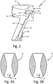
- FIG. 2 is a cross-section of device 10 above base portion 16.
- venturi portion 12 includes main venturi 22, and boost venturi 24 disposed concentrically within main venturi 22.
- Main venturi includes an inner surface 26, and boost venturi 24 includes an inner surface 28.
- Inner surfaces 26, 28 can be smooth, roughened, or can include a combination of smooth and rough portions, based on the application.
- a first passageway 30 extends from venturi air inlet 32 through elongated portion 14.
- a second passageway 34 extends from inlet 36 through elongated portion 14.
- a portion of the airflow through boost venturi 24 enters inlet 32 and flows through passageway 30.
- a portion of airflow around elongated portion 14 enters inlet 36 and flows through passageway 34.
- flow lines 20 FIG. 1
- Pressure sensors 18 can be, for example, differential pressure sensors measuring changes in static and total pressure.
- Passageway 30 is integrally formed with venturi portion 12 and elongated portion 14. Passageway 30 can be formed to include a tapered portion beginning at and in the region adjacent inlet 32.
- FIGS. 3A and 3B are cross-sections of boost venturi 24 at inlet 32.
- the tapered portion can be elliptical ( FIG. 3A ) or rectangular ( FIG. 3B ) in some embodiments.
- the remainder of passageway 30 can have a generally cylindrical cross-section, as is shown in the cross section taken at a mid-point of elongated portion 14, illustrated by FIG. 4 .
- the initially tapered cross-section of passageway 30 allows for a smoother transition of the airflow entering passageway 30 at inlet 32, which increases the accuracy of device 10.
- passageway 30 can have a uniform cross-section (cylindrical, elliptical, rectangular, etc.) based on flow sensing requirements.
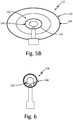
- FIG. 5A is a front view of venturi portion 12, and FIG. 5B is a front view of alternative venturi portion 112 at its upstream side (based on the direction of airflow F in FIG. 1 ).
- Main venturi 22 includes shield 38
- boost venturi 24 includes a similar shield 40.
- shields 38 and 40 have generally circular cross-sections, however, other embodiments of device 10 can include shields having different cross-sections.
- FIG. 5B shows an alternative embodiment in which main venturi 122 and boost venturi 124 have generally oblong shields 138 and 140, respectively.
- shield 38/138 has a circular cross-section
- shield 40/140 has an oblong cross-section, or vice versa.
- Other suitable shield shapes and combinations of shapes are contemplated herein. Shields 38/138 and 40/140 can also be angled to optimize airflow through venturi portion 12/112.
- FIG. 6 is a front view of boost venturi 224 according to another embodiment of the present invention.
- boost venturi 224 includes multiple inlets 232. Providing multiple inlets 232 creates more airflow sampling points, which can increase the accuracy of the airflow measurements.
- boost venturi 224 is shown with three inlets 232, two inlets, or more than three inlets having uniform or varied cross-sections can be included.
- Device 10 can be formed from a number of materials, based on the application and the sensing environment. For low temperature applications, device 10 can be formed from a lightweight polymeric or nylon material. For medium temperature applications, aluminum or titanium can be used. High temperature applications may require a superalloy, such as an Inconel alloy. Device 10 can further be formed using a variety of additive manufacturing processes, based on the application and desired material, or the specific design to be achieved. These processes can include selective laser sintering (SLS), direct metal laser sintering (DMLS), selective laser melting (SLM), fused deposition modeling (FDM), electron beam melting (EBM), and more. To carry out the additive manufacturing process, a digital model of the desired embodiment of device 10 is inputted into an additive manufacturing apparatus. Such an embodiment can include any of the features discussed above, including passageways and/or venturi shields having varied cross-sectional profiles, venturis with varied inner surface roughness, and single or multiple air inlets.
- SLS selective laser sintering
- DMLS direct metal laser sinter
- Additively manufactured flow sensing device 10 has many benefits.
- the venturi shields can be shaped in ways that traditional lathe techniques cannot generally be used to produce.
- the cross-section of the boost venturi air inlet(s), as well as the initial portion of the airflow passageway can more easily be tapered to better transition airflow through the passageway.
- the need for cross-drilling and the resultant plugs is also eliminated.
- Each of these features contributes to increased accuracy of flow measurements over sensors of the prior art.
- device 10 can be customized for use in a variety of flow sensing applications, including those relevant to the transportation (aerospace, automotive, etc.) industries, or generally for any application requiring fluid flow sensing.
- a flow measurement sensing device includes a first venturi having a first shield portion, an elongated portion connected to an outer surface of the first venturi, and a second venturi housed within the first venturi.
- the second venturi has a second shield portion and at least one air inlet.
- the flow measurement sensing device further includes a first integral passageway extending from the air inlet through the elongated portion.
- the first integral passageway has a first segment with a first cross-sectional shape and a segment with a second cross-sectional shape.
- the device of the preceding paragraph can optionally include, additionally and/or alternatively, any one or more of the following features, configurations and/or additional components:
- the at least one air inlet of the second venturi includes a plurality of air inlets within the second venturi, and each of the air inlets is in communication with the first integral passageway.
- a second integral passageway is within the elongated portion.
- a pressure sensor is in communication with the first integral passageway.
- the first shield portion has a circular cross-sectional shape.
- the first shield portion has an oblong cross-sectional shape.
- the second shield portion has a circular cross-sectional shape.
- the second shield portion has an oblong cross-sectional shape.
- the first cross-sectional shape of the first segment is an ellipse or a rectangle.
- the second cross-sectional shape of the second segments is a circle.
- the first and second venturis and the elongated portion are formed from a material selected from the group consisting of polymers, metals, metal alloys, and combinations thereof.
- a method of forming a flow measurement sensing device includes forming a first venturi having a first shield portion, forming an elongated portion extending from the first venturi and having a first integral passageway extending therethrough, and forming a second venturi having a second shield portion within the first venturi.
- the method further includes forming at least one air inlet near the second shield portion of the second venturi.
- the first integral passageway extends from the at least one air inlet through the elongated portion and includes a first segment with a first cross-sectional shape and a second segments with a second cross-sectional shape.
- the method of the preceding paragraph can optionally include, additionally and/or alternatively, any one or more of the following features, configurations and/or additional components: Forming a plurality of air inlets within the second venturi, the air inlets being in communication with the first integral passageway.
- Forming the first venturi includes forming a first shield portion having a circular or oblong cross-sectional shape.
- Forming the second venturi includes forming a second shield portion having a circular or oblong cross-sectional shape.
- the first cross-sectional shape of the first segment is an ellipse or a rectangle.
- the second cross-sectional shape of the second segment is a circle.
- Forming the sensing device from a material selected from the group consisting of polymers, metals, metal alloys, and combinations thereof.
Landscapes
- Engineering & Computer Science (AREA)
- Physics & Mathematics (AREA)
- Chemical & Material Sciences (AREA)
- Manufacturing & Machinery (AREA)
- Materials Engineering (AREA)
- General Physics & Mathematics (AREA)
- Fluid Mechanics (AREA)
- Aviation & Aerospace Engineering (AREA)
- Mechanical Engineering (AREA)
- Optics & Photonics (AREA)
- Measuring Volume Flow (AREA)
Abstract
Description
- Mass flow measurement sensors are commonly used in aircraft environmental control systems (ECS). One type of sensor, a boost venturi sensor, includes concentric venturi structures, and may further include one or more electronic pressure sensors that provide fluid flow information to a control unit. Current venturi-type sensors are formed from various cast, forged, and machined components that undergo manufacturing processes such as dip brazing or welding to join the multiple components. The venturi sensor is then drilled to create fluid sense lines within the sensor body. The accuracy of conventionally-manufactured boost venturi sensors can be negatively impacted by the multiple braze joints and plugged cross-drill points. Further, the cross-section of conventional venturis is limited to what can be achieved by current tooling methods or access to cross-drilling and plugging. Thus, the need exists for boost venturi sensors having a more seamless design and optimized for placement in a variety of fluid streams.
- A flow measurement sensing device includes a first venturi having a first shield portion, an elongated portion connected to an outer surface of the first venturi, and a second venturi housed within the first venturi. The second venturi has a second shield portion and at least one air inlet. The flow measurement sensing device further includes a first integral passageway extending from the air inlet through the elongated portion. The first integral passageway has a first segment with a first cross-sectional shape and a segment with a second cross-sectional shape.
- A method of forming a flow measurement sensing device includes forming a first venturi having a first shield portion, forming an elongated portion extending from the first venturi and having a first integral passageway extending therethrough, and forming a second venturi having a second shield portion within the first venturi. The method further includes forming at least one air inlet near the second shield portion of the second venturi. The first integral passageway extends from the at least one air inlet through the elongated portion and includes a first segment with a first cross-sectional shape and a second segments with a second cross-sectional shape.
- Preferred embodiments of the invention will now be described, by way of example only, and with reference to the accompanying drawings in which:
-
FIG. 1 is a side view of a flow measurement sensing device. -
FIG. 2 is a cross-section of the flow measurement sensing device. -
FIGS. 3A and 3B are cross-sections showing a boost venturi air inlet according to alternative embodiments of the present invention. -
FIG. 4 is a cross-section of an elongated portion of the flow measurement sensing device showing an airflow passageway. -
FIGS. 5A and5B are front views of a venturi portion of the flow measurement sensing device according to alternative embodiments of the present invention. -
FIG. 6 is a front view of the boost venturi according to an alternative embodiment of the present invention. - An additively manufactured flow measurement sensor is disclosed herein. The fluid passageways are integrally formed with the sensor such that there are no cross-drill points needing to be plugged. The main venturi and/or the boost venturi can be formed with various cross-sections to optimize fluid flow through the sensor. Other features can also be added to allow for more accurate flow readings.
-
FIG. 1 is a side view of flowmeasurement sensing device 10.Device 10 includesventuri portion 12,elongated portion 14,base portion 16, andpressure sensors 18.Sensors 18 can be mounted tobase portion 16, or located within the environmental control system (ECS).Sensors 18 receive fluid flow throughexternal flow lines 20. In another embodiment,device 10 can include a plate (not shown) attached to the bottom ofbase portion 16 to whichsensors 18 can be mounted, and which can include mounts to attachdevice 10 to a surface within the ECS.Device 10 can be mounted in an air duct within the ECS in an exemplary embodiment, but can also be placed in a free stream of air (outside of an enclosed structure) to provide flow measurements.Device 10 samples portions of airflow F (indicated by the arrows). -
FIG. 2 is a cross-section ofdevice 10 abovebase portion 16. As can be seen inFIG. 2 ,venturi portion 12 includesmain venturi 22, andboost venturi 24 disposed concentrically withinmain venturi 22. Main venturi includes aninner surface 26, andboost venturi 24 includes aninner surface 28.Inner surfaces - A
first passageway 30 extends fromventuri air inlet 32 throughelongated portion 14. Asecond passageway 34 extends frominlet 36 throughelongated portion 14. In operation, a portion of the airflow throughboost venturi 24 entersinlet 32 and flows throughpassageway 30. Similarly, a portion of airflow aroundelongated portion 14 entersinlet 36 and flows throughpassageway 34. As can be seen inFIGS. 1 and2 , flow lines 20 (FIG. 1 ) are aligned withpassageways pressure sensors 18.Pressure sensors 18 can be, for example, differential pressure sensors measuring changes in static and total pressure. - Passageway 30 is integrally formed with
venturi portion 12 andelongated portion 14. Passageway 30 can be formed to include a tapered portion beginning at and in the regionadjacent inlet 32.FIGS. 3A and 3B are cross-sections ofboost venturi 24 atinlet 32. As is shown in the figures, the tapered portion can be elliptical (FIG. 3A ) or rectangular (FIG. 3B ) in some embodiments. The remainder ofpassageway 30 can have a generally cylindrical cross-section, as is shown in the cross section taken at a mid-point ofelongated portion 14, illustrated byFIG. 4 . The initially tapered cross-section ofpassageway 30 allows for a smoother transition of theairflow entering passageway 30 atinlet 32, which increases the accuracy ofdevice 10. In other embodiments, however,passageway 30 can have a uniform cross-section (cylindrical, elliptical, rectangular, etc.) based on flow sensing requirements. -
FIG. 5A is a front view ofventuri portion 12, andFIG. 5B is a front view ofalternative venturi portion 112 at its upstream side (based on the direction of airflow F inFIG. 1 ).Main venturi 22 includesshield 38, whileboost venturi 24 includes asimilar shield 40. In the embodiment shown,shields device 10 can include shields having different cross-sections. For example,FIG. 5B shows an alternative embodiment in whichmain venturi 122 andboost venturi 124 have generallyoblong shields shield 40/140 has an oblong cross-section, or vice versa. Other suitable shield shapes and combinations of shapes are contemplated herein.Shields 38/138 and 40/140 can also be angled to optimize airflow throughventuri portion 12/112. -
FIG. 6 is a front view ofboost venturi 224 according to another embodiment of the present invention. In the embodiment shown, boostventuri 224 includesmultiple inlets 232. Providingmultiple inlets 232 creates more airflow sampling points, which can increase the accuracy of the airflow measurements. Althoughboost venturi 224 is shown with threeinlets 232, two inlets, or more than three inlets having uniform or varied cross-sections can be included. -
Device 10 can be formed from a number of materials, based on the application and the sensing environment. For low temperature applications,device 10 can be formed from a lightweight polymeric or nylon material. For medium temperature applications, aluminum or titanium can be used. High temperature applications may require a superalloy, such as an Inconel alloy.Device 10 can further be formed using a variety of additive manufacturing processes, based on the application and desired material, or the specific design to be achieved. These processes can include selective laser sintering (SLS), direct metal laser sintering (DMLS), selective laser melting (SLM), fused deposition modeling (FDM), electron beam melting (EBM), and more. To carry out the additive manufacturing process, a digital model of the desired embodiment ofdevice 10 is inputted into an additive manufacturing apparatus. Such an embodiment can include any of the features discussed above, including passageways and/or venturi shields having varied cross-sectional profiles, venturis with varied inner surface roughness, and single or multiple air inlets. - Additively manufactured
flow sensing device 10 has many benefits. The venturi shields can be shaped in ways that traditional lathe techniques cannot generally be used to produce. The cross-section of the boost venturi air inlet(s), as well as the initial portion of the airflow passageway can more easily be tapered to better transition airflow through the passageway. The need for cross-drilling and the resultant plugs is also eliminated. Each of these features contributes to increased accuracy of flow measurements over sensors of the prior art. Finally,device 10 can be customized for use in a variety of flow sensing applications, including those relevant to the transportation (aerospace, automotive, etc.) industries, or generally for any application requiring fluid flow sensing. - The following are non-exclusive descriptions of possible embodiments of the present invention.
- A flow measurement sensing device includes a first venturi having a first shield portion, an elongated portion connected to an outer surface of the first venturi, and a second venturi housed within the first venturi. The second venturi has a second shield portion and at least one air inlet. The flow measurement sensing device further includes a first integral passageway extending from the air inlet through the elongated portion. The first integral passageway has a first segment with a first cross-sectional shape and a segment with a second cross-sectional shape.
- The device of the preceding paragraph can optionally include, additionally and/or alternatively, any one or more of the following features, configurations and/or additional components:
The at least one air inlet of the second venturi includes a plurality of air inlets within the second venturi, and each of the air inlets is in communication with the first integral passageway. - A second integral passageway is within the elongated portion.
- A pressure sensor is in communication with the first integral passageway.
- The first shield portion has a circular cross-sectional shape.
- The first shield portion has an oblong cross-sectional shape.
- The second shield portion has a circular cross-sectional shape.
- The second shield portion has an oblong cross-sectional shape.
- The first cross-sectional shape of the first segment is an ellipse or a rectangle.
- The second cross-sectional shape of the second segments is a circle.
- The first and second venturis and the elongated portion are formed from a material selected from the group consisting of polymers, metals, metal alloys, and combinations thereof.
- A method of forming a flow measurement sensing device includes forming a first venturi having a first shield portion, forming an elongated portion extending from the first venturi and having a first integral passageway extending therethrough, and forming a second venturi having a second shield portion within the first venturi. The method further includes forming at least one air inlet near the second shield portion of the second venturi. The first integral passageway extends from the at least one air inlet through the elongated portion and includes a first segment with a first cross-sectional shape and a second segments with a second cross-sectional shape.
- The method of the preceding paragraph can optionally include, additionally and/or alternatively, any one or more of the following features, configurations and/or additional components:
Forming a plurality of air inlets within the second venturi, the air inlets being in communication with the first integral passageway. - Forming the elongated portion to include the first and second integral passageways extending therethrough.
- Forming the first venturi includes forming a first shield portion having a circular or oblong cross-sectional shape.
- Forming the second venturi includes forming a second shield portion having a circular or oblong cross-sectional shape.
- The first cross-sectional shape of the first segment is an ellipse or a rectangle.
- The second cross-sectional shape of the second segment is a circle.
- Forming the sensing device by additive manufacturing.
- Forming the sensing device from a material selected from the group consisting of polymers, metals, metal alloys, and combinations thereof.
- While the invention has been described with reference to an exemplary embodiment(s), it will be understood by those skilled in the art that various changes may be made and equivalents may be substituted for elements thereof without departing from the scope of the invention. In addition, many modifications may be made to adapt a particular situation or material to the teachings of the invention without departing from the essential scope thereof. Therefore, it is intended that the invention not be limited to the particular embodiment(s) disclosed, but that the invention will include all embodiments falling within the scope of the appended claims.
Claims (15)
- A flow measurement sensing device comprising:a first venturi comprising a first shield portion;an elongated portion connected to an outer surface of the first venturi;a second venturi housed within the first venturi, the second venturi comprising:a second shield portion; andat least one air inlet; anda first integral passageway extending from the at least one air inlet through the elongated portion, the first integral passageway comprising a first segment having a first cross-sectional shape and a second segment having a second cross-sectional shape.
- The device of claim 1, wherein the at least one air inlet of the second venturi comprises a plurality of air inlets within the second venturi, wherein each of the plurality of air inlets is in communication with the first integral passageway.
- The device of claim 1 or 2, further comprising a second integral passageway within the elongated portion.
- The device of claim 1, 2 or 3, further comprising a pressure sensor in communication with the first integral passageway.
- The device of any preceding claim, wherein the first shield portion has a circular cross-sectional shape,
or wherein the first shield portion has an oblong cross-sectional shape. - The device of any preceding claim, wherein the second shield portion has a circular cross-sectional shape,
or wherein the second shield has an oblong cross-sectional shape. - The sensor of any preceding claim, wherein the first cross-sectional shape of the first segment is an ellipse or a rectangle.
- The sensor of any preceding claim, wherein the second cross-sectional shape of the second segment is a circle.
- The sensor of any preceding claim, wherein the first and second venturis and the elongated portion are formed from a material selected from the group consisting of polymers, metals, metal alloys, and combinations thereof.
- A method of forming a flow measurement sensing device comprising:forming a first venturi having a first shield portion;forming an elongated portion, the elongated portion extending from the first venturi and having a first integral passageway extending therethrough;forming a second venturi within the first venturi, the second venturi having a second shield portion; andforming at least one air inlet near the second shield portion of the second venturi;wherein the first integral passageway extends from the at least one air inlet through the elongated portion, the first integral passageway comprising a first segment having a first cross-sectional shape and a second segment having a second cross-sectional shape.
- The method of claim 10, further comprising forming a plurality of air inlets within the second venturi, wherein each of the plurality of air inlets is in communication with the first integral passageway.
- The method of claim 10 or 11, wherein forming the elongated portion is performed such that the elongated portion includes the first integral passageway and a second integral passageway extending therethrough.
- The method of claim 10, 11 or 12, wherein forming the first venturi comprises forming a first shield portion having a circular or oblong cross-sectional shape,
and /or wherein, optionally, forming the second venturi comprises forming a second shield portion having a circular or oblong cross-sectional shape. - The method of any of claims 10 to 13, wherein the first cross-sectional shape of the first segment is an ellipse or a rectangle,
and / or wherein, optionally, the second cross-sectional shape of the second segment is a circle. - The method of any of claims 10 to 14, further comprising forming the sensing device by additive manufacturing,
and / or optionally further comprising forming the sensing device from a material selected from the group consisting of polymers, metals, metal alloys, and combinations thereof.
Applications Claiming Priority (1)
| Application Number | Priority Date | Filing Date | Title |
|---|---|---|---|
| US15/624,988 US9933290B1 (en) | 2017-06-16 | 2017-06-16 | Additively manufactured flow measurement sensor |
Publications (2)
| Publication Number | Publication Date |
|---|---|
| EP3415923A1 true EP3415923A1 (en) | 2018-12-19 |
| EP3415923B1 EP3415923B1 (en) | 2021-05-05 |
Family
ID=61711468
Family Applications (1)
| Application Number | Title | Priority Date | Filing Date |
|---|---|---|---|
| EP18176415.0A Active EP3415923B1 (en) | 2017-06-16 | 2018-06-07 | Additively manufactured flow measurement sensor |
Country Status (2)
| Country | Link |
|---|---|
| US (1) | US9933290B1 (en) |
| EP (1) | EP3415923B1 (en) |
Cited By (2)
| Publication number | Priority date | Publication date | Assignee | Title |
|---|---|---|---|---|
| EP4417423A1 (en) * | 2023-02-15 | 2024-08-21 | Rosemount Aerospace Inc. | Additively manufactured detectors |
| WO2025019950A1 (en) * | 2023-07-26 | 2025-01-30 | Qube Technologies Inc. | Anemometer using venturi effect and pressure sensors |
Families Citing this family (1)
| Publication number | Priority date | Publication date | Assignee | Title |
|---|---|---|---|---|
| US20260022956A1 (en) * | 2024-07-16 | 2026-01-22 | Honeywell Uk Limited | Flow sensor |
Citations (4)
| Publication number | Priority date | Publication date | Assignee | Title |
|---|---|---|---|---|
| US2628086A (en) * | 1950-09-30 | 1953-02-10 | Curtiss Wright Corp | Air flow measuring apparatus |
| US20070220987A1 (en) * | 2006-03-27 | 2007-09-27 | Honeywell International, Inc. | Omni-directional pressure pickup probe |
| US20160302259A1 (en) * | 2015-04-10 | 2016-10-13 | Thales | Heating of an aerodynamic measurement probe |
| EP3133403A1 (en) * | 2015-08-20 | 2017-02-22 | Honeywell International Inc. | Systems and methods for additive manufacturing for air data probes |
Family Cites Families (10)
| Publication number | Priority date | Publication date | Assignee | Title |
|---|---|---|---|---|
| CA938127A (en) * | 1969-11-03 | 1973-12-11 | Halmi Dezsoe | Flow metering devices of the pressure differential producing type |
| FR2936312B1 (en) * | 2008-09-25 | 2010-12-31 | Geoservices Equipements | METHOD FOR DETERMINING THE FLOWS OF A FIRST GAS PHASE AND AT LEAST ONE SECOND LIQUID PHASE PRESENT IN A POLYPHASIC FLUID |
| CA2671500C (en) * | 2009-07-10 | 2011-05-24 | Thomas Lemmer | Pressure differential motor control system and method |
| US9222851B2 (en) * | 2010-08-17 | 2015-12-29 | Bg Soflex Llc | Mass-airflow measurement conversion apparatus for internal combustion engine carburetors |
| US9581475B2 (en) * | 2011-07-01 | 2017-02-28 | Schlumberger Technology Corporation | Multiphase flowmeter |
| DE102012016490A1 (en) | 2012-06-05 | 2013-12-05 | Rota Yokogawa Gmbh & Co Kg | Coriolis mass flowmeter |
| AU2013254946A1 (en) * | 2012-11-14 | 2014-05-29 | Krohne Ag | Nuclear magnetic flow meter and method for operation of nuclear magnet flow meters |
| US9027392B2 (en) | 2013-05-07 | 2015-05-12 | Honeywell International Inc. | Multi-hole probes and methods for manufacturing multi-hole probes |
| NO20140184A1 (en) * | 2014-02-14 | 2015-08-17 | Fmc Kongsberg Subsea As | Measuring device |
| US9453461B2 (en) | 2014-12-23 | 2016-09-27 | General Electric Company | Fuel nozzle structure |
-
2017
- 2017-06-16 US US15/624,988 patent/US9933290B1/en active Active
-
2018
- 2018-06-07 EP EP18176415.0A patent/EP3415923B1/en active Active
Patent Citations (4)
| Publication number | Priority date | Publication date | Assignee | Title |
|---|---|---|---|---|
| US2628086A (en) * | 1950-09-30 | 1953-02-10 | Curtiss Wright Corp | Air flow measuring apparatus |
| US20070220987A1 (en) * | 2006-03-27 | 2007-09-27 | Honeywell International, Inc. | Omni-directional pressure pickup probe |
| US20160302259A1 (en) * | 2015-04-10 | 2016-10-13 | Thales | Heating of an aerodynamic measurement probe |
| EP3133403A1 (en) * | 2015-08-20 | 2017-02-22 | Honeywell International Inc. | Systems and methods for additive manufacturing for air data probes |
Non-Patent Citations (2)
| Title |
|---|
| ANONYMOUS: "Boost Venturi Probes", 1 January 2016 (2016-01-01), pages 1 - 2, XP055512200, Retrieved from the Internet <URL:https://www.techmark.de/files/techmark/downloads/produkte/Deutsch/Zubehoer/Stroemungssonden/boost_venturi.pdf> [retrieved on 20181004] * |
| ANONYMOUS: "Probes - Techmark GmbH", 1 January 2016 (2016-01-01), pages 1 - 2, XP055512222, Retrieved from the Internet <URL:https://www.techmark.de/en/probes.html> [retrieved on 20181004] * |
Cited By (2)
| Publication number | Priority date | Publication date | Assignee | Title |
|---|---|---|---|---|
| EP4417423A1 (en) * | 2023-02-15 | 2024-08-21 | Rosemount Aerospace Inc. | Additively manufactured detectors |
| WO2025019950A1 (en) * | 2023-07-26 | 2025-01-30 | Qube Technologies Inc. | Anemometer using venturi effect and pressure sensors |
Also Published As
| Publication number | Publication date |
|---|---|
| EP3415923B1 (en) | 2021-05-05 |
| US9933290B1 (en) | 2018-04-03 |
Similar Documents
| Publication | Publication Date | Title |
|---|---|---|
| EP3056884A1 (en) | Air temperature sensor and fabrication | |
| US10151214B2 (en) | Integral instrumentation in additively manufactured components of gas turbine engines | |
| US9933290B1 (en) | Additively manufactured flow measurement sensor | |
| EP3009723B1 (en) | Design of tortuous path control valve trim | |
| US9027392B2 (en) | Multi-hole probes and methods for manufacturing multi-hole probes | |
| EP2997266B1 (en) | Flow conditioner and method for optimization | |
| JP5774685B2 (en) | Fluid multi-point capture / distribution device, especially pressure tapping probe for turbomachine inlet | |
| US8931509B2 (en) | Pressure correcting distributor for heating and cooling systems | |
| US10422448B2 (en) | Double-walled pipe | |
| US20190091771A1 (en) | Cutting tool and method for manufacturing a cutting tool | |
| EP3194900A1 (en) | Method for producing a magneto-inductive flowmeter with a partly reduced cross-section | |
| WO2019129480A1 (en) | Tube for a transducer, transducer comprising such a tube, and measuring system formed therewith | |
| EP3637110A1 (en) | Fluid distribution manifold and a method for manufacturing the same | |
| Cohen | Development of novel tapered pin fin geometries for additive manufacturing of compact heat exchangers | |
| DE202011105809U1 (en) | Device for measuring the mass flow of a gas | |
| Hecklau et al. | Particle image velocimetry of active flow control on a compressor cascade | |
| DE19848109B4 (en) | Flow rate sensors | |
| US11255339B2 (en) | Fan structure having integrated rotor impeller, and methods of producing the same | |
| DE102007058132A1 (en) | Measuring system, in particular for flow measurement of a flowing in a pipeline medium | |
| CN211205621U (en) | Pressure sensing probe assembly with adjustable static pressure compensation quantity | |
| KR20230141521A (en) | Pre-sintered preform ball for ball-chute with hollow member therein for internal cooling of turbine component | |
| Reis et al. | Analysis of the airflow in the TA-2 subsonic wind tunnel | |
| McCarthy et al. | Preliminary assessment of surface pressure measurements on a metallic, additive manufactured wind tunnel model | |
| DE102021214889A1 (en) | Device for detecting at least one parameter of a fluid medium flowing through a channel | |
| Belforte et al. | Numerical and Experimental Development of a Hub+ Bearing System for Tire |
Legal Events
| Date | Code | Title | Description |
|---|---|---|---|
| PUAI | Public reference made under article 153(3) epc to a published international application that has entered the european phase |
Free format text: ORIGINAL CODE: 0009012 |
|
| STAA | Information on the status of an ep patent application or granted ep patent |
Free format text: STATUS: THE APPLICATION HAS BEEN PUBLISHED |
|
| AK | Designated contracting states |
Kind code of ref document: A1 Designated state(s): AL AT BE BG CH CY CZ DE DK EE ES FI FR GB GR HR HU IE IS IT LI LT LU LV MC MK MT NL NO PL PT RO RS SE SI SK SM TR |
|
| AX | Request for extension of the european patent |
Extension state: BA ME |
|
| STAA | Information on the status of an ep patent application or granted ep patent |
Free format text: STATUS: REQUEST FOR EXAMINATION WAS MADE |
|
| STAA | Information on the status of an ep patent application or granted ep patent |
Free format text: STATUS: EXAMINATION IS IN PROGRESS |
|
| 17P | Request for examination filed |
Effective date: 20190619 |
|
| RBV | Designated contracting states (corrected) |
Designated state(s): AL AT BE BG CH CY CZ DE DK EE ES FI FR GB GR HR HU IE IS IT LI LT LU LV MC MK MT NL NO PL PT RO RS SE SI SK SM TR |
|
| 17Q | First examination report despatched |
Effective date: 20190723 |
|
| GRAP | Despatch of communication of intention to grant a patent |
Free format text: ORIGINAL CODE: EPIDOSNIGR1 |
|
| STAA | Information on the status of an ep patent application or granted ep patent |
Free format text: STATUS: GRANT OF PATENT IS INTENDED |
|
| RIC1 | Information provided on ipc code assigned before grant |
Ipc: B29C 64/00 20170101ALN20201126BHEP Ipc: B22F 5/10 20060101ALN20201126BHEP Ipc: B22F 3/105 20060101ALI20201126BHEP Ipc: G01P 5/14 20060101AFI20201126BHEP Ipc: B33Y 10/00 20150101ALI20201126BHEP Ipc: B33Y 80/00 20150101ALI20201126BHEP |
|
| INTG | Intention to grant announced |
Effective date: 20201216 |
|
| RIN1 | Information on inventor provided before grant (corrected) |
Inventor name: PEKALA, WALTER S. Inventor name: WIGEN, SCOTT |
|
| GRAS | Grant fee paid |
Free format text: ORIGINAL CODE: EPIDOSNIGR3 |
|
| GRAA | (expected) grant |
Free format text: ORIGINAL CODE: 0009210 |
|
| STAA | Information on the status of an ep patent application or granted ep patent |
Free format text: STATUS: THE PATENT HAS BEEN GRANTED |
|
| AK | Designated contracting states |
Kind code of ref document: B1 Designated state(s): AL AT BE BG CH CY CZ DE DK EE ES FI FR GB GR HR HU IE IS IT LI LT LU LV MC MK MT NL NO PL PT RO RS SE SI SK SM TR |
|
| REG | Reference to a national code |
Ref country code: GB Ref legal event code: FG4D |
|
| REG | Reference to a national code |
Ref country code: CH Ref legal event code: EP |
|
| REG | Reference to a national code |
Ref country code: AT Ref legal event code: REF Ref document number: 1390457 Country of ref document: AT Kind code of ref document: T Effective date: 20210515 |
|
| REG | Reference to a national code |
Ref country code: IE Ref legal event code: FG4D |
|
| REG | Reference to a national code |
Ref country code: DE Ref legal event code: R096 Ref document number: 602018016489 Country of ref document: DE |
|
| REG | Reference to a national code |
Ref country code: LT Ref legal event code: MG9D |
|
| REG | Reference to a national code |
Ref country code: AT Ref legal event code: MK05 Ref document number: 1390457 Country of ref document: AT Kind code of ref document: T Effective date: 20210505 |
|
| PG25 | Lapsed in a contracting state [announced via postgrant information from national office to epo] |
Ref country code: FI Free format text: LAPSE BECAUSE OF FAILURE TO SUBMIT A TRANSLATION OF THE DESCRIPTION OR TO PAY THE FEE WITHIN THE PRESCRIBED TIME-LIMIT Effective date: 20210505 Ref country code: HR Free format text: LAPSE BECAUSE OF FAILURE TO SUBMIT A TRANSLATION OF THE DESCRIPTION OR TO PAY THE FEE WITHIN THE PRESCRIBED TIME-LIMIT Effective date: 20210505 Ref country code: LT Free format text: LAPSE BECAUSE OF FAILURE TO SUBMIT A TRANSLATION OF THE DESCRIPTION OR TO PAY THE FEE WITHIN THE PRESCRIBED TIME-LIMIT Effective date: 20210505 Ref country code: BG Free format text: LAPSE BECAUSE OF FAILURE TO SUBMIT A TRANSLATION OF THE DESCRIPTION OR TO PAY THE FEE WITHIN THE PRESCRIBED TIME-LIMIT Effective date: 20210805 Ref country code: AT Free format text: LAPSE BECAUSE OF FAILURE TO SUBMIT A TRANSLATION OF THE DESCRIPTION OR TO PAY THE FEE WITHIN THE PRESCRIBED TIME-LIMIT Effective date: 20210505 |
|
| PG25 | Lapsed in a contracting state [announced via postgrant information from national office to epo] |
Ref country code: RS Free format text: LAPSE BECAUSE OF FAILURE TO SUBMIT A TRANSLATION OF THE DESCRIPTION OR TO PAY THE FEE WITHIN THE PRESCRIBED TIME-LIMIT Effective date: 20210505 Ref country code: SE Free format text: LAPSE BECAUSE OF FAILURE TO SUBMIT A TRANSLATION OF THE DESCRIPTION OR TO PAY THE FEE WITHIN THE PRESCRIBED TIME-LIMIT Effective date: 20210505 Ref country code: PT Free format text: LAPSE BECAUSE OF FAILURE TO SUBMIT A TRANSLATION OF THE DESCRIPTION OR TO PAY THE FEE WITHIN THE PRESCRIBED TIME-LIMIT Effective date: 20210906 Ref country code: NO Free format text: LAPSE BECAUSE OF FAILURE TO SUBMIT A TRANSLATION OF THE DESCRIPTION OR TO PAY THE FEE WITHIN THE PRESCRIBED TIME-LIMIT Effective date: 20210805 Ref country code: LV Free format text: LAPSE BECAUSE OF FAILURE TO SUBMIT A TRANSLATION OF THE DESCRIPTION OR TO PAY THE FEE WITHIN THE PRESCRIBED TIME-LIMIT Effective date: 20210505 Ref country code: PL Free format text: LAPSE BECAUSE OF FAILURE TO SUBMIT A TRANSLATION OF THE DESCRIPTION OR TO PAY THE FEE WITHIN THE PRESCRIBED TIME-LIMIT Effective date: 20210505 Ref country code: GR Free format text: LAPSE BECAUSE OF FAILURE TO SUBMIT A TRANSLATION OF THE DESCRIPTION OR TO PAY THE FEE WITHIN THE PRESCRIBED TIME-LIMIT Effective date: 20210806 Ref country code: IS Free format text: LAPSE BECAUSE OF FAILURE TO SUBMIT A TRANSLATION OF THE DESCRIPTION OR TO PAY THE FEE WITHIN THE PRESCRIBED TIME-LIMIT Effective date: 20210905 |
|
| REG | Reference to a national code |
Ref country code: NL Ref legal event code: MP Effective date: 20210505 |
|
| PG25 | Lapsed in a contracting state [announced via postgrant information from national office to epo] |
Ref country code: NL Free format text: LAPSE BECAUSE OF FAILURE TO SUBMIT A TRANSLATION OF THE DESCRIPTION OR TO PAY THE FEE WITHIN THE PRESCRIBED TIME-LIMIT Effective date: 20210505 |
|
| PG25 | Lapsed in a contracting state [announced via postgrant information from national office to epo] |
Ref country code: SM Free format text: LAPSE BECAUSE OF FAILURE TO SUBMIT A TRANSLATION OF THE DESCRIPTION OR TO PAY THE FEE WITHIN THE PRESCRIBED TIME-LIMIT Effective date: 20210505 Ref country code: SK Free format text: LAPSE BECAUSE OF FAILURE TO SUBMIT A TRANSLATION OF THE DESCRIPTION OR TO PAY THE FEE WITHIN THE PRESCRIBED TIME-LIMIT Effective date: 20210505 Ref country code: EE Free format text: LAPSE BECAUSE OF FAILURE TO SUBMIT A TRANSLATION OF THE DESCRIPTION OR TO PAY THE FEE WITHIN THE PRESCRIBED TIME-LIMIT Effective date: 20210505 Ref country code: ES Free format text: LAPSE BECAUSE OF FAILURE TO SUBMIT A TRANSLATION OF THE DESCRIPTION OR TO PAY THE FEE WITHIN THE PRESCRIBED TIME-LIMIT Effective date: 20210505 Ref country code: RO Free format text: LAPSE BECAUSE OF FAILURE TO SUBMIT A TRANSLATION OF THE DESCRIPTION OR TO PAY THE FEE WITHIN THE PRESCRIBED TIME-LIMIT Effective date: 20210505 Ref country code: DK Free format text: LAPSE BECAUSE OF FAILURE TO SUBMIT A TRANSLATION OF THE DESCRIPTION OR TO PAY THE FEE WITHIN THE PRESCRIBED TIME-LIMIT Effective date: 20210505 Ref country code: CZ Free format text: LAPSE BECAUSE OF FAILURE TO SUBMIT A TRANSLATION OF THE DESCRIPTION OR TO PAY THE FEE WITHIN THE PRESCRIBED TIME-LIMIT Effective date: 20210505 |
|
| REG | Reference to a national code |
Ref country code: CH Ref legal event code: PL |
|
| REG | Reference to a national code |
Ref country code: DE Ref legal event code: R097 Ref document number: 602018016489 Country of ref document: DE |
|
| REG | Reference to a national code |
Ref country code: BE Ref legal event code: MM Effective date: 20210630 |
|
| PLBE | No opposition filed within time limit |
Free format text: ORIGINAL CODE: 0009261 |
|
| STAA | Information on the status of an ep patent application or granted ep patent |
Free format text: STATUS: NO OPPOSITION FILED WITHIN TIME LIMIT |
|
| PG25 | Lapsed in a contracting state [announced via postgrant information from national office to epo] |
Ref country code: MC Free format text: LAPSE BECAUSE OF FAILURE TO SUBMIT A TRANSLATION OF THE DESCRIPTION OR TO PAY THE FEE WITHIN THE PRESCRIBED TIME-LIMIT Effective date: 20210505 Ref country code: LU Free format text: LAPSE BECAUSE OF NON-PAYMENT OF DUE FEES Effective date: 20210607 |
|
| 26N | No opposition filed |
Effective date: 20220208 |
|
| PG25 | Lapsed in a contracting state [announced via postgrant information from national office to epo] |
Ref country code: LI Free format text: LAPSE BECAUSE OF NON-PAYMENT OF DUE FEES Effective date: 20210630 Ref country code: IE Free format text: LAPSE BECAUSE OF NON-PAYMENT OF DUE FEES Effective date: 20210607 Ref country code: CH Free format text: LAPSE BECAUSE OF NON-PAYMENT OF DUE FEES Effective date: 20210630 |
|
| PG25 | Lapsed in a contracting state [announced via postgrant information from national office to epo] |
Ref country code: IS Free format text: LAPSE BECAUSE OF FAILURE TO SUBMIT A TRANSLATION OF THE DESCRIPTION OR TO PAY THE FEE WITHIN THE PRESCRIBED TIME-LIMIT Effective date: 20210905 Ref country code: AL Free format text: LAPSE BECAUSE OF FAILURE TO SUBMIT A TRANSLATION OF THE DESCRIPTION OR TO PAY THE FEE WITHIN THE PRESCRIBED TIME-LIMIT Effective date: 20210505 |
|
| PG25 | Lapsed in a contracting state [announced via postgrant information from national office to epo] |
Ref country code: IT Free format text: LAPSE BECAUSE OF FAILURE TO SUBMIT A TRANSLATION OF THE DESCRIPTION OR TO PAY THE FEE WITHIN THE PRESCRIBED TIME-LIMIT Effective date: 20210505 Ref country code: BE Free format text: LAPSE BECAUSE OF NON-PAYMENT OF DUE FEES Effective date: 20210630 |
|
| PG25 | Lapsed in a contracting state [announced via postgrant information from national office to epo] |
Ref country code: CY Free format text: LAPSE BECAUSE OF FAILURE TO SUBMIT A TRANSLATION OF THE DESCRIPTION OR TO PAY THE FEE WITHIN THE PRESCRIBED TIME-LIMIT Effective date: 20210505 |
|
| PG25 | Lapsed in a contracting state [announced via postgrant information from national office to epo] |
Ref country code: HU Free format text: LAPSE BECAUSE OF FAILURE TO SUBMIT A TRANSLATION OF THE DESCRIPTION OR TO PAY THE FEE WITHIN THE PRESCRIBED TIME-LIMIT; INVALID AB INITIO Effective date: 20180607 |
|
| PG25 | Lapsed in a contracting state [announced via postgrant information from national office to epo] |
Ref country code: MK Free format text: LAPSE BECAUSE OF FAILURE TO SUBMIT A TRANSLATION OF THE DESCRIPTION OR TO PAY THE FEE WITHIN THE PRESCRIBED TIME-LIMIT Effective date: 20210505 |
|
| PG25 | Lapsed in a contracting state [announced via postgrant information from national office to epo] |
Ref country code: MT Free format text: LAPSE BECAUSE OF FAILURE TO SUBMIT A TRANSLATION OF THE DESCRIPTION OR TO PAY THE FEE WITHIN THE PRESCRIBED TIME-LIMIT Effective date: 20210505 |
|
| PGFP | Annual fee paid to national office [announced via postgrant information from national office to epo] |
Ref country code: DE Payment date: 20250520 Year of fee payment: 8 |
|
| PGFP | Annual fee paid to national office [announced via postgrant information from national office to epo] |
Ref country code: GB Payment date: 20250520 Year of fee payment: 8 |
|
| PGFP | Annual fee paid to national office [announced via postgrant information from national office to epo] |
Ref country code: FR Payment date: 20250520 Year of fee payment: 8 |
|
| PG25 | Lapsed in a contracting state [announced via postgrant information from national office to epo] |
Ref country code: TR Free format text: LAPSE BECAUSE OF FAILURE TO SUBMIT A TRANSLATION OF THE DESCRIPTION OR TO PAY THE FEE WITHIN THE PRESCRIBED TIME-LIMIT Effective date: 20210505 |
|
| P01 | Opt-out of the competence of the unified patent court (upc) registered |
Free format text: CASE NUMBER: UPC_APP_0017150_3415923/2025 Effective date: 20251211 |