EP3415717A1 - Ceramic matrix composite (cmc) hollow blade and method of forming such blade - Google Patents
Ceramic matrix composite (cmc) hollow blade and method of forming such blade Download PDFInfo
- Publication number
- EP3415717A1 EP3415717A1 EP18166544.9A EP18166544A EP3415717A1 EP 3415717 A1 EP3415717 A1 EP 3415717A1 EP 18166544 A EP18166544 A EP 18166544A EP 3415717 A1 EP3415717 A1 EP 3415717A1
- Authority
- EP
- European Patent Office
- Prior art keywords
- cmc
- airfoil
- ply
- cavity
- edge
- Prior art date
- Legal status (The legal status is an assumption and is not a legal conclusion. Google has not performed a legal analysis and makes no representation as to the accuracy of the status listed.)
- Granted
Links
Images

Classifications
-
- F—MECHANICAL ENGINEERING; LIGHTING; HEATING; WEAPONS; BLASTING
- F01—MACHINES OR ENGINES IN GENERAL; ENGINE PLANTS IN GENERAL; STEAM ENGINES
- F01D—NON-POSITIVE DISPLACEMENT MACHINES OR ENGINES, e.g. STEAM TURBINES
- F01D5/00—Blades; Blade-carrying members; Heating, heat-insulating, cooling or antivibration means on the blades or the members
- F01D5/12—Blades
- F01D5/28—Selecting particular materials; Particular measures relating thereto; Measures against erosion or corrosion
- F01D5/282—Selecting composite materials, e.g. blades with reinforcing filaments
-
- C—CHEMISTRY; METALLURGY
- C04—CEMENTS; CONCRETE; ARTIFICIAL STONE; CERAMICS; REFRACTORIES
- C04B—LIME, MAGNESIA; SLAG; CEMENTS; COMPOSITIONS THEREOF, e.g. MORTARS, CONCRETE OR LIKE BUILDING MATERIALS; ARTIFICIAL STONE; CERAMICS; REFRACTORIES; TREATMENT OF NATURAL STONE
- C04B35/00—Shaped ceramic products characterised by their composition; Ceramics compositions; Processing powders of inorganic compounds preparatory to the manufacturing of ceramic products
- C04B35/622—Forming processes; Processing powders of inorganic compounds preparatory to the manufacturing of ceramic products
-
- C—CHEMISTRY; METALLURGY
- C04—CEMENTS; CONCRETE; ARTIFICIAL STONE; CERAMICS; REFRACTORIES
- C04B—LIME, MAGNESIA; SLAG; CEMENTS; COMPOSITIONS THEREOF, e.g. MORTARS, CONCRETE OR LIKE BUILDING MATERIALS; ARTIFICIAL STONE; CERAMICS; REFRACTORIES; TREATMENT OF NATURAL STONE
- C04B35/00—Shaped ceramic products characterised by their composition; Ceramics compositions; Processing powders of inorganic compounds preparatory to the manufacturing of ceramic products
- C04B35/71—Ceramic products containing macroscopic reinforcing agents
-
- F—MECHANICAL ENGINEERING; LIGHTING; HEATING; WEAPONS; BLASTING
- F01—MACHINES OR ENGINES IN GENERAL; ENGINE PLANTS IN GENERAL; STEAM ENGINES
- F01D—NON-POSITIVE DISPLACEMENT MACHINES OR ENGINES, e.g. STEAM TURBINES
- F01D5/00—Blades; Blade-carrying members; Heating, heat-insulating, cooling or antivibration means on the blades or the members
- F01D5/12—Blades
- F01D5/14—Form or construction
- F01D5/147—Construction, i.e. structural features, e.g. of weight-saving hollow blades
-
- F—MECHANICAL ENGINEERING; LIGHTING; HEATING; WEAPONS; BLASTING
- F01—MACHINES OR ENGINES IN GENERAL; ENGINE PLANTS IN GENERAL; STEAM ENGINES
- F01D—NON-POSITIVE DISPLACEMENT MACHINES OR ENGINES, e.g. STEAM TURBINES
- F01D5/00—Blades; Blade-carrying members; Heating, heat-insulating, cooling or antivibration means on the blades or the members
- F01D5/12—Blades
- F01D5/28—Selecting particular materials; Particular measures relating thereto; Measures against erosion or corrosion
- F01D5/284—Selection of ceramic materials
-
- F—MECHANICAL ENGINEERING; LIGHTING; HEATING; WEAPONS; BLASTING
- F05—INDEXING SCHEMES RELATING TO ENGINES OR PUMPS IN VARIOUS SUBCLASSES OF CLASSES F01-F04
- F05D—INDEXING SCHEME FOR ASPECTS RELATING TO NON-POSITIVE-DISPLACEMENT MACHINES OR ENGINES, GAS-TURBINES OR JET-PROPULSION PLANTS
- F05D2230/00—Manufacture
- F05D2230/30—Manufacture with deposition of material
- F05D2230/31—Layer deposition
-
- F—MECHANICAL ENGINEERING; LIGHTING; HEATING; WEAPONS; BLASTING
- F05—INDEXING SCHEMES RELATING TO ENGINES OR PUMPS IN VARIOUS SUBCLASSES OF CLASSES F01-F04
- F05D—INDEXING SCHEME FOR ASPECTS RELATING TO NON-POSITIVE-DISPLACEMENT MACHINES OR ENGINES, GAS-TURBINES OR JET-PROPULSION PLANTS
- F05D2240/00—Components
- F05D2240/10—Stators
- F05D2240/12—Fluid guiding means, e.g. vanes
- F05D2240/122—Fluid guiding means, e.g. vanes related to the trailing edge of a stator vane
-
- F—MECHANICAL ENGINEERING; LIGHTING; HEATING; WEAPONS; BLASTING
- F05—INDEXING SCHEMES RELATING TO ENGINES OR PUMPS IN VARIOUS SUBCLASSES OF CLASSES F01-F04
- F05D—INDEXING SCHEME FOR ASPECTS RELATING TO NON-POSITIVE-DISPLACEMENT MACHINES OR ENGINES, GAS-TURBINES OR JET-PROPULSION PLANTS
- F05D2240/00—Components
- F05D2240/20—Rotors
- F05D2240/30—Characteristics of rotor blades, i.e. of any element transforming dynamic fluid energy to or from rotational energy and being attached to a rotor
- F05D2240/304—Characteristics of rotor blades, i.e. of any element transforming dynamic fluid energy to or from rotational energy and being attached to a rotor related to the trailing edge of a rotor blade
-
- F—MECHANICAL ENGINEERING; LIGHTING; HEATING; WEAPONS; BLASTING
- F05—INDEXING SCHEMES RELATING TO ENGINES OR PUMPS IN VARIOUS SUBCLASSES OF CLASSES F01-F04
- F05D—INDEXING SCHEME FOR ASPECTS RELATING TO NON-POSITIVE-DISPLACEMENT MACHINES OR ENGINES, GAS-TURBINES OR JET-PROPULSION PLANTS
- F05D2300/00—Materials; Properties thereof
- F05D2300/60—Properties or characteristics given to material by treatment or manufacturing
- F05D2300/603—Composites; e.g. fibre-reinforced
- F05D2300/6033—Ceramic matrix composites [CMC]
-
- F—MECHANICAL ENGINEERING; LIGHTING; HEATING; WEAPONS; BLASTING
- F05—INDEXING SCHEMES RELATING TO ENGINES OR PUMPS IN VARIOUS SUBCLASSES OF CLASSES F01-F04
- F05D—INDEXING SCHEME FOR ASPECTS RELATING TO NON-POSITIVE-DISPLACEMENT MACHINES OR ENGINES, GAS-TURBINES OR JET-PROPULSION PLANTS
- F05D2300/00—Materials; Properties thereof
- F05D2300/60—Properties or characteristics given to material by treatment or manufacturing
- F05D2300/603—Composites; e.g. fibre-reinforced
- F05D2300/6034—Orientation of fibres, weaving, ply angle
-
- Y—GENERAL TAGGING OF NEW TECHNOLOGICAL DEVELOPMENTS; GENERAL TAGGING OF CROSS-SECTIONAL TECHNOLOGIES SPANNING OVER SEVERAL SECTIONS OF THE IPC; TECHNICAL SUBJECTS COVERED BY FORMER USPC CROSS-REFERENCE ART COLLECTIONS [XRACs] AND DIGESTS
- Y02—TECHNOLOGIES OR APPLICATIONS FOR MITIGATION OR ADAPTATION AGAINST CLIMATE CHANGE
- Y02T—CLIMATE CHANGE MITIGATION TECHNOLOGIES RELATED TO TRANSPORTATION
- Y02T50/00—Aeronautics or air transport
- Y02T50/60—Efficient propulsion technologies, e.g. for aircraft
Definitions
- the present embodiments are directed to ceramic matrix composite (CMC) turbine blades and methods of forming CMC turbine blades. More specifically, the present embodiments are directed to CMC hollow turbine blades including a CMC airfoil with a wrapped insert.
- CMC ceramic matrix composite
- the manufacture of a ceramic matrix composite (CMC) part typically includes laying up pre-impregnated composite fibers having a matrix material already present (prepreg) to form the geometry of the part (pre-form), autoclaving and burning out the pre-form, infiltrating the burned-out pre-form with the melting matrix material, and any machining or further treatments of the pre-form.
- Infiltrating the pre-form may include depositing the ceramic matrix out of a gas mixture, pyrolyzing a pre-ceramic polymer, chemically reacting elements, sintering, generally in the temperature range of 925 to 1650 °C (1700 to 3000 °F), or electrophoretically depositing a ceramic powder.
- the CMC may be located over a metal spar to form an outer covering over the metal spar or to form only the outer surface of the airfoil.
- CMC materials include, but are not limited to, carbon-fiber-reinforced carbon (C/C), carbon-fiber-reinforced silicon carbide (C/SiC), silicon-carbide-fiber-reinforced silicon carbide (SiC/SiC), alumina-fiber-reinforced alumina (Al 2 O 3 /Al 2 O 3 ), or combinations thereof.
- the CMC may have increased elongation, fracture toughness, thermal shock, dynamic load capability, and anisotropic properties as compared to a monolithic ceramic structure.
- CMC hollow airfoils may suffer from peel stresses in the trailing edge (TE) and/or inter-laminar tensile (ILT) wishbone stresses at the TE-core interface. Due to the pressurization of the cavity within the CMC hollow airfoil during service, the leading edge (LE) and TE are subjected to high ILT ballooning stresses. Since the LE and TE cores are rounded on the interior at the cavity, a radial roll of matrix and fiber is placed to take up space where it is not possible to contain normal CMC plies.
- TE trailing edge
- ILT inter-laminar tensile
- a ceramic matrix composite (CMC) hollow blade includes a CMC airfoil.
- the CMC airfoil includes at least one airfoil CMC ply, at least one cavity CMC ply, and a first insert.
- the airfoil CMC ply defines a contour of a CMC airfoil including a first edge, a second edge opposite the first edge, a first side extending from the first edge to the second edge, and a second side opposite the first side. The second side extends from the first edge to the second edge.
- the cavity CMC ply defines a cavity within the CMC airfoil of the CMC hollow blade.
- the first insert is located between the first edge and the cavity.
- the first insert is wrapped by one of the airfoil CMC ply and the cavity CMC ply such that the one of the airfoil CMC ply and the cavity CMC ply extends along the first insert from the first side of the CMC airfoil across a mean camber line of the CMC airfoil and to the second side of the CMC airfoil.
- the one of the airfoil CMC ply and the cavity CMC ply terminates at a ply end on the second side of the CMC airfoil.
- a method of forming a ceramic matrix composite (CMC) hollow blade includes laying up at least one cavity CMC ply, placing a first insert on the at least one cavity CMC ply, and laying up at least one airfoil CMC ply around the at least one cavity CMC ply and the first insert.
- the cavity CMC ply defines a cavity within a CMC airfoil of the CMC hollow blade.
- the airfoil CMC ply defines a contour of the CMC airfoil including a first edge, a second edge opposite the first edge, a first side extending from the first edge to the second edge, and a second side opposite the first side. The second side extends from the first edge to the second edge.
- the first insert is located between the cavity and the first edge.
- the first insert is wrapped by one of the airfoil CMC ply and the cavity CMC ply such that the one of the airfoil CMC ply and the cavity CMC ply extends along the first insert from the first side of the CMC airfoil across a mean camber line of the CMC airfoil and to the second side of the CMC airfoil.
- the one of the airfoil CMC ply and the cavity CMC ply terminates at a ply end on the second side of the CMC airfoil.
- CMC ceramic matrix composite
- Embodiments of the present disclosure for example, in comparison to concepts failing to include one or more of the features disclosed herein, achieve a better tying of CMC plies, provide a stronger encapsulated insert, provide a more robust CMC airfoil system, reduce the likelihood of interlaminar crack growth in the trailing edge, target ply terminations away from the mean camber line, provide a stronger encapsulated insert, enable a more ideal ply construction, reduce fallout of parts, decrease cost, or combinations thereof.
- a cavity refers to any intentionally-formed void space located in the CMC airfoil of a CMC hollow blade and having a predetermined contour defined by a mandrel and/or one or more cavity CMC plies.
- An insert refers to any permanent structure having a non-ply contour that is placed with respect to CMC ply layers to aid in the transition of the CMC ply layers from the contour of the cavity to the contour of the outer surface of the CMC airfoil.
- a cavity CMC ply refers to any CMC ply that is located closer to the cavity than the outer surface of a CMC airfoil or that more closely follows the contour of the cavity of the CMC airfoil than the contour of the outer surface of the CMC airfoil.
- An airfoil CMC ply refers to any CMC ply that is located closer to the outer surface than the cavity of a CMC airfoil or that more closely follows the contour of the outer surface of the CMC airfoil than the contour of the cavity of the CMC airfoil.
- a mean camber line refers to the centerline of an airfoil between the pressure side and the suction side of the airfoil.
- the CMC airfoil 10 of a CMC hollow blade includes a leading edge (LE) 12, a trailing edge (TE) 14, a pressure side (PS) 16, a suction side (SS) 18, and a cavity 20.
- At least one cavity CMC ply 22 defines the cavity 20 and at least one airfoil CMC ply 24 defines the contour of the CMC airfoil 10, including the LE 12, the TE 14, the PS 16, and the SS 18.
- Internal CMC plies 26 fill the space between the cavity 20 and the TE 14. At least one end of the airfoil CMC plies 24 and the internal CMC plies 26 terminates at the mean camber line 30 of the CMC airfoil 10.
- the cavity CMC plies 22, airfoil CMC plies 24, and internal CMC plies 26 are shown schematically in FIG. 1 and FIG. 2 as lines and additional cavity CMC plies 22, airfoil CMC plies 24, and internal CMC plies 26 may be present in a CMC airfoil 10.
- the internal CMC plies 26 have varying lengths to run substantially parallel to each other while filling the space between the cavity CMC plies 22 and the airfoil CMC plies 24.
- CMC hollow blades may suffer from peel stresses in the TE 14, due to pressurizing of the cavity 20 during service causing high inter-laminar tensile (ILT) ballooning stresses. This peel stress tends to be strongest along the mean camber line 30 of the CMC airfoil 10.
- ILT inter-laminar tensile
- a first cavity CMC ply 22 is laid up to extend along and around a mandrel 40 to define the cavity 20 of the CMC airfoil 10.
- the mandrel 40 is ultimately removed to form the cavity 20 in the CMC airfoil 10 having the contour of the mandrel 40.
- the first cavity CMC ply 22 starts with a first ply end 28 contacting the mandrel 40 on the SS 18 of the CMC airfoil 10.
- the first cavity CMC ply 22 then extends along the mandrel 40 across the mean camber line 30 on the TE end of the mandrel 40 toward the PS 16 of the CMC airfoil 10, wraps the mandrel 40 and overlaps itself, extends across the mean camber line 30 again, and terminates at a second ply end 28 on the PS 16 of the CMC airfoil 10, as shown in FIG. 3 and FIG. 4 .
- Only cavity CMC plies 22 are shown in FIG. 3 and FIG. 4 and the cavity CMC plies 22 are only shown schematically as lines. Airfoil CMC plies 24 and internal CMC plies 26 (see FIG. 1 and FIG. 2 ) and additional cavity CMC plies 22 maybe present in a CMC airfoil 10.
- the first cavity CMC ply 22 may start with the first ply end 28 contacting the mandrel 40 on the PS 16 of the CMC airfoil 10.
- the first cavity CMC ply 22 then extends along the mandrel 40 across the mean camber line 30 on the TE end of the mandrel 40 toward the SS 18 of the CMC airfoil 10, wraps the mandrel 40 and overlaps itself, extends across the mean camber line 30 again, and terminates at a second ply end 28 on the SS 18 of the CMC airfoil 10.
- a second cavity CMC ply 22 is laid up starting with a first ply end 28 contacting the first cavity CMC ply 22 on the SS 18 of the CMC airfoil 10.
- the second cavity CMC ply 22 then extends along the first cavity CMC ply 22 across the mean camber line 30 on the TE end of the mandrel 40 toward the PS 16 of the CMC airfoil 10.
- An insert 50 is placed on the second cavity CMC ply 22 on the TE side of the mandrel 40.
- the second cavity CMC ply 22 then wraps the first cavity CMC ply 22, extends along the insert 50 across the mean camber line 30 again, and terminates at a second ply end 28 on the PS 16 of the CMC airfoil 10, preferably wrapping the insert 50, as shown in FIG. 3 and FIG. 4 .
- the second cavity CMC ply 22 may start with a first ply end 28 contacting the first cavity CMC ply 22 on the PS 16 of the CMC airfoil 10. The second cavity CMC ply 22 then extends along the first cavity CMC ply 22 across the mean camber line 30 on the TE end of the mandrel 40 toward the SS 18 of the CMC airfoil 10. An insert 50 is then placed on the second cavity CMC ply 22 on the TE side of the mandrel 40.
- the second cavity CMC ply 22 then wraps the first cavity CMC ply 22, extends along the insert 50 across the mean camber line 30 again, and terminates at a second ply end 28 on the SS 18 of the CMC airfoil 10, preferably wrapping the insert 50.
- the cavity CMC ply 22 that wraps the insert 50 crosses the mean camber line 30 at least twice: once on the cavity-facing edge of the insert 50 and once on the TE-facing edge of the insert 50.
- the cavity CMC ply 22 or an airfoil CMC ply 24 wrapping the insert 50 may extend more than two times across the mean camber line 30.
- FIG. 3 and FIG. 4 show the same cavity CMC ply 22 contacting both the cavity-facing edge of the insert 50 and the TE-facing edge of the insert 50
- different CMC plies may contact the cavity-facing edge and the TE-facing edge of the insert 50.
- a cavity CMC ply 22 may instead contact the cavity-facing edge of the insert 50
- a different neighboring CMC ply such as a cavity CMC ply 22 or an airfoil CMC ply 24, contacts the TE-facing edge of the insert 50.
- an internal CMC ply 26 is laid up starting with a first ply end 28 contacting the second cavity CMC ply 22 on the SS 18 of the CMC airfoil 10.
- the internal CMC ply 26 then extends along the second cavity CMC ply 22 across the mean camber line 30 on the TE end of the mandrel 40 and insert 50 and further extends toward the PS 16 of the CMC airfoil 10.
- the internal CMC ply 26 then wraps the second cavity CMC ply 22, extends across the mean camber line 30 again, and terminates at a second ply end 28 on the PS 16 of the CMC airfoil 10, as shown in FIG. 3 and FIG. 4 .
- the internal CMC ply 26 may start with a first ply end 28 contacting the second cavity CMC ply 22 on the PS 16 of the CMC airfoil 10.
- the internal CMC ply 26 then extends along the second cavity CMC ply 22 across the mean camber line 30 on the TE end of the mandrel 40 and insert 50 toward the SS 18 of the CMC airfoil 10.
- the internal CMC ply 26 then wraps the second cavity CMC ply 22, extends across the mean camber line 30 again, and terminates at a second ply end 28 on the SS 18 of the CMC airfoil 10.
- an insert 50 may alternatively or additionally be located between the cavity 20 and the LE 12 of the CMC airfoil 10. In one embodiment, additional inserts are not present between the cavity 20 and the LE 12 of the CMC airfoil 10.
- the arrangement may create larger cavity fillets that can be located closer to the TE 14 than known designs that may have a smaller arrangement.
- the ply ends 28 of the cavity CMC plies 22 overlapping and being located off of the mean camber line 30 reduces the likelihood of interlaminar crack growth in the TE 14 of the CMC airfoil 10.
- the ply ends 28 may be located to extend to any predetermined location past the mean camber line 30 that reduces the likelihood of such interlaminar crack growth.
- the insert 50 may be made of any material compatible with the cavity CMC plies 22, airfoil CMC plies 24, and/or internal CMC plies 26 that flank or contact the insert 50.
- the insert 50 is a radial roll.
- the insert 50 includes a matrix and a fiber material.
- the insert 50 includes a fiber material.
- the insert 50 is fully infiltrated at the time of insertion.
- the insert 50 includes a ply of ceramic-containing material continuously rolled onto itself to form a cylinder or other shape of ceramic-containing material ("jelly roll").
- the insert 50 does not include any plies.
- the insert 50 does not include any infiltratable medium or solid.
- the volume corresponding to the location of the insert 50 is void or substantially void of material after CMC densification.
- the insert 50 fills a space that would otherwise be too small for an insert 50 or where the insert 50 would otherwise cause too sharp of a transition for CMC plies without the overlapping of ply ends 28, as described herein.
- none of the ply ends 28 of the cavity CMC plies 22 and internal CMC plies 26 are located on or near the mean camber line 30 of the CMC airfoil 10. In some embodiments, only the ply ends 28 of the outermost airfoil CMC ply 24 are located on or near the mean camber line 30 of the CMC airfoil 10. In some embodiments, all of the ply ends 28 of the cavity CMC plies 22 and internal CMC plies 26 are located at least a predetermined distance away from the mean camber line 30 of the CMC airfoil 10.
- larger power CMC parts permit TE core wraps.
- the ply terminations are preferably targeted to be away from the mean camber line 30. Larger power parts enable a more ideal ply construction.
- the chance of interlaminar crack growth in the TE 14 may be reduced by filling the void between the cavity 20 and the TE 14 with a higher strength insert 50 that extends in the radial direction.
- the insert 50 is contained by overlapping fiber CMC plies.
- the LE 12 and TE 14 ply end 28 terminations are of most importance.
- high ILT strength structures are overlapped and contained within these areas.
- the methods described herein are compatible with current fabrication techniques and aid in the formation of a CMC core.
Landscapes
- Engineering & Computer Science (AREA)
- Chemical & Material Sciences (AREA)
- Materials Engineering (AREA)
- Ceramic Engineering (AREA)
- Mechanical Engineering (AREA)
- General Engineering & Computer Science (AREA)
- Manufacturing & Machinery (AREA)
- Organic Chemistry (AREA)
- Structural Engineering (AREA)
- Composite Materials (AREA)
- Architecture (AREA)
- Inorganic Chemistry (AREA)
- Chemical Kinetics & Catalysis (AREA)
- Turbine Rotor Nozzle Sealing (AREA)
Abstract
Description
- This invention was made with Government support under contract number DE-FC26-05NT42643 awarded by the Department of Energy. The Government has certain rights in the invention.
- The present embodiments are directed to ceramic matrix composite (CMC) turbine blades and methods of forming CMC turbine blades. More specifically, the present embodiments are directed to CMC hollow turbine blades including a CMC airfoil with a wrapped insert.
- The manufacture of a ceramic matrix composite (CMC) part typically includes laying up pre-impregnated composite fibers having a matrix material already present (prepreg) to form the geometry of the part (pre-form), autoclaving and burning out the pre-form, infiltrating the burned-out pre-form with the melting matrix material, and any machining or further treatments of the pre-form. Infiltrating the pre-form may include depositing the ceramic matrix out of a gas mixture, pyrolyzing a pre-ceramic polymer, chemically reacting elements, sintering, generally in the temperature range of 925 to 1650 °C (1700 to 3000 °F), or electrophoretically depositing a ceramic powder. With respect to turbine airfoils, the CMC may be located over a metal spar to form an outer covering over the metal spar or to form only the outer surface of the airfoil.
Examples of CMC materials include, but are not limited to, carbon-fiber-reinforced carbon (C/C), carbon-fiber-reinforced silicon carbide (C/SiC), silicon-carbide-fiber-reinforced silicon carbide (SiC/SiC), alumina-fiber-reinforced alumina (Al2O3/Al2O3), or combinations thereof. The CMC may have increased elongation, fracture toughness, thermal shock, dynamic load capability, and anisotropic properties as compared to a monolithic ceramic structure. - CMC hollow airfoils may suffer from peel stresses in the trailing edge (TE) and/or inter-laminar tensile (ILT) wishbone stresses at the TE-core interface. Due to the pressurization of the cavity within the CMC hollow airfoil during service, the leading edge (LE) and TE are subjected to high ILT ballooning stresses. Since the LE and TE cores are rounded on the interior at the cavity, a radial roll of matrix and fiber is placed to take up space where it is not possible to contain normal CMC plies.
- In an embodiment, a ceramic matrix composite (CMC) hollow blade includes a CMC airfoil. The CMC airfoil includes at least one airfoil CMC ply, at least one cavity CMC ply, and a first insert. The airfoil CMC ply defines a contour of a CMC airfoil including a first edge, a second edge opposite the first edge, a first side extending from the first edge to the second edge, and a second side opposite the first side. The second side extends from the first edge to the second edge. The cavity CMC ply defines a cavity within the CMC airfoil of the CMC hollow blade. The first insert is located between the first edge and the cavity. The first insert is wrapped by one of the airfoil CMC ply and the cavity CMC ply such that the one of the airfoil CMC ply and the cavity CMC ply extends along the first insert from the first side of the CMC airfoil across a mean camber line of the CMC airfoil and to the second side of the CMC airfoil. The one of the airfoil CMC ply and the cavity CMC ply terminates at a ply end on the second side of the CMC airfoil.
- In another embodiment, a method of forming a ceramic matrix composite (CMC) hollow blade includes laying up at least one cavity CMC ply, placing a first insert on the at least one cavity CMC ply, and laying up at least one airfoil CMC ply around the at least one cavity CMC ply and the first insert. The cavity CMC ply defines a cavity within a CMC airfoil of the CMC hollow blade. The airfoil CMC ply defines a contour of the CMC airfoil including a first edge, a second edge opposite the first edge, a first side extending from the first edge to the second edge, and a second side opposite the first side. The second side extends from the first edge to the second edge.
- The first insert is located between the cavity and the first edge. The first insert is wrapped by one of the airfoil CMC ply and the cavity CMC ply such that the one of the airfoil CMC ply and the cavity CMC ply extends along the first insert from the first side of the CMC airfoil across a mean camber line of the CMC airfoil and to the second side of the CMC airfoil. The one of the airfoil CMC ply and the cavity CMC ply terminates at a ply end on the second side of the CMC airfoil.
- Other features and advantages of the present invention will be apparent from the following more detailed description, taken in conjunction with the accompanying drawings which illustrate, by way of example, the principles of the invention.
-
-
FIG. 1 is a cross sectional view of a CMC airfoil of a ceramic matrix composite (CMC) hollow blade. -
FIG. 2 is a cross sectional view of the trailing edge portion of the CMC airfoil ofFIG. 1 showing the internal CMC plies. -
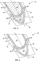
FIG. 3 is a cross sectional view of a portion of a CMC airfoil of a CMC hollow blade with internal CMC plies laid up off the mean camber line and overlapping in an embodiment of the present disclosure. -
FIG. 4 is a cross sectional view of the portion of the CMC airfoil ofFIG. 3 with the mandrel removed. - Wherever possible, the same reference numbers will be used throughout the drawings to represent the same parts.
- Provided is a ceramic matrix composite (CMC) hollow blade and a method of forming such a CMC hollow blade.
- Embodiments of the present disclosure, for example, in comparison to concepts failing to include one or more of the features disclosed herein, achieve a better tying of CMC plies, provide a stronger encapsulated insert, provide a more robust CMC airfoil system, reduce the likelihood of interlaminar crack growth in the trailing edge, target ply terminations away from the mean camber line, provide a stronger encapsulated insert, enable a more ideal ply construction, reduce fallout of parts, decrease cost, or combinations thereof.
- A cavity, as used herein, refers to any intentionally-formed void space located in the CMC airfoil of a CMC hollow blade and having a predetermined contour defined by a mandrel and/or one or more cavity CMC plies.
- An insert, as used herein, refers to any permanent structure having a non-ply contour that is placed with respect to CMC ply layers to aid in the transition of the CMC ply layers from the contour of the cavity to the contour of the outer surface of the CMC airfoil.
- A cavity CMC ply, as used herein, refers to any CMC ply that is located closer to the cavity than the outer surface of a CMC airfoil or that more closely follows the contour of the cavity of the CMC airfoil than the contour of the outer surface of the CMC airfoil.
- An airfoil CMC ply, as used herein, refers to any CMC ply that is located closer to the outer surface than the cavity of a CMC airfoil or that more closely follows the contour of the outer surface of the CMC airfoil than the contour of the cavity of the CMC airfoil.
- A mean camber line, as used herein, refers to the centerline of an airfoil between the pressure side and the suction side of the airfoil.
- Referring to
FIG. 1 , theCMC airfoil 10 of a CMC hollow blade includes a leading edge (LE) 12, a trailing edge (TE) 14, a pressure side (PS) 16, a suction side (SS) 18, and acavity 20. At least onecavity CMC ply 22 defines thecavity 20 and at least oneairfoil CMC ply 24 defines the contour of theCMC airfoil 10, including theLE 12, theTE 14, thePS 16, and theSS 18. Internal CMC plies 26 fill the space between thecavity 20 and theTE 14. At least one end of the airfoil CMC plies 24 and theinternal CMC plies 26 terminates at themean camber line 30 of theCMC airfoil 10. For clarity and simplicity, thecavity CMC plies 22,airfoil CMC plies 24, andinternal CMC plies 26 are shown schematically inFIG. 1 and FIG. 2 as lines and additionalcavity CMC plies 22,airfoil CMC plies 24, andinternal CMC plies 26 may be present in aCMC airfoil 10. - As is more clearly visible in
FIG. 2 , theinternal CMC plies 26 have varying lengths to run substantially parallel to each other while filling the space between thecavity CMC plies 22 and theairfoil CMC plies 24. As noted above, CMC hollow blades may suffer from peel stresses in theTE 14, due to pressurizing of thecavity 20 during service causing high inter-laminar tensile (ILT) ballooning stresses. This peel stress tends to be strongest along themean camber line 30 of theCMC airfoil 10. - Referring to
FIG. 3 and FIG. 4 , a firstcavity CMC ply 22 is laid up to extend along and around amandrel 40 to define thecavity 20 of theCMC airfoil 10. Themandrel 40 is ultimately removed to form thecavity 20 in theCMC airfoil 10 having the contour of themandrel 40. The firstcavity CMC ply 22 starts with afirst ply end 28 contacting themandrel 40 on theSS 18 of theCMC airfoil 10. The firstcavity CMC ply 22 then extends along themandrel 40 across themean camber line 30 on the TE end of themandrel 40 toward thePS 16 of theCMC airfoil 10, wraps themandrel 40 and overlaps itself, extends across themean camber line 30 again, and terminates at asecond ply end 28 on thePS 16 of theCMC airfoil 10, as shown inFIG. 3 and FIG. 4 . For clarity and simplicity, onlycavity CMC plies 22 are shown inFIG. 3 and FIG. 4 and thecavity CMC plies 22 are only shown schematically as lines. Airfoil CMC plies 24 and internal CMC plies 26 (seeFIG. 1 and FIG. 2 ) and additionalcavity CMC plies 22 maybe present in aCMC airfoil 10. - Alternatively, the first
cavity CMC ply 22 may start with thefirst ply end 28 contacting themandrel 40 on thePS 16 of theCMC airfoil 10. The firstcavity CMC ply 22 then extends along themandrel 40 across themean camber line 30 on the TE end of themandrel 40 toward theSS 18 of theCMC airfoil 10, wraps themandrel 40 and overlaps itself, extends across themean camber line 30 again, and terminates at asecond ply end 28 on theSS 18 of theCMC airfoil 10. - Referring to
FIG. 3 and FIG. 4 , a secondcavity CMC ply 22 is laid up starting with afirst ply end 28 contacting the firstcavity CMC ply 22 on theSS 18 of theCMC airfoil 10. The secondcavity CMC ply 22 then extends along the firstcavity CMC ply 22 across themean camber line 30 on the TE end of themandrel 40 toward thePS 16 of theCMC airfoil 10. Aninsert 50 is placed on the secondcavity CMC ply 22 on the TE side of themandrel 40. The second cavity CMC ply 22 then wraps the first cavity CMC ply 22, extends along theinsert 50 across themean camber line 30 again, and terminates at asecond ply end 28 on thePS 16 of theCMC airfoil 10, preferably wrapping theinsert 50, as shown inFIG. 3 and FIG. 4 . - Alternatively, the second cavity CMC ply 22 may start with a
first ply end 28 contacting the first cavity CMC ply 22 on thePS 16 of theCMC airfoil 10. The second cavity CMC ply 22 then extends along the first cavity CMC ply 22 across themean camber line 30 on the TE end of themandrel 40 toward theSS 18 of theCMC airfoil 10. Aninsert 50 is then placed on the second cavity CMC ply 22 on the TE side of themandrel 40. The second cavity CMC ply 22 then wraps the first cavity CMC ply 22, extends along theinsert 50 across themean camber line 30 again, and terminates at asecond ply end 28 on theSS 18 of theCMC airfoil 10, preferably wrapping theinsert 50. - The cavity CMC ply 22 that wraps the
insert 50 crosses themean camber line 30 at least twice: once on the cavity-facing edge of theinsert 50 and once on the TE-facing edge of theinsert 50. In some embodiments, the cavity CMC ply 22 or an airfoil CMC ply 24 wrapping theinsert 50 may extend more than two times across themean camber line 30. - Although
FIG. 3 and FIG. 4 show the same cavity CMC ply 22 contacting both the cavity-facing edge of theinsert 50 and the TE-facing edge of theinsert 50, different CMC plies may contact the cavity-facing edge and the TE-facing edge of theinsert 50. For example, a cavity CMC ply 22 may instead contact the cavity-facing edge of theinsert 50, while a different neighboring CMC ply, such as a cavity CMC ply 22 or an airfoil CMC ply 24, contacts the TE-facing edge of theinsert 50. - Still referring to
FIG. 3 and FIG. 4 , an internal CMC ply 26 is laid up starting with afirst ply end 28 contacting the second cavity CMC ply 22 on theSS 18 of theCMC airfoil 10. The internal CMC ply 26 then extends along the second cavity CMC ply 22 across themean camber line 30 on the TE end of themandrel 40 and insert 50 and further extends toward thePS 16 of theCMC airfoil 10. The internal CMC ply 26 then wraps the second cavity CMC ply 22, extends across themean camber line 30 again, and terminates at asecond ply end 28 on thePS 16 of theCMC airfoil 10, as shown inFIG. 3 and FIG. 4 . - Alternatively, the internal CMC ply 26 may start with a
first ply end 28 contacting the second cavity CMC ply 22 on thePS 16 of theCMC airfoil 10. The internal CMC ply 26 then extends along the second cavity CMC ply 22 across themean camber line 30 on the TE end of themandrel 40 and insert 50 toward theSS 18 of theCMC airfoil 10. The internal CMC ply 26 then wraps the second cavity CMC ply 22, extends across themean camber line 30 again, and terminates at asecond ply end 28 on theSS 18 of theCMC airfoil 10. - Similar to the
insert 50 between thecavity 20 and theTE 14 shown inFIG. 3 and FIG. 4 , aninsert 50 may alternatively or additionally be located between thecavity 20 and theLE 12 of theCMC airfoil 10. In one embodiment, additional inserts are not present between thecavity 20 and theLE 12 of theCMC airfoil 10. The arrangement, according to the present disclosure, may create larger cavity fillets that can be located closer to theTE 14 than known designs that may have a smaller arrangement. - The ply ends 28 of the cavity CMC plies 22 overlapping and being located off of the
mean camber line 30 reduces the likelihood of interlaminar crack growth in theTE 14 of theCMC airfoil 10. The ply ends 28 may be located to extend to any predetermined location past themean camber line 30 that reduces the likelihood of such interlaminar crack growth. - The
insert 50 may be made of any material compatible with the cavity CMC plies 22, airfoil CMC plies 24, and/or internal CMC plies 26 that flank or contact theinsert 50. In some embodiments, theinsert 50 is a radial roll. In some embodiments, theinsert 50 includes a matrix and a fiber material. In some embodiments, theinsert 50 includes a fiber material. In some embodiments, theinsert 50 is fully infiltrated at the time of insertion. In some embodiments, theinsert 50 includes a ply of ceramic-containing material continuously rolled onto itself to form a cylinder or other shape of ceramic-containing material ("jelly roll"). In some embodiments, theinsert 50 does not include any plies. In some embodiments, theinsert 50 does not include any infiltratable medium or solid. In some embodiments, the volume corresponding to the location of theinsert 50 is void or substantially void of material after CMC densification. - In some embodiments, the
insert 50 fills a space that would otherwise be too small for aninsert 50 or where theinsert 50 would otherwise cause too sharp of a transition for CMC plies without the overlapping of ply ends 28, as described herein. - In some embodiments, none of the ply ends 28 of the cavity CMC plies 22 and internal CMC plies 26 are located on or near the
mean camber line 30 of theCMC airfoil 10. In some embodiments, only the ply ends 28 of the outermost airfoil CMC ply 24 are located on or near themean camber line 30 of theCMC airfoil 10. In some embodiments, all of the ply ends 28 of the cavity CMC plies 22 and internal CMC plies 26 are located at least a predetermined distance away from themean camber line 30 of theCMC airfoil 10. - In some embodiments, larger power CMC parts permit TE core wraps. As shown in
FIG. 3 and FIG. 4 , the ply terminations are preferably targeted to be away from themean camber line 30. Larger power parts enable a more ideal ply construction. - The chance of interlaminar crack growth in the
TE 14 may be reduced by filling the void between thecavity 20 and theTE 14 with ahigher strength insert 50 that extends in the radial direction. Theinsert 50 is contained by overlapping fiber CMC plies. In some embodiments, theLE 12 andTE 14ply end 28 terminations are of most importance. In some embodiments, high ILT strength structures are overlapped and contained within these areas. - By wrapping the
inserts 50, which may be placed within theLE 12 and/or theTE 14 of ahollow CMC airfoil 10 with CMC plies that return from thePS 16 to theSS 18, or vice versa, a better tying of plies may be achieved. Containment CMC plies wrap from thePS 16 to theSS 18, or vice versa, around theinsert 50, where the ILT is at its maximum. - In some embodiments, the methods described herein are compatible with current fabrication techniques and aid in the formation of a CMC core.
- While the invention has been described with reference to one or more embodiments, it will be understood by those skilled in the art that various changes may be made and equivalents may be substituted for elements thereof without departing from the scope of the invention. In addition, many modifications may be made to adapt a particular situation or material to the teachings of the invention without departing from the essential scope thereof. Therefore, it is intended that the invention not be limited to the particular embodiment disclosed as the best mode contemplated for carrying out this invention, but that the invention will include all embodiments falling within the scope of the appended claims. In addition, all numerical values identified in the detailed description shall be interpreted as though the precise and approximate values are both expressly identified
- Various aspects and embodiments of the present invention are defined by the following numbered clauses:
- 1. A ceramic matrix composite (CMC) hollow blade comprising a CMC airfoil comprising:
- at least one airfoil CMC ply defining a contour of the CMC airfoil including a first edge, a second edge opposite the first edge, a first side extending from the first edge to the second edge, and a second side opposite the first side, the second side extending from the first edge to the second edge;
- at least one cavity CMC ply defining a cavity within the CMC airfoil of the CMC hollow blade; and
- a first insert located between the first edge and the cavity, the first insert being wrapped by one of the at least one airfoil CMC ply and the at least one cavity CMC ply such that the one of the at least one airfoil CMC ply and the at least one cavity CMC ply extends along the first insert from the first side of the CMC airfoil across a mean camber line of the CMC airfoil and to the second side of the CMC airfoil, the one of the at least one airfoil CMC ply and the at least one cavity CMC ply terminating at a ply end on the second side of the CMC airfoil.
- 2. The CMC hollow blade of clause 1, wherein the first insert comprises a radial roll matrix and a radial roll fiber material.
- 3. The CMC hollow blade of any preceding clause, wherein the first side is a pressure side and the second side is a suction side.
- 4. The CMC hollow blade of any preceding clause, wherein the first side is a suction side and the second side is a pressure side.
- 5. The CMC hollow blade of any preceding clause, wherein the first edge is a leading edge and the second edge is a trailing edge.
- 6. The CMC hollow blade of any preceding clause, wherein the first edge is a trailing edge and the second edge is a leading edge.
- 7. The CMC hollow blade of any preceding clause further comprising a second insert between the second edge and the cavity.
- 8. The CMC hollow blade of any preceding clause, wherein the second insert is wrapped by another of the at least one airfoil CMC ply and the at least one cavity CMC ply extending along the second insert from the first side of the CMC airfoil across a mean camber line of the CMC airfoil and to the second side of the CMC airfoil.
- 9. The CMC hollow blade of any preceding clause, wherein the ply end of the one of the at least one airfoil CMC ply and the at least one cavity CMC ply is located about 20° or more off a radial plane.
- 10. The CMC hollow blade of any preceding clause, wherein the one of the at least one airfoil CMC ply and the at least one cavity CMC ply crosses the mean camber line between the first edge and the cavity at least twice.
- 11. A method of forming a ceramic matrix composite (CMC) hollow blade, the method comprising:
- laying up at least one cavity CMC ply defining a cavity within a CMC airfoil of the CMC hollow blade;
- placing a first insert on the at least one cavity CMC ply; and
- laying up at least one airfoil CMC ply around the at least one cavity CMC ply and the first insert, the at least one airfoil CMC ply defining a contour of the CMC airfoil including a first edge, a second edge opposite the first edge, a first side extending from the first edge to the second edge, and a second side opposite the first side, the second side extending from the first edge to the second edge;
- wherein the first insert is located between the cavity and the first edge; and
- wherein the first insert is wrapped by one of the at least one airfoil CMC ply and the at least one cavity CMC ply such that the one of the at least one airfoil CMC ply and the at least one cavity CMC ply extends along the first insert from the first side of the CMC airfoil across a mean camber line of the CMC airfoil and to the second side of the CMC airfoil, the one of the at least one airfoil CMC ply and the at least one cavity CMC ply terminating at a ply end on the second side of the CMC airfoil.
- 12. The method of any preceding clause, wherein the first insert comprises a radial roll matrix and a radial roll fiber material.
- 13. The method of any preceding clause, wherein the first side is a pressure side and the second side is a suction side.
- 14. The method of any preceding clause, wherein the first side is a suction side and the second side is a pressure side.
- 15. The method of any preceding clause, wherein the first edge is a leading edge and the second edge is a trailing edge.
- 16. The method of any preceding clause, wherein the first edge is a trailing edge and the second edge is a leading edge.
- 17. The method of any preceding clause further comprising placing a second insert between the second edge and the cavity.
- 18. The method of any preceding clause further comprising wrapping the second insert by another of the at least one airfoil CMC ply and the at least one cavity CMC ply extending along the second insert from the first side of the CMC airfoil across a mean camber line of the CMC airfoil and to the second side of the CMC airfoil.
- 19. The method of any preceding clause, wherein the ply end of the one of the at least one airfoil CMC ply and the at least one cavity CMC ply is located about 20° or more off a radial plane.
- 20. The method of any preceding clause, wherein the one of the at least one airfoil CMC ply and the at least one cavity CMC ply crosses the mean camber line between the first edge and the cavity at least twice.
Claims (10)
- A ceramic matrix composite (CMC) hollow blade comprising a CMC airfoil (10) comprising:at least one airfoil CMC ply (22) defining a contour of the CMC airfoil (10) including a first edge, a second edge opposite the first edge, a first side extending from the first edge to the second edge, and a second side opposite the first side, the second side extending from the first edge to the second edge;at least one cavity CMC ply (22) defining a cavity (20) within the CMC airfoil (10) of the CMC hollow blade; anda first insert (50) located between the first edge and the cavity, the first insert (50) being wrapped by one of the at least one airfoil CMC ply (22) and the at least one cavity CMC ply (22) such that the one of the at least one airfoil CMC ply (22) and the at least one cavity CMC ply (22) extends along the first insert (50) from the first side of the CMC airfoil (10) across a mean camber line (30) of the CMC airfoil (10) and to the second side of the CMC airfoil (10), the one of the at least one airfoil CMC ply (22) and the at least one cavity CMC ply (22) terminating at a ply end (28) on the second side of the CMC airfoil (10).
- The CMC hollow blade of claim 1, wherein the first insert (50) comprises a radial roll matrix and a radial roll fiber material.
- The CMC hollow blade of claim 1 or 2 further comprising a second insert (50) between the second edge and the cavity.
- The CMC hollow blade of claim 3, wherein the second insert (50) is wrapped by another of the at least one airfoil CMC ply (22) and the at least one cavity CMC ply (22) extending along the second insert (50) from the first side of the CMC airfoil (10) across a mean camber line (30) of the CMC airfoil (10) and to the second side of the CMC airfoil (10).
- The CMC hollow blade of any preceding claim, wherein the ply end (28) of the one of the at least one airfoil CMC ply (22) and the at least one cavity CMC ply (22) is located about 20° or more off a radial plane.
- The CMC hollow blade of any preceding claim, wherein the one of the at least one airfoil CMC ply (22) and the at least one cavity CMC ply (22) crosses the mean camber line (30) between the first edge and the cavity (20) at least twice.
- A method of forming a ceramic matrix composite (CMC) hollow blade, the method comprising:laying up at least one cavity CMC ply (22) defining a cavity (20) within a CMC airfoil (10) of the CMC hollow blade;placing a first insert (50) on the at least one cavity CMC ply (22); andlaying up at least one airfoil CMC ply (22) around the at least one cavity CMC ply (22) and the first insert (50), the at least one airfoil CMC ply (22) defining a contour of the CMC airfoil (10) including a first edge, a second edge opposite the first edge, a first side extending from the first edge to the second edge, and a second side opposite the first side, the second side extending from the first edge to the second edge;wherein the first insert (50) is located between the cavity (20) and the first edge; andwherein the first insert (50) is wrapped by one of the at least one airfoil CMC ply (22) and the at least one cavity CMC ply (22) such that the one of the at least one airfoil CMC ply (22) and the at least one cavity CMC ply (22) extends along the first insert (50) from the first side of the CMC airfoil (10) across a mean camber line (30) of the CMC airfoil (10) and to the second side of the CMC airfoil (10), the one of the at least one airfoil CMC ply (22) and the at least one cavity CMC ply (22) terminating at a ply end (28) on the second side of the CMC airfoil (10).
- The method of claim 7 further comprising placing a second insert (50) between the second edge and the cavity.
- The method of claim 8 further comprising wrapping the second insert (50) by another of the at least one airfoil CMC ply (22) and the at least one cavity CMC ply (22) extending along the second insert (50) from the first side of the CMC airfoil (10) across a mean camber line (30) of the CMC airfoil (10) and to the second side of the CMC airfoil (10).
- The method of claim 7, 8 or 9, wherein the ply end (28) of the one of the at least one airfoil CMC ply (22) and the at least one cavity CMC ply (22) is located about 20° or more off a radial plane.
Applications Claiming Priority (1)
| Application Number | Priority Date | Filing Date | Title |
|---|---|---|---|
| US15/624,893 US10443410B2 (en) | 2017-06-16 | 2017-06-16 | Ceramic matrix composite (CMC) hollow blade and method of forming CMC hollow blade |
Publications (2)
| Publication Number | Publication Date |
|---|---|
| EP3415717A1 true EP3415717A1 (en) | 2018-12-19 |
| EP3415717B1 EP3415717B1 (en) | 2021-08-18 |
Family
ID=61965772
Family Applications (1)
| Application Number | Title | Priority Date | Filing Date |
|---|---|---|---|
| EP18166544.9A Active EP3415717B1 (en) | 2017-06-16 | 2018-04-10 | Ceramic matrix composite (cmc) hollow blade and method of forming such blade |
Country Status (3)
| Country | Link |
|---|---|
| US (1) | US10443410B2 (en) |
| EP (1) | EP3415717B1 (en) |
| JP (1) | JP7118719B2 (en) |
Cited By (4)
| Publication number | Priority date | Publication date | Assignee | Title |
|---|---|---|---|---|
| EP3865667A1 (en) * | 2020-02-14 | 2021-08-18 | Rolls-Royce plc | Variable stator vane and method of fabricating variable stator vane |
| EP4030037A1 (en) * | 2021-01-15 | 2022-07-20 | Raytheon Technologies Corporation | Airfoil with wishbone fiber composite structure |
| EP4137668A1 (en) * | 2021-08-19 | 2023-02-22 | Raytheon Technologies Corporation | Cmc gas turbine engine component with separated fiber plies |
| US11920495B1 (en) | 2023-01-20 | 2024-03-05 | Rtx Corporation | Airfoil with thick wishbone fiber structure |
Families Citing this family (5)
| Publication number | Priority date | Publication date | Assignee | Title |
|---|---|---|---|---|
| GB2573137B (en) * | 2018-04-25 | 2020-09-23 | Rolls Royce Plc | CMC aerofoil |
| EP4283095B1 (en) | 2022-05-27 | 2025-09-10 | RTX Corporation | Cmc laminate airfoil with ply drops |
| US12110807B1 (en) * | 2023-03-14 | 2024-10-08 | Rtx Corporation | Altering structural response of two-piece hollow-vane assembly by changing the cover composition |
| US12241385B2 (en) | 2023-07-17 | 2025-03-04 | Rtx Corporation | Wishbone fiber layup structure for airfoil |
| US12601267B2 (en) * | 2024-02-15 | 2026-04-14 | Rtx Corporation | Forming gas turbine engine airfoils from CMCs with a kickback to facilitate mandrel removal |
Citations (2)
| Publication number | Priority date | Publication date | Assignee | Title |
|---|---|---|---|---|
| US20050238491A1 (en) * | 2004-04-22 | 2005-10-27 | Siemens Westinghouse Power Corporation | Ceramic matrix composite airfoil trailing edge arrangement |
| US20090165924A1 (en) * | 2006-11-28 | 2009-07-02 | General Electric Company | Method of manufacturing cmc articles having small complex features |
Family Cites Families (19)
| Publication number | Priority date | Publication date | Assignee | Title |
|---|---|---|---|---|
| US20040099391A1 (en) * | 2002-11-26 | 2004-05-27 | Bob Ching | Process for producing super high bulk, light weight coated papers |
| US7435058B2 (en) * | 2005-01-18 | 2008-10-14 | Siemens Power Generation, Inc. | Ceramic matrix composite vane with chordwise stiffener |
| US7600978B2 (en) * | 2006-07-27 | 2009-10-13 | Siemens Energy, Inc. | Hollow CMC airfoil with internal stitch |
| US20090014926A1 (en) * | 2007-07-09 | 2009-01-15 | Siemens Power Generation, Inc. | Method of constructing a hollow fiber reinforced structure |
| US8357323B2 (en) * | 2008-07-16 | 2013-01-22 | Siemens Energy, Inc. | Ceramic matrix composite wall with post laminate stitching |
| US20110206522A1 (en) * | 2010-02-24 | 2011-08-25 | Ioannis Alvanos | Rotating airfoil fabrication utilizing cmc |
| US8794925B2 (en) | 2010-08-24 | 2014-08-05 | United Technologies Corporation | Root region of a blade for a gas turbine engine |
| US8967961B2 (en) * | 2011-12-01 | 2015-03-03 | United Technologies Corporation | Ceramic matrix composite airfoil structure with trailing edge support for a gas turbine engine |
| US9598967B2 (en) | 2012-12-18 | 2017-03-21 | United Technologies Corporation | Airfoil member and composite platform having contoured endwall |
| US10487675B2 (en) * | 2013-02-18 | 2019-11-26 | United Technologies Corporation | Stress mitigation feature for composite airfoil leading edge |
| WO2014133721A1 (en) * | 2013-02-27 | 2014-09-04 | United Technologies Corporation | Gas turbine engine thin wall composite vane airfoil |
| WO2014186011A2 (en) * | 2013-03-01 | 2014-11-20 | United Technologies Corporation | Gas turbine engine composite airfoil trailing edge |
| CA2899891A1 (en) * | 2013-03-14 | 2014-10-02 | Adam L. CHAMBERLAIN | Bi-cast turbine vane |
| US10132170B2 (en) * | 2013-03-15 | 2018-11-20 | General Electric Company | Systems and method for a composite blade with fillet transition |
| WO2014193565A1 (en) * | 2013-05-29 | 2014-12-04 | General Electric Company | Method of forming a ceramic matrix composite component with cooling features |
| US10273813B2 (en) * | 2015-10-29 | 2019-04-30 | General Electric Company | Ceramic matrix composite component and process of producing a ceramic matrix composite component |
| US20170268344A1 (en) * | 2016-03-18 | 2017-09-21 | Siemens Energy, Inc. | Laser joining of cmc stacks |
| US10207471B2 (en) * | 2016-05-04 | 2019-02-19 | General Electric Company | Perforated ceramic matrix composite ply, ceramic matrix composite article, and method for forming ceramic matrix composite article |
| US10731481B2 (en) * | 2016-11-01 | 2020-08-04 | Rolls-Royce Corporation | Turbine blade with ceramic matrix composite material construction |
-
2017
- 2017-06-16 US US15/624,893 patent/US10443410B2/en active Active
-
2018
- 2018-04-10 EP EP18166544.9A patent/EP3415717B1/en active Active
- 2018-04-20 JP JP2018081314A patent/JP7118719B2/en active Active
Patent Citations (2)
| Publication number | Priority date | Publication date | Assignee | Title |
|---|---|---|---|---|
| US20050238491A1 (en) * | 2004-04-22 | 2005-10-27 | Siemens Westinghouse Power Corporation | Ceramic matrix composite airfoil trailing edge arrangement |
| US20090165924A1 (en) * | 2006-11-28 | 2009-07-02 | General Electric Company | Method of manufacturing cmc articles having small complex features |
Cited By (7)
| Publication number | Priority date | Publication date | Assignee | Title |
|---|---|---|---|---|
| EP3865667A1 (en) * | 2020-02-14 | 2021-08-18 | Rolls-Royce plc | Variable stator vane and method of fabricating variable stator vane |
| US11448086B2 (en) | 2020-02-14 | 2022-09-20 | Rolls-Royce Plc | Variable stator vane and method of fabricating variable stator vane |
| EP4030037A1 (en) * | 2021-01-15 | 2022-07-20 | Raytheon Technologies Corporation | Airfoil with wishbone fiber composite structure |
| US11725522B2 (en) | 2021-01-15 | 2023-08-15 | Raytheon Technologies Corporation | Airfoil with wishbone fiber structure |
| EP4137668A1 (en) * | 2021-08-19 | 2023-02-22 | Raytheon Technologies Corporation | Cmc gas turbine engine component with separated fiber plies |
| US12104496B2 (en) | 2021-08-19 | 2024-10-01 | Rtx Corporation | CMC gas turbine engine component with separated fiber plies |
| US11920495B1 (en) | 2023-01-20 | 2024-03-05 | Rtx Corporation | Airfoil with thick wishbone fiber structure |
Also Published As
| Publication number | Publication date |
|---|---|
| JP2019011751A (en) | 2019-01-24 |
| JP7118719B2 (en) | 2022-08-16 |
| US20180363475A1 (en) | 2018-12-20 |
| US10443410B2 (en) | 2019-10-15 |
| EP3415717B1 (en) | 2021-08-18 |
Similar Documents
| Publication | Publication Date | Title |
|---|---|---|
| US10443410B2 (en) | Ceramic matrix composite (CMC) hollow blade and method of forming CMC hollow blade | |
| EP2893150B1 (en) | Airfoil components containing ceramic-based materials and processes therefor | |
| JP5960988B2 (en) | Fiber reinforced Al-Li compressor airfoil and manufacturing method | |
| CN104203523B (en) | For the production of the method for ceramic composite member | |
| US8980435B2 (en) | CMC component, power generation system and method of forming a CMC component | |
| US7066717B2 (en) | Ceramic matrix composite airfoil trailing edge arrangement | |
| US8607454B2 (en) | Method for producing a turbomachine blade made from a composite material | |
| CN106870016A (en) | The process of ceramic matrix composite component and production ceramic matrix composite component | |
| EP3440316A1 (en) | Ceramic component for combustion turbine engines | |
| CN108952818B (en) | CMC turbine blade assembly, dovetail sleeve and method of installing CMC turbine blade | |
| US11384646B2 (en) | Method for forming hollow ceramic matrix composite article using a mandrel | |
| EP3415721B1 (en) | Ceramic matrix composite (cmc) turbine blades and methods of forming cmc turbine blades | |
| EP4571048A1 (en) | Method to tie composite vane platform and airfoil design details | |
| FR3166826A1 (en) | FIBROUS STRUCTURE FOR THE PRODUCTION OF A PART IN COMPOSITE MATERIAL |
Legal Events
| Date | Code | Title | Description |
|---|---|---|---|
| PUAI | Public reference made under article 153(3) epc to a published international application that has entered the european phase |
Free format text: ORIGINAL CODE: 0009012 |
|
| STAA | Information on the status of an ep patent application or granted ep patent |
Free format text: STATUS: THE APPLICATION HAS BEEN PUBLISHED |
|
| AK | Designated contracting states |
Kind code of ref document: A1 Designated state(s): AL AT BE BG CH CY CZ DE DK EE ES FI FR GB GR HR HU IE IS IT LI LT LU LV MC MK MT NL NO PL PT RO RS SE SI SK SM TR |
|
| AX | Request for extension of the european patent |
Extension state: BA ME |
|
| STAA | Information on the status of an ep patent application or granted ep patent |
Free format text: STATUS: REQUEST FOR EXAMINATION WAS MADE |
|
| 17P | Request for examination filed |
Effective date: 20190614 |
|
| RBV | Designated contracting states (corrected) |
Designated state(s): AL AT BE BG CH CY CZ DE DK EE ES FI FR GB GR HR HU IE IS IT LI LT LU LV MC MK MT NL NO PL PT RO RS SE SI SK SM TR |
|
| STAA | Information on the status of an ep patent application or granted ep patent |
Free format text: STATUS: EXAMINATION IS IN PROGRESS |
|
| 17Q | First examination report despatched |
Effective date: 20200929 |
|
| GRAP | Despatch of communication of intention to grant a patent |
Free format text: ORIGINAL CODE: EPIDOSNIGR1 |
|
| STAA | Information on the status of an ep patent application or granted ep patent |
Free format text: STATUS: GRANT OF PATENT IS INTENDED |
|
| INTG | Intention to grant announced |
Effective date: 20210316 |
|
| GRAS | Grant fee paid |
Free format text: ORIGINAL CODE: EPIDOSNIGR3 |
|
| GRAA | (expected) grant |
Free format text: ORIGINAL CODE: 0009210 |
|
| STAA | Information on the status of an ep patent application or granted ep patent |
Free format text: STATUS: THE PATENT HAS BEEN GRANTED |
|
| AK | Designated contracting states |
Kind code of ref document: B1 Designated state(s): AL AT BE BG CH CY CZ DE DK EE ES FI FR GB GR HR HU IE IS IT LI LT LU LV MC MK MT NL NO PL PT RO RS SE SI SK SM TR |
|
| REG | Reference to a national code |
Ref country code: GB Ref legal event code: FG4D |
|
| REG | Reference to a national code |
Ref country code: CH Ref legal event code: EP |
|
| REG | Reference to a national code |
Ref country code: DE Ref legal event code: R096 Ref document number: 602018021892 Country of ref document: DE |
|
| REG | Reference to a national code |
Ref country code: IE Ref legal event code: FG4D Ref country code: AT Ref legal event code: REF Ref document number: 1421820 Country of ref document: AT Kind code of ref document: T Effective date: 20210915 |
|
| REG | Reference to a national code |
Ref country code: LT Ref legal event code: MG9D |
|
| REG | Reference to a national code |
Ref country code: NL Ref legal event code: MP Effective date: 20210818 |
|
| REG | Reference to a national code |
Ref country code: AT Ref legal event code: MK05 Ref document number: 1421820 Country of ref document: AT Kind code of ref document: T Effective date: 20210818 |
|
| PG25 | Lapsed in a contracting state [announced via postgrant information from national office to epo] |
Ref country code: PT Free format text: LAPSE BECAUSE OF FAILURE TO SUBMIT A TRANSLATION OF THE DESCRIPTION OR TO PAY THE FEE WITHIN THE PRESCRIBED TIME-LIMIT Effective date: 20211220 Ref country code: NO Free format text: LAPSE BECAUSE OF FAILURE TO SUBMIT A TRANSLATION OF THE DESCRIPTION OR TO PAY THE FEE WITHIN THE PRESCRIBED TIME-LIMIT Effective date: 20211118 Ref country code: BG Free format text: LAPSE BECAUSE OF FAILURE TO SUBMIT A TRANSLATION OF THE DESCRIPTION OR TO PAY THE FEE WITHIN THE PRESCRIBED TIME-LIMIT Effective date: 20211118 Ref country code: AT Free format text: LAPSE BECAUSE OF FAILURE TO SUBMIT A TRANSLATION OF THE DESCRIPTION OR TO PAY THE FEE WITHIN THE PRESCRIBED TIME-LIMIT Effective date: 20210818 Ref country code: LT Free format text: LAPSE BECAUSE OF FAILURE TO SUBMIT A TRANSLATION OF THE DESCRIPTION OR TO PAY THE FEE WITHIN THE PRESCRIBED TIME-LIMIT Effective date: 20210818 Ref country code: HR Free format text: LAPSE BECAUSE OF FAILURE TO SUBMIT A TRANSLATION OF THE DESCRIPTION OR TO PAY THE FEE WITHIN THE PRESCRIBED TIME-LIMIT Effective date: 20210818 Ref country code: FI Free format text: LAPSE BECAUSE OF FAILURE TO SUBMIT A TRANSLATION OF THE DESCRIPTION OR TO PAY THE FEE WITHIN THE PRESCRIBED TIME-LIMIT Effective date: 20210818 Ref country code: ES Free format text: LAPSE BECAUSE OF FAILURE TO SUBMIT A TRANSLATION OF THE DESCRIPTION OR TO PAY THE FEE WITHIN THE PRESCRIBED TIME-LIMIT Effective date: 20210818 Ref country code: SE Free format text: LAPSE BECAUSE OF FAILURE TO SUBMIT A TRANSLATION OF THE DESCRIPTION OR TO PAY THE FEE WITHIN THE PRESCRIBED TIME-LIMIT Effective date: 20210818 Ref country code: RS Free format text: LAPSE BECAUSE OF FAILURE TO SUBMIT A TRANSLATION OF THE DESCRIPTION OR TO PAY THE FEE WITHIN THE PRESCRIBED TIME-LIMIT Effective date: 20210818 |
|
| PG25 | Lapsed in a contracting state [announced via postgrant information from national office to epo] |
Ref country code: PL Free format text: LAPSE BECAUSE OF FAILURE TO SUBMIT A TRANSLATION OF THE DESCRIPTION OR TO PAY THE FEE WITHIN THE PRESCRIBED TIME-LIMIT Effective date: 20210818 Ref country code: LV Free format text: LAPSE BECAUSE OF FAILURE TO SUBMIT A TRANSLATION OF THE DESCRIPTION OR TO PAY THE FEE WITHIN THE PRESCRIBED TIME-LIMIT Effective date: 20210818 Ref country code: GR Free format text: LAPSE BECAUSE OF FAILURE TO SUBMIT A TRANSLATION OF THE DESCRIPTION OR TO PAY THE FEE WITHIN THE PRESCRIBED TIME-LIMIT Effective date: 20211119 |
|
| PG25 | Lapsed in a contracting state [announced via postgrant information from national office to epo] |
Ref country code: NL Free format text: LAPSE BECAUSE OF FAILURE TO SUBMIT A TRANSLATION OF THE DESCRIPTION OR TO PAY THE FEE WITHIN THE PRESCRIBED TIME-LIMIT Effective date: 20210818 |
|
| PG25 | Lapsed in a contracting state [announced via postgrant information from national office to epo] |
Ref country code: DK Free format text: LAPSE BECAUSE OF FAILURE TO SUBMIT A TRANSLATION OF THE DESCRIPTION OR TO PAY THE FEE WITHIN THE PRESCRIBED TIME-LIMIT Effective date: 20210818 |
|
| REG | Reference to a national code |
Ref country code: DE Ref legal event code: R097 Ref document number: 602018021892 Country of ref document: DE |
|
| PG25 | Lapsed in a contracting state [announced via postgrant information from national office to epo] |
Ref country code: SM Free format text: LAPSE BECAUSE OF FAILURE TO SUBMIT A TRANSLATION OF THE DESCRIPTION OR TO PAY THE FEE WITHIN THE PRESCRIBED TIME-LIMIT Effective date: 20210818 Ref country code: SK Free format text: LAPSE BECAUSE OF FAILURE TO SUBMIT A TRANSLATION OF THE DESCRIPTION OR TO PAY THE FEE WITHIN THE PRESCRIBED TIME-LIMIT Effective date: 20210818 Ref country code: RO Free format text: LAPSE BECAUSE OF FAILURE TO SUBMIT A TRANSLATION OF THE DESCRIPTION OR TO PAY THE FEE WITHIN THE PRESCRIBED TIME-LIMIT Effective date: 20210818 Ref country code: EE Free format text: LAPSE BECAUSE OF FAILURE TO SUBMIT A TRANSLATION OF THE DESCRIPTION OR TO PAY THE FEE WITHIN THE PRESCRIBED TIME-LIMIT Effective date: 20210818 Ref country code: CZ Free format text: LAPSE BECAUSE OF FAILURE TO SUBMIT A TRANSLATION OF THE DESCRIPTION OR TO PAY THE FEE WITHIN THE PRESCRIBED TIME-LIMIT Effective date: 20210818 Ref country code: AL Free format text: LAPSE BECAUSE OF FAILURE TO SUBMIT A TRANSLATION OF THE DESCRIPTION OR TO PAY THE FEE WITHIN THE PRESCRIBED TIME-LIMIT Effective date: 20210818 |
|
| PLBE | No opposition filed within time limit |
Free format text: ORIGINAL CODE: 0009261 |
|
| STAA | Information on the status of an ep patent application or granted ep patent |
Free format text: STATUS: NO OPPOSITION FILED WITHIN TIME LIMIT |
|
| 26N | No opposition filed |
Effective date: 20220519 |
|
| PG25 | Lapsed in a contracting state [announced via postgrant information from national office to epo] |
Ref country code: IT Free format text: LAPSE BECAUSE OF FAILURE TO SUBMIT A TRANSLATION OF THE DESCRIPTION OR TO PAY THE FEE WITHIN THE PRESCRIBED TIME-LIMIT Effective date: 20210818 |
|
| PG25 | Lapsed in a contracting state [announced via postgrant information from national office to epo] |
Ref country code: SI Free format text: LAPSE BECAUSE OF FAILURE TO SUBMIT A TRANSLATION OF THE DESCRIPTION OR TO PAY THE FEE WITHIN THE PRESCRIBED TIME-LIMIT Effective date: 20210818 |
|
| REG | Reference to a national code |
Ref country code: CH Ref legal event code: PL |
|
| REG | Reference to a national code |
Ref country code: BE Ref legal event code: MM Effective date: 20220430 |
|
| PG25 | Lapsed in a contracting state [announced via postgrant information from national office to epo] |
Ref country code: MC Free format text: LAPSE BECAUSE OF FAILURE TO SUBMIT A TRANSLATION OF THE DESCRIPTION OR TO PAY THE FEE WITHIN THE PRESCRIBED TIME-LIMIT Effective date: 20210818 Ref country code: LU Free format text: LAPSE BECAUSE OF NON-PAYMENT OF DUE FEES Effective date: 20220410 Ref country code: LI Free format text: LAPSE BECAUSE OF NON-PAYMENT OF DUE FEES Effective date: 20220430 Ref country code: FR Free format text: LAPSE BECAUSE OF NON-PAYMENT OF DUE FEES Effective date: 20220430 Ref country code: CH Free format text: LAPSE BECAUSE OF NON-PAYMENT OF DUE FEES Effective date: 20220430 |
|
| PG25 | Lapsed in a contracting state [announced via postgrant information from national office to epo] |
Ref country code: BE Free format text: LAPSE BECAUSE OF NON-PAYMENT OF DUE FEES Effective date: 20220430 |
|
| PG25 | Lapsed in a contracting state [announced via postgrant information from national office to epo] |
Ref country code: IE Free format text: LAPSE BECAUSE OF NON-PAYMENT OF DUE FEES Effective date: 20220410 |
|
| REG | Reference to a national code |
Ref country code: DE Ref legal event code: R081 Ref document number: 602018021892 Country of ref document: DE Owner name: GENERAL ELECTRIC TECHNOLOGY GMBH, CH Free format text: FORMER OWNER: GENERAL ELECTRIC COMPANY, SCHENECTADY, NY, US |
|
| REG | Reference to a national code |
Ref country code: GB Ref legal event code: 732E Free format text: REGISTERED BETWEEN 20240222 AND 20240228 |
|
| PG25 | Lapsed in a contracting state [announced via postgrant information from national office to epo] |
Ref country code: HU Free format text: LAPSE BECAUSE OF FAILURE TO SUBMIT A TRANSLATION OF THE DESCRIPTION OR TO PAY THE FEE WITHIN THE PRESCRIBED TIME-LIMIT; INVALID AB INITIO Effective date: 20180410 |
|
| PG25 | Lapsed in a contracting state [announced via postgrant information from national office to epo] |
Ref country code: MK Free format text: LAPSE BECAUSE OF FAILURE TO SUBMIT A TRANSLATION OF THE DESCRIPTION OR TO PAY THE FEE WITHIN THE PRESCRIBED TIME-LIMIT Effective date: 20210818 Ref country code: CY Free format text: LAPSE BECAUSE OF FAILURE TO SUBMIT A TRANSLATION OF THE DESCRIPTION OR TO PAY THE FEE WITHIN THE PRESCRIBED TIME-LIMIT Effective date: 20210818 |
|
| PG25 | Lapsed in a contracting state [announced via postgrant information from national office to epo] |
Ref country code: TR Free format text: LAPSE BECAUSE OF FAILURE TO SUBMIT A TRANSLATION OF THE DESCRIPTION OR TO PAY THE FEE WITHIN THE PRESCRIBED TIME-LIMIT Effective date: 20210818 |
|
| PG25 | Lapsed in a contracting state [announced via postgrant information from national office to epo] |
Ref country code: MT Free format text: LAPSE BECAUSE OF FAILURE TO SUBMIT A TRANSLATION OF THE DESCRIPTION OR TO PAY THE FEE WITHIN THE PRESCRIBED TIME-LIMIT Effective date: 20210818 |
|
| PGFP | Annual fee paid to national office [announced via postgrant information from national office to epo] |
Ref country code: DE Payment date: 20250319 Year of fee payment: 8 |
|
| PGFP | Annual fee paid to national office [announced via postgrant information from national office to epo] |
Ref country code: GB Payment date: 20260319 Year of fee payment: 9 |