EP3415460A1 - Load handling crane with high seat and portable manoeuvring unit - Google Patents
Load handling crane with high seat and portable manoeuvring unit Download PDFInfo
- Publication number
- EP3415460A1 EP3415460A1 EP17176206.5A EP17176206A EP3415460A1 EP 3415460 A1 EP3415460 A1 EP 3415460A1 EP 17176206 A EP17176206 A EP 17176206A EP 3415460 A1 EP3415460 A1 EP 3415460A1
- Authority
- EP
- European Patent Office
- Prior art keywords
- crane
- attachment
- portable
- manoeuvring
- operator
- Prior art date
- Legal status (The legal status is an assumption and is not a legal conclusion. Google has not performed a legal analysis and makes no representation as to the accuracy of the status listed.)
- Granted
Links
Images




Classifications
-
- B—PERFORMING OPERATIONS; TRANSPORTING
- B66—HOISTING; LIFTING; HAULING
- B66C—CRANES; LOAD-ENGAGING ELEMENTS OR DEVICES FOR CRANES, CAPSTANS, WINCHES, OR TACKLES
- B66C13/00—Other constructional features or details
- B66C13/18—Control systems or devices
- B66C13/40—Applications of devices for transmitting control pulses; Applications of remote control devices
-
- B—PERFORMING OPERATIONS; TRANSPORTING
- B66—HOISTING; LIFTING; HAULING
- B66C—CRANES; LOAD-ENGAGING ELEMENTS OR DEVICES FOR CRANES, CAPSTANS, WINCHES, OR TACKLES
- B66C23/00—Cranes comprising essentially a beam, boom, or triangular structure acting as a cantilever and mounted for translatory of swinging movements in vertical or horizontal planes or a combination of such movements, e.g. jib-cranes, derricks, tower cranes
- B66C23/54—Cranes comprising essentially a beam, boom, or triangular structure acting as a cantilever and mounted for translatory of swinging movements in vertical or horizontal planes or a combination of such movements, e.g. jib-cranes, derricks, tower cranes with pneumatic or hydraulic motors, e.g. for actuating jib-cranes on tractors
Definitions
- the present invention relates to a load handling crane according to the preamble of claim 1.
- a load handling crane in the form of a conventional lorry crane or forestry crane normally comprises a column, which is rotatable about a vertical axis of rotation, and a crane boom system, which is mounted to the column and which is intended to carry a load via a load handling tool suspended at a boom tip of the crane boom system, i.e. at the outer end of the outermost crane boom of the crane boom system.
- the load handling crane also comprises a manoeuvring unit with one or more manoeuvring members configured to be manoeuvrable by a crane operator in order to control the crane boom movements.
- the individual movements of the crane booms of the crane boom system are regulated by an electronic control device based on control signals from the manoeuvring unit.
- the manoeuvring unit is normally portable and configured to be carried by the crane operator, for instance by means of a waist belt or harness.
- Some load handling cranes are provided with a high seat arrangement with an elevated platform mounted to the column of the crane and with an operator's seat arranged in the open air on the platform, wherein the crane operator, when controlling the crane boom movements, may sit on the operator's seat with a good view over the working area of the crane.
- the object of the present invention is to improve the possibilities for a crane operator to use a portable manoeuvring unit in a convenient manner when being seated on an operator's seat of a high seat arrangement of the above-mentioned type.
- said object is achieved by means of a load handling crane having the features defined in claim 1.
- the load handling crane according to the invention comprises:
- the stand is pivotally mounted to the high seat platform, wherein the stand is pivotable in relation to the high seat platform between a use position, in which the stand keeps the attachment in an advanced position close to the operator's seat, and a non-use position, in which the stand keeps the attachment in a retracted position further away from the operator's seat.
- the stand is intended to be moved from the non-use position to the use position when the crane operator has climbed up onto the high seat platform and placed himself/herself on the operator's seat.
- the stand is intended to be moved from the use position to the non-use position.
- the portable manoeuvring unit may be positioned close to operator's seat in an ergonomically suitable position when the crane operator is sitting on the operator's seat and moved away from the operator's seat in order to leave room for the crane operator when he/she moves into or out of the operator's seat.
- the pillar is telescopically extensible in order to allow an adjustment of the vertical position of said attachment by an adjustment of the length of the pillar.
- the stand can easily be adapted to suit the length of the crane operator.
- said attachment is pivotally connected to the upper end of the pillar and moveable into different pivotal positions in relation to the pillar in order to allow an adjustment of the inclination of the attachment in relation to the pillar and thereby an adjustment of the inclination of the attachment in relation to the operator's seat, wherein the attachment is lockable to the pillar in a desired pivotal position by means of a locking mechanism.
- the crane operator can easily adjust the inclination of the portable manoeuvring unit as desired.
- the stand is biased towards the non-use position by a lockable gas spring, wherein the stand is pivotable from the non-use position to the use position against the action of the lockable gas spring and pivotable from the use position to the non-use position under the action of the lockable gas spring.
- the lockable gas spring makes it possible for the crane operator to position and lock the stand in a desired pivotal position in a simple and rapid manner.
- liftable and lowerable crane boom refers to a crane boom which can be pivoted in a vertical plane so as to thereby perform liftings and lowerings of a load carried by the crane.
- hydraulic cylinder for lifting and lowering the crane boom here refers to the hydraulic cylinder which is associated with the liftable and lowerable crane boom and which carries out the pivoting thereof in a vertical plane.
- Fig 1 shows a hydraulic load handling crane 1 according to an embodiment of the present invention.
- the crane 1 comprises a crane base 4, which is to be connected to the chassis of a vehicle, for instance in the form of a lorry.
- the crane 1 further comprises:
- the crane boom system 11 of the crane 1 is formed by the inner boom 7 and the outer boom 9 and the associated hydraulic cylinders 8, 10.
- the crane boom system 11 of the crane 1 may as an alternative include more than two liftable and lowerable crane booms articulately connected to each other.
- One or more of the crane booms of the crane boom system 11 may be telescopically extensible, for instance by means of one or more hydraulic cylinders, in order to enable an adjustment of the extension length thereof.
- the outer boom 9 is telescopically extensible and comprises a base section 9a and several telescopic crane boom sections 9b which are mutually slidable in relation to each other in the longitudinal direction of the outer boom 9 for adjustment of the extension length thereof.
- the telescopic crane boom sections 9b are displaceable in relation to the base section 9a and in relation to each other by means of hydraulic cylinders 12 carried by the outer boom 9.
- the load handling crane 1 is provided with a support leg arrangement 20 for supporting the crane.
- the support leg arrangement 20 comprises a base structure 21 fixedly connected to the crane base 4 and at least two support legs 22a, 22b moveably mounted to the base structure 21 on opposite sides of the crane base 4.
- the support leg arrangement 20 comprises a first support leg 22a provided on a first side of the crane base 4 and a second support leg 22b provided on an opposite second side of the crane base 4, wherein each support leg 22a, 22b is moveable in a horizontal direction in relation to the crane base 4 by means of an actuator (not shown), for instance in the form of a hydraulic cylinder or any other suitable type of linear actuator, between a retracted position close to the base structure 21 and an extended position (see Fig 1 ) at a further distance from the base structure 21.
- an actuator not shown
- each support leg 22a, 22b is fixed at the outer end of a telescopically extensible support leg beam 23a, 23b, which is slidably mounted to the base structure 21 so as to be horizontally moveable in relation to the base structure. Furthermore, each support leg 22a, 22b is telescopically extensible in a vertical direction by means of an actuator 24a, 24b, for instance in the form of a hydraulic cylinder or any other suitable type of linear actuator.
- a foot plate 25a, 25b is provided at the outer end of each support leg 22a, 22b, wherein this foot plate 25a, 25b is moveable, by a vertical extension of the support leg, from a non-use position (see Fig 1 ), in which the foot plate 25a, 25b is lifted from the ground, to an operating position, in which the foot plate 25a, 25b is in supporting contact with the ground.
- each support leg 22a, 22b could be pivotally mounted to the base structure 21 of the support leg arrangement 20 so as to be pivotable by means of an actuator, for instance in the form of a hydraulic cylinder, between a non-use position and an operating position.
- the load handling crane 1 is also provided with a high seat arrangement 30 comprising a high seat platform 31 and an operator's seat 32 mounted to the high seat platform.
- the operator's seat 32 is arranged in the open air on the high seat platform 31.
- the high seat platform 31 is fixedly connected to the column 5 at an elevated position and is rotatable in relation to the crane base 4 together with the column 5.
- the high seat platform 31 and the operator's seat 32 rotate together with the crane boom system 11 and the column 5 about the above-mentioned vertical axis of rotation when the column 5 is rotated in relation to the crane base 4 by means of the actuator 6.
- the crane operator may sit on the operator's seat 32 when controlling the movement of the support legs 22a, 22a and the movement of the crane booms 7, 9.
- the crane operator From the elevated position at the high seat platform 31, the crane operator has a good view over the operating areas of the support legs 22a, 22a and over the working area of the crane boom system 11.
- the crane operator may climb up to the high seat platform 31 through a ladder 33, which is fixedly connected to the crane base 4.
- the load handling crane 1 comprises a portable manoeuvring unit 60 with one or more maneuvering members 61a, 61 b (see Figs 2-4 ) configured to be manoeuvrable by the crane operator in order to control the movement of the support legs 22a, 22b, the rotation of the column 5 and the movement of the crane booms 7, 9.
- Control signals are transmitted via a wireless connection from the portable manoeuvring unit 60 to an electronic control device 70 (very schematically illustrated in Fig 13 ), which in its turn controls the above-mentioned hydraulic cylinders and actuators of the crane 1 in a conventional manner in dependence on the control signals from the portable manoeuvring unit 60 related to the manoeuvring of the manoeuvring members 61a, 61 b.
- the electronic control device 70 comprises a microprocessor or the similar for processing the control signals from the portable manoeuvring unit 60.
- the manoeuvring members 61 a, 61 b may for instance consist of joysticks, as shown in Figs 2-4 , but any other suitable type of manoeuvring members may also be used, such as for instance toggle levers or the similar.
- the high seat arrangement 30 comprises a stand 34, which is mounted to the high seat platform 31, and an attachment 35 configured for releasable engagement with the portable manoeuvring unit 60.
- the attachment 35 is fixed to the stand 34 and the manoeuvring unit 60 is detachably mountable to the attachment 35 in order to allow the manoeuvring unit 60 to be firmly fixed to and carried by the stand 34.
- the stand 34 is capable of positioning the attachment 35 in such a position in front of the operator's seat 32 that a crane operator sitting on the operator's seat 32 will be able to manoeuvre the manoeuvring members 61a, 61 b on the portable manoeuvring unit 60 in a convenient manner when the manoeuvring unit 60 is mounted to the attachment 35.
- the stand 34 is preferably adjustable so as to allow an adjustment of the position of the attachment 35 in relation to the operator's seat 32.
- the stand 34 is with advantage pivotally mounted to the high seat platform 31, wherein the stand 34 is pivotable in relation to the high seat platform 31 between a use position (see Figs 2 and 3 ), in which the stand 34 keeps the attachment 35 in an advanced position close to the operator's seat 32, and a non-use position (see Fig 4 ), in which the stand 34 keeps the attachment 35 in a retracted position further away from the operator's seat 32.
- the stand 34 comprises a base 36 and a pillar 37, wherein the base 36 is pivotally mounted to the high seat platform 31 through a joint 38 (see Figs 8-10 ) which forms a horizontal pivot axis for the stand.
- the pillar 37 has a lower end and an upper end, wherein the pillar 37 is fixed to the base 36 at its lower end and the attachment 35 is fixed to the upper end of the pillar.
- the base 36 has the form of an elongated bar with a first end 36a and an opposite second end 36b, wherein the base 36 is pivotally mounted to the high seat platform 31 at its first end 36a and the pillar 37 is fixed to the base 36 at the second end 36b thereof.
- the pillar 37 is preferably fixed to the base 36 with the longitudinal axis of the pillar 37 extending perpendicularly to the longitudinal axis of the base 36.
- the pillar 37 is with advantage telescopically extensible in order to allow an adjustment of the vertical position of the attachment 35 by an adjustment of the length of the pillar.
- the pillar 37 comprises a lower pillar part 37a (see Figs 3 and 6 ) and an upper pillar part 37b, wherein the upper pillar part 37b is telescopically connected to the lower pillar part 37a and axially moveable into different displacement positions in relation to the lower pillar part 37a in order to allow an adjustment of the length of the pillar 37.
- the upper pillar part 37b is lockable to the lower pillar part 37a in a desired displacement position by means of a manually manoeuvrable locking mechanism 38.
- the attachment 35 is with advantage pivotally connected to the upper end of the pillar 37 and moveable into different pivotal positions in relation to the pillar 37 in order to allow an adjustment of the inclination of the attachment 35 in relation to the pillar 37 and thereby an adjustment of the inclination of the attachment 35 in relation to the operator's seat 32.
- the attachment 35 is lockable to the pillar 37 in a desired pivotal position by means of a manually manoeuvrable locking mechanism 39.
- the attachment 35 comprises two pin-shaped attachment members 35a, 35b, which are insertable into a respective recess 63a, 63b provided in a housing 64 of the portable manoeuvring unit 60, as illustrated in Figs 5 and 6 .
- the attachment 35 may of course also be configured to engage with the portable manoeuvring unit 60 in any other suitable manner.
- the stand 34 is biased towards the non-use position by a lockable gas spring 40 (see Figs 7-12 ) of a conventional type, wherein the stand 34 is pivotable from the non-use position to the use position against the action of the lockable gas spring 40 and pivotable from the use position to the non-use position under the action of the lockable gas spring 40.
- a lockable gas spring 40 see Figs 7-12
- the lockable gas spring 40 comprises:
- the piston rod 46 extends through a seal 59a and a guide member 59b provided at the end of the cylinder part 41.
- the first and second fluid chambers 43a, 43b are filled with a hydraulic fluid, preferably in the form of oil, and the gas chamber 43c is filled with pressurized gas, for instance in the form of nitrogen.
- the operating rod 47 is moveable in relation to the piston rod 46 from a first position (see Figs 8 , 9 and 11 ), in which the valve member 45 is in the closed position, to a second position (see Figs 10 and 12 ), in which the operating rod 47 keeps the valve member 45 in the open position.
- a first position see Figs 8 , 9 and 11
- a second position see Figs 10 and 12
- the operating rod 47 keeps the valve member 45 in the open position.
- the illustrated gas spring 40 is a lockable gas spring of a type which is rigid in compression, but the gas spring 40 could as an alternative be a lockable gas spring of any other suitable type.
- the cylinder part 41 of the lockable gas spring 40 is articulately connected to the base 36 of the stand 34 through a joint 49, which forms a horizontal pivot axis between the stand 34 and the lockable gas spring 40.
- the piston rod 46 of the lockable gas spring 40 is articulately connected to the high seat platform 31 through a joint 50, which forms a horizontal pivot axis between the high seat platform 31 and the lockable gas spring 40.
- the last-mentioned joint 50 is formed by a pivot member 51, which is rotatably mounted to the high seat platform 31, wherein the outer end of the piston rod 46 is firmly fixed to this pivot member 51.
- the high seat arrangement 30 comprises a manoeuvring mechanism 52 which is operatively connected to the operating rod 47 of the lockable gas spring 40, wherein a crane operator sitting on the operator's seat 32 is capable of exerting a pushing force on the operating rod 47 by means of the manoeuvring mechanism 52 in order to move the operating rod from the above-mentioned first position to the above-mentioned second position.
- the manoeuvring mechanism 52 comprises a foot lever 53 arranged on the high seat platform 31 and a motion transferring member 54 for transferring a depression of the foot lever 53 into a movement of the operating rod 47 from the first position to the second position.
- the foot lever 53 is arranged within reach for a crane operator sitting on the operator's seat 32.
- the motion transferring member 54 is pivotally mounted to the high seat platform 31 through a joint 55 which forms a horizontal pivot axis for the motion transferring member 54.
- the foot lever 53 is fixed to a first end 54a (see Fig 7 ) of the motion transferring member 54 and the operating rod 47 is in contact with a contact surface 56 (see Fig 8 ) at an opposite second end 54b of the motion transferring member 54.
- the motion transferring member 54 has the form of an elongated and angled plate, but it may of course be designed in any other suitable manner.
- the crane operator may effect a movement of the valve member 45 to the open position by depressing the foot lever 53.
- the crane operator may manually pivot the stand 34 to a desired pivotal position in order to position the portable manoeuvring unit 60 in a suitable position in front of the operator's seat 32.
- the valve member 45 returns to the closed position and the stand 34 is thereby locked in its prevailing position.
- the crane operator may later on effect an automatic return of the stand 34 to the non-use position by depressing the foot lever 53 and keeping it depressed for a short period of time, which will cause the lockable gas spring 40 to expand under the effect of the pressure from the fluid in the fluid chamber 43b on the piston side of the lockable gas spring.
- a manually activatable first confirmation member 26a (see Figs 1 and 13 ) is accessible on the first side of the crane base 4, wherein the electronic control device 70 is configured to allow the first support leg 22a to be moved under the control of the portable manoeuvring unit 60 when the electronic control device 70 has received a confirmation signal indicating that the first confirmation member 26a has been manually activated.
- a manually activatable second confirmation member 26b (very schematically illustrated in Fig 13 ) is accessible on the opposite second side of the crane base 4, wherein the electronic control device 70 is configured to allow the second support leg 22b to be moved under the control of the portable manoeuvring unit 60 when the electronic control device 70 has received a confirmation signal indicating that the second confirmation member 26b has been manually activated.
- Each confirmation member 26a, 26b may for instance have the form of a mechanical push button, a mechanical lever or a virtual push button on a touch screen.
- the high seat arrangement 30 comprises a detecting device 57 (very schematically illustrated in Fig 13 ) for detecting the mounting of the portable manoeuvring unit 60 to the attachment 35 on the stand 34, wherein the electronic control device 70 is configured to allow the first and second support legs 22a, 22b to be moved under the control of the portable manoeuvring unit 60 when the electronic control device 70 has received a detecting signal from the detecting device 57 indicating that the portable manoeuvring unit 60 has been mounted to the attachment 35.
- the detecting device 57 may for instance comprise a proximity sensor 58, which is arranged on the attachment 35 and configured to sense the presence of the portable manoeuvring unit 60 when the portable manoeuvring unit has been mounted to the attachment 35.
- the detecting device 57 may also comprise any other suitable type of sensor for detecting the mounting of the portable manoeuvring unit 60 to the attachment 35, such as for instance a micro switch.
- the electronic control device 70 is configured to prevent the first and second support legs 22a, 22b from being moved under the control of the portable manoeuvring unit 60 when the electronic control device 70 has not received any confirmation signal indicating that the first or second confirmation member 26a, 26b has been manually activated or any detecting signal from the detecting device 57 indicating that the portable manoeuvring unit 60 has been mounted to the attachment 35.
- the support leg 22a on the first side of the crane base 4 may only be moved under the control of the portable manoeuvring unit 60 when the confirmation member 26a on the first side of the crane base 4 has been manually activated or when it is detected by the detecting device 57 that the portable manoeuvring unit 60 is mounted to the attachment 35 on the stand 34.
- the support leg 22b on the second side of the crane base 4 may only be moved under the control of the portable manoeuvring unit 60 when the confirmation member 26b on the second side of the crane base 4 has been manually activated or when it is detected by the detecting device 57 that the portable manoeuvring unit 60 is mounted to the attachment 35 on the stand 34.
Landscapes
- Engineering & Computer Science (AREA)
- Mechanical Engineering (AREA)
- Automation & Control Theory (AREA)
- Jib Cranes (AREA)
Abstract
Description
- The present invention relates to a load handling crane according to the preamble of
claim 1. - A load handling crane in the form of a conventional lorry crane or forestry crane normally comprises a column, which is rotatable about a vertical axis of rotation, and a crane boom system, which is mounted to the column and which is intended to carry a load via a load handling tool suspended at a boom tip of the crane boom system, i.e. at the outer end of the outermost crane boom of the crane boom system. The load handling crane also comprises a manoeuvring unit with one or more manoeuvring members configured to be manoeuvrable by a crane operator in order to control the crane boom movements. The individual movements of the crane booms of the crane boom system are regulated by an electronic control device based on control signals from the manoeuvring unit.
- The manoeuvring unit is normally portable and configured to be carried by the crane operator, for instance by means of a waist belt or harness.
- Some load handling cranes are provided with a high seat arrangement with an elevated platform mounted to the column of the crane and with an operator's seat arranged in the open air on the platform, wherein the crane operator, when controlling the crane boom movements, may sit on the operator's seat with a good view over the working area of the crane.
- The object of the present invention is to improve the possibilities for a crane operator to use a portable manoeuvring unit in a convenient manner when being seated on an operator's seat of a high seat arrangement of the above-mentioned type.
- According to the present invention, said object is achieved by means of a load handling crane having the features defined in
claim 1. - The load handling crane according to the invention comprises:
- a crane base;
- a column which is rotatably mounted to the crane base so as to be rotatable in relation to the crane base about an essentially vertical axis of rotation;
- an actuator for rotating the column;
- a crane boom system comprising two or more liftable and lowerable crane booms which are articulately connected to each other, and hydraulic cylinders for lifting and lowering the crane booms, wherein a first crane boom of the crane boom system is articulately connected to the column and a second crane boom of the crane boom system is articulately connected to the first crane boom;
- an electronic control device for controlling said actuator and said hydraulic cylinders so as to control the rotation of the column and the movement of the crane booms;
- a portable manoeuvring unit with one or more manoeuvring members configured to be manoeuvrable by a crane operator in order to control the position of the crane booms, wherein the portable manoeuvring unit is configured to transmit control signals to the electronic control device related to the manoeuvring of said manoeuvring members; and
- a high seat arrangement comprising a high seat platform and an operator's seat, wherein the high seat platform is connected to the column so as to be rotatable in relation to the crane base together with the column, and wherein the operator's seat is mounted to the high seat platform.
- According to an embodiment of the invention, the stand is pivotally mounted to the high seat platform, wherein the stand is pivotable in relation to the high seat platform between a use position, in which the stand keeps the attachment in an advanced position close to the operator's seat, and a non-use position, in which the stand keeps the attachment in a retracted position further away from the operator's seat. The stand is intended to be moved from the non-use position to the use position when the crane operator has climbed up onto the high seat platform and placed himself/herself on the operator's seat. When the crane operator later on is to leave the high seat platform, the stand is intended to be moved from the use position to the non-use position. Hereby, the portable manoeuvring unit may be positioned close to operator's seat in an ergonomically suitable position when the crane operator is sitting on the operator's seat and moved away from the operator's seat in order to leave room for the crane operator when he/she moves into or out of the operator's seat.
- Another embodiment of the invention is characterized in:
- that the stand comprises a base and a pillar, wherein the base is pivotally mounted to the high seat platform through a joint which forms a horizontal pivot axis for the stand; and
- that the pillar has a lower end and an upper end, wherein the pillar is fixed to the base at its lower end and said attachment is fixed to the upper end of the pillar.
- According to another embodiment of the invention, the pillar is telescopically extensible in order to allow an adjustment of the vertical position of said attachment by an adjustment of the length of the pillar. Hereby, the stand can easily be adapted to suit the length of the crane operator.
- According to another embodiment of the invention, said attachment is pivotally connected to the upper end of the pillar and moveable into different pivotal positions in relation to the pillar in order to allow an adjustment of the inclination of the attachment in relation to the pillar and thereby an adjustment of the inclination of the attachment in relation to the operator's seat, wherein the attachment is lockable to the pillar in a desired pivotal position by means of a locking mechanism. Hereby, the crane operator can easily adjust the inclination of the portable manoeuvring unit as desired.
- According to another embodiment of the invention, the stand is biased towards the non-use position by a lockable gas spring, wherein the stand is pivotable from the non-use position to the use position against the action of the lockable gas spring and pivotable from the use position to the non-use position under the action of the lockable gas spring. The lockable gas spring makes it possible for the crane operator to position and lock the stand in a desired pivotal position in a simple and rapid manner.
- Another embodiment of the invention is characterized in:
- that the load handling crane comprises a first support leg arranged on a first side of the crane base, a second support leg arranged on an opposite second side of the crane base, one or more first actuators for moving the first support leg in relation to the crane base and one or more second actuators for moving the second support leg in relation to the crane base, wherein the electronic control device is configured to control the first and second actuators to thereby allow a crane operator to control the movement of the first and second support legs via the portable manoeuvring unit;
- that a manually activatable first confirmation member is accessible on the first side of the crane base, wherein the electronic control device is configured to allow the first support leg to be moved under the control of the portable manoeuvring unit when the electronic control device has received a confirmation signal indicating that the first confirmation member has been manually activated;
- that a manually activatable second confirmation member is accessible on the second side of the crane base, wherein the electronic control device is configured to allow the second support leg to be moved under the control of the portable manoeuvring unit when the electronic control device has received a confirmation signal indicating that the second confirmation member has been manually activated;
- that the high seat arrangement comprises a detecting device for detecting the mounting of the portable manoeuvring unit to said attachment;
- that the electronic control device is configured to allow the first and second support legs to be moved under the control of the portable manoeuvring unit when the electronic control device has received a detecting signal from the detecting device indicating that the portable manoeuvring unit has been mounted to said attachment; and
- that the electronic control device is configured to prevent the first and second support legs from being moved under the control of the portable manoeuvring unit when the electronic control device has not received any confirmation signal indicating that the first or second confirmation member has been manually activated or any detecting signal indicating that the portable manoeuvring unit has been mounted to said attachment.
- Further advantageous features of the load handling crane according to the present invention will appear from the description following below and the dependent claims.
- The invention will in the following be more closely described by means of embodiment examples, with reference to the appended drawings. In the drawings:
- Fig 1
- is a perspective view of a load handling crane according to an embodiment of the present invention,
- Figs 2 and 3
- are perspective views of a high seat arrangement included in the load handling crane of
Fig 1 , as seen with the stand of the high seat arrangement in a use position, - Fig 4
- is a perspective view of the high seat arrangement of
Figs 2 and3 , as seen with the stand in a non-use position, - Fig 5
- is a perspective view of a portable manoeuvring unit and an attachment for the manoeuvring unit on the stand, as seen with the manoeuvring unit detached from the attachment,
- Fig 6
- is a perspective view of the portable manoeuvring unit and the attachment, as seen with the manoeuvring unit mounted to the attachment,
- Fig 7
- is a perspective view from below of a part of the high seat arrangement of
Figs 2-4 , - Fig 8
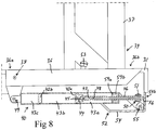
- is a schematic, partly cut, lateral view of parts included in the high seat arrangement of
Figs 2-4 , as seen with the stand in the non-use position, - Figs 9 and 10
- are schematic, partly cut, lateral views corresponding to
Fig 8 , as seen with the stand in the use position, - Fig 11
- is a schematic detail enlargement of a part of a lockable gas spring included in the high seat arrangement of
Figs 2-4 , as seen with a valve member of the lockable gas spring in closed position, - Fig 12
- is a schematic detail enlargement corresponding to
Fig 11 , as seen with the valve member in open position, and - Fig 13
- is an outline diagram of parts included in a load handling crane according to the invention.
- In this description, the expression "liftable and lowerable crane boom" refers to a crane boom which can be pivoted in a vertical plane so as to thereby perform liftings and lowerings of a load carried by the crane. The expression "hydraulic cylinder for lifting and lowering the crane boom" here refers to the hydraulic cylinder which is associated with the liftable and lowerable crane boom and which carries out the pivoting thereof in a vertical plane.
-
Fig 1 shows a hydraulicload handling crane 1 according to an embodiment of the present invention. Thecrane 1 comprises acrane base 4, which is to be connected to the chassis of a vehicle, for instance in the form of a lorry. - The
crane 1 further comprises: - a
column 5, which is rotatably mounted to thecrane base 4 so as to be rotatable in relation to the crane base about an essentially vertical axis of rotation by means of anactuator 6, for instance in the form of a hydraulic cylinder; - a liftable and lowerable
first crane boom 7, here denominated inner boom, which is articulately connected to thecolumn 5 in such a manner that it is pivotable in relation to the column about an essentially horizontal axis of rotation; - a first
hydraulic cylinder 8 for lifting and lowering theinner boom 7 in relation to thecolumn 5; - a liftable and lowerable
second crane boom 9, here denominated outer boom, which is articulately connected to theinner boom 7 in such a manner that it is pivotable in relation to theinner boom 7 about an essentially horizontal axis of rotation; and - a second
hydraulic cylinder 10 for lifting and lowering theouter boom 9 in relation to theinner boom 7. - In the illustrated embodiment, the crane boom system 11 of the
crane 1 is formed by theinner boom 7 and theouter boom 9 and the associatedhydraulic cylinders crane 1 may as an alternative include more than two liftable and lowerable crane booms articulately connected to each other. One or more of the crane booms of the crane boom system 11 may be telescopically extensible, for instance by means of one or more hydraulic cylinders, in order to enable an adjustment of the extension length thereof. - In the illustrated embodiment, the
outer boom 9 is telescopically extensible and comprises a base section 9a and several telescopiccrane boom sections 9b which are mutually slidable in relation to each other in the longitudinal direction of theouter boom 9 for adjustment of the extension length thereof. The telescopiccrane boom sections 9b are displaceable in relation to the base section 9a and in relation to each other by means ofhydraulic cylinders 12 carried by theouter boom 9. - The
load handling crane 1 is provided with asupport leg arrangement 20 for supporting the crane. Thesupport leg arrangement 20 comprises abase structure 21 fixedly connected to thecrane base 4 and at least twosupport legs 22a, 22b moveably mounted to thebase structure 21 on opposite sides of thecrane base 4. In the illustrated embodiment, thesupport leg arrangement 20 comprises afirst support leg 22a provided on a first side of thecrane base 4 and a second support leg 22b provided on an opposite second side of thecrane base 4, wherein eachsupport leg 22a, 22b is moveable in a horizontal direction in relation to thecrane base 4 by means of an actuator (not shown), for instance in the form of a hydraulic cylinder or any other suitable type of linear actuator, between a retracted position close to thebase structure 21 and an extended position (seeFig 1 ) at a further distance from thebase structure 21. In the illustrated embodiment, eachsupport leg 22a, 22b is fixed at the outer end of a telescopically extensible support leg beam 23a, 23b, which is slidably mounted to thebase structure 21 so as to be horizontally moveable in relation to the base structure. Furthermore, eachsupport leg 22a, 22b is telescopically extensible in a vertical direction by means of anactuator foot plate 25a, 25b is provided at the outer end of eachsupport leg 22a, 22b, wherein thisfoot plate 25a, 25b is moveable, by a vertical extension of the support leg, from a non-use position (seeFig 1 ), in which thefoot plate 25a, 25b is lifted from the ground, to an operating position, in which thefoot plate 25a, 25b is in supporting contact with the ground. As an alternative, eachsupport leg 22a, 22b could be pivotally mounted to thebase structure 21 of thesupport leg arrangement 20 so as to be pivotable by means of an actuator, for instance in the form of a hydraulic cylinder, between a non-use position and an operating position. - The
load handling crane 1 is also provided with ahigh seat arrangement 30 comprising ahigh seat platform 31 and an operator'sseat 32 mounted to the high seat platform. The operator'sseat 32 is arranged in the open air on thehigh seat platform 31. Thehigh seat platform 31 is fixedly connected to thecolumn 5 at an elevated position and is rotatable in relation to thecrane base 4 together with thecolumn 5. Thus, thehigh seat platform 31 and the operator'sseat 32 rotate together with the crane boom system 11 and thecolumn 5 about the above-mentioned vertical axis of rotation when thecolumn 5 is rotated in relation to thecrane base 4 by means of theactuator 6. The crane operator may sit on the operator'sseat 32 when controlling the movement of thesupport legs crane booms high seat platform 31, the crane operator has a good view over the operating areas of thesupport legs high seat platform 31 through aladder 33, which is fixedly connected to thecrane base 4. - The
load handling crane 1 comprises aportable manoeuvring unit 60 with one ormore maneuvering members Figs 2-4 ) configured to be manoeuvrable by the crane operator in order to control the movement of thesupport legs 22a, 22b, the rotation of thecolumn 5 and the movement of thecrane booms portable manoeuvring unit 60 to an electronic control device 70 (very schematically illustrated inFig 13 ), which in its turn controls the above-mentioned hydraulic cylinders and actuators of thecrane 1 in a conventional manner in dependence on the control signals from theportable manoeuvring unit 60 related to the manoeuvring of themanoeuvring members electronic control device 70 comprises a microprocessor or the similar for processing the control signals from theportable manoeuvring unit 60. - The
manoeuvring members Figs 2-4 , but any other suitable type of manoeuvring members may also be used, such as for instance toggle levers or the similar. - The
high seat arrangement 30 comprises astand 34, which is mounted to thehigh seat platform 31, and anattachment 35 configured for releasable engagement with theportable manoeuvring unit 60. Theattachment 35 is fixed to thestand 34 and themanoeuvring unit 60 is detachably mountable to theattachment 35 in order to allow themanoeuvring unit 60 to be firmly fixed to and carried by thestand 34. Thestand 34 is capable of positioning theattachment 35 in such a position in front of the operator'sseat 32 that a crane operator sitting on the operator'sseat 32 will be able to manoeuvre themanoeuvring members portable manoeuvring unit 60 in a convenient manner when themanoeuvring unit 60 is mounted to theattachment 35. Thestand 34 is preferably adjustable so as to allow an adjustment of the position of theattachment 35 in relation to the operator'sseat 32. - The
stand 34 is with advantage pivotally mounted to thehigh seat platform 31, wherein thestand 34 is pivotable in relation to thehigh seat platform 31 between a use position (seeFigs 2 and3 ), in which thestand 34 keeps theattachment 35 in an advanced position close to the operator'sseat 32, and a non-use position (seeFig 4 ), in which thestand 34 keeps theattachment 35 in a retracted position further away from the operator'sseat 32. - In the illustrated embodiment, the
stand 34 comprises abase 36 and apillar 37, wherein thebase 36 is pivotally mounted to thehigh seat platform 31 through a joint 38 (seeFigs 8-10 ) which forms a horizontal pivot axis for the stand. Thepillar 37 has a lower end and an upper end, wherein thepillar 37 is fixed to the base 36 at its lower end and theattachment 35 is fixed to the upper end of the pillar. - In the illustrated example, the
base 36 has the form of an elongated bar with a first end 36a and an oppositesecond end 36b, wherein thebase 36 is pivotally mounted to thehigh seat platform 31 at its first end 36a and thepillar 37 is fixed to the base 36 at thesecond end 36b thereof. Thepillar 37 is preferably fixed to the base 36 with the longitudinal axis of thepillar 37 extending perpendicularly to the longitudinal axis of thebase 36. - The
pillar 37 is with advantage telescopically extensible in order to allow an adjustment of the vertical position of theattachment 35 by an adjustment of the length of the pillar. In the illustrated embodiment, thepillar 37 comprises a lower pillar part 37a (seeFigs 3 and6 ) and an upper pillar part 37b, wherein the upper pillar part 37b is telescopically connected to the lower pillar part 37a and axially moveable into different displacement positions in relation to the lower pillar part 37a in order to allow an adjustment of the length of thepillar 37. The upper pillar part 37b is lockable to the lower pillar part 37a in a desired displacement position by means of a manuallymanoeuvrable locking mechanism 38. - The
attachment 35 is with advantage pivotally connected to the upper end of thepillar 37 and moveable into different pivotal positions in relation to thepillar 37 in order to allow an adjustment of the inclination of theattachment 35 in relation to thepillar 37 and thereby an adjustment of the inclination of theattachment 35 in relation to the operator'sseat 32. Theattachment 35 is lockable to thepillar 37 in a desired pivotal position by means of a manuallymanoeuvrable locking mechanism 39. - In the illustrated embodiment, the
attachment 35 comprises two pin-shapedattachment members 35a, 35b, which are insertable into a respective recess 63a, 63b provided in ahousing 64 of theportable manoeuvring unit 60, as illustrated inFigs 5 and 6 . However, theattachment 35 may of course also be configured to engage with theportable manoeuvring unit 60 in any other suitable manner. - In the illustrated embodiment, the
stand 34 is biased towards the non-use position by a lockable gas spring 40 (seeFigs 7-12 ) of a conventional type, wherein thestand 34 is pivotable from the non-use position to the use position against the action of thelockable gas spring 40 and pivotable from the use position to the non-use position under the action of thelockable gas spring 40. - The
lockable gas spring 40 comprises: - a
cylinder part 41; - a
first piston 42a received in thecylinder part 41; - first and
second fluid chambers cylinder part 41 and separated from each other by thefirst piston 42a, wherein thefluid chambers fluid passage 44 in thefirst piston 42a; - a
valve member 45 arranged in thefirst piston 42a, wherein thevalve member 45 is moveable between an open position, in which thevalve member 45 keeps thefluid passage 44 open and thereby allows fluid to flow between thefluid chambers valve member 45 blocks thefluid passage 44 and thereby prevents fluid from flowing between thefluid chambers - a
piston rod 46 fixed to thefirst piston 42a and extending through the firstfluid chamber 43a; - an operating
rod 47 for controlling thevalve member 45, the operating rod extending through anaxial bore 48 in thepiston rod 46 and being operatively connected to thevalve member 45; - a
second piston 42b received in thecylinder part 41; and - a gas chamber 43c which is provided in the
cylinder part 41 and separated from the secondfluid chamber 43b by thesecond piston 42b. - The
piston rod 46 extends through a seal 59a and a guide member 59b provided at the end of thecylinder part 41. - The first and
second fluid chambers - Under the effect of an external force, the operating
rod 47 is moveable in relation to thepiston rod 46 from a first position (seeFigs 8 ,9 and11 ), in which thevalve member 45 is in the closed position, to a second position (seeFigs 10 and12 ), in which the operatingrod 47 keeps thevalve member 45 in the open position. When thevalve member 45 is in the closed position, no fluid is allowed to flow between thefluid chambers cylinder part 41 is thereby prevented from moving axially in relation to thepiston rod 46. When thevalve member 45 is in the open position, fluid is allowed to flow between thefluid chambers cylinder part 41 is thereby allowed to move axially in relation to thepiston rod 46. When the external force on the operatingrod 47 is released, thevalve member 45 returns from the open position to the closed position under the effect of the pressure from the fluid in thefluid chamber 43b on the piston side of thelockable gas spring 40. - The illustrated
gas spring 40 is a lockable gas spring of a type which is rigid in compression, but thegas spring 40 could as an alternative be a lockable gas spring of any other suitable type. - The
cylinder part 41 of thelockable gas spring 40 is articulately connected to thebase 36 of thestand 34 through a joint 49, which forms a horizontal pivot axis between thestand 34 and thelockable gas spring 40. Thepiston rod 46 of thelockable gas spring 40 is articulately connected to thehigh seat platform 31 through a joint 50, which forms a horizontal pivot axis between thehigh seat platform 31 and thelockable gas spring 40. The last-mentioned joint 50 is formed by apivot member 51, which is rotatably mounted to thehigh seat platform 31, wherein the outer end of thepiston rod 46 is firmly fixed to thispivot member 51. - The
high seat arrangement 30 comprises amanoeuvring mechanism 52 which is operatively connected to the operatingrod 47 of thelockable gas spring 40, wherein a crane operator sitting on the operator'sseat 32 is capable of exerting a pushing force on the operatingrod 47 by means of themanoeuvring mechanism 52 in order to move the operating rod from the above-mentioned first position to the above-mentioned second position. In the illustrated embodiment, themanoeuvring mechanism 52 comprises afoot lever 53 arranged on thehigh seat platform 31 and amotion transferring member 54 for transferring a depression of thefoot lever 53 into a movement of the operatingrod 47 from the first position to the second position. Thefoot lever 53 is arranged within reach for a crane operator sitting on the operator'sseat 32. Themotion transferring member 54 is pivotally mounted to thehigh seat platform 31 through a joint 55 which forms a horizontal pivot axis for themotion transferring member 54. Thefoot lever 53 is fixed to afirst end 54a (seeFig 7 ) of themotion transferring member 54 and the operatingrod 47 is in contact with a contact surface 56 (seeFig 8 ) at an oppositesecond end 54b of themotion transferring member 54. In the illustrated example, themotion transferring member 54 has the form of an elongated and angled plate, but it may of course be designed in any other suitable manner. The crane operator may effect a movement of thevalve member 45 to the open position by depressing thefoot lever 53. As long as thefoot lever 53 remains in the depressed position, the crane operator may manually pivot thestand 34 to a desired pivotal position in order to position theportable manoeuvring unit 60 in a suitable position in front of the operator'sseat 32. When the crane operator releases thefoot lever 53, thevalve member 45 returns to the closed position and thestand 34 is thereby locked in its prevailing position. The crane operator may later on effect an automatic return of thestand 34 to the non-use position by depressing thefoot lever 53 and keeping it depressed for a short period of time, which will cause thelockable gas spring 40 to expand under the effect of the pressure from the fluid in thefluid chamber 43b on the piston side of the lockable gas spring. - A manually activatable
first confirmation member 26a (seeFigs 1 and13 ) is accessible on the first side of thecrane base 4, wherein theelectronic control device 70 is configured to allow thefirst support leg 22a to be moved under the control of theportable manoeuvring unit 60 when theelectronic control device 70 has received a confirmation signal indicating that thefirst confirmation member 26a has been manually activated. A manually activatablesecond confirmation member 26b (very schematically illustrated inFig 13 ) is accessible on the opposite second side of thecrane base 4, wherein theelectronic control device 70 is configured to allow the second support leg 22b to be moved under the control of theportable manoeuvring unit 60 when theelectronic control device 70 has received a confirmation signal indicating that thesecond confirmation member 26b has been manually activated. Eachconfirmation member - The
high seat arrangement 30 comprises a detecting device 57 (very schematically illustrated inFig 13 ) for detecting the mounting of theportable manoeuvring unit 60 to theattachment 35 on thestand 34, wherein theelectronic control device 70 is configured to allow the first andsecond support legs 22a, 22b to be moved under the control of theportable manoeuvring unit 60 when theelectronic control device 70 has received a detecting signal from the detectingdevice 57 indicating that theportable manoeuvring unit 60 has been mounted to theattachment 35. The detectingdevice 57 may for instance comprise aproximity sensor 58, which is arranged on theattachment 35 and configured to sense the presence of theportable manoeuvring unit 60 when the portable manoeuvring unit has been mounted to theattachment 35. However, the detectingdevice 57 may also comprise any other suitable type of sensor for detecting the mounting of theportable manoeuvring unit 60 to theattachment 35, such as for instance a micro switch. - The
electronic control device 70 is configured to prevent the first andsecond support legs 22a, 22b from being moved under the control of theportable manoeuvring unit 60 when theelectronic control device 70 has not received any confirmation signal indicating that the first orsecond confirmation member device 57 indicating that theportable manoeuvring unit 60 has been mounted to theattachment 35. Thus, thesupport leg 22a on the first side of thecrane base 4 may only be moved under the control of theportable manoeuvring unit 60 when theconfirmation member 26a on the first side of thecrane base 4 has been manually activated or when it is detected by the detectingdevice 57 that theportable manoeuvring unit 60 is mounted to theattachment 35 on thestand 34. In the corresponding manner, the support leg 22b on the second side of thecrane base 4 may only be moved under the control of theportable manoeuvring unit 60 when theconfirmation member 26b on the second side of thecrane base 4 has been manually activated or when it is detected by the detectingdevice 57 that theportable manoeuvring unit 60 is mounted to theattachment 35 on thestand 34. - The invention is of course not in any way limited to the embodiments described above. On the contrary, several possibilities to modifications thereof should be apparent to a person skilled in the art without thereby deviating from the basic idea of the invention as defined in the appended claims.
Claims (15)
- A load handling crane comprising:- a crane base (4);- a column (5) which is rotatably mounted to the crane base (4) so as to be rotatable in relation to the crane base about an essentially vertical axis of rotation;- an actuator (6) for rotating the column (5);- a crane boom system (11) comprising two or more liftable and lowerable crane booms (7, 9), which are articulately connected to each other, and hydraulic cylinders (8, 10) for lifting and lowering the crane booms (7, 9), wherein a first crane boom (7) of the crane boom system is articulately connected to the column (5) and a second crane boom (9) of the crane boom system is articulately connected to the first crane boom (7);- an electronic control device (70) for controlling said actuator (6) and said hydraulic cylinders (8, 10) so as to control the rotation of the column (5) and the movement of the crane booms (7, 9);- a portable manoeuvring unit (60) with one or more manoeuvring members (61 a, 61 b) configured to be manoeuvrable by a crane operator in order to control the position of the crane booms (7, 9), wherein the portable manoeuvring unit (60) is configured to transmit control signals to the electronic control device (70) related to the manoeuvring of said manoeuvring members (61 a, 61 b); and- a high seat arrangement (30) comprising a high seat platform (31) and an operator's seat (32), wherein the high seat platform (31) is connected to the column (5) so as to be rotatable in relation to the crane base (4) together with the column, and wherein the operator's seat (32) is mounted to the high seat platform (31),characterized in:- that the high seat arrangement (30) comprises a stand (34), which is mounted to the high seat platform (31), and an attachment (35) configured for releasable engagement with the portable manoeuvring unit (60), wherein the attachment (35) is fixed to the stand (34) and wherein the manoeuvring unit (60) is detachably mountable to the attachment (35) in order to allow the manoeuvring unit (60) to be carried by the stand (34); and- that the stand (34) is configured to position the attachment (35) in such a position in front of the operator's seat (32) that a crane operator sitting on the operator's seat (32) is allowed to manoeuvre said manoeuvring members (61a, 61 b) on the portable manoeuvring unit (60) when it is mounted to the attachment (35).
- A load handling crane according to claim 1, characterized in that the stand (34) is pivotally mounted to the high seat platform (31), wherein the stand (34) is pivotable in relation to the high seat platform (31) between a use position, in which the stand (34) keeps said attachment (35) in an advanced position close to the operator's seat (32), and a non-use position, in which the stand (34) keeps said attachment (35) in a retracted position further away from the operator's seat (32).
- A load handling crane according to claim 2, characterized in:- that the stand (34) comprises a base (36) and a pillar (37), wherein the base (36) is pivotally mounted to the high seat platform (31) through a joint (38) which forms a horizontal pivot axis for the stand (34); and- that the pillar (37) has a lower end and an upper end, wherein the pillar (37) is fixed to the base (36) at its lower end and said attachment (35) is fixed to the upper end of the pillar.
- A load handling crane according to claim 3, characterized in that the base (36) has the form of an elongated bar with a first end (36a) and an opposite second end (36b), wherein the base (36) is pivotally mounted to the high seat platform (31) at its first end (36a) and the pillar (37) is fixed to the base (36) at the second end (36b) thereof.
- A load handling crane according to claim 4, characterized in that the pillar (37) is fixed to the base (36) with the longitudinal axis of the pillar extending perpendicularly to the longitudinal axis of the base (36).
- A load handling crane according to any of claims 3-5, characterized in that the pillar (37) is telescopically extensible in order to allow an adjustment of the vertical position of said attachment (35) by an adjustment of the length of the pillar.
- A load handling crane according to any of claims 3-6, characterized in that said attachment (35) is pivotally connected to the upper end of the pillar (37) and moveable into different pivotal positions in relation to the pillar (37) in order to allow an adjustment of the inclination of the attachment (35) in relation to the pillar (37) and thereby an adjustment of the inclination of the attachment (35) in relation to the operator's seat (32), wherein the attachment (35) is lockable to the pillar (37) in a desired pivotal position by means of a locking mechanism (39).
- A load handling crane according to any of claims 2-7, characterized in that the stand (34) is biased towards the non-use position by a lockable gas spring (40), wherein the stand (34) is pivotable from the non-use position to the use position against the action of the lockable gas spring (40) and pivotable from the use position to the non-use position under the action of the lockable gas spring (40).
- A load handling crane according to claim 8, characterized in that the lockable gas spring (40) comprises:- a cylinder part (41);- a piston (42a) received in the cylinder part (41);- two separate fluid chambers (43a, 43b) which are provided in the cylinder part (41) and separated from each other by the piston (42a), wherein the fluid chambers (43a, 43b) are filled with a fluid and are fluidly connectable to each other via a fluid passage (44) in the piston (42a);- a valve member (45) arranged in the piston (42a), wherein the valve member (45) is moveable between an open position, in which the valve member keeps the fluid passage (44) open and thereby allows fluid to flow between said fluid chambers (43a, 43b), and a closed position, in which the valve member (45) blocks the fluid passage (44) and thereby prevents fluid from flowing between said fluid chambers (43a, 43b);- a piston rod (46) fixed to the piston (42a); and- an operating rod (47) for controlling the valve member (45), the operating rod extending through an axial bore (48) in the piston rod (46) and being operatively connected to the valve member (45), wherein the operating rod (47), under the effect of an external force, is moveable in relation to the piston rod (46) from a first position, in which the valve member (45) is in the closed position, to a second position, in which the operating rod (47) keeps the valve member (45) in the open position.
- A load handling crane according to claim 9, characterized in that the high seat arrangement (30) comprises a manoeuvring mechanism (52) which is operatively connected to the operating rod (47) of the lockable gas spring (40), wherein a crane operator sitting on the operator's seat (32) is allowed to exert a force on the operating rod (47) by means of the manoeuvring mechanism (52) in order to move the operating rod from said first position to said second position.
- A load handling crane according to claim 10, characterized in that the manoeuvring mechanism (52) comprises:- a foot lever (53) arranged on the high seat platform (31); and- a motion transferring member (54) for transferring a depression of the foot lever (53) into a movement of the operating rod (47) from said first position to said second position.
- A load handling crane according to claim 11, characterized in that the motion transferring member (54) is pivotally mounted to the high seat platform (31) and has a first end (54a) and an opposite second end (54b), wherein the foot lever (53) is fixed to the first end (54a) of the motion transferring member (54) and the operating rod (47) is in contact with a contact surface (56) at the second end (54b) of the motion transferring member (54).
- A load handling crane according to claim 12, characterized in that the motion transferring member (54) has the form of an elongated and angled plate.
- A load handling crane according to any of claims 1-13, characterized in:- that the load handling crane (1) comprises a first support leg (22a) arranged on a first side of the crane base (4), a second support leg (22b) arranged on an opposite second side of the crane base (4), one or more first actuators for moving the first support leg (22a) in relation to the crane base (4) and one or more second actuators for moving the second support leg (22b) in relation to the crane base (4), wherein the electronic control device (70) is configured to control the first and second actuators to thereby allow a crane operator to control the movement of the first and second support legs (22a, 22b) via the portable manoeuvring unit (60);- that a manually activatable first confirmation member (26a) is accessible on the first side of the crane base (4), wherein the electronic control device (70) is configured to allow the first support leg (22a) to be moved under the control of the portable manoeuvring unit (60) when the electronic control device (70) has received a confirmation signal indicating that the first confirmation member (26a) has been manually activated;- that a manually activatable second confirmation member (26b) is accessible on the second side of the crane base (4), wherein the electronic control device (70) is configured to allow the second support leg (22b) to be moved under the control of the portable manoeuvring unit (60) when the electronic control device (70) has received a confirmation signal indicating that the second confirmation member (26b) has been manually activated;- that the high seat arrangement (30) comprises a detecting device (57) for detecting the mounting of the portable manoeuvring unit (60) to said attachment (35);- that the electronic control device (70) is configured to allow the first and second support legs (22a, 22b) to be moved under the control of the portable manoeuvring unit (60) when the electronic control device (70) has received a detecting signal from the detecting device (57) indicating that the portable manoeuvring unit (60) has been mounted to said attachment (35); and- that the electronic control device (70) is configured to prevent the first and second support legs (22a, 22b) from being moved under the control of the portable manoeuvring unit (60) when the electronic control device (70) has not received any confirmation signal indicating that the first or second confirmation member (26a, 26b) has been manually activated or any detecting signal indicating that the portable manoeuvring unit (60) has been mounted to said attachment (35).
- A load handling crane according to claim 14, characterized in that the detecting device (57) comprises a proximity sensor (58), which is arranged on said attachment (35) and configured to sense the presence of the portable manoeuvring unit (60) when the portable manoeuvring unit has been mounted to the attachment (35).
Priority Applications (3)
| Application Number | Priority Date | Filing Date | Title |
|---|---|---|---|
| DK17176206.5T DK3415460T3 (en) | 2017-06-15 | 2017-06-15 | HIGH SEAT AND PORTABLE MANUAL LOADING CRANE |
| EP17176206.5A EP3415460B1 (en) | 2017-06-15 | 2017-06-15 | Load handling crane with high seat and portable manoeuvring unit |
| PCT/EP2018/062688 WO2018228768A1 (en) | 2017-06-15 | 2018-05-16 | Load handling crane |
Applications Claiming Priority (1)
| Application Number | Priority Date | Filing Date | Title |
|---|---|---|---|
| EP17176206.5A EP3415460B1 (en) | 2017-06-15 | 2017-06-15 | Load handling crane with high seat and portable manoeuvring unit |
Publications (2)
| Publication Number | Publication Date |
|---|---|
| EP3415460A1 true EP3415460A1 (en) | 2018-12-19 |
| EP3415460B1 EP3415460B1 (en) | 2020-03-11 |
Family
ID=59067580
Family Applications (1)
| Application Number | Title | Priority Date | Filing Date |
|---|---|---|---|
| EP17176206.5A Active EP3415460B1 (en) | 2017-06-15 | 2017-06-15 | Load handling crane with high seat and portable manoeuvring unit |
Country Status (3)
| Country | Link |
|---|---|
| EP (1) | EP3415460B1 (en) |
| DK (1) | DK3415460T3 (en) |
| WO (1) | WO2018228768A1 (en) |
Cited By (1)
| Publication number | Priority date | Publication date | Assignee | Title |
|---|---|---|---|---|
| EP4640614A1 (en) | 2024-04-26 | 2025-10-29 | Hiab AB | Working equipment provided with means for reducing impact of movements when controlling the working equipment |
Citations (4)
| Publication number | Priority date | Publication date | Assignee | Title |
|---|---|---|---|---|
| WO2003086940A1 (en) * | 2002-04-18 | 2003-10-23 | Jonsered Cranes Ab | A holding unit related to a crane arrangement |
| TWI232842B (en) * | 2003-11-18 | 2005-05-21 | De-Shuei Tsai | Curved arm type hydraulic hanging device |
| WO2008143584A1 (en) * | 2007-05-23 | 2008-11-27 | Cargotec Patenter Ab | Hydraulic crane and a method for regulating the maximum allowed working pressure in such a crane |
| WO2009010818A2 (en) * | 2007-07-17 | 2009-01-22 | Volvo Compact Equipment Sas | Construction equipment machine comprising a cabin with advanced ergonomics |
-
2017
- 2017-06-15 DK DK17176206.5T patent/DK3415460T3/en active
- 2017-06-15 EP EP17176206.5A patent/EP3415460B1/en active Active
-
2018
- 2018-05-16 WO PCT/EP2018/062688 patent/WO2018228768A1/en not_active Ceased
Patent Citations (4)
| Publication number | Priority date | Publication date | Assignee | Title |
|---|---|---|---|---|
| WO2003086940A1 (en) * | 2002-04-18 | 2003-10-23 | Jonsered Cranes Ab | A holding unit related to a crane arrangement |
| TWI232842B (en) * | 2003-11-18 | 2005-05-21 | De-Shuei Tsai | Curved arm type hydraulic hanging device |
| WO2008143584A1 (en) * | 2007-05-23 | 2008-11-27 | Cargotec Patenter Ab | Hydraulic crane and a method for regulating the maximum allowed working pressure in such a crane |
| WO2009010818A2 (en) * | 2007-07-17 | 2009-01-22 | Volvo Compact Equipment Sas | Construction equipment machine comprising a cabin with advanced ergonomics |
Cited By (1)
| Publication number | Priority date | Publication date | Assignee | Title |
|---|---|---|---|---|
| EP4640614A1 (en) | 2024-04-26 | 2025-10-29 | Hiab AB | Working equipment provided with means for reducing impact of movements when controlling the working equipment |
Also Published As
| Publication number | Publication date |
|---|---|
| WO2018228768A1 (en) | 2018-12-20 |
| EP3415460B1 (en) | 2020-03-11 |
| DK3415460T3 (en) | 2020-06-02 |
Similar Documents
| Publication | Publication Date | Title |
|---|---|---|
| KR102219605B1 (en) | Tripod for supporting of fire fighting hose | |
| CA2602688C (en) | Lever-actuated retractable wheel and movable platform using same | |
| JP4286183B2 (en) | Armrest device | |
| JP6764477B2 (en) | Mobile crane | |
| WO2019055668A1 (en) | Tilting bucket | |
| EP1778156B1 (en) | Patient lift with integrated foot push pad | |
| CN114408820A (en) | Aerial work platform | |
| EP3415460B1 (en) | Load handling crane with high seat and portable manoeuvring unit | |
| US20100171278A1 (en) | Elevated work platform and multi-function tool | |
| WO1994007397A1 (en) | Computer work station | |
| JP2009269719A (en) | Vehicle for high lift work | |
| JP5279258B2 (en) | Altitude work equipment | |
| JP2009143662A (en) | Altitude work equipment | |
| JP4625686B2 (en) | Work vehicle safety control device | |
| JP2006160502A (en) | Work vehicle safety control device | |
| JPS6111336Y2 (en) | ||
| US20260070520A1 (en) | Compact outrigger device | |
| JPH10236798A (en) | Boom operation control device | |
| JP2003321197A (en) | Safety equipment for aerial work vehicles | |
| JP4856812B2 (en) | Control device for work equipment | |
| JP2510310Y2 (en) | Boom and workbench storage safety device for aerial work platforms | |
| JP3787089B2 (en) | Boom operation control device | |
| JP3768037B2 (en) | Boom work vehicle leveling system | |
| KR100977129B1 (en) | Control lever auxiliary device of heavy construction equipment | |
| GB2297962A (en) | Lifting Devices |
Legal Events
| Date | Code | Title | Description |
|---|---|---|---|
| PUAI | Public reference made under article 153(3) epc to a published international application that has entered the european phase |
Free format text: ORIGINAL CODE: 0009012 |
|
| STAA | Information on the status of an ep patent application or granted ep patent |
Free format text: STATUS: THE APPLICATION HAS BEEN PUBLISHED |
|
| AK | Designated contracting states |
Kind code of ref document: A1 Designated state(s): AL AT BE BG CH CY CZ DE DK EE ES FI FR GB GR HR HU IE IS IT LI LT LU LV MC MK MT NL NO PL PT RO RS SE SI SK SM TR |
|
| AX | Request for extension of the european patent |
Extension state: BA ME |
|
| STAA | Information on the status of an ep patent application or granted ep patent |
Free format text: STATUS: REQUEST FOR EXAMINATION WAS MADE |
|
| 17P | Request for examination filed |
Effective date: 20190517 |
|
| RBV | Designated contracting states (corrected) |
Designated state(s): AL AT BE BG CH CY CZ DE DK EE ES FI FR GB GR HR HU IE IS IT LI LT LU LV MC MK MT NL NO PL PT RO RS SE SI SK SM TR |
|
| REG | Reference to a national code |
Ref country code: DE Ref legal event code: R079 Ref document number: 602017012809 Country of ref document: DE Free format text: PREVIOUS MAIN CLASS: B66C0013560000 Ipc: B66C0013400000 |
|
| RIC1 | Information provided on ipc code assigned before grant |
Ipc: B66C 13/40 20060101AFI20190814BHEP Ipc: B66C 23/00 20060101ALI20190814BHEP |
|
| GRAP | Despatch of communication of intention to grant a patent |
Free format text: ORIGINAL CODE: EPIDOSNIGR1 |
|
| STAA | Information on the status of an ep patent application or granted ep patent |
Free format text: STATUS: GRANT OF PATENT IS INTENDED |
|
| INTG | Intention to grant announced |
Effective date: 20191007 |
|
| GRAS | Grant fee paid |
Free format text: ORIGINAL CODE: EPIDOSNIGR3 |
|
| GRAA | (expected) grant |
Free format text: ORIGINAL CODE: 0009210 |
|
| STAA | Information on the status of an ep patent application or granted ep patent |
Free format text: STATUS: THE PATENT HAS BEEN GRANTED |
|
| AK | Designated contracting states |
Kind code of ref document: B1 Designated state(s): AL AT BE BG CH CY CZ DE DK EE ES FI FR GB GR HR HU IE IS IT LI LT LU LV MC MK MT NL NO PL PT RO RS SE SI SK SM TR |
|
| RAP1 | Party data changed (applicant data changed or rights of an application transferred) |
Owner name: CARGOTEC PATENTER AB |
|
| REG | Reference to a national code |
Ref country code: GB Ref legal event code: FG4D |
|
| REG | Reference to a national code |
Ref country code: CH Ref legal event code: EP |
|
| REG | Reference to a national code |
Ref country code: AT Ref legal event code: REF Ref document number: 1242915 Country of ref document: AT Kind code of ref document: T Effective date: 20200315 |
|
| REG | Reference to a national code |
Ref country code: IE Ref legal event code: FG4D |
|
| REG | Reference to a national code |
Ref country code: DE Ref legal event code: R096 Ref document number: 602017012809 Country of ref document: DE |
|
| REG | Reference to a national code |
Ref country code: DK Ref legal event code: T3 Effective date: 20200531 |
|
| PG25 | Lapsed in a contracting state [announced via postgrant information from national office to epo] |
Ref country code: RS Free format text: LAPSE BECAUSE OF FAILURE TO SUBMIT A TRANSLATION OF THE DESCRIPTION OR TO PAY THE FEE WITHIN THE PRESCRIBED TIME-LIMIT Effective date: 20200311 Ref country code: FI Free format text: LAPSE BECAUSE OF FAILURE TO SUBMIT A TRANSLATION OF THE DESCRIPTION OR TO PAY THE FEE WITHIN THE PRESCRIBED TIME-LIMIT Effective date: 20200311 Ref country code: NO Free format text: LAPSE BECAUSE OF FAILURE TO SUBMIT A TRANSLATION OF THE DESCRIPTION OR TO PAY THE FEE WITHIN THE PRESCRIBED TIME-LIMIT Effective date: 20200611 |
|
| REG | Reference to a national code |
Ref country code: NL Ref legal event code: MP Effective date: 20200311 |
|
| PG25 | Lapsed in a contracting state [announced via postgrant information from national office to epo] |
Ref country code: SE Free format text: LAPSE BECAUSE OF FAILURE TO SUBMIT A TRANSLATION OF THE DESCRIPTION OR TO PAY THE FEE WITHIN THE PRESCRIBED TIME-LIMIT Effective date: 20200311 Ref country code: LV Free format text: LAPSE BECAUSE OF FAILURE TO SUBMIT A TRANSLATION OF THE DESCRIPTION OR TO PAY THE FEE WITHIN THE PRESCRIBED TIME-LIMIT Effective date: 20200311 Ref country code: GR Free format text: LAPSE BECAUSE OF FAILURE TO SUBMIT A TRANSLATION OF THE DESCRIPTION OR TO PAY THE FEE WITHIN THE PRESCRIBED TIME-LIMIT Effective date: 20200612 Ref country code: HR Free format text: LAPSE BECAUSE OF FAILURE TO SUBMIT A TRANSLATION OF THE DESCRIPTION OR TO PAY THE FEE WITHIN THE PRESCRIBED TIME-LIMIT Effective date: 20200311 Ref country code: BG Free format text: LAPSE BECAUSE OF FAILURE TO SUBMIT A TRANSLATION OF THE DESCRIPTION OR TO PAY THE FEE WITHIN THE PRESCRIBED TIME-LIMIT Effective date: 20200611 |
|
| REG | Reference to a national code |
Ref country code: LT Ref legal event code: MG4D |
|
| PG25 | Lapsed in a contracting state [announced via postgrant information from national office to epo] |
Ref country code: NL Free format text: LAPSE BECAUSE OF FAILURE TO SUBMIT A TRANSLATION OF THE DESCRIPTION OR TO PAY THE FEE WITHIN THE PRESCRIBED TIME-LIMIT Effective date: 20200311 |
|
| PG25 | Lapsed in a contracting state [announced via postgrant information from national office to epo] |
Ref country code: IS Free format text: LAPSE BECAUSE OF FAILURE TO SUBMIT A TRANSLATION OF THE DESCRIPTION OR TO PAY THE FEE WITHIN THE PRESCRIBED TIME-LIMIT Effective date: 20200711 Ref country code: CZ Free format text: LAPSE BECAUSE OF FAILURE TO SUBMIT A TRANSLATION OF THE DESCRIPTION OR TO PAY THE FEE WITHIN THE PRESCRIBED TIME-LIMIT Effective date: 20200311 Ref country code: SK Free format text: LAPSE BECAUSE OF FAILURE TO SUBMIT A TRANSLATION OF THE DESCRIPTION OR TO PAY THE FEE WITHIN THE PRESCRIBED TIME-LIMIT Effective date: 20200311 Ref country code: RO Free format text: LAPSE BECAUSE OF FAILURE TO SUBMIT A TRANSLATION OF THE DESCRIPTION OR TO PAY THE FEE WITHIN THE PRESCRIBED TIME-LIMIT Effective date: 20200311 Ref country code: PT Free format text: LAPSE BECAUSE OF FAILURE TO SUBMIT A TRANSLATION OF THE DESCRIPTION OR TO PAY THE FEE WITHIN THE PRESCRIBED TIME-LIMIT Effective date: 20200805 Ref country code: LT Free format text: LAPSE BECAUSE OF FAILURE TO SUBMIT A TRANSLATION OF THE DESCRIPTION OR TO PAY THE FEE WITHIN THE PRESCRIBED TIME-LIMIT Effective date: 20200311 Ref country code: EE Free format text: LAPSE BECAUSE OF FAILURE TO SUBMIT A TRANSLATION OF THE DESCRIPTION OR TO PAY THE FEE WITHIN THE PRESCRIBED TIME-LIMIT Effective date: 20200311 Ref country code: SM Free format text: LAPSE BECAUSE OF FAILURE TO SUBMIT A TRANSLATION OF THE DESCRIPTION OR TO PAY THE FEE WITHIN THE PRESCRIBED TIME-LIMIT Effective date: 20200311 |
|
| REG | Reference to a national code |
Ref country code: DE Ref legal event code: R097 Ref document number: 602017012809 Country of ref document: DE |
|
| PLBE | No opposition filed within time limit |
Free format text: ORIGINAL CODE: 0009261 |
|
| STAA | Information on the status of an ep patent application or granted ep patent |
Free format text: STATUS: NO OPPOSITION FILED WITHIN TIME LIMIT |
|
| PG25 | Lapsed in a contracting state [announced via postgrant information from national office to epo] |
Ref country code: MC Free format text: LAPSE BECAUSE OF FAILURE TO SUBMIT A TRANSLATION OF THE DESCRIPTION OR TO PAY THE FEE WITHIN THE PRESCRIBED TIME-LIMIT Effective date: 20200311 Ref country code: ES Free format text: LAPSE BECAUSE OF FAILURE TO SUBMIT A TRANSLATION OF THE DESCRIPTION OR TO PAY THE FEE WITHIN THE PRESCRIBED TIME-LIMIT Effective date: 20200311 |
|
| REG | Reference to a national code |
Ref country code: CH Ref legal event code: PL |
|
| 26N | No opposition filed |
Effective date: 20201214 |
|
| PG25 | Lapsed in a contracting state [announced via postgrant information from national office to epo] |
Ref country code: PL Free format text: LAPSE BECAUSE OF FAILURE TO SUBMIT A TRANSLATION OF THE DESCRIPTION OR TO PAY THE FEE WITHIN THE PRESCRIBED TIME-LIMIT Effective date: 20200311 Ref country code: SI Free format text: LAPSE BECAUSE OF FAILURE TO SUBMIT A TRANSLATION OF THE DESCRIPTION OR TO PAY THE FEE WITHIN THE PRESCRIBED TIME-LIMIT Effective date: 20200311 |
|
| REG | Reference to a national code |
Ref country code: DE Ref legal event code: R082 Ref document number: 602017012809 Country of ref document: DE Representative=s name: MANITZ FINSTERWALD PATENT- UND RECHTSANWALTSPA, DE Ref country code: DE Ref legal event code: R081 Ref document number: 602017012809 Country of ref document: DE Owner name: HIAB AB, SE Free format text: FORMER OWNER: CARGOTEC PATENTER AB, LJUNGBY, SE |
|
| PG25 | Lapsed in a contracting state [announced via postgrant information from national office to epo] |
Ref country code: LU Free format text: LAPSE BECAUSE OF NON-PAYMENT OF DUE FEES Effective date: 20200615 |
|
| REG | Reference to a national code |
Ref country code: BE Ref legal event code: MM Effective date: 20200630 |
|
| PG25 | Lapsed in a contracting state [announced via postgrant information from national office to epo] |
Ref country code: FR Free format text: LAPSE BECAUSE OF NON-PAYMENT OF DUE FEES Effective date: 20200630 Ref country code: IE Free format text: LAPSE BECAUSE OF NON-PAYMENT OF DUE FEES Effective date: 20200615 Ref country code: CH Free format text: LAPSE BECAUSE OF NON-PAYMENT OF DUE FEES Effective date: 20200630 Ref country code: LI Free format text: LAPSE BECAUSE OF NON-PAYMENT OF DUE FEES Effective date: 20200630 |
|
| PG25 | Lapsed in a contracting state [announced via postgrant information from national office to epo] |
Ref country code: BE Free format text: LAPSE BECAUSE OF NON-PAYMENT OF DUE FEES Effective date: 20200630 |
|
| REG | Reference to a national code |
Ref country code: AT Ref legal event code: PC Ref document number: 1242915 Country of ref document: AT Kind code of ref document: T Owner name: HIAB AB, SE Effective date: 20210511 |
|
| GBPC | Gb: european patent ceased through non-payment of renewal fee |
Effective date: 20210615 |
|
| REG | Reference to a national code |
Ref country code: AT Ref legal event code: UEP Ref document number: 1242915 Country of ref document: AT Kind code of ref document: T Effective date: 20200311 |
|
| PG25 | Lapsed in a contracting state [announced via postgrant information from national office to epo] |
Ref country code: GB Free format text: LAPSE BECAUSE OF NON-PAYMENT OF DUE FEES Effective date: 20210615 |
|
| PG25 | Lapsed in a contracting state [announced via postgrant information from national office to epo] |
Ref country code: TR Free format text: LAPSE BECAUSE OF FAILURE TO SUBMIT A TRANSLATION OF THE DESCRIPTION OR TO PAY THE FEE WITHIN THE PRESCRIBED TIME-LIMIT Effective date: 20200311 Ref country code: MT Free format text: LAPSE BECAUSE OF FAILURE TO SUBMIT A TRANSLATION OF THE DESCRIPTION OR TO PAY THE FEE WITHIN THE PRESCRIBED TIME-LIMIT Effective date: 20200311 Ref country code: CY Free format text: LAPSE BECAUSE OF FAILURE TO SUBMIT A TRANSLATION OF THE DESCRIPTION OR TO PAY THE FEE WITHIN THE PRESCRIBED TIME-LIMIT Effective date: 20200311 |
|
| PG25 | Lapsed in a contracting state [announced via postgrant information from national office to epo] |
Ref country code: MK Free format text: LAPSE BECAUSE OF FAILURE TO SUBMIT A TRANSLATION OF THE DESCRIPTION OR TO PAY THE FEE WITHIN THE PRESCRIBED TIME-LIMIT Effective date: 20200311 Ref country code: AL Free format text: LAPSE BECAUSE OF FAILURE TO SUBMIT A TRANSLATION OF THE DESCRIPTION OR TO PAY THE FEE WITHIN THE PRESCRIBED TIME-LIMIT Effective date: 20200311 |
|
| REG | Reference to a national code |
Ref country code: DE Ref legal event code: R081 Ref document number: 602017012809 Country of ref document: DE Owner name: HIAB AB, SE Free format text: FORMER OWNER: HIAB AB, KISTA, SE |
|
| PGFP | Annual fee paid to national office [announced via postgrant information from national office to epo] |
Ref country code: DK Payment date: 20260622 Year of fee payment: 10 |
|
| PGFP | Annual fee paid to national office [announced via postgrant information from national office to epo] |
Ref country code: IT Payment date: 20260623 Year of fee payment: 10 |
|
| PGFP | Annual fee paid to national office [announced via postgrant information from national office to epo] |
Ref country code: DE Payment date: 20260623 Year of fee payment: 10 |
|
| PGFP | Annual fee paid to national office [announced via postgrant information from national office to epo] |
Ref country code: AT Payment date: 20260617 Year of fee payment: 10 |