EP3415455A1 - Elevator system device with authorized access control - Google Patents
Elevator system device with authorized access control Download PDFInfo
- Publication number
- EP3415455A1 EP3415455A1 EP18171941.0A EP18171941A EP3415455A1 EP 3415455 A1 EP3415455 A1 EP 3415455A1 EP 18171941 A EP18171941 A EP 18171941A EP 3415455 A1 EP3415455 A1 EP 3415455A1
- Authority
- EP
- European Patent Office
- Prior art keywords
- magnetically actuated
- elevator system
- magnet
- switch
- actuated switch
- Prior art date
- Legal status (The legal status is an assumption and is not a legal conclusion. Google has not performed a legal analysis and makes no representation as to the accuracy of the status listed.)
- Granted
Links
Images


Classifications
-
- B—PERFORMING OPERATIONS; TRANSPORTING
- B66—HOISTING; LIFTING; HAULING
- B66B—ELEVATORS; ESCALATORS OR MOVING WALKWAYS
- B66B1/00—Control systems of elevators in general
- B66B1/34—Details, e.g. call counting devices, data transmission from car to control system, devices giving information to the control system
- B66B1/46—Adaptations of switches or switchgear
- B66B1/461—Adaptations of switches or switchgear characterised by their shape or profile
-
- B—PERFORMING OPERATIONS; TRANSPORTING
- B66—HOISTING; LIFTING; HAULING
- B66B—ELEVATORS; ESCALATORS OR MOVING WALKWAYS
- B66B1/00—Control systems of elevators in general
- B66B1/34—Details, e.g. call counting devices, data transmission from car to control system, devices giving information to the control system
- B66B1/46—Adaptations of switches or switchgear
- B66B1/461—Adaptations of switches or switchgear characterised by their shape or profile
- B66B1/465—Adaptations of switches or switchgear characterised by their shape or profile being resistant to damage
-
- B—PERFORMING OPERATIONS; TRANSPORTING
- B66—HOISTING; LIFTING; HAULING
- B66B—ELEVATORS; ESCALATORS OR MOVING WALKWAYS
- B66B1/00—Control systems of elevators in general
- B66B1/34—Details, e.g. call counting devices, data transmission from car to control system, devices giving information to the control system
- B66B1/46—Adaptations of switches or switchgear
- B66B1/468—Call registering systems
-
- B—PERFORMING OPERATIONS; TRANSPORTING
- B66—HOISTING; LIFTING; HAULING
- B66B—ELEVATORS; ESCALATORS OR MOVING WALKWAYS
- B66B1/00—Control systems of elevators in general
- B66B1/34—Details, e.g. call counting devices, data transmission from car to control system, devices giving information to the control system
- B66B1/46—Adaptations of switches or switchgear
-
- B—PERFORMING OPERATIONS; TRANSPORTING
- B66—HOISTING; LIFTING; HAULING
- B66B—ELEVATORS; ESCALATORS OR MOVING WALKWAYS
- B66B1/00—Control systems of elevators in general
- B66B1/34—Details, e.g. call counting devices, data transmission from car to control system, devices giving information to the control system
- B66B1/46—Adaptations of switches or switchgear
- B66B1/467—Adaptations of switches or switchgear characterised by their mounting position
-
- B—PERFORMING OPERATIONS; TRANSPORTING
- B66—HOISTING; LIFTING; HAULING
- B66B—ELEVATORS; ESCALATORS OR MOVING WALKWAYS
- B66B1/00—Control systems of elevators in general
- B66B1/34—Details, e.g. call counting devices, data transmission from car to control system, devices giving information to the control system
- B66B1/46—Adaptations of switches or switchgear
- B66B1/52—Floor selectors
-
- B—PERFORMING OPERATIONS; TRANSPORTING
- B66—HOISTING; LIFTING; HAULING
- B66B—ELEVATORS; ESCALATORS OR MOVING WALKWAYS
- B66B3/00—Applications of devices for indicating or signalling operating conditions of elevators
- B66B3/002—Indicators
-
- B—PERFORMING OPERATIONS; TRANSPORTING
- B66—HOISTING; LIFTING; HAULING
- B66B—ELEVATORS; ESCALATORS OR MOVING WALKWAYS
- B66B5/00—Applications of checking, fault-correcting, or safety devices in elevators
- B66B5/0087—Devices facilitating maintenance, repair or inspection tasks
-
- B—PERFORMING OPERATIONS; TRANSPORTING
- B66—HOISTING; LIFTING; HAULING
- B66B—ELEVATORS; ESCALATORS OR MOVING WALKWAYS
- B66B2201/00—Aspects of control systems of elevators
- B66B2201/40—Details of the change of control mode
- B66B2201/46—Switches or switchgear
- B66B2201/4607—Call registering systems
- B66B2201/4615—Wherein the destination is registered before boarding
-
- B—PERFORMING OPERATIONS; TRANSPORTING
- B66—HOISTING; LIFTING; HAULING
- B66B—ELEVATORS; ESCALATORS OR MOVING WALKWAYS
- B66B2201/00—Aspects of control systems of elevators
- B66B2201/40—Details of the change of control mode
- B66B2201/46—Switches or switchgear
- B66B2201/4607—Call registering systems
- B66B2201/463—Wherein the call is registered through physical contact with the elevator system
-
- B—PERFORMING OPERATIONS; TRANSPORTING
- B66—HOISTING; LIFTING; HAULING
- B66B—ELEVATORS; ESCALATORS OR MOVING WALKWAYS
- B66B2201/00—Aspects of control systems of elevators
- B66B2201/40—Details of the change of control mode
- B66B2201/46—Switches or switchgear
- B66B2201/4607—Call registering systems
- B66B2201/4638—Wherein the call is registered without making physical contact with the elevator system
-
- B—PERFORMING OPERATIONS; TRANSPORTING
- B66—HOISTING; LIFTING; HAULING
- B66B—ELEVATORS; ESCALATORS OR MOVING WALKWAYS
- B66B9/00—Kinds or types of lifts in, or associated with, buildings or other structures
Definitions
- Elevator systems include a variety of devices that allow individuals to interact with the elevator system. For example, traditional hall call buttons allow elevator passengers to provide an indication that elevator service is desired from a particular landing. Car operating panels traditionally have allowed passengers to enter a desired destination floor to which they desire to be carried. More recently, destination entry devices allow passengers to indicate a desired destination from outside of an elevator car. Destination entry devices also may provide information to the passenger regarding the requested elevator service, such as the car that will carry the passenger to the desired destination.
- Some elevator devices also provide features that allow authorized individuals to access certain portions of the elevator system.
- some elevator system devices include a keyhole to receive a key from an authorized individual. If an appropriate key is inserted and turned, for example, the device may operate in a manner that allows an authorized individual to perform certain tasks, such as controlling aspects of the elevator system or altering some functionality or feature of the system.
- An illustrative example elevator system device includes an interface configured to operate in a first mode that allows an elevator passenger to communicate with the elevator system.
- the elevator passenger may communicate with the elevator system by inputting an indication for desired elevator service or receive an indication regarding elevator service.
- a magnetically actuated switch selectively causes the interface to operate in a second mode that allows an authorized individual to communicate with the elevator system in a manner that is different than an elevator passenger communication in the first mode.
- the magnetically activated switch includes at least one magnet and at least one switch contact that changes between an open and closed state based on an interaction between the at least one magnet and a magnetic key brought into proximity of the at least one magnet by the authorized individual.
- a surface is visible to the passenger or authorized individual.
- the magnetically actuated switch is situated behind a portion of the surface that conceals the magnetically actuated switch from the passenger.
- the surface has a visible characteristic on the portion of the surface that does not provide any indication of the magnetically actuated switch behind the surface.
- the magnetically actuated switch includes a biasing member that biases the at least one switch contact into a selected one of the open or closed states.
- the at least one magnet causes movement of the at least one switch contact into the other of the closed or open state by moving the at least one switch contact against the bias of the biasing member based on the interaction between the at least one magnet and the magnetic key.
- the biasing member comprises a spring
- the biasing member comprises a hinge-style spring.
- the device comprises a controller that controls whether the interface operates in the first mode or the second mode. Actuation of the magnetically actuated switch provides an indication to the controller to operate in the second mode to allow the authorized individual to communicate with the elevator system.
- the at least one magnet has a selected magnetic pattern and the magnetic key has a corresponding magnetic pattern to activate the magnetically activated switch.
- At least one of magnetic attraction or magnetic repulsion between the at least one magnet and the magnetic key causes the movement of the at least one magnet.
- a surface is adjacent to the interface, the surface is visible to the passenger, the magnetically actuated switch is concealed from the passenger's view behind the surface and the device includes an indication of the magnetically actuated switch position behind the surface.
- the surface has an indicator or a characteristic that indicates that the magnetically actuated switch is behind the surface.
- An illustrative example method of preventing unauthorized access to features of an elevator system device includes situating a passenger interface portion of the device in a location where the passenger interface portion is accessible by an elevator passenger.
- a magnetically actuated switch is situated near the passenger interface portion. The magnetically actuated switch controls an ability to access features of the elevator system. The magnetically actuated switch is concealed such that the switch is not visible to the elevator passenger.
- the device includes an indication or a characteristic that indicates a position of the magnetically actuated switch behind the surface.
- FIG 1 schematically illustrates selected portions of an elevator system 20.
- An elevator car 22 and counterweight 24 are situated within a hoistway 26 in a known manner.
- the elevator car 22 is used for carrying passengers between various landings within a building, for example.
- An elevator system device 30 is situated near a landing 32 to allow passengers to communicate with the elevator system 20.
- the elevator system device 30 can allow a passenger, for example, to request elevator service or to receive an indication regarding elevator service.
- Another elevator system device 34 is included on the elevator car 22.
- the device 34 is a car operating panel that allows a passenger to request service to a particular floor, for example.
- the device 34 may also communicate information to passengers regarding elevator system operation or service.
- the particular configuration of the elevator system devices 30 and 34 may vary depending on the location and intended operation of those devices.
- the magnetically actuated switch 50 allows an authorized individual to gain access to a variety of elevator system functions or features. For example, an authorized mechanic or technician may need to perform a power reset, a diagnostic procedure, or an update of the device 30, 34 or some other aspect of the elevator system 20 that can be accessed or controlled through an interaction with that device. Such an authorized individual has information or can obtain information regarding the location of the magnetically actuated switch 50 so that such an individual can gain the necessary access.
- Figures 3-6 include closing the magnetically actuated switch 50 to initiate authorized access to selected features of the elevator system, other switch configurations are in a normally closed state and opening the switch with an appropriate magnetic key initiates authorized access.
Landscapes
- Engineering & Computer Science (AREA)
- Automation & Control Theory (AREA)
- Computer Networks & Wireless Communication (AREA)
- Elevator Control (AREA)
- Maintenance And Inspection Apparatuses For Elevators (AREA)
- Cage And Drive Apparatuses For Elevators (AREA)
Abstract
Description
- Elevator systems include a variety of devices that allow individuals to interact with the elevator system. For example, traditional hall call buttons allow elevator passengers to provide an indication that elevator service is desired from a particular landing. Car operating panels traditionally have allowed passengers to enter a desired destination floor to which they desire to be carried. More recently, destination entry devices allow passengers to indicate a desired destination from outside of an elevator car. Destination entry devices also may provide information to the passenger regarding the requested elevator service, such as the car that will carry the passenger to the desired destination.
- Some elevator devices also provide features that allow authorized individuals to access certain portions of the elevator system. For example, some elevator system devices include a keyhole to receive a key from an authorized individual. If an appropriate key is inserted and turned, for example, the device may operate in a manner that allows an authorized individual to perform certain tasks, such as controlling aspects of the elevator system or altering some functionality or feature of the system.
- One drawback to some known devices is that they are susceptible to vandalism. Manual keyholes, for example, may be tempting to unauthorized individuals to attempt to gain access to an otherwise protected or unaccessible portion of the system. Configuring elevator system devices to be less susceptible to vandalism brings with it the challenge of making the device relatively accessible to an authorized individual.
- An illustrative example elevator system device includes an interface configured to operate in a first mode that allows an elevator passenger to communicate with the elevator system. The elevator passenger may communicate with the elevator system by inputting an indication for desired elevator service or receive an indication regarding elevator service. A magnetically actuated switch selectively causes the interface to operate in a second mode that allows an authorized individual to communicate with the elevator system in a manner that is different than an elevator passenger communication in the first mode. The magnetically activated switch includes at least one magnet and at least one switch contact that changes between an open and closed state based on an interaction between the at least one magnet and a magnetic key brought into proximity of the at least one magnet by the authorized individual.
- In a further non-limiting embodiment of the elevator system of the previous paragraph, a surface is visible to the passenger or authorized individual. The magnetically actuated switch is situated behind a portion of the surface that conceals the magnetically actuated switch from the passenger.
- In a further non-limiting embodiment of the elevator system of any of the previous paragraphs, the surface has a visible characteristic on the portion of the surface that does not provide any indication of the magnetically actuated switch behind the surface.
- In a further non-limiting embodiment of the elevator system of any of the previous paragraphs, the magnetically actuated switch includes a biasing member that biases the at least one switch contact into a selected one of the open or closed states. The at least one magnet causes movement of the at least one switch contact into the other of the closed or open state by moving the at least one switch contact against the bias of the biasing member based on the interaction between the at least one magnet and the magnetic key.
- In a further non-limiting embodiment of the elevator system of any of the previous paragraphs, the biasing member comprises a spring.
- In a further non-limiting embodiment of the elevator system of any of the previous paragraphs, the biasing member comprises a hinge-style spring.
- In a further non-limiting embodiment of the elevator system of any of the previous paragraphs, the device comprises a controller that controls whether the interface operates in the first mode or the second mode. Actuation of the magnetically actuated switch provides an indication to the controller to operate in the second mode to allow the authorized individual to communicate with the elevator system.
- In a further non-limiting embodiment of the elevator system of any of the previous paragraphs, the at least one magnet has a selected magnetic pattern and the magnetic key has a corresponding magnetic pattern to activate the magnetically activated switch.
- In a further non-limiting embodiment of the elevator system of any of the previous paragraphs, the at least one magnet is supported to move based on the interaction with the magnetic key and movement of the at least one magnet causes movement of the at least one switch contact between the open and closed states.
- In a further non-limiting embodiment of the elevator system of any of the previous paragraphs, at least one of magnetic attraction or magnetic repulsion between the at least one magnet and the magnetic key causes the movement of the at least one magnet.
- In a further non-limiting embodiment of the elevator system of any of the previous paragraphs, the at least one switch contact is electrically conductive when the at least one switch contact is in the closed state, the at least one switch contact is electrically conductive independent of a magnetic field of the at least one magnet and the at least one switch contact is electrically conductive independent of a magnetic field of the magnetic key.
- In a further non-limiting embodiment of the elevator system of any of the previous paragraphs, a surface is adjacent to the interface, the surface is visible to the passenger, the magnetically actuated switch is concealed from the passenger's view behind the surface and the device includes an indication of the magnetically actuated switch position behind the surface.
- In a further non-limiting embodiment of the elevator system of any of the previous paragraphs, the surface has an indicator or a characteristic that indicates that the magnetically actuated switch is behind the surface.
- An illustrative example method of preventing unauthorized access to features of an elevator system device includes situating a passenger interface portion of the device in a location where the passenger interface portion is accessible by an elevator passenger. A magnetically actuated switch is situated near the passenger interface portion. The magnetically actuated switch controls an ability to access features of the elevator system. The magnetically actuated switch is concealed such that the switch is not visible to the elevator passenger.
- In a further non-limiting embodiment of the method of the previous paragraph, the magnetically actuated switch is concealed behind a surface adjacent the passenger interface portion.
- In a further non-limiting embodiment of the method of any of the previous paragraphs, the surface does not have any indicator or characteristic that would indicate that the magnetically actuated switch is behind the surface.
- In a further non-limiting embodiment of the method of any of the previous paragraphs, a magnetic key is required to be placed in close proximity to the magnetically actuated switch to actuate the switch.
- In a further non-limiting embodiment of the method of any of the previous paragraphs, the magnetically actuated switch includes at least one magnet and at least one switch contact. The at least one magnet moves based on magnetic interaction between the at least one magnet and the magnetic key, and movement of the at least one magnet moves the at least one switch contact between an open and a closed state.
- In a further non-limiting embodiment of the method of any of the previous paragraphs, the device includes an indication or a characteristic that indicates a position of the magnetically actuated switch behind the surface.
- In a further non-limiting embodiment of the method of any of the previous paragraphs, the indication or characteristic is on the surface.
- Various features and advantages of at least one disclosed example embodiment will become apparent to those skilled in the art from the following detailed description. The drawings that accompany the detailed description can be briefly described as follows.
-
-
Figure 1 schematically illustrates selected portions of an elevator system including a device designed according to an embodiment of this invention. -
Figure 2 schematically illustrates an example elevator system device designed according to an embodiment of this invention. -
Figure 3 schematically illustrates an example magnetically actuated switch designed according to an embodiment of this invention in a first condition. -
Figure 4 illustrates the switch ofFigure 3 in another operating condition. -
Figure 5 schematically illustrates another example magnetically actuated switch configuration designed according to an embodiment of this invention. -
Figure 6 illustrates the switch ofFigure 5 in another operating condition. - Elevator system devices designed according to an embodiment of this invention reduce the possibility for vandalism to such a device and reduce the likelihood of an unauthorized individual gaining access to features of an elevator system that are intended for limited access by authorized individuals. At the same time, such devices allow an authorized individual to gain access to such features in a convenient manner.
-
Figure 1 schematically illustrates selected portions of anelevator system 20. Anelevator car 22 andcounterweight 24 are situated within ahoistway 26 in a known manner. Theelevator car 22 is used for carrying passengers between various landings within a building, for example. - An
elevator system device 30 is situated near alanding 32 to allow passengers to communicate with theelevator system 20. Theelevator system device 30 can allow a passenger, for example, to request elevator service or to receive an indication regarding elevator service. Anotherelevator system device 34 is included on theelevator car 22. In some examples, thedevice 34 is a car operating panel that allows a passenger to request service to a particular floor, for example. Thedevice 34 may also communicate information to passengers regarding elevator system operation or service. The particular configuration of theelevator system devices -
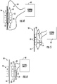
Figure 2 schematically illustrates an exampleelevator system device keypad 40 and adisplay screen 42. The passenger interface portion allows a passenger to provide an indication regarding desired elevator service or otherwise to communicate information to the elevator system. The passenger interface portion also allows for a passenger to receive information from the elevator system, such as an indication of how the elevator system will address the passenger's request for service. - The
device Figure 2 , includes asurface 44 adjacent the passenger interface portion. Thesurface 44 in this example provides an aesthetic surround adjacent the passenger interface portion. A magnetically actuatedswitch 50 is concealed behind thesurface 44 so that theswitch 50 is not visible to an elevator passenger or another individual looking at thedevice switch 50 is provided to authorized individuals who need to gain access to features or control over theelevator system 20 for service or maintenance, for example. - The
surface 44 in the illustrated example does not include any indication or characteristic that would suggest or indicate the presence of the magnetically actuatedswitch 50 behind thesurface 44. Concealing the magnetically actuatedswitch 50 in a manner that leaves its presence undetectable to an ordinary observer reduces a likelihood for any attempted vandalism or unauthorized access to restricted features of the elevator system. - In other embodiments, the
surface 44 or another portion of thedevice 30 includes an indication or characteristic that shows an authorized individual where theswitch 50 is behind thesurface 44. Such an indication may be informative to authorized individuals (e.g., elevator mechanics or maintenance personnel) without making the presence of theswitch 50 apparent to a typical elevator passenger. - The magnetically actuated
switch 50 allows an authorized individual to gain access to a variety of elevator system functions or features. For example, an authorized mechanic or technician may need to perform a power reset, a diagnostic procedure, or an update of thedevice elevator system 20 that can be accessed or controlled through an interaction with that device. Such an authorized individual has information or can obtain information regarding the location of the magnetically actuatedswitch 50 so that such an individual can gain the necessary access. -
Figure 3 schematically illustrates an example embodiment of a magnetically actuatedswitch 50. At least onemagnet 52 is associated with at least one switch contact. In this example, there aremultiple switch contacts Figure 3 . In this example, a biasingmember 60 biases thecontact 56 away from thecontacts 54 to keep the switch in an open state. In the example ofFigures 3 and4 , the biasingmember 60 comprises a hinge-style spring. - As shown in
Figure 4 , when an authorized individual places a magnetic key 70 in proximity to theswitch 50, themagnet 52 is attracted to or drawn toward themagnetic key 70. The magnetic attraction between themagnetic key 70 and themagnet 52 overcomes the bias of the biasingmember 60 to move the magnetically actuatedswitch 50 between the open state shown inFigure 3 and the closed state shown inFigure 4 . Such movement of themagnet 52 causes theswitch contact 56 to move into contact with theswitch contacts 54 to complete or close a circuit. In this example, when the magnetically actuatedswitch 50 is in a closed state, electrical energy can flow through theswitch 50 which provides an indication to acontrol circuit 62 that an authorized individual desires access to one or more features of the elevator system. The manner in which thecontrol circuit 62 provides such access to an authorized individual can occur in a known manner. -
Figure 5 schematically illustrates another example magnetically actuated switch configuration. In this example, the magnetically actuatedswitch 50 is in a normally open state but in this example, the presence of an appropriate magnetic key 70 causes movement of themagnet 52 away from thesurface 44 to cause thecontact 56 to move into conductive contact with thecontacts 54. In this example, when themagnetic key 70 is situated to repel themagnet 52, the magnetically actuatedswitch 50 moves from an open to a closed state. - In either of the example switch configurations, the
magnet 52 has a selected magnetic pattern, such as an arrangement of the magnet poles. The key 70 has to have a corresponding magnetic pattern to actuate theswitch 50. - While the examples of
Figures 3-6 include closing the magnetically actuatedswitch 50 to initiate authorized access to selected features of the elevator system, other switch configurations are in a normally closed state and opening the switch with an appropriate magnetic key initiates authorized access. - Having the magnetically actuated
switch 50 concealed behind thesurface 44 removes the presence of theswitch 50 from public view. Additionally, there is no requirement for any openings or visible switches or buttons that might otherwise be susceptible to vandalism. Embodiments designed according to this invention, therefore, provide enhanced security over elevator system devices and features while still providing relatively convenient access for an authorized individual. - The preceding description is exemplary rather than limiting in nature. Variations and modifications to the disclosed examples may become apparent to those skilled in the art that do not necessarily depart from the essence of this invention. The scope of legal protection given to this invention can only be determined by studying the following claims.
Claims (15)
- An elevator system device, comprising:an interface configured to operate in a first mode that allows an elevator passenger to communicate with the elevator system by at least one of inputting an indication for desired elevator service and receiving an indication regarding elevator service; anda magnetically actuated switch that selectively causes the interface to operate in a second mode that allows an authorized individual to communicate with the elevator system in a manner that is different than an elevator passenger communication in the first mode, the magnetically actuated switch including at least one magnet and at least one switch contact that changes between an open and closed state based on an interaction between the at least one magnet and a magnetic key brought into proximity of the at least one magnet by the authorized individual.
- The elevator system device of claim 1, comprising
a surface that is visible to the passenger or authorized individual,
and wherein the magnetically actuated switch is situated behind a portion of the surface that conceals the magnetically actuated switch from the passenger. - The elevator system device of claim 2, wherein
the surface has a visible characteristic on the portion of the surface that does not provide any indication of the magnetically actuated switch behind the surface. - The elevator system device of any preceding claim, wherein
the magnetically actuated switch includes a biasing member that biases the at least one switch contact into a selected one of the open or closed states and optionally wherein the biasing member comprises a spring or a hinge-style spring; and
the at least one magnet causes movement of the at least one switch contact into the other of the closed or open state by moving the at least one switch contact against the bias of the biasing member based on the interaction between the at least one magnet and the magnetic key. - The elevator system device of any preceding claim, wherein
the device comprises a controller that controls whether the interface operates in the first mode or the second mode; and
actuation of the magnetically actuated switch provides an indication to the controller to operate in the second mode to allow the authorized individual to communicate with the elevator system. - The elevator system device of any preceding claim, wherein
the at least one magnet has a selected magnetic pattern; and
the magnetic key has a corresponding magnetic pattern to activate the magnetically activated switch. - The elevator system device of any preceding claim, wherein
the at least one magnet is supported to move based on the interaction with the magnetic key; and
movement of the at least one magnet causes movement of the at least one switch contact between the open and closed states;
and optionally wherein at least one of magnetic attraction or magnetic repulsion between the at least one magnet and the magnetic key causes the movement of the at least one magnet. - The elevator system device of any preceding claim, wherein
the at least one switch contact is electrically conductive when the at least one switch contact is in the closed state;
the at least one switch contact is electrically conductive independent of a magnetic field of the at least one magnet; and
the at least one switch contact is electrically conductive independent of a magnetic field of the magnetic key. - The elevator system device of any preceding claim, comprising
a surface adjacent to the interface and whereinthe surface is visible to the passenger;the magnetically actuated switch is concealed from the passenger's view behind the surface; andthe device includes an indication of the magnetically actuated switch position behind the surface;and optionally wherein the surface has an indicator or a characteristic that indicates that the magnetically actuated switch is behind the surface. - A method of preventing unauthorized access to features of an elevator system device, the method comprising:situating a passenger interface portion of the device in a location where the passenger interface portion is accessible by an elevator passenger;situating a magnetically actuated switch near the passenger interface portion, the magnetically actuated switch controlling an ability to access preselected features of the elevator system; andconcealing the magnetically actuated switch such that the magnetically actuated switch is not visible to the elevator passenger.
- The method of claim 10, comprising concealing the magnetically actuated switch behind a surface adjacent the passenger interface portion.
- The method of claim 11, wherein the surface does not have any indicator or characteristic that would indicate that the magnetically actuated switch is behind the surface.
- The method of claim 11, wherein the device includes an indication or a characteristic that indicates a position of the magnetically actuated switch behind the surface, and preferably wherein the indication or characteristic is on the surface.
- The method of any of claims 10-13, comprising
requiring a magnetic key to be placed in close proximity to the magnetically actuated switch to actuate the switch. - The method of claim 14, wherein
the magnetically actuated switch includes at least one magnet and at least one switch contact;
the at least one magnet moves based on magnetic interaction between the at least one magnet and the magnetic key; and
movement of the at least one magnet moves the at least one switch contact between an open and a closed state.
Applications Claiming Priority (1)
| Application Number | Priority Date | Filing Date | Title |
|---|---|---|---|
| US15/593,775 US10414628B2 (en) | 2017-05-12 | 2017-05-12 | Elevator system device with authorized access control |
Publications (2)
| Publication Number | Publication Date |
|---|---|
| EP3415455A1 true EP3415455A1 (en) | 2018-12-19 |
| EP3415455B1 EP3415455B1 (en) | 2020-02-26 |
Family
ID=62152495
Family Applications (1)
| Application Number | Title | Priority Date | Filing Date |
|---|---|---|---|
| EP18171941.0A Active EP3415455B1 (en) | 2017-05-12 | 2018-05-11 | Elevator system device with authorized access control |
Country Status (5)
| Country | Link |
|---|---|
| US (1) | US10414628B2 (en) |
| EP (1) | EP3415455B1 (en) |
| KR (1) | KR102073237B1 (en) |
| CN (1) | CN108861915B (en) |
| ES (1) | ES2785984T3 (en) |
Families Citing this family (5)
| Publication number | Priority date | Publication date | Assignee | Title |
|---|---|---|---|---|
| EP3319897B1 (en) * | 2015-07-10 | 2021-08-25 | Otis Elevator Company | Landing door lock failsafe protection device |
| US10414628B2 (en) * | 2017-05-12 | 2019-09-17 | Otis Elevator Company | Elevator system device with authorized access control |
| USD883125S1 (en) | 2017-06-23 | 2020-05-05 | Mitsubishi Electric Corporation | Frame with elevator indicator |
| CN114867676B (en) * | 2019-12-17 | 2024-12-13 | 因温特奥股份公司 | Method of operating an elevator for inspection |
| USD1056747S1 (en) * | 2021-12-30 | 2025-01-07 | Inventio Ag | Elevator operating/indicating panel |
Citations (4)
| Publication number | Priority date | Publication date | Assignee | Title |
|---|---|---|---|---|
| JPH0326676A (en) * | 1989-06-26 | 1991-02-05 | Hitachi Elevator Eng & Service Co Ltd | Operation control panel for elevator |
| US20090133969A1 (en) * | 2004-11-30 | 2009-05-28 | Vlad Zaharia | Destination entry passenger interface with multiple functions |
| US20120031708A1 (en) * | 2010-08-04 | 2012-02-09 | Marco Aluisetti | Magnetic lock for a control unit in an elevator installation |
| EP2955144A1 (en) * | 2014-06-13 | 2015-12-16 | Kone Corporation | Control panel for an elevator |
Family Cites Families (37)
| Publication number | Priority date | Publication date | Assignee | Title |
|---|---|---|---|---|
| DE1553358B2 (en) * | 1965-07-31 | 1970-07-16 | Huwil-Werke Hugo Willach & Söhne, 5224 Ruppichteroth | Rotary cylinder lock with solenoid operated tumblers |
| US3813624A (en) | 1973-04-09 | 1974-05-28 | R Deitch | Magnetic lock switch |
| CA1328474C (en) * | 1985-11-07 | 1994-04-12 | Roger Conington Richards | Magnetically operated latch |
| DE3876079D1 (en) | 1987-12-18 | 1992-12-24 | Inventio Ag | CALL REGISTER AND INDICATOR DEVICES ON THE FLOOR PLANTS. |
| US4848812A (en) * | 1988-04-08 | 1989-07-18 | Slaughter Steven J | Concealed safety lock |
| JPH02115481A (en) * | 1988-09-28 | 1990-04-27 | Juan Capdevila | Key controlling access and related magnetic lock |
| JPH0780651B2 (en) * | 1989-06-23 | 1995-08-30 | 株式会社日立製作所 | Elevator power supply |
| JP2526317B2 (en) * | 1991-01-25 | 1996-08-21 | 日本電子ロック株式会社 | Magnetic card lock |
| US5283546A (en) | 1991-05-13 | 1994-02-01 | Motorola, Inc. | Vandal-resistant call box |
| US5485733A (en) * | 1993-05-13 | 1996-01-23 | Hoffman; Charles G. | Concealed magnetic lock for cabinet closure |
| US5668533A (en) | 1995-06-07 | 1997-09-16 | Securitron Magnalock Corporation | High security balanced-type, magnetically-actuated proximity switch system |
| US6227335B1 (en) * | 1999-12-10 | 2001-05-08 | Invento Ag | Elevator car operating panel |
| AU757159C (en) * | 2000-05-16 | 2003-07-03 | Mu Hua Investments Limited | Biometric key |
| JP2003201071A (en) * | 2001-11-01 | 2003-07-15 | Inventio Ag | System for transporting or access controlling person or article, maintaining method and device for the same, computer program product and method of reforming building using the system |
| CN2553497Y (en) * | 2002-06-18 | 2003-05-28 | 西安信源高压电器有限公司 | Electromagnetic lock and key with power supply |
| BR0212037A (en) * | 2002-06-19 | 2004-08-17 | Arvinmeritor Light Vehicle Sys | Actuators, coupling arrangement, valves and relay for vehicle use |
| US7059159B2 (en) * | 2003-02-06 | 2006-06-13 | Mi-Jack Products, Inc. | Security system for cargo trailers |
| PE20040794A1 (en) | 2003-03-05 | 2004-12-22 | Inventio Ag | PREVENTION OF UNAUTHORIZED ACCESS TO LIFT BOXES |
| SG139660A1 (en) | 2006-07-26 | 2008-02-29 | Inventio Ag | Method of controlling access to an elevator car |
| EP2072450A1 (en) | 2007-12-21 | 2009-06-24 | Inventio Ag | Circuit for resetting an elevator safety chain |
| WO2009117343A1 (en) * | 2008-03-20 | 2009-09-24 | Rotary Lift, A Division Of Dover Industrial Products, Inc. | Lift control interface |
| WO2011076531A1 (en) * | 2009-12-21 | 2011-06-30 | Inventio Ag | Shaft access enabling device of an elevator system |
| DE102011054590B4 (en) * | 2011-10-18 | 2022-06-09 | Elgo-Electronic Gmbh & Co. Kg | Device for detecting the position of an elevator car and method for operating an elevator system |
| EP3060509B1 (en) * | 2013-10-23 | 2020-12-16 | Inventio AG | Safety system for a lift, lift system and method for operating such a safety system |
| US9340342B2 (en) | 2014-07-28 | 2016-05-17 | Energizer Brands, Llc | Product packaging having magnetic activated test mode |
| CN107000973B (en) * | 2014-10-02 | 2020-10-13 | 通力股份公司 | Wireless Communication in Elevators |
| WO2016079772A1 (en) * | 2014-11-21 | 2016-05-26 | 三菱電機株式会社 | Elevator device |
| CN104481223B (en) * | 2014-12-05 | 2017-04-19 | 深圳市创荣发电子有限公司 | Code programmed lock and magnetic-control locking and unlocking method |
| CN104576190B (en) | 2015-01-27 | 2017-01-18 | 象山松本磁性开关厂 | Multifunctional bi-stable magnet switch for elevator |
| CN108367888B (en) * | 2015-12-17 | 2020-03-03 | 因温特奥股份公司 | Personnel transport equipment, maintenance method, and maintenance controller |
| CN205577646U (en) * | 2016-02-19 | 2016-09-14 | 陈义胜 | Serial -type electromagnetic lock |
| DE112016006793T5 (en) * | 2016-04-26 | 2019-01-17 | Mitsubishi Electric Corporation | LIFT OPERATION INSPECTION DEVICE |
| US10547917B2 (en) * | 2017-05-12 | 2020-01-28 | Otis Elevator Company | Ride quality mobile terminal device application |
| US10414628B2 (en) * | 2017-05-12 | 2019-09-17 | Otis Elevator Company | Elevator system device with authorized access control |
| DK3403971T3 (en) * | 2017-05-19 | 2021-01-25 | Kone Corp | PROCEDURE FOR PERFORMING A MANUAL DRIVE IN AN ELEVATOR AFTER POWER DISCONNECTION |
| CN109110593B (en) * | 2017-06-22 | 2022-04-26 | 奥的斯电梯公司 | Communication system and communication method for elevator system |
| US10589960B2 (en) * | 2017-07-31 | 2020-03-17 | Otis Elevator Company | User device including secondary-touch elevator service request interface |
-
2017
- 2017-05-12 US US15/593,775 patent/US10414628B2/en active Active
-
2018
- 2018-05-09 KR KR1020180052958A patent/KR102073237B1/en not_active Expired - Fee Related
- 2018-05-11 EP EP18171941.0A patent/EP3415455B1/en active Active
- 2018-05-11 ES ES18171941T patent/ES2785984T3/en active Active
- 2018-05-11 CN CN201810450351.0A patent/CN108861915B/en not_active Expired - Fee Related
Patent Citations (4)
| Publication number | Priority date | Publication date | Assignee | Title |
|---|---|---|---|---|
| JPH0326676A (en) * | 1989-06-26 | 1991-02-05 | Hitachi Elevator Eng & Service Co Ltd | Operation control panel for elevator |
| US20090133969A1 (en) * | 2004-11-30 | 2009-05-28 | Vlad Zaharia | Destination entry passenger interface with multiple functions |
| US20120031708A1 (en) * | 2010-08-04 | 2012-02-09 | Marco Aluisetti | Magnetic lock for a control unit in an elevator installation |
| EP2955144A1 (en) * | 2014-06-13 | 2015-12-16 | Kone Corporation | Control panel for an elevator |
Also Published As
| Publication number | Publication date |
|---|---|
| US10414628B2 (en) | 2019-09-17 |
| US20180327216A1 (en) | 2018-11-15 |
| ES2785984T3 (en) | 2020-10-08 |
| CN108861915B (en) | 2023-09-12 |
| KR102073237B1 (en) | 2020-03-02 |
| EP3415455B1 (en) | 2020-02-26 |
| KR20180124749A (en) | 2018-11-21 |
| CN108861915A (en) | 2018-11-23 |
Similar Documents
| Publication | Publication Date | Title |
|---|---|---|
| EP3415455B1 (en) | Elevator system device with authorized access control | |
| KR101374988B1 (en) | Method of controlling access to an elevator car | |
| US10549951B2 (en) | Unlocking device, elevator system having an unlocking device, and method for actuating an unlocking device | |
| SG187692A1 (en) | Magnetic lock for an operating unit in an elevator system | |
| CA2459447A1 (en) | Preventing unauthorized hoistway access | |
| AU2021260096B2 (en) | Elevator operating device having two call input devices disposed separate from each other with respect to passengers | |
| US7562748B2 (en) | Elevator call button with tactile feedback | |
| CN110255312B (en) | Elevator car operating panel | |
| CN108861916B (en) | Car operating panel for an elevator car with at least two car doors | |
| US4471856A (en) | Elevator door interlock | |
| JP6317883B2 (en) | Call button press restriction device | |
| JP5981586B1 (en) | Elevator system | |
| US7063189B2 (en) | Method and apparatus for a scanning an elevator entry way | |
| JP2006256830A (en) | Elevator system | |
| WO2001044094A1 (en) | Flashing 'door open' button for an elevator car | |
| CN107531447A (en) | The sedan operation panel of elevator device | |
| CN115135593A (en) | Notification device and method for elevator operation mode | |
| HK1236497A1 (en) | Unlocking device, elevator system having an unlocking device, and method for actuating an unlocking device | |
| KR101031533B1 (en) | Switchgear for elevator control | |
| JP2002003098A (en) | Elevator with non-stop switch | |
| HK40064156B (en) | Touch-sensitive lift operation device for direction of travel calls | |
| JP2006298533A (en) | Elevator car operation panel | |
| CN117897350A (en) | Mobile device and method for monitoring elevator equipment | |
| KR20090043659A (en) | Touch key switch | |
| HK1233238A1 (en) | Elevator system |
Legal Events
| Date | Code | Title | Description |
|---|---|---|---|
| PUAI | Public reference made under article 153(3) epc to a published international application that has entered the european phase |
Free format text: ORIGINAL CODE: 0009012 |
|
| STAA | Information on the status of an ep patent application or granted ep patent |
Free format text: STATUS: THE APPLICATION HAS BEEN PUBLISHED |
|
| AK | Designated contracting states |
Kind code of ref document: A1 Designated state(s): AL AT BE BG CH CY CZ DE DK EE ES FI FR GB GR HR HU IE IS IT LI LT LU LV MC MK MT NL NO PL PT RO RS SE SI SK SM TR |
|
| AX | Request for extension of the european patent |
Extension state: BA ME |
|
| STAA | Information on the status of an ep patent application or granted ep patent |
Free format text: STATUS: REQUEST FOR EXAMINATION WAS MADE |
|
| 17P | Request for examination filed |
Effective date: 20190618 |
|
| RBV | Designated contracting states (corrected) |
Designated state(s): AL AT BE BG CH CY CZ DE DK EE ES FI FR GB GR HR HU IE IS IT LI LT LU LV MC MK MT NL NO PL PT RO RS SE SI SK SM TR |
|
| GRAP | Despatch of communication of intention to grant a patent |
Free format text: ORIGINAL CODE: EPIDOSNIGR1 |
|
| STAA | Information on the status of an ep patent application or granted ep patent |
Free format text: STATUS: GRANT OF PATENT IS INTENDED |
|
| INTG | Intention to grant announced |
Effective date: 20190910 |
|
| GRAS | Grant fee paid |
Free format text: ORIGINAL CODE: EPIDOSNIGR3 |
|
| GRAA | (expected) grant |
Free format text: ORIGINAL CODE: 0009210 |
|
| STAA | Information on the status of an ep patent application or granted ep patent |
Free format text: STATUS: THE PATENT HAS BEEN GRANTED |
|
| AK | Designated contracting states |
Kind code of ref document: B1 Designated state(s): AL AT BE BG CH CY CZ DE DK EE ES FI FR GB GR HR HU IE IS IT LI LT LU LV MC MK MT NL NO PL PT RO RS SE SI SK SM TR |
|
| REG | Reference to a national code |
Ref country code: GB Ref legal event code: FG4D |
|
| REG | Reference to a national code |
Ref country code: CH Ref legal event code: EP |
|
| REG | Reference to a national code |
Ref country code: DE Ref legal event code: R096 Ref document number: 602018002633 Country of ref document: DE |
|
| REG | Reference to a national code |
Ref country code: AT Ref legal event code: REF Ref document number: 1237394 Country of ref document: AT Kind code of ref document: T Effective date: 20200315 |
|
| REG | Reference to a national code |
Ref country code: IE Ref legal event code: FG4D |
|
| PG25 | Lapsed in a contracting state [announced via postgrant information from national office to epo] |
Ref country code: RS Free format text: LAPSE BECAUSE OF FAILURE TO SUBMIT A TRANSLATION OF THE DESCRIPTION OR TO PAY THE FEE WITHIN THE PRESCRIBED TIME-LIMIT Effective date: 20200226 Ref country code: FI Free format text: LAPSE BECAUSE OF FAILURE TO SUBMIT A TRANSLATION OF THE DESCRIPTION OR TO PAY THE FEE WITHIN THE PRESCRIBED TIME-LIMIT Effective date: 20200226 Ref country code: NO Free format text: LAPSE BECAUSE OF FAILURE TO SUBMIT A TRANSLATION OF THE DESCRIPTION OR TO PAY THE FEE WITHIN THE PRESCRIBED TIME-LIMIT Effective date: 20200526 |
|
| REG | Reference to a national code |
Ref country code: NL Ref legal event code: MP Effective date: 20200226 |
|
| REG | Reference to a national code |
Ref country code: LT Ref legal event code: MG4D |
|
| PG25 | Lapsed in a contracting state [announced via postgrant information from national office to epo] |
Ref country code: LV Free format text: LAPSE BECAUSE OF FAILURE TO SUBMIT A TRANSLATION OF THE DESCRIPTION OR TO PAY THE FEE WITHIN THE PRESCRIBED TIME-LIMIT Effective date: 20200226 Ref country code: SE Free format text: LAPSE BECAUSE OF FAILURE TO SUBMIT A TRANSLATION OF THE DESCRIPTION OR TO PAY THE FEE WITHIN THE PRESCRIBED TIME-LIMIT Effective date: 20200226 Ref country code: BG Free format text: LAPSE BECAUSE OF FAILURE TO SUBMIT A TRANSLATION OF THE DESCRIPTION OR TO PAY THE FEE WITHIN THE PRESCRIBED TIME-LIMIT Effective date: 20200526 Ref country code: IS Free format text: LAPSE BECAUSE OF FAILURE TO SUBMIT A TRANSLATION OF THE DESCRIPTION OR TO PAY THE FEE WITHIN THE PRESCRIBED TIME-LIMIT Effective date: 20200626 Ref country code: GR Free format text: LAPSE BECAUSE OF FAILURE TO SUBMIT A TRANSLATION OF THE DESCRIPTION OR TO PAY THE FEE WITHIN THE PRESCRIBED TIME-LIMIT Effective date: 20200527 Ref country code: HR Free format text: LAPSE BECAUSE OF FAILURE TO SUBMIT A TRANSLATION OF THE DESCRIPTION OR TO PAY THE FEE WITHIN THE PRESCRIBED TIME-LIMIT Effective date: 20200226 |
|
| PG25 | Lapsed in a contracting state [announced via postgrant information from national office to epo] |
Ref country code: NL Free format text: LAPSE BECAUSE OF FAILURE TO SUBMIT A TRANSLATION OF THE DESCRIPTION OR TO PAY THE FEE WITHIN THE PRESCRIBED TIME-LIMIT Effective date: 20200226 |
|
| REG | Reference to a national code |
Ref country code: ES Ref legal event code: FG2A Ref document number: 2785984 Country of ref document: ES Kind code of ref document: T3 Effective date: 20201008 |
|
| PG25 | Lapsed in a contracting state [announced via postgrant information from national office to epo] |
Ref country code: SK Free format text: LAPSE BECAUSE OF FAILURE TO SUBMIT A TRANSLATION OF THE DESCRIPTION OR TO PAY THE FEE WITHIN THE PRESCRIBED TIME-LIMIT Effective date: 20200226 Ref country code: SM Free format text: LAPSE BECAUSE OF FAILURE TO SUBMIT A TRANSLATION OF THE DESCRIPTION OR TO PAY THE FEE WITHIN THE PRESCRIBED TIME-LIMIT Effective date: 20200226 Ref country code: EE Free format text: LAPSE BECAUSE OF FAILURE TO SUBMIT A TRANSLATION OF THE DESCRIPTION OR TO PAY THE FEE WITHIN THE PRESCRIBED TIME-LIMIT Effective date: 20200226 Ref country code: DK Free format text: LAPSE BECAUSE OF FAILURE TO SUBMIT A TRANSLATION OF THE DESCRIPTION OR TO PAY THE FEE WITHIN THE PRESCRIBED TIME-LIMIT Effective date: 20200226 Ref country code: CZ Free format text: LAPSE BECAUSE OF FAILURE TO SUBMIT A TRANSLATION OF THE DESCRIPTION OR TO PAY THE FEE WITHIN THE PRESCRIBED TIME-LIMIT Effective date: 20200226 Ref country code: RO Free format text: LAPSE BECAUSE OF FAILURE TO SUBMIT A TRANSLATION OF THE DESCRIPTION OR TO PAY THE FEE WITHIN THE PRESCRIBED TIME-LIMIT Effective date: 20200226 Ref country code: PT Free format text: LAPSE BECAUSE OF FAILURE TO SUBMIT A TRANSLATION OF THE DESCRIPTION OR TO PAY THE FEE WITHIN THE PRESCRIBED TIME-LIMIT Effective date: 20200719 Ref country code: LT Free format text: LAPSE BECAUSE OF FAILURE TO SUBMIT A TRANSLATION OF THE DESCRIPTION OR TO PAY THE FEE WITHIN THE PRESCRIBED TIME-LIMIT Effective date: 20200226 |
|
| REG | Reference to a national code |
Ref country code: AT Ref legal event code: MK05 Ref document number: 1237394 Country of ref document: AT Kind code of ref document: T Effective date: 20200226 |
|
| REG | Reference to a national code |
Ref country code: DE Ref legal event code: R097 Ref document number: 602018002633 Country of ref document: DE |
|
| PLBE | No opposition filed within time limit |
Free format text: ORIGINAL CODE: 0009261 |
|
| STAA | Information on the status of an ep patent application or granted ep patent |
Free format text: STATUS: NO OPPOSITION FILED WITHIN TIME LIMIT |
|
| PG25 | Lapsed in a contracting state [announced via postgrant information from national office to epo] |
Ref country code: MC Free format text: LAPSE BECAUSE OF FAILURE TO SUBMIT A TRANSLATION OF THE DESCRIPTION OR TO PAY THE FEE WITHIN THE PRESCRIBED TIME-LIMIT Effective date: 20200226 Ref country code: AT Free format text: LAPSE BECAUSE OF FAILURE TO SUBMIT A TRANSLATION OF THE DESCRIPTION OR TO PAY THE FEE WITHIN THE PRESCRIBED TIME-LIMIT Effective date: 20200226 Ref country code: IT Free format text: LAPSE BECAUSE OF FAILURE TO SUBMIT A TRANSLATION OF THE DESCRIPTION OR TO PAY THE FEE WITHIN THE PRESCRIBED TIME-LIMIT Effective date: 20200226 |
|
| 26N | No opposition filed |
Effective date: 20201127 |
|
| PG25 | Lapsed in a contracting state [announced via postgrant information from national office to epo] |
Ref country code: SI Free format text: LAPSE BECAUSE OF FAILURE TO SUBMIT A TRANSLATION OF THE DESCRIPTION OR TO PAY THE FEE WITHIN THE PRESCRIBED TIME-LIMIT Effective date: 20200226 Ref country code: PL Free format text: LAPSE BECAUSE OF FAILURE TO SUBMIT A TRANSLATION OF THE DESCRIPTION OR TO PAY THE FEE WITHIN THE PRESCRIBED TIME-LIMIT Effective date: 20200226 |
|
| REG | Reference to a national code |
Ref country code: BE Ref legal event code: MM Effective date: 20200531 |
|
| PG25 | Lapsed in a contracting state [announced via postgrant information from national office to epo] |
Ref country code: LU Free format text: LAPSE BECAUSE OF NON-PAYMENT OF DUE FEES Effective date: 20200511 |
|
| PG25 | Lapsed in a contracting state [announced via postgrant information from national office to epo] |
Ref country code: IE Free format text: LAPSE BECAUSE OF NON-PAYMENT OF DUE FEES Effective date: 20200511 |
|
| PG25 | Lapsed in a contracting state [announced via postgrant information from national office to epo] |
Ref country code: BE Free format text: LAPSE BECAUSE OF NON-PAYMENT OF DUE FEES Effective date: 20200531 |
|
| REG | Reference to a national code |
Ref country code: CH Ref legal event code: PL |
|
| PG25 | Lapsed in a contracting state [announced via postgrant information from national office to epo] |
Ref country code: CH Free format text: LAPSE BECAUSE OF NON-PAYMENT OF DUE FEES Effective date: 20210531 Ref country code: LI Free format text: LAPSE BECAUSE OF NON-PAYMENT OF DUE FEES Effective date: 20210531 |
|
| PG25 | Lapsed in a contracting state [announced via postgrant information from national office to epo] |
Ref country code: TR Free format text: LAPSE BECAUSE OF FAILURE TO SUBMIT A TRANSLATION OF THE DESCRIPTION OR TO PAY THE FEE WITHIN THE PRESCRIBED TIME-LIMIT Effective date: 20200226 Ref country code: MT Free format text: LAPSE BECAUSE OF FAILURE TO SUBMIT A TRANSLATION OF THE DESCRIPTION OR TO PAY THE FEE WITHIN THE PRESCRIBED TIME-LIMIT Effective date: 20200226 Ref country code: CY Free format text: LAPSE BECAUSE OF FAILURE TO SUBMIT A TRANSLATION OF THE DESCRIPTION OR TO PAY THE FEE WITHIN THE PRESCRIBED TIME-LIMIT Effective date: 20200226 |
|
| PG25 | Lapsed in a contracting state [announced via postgrant information from national office to epo] |
Ref country code: MK Free format text: LAPSE BECAUSE OF FAILURE TO SUBMIT A TRANSLATION OF THE DESCRIPTION OR TO PAY THE FEE WITHIN THE PRESCRIBED TIME-LIMIT Effective date: 20200226 Ref country code: AL Free format text: LAPSE BECAUSE OF FAILURE TO SUBMIT A TRANSLATION OF THE DESCRIPTION OR TO PAY THE FEE WITHIN THE PRESCRIBED TIME-LIMIT Effective date: 20200226 |
|
| GBPC | Gb: european patent ceased through non-payment of renewal fee |
Effective date: 20220511 |
|
| PG25 | Lapsed in a contracting state [announced via postgrant information from national office to epo] |
Ref country code: GB Free format text: LAPSE BECAUSE OF NON-PAYMENT OF DUE FEES Effective date: 20220511 |
|
| PGFP | Annual fee paid to national office [announced via postgrant information from national office to epo] |
Ref country code: DE Payment date: 20240418 Year of fee payment: 7 |
|
| PGFP | Annual fee paid to national office [announced via postgrant information from national office to epo] |
Ref country code: ES Payment date: 20240603 Year of fee payment: 7 |
|
| PGFP | Annual fee paid to national office [announced via postgrant information from national office to epo] |
Ref country code: FR Payment date: 20240418 Year of fee payment: 7 |
|
| REG | Reference to a national code |
Ref country code: DE Ref legal event code: R119 Ref document number: 602018002633 Country of ref document: DE |
|
| PG25 | Lapsed in a contracting state [announced via postgrant information from national office to epo] |
Ref country code: DE Free format text: LAPSE BECAUSE OF NON-PAYMENT OF DUE FEES Effective date: 20251202 |
|
| PG25 | Lapsed in a contracting state [announced via postgrant information from national office to epo] |
Ref country code: FR Free format text: LAPSE BECAUSE OF NON-PAYMENT OF DUE FEES Effective date: 20250531 |