EP3415422A1 - Method and apparatus to improve lift to drag ratio of a rotor blade - Google Patents
Method and apparatus to improve lift to drag ratio of a rotor blade Download PDFInfo
- Publication number
- EP3415422A1 EP3415422A1 EP18157738.8A EP18157738A EP3415422A1 EP 3415422 A1 EP3415422 A1 EP 3415422A1 EP 18157738 A EP18157738 A EP 18157738A EP 3415422 A1 EP3415422 A1 EP 3415422A1
- Authority
- EP
- European Patent Office
- Prior art keywords
- leading edge
- extension member
- edge extension
- rotor blade
- blade
- Prior art date
- Legal status (The legal status is an assumption and is not a legal conclusion. Google has not performed a legal analysis and makes no representation as to the accuracy of the status listed.)
- Granted
Links
Images




Classifications
-
- B—PERFORMING OPERATIONS; TRANSPORTING
- B64—AIRCRAFT; AVIATION; COSMONAUTICS
- B64C—AEROPLANES; HELICOPTERS
- B64C11/00—Propellers, e.g. of ducted type; Features common to propellers and rotors for rotorcraft
- B64C11/16—Blades
- B64C11/18—Aerodynamic features
-
- B—PERFORMING OPERATIONS; TRANSPORTING
- B64—AIRCRAFT; AVIATION; COSMONAUTICS
- B64C—AEROPLANES; HELICOPTERS
- B64C11/00—Propellers, e.g. of ducted type; Features common to propellers and rotors for rotorcraft
- B64C11/16—Blades
- B64C11/20—Constructional features
- B64C11/24—Hollow blades
-
- B—PERFORMING OPERATIONS; TRANSPORTING
- B64—AIRCRAFT; AVIATION; COSMONAUTICS
- B64C—AEROPLANES; HELICOPTERS
- B64C27/00—Rotorcraft; Rotors peculiar thereto
- B64C27/32—Rotors
- B64C27/46—Blades
- B64C27/473—Constructional features
-
- F—MECHANICAL ENGINEERING; LIGHTING; HEATING; WEAPONS; BLASTING
- F03—MACHINES OR ENGINES FOR LIQUIDS; WIND, SPRING, OR WEIGHT MOTORS; PRODUCING MECHANICAL POWER OR A REACTIVE PROPULSIVE THRUST, NOT OTHERWISE PROVIDED FOR
- F03D—WIND MOTORS
- F03D1/00—Wind motors with rotation axis substantially parallel to the air flow entering the rotor
- F03D1/06—Rotors
- F03D1/065—Rotors characterised by their construction elements
- F03D1/0675—Rotors characterised by their construction elements of the blades
-
- B—PERFORMING OPERATIONS; TRANSPORTING
- B64—AIRCRAFT; AVIATION; COSMONAUTICS
- B64C—AEROPLANES; HELICOPTERS
- B64C29/00—Aircraft capable of landing or taking-off vertically, e.g. vertical take-off and landing [VTOL] aircraft
- B64C29/0008—Aircraft capable of landing or taking-off vertically, e.g. vertical take-off and landing [VTOL] aircraft having its flight directional axis horizontal when grounded
- B64C29/0016—Aircraft capable of landing or taking-off vertically, e.g. vertical take-off and landing [VTOL] aircraft having its flight directional axis horizontal when grounded the lift during taking-off being created by free or ducted propellers or by blowers
- B64C29/0033—Aircraft capable of landing or taking-off vertically, e.g. vertical take-off and landing [VTOL] aircraft having its flight directional axis horizontal when grounded the lift during taking-off being created by free or ducted propellers or by blowers the propellers being tiltable relative to the fuselage
-
- Y—GENERAL TAGGING OF NEW TECHNOLOGICAL DEVELOPMENTS; GENERAL TAGGING OF CROSS-SECTIONAL TECHNOLOGIES SPANNING OVER SEVERAL SECTIONS OF THE IPC; TECHNICAL SUBJECTS COVERED BY FORMER USPC CROSS-REFERENCE ART COLLECTIONS [XRACs] AND DIGESTS
- Y02—TECHNOLOGIES OR APPLICATIONS FOR MITIGATION OR ADAPTATION AGAINST CLIMATE CHANGE
- Y02E—REDUCTION OF GREENHOUSE GAS [GHG] EMISSIONS, RELATED TO ENERGY GENERATION, TRANSMISSION OR DISTRIBUTION
- Y02E10/00—Energy generation through renewable energy sources
- Y02E10/70—Wind energy
- Y02E10/72—Wind turbines with rotation axis in wind direction
Definitions
- the present disclosure relates to aircrafts and, more particularly, to aircraft rotor blades.
- the root portion of a rotor blade for a vertical take-off and landing (VTOL) aircraft experiences a wide range of aerodynamic conditions from hover (low relative velocity, high angle of attack) to cruise (high relative velocity, zero angle of attack).
- the conventional profile of the root portion of the rotor blade is typically thicker than the tip portion to accommodate hub attachment, bearings, and clearance through a large feathering motion range.
- the profile of the root portion of the rotor blade with a large thickness t to chord C ratio, see FIG. 4A cannot efficiently handle the wide range of operating conditions that the blade experiences due to early chordwise separation and subsequent rise in profile drag.
- VTOL aircraft namely the V-22 Osprey
- a removable fairing positioned over the blade grip to improve the aerodynamics of the aircraft during operation.
- the removable fairing is associated with movable portions or is removed to not interfere with the folding of the rotor blades during stowage of the aircraft.
- a removable fairing on or associated with a rotor blade is undesirable as the removable fairing can add weight to the blade and decrease efficiency during operation of the aircraft.
- a method for improving a lift to drag ratio of a rotor blade including providing a blade member having a leading edge and a trailing edge; providing a leading edge extension member; and coupling the leading edge extension member to a portion of the leading edge of the blade member to form the rotor blade.
- the blade member includes a root portion and a tip portion, the leading edge extension member is disposed on the root portion.
- the lift to drag ratio of the root portion of the rotor blade is determined by selectively tailoring at least one of a chord length, a thickness, and a shape of the leading edge extension member.
- leading edge extension member includes an inner surface that defines a hollow interior portion for receiving the blade member.
- the step of coupling includes coupling the blade member to at least a portion of the inner surface of the leading edge extension member.
- the blade member has an airfoil geometry including at least one of the following: a NACA geometry, a modified NACA geometry, and combinations thereof.
- leading edge extension member has a root end
- steps further include coupling an end closeout to the root end of the leading edge extension member.
- the method further includes locating the leading edge extension member on the blade member using a groove in the leading edge extension member.
- a rotor blade including a blade member having a leading edge, and a trailing edge; and a leading edge extension member disposed on the leading edge of the blade member, wherein the leading edge extension member is configured to extend the chord length of at least a portion of the rotor blade.
- the blade member includes a root portion and a tip portion, the leading edge extension member is disposed on the root portion of the blade member.
- chord length of the root portion of the blade member is more than the tip portion of the blade member.
- the blade member has an airfoil geometry including at least one of the following: a NACA geometry, a modified NACA geometry, and combinations thereof.
- the leading edge extension member includes a top side; a bottom side; and a curved portion disposed between the top side and bottom side; wherein the top side, bottom side, and the curved portion form a convex outer surface configured to extend at least a portion of the chord length of the rotor blade.
- the ramped portion has an inclined angle greater than an inclined angle of the upper portion.
- leading edge extension member further includes a groove disposed on at least one of the top side and the bottom side configured for locating the leading edge extension member on the blade member.
- leading edge extension member further includes an inner surface that defines a hollow interior portion for receiving the blade member.
- the rotor blade further includes an end closeout disposed on a root end of the leading edge extension member.
- a leading edge extension member for a rotor blade including a convex exterior surface configured to extend at least a portion of the chord length of the rotor blade.
- the convex exterior surface includes a ramped portion and an upper portion.
- the ramped portion has an inclined angle greater than an inclined angle of the upper portion.
- the convex exterior surface includes a top side, a bottom side, and a curved portion disposed between the top side and the bottom side.
- leading edge extension member further includes a groove disposed on at least one of the top side and the bottom side.
- leading edge extension member further includes a hollow interior portion configured to receive a blade member.
- a method for designing a rotor blade for generating improved lift and reduced drag as compared to a conventional rotor blade including increasing the chord length of the root portion of the rotor blade by disposing a leading edge extension member on the leading edge of a blade member.
- a leading edge extension member having a hollow interior portion to a leading edge of a blade member.
- a method of improving the lift to drag ratio of a rotor blade including providing a blade member having a root portion, a tip portion, a leading edge, and a trailing edge, providing a leading edge extension member having a hollow interior portion for receiving the blade member; selectively tailoring the leading edge extension member to determine the lift to drag ratio of a rotor blade; coupling the leading edge extension member to the root portion of the blade member to form the rotor blade.
- a method of manufacturing including contacting plies to a mold selectively configured to achieve the desired shape of the leading edge extension member; compacting the plies to form a pre-cured leading edge extension member; providing a blade member having a top surface and a bottom surface; providing a pre-cured leading edge extension member having an upper and lower inner surface defining a hollow interior portion for receiving the blade member; adhesively coupling the upper and lower inner surfaces of the leading edge extension member to the top and bottom surfaces of the blade member; coupling an end closeout to the root end of the leading edge extension member; and curing at least one of the leading edge extension member, the end closeout, and the blade member.
- FIGS. 1-2 depict aircraft 10 as a tiltrotor aircraft.
- FIGS. 1-2 depict three mutually orthogonal directions X, Y, and Z forming a three-dimensional frame of reference XYZ.
- Longitudinal axis X 14 corresponds to the roll axis that extends through the center of aircraft 10 in the fore and after directions.
- Transverse axis Y 18 is perpendicular to longitudinal axis 14 and corresponds to the pitch axis (also known as a control pitch axis or "CPA").
- the X-Y plane is considered to be "horizontal.”
- Vertical axis Z 22 is the yaw axis and is oriented perpendicularly with respect to the X-Y plane.
- the X-Z plane and Y-Z plane are considered to be "vertical.”
- Aircraft 10 includes fuselage 26 as a central main body. Fuselage 26 extends parallel to longitudinal axis 14 from a fuselage front end 30 to a fuselage rear end 34. Aircraft 10 further includes tail member 38 extending from fuselage rear end 34 of fuselage 26. Aircraft 10 includes wing 42 and wing 46 extending from fuselage 26 substantially parallel to transverse axis Y 18. Wing 42 is coupled to propulsion system 50, and wing 46 is coupled to propulsion system 54.
- Propulsion system 50 includes rotor assembly 58, and propulsion system 54 includes rotor assembly 62.
- Rotor assembly 58 includes rotor hub 66 and plurality of rotor blades 70 extending from rotor hub 66 and configured to rotate about axis 72.
- rotor assembly 62 includes rotor hub 74 and plurality of rotor blades 78 extending from rotor hub 74 and configured to rotate about axis 80.
- Each of rotor assemblies 58 and 62 can, for example, be coupled to and controlled with an engine and gearbox connected to a driveshaft, such as one continuous driveshaft extending from propulsion system 50 to propulsion system 54 or a segmented driveshaft separated by a gearbox.
- Rotor assemblies 58 and 62 are controllable and positionable to, for example, enable control of direction, thrust, and lift of aircraft 10.
- FIG. 1 illustrates aircraft 10 in a first configuration, in which propulsion systems 50 and 54 are positioned to provide a lifting thrust to aircraft 10, if activated.
- propulsion systems 50 and 54 are positioned such that, if activated, aircraft 10 moves substantially in the Z direction ("helicopter mode").
- aircraft 10 further includes landing gear 82 with which aircraft 10 can contact a landing surface.
- FIG. 2 illustrates aircraft 10 in a second configuration, in which propulsion systems 50 and 54 are positioned to provide a forward thrust to aircraft 10, if activated.
- propulsion systems 50 and 54 are positioned such that, if activated, aircraft 10 moves substantially in the X direction ("airplane mode").
- wings 42 and 46 enable a lifting thrust to be provided to aircraft 10.
- propulsion systems 50 and 54 can be controllably positioned in helicopter mode, airplane mode, or any position between helicopter mode and airplane mode to provide for a desired direction, thrust, and/or lift.
- FIGS. 3-14 relate to methods and apparatuses for improving the aerodynamic performance of a rotor blade for a VTOL aircraft.
- Any method, apparatus, or associated rotor blade components depicted in FIGS. 3-14 and/or described herein can be used in combination with aircraft 10 depicted in FIGS. 1-2 to operate as described.
- the methods, apparatuses, and associated rotor blade components described herein can be used with any aircraft configured or configurable to include one or more rotor assemblies, including helicopters, tilt wing aircrafts, unmanned aerial vehicles (UAVs), and other vertical lift aircrafts, or can further be used with any device configured or configurable to include a rotor blade, including devices with propellers, windmills, and wind turbines.
- UAVs unmanned aerial vehicles
- the methods, apparatuses, and associated rotor blade components described herein involve improving the lift to drag ratio of a rotor blade 106 for the plurality of rotor blades 70, 78.
- method 100 improves the performance of a VTOL aircraft by improving a lift to drag ratio of a rotor blade.
- the method 100 includes a step 102 of providing a blade member 108 having a root portion 110, a tip portion 112, a leading edge 114, and a trailing edge 116.
- the method 100 can include the following: a step 104 such that a leading edge extension member 130 is provided, and, in step 107, the leading edge extension member 130 is coupled to a portion of the leading edge 114 of the blade member 108 to form the rotor blade 106.
- the blade member 108 can have an airfoil geometry including at least one of the following: a National Advisory Committee for Aeronautics (NACA) geometry, a modified NACA geometry, and combinations thereof.
- the NACA geometry can be identified using the conventional 4-digit definitions.
- the modified NACA geometry can be variations of the NACA geometry.
- the modified NACA geometry can include three dimensional surfaces of the blade member 108 comprised of various two dimensional sections across the span of the blade member 108.
- the blade member 108 can include at a portion having a NACA geometry and a portion having a modified NACA geometry.
- any suitable cross-sectional airfoil profile can be used, whether a NACA geometry or a modified NACA geometry, without departing from the spirit and scope of the disclosure.
- Rotor blade 106 is shown in FIGS. 3 , 6-8 , and 11 .
- Rotor blade 106 includes a root portion 140, a root end 140t, a tip portion 142, a tip end 142t, a leading edge 144, a trailing edge 146, a top surface 148, and a bottom surface 149.
- root portion 140 is disposed adjacent to root end 140t.
- root portion 140 is a portion inboard of the tip portion 142.
- root portion 140 is a portion that is about 1 ⁇ 2 or less the spanwise length of the rotor blade 106.
- root portion 140 is a first inboard portion that extends in the first 1 ⁇ 2, 1 ⁇ 3, 1 ⁇ 4 or 1/5 of the length of the rotor blade 106.
- the spanwise length of the rotor blade 106 is from root end 140t to 142t.
- the leading edge extension member 130 extends partially along the spanwise length of the rotor blade 106.
- Rotor blade 106 may be required to twist about a pitch change axis S, which can broadly be a spanwise axis.
- the pitch change axis S can define a leading edge portion 144p and a trailing edge portion 146p of the rotor blade 106.
- rotor blade 106 includes leading edge extension member 130 disposed on at least a portion of the leading edge 114 of the blade member 108. In some embodiments, the leading edge extension member 130 is disposed on the root portion 140 of the rotor blade 106. In a preferred embodiment, leading edge extension member 130 is disposed in the leading edge portion 144p of the rotor blade 106.
- a method 150 for improving the lift to drag ratio of a rotor blade 106, including a step 152 of providing a blade member 108 having a root portion 110, a tip portion 112, a leading edge 114, and a trailing edge 116; a step 154 of providing a leading edge extension member 130 having an inner surface 130i defining a hollow interior portion 130h for receiving the blade member 108; a step 156 of selectively tailoring the leading edge extension member 130 to reduce the drag of the rotor blade 106; and a step 158 of coupling the root portion 110 of the blade member 108 to the inner surface 130i of the leading edge extension member 130 to form the rotor blade 106.
- the lift to drag ratio of the root portion 140 of the rotor blade 106 and/or the entire rotor blade 106 can be determined by selectively tailoring at least one of the chord length C1, thickness T1, and shape of the leading edge extension member 130.
- the chord length C3 of the root portion 140 of the rotor blade 106 is selectively tailored by the leading edge extension member 130 as shown in FIGS. 10-11 .
- FIG. 4E there is a method 180 for designing a cross-section of a rotor blade 106 to improve the lift to drag ratio thereof including the step 182 of increasing the chord length C3 in the root portion 140 of the rotor blade 106 by coupling a leading edge extension member 130 to a leading edge 114 of a blade member 108.
- the leading edge extension member 130 can include top and bottom sides 130a, 130b and a curved portion 130c that form a convex outer surface 130e.
- the convex outer surface 130e can have an C-shaped profile.
- the top and bottom sides 130a, 130b can be generally straight and configured to be disposed on the blade member 108 when assembled as rotor blade 106.
- the curved portion 130c can generally mimic the curvature of the leading edge 114 of the blade member 108.
- the curved portion 130c can be an inwardly curved to provide the desired aerodynamic properties for the rotor blade 106.
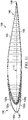
- the convex outer surface 130e can include an upper portion 130u and a ramped portion 130r as shown in FIGS. 5 and 7 .
- the upper portion 130u can be disposed adjacent to a root end 130t of the leading edge extension member 130.
- the upper portion 130u can form an inclined angle relative to the leading edge 114.
- the ramped portion 130r can be outward from and adjacent to the upper portion 130u.
- the ramped portion 130r can ramped (e.g., at an inclined angle) to meet the leading edge 114 of the blade member 108.
- the ramped portion 130r can form an inclined angle relative to the leading edge 114.
- the ramped portion 130r forms an inclined angle greater than the inclined angel of the upper portion 130u.
- the convex outer surface 130e may take on a wide variety of configurations. For example, there may be additional angled portions or other aerodynamically desirable features.
- At least one of the top and bottom sides 130a, 130b includes groove 131.
- groove 131 can be configured for locating the leading edge extension member 130 on the blade member 108.
- a groove 131 is disposed on each of the top and bottom sides 130a, 130b at the aft edges 130f of the leading edge extension member. It should be noted that the configuration of groove 131 is merely an example and that other groove shapes (e.g., slots) and geometries exist. It should be noted that in some embodiments, groove 131 is not required for locating the leading edge extension member 130 onto blade member 108.
- the leading edge extension member 130 includes the inner surface 130i that defines the hollow interior portion 130h.
- the inner surface 130i can be a concave inner surface.
- the inner surface 130i can include side surfaces 130s of the top and bottom sides 130a, 130b.
- the wall thickness of the leading edge extension member 130, as well as the geometry thereof, can be selectively tailored to produce the desired profile for the hollow interior portion 130h. For example, a leading edge extension member 130 having a greater thickness than shown in FIG. 5 would result in a smaller hollow interior portion 130h.
- the hollow interior portion 130h can be configured to receive the leading edge 114 of the blade member 108.
- the hollow interior portion 130h is generally a horseshoe shape that mimics the convex outer surface 130e; however, it should be appreciated that other embodiments may have other shapes suitable for receiving the blade member 108 therein.
- a method 160 of making a rotor blade 106 having an improved lift to drag ratio can include at least one of the following steps: a step 162 of contacting plies to a mold selectively configured to achieve the desired shape of the leading edge extension member 130, a step 164 of compacting the plies to form a leading edge extension member; a step 166 of providing a blade member 108 having a top surface118, and a bottom surface 120; a step 168 of providing a leading edge extension member 130 having an inner surface 130i defining a hollow interior portion 130h for receiving the blade member 108; a step 169 of locating the leading edge extension member 130 on the blade member; a step 170 of coupling at least a portion of the inner surface 130i of the leading edge extension member 130 to the blade member 108; a step 172 of coupling an end closeout 134 to the root end 130t of the leading edge extension member 130; and a step 174 of curing at least one of the leading edge extension member
- the plies in steps 162 and 164 can be comprised of a composite material including plies of at least one of a fabric and a tape.
- the plies are preimpregnated with an un-cured resin.
- the resin can be applied to a conventional paper liner and transferred to the ply or applied directly to the ply and then heated to melt and infuse the resin therein.
- a portion of the conventional liner can be removed, and a detection liner can be applied to one or more of the sides of a resin impregnated ply, which can assist manufacturing techniques.
- the plies can be made from a fiber that is composed of continuous filaments or fibers including one or more of glass, carbon, graphite, basalt, an aromatic polyamide (i.e. "aramid") material, a variant of an aromatic polyamide material (e.g., a polyparaphenylene terephthalamide material, such as Kevlar® by E.I. du Pont de Nemours and Company of Richmond, Va), or the like.
- aromatic polyamide i.e. "aramid”
- a variant of an aromatic polyamide material e.g., a polyparaphenylene terephthalamide material, such as Kevlar® by E.I. du Pont de Nemours and Company of Richmond, Va
- the continuous filaments or fibers described herein can include any suitable material or combination of materials.
- the resin can be a polymeric matrix or any suitable resin system, such as a thermoplastic or thermosetting resin.
- exemplary resins can include epoxy, polyimide, polyamide, bismaleimide, polyester, vinyl ester, phenolic, polyetheretherketone (PEEK), polyetherketone (PEK), polyphenylene sulfide (PPS), and the like.
- the fabric is a woven fabric.
- the tape is a unidirectional tape.
- the plies can be an intermediate modulus epoxy resin impregnated carbon fiber fabric.
- the intermediate modulus epoxy impregnated carbon fiber fabric can be stiffer than conventional composite fabrics which allows for fewer plies, which reduces the weight and manufacturing cost, while the epoxy resin system can provide tolerance to damage.
- the step 162 of contacting plies to a mold can include placing the plies in a mold and/or on a mold.
- leading edge extension member 130 is described with resin impregnated plies, other composite manufacturing process may be used.
- a resin transfer molding process can be used, which involves fabric layers, without being impregnated with resin, being placed in a selected pattern within a mold to achieve the desired shape of the leading edge extension member 130.
- resin can be transferred into a mold such that the fibers and resin are combined, and then cured to form leading edge extension member 130.
- the step 164 of compacting the plies can include applying a vacuum to the plies in or on a mold or by pressing a second mold member on the plies disposed in a mold cavity.
- the step 169 of locating the leading edge extension member 130 onto the blade member 108 can include locating using groove 131 in the leading edge extension member 130.
- the locating step 169 can include identifying a bolt 132 in the blade member 108 and positioning the groove 131 therearound to align the leading edge extension member 130 on the blade member 108.
- the top and bottom sides 130a, 130b each include a groove 131 that is positioned around a bolt 132 on the top and bottom surfaces 118, 120 of the blade member 108.
- the step 170 of coupling at least a portion of the inner surface 130i of the leading edge extension member 130 to the blade member 108 can include coupling the side surfaces 130s of the top and bottom sides 130a, 130b to the top and bottom surfaces 118, 120 of the blade member 108, respectively.
- the term “coupled” may include direct or indirect coupling by a conventional fastener or connector, including non-moving mechanical connections (e.g., adhesively connecting and/or cocuring the blade member 108, an end closeout 134, and the leading edge extension member 130).
- the side surfaces 130s of the top and bottom sides 130a, 130b are adhesively coupled to the top and bottom surfaces 118, 120, respectively, of the blade member 108.
- top and bottom sides 130a, 130b can be coupled to the top and bottom surfaces 118, 120 of the blade member 108 using a conventional fastener (e.g., screw, nut, bolt, etc.) in holes in the leading edge extension member 130 and the blade member 108.
- a conventional fastener e.g., screw, nut, bolt, etc.
- the method 160 includes a step 172 of coupling an end closeout 134 to the root end 106r of the rotor blade.
- the end closeout 134 is coupled to the root end 130t of the leading edge extension member 130 and the root end 108t of the blade member 108.
- the root end 130t is a hollow root end for receiving the end closeout 134.
- chord C can be a chord length that is defined as the distance between the farthest point on the trailing edge and the point on the leading edge where the chord length intersects the leading edge.
- chord length C3 of the rotor blade 106 is longer than the chord length C2 of the blade member 108, as shown in FIGS. 11 and 10 , respectively.
- the chord length C1 of the leading edge extension member is selectively tailored to determine the chord length C3 of the rotor blade 106.
- the chord length C1 of the leading edge extension member is about 1/20, 1/18, 1/16, 1/14, 1/12, 1/10, 1/8, 1/6, 1/4, or 1/2 the chord length C2 of the blade member 108.
- the chord length C1 is defined as a length from the point of leading edge 114 of the blade member 108 at the chord length C2 to the leading edge 136 of the leading edge extension member 130.
- the chord length C1 of the leading edge extension member 130 may take on a wide variety of configurations.
- the chord length C1 may be longer in the upper portion 130u than the chord length C1 in the ramped portion 130r.
- the chord length C3 in a root portion 140 is more than (e.g., longer) than the chord length C4 in the tip portion 142 of the rotor blade 106.
- the thickness T1 of the leading edge extension member 130 can be selectively tailored to adjust the lift to drag ration in a portion of the rotor blade.
- the thickness T1 of the leading edge extension member 130 can be more (e.g. thicker from the top and bottom sides 130a, 130b) than the thickness of the top and bottom surfaces 118, 120 of the blade member.
- the leading edge portion 144p with the leading edge extension member 130 is thicker than the trailing edge portion 146p of the rotor blade 106.
- the thickness T1 of the leading edge extension member 130 may take on a wide variety of configurations.
- the thickness T1 may be thicker in the upper portion 130u than the thickness T1 in the ramped portion 130r.
- method 100 of reducing the thickness t to chord C ratio t/C can improve the lift to drag ratio of the root portion 140 of the rotor blade 106, and thereby improves the lift to drag ratio of the rotor blade 106 during operation.
- FIG. 12 illustrates trends of airfoil thickness to chord ratio t/C versus the blade radius r/R for a rotor blade 106, a rotor blade 109 (e.g., final assembled rotor blade having the same configuration as blade member 108), and a V-22 Osprey rotor blade 111.
- An undesirable notch N1 is identified with the rotor blade 111 in an inboard portion of the blade, while the rotor blade 109 also includes an undesirable notch N2.
- Rotor blade 106 profile has a less pronounced notch N3 as compared notches N1 and N2, which correlates to improved aerodynamic performance of the rotor blade 106 as compared to rotor blades 109, 111.
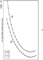
- the drag coefficient of the rotor blade 106 is reduced as compared to a rotor blade 109.
- the X-axis represents the drag coefficient and the Y-axis represents the lift coefficient.
- the rotor blade 106 including the leading edge extension member 130 demonstrates a reduced drag coefficient and increased aerodynamic efficiency of the rotor blade 106 as compared to a rotor blade 109. Accordingly, the methods described herein and the rotor blade 106 including the leading edge extension member 130 can provide an improved lift to drag ratio as compared to a rotor blade designed without these methods and the leading edge extension member 130.
- the horizontal axis represents the ratio x/C, where x is the distance to a particular point as measured back from the leading edge, and C is the total chord length from the leading edge to the trailing edge. Thus, the ratio of x/C would be 1.0 at the trailing edge.
- the vertical axes represent the ratio y/C, where y is the distance to a particular point as measured up and down from the chord axis, and C is the total chord length. Thus, the ratio of y/C would be 0.0 at the chord axis.
- FIG. 14 represents a cross-section of the root portion 140 including the leading edge extension member 130 of the rotor blade 106.
- FIG. 14 demonstrates that the leading edge extension member 130 results in an improved and reduced aerodynamic profile for the rotor blade 106 as compared to the rotor blade 109 when the thickness t and chord length C are normalized.
- aircraft 10 with plurality of rotor blades 70, 78 having the configuration and profile of rotor blade 106 can have improved performance outcomes as compared to a rotor blade without the leading edge extension member 130 including at least one of the following: reduced fuel burn in cruise; improved hover performance both in and out of ground effect; faster max cruise speed; and increased mission radius of action.
- substantially is defined as largely, but not necessarily wholly, what is specified (and includes what is specified; e.g., substantially 90 degrees includes 90 degrees), as understood by a person of ordinary skill in the art.
- the terms “substantially,” “approximately,” and “about” may be substituted with “within [a percentage] of” what is specified, where the percentage includes 0.1, 1, 5, and 10 percent.
Landscapes
- Engineering & Computer Science (AREA)
- Aviation & Aerospace Engineering (AREA)
- Mechanical Engineering (AREA)
- Combustion & Propulsion (AREA)
- Life Sciences & Earth Sciences (AREA)
- Sustainable Development (AREA)
- Sustainable Energy (AREA)
- Chemical & Material Sciences (AREA)
- General Engineering & Computer Science (AREA)
- Fluid Mechanics (AREA)
- Physics & Mathematics (AREA)
- Turbine Rotor Nozzle Sealing (AREA)
- Wind Motors (AREA)
Abstract
Description
- This application claims priority to
U.S. provisional patent application number 62/521,393, filed June 17, 2017 - The present disclosure relates to aircrafts and, more particularly, to aircraft rotor blades.
- The root portion of a rotor blade for a vertical take-off and landing (VTOL) aircraft experiences a wide range of aerodynamic conditions from hover (low relative velocity, high angle of attack) to cruise (high relative velocity, zero angle of attack). The conventional profile of the root portion of the rotor blade is typically thicker than the tip portion to accommodate hub attachment, bearings, and clearance through a large feathering motion range. The profile of the root portion of the rotor blade with a large thickness t to chord C ratio, see
FIG. 4A , cannot efficiently handle the wide range of operating conditions that the blade experiences due to early chordwise separation and subsequent rise in profile drag. - In some VTOL aircraft, namely the V-22 Osprey, there is a removable fairing positioned over the blade grip to improve the aerodynamics of the aircraft during operation. However, the removable fairing is associated with movable portions or is removed to not interfere with the folding of the rotor blades during stowage of the aircraft. Additionally, a removable fairing on or associated with a rotor blade is undesirable as the removable fairing can add weight to the blade and decrease efficiency during operation of the aircraft.
- There is a need to improve the aerodynamic efficiency and performance of a rotor blade for a VTOL aircraft.
- In a first aspect, there is provided a method for improving a lift to drag ratio of a rotor blade, including providing a blade member having a leading edge and a trailing edge; providing a leading edge extension member; and coupling the leading edge extension member to a portion of the leading edge of the blade member to form the rotor blade.
- In an embodiment, the blade member includes a root portion and a tip portion, the leading edge extension member is disposed on the root portion.
- In one embodiment, the lift to drag ratio of the root portion of the rotor blade is determined by selectively tailoring at least one of a chord length, a thickness, and a shape of the leading edge extension member.
- In still another embodiment, the leading edge extension member includes an inner surface that defines a hollow interior portion for receiving the blade member.
- In yet another embodiment, the step of coupling includes coupling the blade member to at least a portion of the inner surface of the leading edge extension member.
- In an exemplary embodiment, the blade member has an airfoil geometry including at least one of the following: a NACA geometry, a modified NACA geometry, and combinations thereof.
- In an another embodiment, the leading edge extension member has a root end, and the steps further include coupling an end closeout to the root end of the leading edge extension member.
- In still another embodiment, the method further includes locating the leading edge extension member on the blade member using a groove in the leading edge extension member.
- In a second aspect, there is provided a rotor blade including a blade member having a leading edge, and a trailing edge; and a leading edge extension member disposed on the leading edge of the blade member, wherein the leading edge extension member is configured to extend the chord length of at least a portion of the rotor blade.
- In another embodiment, the blade member includes a root portion and a tip portion, the leading edge extension member is disposed on the root portion of the blade member.
- In yet another embodiment, the chord length of the root portion of the blade member is more than the tip portion of the blade member.
- In still another embodiment, wherein the blade member has an airfoil geometry including at least one of the following: a NACA geometry, a modified NACA geometry, and combinations thereof.
- In an embodiment, the leading edge extension member includes a top side; a bottom side; and a curved portion disposed between the top side and bottom side; wherein the top side, bottom side, and the curved portion form a convex outer surface configured to extend at least a portion of the chord length of the rotor blade.
- In another embodiment, the ramped portion has an inclined angle greater than an inclined angle of the upper portion.
- In another embodiment, the leading edge extension member further includes a groove disposed on at least one of the top side and the bottom side configured for locating the leading edge extension member on the blade member.
- In an embodiment, the leading edge extension member further includes an inner surface that defines a hollow interior portion for receiving the blade member.
- In still another embodiment, the rotor blade further includes an end closeout disposed on a root end of the leading edge extension member.
- In a third aspect, there is provided a leading edge extension member for a rotor blade including a convex exterior surface configured to extend at least a portion of the chord length of the rotor blade.
- In an embodiment, the convex exterior surface includes a ramped portion and an upper portion.
- In some embodiments, the ramped portion has an inclined angle greater than an inclined angle of the upper portion.
- In another embodiment, the convex exterior surface includes a top side, a bottom side, and a curved portion disposed between the top side and the bottom side.
- In one embodiment, the leading edge extension member further includes a groove disposed on at least one of the top side and the bottom side.
- In yet another embodiment, the leading edge extension member further includes a hollow interior portion configured to receive a blade member.
- In a fourth aspect, there is provided a method for designing a rotor blade for generating improved lift and reduced drag as compared to a conventional rotor blade including increasing the chord length of the root portion of the rotor blade by disposing a leading edge extension member on the leading edge of a blade member.
- In a fifth aspect, there is provided a method for increasing the chord length C2 in a root portion of a rotor blade by coupling a leading edge extension member having a hollow interior portion to a leading edge of a blade member.
- In a sixth aspect, there is provided a method of improving the lift to drag ratio of a rotor blade including providing a blade member having a root portion, a tip portion, a leading edge, and a trailing edge, providing a leading edge extension member having a hollow interior portion for receiving the blade member; selectively tailoring the leading edge extension member to determine the lift to drag ratio of a rotor blade; coupling the leading edge extension member to the root portion of the blade member to form the rotor blade.
- In a seventh aspect, there is provided a method of manufacturing including contacting plies to a mold selectively configured to achieve the desired shape of the leading edge extension member; compacting the plies to form a pre-cured leading edge extension member; providing a blade member having a top surface and a bottom surface; providing a pre-cured leading edge extension member having an upper and lower inner surface defining a hollow interior portion for receiving the blade member; adhesively coupling the upper and lower inner surfaces of the leading edge extension member to the top and bottom surfaces of the blade member; coupling an end closeout to the root end of the leading edge extension member; and curing at least one of the leading edge extension member, the end closeout, and the blade member.
- Other aspects, features, and advantages will become apparent from the following detailed description when taken in conjunction with the accompanying drawings, which are a part of this disclosure and which illustrate, by way of example, principles of the inventions disclosed.
- The novel features believed characteristic of the embodiments of the present disclosure are set forth in the appended claims. However, the embodiments themselves, as well as a preferred mode of use, and further objectives and advantages thereof, will best be understood by reference to the following detailed description when read in conjunction with the accompanying drawings, wherein:
-
FIG. 1 is a perspective view of an aircraft, according to one example embodiment; -
FIG. 2 is another perspective view of an aircraft, according to one example embodiment; -
FIG. 3 is a side view of a rotor assembly, according to one example embodiment; -
FIG. 4A is a schematic of a rotor blade to illustrate the thickness t to chord C ratio; -
FIGS. 4B-4C are flowcharts illustrating methods of improving the lift to drag ratio for a rotor blade, according to illustrative embodiments; -
FIG. 4D is a flowchart illustrating methods of making a rotor blade having an improved lift to drag ratio, according to an illustrative embodiment; -
FIG. 4E is a flowchart illustrating a method for designing a cross-section of a root portion of a rotor blade to improve the lift to drag ratio, according to illustrative embodiments; -
FIG. 5 is a perspective view of a leading edge extension member, according to an exemplary embodiment; -
FIG. 6 is a top view of a rotor blade, according to one example embodiment; -
FIG. 7 is a partially removed detail view of the rotor blade inFIG. 6 including the grip and pitch horn, according to an illustrative embodiment; -
FIG. 8 is a perspective view of a root portion of a rotor blade, according to an exemplary embodiment; -
FIG. 9 is a top view of a blade member, according to an example embodiment; -
FIG. 10 is a cross-sectional view of a leading edge extension member and a blade member, according to an illustrative embodiment; -
FIG. 11 is a cross-sectional view of a rotor blade, according to an illustrative embodiment; -
FIG. 12 shows an exemplary graph illustrating trends of airfoil thickness and blade radius of arotor blade 106, arotor blade 109, and a rotor blade for aconventional tiltrotor aircraft 111, according to an illustrative embodiment; -
FIG. 13 shows an exemplary graph charting lift coefficient and drag coefficient of arotor blade 106 and arotor blade 109, according to an illustrative embodiment; and -
FIG. 14 shows an exemplary graph charting a horizontal axis and chord X/C versus a vertical axis and chord Y/C of arotor blade 106 and arotor blade 109; according to an illustrative embodiment. - Illustrative embodiments of the apparatuses and methods to improve lift to drag ratio of a rotor blade are described below. In the interest of clarity, all features of an actual implementation may not be described in this specification. It will of course be appreciated that in the development of any such actual embodiment, numerous implementation-specific decisions must be made to achieve the developer's specific goals, such as compliance with system-related and business-related constraints, which will vary from one implementation to another. Moreover, it will be appreciated that such a development effort might be complex and time-consuming but would nevertheless be a routine undertaking for those of ordinary skill in the art having the benefit of this disclosure.
- In the specification, reference may be made to the spatial relationships between various components and to the spatial orientation of various aspects of components as the devices are depicted in the attached drawings. However, as will be recognized by those skilled in the art after a complete reading of the present application, the devices, members, apparatuses, etc. described herein may be positioned in any desired orientation. Thus, the use of terms such as "above," "below," "upper," "lower," or other like terms to describe a spatial relationship between various components or to describe the spatial orientation of aspects of such components should be understood to describe a relative relationship between the components or a spatial orientation of aspects of such components, respectively, as the devices, members, apparatuses, etc. described herein may be oriented in any desired direction.
-
FIGS. 1-2 depictaircraft 10 as a tiltrotor aircraft.FIGS. 1-2 depict three mutually orthogonal directions X, Y, and Z forming a three-dimensional frame of reference XYZ.Longitudinal axis X 14 corresponds to the roll axis that extends through the center ofaircraft 10 in the fore and after directions.Transverse axis Y 18 is perpendicular tolongitudinal axis 14 and corresponds to the pitch axis (also known as a control pitch axis or "CPA"). The X-Y plane is considered to be "horizontal."Vertical axis Z 22 is the yaw axis and is oriented perpendicularly with respect to the X-Y plane. The X-Z plane and Y-Z plane are considered to be "vertical." -
Aircraft 10 includesfuselage 26 as a central main body.Fuselage 26 extends parallel tolongitudinal axis 14 from a fuselagefront end 30 to a fuselagerear end 34.Aircraft 10 further includestail member 38 extending from fuselagerear end 34 offuselage 26.Aircraft 10 includeswing 42 andwing 46 extending fromfuselage 26 substantially parallel totransverse axis Y 18.Wing 42 is coupled topropulsion system 50, andwing 46 is coupled topropulsion system 54.Propulsion system 50 includesrotor assembly 58, andpropulsion system 54 includesrotor assembly 62.Rotor assembly 58 includesrotor hub 66 and plurality ofrotor blades 70 extending fromrotor hub 66 and configured to rotate aboutaxis 72. Similarly,rotor assembly 62 includesrotor hub 74 and plurality ofrotor blades 78 extending fromrotor hub 74 and configured to rotate aboutaxis 80. Each ofrotor assemblies propulsion system 50 topropulsion system 54 or a segmented driveshaft separated by a gearbox. -
Rotor assemblies aircraft 10. For example,FIG. 1 illustratesaircraft 10 in a first configuration, in whichpropulsion systems aircraft 10, if activated. In the embodiment shown inFIG. 1 ,propulsion systems aircraft 10 moves substantially in the Z direction ("helicopter mode"). In the embodiment shown inFIG. 1 ,aircraft 10 further includeslanding gear 82 with whichaircraft 10 can contact a landing surface. -
FIG. 2 illustratesaircraft 10 in a second configuration, in whichpropulsion systems aircraft 10, if activated. In the embodiment shown inFIG. 2 ,propulsion systems aircraft 10 moves substantially in the X direction ("airplane mode"). In the second configuration depicted inFIG. 2 ,wings aircraft 10. Though not depicted inFIGS. 1-2 ,propulsion systems -
FIGS. 3-14 relate to methods and apparatuses for improving the aerodynamic performance of a rotor blade for a VTOL aircraft. Any method, apparatus, or associated rotor blade components depicted inFIGS. 3-14 and/or described herein can be used in combination withaircraft 10 depicted inFIGS. 1-2 to operate as described. Additionally, the methods, apparatuses, and associated rotor blade components described herein can be used with any aircraft configured or configurable to include one or more rotor assemblies, including helicopters, tilt wing aircrafts, unmanned aerial vehicles (UAVs), and other vertical lift aircrafts, or can further be used with any device configured or configurable to include a rotor blade, including devices with propellers, windmills, and wind turbines. - The methods, apparatuses, and associated rotor blade components described herein involve improving the lift to drag ratio of a
rotor blade 106 for the plurality ofrotor blades method 100 improves the performance of a VTOL aircraft by improving a lift to drag ratio of a rotor blade. In an embodiment, referring toFIG. 4B , themethod 100 includes astep 102 of providing ablade member 108 having aroot portion 110, atip portion 112, aleading edge 114, and a trailingedge 116. Themethod 100 can include the following: astep 104 such that a leadingedge extension member 130 is provided, and, instep 107, the leadingedge extension member 130 is coupled to a portion of theleading edge 114 of theblade member 108 to form therotor blade 106. - In an embodiment, the
blade member 108 can have an airfoil geometry including at least one of the following: a National Advisory Committee for Aeronautics (NACA) geometry, a modified NACA geometry, and combinations thereof. The NACA geometry can be identified using the conventional 4-digit definitions. The modified NACA geometry can be variations of the NACA geometry. The modified NACA geometry can include three dimensional surfaces of theblade member 108 comprised of various two dimensional sections across the span of theblade member 108. In some embodiments, theblade member 108 can include at a portion having a NACA geometry and a portion having a modified NACA geometry. Those skilled in the art will appreciate that any suitable cross-sectional airfoil profile can be used, whether a NACA geometry or a modified NACA geometry, without departing from the spirit and scope of the disclosure. -
Rotor blade 106 is shown inFIGS. 3 ,6-8 , and11 .Rotor blade 106 includes aroot portion 140, aroot end 140t, atip portion 142, atip end 142t, aleading edge 144, a trailingedge 146, atop surface 148, and abottom surface 149. In an embodiment,root portion 140 is disposed adjacent to rootend 140t. In an embodiment,root portion 140 is a portion inboard of thetip portion 142. In an embodiment,root portion 140 is a portion that is about ½ or less the spanwise length of therotor blade 106. In some embodiments,root portion 140 is a first inboard portion that extends in the first ½, ⅓, ¼ or 1/5 of the length of therotor blade 106. In an embodiment, the spanwise length of therotor blade 106 is fromroot end 140t to 142t. In an embodiment, the leadingedge extension member 130 extends partially along the spanwise length of therotor blade 106.Rotor blade 106 may be required to twist about a pitch change axis S, which can broadly be a spanwise axis. The pitch change axis S can define aleading edge portion 144p and a trailingedge portion 146p of therotor blade 106. - In an embodiment,
rotor blade 106 includes leadingedge extension member 130 disposed on at least a portion of theleading edge 114 of theblade member 108. In some embodiments, the leadingedge extension member 130 is disposed on theroot portion 140 of therotor blade 106. In a preferred embodiment, leadingedge extension member 130 is disposed in theleading edge portion 144p of therotor blade 106. - In a
method 150, shown inFIG. 4C , there can be a method for improving the lift to drag ratio of arotor blade 106, including astep 152 of providing ablade member 108 having aroot portion 110, atip portion 112, aleading edge 114, and a trailingedge 116; astep 154 of providing a leadingedge extension member 130 having aninner surface 130i defining a hollowinterior portion 130h for receiving theblade member 108; astep 156 of selectively tailoring the leadingedge extension member 130 to reduce the drag of therotor blade 106; and astep 158 of coupling theroot portion 110 of theblade member 108 to theinner surface 130i of the leadingedge extension member 130 to form therotor blade 106. - The lift to drag ratio of the
root portion 140 of therotor blade 106 and/or theentire rotor blade 106 can be determined by selectively tailoring at least one of the chord length C1, thickness T1, and shape of the leadingedge extension member 130. In an embodiment, the chord length C3 of theroot portion 140 of therotor blade 106 is selectively tailored by the leadingedge extension member 130 as shown inFIGS. 10-11 . - In an embodiment illustrated in
FIG. 4E , there is amethod 180 for designing a cross-section of arotor blade 106 to improve the lift to drag ratio thereof including the step 182 of increasing the chord length C3 in theroot portion 140 of therotor blade 106 by coupling a leadingedge extension member 130 to aleading edge 114 of ablade member 108. - Referring to the embodiment shown in
FIG. 5 , the leadingedge extension member 130 can include top andbottom sides curved portion 130c that form a convexouter surface 130e. In an embodiment, the convexouter surface 130e can have an C-shaped profile. The top andbottom sides blade member 108 when assembled asrotor blade 106. Thecurved portion 130c can generally mimic the curvature of theleading edge 114 of theblade member 108. Thecurved portion 130c can be an inwardly curved to provide the desired aerodynamic properties for therotor blade 106. - The convex
outer surface 130e can include anupper portion 130u and a rampedportion 130r as shown inFIGS. 5 and7 . Theupper portion 130u can be disposed adjacent to aroot end 130t of the leadingedge extension member 130. Theupper portion 130u can form an inclined angle relative to theleading edge 114. The rampedportion 130r can be outward from and adjacent to theupper portion 130u. The rampedportion 130r can ramped (e.g., at an inclined angle) to meet theleading edge 114 of theblade member 108. The rampedportion 130r can form an inclined angle relative to theleading edge 114. In a preferred embodiment, the rampedportion 130r forms an inclined angle greater than the inclined angel of theupper portion 130u. It should be appreciated that the convexouter surface 130e may take on a wide variety of configurations. For example, there may be additional angled portions or other aerodynamically desirable features. - In an embodiment, at least one of the top and
bottom sides groove 131. In some embodiments, groove 131 can be configured for locating the leadingedge extension member 130 on theblade member 108. In a preferred embodiment, agroove 131 is disposed on each of the top andbottom sides aft edges 130f of the leading edge extension member. It should be noted that the configuration ofgroove 131 is merely an example and that other groove shapes (e.g., slots) and geometries exist. It should be noted that in some embodiments,groove 131 is not required for locating the leadingedge extension member 130 ontoblade member 108. - In some embodiments, the leading
edge extension member 130 includes theinner surface 130i that defines the hollowinterior portion 130h. Theinner surface 130i can be a concave inner surface. Theinner surface 130i can includeside surfaces 130s of the top andbottom sides edge extension member 130, as well as the geometry thereof, can be selectively tailored to produce the desired profile for the hollowinterior portion 130h. For example, a leadingedge extension member 130 having a greater thickness than shown inFIG. 5 would result in a smaller hollowinterior portion 130h. The hollowinterior portion 130h can be configured to receive theleading edge 114 of theblade member 108. In the illustrated embodiment, the hollowinterior portion 130h is generally a horseshoe shape that mimics the convexouter surface 130e; however, it should be appreciated that other embodiments may have other shapes suitable for receiving theblade member 108 therein. - Referring to
FIG. 4D , there is amethod 160 of making arotor blade 106 having an improved lift to drag ratio, can include at least one of the following steps: astep 162 of contacting plies to a mold selectively configured to achieve the desired shape of the leadingedge extension member 130, astep 164 of compacting the plies to form a leading edge extension member; astep 166 of providing ablade member 108 having a top surface118, and abottom surface 120; astep 168 of providing a leadingedge extension member 130 having aninner surface 130i defining a hollowinterior portion 130h for receiving theblade member 108; astep 169 of locating the leadingedge extension member 130 on the blade member; astep 170 of coupling at least a portion of theinner surface 130i of the leadingedge extension member 130 to theblade member 108; astep 172 of coupling an end closeout 134 to theroot end 130t of the leadingedge extension member 130; and astep 174 of curing at least one of the leadingedge extension member 130, the end closeout 134, and theblade member 108. - The plies in
steps - In an embodiment, the plies can be an intermediate modulus epoxy resin impregnated carbon fiber fabric. The intermediate modulus epoxy impregnated carbon fiber fabric can be stiffer than conventional composite fabrics which allows for fewer plies, which reduces the weight and manufacturing cost, while the epoxy resin system can provide tolerance to damage.
- The
step 162 of contacting plies to a mold can include placing the plies in a mold and/or on a mold. It should be appreciated that even though leadingedge extension member 130 is described with resin impregnated plies, other composite manufacturing process may be used. For example, a resin transfer molding process can be used, which involves fabric layers, without being impregnated with resin, being placed in a selected pattern within a mold to achieve the desired shape of the leadingedge extension member 130. Further, resin can be transferred into a mold such that the fibers and resin are combined, and then cured to form leadingedge extension member 130. - The
step 164 of compacting the plies can include applying a vacuum to the plies in or on a mold or by pressing a second mold member on the plies disposed in a mold cavity. - The
step 169 of locating the leadingedge extension member 130 onto theblade member 108 can include locating usinggroove 131 in the leadingedge extension member 130. In a particular embodiment, the locatingstep 169 can include identifying abolt 132 in theblade member 108 and positioning thegroove 131 therearound to align the leadingedge extension member 130 on theblade member 108. In a preferred embodiment, the top andbottom sides groove 131 that is positioned around abolt 132 on the top andbottom surfaces blade member 108. - The
step 170 of coupling at least a portion of theinner surface 130i of the leadingedge extension member 130 to theblade member 108 can include coupling the side surfaces 130s of the top andbottom sides bottom surfaces blade member 108, respectively. As used herein, the term "coupled" may include direct or indirect coupling by a conventional fastener or connector, including non-moving mechanical connections (e.g., adhesively connecting and/or cocuring theblade member 108, an end closeout 134, and the leading edge extension member 130). In an embodiment, the side surfaces 130s of the top andbottom sides bottom surfaces blade member 108. The top andbottom sides bottom surfaces blade member 108 using a conventional fastener (e.g., screw, nut, bolt, etc.) in holes in the leadingedge extension member 130 and theblade member 108. - In an embodiment, the
method 160 includes astep 172 of coupling an end closeout 134 to the root end 106r of the rotor blade. In an embodiment, the end closeout 134 is coupled to theroot end 130t of the leadingedge extension member 130 and theroot end 108t of theblade member 108. In some embodiments, theroot end 130t is a hollow root end for receiving the end closeout 134. There can also be astep 174 including curing at least one of the leadingedge extension member 130, the end closeout 134, andblade member 108. - An embodiment provides modifying a chord length of a
rotor blade 106 using a leadingedge extension member 130 to selectively tailor the thickness t to chord C ratio t/C, as shown inFIG 4A . Chord C can be a chord length that is defined as the distance between the farthest point on the trailing edge and the point on the leading edge where the chord length intersects the leading edge. In an embodiment, the chord length C3 of therotor blade 106 is longer than the chord length C2 of theblade member 108, as shown inFIGS. 11 and10 , respectively. In an embodiment, the chord length C1 of the leading edge extension member is selectively tailored to determine the chord length C3 of therotor blade 106. In an embodiment, the chord length C1 of the leading edge extension member is about 1/20, 1/18, 1/16, 1/14, 1/12, 1/10, 1/8, 1/6, 1/4, or 1/2 the chord length C2 of theblade member 108. The chord length C1 is defined as a length from the point of leadingedge 114 of theblade member 108 at the chord length C2 to theleading edge 136 of the leadingedge extension member 130. It should be appreciated that the chord length C1 of the leadingedge extension member 130 may take on a wide variety of configurations. For example, the chord length C1 may be longer in theupper portion 130u than the chord length C1 in the rampedportion 130r. In an exemplary embodiment, the chord length C3 in aroot portion 140 is more than (e.g., longer) than the chord length C4 in thetip portion 142 of therotor blade 106. - In another embodiment, the thickness T1 of the leading
edge extension member 130 can be selectively tailored to adjust the lift to drag ration in a portion of the rotor blade. For example, the thickness T1 of the leadingedge extension member 130 can be more (e.g. thicker from the top andbottom sides bottom surfaces edge portion 144p with the leadingedge extension member 130 is thicker than the trailingedge portion 146p of therotor blade 106. It should be appreciated that the thickness T1 of the leadingedge extension member 130 may take on a wide variety of configurations. For example, the thickness T1 may be thicker in theupper portion 130u than the thickness T1 in the rampedportion 130r. - In an embodiment,
method 100 of reducing the thickness t to chord C ratio t/C can improve the lift to drag ratio of theroot portion 140 of therotor blade 106, and thereby improves the lift to drag ratio of therotor blade 106 during operation.FIG. 12 illustrates trends of airfoil thickness to chord ratio t/C versus the blade radius r/R for arotor blade 106, a rotor blade 109 (e.g., final assembled rotor blade having the same configuration as blade member 108), and a V-22Osprey rotor blade 111. An undesirable notch N1 is identified with therotor blade 111 in an inboard portion of the blade, while therotor blade 109 also includes an undesirable notch N2.Rotor blade 106 profile has a less pronounced notch N3 as compared notches N1 and N2, which correlates to improved aerodynamic performance of therotor blade 106 as compared torotor blades - Referring to
FIG. 13 , the drag coefficient of therotor blade 106 is reduced as compared to arotor blade 109. The X-axis represents the drag coefficient and the Y-axis represents the lift coefficient. Therotor blade 106 including the leadingedge extension member 130 demonstrates a reduced drag coefficient and increased aerodynamic efficiency of therotor blade 106 as compared to arotor blade 109. Accordingly, the methods described herein and therotor blade 106 including the leadingedge extension member 130 can provide an improved lift to drag ratio as compared to a rotor blade designed without these methods and the leadingedge extension member 130. - Referring to
FIG. 14 , the horizontal axis represents the ratio x/C, where x is the distance to a particular point as measured back from the leading edge, and C is the total chord length from the leading edge to the trailing edge. Thus, the ratio of x/C would be 1.0 at the trailing edge. In a similar fashion, the vertical axes represent the ratio y/C, where y is the distance to a particular point as measured up and down from the chord axis, and C is the total chord length. Thus, the ratio of y/C would be 0.0 at the chord axis.FIG. 14 represents a cross-section of theroot portion 140 including the leadingedge extension member 130 of therotor blade 106.FIG. 14 demonstrates that the leadingedge extension member 130 results in an improved and reduced aerodynamic profile for therotor blade 106 as compared to therotor blade 109 when the thickness t and chord length C are normalized. - The methods described herein can advantageously provide at least one of the following: a delay in chordwise separation of a rotor blade, a reduction of profile drag in the rotor blades, and does not require removal of the leading edge extension member during folding. In an exemplary embodiment,
aircraft 10 with plurality ofrotor blades rotor blade 106 can have improved performance outcomes as compared to a rotor blade without the leadingedge extension member 130 including at least one of the following: reduced fuel burn in cruise; improved hover performance both in and out of ground effect; faster max cruise speed; and increased mission radius of action. - It may be advantageous to set forth definitions of certain words and phrases used in this patent document.
- The terms "a" and "an" are defined as one or more unless this disclosure explicitly requires otherwise.
- The term "substantially" is defined as largely, but not necessarily wholly, what is specified (and includes what is specified; e.g., substantially 90 degrees includes 90 degrees), as understood by a person of ordinary skill in the art. In any disclosed embodiment, the terms "substantially," "approximately," and "about" may be substituted with "within [a percentage] of" what is specified, where the percentage includes 0.1, 1, 5, and 10 percent.
- Use of broader terms such as comprises, includes, and has (and any derivatives of such terms, such as comprising, including, and having) should be understood to provide support for narrower terms, such as consisting of, consisting essentially of, and comprised substantially of. Thus, in any of the claims, the term "consisting of," "consisting essentially of," or "comprised substantially of" can be substituted for any of the open-ended linking verbs recited above in order to change the scope of a given claim from what it would otherwise be using the open-ended linking verb.
- At least one embodiment is disclosed and variations, combinations, and/or modifications of the embodiment(s) and/or features of the embodiment(s) made by a person having ordinary skill in the art are within the scope of the disclosure. Alternative embodiments that result from combining, integrating, and/or omitting features of the embodiment(s) are also within the scope of the disclosure. The feature or features of one embodiment may be applied to other embodiments to achieve still other embodiments, even though not described, unless expressly prohibited by this disclosure or the nature of the embodiments. The scope of protection is not limited by the description set out above but is defined by the claims that follow, the scope including all equivalents of the subject matter of the claims. Each and every claim is incorporated as further disclosure into the specification and the claims are embodiment(s) of the present invention.
Claims (16)
- A method for improving a lift to drag ratio of a rotor blade, comprising:providing a blade member having a leading edge and a trailing edge;providing a leading edge extension member; andcoupling the leading edge extension member to a portion of the leading edge of the blade member to form the rotor blade.
- The method according to claim 1, wherein the blade member comprises a root portion and a tip portion, the leading edge extension member is disposed on the root portion.
- The method according to claim 2, wherein the lift to drag ratio of the root portion of the rotor blade is determined by selectively tailoring at least one of a chord length, a thickness, and a shape of the leading edge extension member.
- The method according to claim 1 or of claim 2 or of claim 3, wherein the leading edge extension member comprises an inner surface that defines a hollow interior portion for receiving the blade member, and optionally or preferably wherein the step of coupling comprises coupling the blade member to at least a portion of the inner surface of the leading edge extension member.
- The method according to claim 1 or of any of claims 2 to 4, wherein the leading edge extension member has a root end, further comprising:coupling an end closeout to the root end of the leading edge extension member.
- The method according to claim 1 or of any of claims 2 to 5, further comprising:locating the leading edge extension member on the blade member using a groove in the leading edge extension member.
- A rotor blade comprising:a blade member having a leading edge, and a trailing edge; anda leading edge extension member disposed on the leading edge of the blade member,wherein the leading edge extension member is configured to extend a chord length of at least a portion of the rotor blade.
- The rotor blade according to claim 7, wherein the blade member comprises a root portion and a tip portion, the leading edge extension member is disposed on the root portion of the blade member, and optionally or preferably wherein the chord length of the root portion of the blade member is more than the tip portion of the blade member.
- The rotor blade according to claim 7 or claim 8, wherein the blade member has an airfoil geometry comprising at least one of the following: a NACA geometry, a modified NACA geometry, and combinations thereof.
- A leading edge extension member for a rotor blade comprising:a top side;a bottom side; anda curved portion disposed between the top side and bottom sidewherein the top side, the bottom side, and the curved portion form a convex outer surface configured to extend at least a portion of the chord length of the rotor blade.
- The rotor blade according to claim 7 or claim 8 or claim 9, wherein the leading edge extension member comprises a convex exterior surface including a ramped portion and an upper portion; or
the leading edge extension member according to claim 10, wherein the convex exterior surface comprises a ramped portion and an upper portion. - The rotor blade according to claim 11 or the leading edge extension according to claim 11, wherein the ramped portion has an inclined angle greater than an inclined angle of the upper portion.
- The rotor blade according to claim 11 or claim 12, wherein the convex exterior surface comprises a top side, a bottom side, and a curved portion disposed between the top side and the bottom side.
- The rotor blade according to claim 13, wherein the leading edge extension member further comprises a groove disposed on at least one of the top side and the bottom side, the groove configured for locating the leading edge extension member on the blade member; or
the leading edge extension member according to claim 10 or of claim 11 or of claim 12, further comprising a groove disposed on at least one of the top side and the bottom side. - The rotor blade according to claim 7 or of any preceding rotor blade claim, wherein the leading edge extension member further comprises a hollow interior portion configured to receive the blade member; or
the leading edge extension member according to claim 10 or of any preceding leading edge extension member claim, further comprising a hollow interior portion configured to receive a blade member. - The rotor blade according to claim 15 or the leading edge extension member of claim 15, further comprising an end closeout disposed on a root end of the leading edge extension member.
Applications Claiming Priority (2)
| Application Number | Priority Date | Filing Date | Title |
|---|---|---|---|
| US201762521393P | 2017-06-17 | 2017-06-17 | |
| US15/843,039 US10604234B2 (en) | 2017-06-17 | 2017-12-15 | Method and apparatus to improve lift to drag ratio of a rotor blade |
Publications (2)
| Publication Number | Publication Date |
|---|---|
| EP3415422A1 true EP3415422A1 (en) | 2018-12-19 |
| EP3415422B1 EP3415422B1 (en) | 2019-07-31 |
Family
ID=61256619
Family Applications (1)
| Application Number | Title | Priority Date | Filing Date |
|---|---|---|---|
| EP18157738.8A Active EP3415422B1 (en) | 2017-06-17 | 2018-02-20 | Method and apparatus to improve lift to drag ratio of a rotor blade |
Country Status (3)
| Country | Link |
|---|---|
| US (1) | US10604234B2 (en) |
| EP (1) | EP3415422B1 (en) |
| CA (1) | CA2995889C (en) |
Cited By (2)
| Publication number | Priority date | Publication date | Assignee | Title |
|---|---|---|---|---|
| US10604234B2 (en) | 2017-06-17 | 2020-03-31 | Bell Helicopter Textron Inc. | Method and apparatus to improve lift to drag ratio of a rotor blade |
| USD891351S1 (en) | 2017-12-15 | 2020-07-28 | Bell Helicopter Textron Inc. | Rotor blade |
Citations (4)
| Publication number | Priority date | Publication date | Assignee | Title |
|---|---|---|---|---|
| WO2004067380A1 (en) * | 2003-01-23 | 2004-08-12 | Bell Helicopter Textron Inc. | Proprotor blade with leading edge slot |
| WO2007105174A1 (en) * | 2006-03-14 | 2007-09-20 | Tecsis Tecnologia E Sistemas Avançados Ltda | Multi-element blade with aerodynamic profiles |
| EP2078852A2 (en) * | 2008-01-11 | 2009-07-15 | Siemens Aktiengesellschaft | Wind turbine rotor blade |
| EP2341245A2 (en) * | 2009-12-30 | 2011-07-06 | General Electric Company | Apparatus for increasing lift on wind turbine blade |
Family Cites Families (14)
| Publication number | Priority date | Publication date | Assignee | Title |
|---|---|---|---|---|
| US4976587A (en) * | 1988-07-20 | 1990-12-11 | Dwr Wind Technologies Inc. | Composite wind turbine rotor blade and method for making same |
| US8016566B2 (en) | 2006-08-03 | 2011-09-13 | Bell Helicopter Textron Inc. | High performance low noise rotorcraft blade aerodynamic design |
| ES2333929B1 (en) | 2007-10-18 | 2011-01-31 | Fundacion Cener-Ciemat | REMOVABLE PROTECTION OF THE ATTACK EDGE ON A WINDER BLADE. |
| GB2464163A (en) * | 2009-02-25 | 2010-04-14 | Vestas Wind Sys As | Variable leading edge wind turbine blade |
| US9120564B1 (en) * | 2010-09-09 | 2015-09-01 | Groen Brothers Aviation, Inc. | Tip jet attachment apparatus and method |
| US9056674B2 (en) * | 2010-09-09 | 2015-06-16 | Groen Brothers Aviation, Inc. | Detachable rotor blade fairing apparatus and method |
| CA2718026A1 (en) | 2010-10-19 | 2012-04-19 | Universite Du Quebec A Chicoutimi | Vibration-based ice protection sleeve |
| US8403642B2 (en) * | 2011-09-27 | 2013-03-26 | General Electric Company | Wind turbine rotor blade assembly with root curtain |
| US8622707B2 (en) * | 2011-12-19 | 2014-01-07 | General Electric Company | Root attachment for a rotor blade assembly |
| US9677538B2 (en) | 2012-02-09 | 2017-06-13 | General Electric Company | Wind turbine rotor blade assembly with root extension panel and method of assembly |
| US10669021B2 (en) | 2012-09-14 | 2020-06-02 | Textron Innovations Inc. | Method of optimizing and customizing rotor blade structural properties by tailoring large cell composite core and a rotor blade incorporating the same |
| US9638048B2 (en) * | 2013-03-15 | 2017-05-02 | Bell Helicopter Textron Inc. | Systems and methods of constructing composite assemblies |
| EP3533816B1 (en) | 2014-11-10 | 2024-07-17 | Polytech A/S | Preformed protective cover and wind turbine blade |
| US10604234B2 (en) | 2017-06-17 | 2020-03-31 | Bell Helicopter Textron Inc. | Method and apparatus to improve lift to drag ratio of a rotor blade |
-
2017
- 2017-12-15 US US15/843,039 patent/US10604234B2/en active Active
-
2018
- 2018-02-20 EP EP18157738.8A patent/EP3415422B1/en active Active
- 2018-02-21 CA CA2995889A patent/CA2995889C/en active Active
Patent Citations (4)
| Publication number | Priority date | Publication date | Assignee | Title |
|---|---|---|---|---|
| WO2004067380A1 (en) * | 2003-01-23 | 2004-08-12 | Bell Helicopter Textron Inc. | Proprotor blade with leading edge slot |
| WO2007105174A1 (en) * | 2006-03-14 | 2007-09-20 | Tecsis Tecnologia E Sistemas Avançados Ltda | Multi-element blade with aerodynamic profiles |
| EP2078852A2 (en) * | 2008-01-11 | 2009-07-15 | Siemens Aktiengesellschaft | Wind turbine rotor blade |
| EP2341245A2 (en) * | 2009-12-30 | 2011-07-06 | General Electric Company | Apparatus for increasing lift on wind turbine blade |
Cited By (3)
| Publication number | Priority date | Publication date | Assignee | Title |
|---|---|---|---|---|
| US10604234B2 (en) | 2017-06-17 | 2020-03-31 | Bell Helicopter Textron Inc. | Method and apparatus to improve lift to drag ratio of a rotor blade |
| USD891351S1 (en) | 2017-12-15 | 2020-07-28 | Bell Helicopter Textron Inc. | Rotor blade |
| USD907559S1 (en) | 2017-12-15 | 2021-01-12 | Bell Helicopter Textron Inc. | Leading edge fairing |
Also Published As
| Publication number | Publication date |
|---|---|
| US10604234B2 (en) | 2020-03-31 |
| CA2995889A1 (en) | 2018-12-17 |
| EP3415422B1 (en) | 2019-07-31 |
| US20180362145A1 (en) | 2018-12-20 |
| CA2995889C (en) | 2021-01-12 |
Similar Documents
| Publication | Publication Date | Title |
|---|---|---|
| US10710712B2 (en) | Rotor blade afterbody | |
| US10618632B2 (en) | Foldable rotor blade assembly | |
| EP2914487B1 (en) | Natural laminar flow wingtip | |
| US9598167B2 (en) | Morphing airfoil leading edge | |
| US11161592B2 (en) | Torque box sleeves for aircraft wing assemblies | |
| EP3038813B1 (en) | High modulus hybrid material rotor blade spar | |
| US9981736B2 (en) | Folding proprotor blade assembly having integral tang assembly | |
| US11440652B2 (en) | All-fabric spar for aerodynamic components | |
| US7972114B2 (en) | Composite blade root structure | |
| US20210237846A1 (en) | Wing structure | |
| CN108069030B (en) | Propulsion rotor system for tiltrotor aircraft | |
| GB2575633A (en) | Wing structure | |
| US20230146250A1 (en) | A composite fibre structure and the process of manufacturing thereof | |
| CA2995889C (en) | Method and apparatus to improve lift to drag ratio of a rotor blade | |
| EP3597529A1 (en) | Wing structure | |
| US11148783B2 (en) | Corrugated lift fan rotor | |
| JP2016527128A (en) | System and method for blade mounting | |
| US12214857B2 (en) | Beaded composite structural web | |
| US11643195B2 (en) | Low-drag blade tip |
Legal Events
| Date | Code | Title | Description |
|---|---|---|---|
| STAA | Information on the status of an ep patent application or granted ep patent |
Free format text: STATUS: EXAMINATION IS IN PROGRESS |
|
| PUAI | Public reference made under article 153(3) epc to a published international application that has entered the european phase |
Free format text: ORIGINAL CODE: 0009012 |
|
| 17P | Request for examination filed |
Effective date: 20180220 |
|
| AK | Designated contracting states |
Kind code of ref document: A1 Designated state(s): AL AT BE BG CH CY CZ DE DK EE ES FI FR GB GR HR HU IE IS IT LI LT LU LV MC MK MT NL NO PL PT RO RS SE SI SK SM TR |
|
| AX | Request for extension of the european patent |
Extension state: BA ME |
|
| GRAP | Despatch of communication of intention to grant a patent |
Free format text: ORIGINAL CODE: EPIDOSNIGR1 |
|
| STAA | Information on the status of an ep patent application or granted ep patent |
Free format text: STATUS: GRANT OF PATENT IS INTENDED |
|
| INTG | Intention to grant announced |
Effective date: 20190417 |
|
| GRAS | Grant fee paid |
Free format text: ORIGINAL CODE: EPIDOSNIGR3 |
|
| GRAA | (expected) grant |
Free format text: ORIGINAL CODE: 0009210 |
|
| STAA | Information on the status of an ep patent application or granted ep patent |
Free format text: STATUS: THE PATENT HAS BEEN GRANTED |
|
| AK | Designated contracting states |
Kind code of ref document: B1 Designated state(s): AL AT BE BG CH CY CZ DE DK EE ES FI FR GB GR HR HU IE IS IT LI LT LU LV MC MK MT NL NO PL PT RO RS SE SI SK SM TR |
|
| REG | Reference to a national code |
Ref country code: CH Ref legal event code: EP Ref country code: GB Ref legal event code: FG4D |
|
| REG | Reference to a national code |
Ref country code: DE Ref legal event code: R096 Ref document number: 602018000325 Country of ref document: DE |
|
| REG | Reference to a national code |
Ref country code: AT Ref legal event code: REF Ref document number: 1160615 Country of ref document: AT Kind code of ref document: T Effective date: 20190815 |
|
| REG | Reference to a national code |
Ref country code: IE Ref legal event code: FG4D |
|
| REG | Reference to a national code |
Ref country code: NL Ref legal event code: MP Effective date: 20190731 |
|
| REG | Reference to a national code |
Ref country code: LT Ref legal event code: MG4D |
|
| REG | Reference to a national code |
Ref country code: AT Ref legal event code: MK05 Ref document number: 1160615 Country of ref document: AT Kind code of ref document: T Effective date: 20190731 |
|
| PG25 | Lapsed in a contracting state [announced via postgrant information from national office to epo] |
Ref country code: SE Free format text: LAPSE BECAUSE OF FAILURE TO SUBMIT A TRANSLATION OF THE DESCRIPTION OR TO PAY THE FEE WITHIN THE PRESCRIBED TIME-LIMIT Effective date: 20190731 Ref country code: HR Free format text: LAPSE BECAUSE OF FAILURE TO SUBMIT A TRANSLATION OF THE DESCRIPTION OR TO PAY THE FEE WITHIN THE PRESCRIBED TIME-LIMIT Effective date: 20190731 Ref country code: FI Free format text: LAPSE BECAUSE OF FAILURE TO SUBMIT A TRANSLATION OF THE DESCRIPTION OR TO PAY THE FEE WITHIN THE PRESCRIBED TIME-LIMIT Effective date: 20190731 Ref country code: LT Free format text: LAPSE BECAUSE OF FAILURE TO SUBMIT A TRANSLATION OF THE DESCRIPTION OR TO PAY THE FEE WITHIN THE PRESCRIBED TIME-LIMIT Effective date: 20190731 Ref country code: BG Free format text: LAPSE BECAUSE OF FAILURE TO SUBMIT A TRANSLATION OF THE DESCRIPTION OR TO PAY THE FEE WITHIN THE PRESCRIBED TIME-LIMIT Effective date: 20191031 Ref country code: NL Free format text: LAPSE BECAUSE OF FAILURE TO SUBMIT A TRANSLATION OF THE DESCRIPTION OR TO PAY THE FEE WITHIN THE PRESCRIBED TIME-LIMIT Effective date: 20190731 Ref country code: NO Free format text: LAPSE BECAUSE OF FAILURE TO SUBMIT A TRANSLATION OF THE DESCRIPTION OR TO PAY THE FEE WITHIN THE PRESCRIBED TIME-LIMIT Effective date: 20191031 Ref country code: PT Free format text: LAPSE BECAUSE OF FAILURE TO SUBMIT A TRANSLATION OF THE DESCRIPTION OR TO PAY THE FEE WITHIN THE PRESCRIBED TIME-LIMIT Effective date: 20191202 Ref country code: AT Free format text: LAPSE BECAUSE OF FAILURE TO SUBMIT A TRANSLATION OF THE DESCRIPTION OR TO PAY THE FEE WITHIN THE PRESCRIBED TIME-LIMIT Effective date: 20190731 |
|
| PG25 | Lapsed in a contracting state [announced via postgrant information from national office to epo] |
Ref country code: GR Free format text: LAPSE BECAUSE OF FAILURE TO SUBMIT A TRANSLATION OF THE DESCRIPTION OR TO PAY THE FEE WITHIN THE PRESCRIBED TIME-LIMIT Effective date: 20191101 Ref country code: AL Free format text: LAPSE BECAUSE OF FAILURE TO SUBMIT A TRANSLATION OF THE DESCRIPTION OR TO PAY THE FEE WITHIN THE PRESCRIBED TIME-LIMIT Effective date: 20190731 Ref country code: LV Free format text: LAPSE BECAUSE OF FAILURE TO SUBMIT A TRANSLATION OF THE DESCRIPTION OR TO PAY THE FEE WITHIN THE PRESCRIBED TIME-LIMIT Effective date: 20190731 Ref country code: IS Free format text: LAPSE BECAUSE OF FAILURE TO SUBMIT A TRANSLATION OF THE DESCRIPTION OR TO PAY THE FEE WITHIN THE PRESCRIBED TIME-LIMIT Effective date: 20191130 Ref country code: ES Free format text: LAPSE BECAUSE OF FAILURE TO SUBMIT A TRANSLATION OF THE DESCRIPTION OR TO PAY THE FEE WITHIN THE PRESCRIBED TIME-LIMIT Effective date: 20190731 Ref country code: RS Free format text: LAPSE BECAUSE OF FAILURE TO SUBMIT A TRANSLATION OF THE DESCRIPTION OR TO PAY THE FEE WITHIN THE PRESCRIBED TIME-LIMIT Effective date: 20190731 |
|
| PG25 | Lapsed in a contracting state [announced via postgrant information from national office to epo] |
Ref country code: TR Free format text: LAPSE BECAUSE OF FAILURE TO SUBMIT A TRANSLATION OF THE DESCRIPTION OR TO PAY THE FEE WITHIN THE PRESCRIBED TIME-LIMIT Effective date: 20190731 |
|
| PG25 | Lapsed in a contracting state [announced via postgrant information from national office to epo] |
Ref country code: RO Free format text: LAPSE BECAUSE OF FAILURE TO SUBMIT A TRANSLATION OF THE DESCRIPTION OR TO PAY THE FEE WITHIN THE PRESCRIBED TIME-LIMIT Effective date: 20190731 Ref country code: DK Free format text: LAPSE BECAUSE OF FAILURE TO SUBMIT A TRANSLATION OF THE DESCRIPTION OR TO PAY THE FEE WITHIN THE PRESCRIBED TIME-LIMIT Effective date: 20190731 Ref country code: PL Free format text: LAPSE BECAUSE OF FAILURE TO SUBMIT A TRANSLATION OF THE DESCRIPTION OR TO PAY THE FEE WITHIN THE PRESCRIBED TIME-LIMIT Effective date: 20190731 Ref country code: EE Free format text: LAPSE BECAUSE OF FAILURE TO SUBMIT A TRANSLATION OF THE DESCRIPTION OR TO PAY THE FEE WITHIN THE PRESCRIBED TIME-LIMIT Effective date: 20190731 |
|
| PG25 | Lapsed in a contracting state [announced via postgrant information from national office to epo] |
Ref country code: SM Free format text: LAPSE BECAUSE OF FAILURE TO SUBMIT A TRANSLATION OF THE DESCRIPTION OR TO PAY THE FEE WITHIN THE PRESCRIBED TIME-LIMIT Effective date: 20190731 Ref country code: SK Free format text: LAPSE BECAUSE OF FAILURE TO SUBMIT A TRANSLATION OF THE DESCRIPTION OR TO PAY THE FEE WITHIN THE PRESCRIBED TIME-LIMIT Effective date: 20190731 Ref country code: IS Free format text: LAPSE BECAUSE OF FAILURE TO SUBMIT A TRANSLATION OF THE DESCRIPTION OR TO PAY THE FEE WITHIN THE PRESCRIBED TIME-LIMIT Effective date: 20200224 Ref country code: CZ Free format text: LAPSE BECAUSE OF FAILURE TO SUBMIT A TRANSLATION OF THE DESCRIPTION OR TO PAY THE FEE WITHIN THE PRESCRIBED TIME-LIMIT Effective date: 20190731 |
|
| REG | Reference to a national code |
Ref country code: DE Ref legal event code: R097 Ref document number: 602018000325 Country of ref document: DE |
|
| PLBE | No opposition filed within time limit |
Free format text: ORIGINAL CODE: 0009261 |
|
| STAA | Information on the status of an ep patent application or granted ep patent |
Free format text: STATUS: NO OPPOSITION FILED WITHIN TIME LIMIT |
|
| PG2D | Information on lapse in contracting state deleted |
Ref country code: IS |
|
| PG25 | Lapsed in a contracting state [announced via postgrant information from national office to epo] |
Ref country code: IS Free format text: LAPSE BECAUSE OF FAILURE TO SUBMIT A TRANSLATION OF THE DESCRIPTION OR TO PAY THE FEE WITHIN THE PRESCRIBED TIME-LIMIT Effective date: 20191030 |
|
| 26N | No opposition filed |
Effective date: 20200603 |
|
| REG | Reference to a national code |
Ref country code: BE Ref legal event code: MM Effective date: 20200229 |
|
| PG25 | Lapsed in a contracting state [announced via postgrant information from national office to epo] |
Ref country code: MC Free format text: LAPSE BECAUSE OF FAILURE TO SUBMIT A TRANSLATION OF THE DESCRIPTION OR TO PAY THE FEE WITHIN THE PRESCRIBED TIME-LIMIT Effective date: 20190731 Ref country code: LU Free format text: LAPSE BECAUSE OF NON-PAYMENT OF DUE FEES Effective date: 20200220 |
|
| PG25 | Lapsed in a contracting state [announced via postgrant information from national office to epo] |
Ref country code: IE Free format text: LAPSE BECAUSE OF NON-PAYMENT OF DUE FEES Effective date: 20200220 |
|
| PG25 | Lapsed in a contracting state [announced via postgrant information from national office to epo] |
Ref country code: BE Free format text: LAPSE BECAUSE OF NON-PAYMENT OF DUE FEES Effective date: 20200229 |
|
| PG25 | Lapsed in a contracting state [announced via postgrant information from national office to epo] |
Ref country code: CH Free format text: LAPSE BECAUSE OF NON-PAYMENT OF DUE FEES Effective date: 20210228 Ref country code: LI Free format text: LAPSE BECAUSE OF NON-PAYMENT OF DUE FEES Effective date: 20210228 |
|
| PG25 | Lapsed in a contracting state [announced via postgrant information from national office to epo] |
Ref country code: MT Free format text: LAPSE BECAUSE OF FAILURE TO SUBMIT A TRANSLATION OF THE DESCRIPTION OR TO PAY THE FEE WITHIN THE PRESCRIBED TIME-LIMIT Effective date: 20190731 Ref country code: CY Free format text: LAPSE BECAUSE OF FAILURE TO SUBMIT A TRANSLATION OF THE DESCRIPTION OR TO PAY THE FEE WITHIN THE PRESCRIBED TIME-LIMIT Effective date: 20190731 |
|
| PG25 | Lapsed in a contracting state [announced via postgrant information from national office to epo] |
Ref country code: MK Free format text: LAPSE BECAUSE OF FAILURE TO SUBMIT A TRANSLATION OF THE DESCRIPTION OR TO PAY THE FEE WITHIN THE PRESCRIBED TIME-LIMIT Effective date: 20190731 |
|
| P01 | Opt-out of the competence of the unified patent court (upc) registered |
Effective date: 20230602 |
|
| PG25 | Lapsed in a contracting state [announced via postgrant information from national office to epo] |
Ref country code: SI Free format text: LAPSE BECAUSE OF FAILURE TO SUBMIT A TRANSLATION OF THE DESCRIPTION OR TO PAY THE FEE WITHIN THE PRESCRIBED TIME-LIMIT Effective date: 20190731 |
|
| PGFP | Annual fee paid to national office [announced via postgrant information from national office to epo] |
Ref country code: GB Payment date: 20260227 Year of fee payment: 9 |
|
| PGFP | Annual fee paid to national office [announced via postgrant information from national office to epo] |
Ref country code: DE Payment date: 20260227 Year of fee payment: 9 |
|
| PGFP | Annual fee paid to national office [announced via postgrant information from national office to epo] |
Ref country code: IT Payment date: 20260219 Year of fee payment: 9 |
|
| PGFP | Annual fee paid to national office [announced via postgrant information from national office to epo] |
Ref country code: FR Payment date: 20260225 Year of fee payment: 9 |