EP3415360A1 - Drive control device for vehicle with independently driven wheels - Google Patents
Drive control device for vehicle with independently driven wheels Download PDFInfo
- Publication number
- EP3415360A1 EP3415360A1 EP17750308.3A EP17750308A EP3415360A1 EP 3415360 A1 EP3415360 A1 EP 3415360A1 EP 17750308 A EP17750308 A EP 17750308A EP 3415360 A1 EP3415360 A1 EP 3415360A1
- Authority
- EP
- European Patent Office
- Prior art keywords
- rotation speed
- command
- right motors
- control module
- torques
- Prior art date
- Legal status (The legal status is an assumption and is not a legal conclusion. Google has not performed a legal analysis and makes no representation as to the accuracy of the status listed.)
- Pending
Links
Images




Classifications
-
- B—PERFORMING OPERATIONS; TRANSPORTING
- B60—VEHICLES IN GENERAL
- B60L—PROPULSION OF ELECTRICALLY-PROPELLED VEHICLES; SUPPLYING ELECTRIC POWER FOR AUXILIARY EQUIPMENT OF ELECTRICALLY-PROPELLED VEHICLES; ELECTRODYNAMIC BRAKE SYSTEMS FOR VEHICLES IN GENERAL; MAGNETIC SUSPENSION OR LEVITATION FOR VEHICLES; MONITORING OPERATING VARIABLES OF ELECTRICALLY-PROPELLED VEHICLES; ELECTRIC SAFETY DEVICES FOR ELECTRICALLY-PROPELLED VEHICLES
- B60L3/00—Electric devices on electrically-propelled vehicles for safety purposes; Monitoring operating variables, e.g. speed, deceleration or energy consumption
- B60L3/10—Indicating wheel slip ; Correction of wheel slip
- B60L3/106—Indicating wheel slip ; Correction of wheel slip for maintaining or recovering the adhesion of the drive wheels
-
- B—PERFORMING OPERATIONS; TRANSPORTING
- B60—VEHICLES IN GENERAL
- B60L—PROPULSION OF ELECTRICALLY-PROPELLED VEHICLES; SUPPLYING ELECTRIC POWER FOR AUXILIARY EQUIPMENT OF ELECTRICALLY-PROPELLED VEHICLES; ELECTRODYNAMIC BRAKE SYSTEMS FOR VEHICLES IN GENERAL; MAGNETIC SUSPENSION OR LEVITATION FOR VEHICLES; MONITORING OPERATING VARIABLES OF ELECTRICALLY-PROPELLED VEHICLES; ELECTRIC SAFETY DEVICES FOR ELECTRICALLY-PROPELLED VEHICLES
- B60L15/00—Methods, circuits, or devices for controlling the traction-motor speed of electrically-propelled vehicles
- B60L15/20—Methods, circuits, or devices for controlling the traction-motor speed of electrically-propelled vehicles for control of the vehicle or its driving motor to achieve a desired performance, e.g. speed, torque, programmed variation of speed
-
- B—PERFORMING OPERATIONS; TRANSPORTING
- B60—VEHICLES IN GENERAL
- B60L—PROPULSION OF ELECTRICALLY-PROPELLED VEHICLES; SUPPLYING ELECTRIC POWER FOR AUXILIARY EQUIPMENT OF ELECTRICALLY-PROPELLED VEHICLES; ELECTRODYNAMIC BRAKE SYSTEMS FOR VEHICLES IN GENERAL; MAGNETIC SUSPENSION OR LEVITATION FOR VEHICLES; MONITORING OPERATING VARIABLES OF ELECTRICALLY-PROPELLED VEHICLES; ELECTRIC SAFETY DEVICES FOR ELECTRICALLY-PROPELLED VEHICLES
- B60L3/00—Electric devices on electrically-propelled vehicles for safety purposes; Monitoring operating variables, e.g. speed, deceleration or energy consumption
-
- B—PERFORMING OPERATIONS; TRANSPORTING
- B60—VEHICLES IN GENERAL
- B60L—PROPULSION OF ELECTRICALLY-PROPELLED VEHICLES; SUPPLYING ELECTRIC POWER FOR AUXILIARY EQUIPMENT OF ELECTRICALLY-PROPELLED VEHICLES; ELECTRODYNAMIC BRAKE SYSTEMS FOR VEHICLES IN GENERAL; MAGNETIC SUSPENSION OR LEVITATION FOR VEHICLES; MONITORING OPERATING VARIABLES OF ELECTRICALLY-PROPELLED VEHICLES; ELECTRIC SAFETY DEVICES FOR ELECTRICALLY-PROPELLED VEHICLES
- B60L3/00—Electric devices on electrically-propelled vehicles for safety purposes; Monitoring operating variables, e.g. speed, deceleration or energy consumption
- B60L3/10—Indicating wheel slip ; Correction of wheel slip
- B60L3/102—Indicating wheel slip ; Correction of wheel slip of individual wheels
-
- B—PERFORMING OPERATIONS; TRANSPORTING
- B60—VEHICLES IN GENERAL
- B60L—PROPULSION OF ELECTRICALLY-PROPELLED VEHICLES; SUPPLYING ELECTRIC POWER FOR AUXILIARY EQUIPMENT OF ELECTRICALLY-PROPELLED VEHICLES; ELECTRODYNAMIC BRAKE SYSTEMS FOR VEHICLES IN GENERAL; MAGNETIC SUSPENSION OR LEVITATION FOR VEHICLES; MONITORING OPERATING VARIABLES OF ELECTRICALLY-PROPELLED VEHICLES; ELECTRIC SAFETY DEVICES FOR ELECTRICALLY-PROPELLED VEHICLES
- B60L7/00—Electrodynamic brake systems for vehicles in general
- B60L7/10—Dynamic electric regenerative braking
-
- B—PERFORMING OPERATIONS; TRANSPORTING
- B60—VEHICLES IN GENERAL
- B60L—PROPULSION OF ELECTRICALLY-PROPELLED VEHICLES; SUPPLYING ELECTRIC POWER FOR AUXILIARY EQUIPMENT OF ELECTRICALLY-PROPELLED VEHICLES; ELECTRODYNAMIC BRAKE SYSTEMS FOR VEHICLES IN GENERAL; MAGNETIC SUSPENSION OR LEVITATION FOR VEHICLES; MONITORING OPERATING VARIABLES OF ELECTRICALLY-PROPELLED VEHICLES; ELECTRIC SAFETY DEVICES FOR ELECTRICALLY-PROPELLED VEHICLES
- B60L7/00—Electrodynamic brake systems for vehicles in general
- B60L7/10—Dynamic electric regenerative braking
- B60L7/16—Dynamic electric regenerative braking for vehicles comprising converters between the power source and the motor
-
- B—PERFORMING OPERATIONS; TRANSPORTING
- B60—VEHICLES IN GENERAL
- B60L—PROPULSION OF ELECTRICALLY-PROPELLED VEHICLES; SUPPLYING ELECTRIC POWER FOR AUXILIARY EQUIPMENT OF ELECTRICALLY-PROPELLED VEHICLES; ELECTRODYNAMIC BRAKE SYSTEMS FOR VEHICLES IN GENERAL; MAGNETIC SUSPENSION OR LEVITATION FOR VEHICLES; MONITORING OPERATING VARIABLES OF ELECTRICALLY-PROPELLED VEHICLES; ELECTRIC SAFETY DEVICES FOR ELECTRICALLY-PROPELLED VEHICLES
- B60L7/00—Electrodynamic brake systems for vehicles in general
- B60L7/22—Dynamic electric resistor braking, combined with dynamic electric regenerative braking
-
- B—PERFORMING OPERATIONS; TRANSPORTING
- B60—VEHICLES IN GENERAL
- B60L—PROPULSION OF ELECTRICALLY-PROPELLED VEHICLES; SUPPLYING ELECTRIC POWER FOR AUXILIARY EQUIPMENT OF ELECTRICALLY-PROPELLED VEHICLES; ELECTRODYNAMIC BRAKE SYSTEMS FOR VEHICLES IN GENERAL; MAGNETIC SUSPENSION OR LEVITATION FOR VEHICLES; MONITORING OPERATING VARIABLES OF ELECTRICALLY-PROPELLED VEHICLES; ELECTRIC SAFETY DEVICES FOR ELECTRICALLY-PROPELLED VEHICLES
- B60L9/00—Electric propulsion with power supply external to the vehicle
- B60L9/16—Electric propulsion with power supply external to the vehicle using AC induction motors
- B60L9/18—Electric propulsion with power supply external to the vehicle using AC induction motors fed from DC supply lines
-
- B—PERFORMING OPERATIONS; TRANSPORTING
- B60—VEHICLES IN GENERAL
- B60T—VEHICLE BRAKE CONTROL SYSTEMS OR PARTS THEREOF; BRAKE CONTROL SYSTEMS OR PARTS THEREOF, IN GENERAL; ARRANGEMENT OF BRAKING ELEMENTS ON VEHICLES IN GENERAL; PORTABLE DEVICES FOR PREVENTING UNWANTED MOVEMENT OF VEHICLES; VEHICLE MODIFICATIONS TO FACILITATE COOLING OF BRAKES
- B60T8/00—Arrangements for adjusting wheel-braking force to meet varying vehicular or ground-surface conditions, e.g. limiting or varying distribution of braking force
- B60T8/17—Using electrical or electronic regulation means to control braking
- B60T8/175—Brake regulation specially adapted to prevent excessive wheel spin during vehicle acceleration, e.g. for traction control
-
- B—PERFORMING OPERATIONS; TRANSPORTING
- B60—VEHICLES IN GENERAL
- B60W—CONJOINT CONTROL OF VEHICLE SUB-UNITS OF DIFFERENT TYPE OR DIFFERENT FUNCTION; CONTROL SYSTEMS SPECIALLY ADAPTED FOR HYBRID VEHICLES; ROAD VEHICLE DRIVE CONTROL SYSTEMS FOR PURPOSES NOT RELATED TO THE CONTROL OF A PARTICULAR SUB-UNIT
- B60W30/00—Purposes of road vehicle drive control systems not related to the control of a particular sub-unit, e.g. of systems using conjoint control of vehicle sub-units
- B60W30/02—Control of vehicle driving stability
-
- B—PERFORMING OPERATIONS; TRANSPORTING
- B60—VEHICLES IN GENERAL
- B60W—CONJOINT CONTROL OF VEHICLE SUB-UNITS OF DIFFERENT TYPE OR DIFFERENT FUNCTION; CONTROL SYSTEMS SPECIALLY ADAPTED FOR HYBRID VEHICLES; ROAD VEHICLE DRIVE CONTROL SYSTEMS FOR PURPOSES NOT RELATED TO THE CONTROL OF A PARTICULAR SUB-UNIT
- B60W30/00—Purposes of road vehicle drive control systems not related to the control of a particular sub-unit, e.g. of systems using conjoint control of vehicle sub-units
- B60W30/18—Propelling the vehicle
- B60W30/18009—Propelling the vehicle related to particular drive situations
- B60W30/18109—Braking
- B60W30/18127—Regenerative braking
-
- B—PERFORMING OPERATIONS; TRANSPORTING
- B60—VEHICLES IN GENERAL
- B60W—CONJOINT CONTROL OF VEHICLE SUB-UNITS OF DIFFERENT TYPE OR DIFFERENT FUNCTION; CONTROL SYSTEMS SPECIALLY ADAPTED FOR HYBRID VEHICLES; ROAD VEHICLE DRIVE CONTROL SYSTEMS FOR PURPOSES NOT RELATED TO THE CONTROL OF A PARTICULAR SUB-UNIT
- B60W30/00—Purposes of road vehicle drive control systems not related to the control of a particular sub-unit, e.g. of systems using conjoint control of vehicle sub-units
- B60W30/18—Propelling the vehicle
- B60W30/18172—Preventing, or responsive to skidding of wheels
-
- B—PERFORMING OPERATIONS; TRANSPORTING
- B60—VEHICLES IN GENERAL
- B60K—ARRANGEMENT OR MOUNTING OF PROPULSION UNITS OR OF TRANSMISSIONS IN VEHICLES; ARRANGEMENT OR MOUNTING OF PLURAL DIVERSE PRIME-MOVERS IN VEHICLES; AUXILIARY DRIVES FOR VEHICLES; INSTRUMENTATION OR DASHBOARDS FOR VEHICLES; ARRANGEMENTS IN CONNECTION WITH COOLING, AIR INTAKE, GAS EXHAUST OR FUEL SUPPLY OF PROPULSION UNITS IN VEHICLES
- B60K1/00—Arrangement or mounting of electrical propulsion units
- B60K1/02—Arrangement or mounting of electrical propulsion units comprising more than one electric motor
-
- B—PERFORMING OPERATIONS; TRANSPORTING
- B60—VEHICLES IN GENERAL
- B60L—PROPULSION OF ELECTRICALLY-PROPELLED VEHICLES; SUPPLYING ELECTRIC POWER FOR AUXILIARY EQUIPMENT OF ELECTRICALLY-PROPELLED VEHICLES; ELECTRODYNAMIC BRAKE SYSTEMS FOR VEHICLES IN GENERAL; MAGNETIC SUSPENSION OR LEVITATION FOR VEHICLES; MONITORING OPERATING VARIABLES OF ELECTRICALLY-PROPELLED VEHICLES; ELECTRIC SAFETY DEVICES FOR ELECTRICALLY-PROPELLED VEHICLES
- B60L2220/00—Electrical machine types; Structures or applications thereof
- B60L2220/40—Electrical machine applications
- B60L2220/42—Electrical machine applications with use of more than one motor
-
- B—PERFORMING OPERATIONS; TRANSPORTING
- B60—VEHICLES IN GENERAL
- B60L—PROPULSION OF ELECTRICALLY-PROPELLED VEHICLES; SUPPLYING ELECTRIC POWER FOR AUXILIARY EQUIPMENT OF ELECTRICALLY-PROPELLED VEHICLES; ELECTRODYNAMIC BRAKE SYSTEMS FOR VEHICLES IN GENERAL; MAGNETIC SUSPENSION OR LEVITATION FOR VEHICLES; MONITORING OPERATING VARIABLES OF ELECTRICALLY-PROPELLED VEHICLES; ELECTRIC SAFETY DEVICES FOR ELECTRICALLY-PROPELLED VEHICLES
- B60L2220/00—Electrical machine types; Structures or applications thereof
- B60L2220/40—Electrical machine applications
- B60L2220/44—Wheel Hub motors, i.e. integrated in the wheel hub
-
- B—PERFORMING OPERATIONS; TRANSPORTING
- B60—VEHICLES IN GENERAL
- B60L—PROPULSION OF ELECTRICALLY-PROPELLED VEHICLES; SUPPLYING ELECTRIC POWER FOR AUXILIARY EQUIPMENT OF ELECTRICALLY-PROPELLED VEHICLES; ELECTRODYNAMIC BRAKE SYSTEMS FOR VEHICLES IN GENERAL; MAGNETIC SUSPENSION OR LEVITATION FOR VEHICLES; MONITORING OPERATING VARIABLES OF ELECTRICALLY-PROPELLED VEHICLES; ELECTRIC SAFETY DEVICES FOR ELECTRICALLY-PROPELLED VEHICLES
- B60L2240/00—Control parameters of input or output; Target parameters
- B60L2240/40—Drive Train control parameters
- B60L2240/42—Drive Train control parameters related to electric machines
- B60L2240/423—Torque
-
- B—PERFORMING OPERATIONS; TRANSPORTING
- B60—VEHICLES IN GENERAL
- B60L—PROPULSION OF ELECTRICALLY-PROPELLED VEHICLES; SUPPLYING ELECTRIC POWER FOR AUXILIARY EQUIPMENT OF ELECTRICALLY-PROPELLED VEHICLES; ELECTRODYNAMIC BRAKE SYSTEMS FOR VEHICLES IN GENERAL; MAGNETIC SUSPENSION OR LEVITATION FOR VEHICLES; MONITORING OPERATING VARIABLES OF ELECTRICALLY-PROPELLED VEHICLES; ELECTRIC SAFETY DEVICES FOR ELECTRICALLY-PROPELLED VEHICLES
- B60L2240/00—Control parameters of input or output; Target parameters
- B60L2240/40—Drive Train control parameters
- B60L2240/46—Drive Train control parameters related to wheels
- B60L2240/461—Speed
-
- B—PERFORMING OPERATIONS; TRANSPORTING
- B60—VEHICLES IN GENERAL
- B60W—CONJOINT CONTROL OF VEHICLE SUB-UNITS OF DIFFERENT TYPE OR DIFFERENT FUNCTION; CONTROL SYSTEMS SPECIALLY ADAPTED FOR HYBRID VEHICLES; ROAD VEHICLE DRIVE CONTROL SYSTEMS FOR PURPOSES NOT RELATED TO THE CONTROL OF A PARTICULAR SUB-UNIT
- B60W2520/00—Input parameters relating to overall vehicle dynamics
- B60W2520/28—Wheel speed
-
- B—PERFORMING OPERATIONS; TRANSPORTING
- B60—VEHICLES IN GENERAL
- B60W—CONJOINT CONTROL OF VEHICLE SUB-UNITS OF DIFFERENT TYPE OR DIFFERENT FUNCTION; CONTROL SYSTEMS SPECIALLY ADAPTED FOR HYBRID VEHICLES; ROAD VEHICLE DRIVE CONTROL SYSTEMS FOR PURPOSES NOT RELATED TO THE CONTROL OF A PARTICULAR SUB-UNIT
- B60W2710/00—Output or target parameters relating to a particular sub-units
- B60W2710/08—Electric propulsion units
- B60W2710/083—Torque
-
- B—PERFORMING OPERATIONS; TRANSPORTING
- B60—VEHICLES IN GENERAL
- B60Y—INDEXING SCHEME RELATING TO ASPECTS CROSS-CUTTING VEHICLE TECHNOLOGY
- B60Y2200/00—Type of vehicle
- B60Y2200/90—Vehicles comprising electric prime movers
- B60Y2200/91—Electric vehicles
-
- Y—GENERAL TAGGING OF NEW TECHNOLOGICAL DEVELOPMENTS; GENERAL TAGGING OF CROSS-SECTIONAL TECHNOLOGIES SPANNING OVER SEVERAL SECTIONS OF THE IPC; TECHNICAL SUBJECTS COVERED BY FORMER USPC CROSS-REFERENCE ART COLLECTIONS [XRACs] AND DIGESTS
- Y02—TECHNOLOGIES OR APPLICATIONS FOR MITIGATION OR ADAPTATION AGAINST CLIMATE CHANGE
- Y02T—CLIMATE CHANGE MITIGATION TECHNOLOGIES RELATED TO TRANSPORTATION
- Y02T10/00—Road transport of goods or passengers
- Y02T10/60—Other road transportation technologies with climate change mitigation effect
- Y02T10/64—Electric machine technologies in electromobility
-
- Y—GENERAL TAGGING OF NEW TECHNOLOGICAL DEVELOPMENTS; GENERAL TAGGING OF CROSS-SECTIONAL TECHNOLOGIES SPANNING OVER SEVERAL SECTIONS OF THE IPC; TECHNICAL SUBJECTS COVERED BY FORMER USPC CROSS-REFERENCE ART COLLECTIONS [XRACs] AND DIGESTS
- Y02—TECHNOLOGIES OR APPLICATIONS FOR MITIGATION OR ADAPTATION AGAINST CLIMATE CHANGE
- Y02T—CLIMATE CHANGE MITIGATION TECHNOLOGIES RELATED TO TRANSPORTATION
- Y02T10/00—Road transport of goods or passengers
- Y02T10/60—Other road transportation technologies with climate change mitigation effect
- Y02T10/72—Electric energy management in electromobility
Definitions
- the present invention relates to a drive control device for a vehicle with independently driven wheels, and more specifically, relates to a technique which allows a vehicle to avoid unstable behavior caused by an overrevolution of one of a pair of left and right drive wheels.
- increase in the rotation speed is suppressed by stopping ignition or fuel injection, or reducing the number of times of ignition or fuel injection when a predetermined rotation speed is exceeded.
- increase in the rotation speed is suppressed by reducing a command torque to the motor such that the command torque becomes zero or a regenerative torque is applied.
- a difference in rotation speed between the left and right wheels can be generated.
- a difference in rotation speed between the inner wheel and the outer wheel is generated owing to a difference therebetween in the turning radius.
- such a difference in rotation speed is generated owing to also a difference of the diameters of tires due to a difference in wear or pneumatic pressure between the tires.
- the rotation speeds of the left and right wheels are often not equal to each other.
- Patent Documents 1 to 3 each disclose a technique in which the torque command is made zero or the regenerative torque is applied. However, in each of Patent Documents 1 to 3, a single motor is used, and a case is not assumed where left and right wheels are driven independently of each other by separate motors. If the techniques of Patent Documents 1 to 3 are applied to a vehicle including left and right motors for individually driving left and right drive wheels, unexpected yaw moment is generated on the vehicle owing to such a difference in rotation speed between the left and right wheels as aforementioned, and the vehicle may behave unstably.
- An object of the present invention is to provide a drive control device for a vehicle with independently driven wheels, the drive control device enabling the vehicle to avoid unstable behavior caused by an overrevolution of one of the drive wheels.
- a drive control device for a vehicle with independently driven wheels according to one aspect of the present invention, the vehicle being equipped with the drive control device, the vehicle including left and right motors 6, 6 that individually drive left and right drive wheels 2, 2, and includes:
- the predetermined rotation speed is any rotation speed determined through designing, etc., and is determined by obtaining an appropriate rotation speed through, for example, a test and/or a simulation.
- rotation speed is synonymous with the number of revolution per unit time.
- the left and right rotation speed detection modules 34, 34 detect the rotation speeds of the respective left and right motors 6, 6.
- the overrevolution prevention control module 35 determines whether or not at least one of the detected rotation speeds of the respective left and right motors 6, 6 has exceeded the predetermined rotation speed. When determining that the at least one rotation speed has exceeded the predetermined rotation speed, the overrevolution prevention control module 35 changes the command torque for the respective left and right motors 6, 6 so as to reduce the rotation speeds of the left and right motors 6, 6.
- overrevolution prevention control is performed on the left and right motors in accordance with the respective rotation speeds, and thus, the torque of only a motor having the higher rotation speed drops or is released, which can generate unexpected yaw moment on the vehicle and cause the vehicle to behave unstably.
- the rotation speed detection module may be included in the inverter.
- the overrevolution prevention control module may be included in the ECU or the inverter device.
- the overrevolution prevention control module 35 may perform control in which the command torques for the respective left and right motors 6, 6 are reduced with elapse of time, during a period in which at least one of the rotation speeds of the left and right motors 6, 6 is higher than the predetermined rotation speed. In this case, increase in the rotation speeds of the left and right motors 6, 6 can be reliably and easily suppressed.
- the overrevolution prevention control module 35 may perform control in which the command torques for the respective left and right motors 6, 6 are eventually reduced to zero. In this case, the control in which the command torques are changed can be easily performed.
- the overrevolution prevention control module 35 may perform control in which the command torques for the respective left and right motors 6, 6 are reduced with elapse of time, and, in a case where at least one of the rotation speeds is higher than the predetermined rotation speed even after the command torques are reduced to zero, regenerative torques are applied to the left and right motors 6, 6.
- the control in which the regenerative torques are applied to the left and right motors 6, 6 is thus performed, the rotation speeds of the left and right motors 6, 6 can be more certainly reduced.
- the overrevolution prevention control module 35 may increase the command torques for the respective left and right motors 6, 6 such that the command torques are returned to a desired command torque, when both rotation speeds of the left and right motors 6, 6 detected by the left and right rotation speed detection modules 34, 34 become equal to or lower than the predetermined rotation speed.
- the desired command torques are the command torques having not yet been changed by the overrevolution prevention control module 35 (just before the change), for the respective left and right motors 6, 6. For example, from an acceleration command and a deceleration command, acceleration and deceleration commands to be given to the left and right motors 6, 6 are generated. Command torques, for the respective left and right motors 6, 6, corresponding to the desired command torques are obtained from the acceleration and deceleration commands, etc.
- the overrevolution prevention control module may change the command torques for the respective left and right motors by approximately equal degrees with elapse of time.
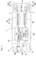
- Fig. 1 is a block diagram of a schematic configuration of an electric vehicle, as viewed from the top, that is a vehicle equipped with a drive control device according to this embodiment.
- the electric vehicle is a four-wheel vehicle or an automobile.
- the electric vehicle includes a vehicle body 1, in which left and right rear wheels are drive wheels 2, 2 and left and right front wheels are driven wheels 3, 3.
- the front wheels 3, 3 are steered wheels.
- the left and right front wheels 3, 3 can be turned via a turning mechanism not shown, and are steered through a steering device 15 such as a steering wheel.
- the left and right drive wheels 2, 2 are driven by respective independent traction motors 6, 6.
- Each motor 6 constitutes an in-wheel motor drive device IWM described below.
- Each of the wheels 2, 3 is provided with a brake not shown.
- Fig. 2 is a cross-sectional view of the in-wheel motor drive device IWM in the electric vehicle.
- Each in-wheel motor drive device IWM includes the motor 6, a speed reducer 7, and a wheel bearing 4, and some of or all of them are disposed in the wheel. Rotation of the motor 6 is transmitted to the drive wheel 2 via the speed reducer 7 and the wheel bearing 4.
- a brake rotor 5 constituting the brake is fixed to a flange portion of a hub ring 4a of the wheel bearing 4.
- the brake rotor 5 is rotated together with the drive wheel 2.
- the motor 6 is, for example, an interior permanent magnet synchronous motor in which a permanent magnet is embedded in a core portion of a rotor 6a.
- the motor 6 includes a stator 6b fixed to a housing 8 and the rotor 6a mounted to a rotational output shaft 9, between which a radial gap is formed.
- the vehicle body 1 is equipped with a drive control device 20.
- the drive control device 20 includes an ECU 21 and a plurality (two in this example) of inverter devices 22.
- the two inverter devices 22 are physically separate from each other so as to have a separate structure, and are mounted on the vehicle body 1. These inverter devices 22 are associated with the respective motors 6.
- the ECU 21 is a high-level control means configured to perform general integrated control of the automobile and to provide each inverter device 22 with a command.
- Each inverter device 22 performs control of the corresponding traction motor 6 in accordance with the command from the ECU 21.
- the ECU 21 is implemented by a computer, a program executed by the computer, various electronic circuits, and the like.
- the ECU 21 includes a command torque calculation module 47 and a torque allocation module 48.
- the command torque calculation module 47 Mainly from a signal that indicates an accelerator position and that is outputted through an accelerator manipulation device 16 and from a deceleration command outputted through a brake manipulation device 17, the command torque calculation module 47 generates, as command torques, acceleration/deceleration commands to be supplied to the traction motors 6, 6 for the left and right drive wheels 2, 2.
- the torque allocation module 48 outputs the acceleration/deceleration command values calculated by the command torque calculation module 47 to the respective inverter devices 22 so as to allocate the values to the traction motors 6, 6 for the left and right wheels 2, 2, considering a turning command outputted by a steering angle sensor that is not shown and that detects the steering angle of the steering device 15.
- the command torque calculation module 47 has a function to, when the deceleration commands are outputted thereto through the brake manipulation device 17, allocate the deceleration commands as: braking torque command values for causing the motors 6 to function as regenerative brakes; and braking torque command values for the brakes not shown.
- the braking torque command values for causing the motors 6 to function as regenerative brakes are reflected in command torque values of the acceleration/deceleration commands to be supplied to the respective traction motors 6, 6.
- the accelerator manipulation device 16 and the brake manipulation device 17 respectively include an accelerator pedal and a brake pedal, and respectively include an acceleration sensor 16a and a brake sensor 17a for detecting the amounts of operations of the respective pedals.
- a battery 19 is mounted to the vehicle body 1, and is used as a power supply for driving the motors 6 and for an electrical system of the entire vehicle.
- Fig. 3 is a block diagram of the control system of the drive control device.
- Each inverter device 22 includes: a power circuit unit 28 provided for the corresponding motor 6; and a motor control module 29 for controlling the power circuit unit 28.
- the motor control module 29 holds various kinds of information, about the corresponding in-wheel motor drive device IWM, such as detected values and/or control values (e.g., control torque, motor rotation speed, and/or other control information). These kinds of information are outputted to the ECU 21.
- the power circuit unit 28 includes an inverter 31 and a PWM driver 32 for driving the inverter 31.
- the inverter 31 converts DC power of the battery 19 ( Fig. 1 ) to three-phase AC power used for driving the motor 6.
- the inverter 31 includes a plurality of semiconductor switching elements not shown, and the PWM driver 32 drives the inverter 31 by an on/off command.
- Each semiconductor switching element is implemented by an insulated-gate bipolar transistor (IGBT), for example.
- the motor control module 29 includes: a motor drive control module 30, which serves as the basis for a control module; and a rotation speed detection module 34, which detects the rotation speed of the corresponding motor 6.
- the motor drive control module 30 converts, into a current command, the acceleration/deceleration command value that is a command torque and that has been supplied from the ECU 21, and obtains, from a current sensor 38, a motor current flowing from the inverter 31 to the motor 6, thereby performing current feedback control (control based on a control signal).
- the motor control module 29 calculates a voltage command through the current feedback control and supplies the voltage command to the PWM driver 32.
- the PWM driver 32 performs pulse width modulation of the voltage command, to supply the on/off command to semiconductor switching elements of the corresponding inverter 31.
- the rotation speed detection module 34 obtains a rotation angle of the rotor 6a ( Fig. 2 ) of the motor 6 from a rotation angle sensor 33, and calculates a rotation speed of the motor 6 by means of, for example, differentiation of the rotation angle or a state assumption observer, etc., based on physical equations, etc.
- a rotation angle sensor 33 for example, a resolver or the like is used.
- the rotation speeds of the left and right motors 6, 6 detected by the left and right rotation speed detection modules 34, 34 associated with the respective left and right motors 6, 6 are used for determination as to overrevolution, in the overrevolution prevention control module 35.
- the overrevolution prevention control module 35 is provided in the torque allocation module 48 of the ECU 21.
- the overrevolution prevention control module 35 includes a determination module 35a and a command torque change control module 35b.
- the determination module 35a constantly determines whether or not at least one rotation speed between the rotation speeds of the left and right motors 6, 6 detected by the left and right rotation speed detection modules 34, 34 has exceeded a predetermined rotation speed.
- the predetermined rotation speed is any rotation speed determined through designing, etc., and is determined by obtaining an appropriate rotation speed through, for example, a test and/or a simulation.
- the predetermined rotation speed is about 8000 rpm, for example, but is not limited to this rotation speed.
- the command torque change control module 35b changes the command torques for the left and right motors 6, 6 so as to reduce the rotation speeds of the left and right motors 6, 6 when the determination module 35a determines that at least one rotation speed between the rotation speeds of the left and right motors 6, 6 has exceeded the predetermined rotation speed. Specifically, the command torque change control module 35b performs control in which the command torques for the left and right motors 6, 6 are reduced with elapse of time, during a period in which at least one rotation speed between the rotation speeds of the left and right motors 6, 6 is higher than the predetermined rotation speed.
- the command torque change control module 35b performs control in which the command torques for the left and right motors 6, 6 are increased with elapse of time such that the command torques are restored, that is, the command torques are returned to the desired command torques.
- the desired command torques are command torques, for the respective left and right motors 6, 6, that are generated by the command torque calculation module 47 and allocated to the respective motors 6 and that are the command torques having not yet been changed by the overrevolution prevention control module 35 (just before the change).
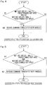
- Fig. 4 is a flowchart indicating a determination process in the overrevolution prevention control by the drive control device.
- this process is started under, for example, a condition that a main power supply of the vehicle is turned on, and the determination module 35a of the overrevolution prevention control module 35 determines whether or not the motor rotation speed of the left wheel has exceeded the predetermined rotation speed and whether or not the motor rotation speed of the right wheel has exceeded the predetermined rotation speed (step al).
- the determination as to these left and right wheels at a time when the motor rotation speed of one of the wheels is determined to have exceeded the predetermined rotation speed, the determination as to the other wheel may be omitted.
- Fig. 5 is a flowchart indicating a restoration process in the overrevolution prevention control by the drive control device.
- the determination module 35a determines whether or not the motor rotation speed of the left wheel is equal to or lower than the predetermined rotation speed and the motor rotation speed of the right wheel is equal to or lower than the predetermined rotation speed (step b1).
- the command torque change control module 35b gradually increases the command torques for the left and right motors 6, 6 (step b2). Thereafter, this process is ended.
- Fig. 6 shows diagrams indicating the relationship between motor rotation speed and motor command torque during the overrevolution prevention control. This drawing will be described with reference to Fig. 3 .
- the command torques in the example in Fig. 6 are command torques according to power running control in which driving torques in a vehicle frontward travelling direction are applied to the respective wheels.
- the command torque change control module 35b gradually reduces the command torques for the left and right motors 6, 6 from the time point T1.
- the rotation speed of the right motor 6 does not exceed the predetermined rotation speed at the time point T1 in this example.
- the degrees of reduction in the command torques are approximately equal to each other between the command torques for the left and right motors 6, 6.
- the command torque change control module 35b gradually reduces the command torques for the left and right motors 6, 6 such that the command torques linearly decrease with elapse of time. Even though the rotation speed of the right motor 6 has not exceeded the predetermined rotation speed, the command torque is gradually reduced similarly to the case of the left motor 6.
- the command torque change control module 35b gradually increases, from the time point T2, the command torques for the left and right motors 6, 6 such that the command torques are returned to command torques that have not been changed.
- the degrees of increase in the command torques are approximately equal to each other between the command torques for the left and right motors 6, 6.
- the command torque change control module 35b gradually increases the command torques for the left and right motors 6, 6 such that the command torques linearly increase with elapse of time, thereby returning the command torques to the respective command torques that have not been changed (desired command torques).
- the overrevolution prevention control module 35 increases the command torques for the left and right motors 6, 6 such that the command torques are returned to the desired command torques. In this case, the torques of the left and right drive wheels 2, 2 are restored at the same time, and thus, unexpected yaw moment can be prevented from being generated on the vehicle, which can keep the vehicle stable.
- a second embodiment will be described. Except for control by the command torque change control module 35b described below, the other features of a drive control device according to this embodiment are the same as those of the drive control device according to the first embodiment.
- the command torque change control module 35b of the overrevolution prevention control module 35 may perform adjustment control in which the command torques for the left and right motors 6, 6 are gradually reduced to be eventually reduced to zero. In this case, increase in the rotation speeds of the left and right motors 6, 6 can be reliably and easily suppressed.
- the command torque change control module 35b of the overrevolution prevention control module 35 maintains the command torques for the left and right motors 6, 6 at "zero", and, when the determination module 35a determines that both rotation speeds of the left and right motors 6, 6 are equal to or lower than the predetermined rotation speed at the time point T2, gradually increases the command torques for the left and right motors 6, 6 such that the command torques are returned to the command torques that have not been changed (desired command torques).
- a third embodiment will be described. Except for control by the command torque change control module 35b described below, the other features of a drive control device according to this embodiment are the same as those of the drive control devices according to the first and second embodiments.
- the command torque change control module 35b of the overrevolution prevention control module 35 may perform control in which the command torques for the left and right motors 6, 6 are gradually reduced, and, in a case where at least one of the rotation speeds is higher than the predetermined rotation speed even after the command torques become "zero", regenerative torques are applied to the left and right motors 6, 6.
- the control in which the regenerative torques are applied to the left and right motors 6, 6 is thus performed, the rotation speeds of the left and right motors 6, 6 can be more certainly reduced.
- the command torque change control module 35b of the overrevolution prevention control module 35 gradually increases the command torques for the left and right motors 6, 6 such that the command torques are returned to the command torques that have not been changed (desired command torques).
- a configuration may be employed in which, for the left and right motors 6, 6, a single inverter device 22A is mounted on the vehicle body 1 ( Fig. 1 ).
- the inverter device 22A in this example includes a single motor control module 29 and two power circuit units 28, 28 corresponding to the respective motors 6.
- the overrevolution prevention control module 35 is provided to the torque allocation module 48 of the ECU 21.
- the overrevolution prevention control module 35 is provided to the motor control module 29 of the inverter device 22A.
- the other components are the same as described above and the same advantageous effects are achieved.
- the vehicle may be a two-wheel independent drive vehicle, which drives two left and right front wheels independently of each other.
- the vehicle may be a four-wheel independent drive vehicle, which drives two left and right front wheels independently of each other and drives two left and right rear wheels independently of each other.
- the in-wheel motor drive device may include a cycloidal speed reducer, a planetary speed reducer, a speed reducer with two parallel shafts, or another speed reducer.
- the in-wheel motor drive device may be of a so-called direct motor type in which no speed reducer is used.
- the overrevolution prevention control module may gradually reduce the command torques for the left and right motors such that the command torques drop with elapse of time so as to, for example, form a curve in a shape of a predetermined quadratic curve.
- the overrevolution prevention control module may gradually reduce both command torques so as to combine the shape of the quadratic curve and a linear shape.
- the overrevolution prevention control module may increase the command torques such that the command torques increase so as to, for example, form a curve in a shape of a predetermined quadratic curve.
- the overrevolution prevention control module may gradually increase both command torques so as to combine the shape of the quadratic curve and a linear shape.
Landscapes
- Engineering & Computer Science (AREA)
- Transportation (AREA)
- Mechanical Engineering (AREA)
- Power Engineering (AREA)
- Life Sciences & Earth Sciences (AREA)
- Sustainable Development (AREA)
- Sustainable Energy (AREA)
- Automation & Control Theory (AREA)
- Chemical & Material Sciences (AREA)
- Combustion & Propulsion (AREA)
- Electric Propulsion And Braking For Vehicles (AREA)
Abstract
Description
- This application is based on and claims Convention priority to Japanese patent application No.
2016-024414, filed February 12, 2016 - The present invention relates to a drive control device for a vehicle with independently driven wheels, and more specifically, relates to a technique which allows a vehicle to avoid unstable behavior caused by an overrevolution of one of a pair of left and right drive wheels.
- The following techniques have been proposed in order to perform control for preventing an overrevolution of a traction motor in an electric vehicle.
- 1. Technique in which coasting or regeneration is performed when the rotation speed of a motor is not less than a predetermined value (Patent Document 1).
- 2. Technique in which a drive command for a motor is stopped and a power generation command is sent instead, when the rotation speed of the motor exceeds a maximum rotation rate (Patent Document 2).
- 3. Technique in which a torque command value is set to zero when the rotation speed of a motor exceeds a first predetermined value, and the torque command value is restored when the rotation speed of the motor becomes not greater than a second predetermined value, and in which the torque is gradually reduced by a delay process while the rotation speed of the motor is between the first and second predetermined values, when the torque command value is set to zero (Patent Document 3).
- In a case where an overrevolution of an engine is prevented, increase in the rotation speed is suppressed by stopping ignition or fuel injection, or reducing the number of times of ignition or fuel injection when a predetermined rotation speed is exceeded. On the other hand, in order to prevent an overspeed of a motor, increase in the rotation speed is suppressed by reducing a command torque to the motor such that the command torque becomes zero or a regenerative torque is applied.
-
- [Patent Document 1]
JP Laid-open Patent Publication No. H08-163702 - [Patent Document 2]
JP Laid-open Patent Publication No. H08-223704 - [Patent Document 3]
JP Laid-open Patent Publication No. H10-248107 - However, in a vehicle that drives left and right wheels independently of each other, a difference in rotation speed between the left and right wheels can be generated. For example, while such a vehicle is turning, a difference in rotation speed between the inner wheel and the outer wheel is generated owing to a difference therebetween in the turning radius. In addition, such a difference in rotation speed is generated owing to also a difference of the diameters of tires due to a difference in wear or pneumatic pressure between the tires. Thus, the rotation speeds of the left and right wheels are often not equal to each other. In the vehicle that drives the left and right wheels independently of each other, when overrevolution prevention control is individually performed on the rotation speeds of motors, in only one of the wheels, torque may drop or be released, or regenerative braking may be caused, and thereafter, the torque may be restored. Accordingly, unexpected yaw moment can be generated on the vehicle, which causes the vehicle to behave unstably.
- Patent Documents 1 to 3 each disclose a technique in which the torque command is made zero or the regenerative torque is applied. However, in each of Patent Documents 1 to 3, a single motor is used, and a case is not assumed where left and right wheels are driven independently of each other by separate motors. If the techniques of Patent Documents 1 to 3 are applied to a vehicle including left and right motors for individually driving left and right drive wheels, unexpected yaw moment is generated on the vehicle owing to such a difference in rotation speed between the left and right wheels as aforementioned, and the vehicle may behave unstably.
- An object of the present invention is to provide a drive control device for a vehicle with independently driven wheels, the drive control device enabling the vehicle to avoid unstable behavior caused by an overrevolution of one of the drive wheels.
- Hereinafter, for convenience of easy understanding, a description will be given with reference to the reference numerals in embodiments.
- A drive control device for a vehicle with independently driven wheels according to one aspect of the present invention, the vehicle being equipped with the drive control device, the vehicle including left and
right motors right drive wheels - an ECU 21 configured to generate and output a command torque;
- an inverter device 22 (22A) having a
power circuit unit 28 and amotor control module 29, thepower circuit unit 28 including aninverter 31 configured to convert DC power into AC power, themotor control module 29 being configured to perform torque control of themotor 6 via thepower circuit unit 28 in accordance with the command torque supplied from the ECU 21; - left and right rotation
speed detection modules right motors - an overrevolution
prevention control module 35 configured to change the command torques for the respective left andright motors right motors right motors speed detection modules - The predetermined rotation speed is any rotation speed determined through designing, etc., and is determined by obtaining an appropriate rotation speed through, for example, a test and/or a simulation.
- In this specification, the "rotation speed" is synonymous with the number of revolution per unit time.
- In this configuration, the left and right rotation
speed detection modules right motors prevention control module 35 determines whether or not at least one of the detected rotation speeds of the respective left andright motors prevention control module 35 changes the command torque for the respective left andright motors right motors - Conventionally, overrevolution prevention control is performed on the left and right motors in accordance with the respective rotation speeds, and thus, the torque of only a motor having the higher rotation speed drops or is released, which can generate unexpected yaw moment on the vehicle and cause the vehicle to behave unstably.
- On the other hand, in this configuration, when for example a motor rotation speed which is the higher between the rotation speeds of the left and
right motors right motors right motors right drive wheels - The rotation speed detection module may be included in the inverter. The overrevolution prevention control module may be included in the ECU or the inverter device.
- The overrevolution
prevention control module 35 may perform control in which the command torques for the respective left andright motors right motors right motors - The overrevolution
prevention control module 35 may perform control in which the command torques for the respective left andright motors - The overrevolution
prevention control module 35 may perform control in which the command torques for the respective left andright motors right motors right motors right motors - The overrevolution
prevention control module 35 may increase the command torques for the respective left andright motors right motors speed detection modules - The desired command torques are the command torques having not yet been changed by the overrevolution prevention control module 35 (just before the change), for the respective left and
right motors right motors right motors - In this configuration, the torques of the left and
right drive wheels - The overrevolution prevention control module may change the command torques for the respective left and right motors by approximately equal degrees with elapse of time.
- Any combination of at least two constructions, disclosed in the appended claims and/or the specification and/or the accompanying drawings should be construed as included within the scope of the present invention. In particular, any combination of two or more of the appended claims should be equally construed as included within the scope of the present invention.
- In any event, the present invention will become more clearly understood from the following description of preferred embodiments thereof, when taken in conjunction with the accompanying drawings. However, the embodiments and the drawings are given only for the purpose of illustration and explanation, and are not to be taken as limiting the scope of the present invention in any way whatsoever, which scope is to be determined by the appended claims. In the accompanying drawings, like reference numerals are used to denote like parts throughout the several views, and:
-
Fig. 1 is a block diagram of a schematic configuration of an electric vehicle, as viewed from the top, that is equipped with a drive control device according to a first embodiment of the present invention; -
Fig. 2 is a cross-sectional view of an in-wheel motor drive device in the electric vehicle inFig. 1 ; -
Fig. 3 is a block diagram of a control system of the drive control device inFig. 1 ; -
Fig. 4 is a flowchart indicating a determination process in overrevolution prevention control by the drive control device inFig. 1 ; -
Fig. 5 is a flowchart indicating a restoration process in the overrevolution prevention control by the drive control device inFig. 1 ; -
Fig. 6 shows diagrams indicating the relationship between motor rotation speed and motor command torque during the overrevolution prevention control by the drive control device inFig. 1 ; -
Fig. 7 shows diagrams indicating the relationship between motor rotation speed and motor command torque during overrevolution prevention control by a drive control device according to a second embodiment of the present invention; -
Fig. 8 shows diagrams indicating the relationship between motor rotation speed and motor command torque during overrevolution prevention control by a drive control device according to a third embodiment of the present invention; and -
Fig. 9 is a block diagram of a control system of a drive control device according to a fourth embodiment of the present invention. - A first embodiment of the present invention will be described with reference to
Fig. 1 to Fig. 6 . -
Fig. 1 is a block diagram of a schematic configuration of an electric vehicle, as viewed from the top, that is a vehicle equipped with a drive control device according to this embodiment. The electric vehicle is a four-wheel vehicle or an automobile. The electric vehicle includes a vehicle body 1, in which left and right rear wheels aredrive wheels wheels front wheels front wheels steering device 15 such as a steering wheel. The left andright drive wheels independent traction motors motor 6 constitutes an in-wheel motor drive device IWM described below. Each of thewheels -
Fig. 2 is a cross-sectional view of the in-wheel motor drive device IWM in the electric vehicle. Each in-wheel motor drive device IWM includes themotor 6, aspeed reducer 7, and awheel bearing 4, and some of or all of them are disposed in the wheel. Rotation of themotor 6 is transmitted to thedrive wheel 2 via thespeed reducer 7 and thewheel bearing 4. Abrake rotor 5 constituting the brake is fixed to a flange portion of ahub ring 4a of thewheel bearing 4. Thebrake rotor 5 is rotated together with thedrive wheel 2. Themotor 6 is, for example, an interior permanent magnet synchronous motor in which a permanent magnet is embedded in a core portion of a rotor 6a. Themotor 6 includes astator 6b fixed to ahousing 8 and the rotor 6a mounted to arotational output shaft 9, between which a radial gap is formed. - A control system will be described.
- As shown in
Fig. 1 , the vehicle body 1 is equipped with adrive control device 20. Thedrive control device 20 includes anECU 21 and a plurality (two in this example) ofinverter devices 22. In this embodiment, the twoinverter devices 22 are physically separate from each other so as to have a separate structure, and are mounted on the vehicle body 1. Theseinverter devices 22 are associated with therespective motors 6. TheECU 21 is a high-level control means configured to perform general integrated control of the automobile and to provide eachinverter device 22 with a command. Eachinverter device 22 performs control of thecorresponding traction motor 6 in accordance with the command from theECU 21. TheECU 21 is implemented by a computer, a program executed by the computer, various electronic circuits, and the like. - The
ECU 21 includes a commandtorque calculation module 47 and atorque allocation module 48. Mainly from a signal that indicates an accelerator position and that is outputted through anaccelerator manipulation device 16 and from a deceleration command outputted through abrake manipulation device 17, the commandtorque calculation module 47 generates, as command torques, acceleration/deceleration commands to be supplied to thetraction motors right drive wheels torque allocation module 48 outputs the acceleration/deceleration command values calculated by the commandtorque calculation module 47 to therespective inverter devices 22 so as to allocate the values to thetraction motors right wheels steering device 15. - In addition, the command
torque calculation module 47 has a function to, when the deceleration commands are outputted thereto through thebrake manipulation device 17, allocate the deceleration commands as: braking torque command values for causing themotors 6 to function as regenerative brakes; and braking torque command values for the brakes not shown. The braking torque command values for causing themotors 6 to function as regenerative brakes are reflected in command torque values of the acceleration/deceleration commands to be supplied to therespective traction motors accelerator manipulation device 16 and thebrake manipulation device 17 respectively include an accelerator pedal and a brake pedal, and respectively include anacceleration sensor 16a and abrake sensor 17a for detecting the amounts of operations of the respective pedals. Abattery 19 is mounted to the vehicle body 1, and is used as a power supply for driving themotors 6 and for an electrical system of the entire vehicle. -
Fig. 3 is a block diagram of the control system of the drive control device. - Each
inverter device 22 includes: apower circuit unit 28 provided for thecorresponding motor 6; and amotor control module 29 for controlling thepower circuit unit 28. Themotor control module 29 holds various kinds of information, about the corresponding in-wheel motor drive device IWM, such as detected values and/or control values (e.g., control torque, motor rotation speed, and/or other control information). These kinds of information are outputted to theECU 21. - The
power circuit unit 28 includes aninverter 31 and aPWM driver 32 for driving theinverter 31. Theinverter 31 converts DC power of the battery 19 (Fig. 1 ) to three-phase AC power used for driving themotor 6. Theinverter 31 includes a plurality of semiconductor switching elements not shown, and thePWM driver 32 drives theinverter 31 by an on/off command. Each semiconductor switching element is implemented by an insulated-gate bipolar transistor (IGBT), for example. - The
motor control module 29 includes: a motordrive control module 30, which serves as the basis for a control module; and a rotationspeed detection module 34, which detects the rotation speed of thecorresponding motor 6. The motordrive control module 30 converts, into a current command, the acceleration/deceleration command value that is a command torque and that has been supplied from theECU 21, and obtains, from acurrent sensor 38, a motor current flowing from theinverter 31 to themotor 6, thereby performing current feedback control (control based on a control signal). Themotor control module 29 calculates a voltage command through the current feedback control and supplies the voltage command to thePWM driver 32. ThePWM driver 32 performs pulse width modulation of the voltage command, to supply the on/off command to semiconductor switching elements of the correspondinginverter 31. - The rotation
speed detection module 34 obtains a rotation angle of the rotor 6a (Fig. 2 ) of themotor 6 from arotation angle sensor 33, and calculates a rotation speed of themotor 6 by means of, for example, differentiation of the rotation angle or a state assumption observer, etc., based on physical equations, etc. As therotation angle sensor 33, for example, a resolver or the like is used. The rotation speeds of the left andright motors speed detection modules right motors prevention control module 35. - In this embodiment, the overrevolution
prevention control module 35 is provided in thetorque allocation module 48 of theECU 21. The overrevolutionprevention control module 35 includes adetermination module 35a and a command torquechange control module 35b. Thedetermination module 35a constantly determines whether or not at least one rotation speed between the rotation speeds of the left andright motors speed detection modules - The command torque
change control module 35b changes the command torques for the left andright motors right motors determination module 35a determines that at least one rotation speed between the rotation speeds of the left andright motors change control module 35b performs control in which the command torques for the left andright motors right motors - When the
determination module 35a determines that both rotation speeds of the left andright motors change control module 35b performs control in which the command torques for the left andright motors right motors torque calculation module 47 and allocated to therespective motors 6 and that are the command torques having not yet been changed by the overrevolution prevention control module 35 (just before the change). -
Fig. 4 is a flowchart indicating a determination process in the overrevolution prevention control by the drive control device. With reference toFig. 3 andFig. 4 , this process is started under, for example, a condition that a main power supply of the vehicle is turned on, and thedetermination module 35a of the overrevolutionprevention control module 35 determines whether or not the motor rotation speed of the left wheel has exceeded the predetermined rotation speed and whether or not the motor rotation speed of the right wheel has exceeded the predetermined rotation speed (step al). Regarding the determination as to these left and right wheels, at a time when the motor rotation speed of one of the wheels is determined to have exceeded the predetermined rotation speed, the determination as to the other wheel may be omitted. When neither of the motor rotation speeds of the left wheel and the right wheel is determined to have exceeded the predetermined rotation speed (No in step a1), this process is ended. When at least one of the rotation speeds is determined to have exceeded the predetermined rotation speed (Yes in step a1), the command torquechange control module 35b of the overrevolutionprevention control module 35 gradually reduces the command torques for the left andright motors 6, 6 (step a2). Thereafter, this process is ended. -
Fig. 5 is a flowchart indicating a restoration process in the overrevolution prevention control by the drive control device. With reference toFig. 3 andFig. 5 , during execution of the aforementioned control in which the command torques are reduced, thedetermination module 35a determines whether or not the motor rotation speed of the left wheel is equal to or lower than the predetermined rotation speed and the motor rotation speed of the right wheel is equal to or lower than the predetermined rotation speed (step b1). When neither of the motor rotation speeds is determined to be equal to or lower than the predetermined rotation speed (No in step b1), this process is ended. When both motor rotation speeds are determined to be equal to or lower than the predetermined rotation speed (Yes in step b1), the command torquechange control module 35b gradually increases the command torques for the left andright motors 6, 6 (step b2). Thereafter, this process is ended. -
Fig. 6 shows diagrams indicating the relationship between motor rotation speed and motor command torque during the overrevolution prevention control. This drawing will be described with reference toFig. 3 . The command torques in the example inFig. 6 are command torques according to power running control in which driving torques in a vehicle frontward travelling direction are applied to the respective wheels. When thedetermination module 35a determines that the rotation speed of theleft motor 6 has exceeded the predetermined rotation speed at a time point T1, the command torquechange control module 35b gradually reduces the command torques for the left andright motors - The rotation speed of the
right motor 6 does not exceed the predetermined rotation speed at the time point T1 in this example. The degrees of reduction in the command torques are approximately equal to each other between the command torques for the left andright motors change control module 35b gradually reduces the command torques for the left andright motors right motor 6 has not exceeded the predetermined rotation speed, the command torque is gradually reduced similarly to the case of theleft motor 6. - Thereafter, when the
determination module 35a determines that the rotation speed of theleft motor 6 falls below the predetermined rotation speed at a time point T2, since the rotation speed of theright motor 6 is changing in a state of being equal to or lower than the predetermined rotation speed, the command torquechange control module 35b gradually increases, from the time point T2, the command torques for the left andright motors right motors change control module 35b gradually increases the command torques for the left andright motors - Effects will be described.
- According to the
drive control device 20 described above, when for example a motor rotation speed which is the higher between the rotation speeds of the left andright motors right motors right motors right motors right motors - When both rotation speeds of the left and
right motors prevention control module 35 increases the command torques for the left andright motors right drive wheels - A second embodiment will be described. Except for control by the command torque
change control module 35b described below, the other features of a drive control device according to this embodiment are the same as those of the drive control device according to the first embodiment. - With reference to
Fig. 7 andFig. 3 , when thedetermination module 35a determines that the rotation speed of theleft motor 6 has exceeded the predetermined rotation speed at the time point T1, the command torquechange control module 35b of the overrevolutionprevention control module 35 may perform adjustment control in which the command torques for the left andright motors right motors change control module 35b of the overrevolutionprevention control module 35 maintains the command torques for the left andright motors determination module 35a determines that both rotation speeds of the left andright motors right motors - A third embodiment will be described. Except for control by the command torque
change control module 35b described below, the other features of a drive control device according to this embodiment are the same as those of the drive control devices according to the first and second embodiments. - With reference to
Fig. 8 andFig. 3 , when thedetermination module 35a determines that the rotation speed of theleft motor 6 has exceeded the predetermined rotation speed at the time point T1, the command torquechange control module 35b of the overrevolutionprevention control module 35 may perform control in which the command torques for the left andright motors right motors right motors right motors determination module 35a determines that both rotation speeds of the left andright motors change control module 35b of the overrevolutionprevention control module 35 gradually increases the command torques for the left andright motors - A fourth embodiment will be described. In the following description, the components corresponding to the matters described in each of the preceding embodiments are denoted by like reference numerals, and any redundant description has been omitted. When only a part of a configuration is described, the remaining part of the configuration is the same as that of the previously described embodiments unless otherwise specified. The same advantageous effects are achieved by the same configuration. In addition to the combinations of portions described specifically in each embodiment, it is also possible to partially combine the embodiments unless any problem is particularly posed due to the combination.
- As shown in
Fig. 9 , a configuration may be employed in which, for the left andright motors single inverter device 22A is mounted on the vehicle body 1 (Fig. 1 ). Theinverter device 22A in this example includes a singlemotor control module 29 and twopower circuit units respective motors 6. In the first embodiment described with reference toFig. 3 , the overrevolutionprevention control module 35 is provided to thetorque allocation module 48 of theECU 21. However, in this embodiment, the overrevolutionprevention control module 35 is provided to themotor control module 29 of theinverter device 22A. The other components are the same as described above and the same advantageous effects are achieved. - The vehicle may be a two-wheel independent drive vehicle, which drives two left and right front wheels independently of each other. Alternatively, the vehicle may be a four-wheel independent drive vehicle, which drives two left and right front wheels independently of each other and drives two left and right rear wheels independently of each other.
- The in-wheel motor drive device may include a cycloidal speed reducer, a planetary speed reducer, a speed reducer with two parallel shafts, or another speed reducer. Alternatively, the in-wheel motor drive device may be of a so-called direct motor type in which no speed reducer is used.
- The overrevolution prevention control module may gradually reduce the command torques for the left and right motors such that the command torques drop with elapse of time so as to, for example, form a curve in a shape of a predetermined quadratic curve. Alternatively, the overrevolution prevention control module may gradually reduce both command torques so as to combine the shape of the quadratic curve and a linear shape.
- When increasing the command torques for the left and right motors with elapse of time, the overrevolution prevention control module may increase the command torques such that the command torques increase so as to, for example, form a curve in a shape of a predetermined quadratic curve. Alternatively, the overrevolution prevention control module may gradually increase both command torques so as to combine the shape of the quadratic curve and a linear shape.
- Although the modes for carrying out the present invention have been described on the basis of the embodiments, the embodiments disclosed herein are illustrative in all aspects and not restrictive. The scope of the present invention is indicated not by the above description but by the claims, and is intended to include any modifications within the scope and meaning equivalent to the claims.
-
- 2 ···· drive wheel
- 6 ···· motor
- 20 ··· drive control device
- 21 ···· ECU
- 22, 22A ···· inverter device
- 28 ····power circuit unit
- 29 ····motor control module
- 31 ····inverter
- 34 ····rotation speed detection module
- 35 ····overrevolution prevention control module
Claims (6)
- A drive control device for a vehicle, the vehicle being equipped with the drive control device, the vehicle including left and right motors that independently drive left and right drive wheels, respectively, the drive control device comprising:an ECU configured to generate and output a command torque;an inverter device having a power circuit unit and a motor control module, the power circuit including an inverter configured to convert DC power into AC power, the motor control module being configured to perform torque control of the motor via the power circuit unit in accordance with the command torque supplied from the ECU;left and right rotation speed detection modules configured to detect rotation speeds of the respective left and right motors; andan overrevolution prevention control module configured to change the command torques for the respective left and right motors so as to reduce the rotation speeds of the left and right motors when at least one of the rotation speeds of the left and right motors detected by the left and right rotation speed detection modules exceeds a predetermined rotation speed.
- The drive control device as claimed in claim 1, wherein the overrevolution prevention control module performs control in which the command torques for the respective left and right motors are reduced with elapse of time, during a period in which at least one of the rotation speeds of the left and right motors is higher than the predetermined rotation speed.
- The drive control device as claimed in claim 2, wherein the overrevolution prevention control module performs control in which the command torques for the respective left and right motors are reduced to zero.
- The drive control device as claimed in claim 2, wherein the overrevolution prevention control module performs control in which the command torques for the respective left and right motors are reduced with elapse of time, and, in a case where at least one of the rotation speeds is higher than the predetermined rotation speed even after the command torques are reduced to zero, regenerative torques are applied to the left and right motors.
- The drive control device as claimed in any one of claims 1 to 4, wherein the overrevolution prevention control module increases the command torques for the respective left and right motors such that the command torques are returned to a desired command torque, when both rotation speeds of the left and right motors detected by the left and right rotation speed detection modules become equal to or lower than the predetermined rotation speed.
- The drive control device as claimed in any one of claims 1 to 4, wherein the overrevolution prevention control module changes the command torques for the respective left and right motors by approximately equal degrees with elapse of time.
Applications Claiming Priority (2)
| Application Number | Priority Date | Filing Date | Title |
|---|---|---|---|
| JP2016024414A JP6651374B2 (en) | 2016-02-12 | 2016-02-12 | Drive control device for wheel independent drive type vehicle |
| PCT/JP2017/004650 WO2017138587A1 (en) | 2016-02-12 | 2017-02-08 | Drive control apparatus for individual-wheel drive vehicles |
Publications (2)
| Publication Number | Publication Date |
|---|---|
| EP3415360A1 true EP3415360A1 (en) | 2018-12-19 |
| EP3415360A4 EP3415360A4 (en) | 2019-08-07 |
Family
ID=59563125
Family Applications (1)
| Application Number | Title | Priority Date | Filing Date |
|---|---|---|---|
| EP17750308.3A Pending EP3415360A4 (en) | 2016-02-12 | 2017-02-08 | DRIVE CONTROL APPARATUS FOR INDIVIDUAL TRACTION VEHICLES |
Country Status (5)
| Country | Link |
|---|---|
| US (1) | US10889188B2 (en) |
| EP (1) | EP3415360A4 (en) |
| JP (1) | JP6651374B2 (en) |
| CN (1) | CN107848426B (en) |
| WO (1) | WO2017138587A1 (en) |
Families Citing this family (7)
| Publication number | Priority date | Publication date | Assignee | Title |
|---|---|---|---|---|
| US10793157B2 (en) * | 2017-05-24 | 2020-10-06 | Toyota Motor Engineering & Manufacturing North America, Inc. | Operating electrified vehicles during traction events |
| KR102334659B1 (en) * | 2017-06-29 | 2021-12-03 | 현대모비스 주식회사 | Apparatus and method for detecting faults in in-wheel driving system of vehicle |
| CN112440751A (en) * | 2020-11-06 | 2021-03-05 | 广东高标电子科技有限公司 | Electric vehicle braking energy recovery method |
| JP7596935B2 (en) * | 2021-06-01 | 2024-12-10 | トヨタ自動車株式会社 | Vehicle control device |
| CN114940157B (en) * | 2022-05-11 | 2025-03-21 | 臻驱科技(上海)股份有限公司 | A method and system for controlling motor speed of hybrid vehicle |
| FR3141634B1 (en) * | 2022-11-04 | 2026-01-16 | Aldebaran | Overspeed detection device |
| US12491776B2 (en) | 2023-02-02 | 2025-12-09 | Ford Global Technologies, Llc | Methods and system for balancing torque request during battery power control |
Family Cites Families (16)
| Publication number | Priority date | Publication date | Assignee | Title |
|---|---|---|---|---|
| US5453930A (en) * | 1991-02-08 | 1995-09-26 | Nissan Motor Co., Ltd. | Drive system for electric automobiles |
| JPH08163702A (en) | 1994-12-01 | 1996-06-21 | Matsushita Electric Ind Co Ltd | Motor control method |
| JPH08223704A (en) | 1995-02-09 | 1996-08-30 | Nissan Motor Co Ltd | Electric vehicle controller |
| JPH10248107A (en) | 1997-03-04 | 1998-09-14 | Honda Motor Co Ltd | Electric vehicle control device |
| JP3804383B2 (en) * | 2000-01-19 | 2006-08-02 | トヨタ自動車株式会社 | Control device for vehicle having fuel cell |
| US6909959B2 (en) * | 2003-03-07 | 2005-06-21 | Stephen James Hallowell | Torque distribution systems and methods for wheeled vehicles |
| US7279855B2 (en) * | 2003-04-04 | 2007-10-09 | Hitachi, Ltd. | Electric drive device for vehicle and hybrid engine/motor-type four wheel drive device |
| JP4513612B2 (en) * | 2005-03-16 | 2010-07-28 | 日産自動車株式会社 | Vehicle torque distribution control device |
| CN101351355B (en) * | 2005-12-26 | 2010-11-10 | 丰田自动车株式会社 | Vehicle controller, vehicle and vehicle control method |
| JP4685655B2 (en) * | 2006-02-15 | 2011-05-18 | トヨタ自動車株式会社 | Control device for electric vehicle |
| US8113307B2 (en) * | 2006-11-17 | 2012-02-14 | Holland Ronald A | Electric vehicle drive system |
| JP4358264B2 (en) * | 2007-08-08 | 2009-11-04 | 株式会社日本自動車部品総合研究所 | Hybrid vehicle |
| JP5840464B2 (en) * | 2011-11-11 | 2016-01-06 | Ntn株式会社 | Electric car |
| JP2015100149A (en) | 2013-11-18 | 2015-05-28 | Ntn株式会社 | Anti-loci brake controller |
| JP6250445B2 (en) * | 2014-03-19 | 2017-12-20 | Ntn株式会社 | Electric vehicle slip control device |
| JP2015192471A (en) * | 2014-03-27 | 2015-11-02 | 日産自動車株式会社 | vehicle motion control device |
-
2016
- 2016-02-12 JP JP2016024414A patent/JP6651374B2/en active Active
-
2017
- 2017-02-08 EP EP17750308.3A patent/EP3415360A4/en active Pending
- 2017-02-08 WO PCT/JP2017/004650 patent/WO2017138587A1/en not_active Ceased
- 2017-02-08 CN CN201780002395.0A patent/CN107848426B/en active Active
-
2018
- 2018-08-10 US US16/101,017 patent/US10889188B2/en active Active
Also Published As
| Publication number | Publication date |
|---|---|
| US20180345796A1 (en) | 2018-12-06 |
| CN107848426A (en) | 2018-03-27 |
| JP2017143678A (en) | 2017-08-17 |
| JP6651374B2 (en) | 2020-02-19 |
| EP3415360A4 (en) | 2019-08-07 |
| WO2017138587A1 (en) | 2017-08-17 |
| US10889188B2 (en) | 2021-01-12 |
| WO2017138587A8 (en) | 2018-08-09 |
| CN107848426B (en) | 2021-11-30 |
Similar Documents
| Publication | Publication Date | Title |
|---|---|---|
| US10889188B2 (en) | Drive control device for vehicle with independently driven wheels | |
| EP3190000B1 (en) | Electronic stability control system for vehicle | |
| CN107054354B (en) | The driving-force control apparatus of vehicle | |
| JP5985178B2 (en) | Motor control device | |
| US9827874B2 (en) | Vehicle | |
| JP5705585B2 (en) | Electric car | |
| JP5381954B2 (en) | Vehicle driving force control device | |
| EP3072730A1 (en) | Antilock brake control device | |
| JP6534509B2 (en) | Drive control device for a wheel independent drive type vehicle | |
| US10017075B2 (en) | Device for controlling electric automobile | |
| JP6396180B2 (en) | Drive control device for wheel independent drive type vehicle | |
| US20150191089A1 (en) | Electric vehicle and control method | |
| JP6411132B2 (en) | Drive control device for wheel independent drive type vehicle | |
| WO2016125686A1 (en) | Vehicle braking/driving torque control device | |
| EP2818354A1 (en) | Drive control device for vehicle | |
| WO2021182428A1 (en) | Drive control device for vehicle having independently driven wheels | |
| JP6199454B2 (en) | Motor control device | |
| WO2017018335A1 (en) | Motor drive device | |
| JP2013251988A (en) | Motor generator control device | |
| JP6137045B2 (en) | Vehicle drive motor control device | |
| WO2021125218A1 (en) | Drive control apparatus and drive control method for vehicle having independently driven wheels | |
| US20190291592A1 (en) | Vehicle control device | |
| JP6443266B2 (en) | VEHICLE CONTROL METHOD AND VEHICLE CONTROL DEVICE | |
| JP2025098471A (en) | Electric vehicle control device |
Legal Events
| Date | Code | Title | Description |
|---|---|---|---|
| STAA | Information on the status of an ep patent application or granted ep patent |
Free format text: STATUS: THE INTERNATIONAL PUBLICATION HAS BEEN MADE |
|
| PUAI | Public reference made under article 153(3) epc to a published international application that has entered the european phase |
Free format text: ORIGINAL CODE: 0009012 |
|
| STAA | Information on the status of an ep patent application or granted ep patent |
Free format text: STATUS: REQUEST FOR EXAMINATION WAS MADE |
|
| 17P | Request for examination filed |
Effective date: 20180904 |
|
| AK | Designated contracting states |
Kind code of ref document: A1 Designated state(s): AL AT BE BG CH CY CZ DE DK EE ES FI FR GB GR HR HU IE IS IT LI LT LU LV MC MK MT NL NO PL PT RO RS SE SI SK SM TR |
|
| AX | Request for extension of the european patent |
Extension state: BA ME |
|
| DAV | Request for validation of the european patent (deleted) | ||
| DAX | Request for extension of the european patent (deleted) | ||
| A4 | Supplementary search report drawn up and despatched |
Effective date: 20190709 |
|
| RIC1 | Information provided on ipc code assigned before grant |
Ipc: B60L 3/10 20060101ALI20190703BHEP Ipc: B60T 8/175 20060101ALI20190703BHEP Ipc: B60L 7/22 20060101ALI20190703BHEP Ipc: B60L 9/18 20060101AFI20190703BHEP Ipc: B60L 7/10 20060101ALI20190703BHEP Ipc: B60L 15/20 20060101ALI20190703BHEP Ipc: B60K 1/02 20060101ALI20190703BHEP Ipc: B60L 3/00 20190101ALI20190703BHEP Ipc: B60K 28/16 20060101ALI20190703BHEP Ipc: B60W 30/18 20120101ALI20190703BHEP |
|
| STAA | Information on the status of an ep patent application or granted ep patent |
Free format text: STATUS: EXAMINATION IS IN PROGRESS |
|
| 17Q | First examination report despatched |
Effective date: 20210408 |