EP3415252B1 - Caster tip arrangement for a continuous caster - Google Patents
Caster tip arrangement for a continuous caster Download PDFInfo
- Publication number
- EP3415252B1 EP3415252B1 EP17176119.0A EP17176119A EP3415252B1 EP 3415252 B1 EP3415252 B1 EP 3415252B1 EP 17176119 A EP17176119 A EP 17176119A EP 3415252 B1 EP3415252 B1 EP 3415252B1
- Authority
- EP
- European Patent Office
- Prior art keywords
- caster
- tip arrangement
- boundary region
- lateral boundary
- melt
- Prior art date
- Legal status (The legal status is an assumption and is not a legal conclusion. Google has not performed a legal analysis and makes no representation as to the accuracy of the status listed.)
- Active
Links
Images


Classifications
-
- B—PERFORMING OPERATIONS; TRANSPORTING
- B22—CASTING; POWDER METALLURGY
- B22D—CASTING OF METALS; CASTING OF OTHER SUBSTANCES BY THE SAME PROCESSES OR DEVICES
- B22D11/00—Continuous casting of metals, i.e. casting in indefinite lengths
- B22D11/06—Continuous casting of metals, i.e. casting in indefinite lengths into moulds with travelling walls, e.g. with rolls, plates, belts, caterpillars
- B22D11/0637—Accessories therefor
- B22D11/064—Accessories therefor for supplying molten metal
- B22D11/0642—Nozzles
-
- B—PERFORMING OPERATIONS; TRANSPORTING
- B22—CASTING; POWDER METALLURGY
- B22D—CASTING OF METALS; CASTING OF OTHER SUBSTANCES BY THE SAME PROCESSES OR DEVICES
- B22D11/00—Continuous casting of metals, i.e. casting in indefinite lengths
- B22D11/06—Continuous casting of metals, i.e. casting in indefinite lengths into moulds with travelling walls, e.g. with rolls, plates, belts, caterpillars
- B22D11/0628—Continuous casting of metals, i.e. casting in indefinite lengths into moulds with travelling walls, e.g. with rolls, plates, belts, caterpillars formed by more than two casting wheels
-
- B—PERFORMING OPERATIONS; TRANSPORTING
- B22—CASTING; POWDER METALLURGY
- B22D—CASTING OF METALS; CASTING OF OTHER SUBSTANCES BY THE SAME PROCESSES OR DEVICES
- B22D11/00—Continuous casting of metals, i.e. casting in indefinite lengths
- B22D11/06—Continuous casting of metals, i.e. casting in indefinite lengths into moulds with travelling walls, e.g. with rolls, plates, belts, caterpillars
- B22D11/0637—Accessories therefor
- B22D11/064—Accessories therefor for supplying molten metal
-
- B—PERFORMING OPERATIONS; TRANSPORTING
- B22—CASTING; POWDER METALLURGY
- B22D—CASTING OF METALS; CASTING OF OTHER SUBSTANCES BY THE SAME PROCESSES OR DEVICES
- B22D11/00—Continuous casting of metals, i.e. casting in indefinite lengths
- B22D11/06—Continuous casting of metals, i.e. casting in indefinite lengths into moulds with travelling walls, e.g. with rolls, plates, belts, caterpillars
- B22D11/0605—Continuous casting of metals, i.e. casting in indefinite lengths into moulds with travelling walls, e.g. with rolls, plates, belts, caterpillars formed by two belts, e.g. Hazelett-process
-
- B—PERFORMING OPERATIONS; TRANSPORTING
- B22—CASTING; POWDER METALLURGY
- B22D—CASTING OF METALS; CASTING OF OTHER SUBSTANCES BY THE SAME PROCESSES OR DEVICES
- B22D11/00—Continuous casting of metals, i.e. casting in indefinite lengths
- B22D11/06—Continuous casting of metals, i.e. casting in indefinite lengths into moulds with travelling walls, e.g. with rolls, plates, belts, caterpillars
- B22D11/0622—Continuous casting of metals, i.e. casting in indefinite lengths into moulds with travelling walls, e.g. with rolls, plates, belts, caterpillars formed by two casting wheels
Definitions
- the invention relates to casting an object from a melt comprising molten metal and/or to casting of molten metal into a solidified object, such as e.g. a sheet, a plate, a bar, an ingot, a strip or the like.
- a solidified object such as e.g. a sheet, a plate, a bar, an ingot, a strip or the like.
- the invention relates to a caster tip arrangement for a continuous caster, a use of such caster tip arrangement in a continuous caster, a continuous caster with such caster tip arrangement, and a method for operating a continuous caster comprising such caster tip arrangement.
- An exemplary casting method is the so-called strip casting and/or continuous casting using a continuous caster and/or a continuous caster device, such as e.g. a block caster, a twin-roll caster and/or a twin-belt caster.
- a material comprising metal and/or an alloy is molten, e.g. by means of a melting furnace, and then supplied to a moving casting mold of the continuous caster, which may comprise e.g. a block chain arrangement with at least one moving block chain, a roll arrangement with at least one roll and/or a belt arrangement with at least one belt, for forming a metal strip.
- a nozzle system and/or a caster tip arrangement is used, wherein the caster tip arrangement comprises an outlet for discharging the melt and guiding the melt to the moving casting mold.
- the melt is then solidified and a continuous strip and/or metal band may be formed.
- Document US 2017/0106435 A1 relates to a caster tip for a twin roll continuous strip caster for non-ferrous metals.
- the caster tip includes a caster tip body made primarily of ceramic material, and an electric resistance heater thermally connected to the caster tip body for pre-heating the caster tip body to a predetermined temperature before a melt is introduced into the caster tip.
- Document US 5 435 375 A relates to a titanium composite casting nozzle for a continuous caster.
- the casting nozzle is designed for transferring molten metal from a molten reservoir to a continuously advancing mold for casting the molten metal.
- the nozzle comprises a top wall, a bottom wall and two side walls forming a passage therebetween.
- the nozzle is fabricated from a composite material comprised of a base layer of a titanium alloy and a refractory layer bonded to the base layer. Via resistive heating, the nozzle can be pre-heated before a melt is inserted into the nozzle.
- a first aspect of the invention relates to a caster tip arrangement for a continuous caster for casting an object from a melt with molten metal and/or for forming an object from a melt comprising molten metal.
- the object may refer to a sheet, a plate, a bar, an ingot, a strip or any other kind of object.
- the caster tip arrangement comprises a first caster plate, a second caster plate arranged opposite to the first caster plate, an inlet for receiving a melt with molten metal, an outlet for discharging the melt in a discharging direction of the caster tip arrangement, and at least one heating device for heating at least a part of the caster tip arrangement.
- the first caster plate and the second caster plate are spaced apart from each other to form a guiding compartment for guiding the melt from the inlet to the outlet.
- at least a portion and/or a part of the guiding compartment is divergently formed from the inlet towards the outlet, such that the guiding compartment extends from the inlet to a first lateral boundary region and a second lateral boundary region of the caster tip arrangement.
- the second lateral boundary region is arranged opposite to the first lateral boundary region in a longitudinal extension direction of the caster tip arrangement transverse to the discharging direction.
- the at least one heating device is configured to locally heat the caster tip arrangement in at least one of the first lateral boundary region and the second lateral boundary region of the caster tip arrangement.
- the at least one heating device may be configured to heat a partial region of the caster tip arrangement, which partial region is arranged and/or located in at least one of the first lateral boundary region and the second lateral boundary region.
- the heating device may be configured to heat the caster tip arrangement in a first heating zone arranged in the first lateral boundary region and/or in a second heating zone arranged in the second lateral boundary region.
- the first heating zone may refer to a partial region of the first lateral boundary region or the first heating zone may refer to the entire first lateral boundary region.
- the second heating zone may refer to a partial region of the second lateral boundary region or the second heating zone may refer to the entire second lateral boundary region.
- the term first lateral boundary region may refer to the first heating zone and/or the term second lateral boundary region may refer to the second heating zone.
- the caster tip arrangement may refer to a melt distribution device, a nozzle arrangement and/or a feeding device of the continuous caster.
- the continuous caster may refer to e.g. a strip caster for forming a strip of a material comprising metal.
- the continuous caster may be configured for forming a strip, a plate, a sheet and/or a slab of material comprising e.g. aluminium, aluminium alloys, magnesium, magnesium alloys, steel, copper, lead, zinc and/or any other metal.
- the first caster plate and the second caster plate may refer to plate-like structures and/or plate-like elements.
- the first caster plate and/or the second caster plate may at least partly be manufactured from refractory material, such as e.g. ceramics material.
- ceramics material may for instance comprise alumina, silica, silicon nitride, refractory ceramic fibers, earth alkaline ceramic fibres, asbestos, sodium silicate and/or any other refractory material based on oxide, nitride, carbide or carbonitride.
- the first caster plate and the second caster plate may be formed as a single part or as a plurality of parts.
- the first and second caster plates may be arranged substantially parallel to each other in a direction transverse to the discharging direction and/or transverse to the longitudinal extension direction, such that the guiding compartment is formed between the first and second caster plates.
- the caster tip arrangement may comprise a first side panel and a second side panel.
- the first and second side panels may be arranged opposite to each other in the longitudinal extension direction of the caster tip arrangement.
- the first side panel may be arranged on a first outer edge of the caster tip arrangement and/or a first outer edge of the first and second caster plates.
- the second side panel may be arranged on a second outer edge of the caster tip arrangement and/or a second outer edge of the first and second caster plates.
- the first and second side panels may connect the first caster plate and the second caster plate.
- the first and second side panels may be configured and/or arranged to seal the guiding compartment on a first side of the caster tip arrangement and on a second side of the caster tip arrangement, respectively.
- the inlet may refer to and/or comprise an inlet opening formed between the first caster plate and the second caster plate, wherein the inlet opening may be configured to receive the melt, e.g. from a headbox and/or a tundish of the continuous caster.
- the inlet may be arranged on a front edge of the caster tip arrangement.
- the outlet may refer to and/or comprise an outlet opening formed between the first caster plate and the second caster plate, wherein the outlet opening may be configured for discharging and/or supplying the melt in the discharging direction to other components of the continuous caster.
- the outlet may be arranged on a rear edge of the caster tip arrangement arranged opposite to the front edge of the caster tip arrangement in the discharging direction.
- the outlet may be arranged downstream of a streaming direction of the melt through the caster tip arrangement and/or through the guiding compartment, wherein the streaming direction may be substantially parallel to the discharging direction.
- a length of the outlet may define a casting width over which the melt may be discharged.
- the length of the outlet and/or the casting width may be measured substantially parallel to the front edge and/or the rear edge of the caster tip arrangement. Accordingly, the length of the outlet and/or the casting width may be measured in a direction transverse and/or perpendicular to the discharging direction. Moreover, the length of the outlet may be larger than a length of the inlet measured substantially parallel to the front edge and/or the rear edge. Accordingly, also a cross-sectional area, a diameter, a perimeter and/or a circumference of the outlet may be larger than a cross-sectional area, a diameter, a perimeter and/or a circumference of the inlet.
- the discharging direction may be substantially parallel to a transverse extension direction and/or a lateral extension direction of the caster tip arrangement, which transverse extension direction may be transverse and/or perpendicular to the front edge and/or the rear edge of the caster tip arrangement.
- the discharging direction may be defined by a line connecting a center point of the inlet and a center point of the outlet.
- the longitudinal extension direction of the caster tip arrangement may be substantially transverse and/or perpendicular to the transverse extension direction of the caster tip arrangement.
- the term "guiding compartment" may refer to a passageway and/or a passage for guiding the melt from the inlet to the outlet.
- the guiding compartment may be formed between the first caster plate and the second caster plate, and optionally between the first side panel and the second side panel.
- the guiding compartment may connect the inlet and the outlet of the caster tip arrangement. From the inlet towards the outlet, e.g. along the discharging direction and/or along the transverse extension direction of the caster tip arrangement, a diameter, a cross-sectional area and/or a circumference of the guiding compartment may increase at least in a portion of the guiding compartment, such that at least the portion of the guiding compartment is divergently formed and/or diverges in the longitudinal extension direction.
- the melt may be spread from the inlet to the first lateral boundary region and the second lateral boundary region of the caster tip arrangement. Therein, the melt may be spread and/or distributed over and/or across at least a part of the casting width of the caster tip arrangement.
- the first lateral boundary region may refer to a first outer region of the caster tip arrangement and/or of the guiding compartment.
- the first lateral boundary region may extend from a first outer edge and/or a first side of the caster tip arrangement along and/or substantially parallel to the longitudinal extension direction of the caster tip arrangement.
- the second lateral boundary region may refer to a second outer region of the caster tip arrangement and/or of the guiding compartment.
- the second lateral boundary region may extend from a second outer edge and/or a second side of the caster tip arrangement along and/or substantially parallel to the longitudinal extension direction.
- the first outer edge and the second outer edge may be arranged opposite to each other in the longitudinal extension direction.
- the caster tip arrangement may optionally comprise a first side panel arranged on the first outer edge and a second side panel arranged on the second outer edge. Accordingly, the first lateral boundary region may be arranged adjacent to the first outer edge and/or adjacent to the first side panel. Further, the second lateral boundary region may be arranged adjacent to the second outer edge and/or adjacent to the second side panel.
- the term “locally heat” the caster tip arrangement may mean that the heating device is configured and/or arranged to heat a part of the caster tip arrangement in at least one of the first lateral boundary region and the second lateral boundary region.
- the term “locally heat” may mean that the heating device is configured and/or arranged to heat the at least a part of the caster tip arrangement with locally variable heating intensity.
- the heating device may be configured and/or arranged to heat only, solely and/or exclusively a partial region of the caster tip arrangement. The partial region heated by the heating device may be located in the first lateral boundary region and/or in the second lateral boundary region.
- the heating device may be configured to heat a first heating zone arranged in the first lateral boundary region and/or to heat a second zone arranged in the second lateral boundary region.
- the heating device may also be configured to heat the entire first lateral boundary region and/or the entire second lateral boundary region.
- the heating device may be configured and/or arranged to at least partly heat both the first lateral boundary region and the second lateral boundary region.
- the heating device may be configured to heat both the first heating zone and the second heating zone.
- the caster tip arrangement may comprise a center region arranged between the first lateral boundary region and the second lateral boundary region in the longitudinal extension direction, wherein the center region and/or melt in the center region may be heated less than the first lateral boundary region and/or less than the second lateral boundary region.
- the center region may alternatively not be heated by the heating device and/or the center region may be unheated.
- a melt may be supplied from a melting furnace e.g. via a trench and/or a launder to a moving casting mold, wherein the melt should be homogeneously distributed over the casting width in terms of a volume flow and/or in terms of a temperature distribution.
- the caster tip arrangement is used, which may also be referred to as "caster tip” and/or as "nozzle arrangement”.
- the first and second caster plates may be manufactured from refractory ceramic fibers formed in a vacuum forming process.
- the first and second caster plates may be sensitive to mechanical strain and stress, which may result in a reduced lifetime.
- a temperature gradient of the melt may be present along the longitudinal extension direction due to different flow paths, different lengths of flow paths and/or different residence times of the melt within the guiding compartment.
- a temperature gradient of the melt may be present at the outlet along the length of the outlet and/or over the casting width, which may be defined by the length of the outlet.
- the length of the outlet and/or the casting width may be measured along and/or substantially parallel to the longitudinal extension direction of the caster tip arrangement.
- a temperature of the melt may be higher in a center region of the caster tip arrangement and/or a center region of the outlet with respect to the first lateral boundary region and/or a first outer region of the outlet adjacent to the first lateral boundary region.
- the temperature of the melt may be higher in the center region of the caster tip arrangement and/or a center region of the outlet with respect to the second lateral boundary region and/or a second outer region of the outlet adjacent to the second lateral boundary region.
- the temperature differences may be in the range of about 1°C (about 1 Kelvin) to about 60°C (about 60 Kelvin), particularly in the range of about 5°C (about 5 Kelvin) to about 30°C (about 30 Kelvin).
- Such inhomogeneity of the temperature may lead to varying solidification conditions of the melt, e.g. when the melt contacts a mold. In turn this may lead to quality relevant defects within the casted object, such as e.g. a casted strip.
- the melt may be overheated in the center region of the caster tip arrangement and/or the center region of the outlet to ensure that the melt in the first and/or second outer regions of the outlet is not solidified before exiting the caster tip.
- a casting velocity which may refer to a velocity with which the melt is transferred through the caster tip arrangement, may be indirectly proportional to a maximum temperature of the melt in the caster tip arrangement.
- the casting velocity may be adapted to the maximum temperature of the melt in the caster tip arrangement.
- the casting velocity, a productivity and/or an efficiency of the caster may depend on the temperature gradient over the casting width.
- the temperature gradient over the casting width may be minimized and/or eliminated. This may result in a homogeneous temperature distribution of the melt over the entire length of the outlet and/or over the entire casting width. Accordingly, the casting velocity may be adapted to a much smaller maximum temperature, and the casting velocity may be increased due to a reduction of a heat to be dissipated. In turn, this may lead to a reduction of energy consumption, an increased efficiency and/or an increased productivity of the caster. Apart from that, defects due to varying solidification conditions may be avoided, which may lead to an increased overall quality of the casted object.
- a specific temperature profile of the melt across the casting width may be adjusted and/or controlled, such that e.g. deviations in a roll cooling of a roll arrangement may be compensated by the temperature profile. This may further improve a quality of the casted object.
- actively controlling the temperature of the caster tip arrangement and/or of the melt in the guiding compartment may allow to use stable and/or less sensitive ceramics materials for the first and/or second caster plate, e.g. because the higher heat losses due to enhanced thermal conductivity of more stable and more dense materials might be compensated by the heating device and/or because strain and stress in the first and second caster plates may be reduced. In turn, this may increase overall equipment efficiency and/or reduce downtime and maintenance time for the caster. Also, a contamination of the casted object with material of the caster tip arrangement may be reduced and/or avoided, e.g. since spacers normally used to ensure separation of the first caster plate and the second caster plate may be avoided.
- the first lateral boundary region extends from a first outer edge of the caster tip arrangement to maximal 35% of a total length of the caster tip arrangement in the longitudinal extension direction of the caster tip arrangement.
- the second lateral boundary region extends from a second outer edge of the caster tip arrangement to maximal 35% of a total length of the caster tip arrangement in the longitudinal extension direction.
- each of the first lateral boundary region and the second lateral boundary region may comprise an area of maximal 35% of a total area of the caster tip arrangement.
- each of the first lateral boundary region and the second lateral boundary region may comprise a volume of maximal 35% of a total volume of the caster tip arrangement and/or of a total volume of the guiding compartment.
- the heating device is configured to heat the melt in at least a part of at least one of the first lateral boundary region and the second lateral boundary region to a melt temperature of about 1°C (about 1 Kelvin) to about 60°C (about 60 Kelvin) above a melting temperature of the molten metal comprised in the melt, particularly a melt temperature of 1°C (about 1 Kelvin) to about 30°C (about 30 Kelvin) above the melting temperature, and preferably a melt temperature of about 1°C(about 1 Kelvin) to about 15°C (about 15 Kelvin) above the melting temperature. This may allow to minimize and/or eliminate the temperature gradient and/or temperature differences of the melt across the casting width.
- the at least one heating device is configured to heat the melt in at least a part of at least one of the first lateral boundary region and the second lateral boundary region to a temperature of about 1°C (about 1 Kelvin) to about 60°C (about 60 Kelvin), particularly about 1°C (about 1 Kelvin) to about 30°C (about 30 Kelvin), and preferably about 1°C (about 1 Kelvin) to about 15°C (about 15 Kelvin), above a liquidus temperature of the melt, of the molten metal and/or of a molten alloy.
- the melt may comprise aluminium, which may have a liquidus temperature of about 660°C (about 933.15 Kelvin).
- the melt may have a homogeneous temperature of about 661°C (about 934.15 Kelvin) to about 690°C (about 963.15 Kelvin), preferably about 670°C (about 943.15 Kelvin), at the outlet over the entire casting width.
- the heating device may be configured to heat the molten metal in at least a part of at least one of the first lateral boundary region and the second lateral boundary region to a melt temperature of about 661°C (about 934.15 Kelvin) to about 720 °C (about 993.15 Kelvin).
- the heating device may be configured to provide an appropriate heating power.
- This heating power may depend on a strip speed v of the formed strip, a strip thickness d of the formed strip, and a temperature difference ⁇ T between a center and lateral edges of the strip.
- the heating device may be configured to compensate the temperature difference ⁇ T over a width W of the heating device by providing a heating power P.
- the heating power P normalized to the width W P/W is given as the product of the strip speed v, the strip thickness d, the temperature difference ⁇ T, a thermal capacity, and a density of the molten metal.
- the heating device may be configured to provide a normalized heating power P/W of about 10125 Watt/meter. Accordingly, the heating device may be configured to provide about 10 kW heating power per meter width of the heating device.
- the heating device comprises at least one heating element arranged between the first caster plate and the second caster plate.
- the heating device may also comprise a plurality of heating elements arranged between the first caster plate and the second caster plate.
- at least one heating element may be arranged in the guiding compartment and/or may be in direct contact with the guiding compartment. This may allow to directly heat the melt within the guiding compartment and/or to increase a heat input into the melt. Also, a temperature of the melt may be controlled more precisely and/or energy may be saved.
- the at least one heating element may also be arranged on an outer surface of at least one of the first caster plate and the second caster plate.
- the heating element may be configured to actively heat at least a part of at least one of the first lateral boundary region and the second lateral boundary region.
- the at least one heating element may be e.g. an electrical heating element, a resistive heating element and/or any other kind of heating element.
- the heating device comprises at least one heating element for resistively heating at least a part of at least one of the first lateral boundary region and the second lateral boundary region of the caster tip arrangement. Resistive heating may be advantageous in terms of an achievable maximum heating temperature and/or in terms of energy consumption.
- the heating device comprises a refractory sheet and/or a ceramics sheet and at least one heating element arranged on a surface and/or a side of the refractory sheet.
- the refractory sheet may refer to a sheet, a plate, a bar and/or a slab of refractory material, such as e.g. refractory ceramics material.
- the refractory sheet may comprise the same material as the first and/or the second caster plates.
- the refractory sheet and the heating element may be at least partly arranged in the guiding compartment, in direct contact with the guiding compartment and/or between the first caster plate and the second caster plate.
- the refractory sheet with the at least one heating element may refer to an insert part of the heating device, which may be at least partly inserted into the guiding compartment to locally and/or actively heat a part and/or a partial region of the caster tip arrangement.
- the heating device comprises a refractory sheet comprising at least one of Silicon-Nitrite material, alumina material, silica material, and/or any other commonly used refractory materials.
- Silicon-Nitrite may be particularly advantageous in terms of its refractory properties, thermal conductivity and wettability with aluminum melt for processing of molten aluminium or aluminium alloys.
- the at least one heating element is arranged between the refractory sheet and one of the first caster plate and the second caster plate. Accordingly, the at least one heating element may be in direct contact with a side of one of the first caster plate and the second caster plate, which side faces the other one of the first and the second caster plate, According to an embodiment, the at least one heating element comprises at least one conductive metal strip and/or at least one conductive metal element arranged on the surface and/or the side of the refractory sheet for resistively heating at least a part of at least one of the first lateral boundary region and the second lateral boundary region of the caster tip arrangement.
- the conductive metal element may e.g. be printed on the surface of the refractory sheet.
- the conductive metal element may be arranged and/or printed in an arbitrary pattern on the surface of the refractory sheet, such as e.g. a coil-like pattern.
- a mass of the heating device and/or a mass of the heating element may be reduced with respect to conventional heating elements and/or conventional heating devices. This in turn may allow a faster temperature change and/or a faster temperature control to be induced by the heating element with respect to conventional heating elements. Also, a precision of a temperature control by means of the printed conductive metal strip may be increased with respect to conventional heating elements.
- the caster tip arrangement comprises a center region arranged between the first lateral boundary region and the second lateral boundary region in the longitudinal extension direction, wherein the at least one heating device is configured to heat the center region of the caster tip arrangement less than the first lateral boundary region and/or less than the second lateral boundary region of the caster tip arrangement.
- the at least one heating device may be configured to independently and/or separately control the temperature of the melt in the first lateral boundary region, the second lateral boundary region and/or the center region of the caster tip arrangement, such that temperature differences of the melt across the casting width at the outlet may be minimized and/or eliminated.
- the heating device may be configured to heat a part of the melt having a longer residence time in the guiding compartment more than another part of the melt flowing directly from the inlet to the outlet, i.e. flowing along the shortest way through the guiding compartment.
- the residence time may refer to time the melt spends within the guiding compartment while flowing from the inlet to the outlet.
- the heating device may comprise a plurality of independently controllable heating elements, wherein at least one heating element may be arranged in the first lateral boundary region, at least one heating element may be arranged in the second lateral boundary region and at least one heating element may be arranged in the center region between the first and second lateral boundary regions.
- the heating device may, thus, be configured to heat a part of the melt crossing the center region less than further parts of the melt crossing the first and/or second lateral boundary region.
- the first caster plate comprises a recess and/or a notch on a side and/or on a surface of the first caster plate facing the second caster plate, wherein the recess extends from the first lateral boundary region to the second lateral boundary region along the longitudinal extension direction of the caster tip arrangement, such that the melt is spread by the recess from the inlet to the first lateral boundary region and the second lateral boundary region of the caster tip arrangement.
- the recess may e.g. be a notch, a channel-like structure and/or a channel formed on the side of the first caster plate.
- the melt and/or molten material entering the inlet may be guided by the guiding compartment to the recess, in which the melt may be directed and/or spread towards the first and second lateral boundary regions. Accordingly, the melt may be distributed via the recess over at least a part of the length of the caster tip arrangement and/or over at least a part of the casting width.
- At least a part of the heating device is arranged in the recess.
- at least one heating element of the heating device may be arranged in the recess in the first lateral boundary region of the caster tip arrangement.
- at least one heating clement of the heating device may be arranged in the recess in the second lateral boundary region.
- a refractory sheet of the heating device may at least partly be arranged in the recess.
- the heating device may comprise a first heating element and a second heating element both arranged on a side of the refractory sheet.
- the refractory sheet may be arranged in the recess such that the first heating element may be arranged and/or located in the first lateral boundary region and such that the second heating element may be arranged and/or located in the second lateral boundary region.
- the melt exiting the recess may have a homogenous temperature distribution along the longitudinal extension direction of the caster tip arrangement.
- the caster tip arrangement further comprises a temperature control device coupled to the heating device, wherein the temperature control device comprises at least one temperature sensor for determining a temperature of the melt in at least a part of the caster tip arrangement and/or in at least a part of the guiding compartment.
- the temperature control device comprises at least one temperature sensor for determining a temperature of the melt in at least a part of the caster tip arrangement and/or in at least a part of the guiding compartment.
- a heating temperature of the heating device and/or of the at least one heating element of the heating device may be actively controlled in response to a measured temperature. This may allow to further reduce and/or minimize a temperature gradient of the melt along the longitudinal extension direction of the caster tip arrangement.
- the heating device may comprise a plurality of heating elements and the temperature control device may comprise a plurality of temperature sensors, wherein each temperature sensor may be associated with at least one of the heating elements.
- pairs of a heating element and a temperature sensor may be distributed and/or arranged in the first lateral boundary region, the second lateral boundary region and/or the center region.
- each of the heating elements may be independently controlled by the temperature control device in accordance with a temperature determined by the temperature sensor associated with the respective heating element.
- the temperature control device may comprise at least one first temperature sensor arranged in the first lateral boundary region for determining the melt temperature in the first lateral boundary region.
- the temperature control device may comprise at least one second temperature sensor arranged in the second lateral boundary region for determining the melt temperature in the second lateral boundary region.
- the temperature control device may also comprise at least one further temperature sensor arranged in the center region of the caster tip arrangement for determining the melt temperature in the center region of the caster tip arrangement.
- the temperature control device may comprise a plurality of temperature sensors arranged near and/or adjacent to the outlet.
- the temperature sensors may be distributed over the total length of the caster tip and/or over the casting width, such that the temperature may be determined by means of the temperature sensors across substantially the entire casting width.
- the temperature of the melt across the casting width may be controlled by supplying different heating power to different heating elements of the heating device, wherein the heating device may be configured to control the melt temperature e.g. by means of calibration values for the heating power correlating the heating power with a heating temperature of a heating element.
- a second aspect of the invention relates to a use of a caster tip arrangement, as described above and in the following, in a continuous caster for casting an object from a melt comprising molten metal, such as e.g. aluminium.
- a third aspect of the invention relates to a continuous caster and/or a casting device, such as e.g. a strip-caster.
- the continuous caster comprises a roll arrangement with at least one roll for forming an object from a melt with molten metal, and a caster tip arrangement, as described above and in the following.
- the caster tip arrangement is configured to supply the melt via the outlet of the caster tip arrangement to the at least one roll of the roll arrangement, such that the object may be formed.
- the continuous caster may be a roll caster, a belt caster and/or a block caster, wherein in the two latter cases the at least one roll may be configured for driving a belt of the roll arrangement to form the object.
- features, elements, functions and/or characteristics of the caster tip arrangement may be features, elements, functions and/or characteristics of the continuous caster, as described above and in the following.
- features, elements, functions and/or characteristics of the continuous caster as described above and in the following, may be features, elements, functions and/or characteristics of the caster tip arrangement, as described above and in the following.
- the roll arrangement comprises at least two counter-rotating rolls, wherein the at least two counter-rotating rolls are spaced apart from each other by a gap.
- the caster tip arrangement is configured to supply the melt via the outlet of the caster tip arrangement to the gap between the at least two counter-rotating rolls.
- the continuous caster may be a so-called twin roll caster, by means of which a strip of metal, e.g. an aluminium strip, may be produced directly from the melt in one process step that can combine casting and rolling between the two counter rotating rolls.
- the melt may be guided horizontally through the caster tip arrangement into the gap between the counter rotating rolls, which may e.g. be internally water-cooled to dissipate heat.
- Each of the rolls may consist of a core and a shrink fitted shell, which provides a moving mold surface to the melt.
- the rolls may e.g. be made from steel and/or copper and/or alloys and combinations thereof.
- the melt may be discharged at the outlet of the caster tip arrangement in a certain distance to a center line between center points of the rolls. This distance is commonly referred to as set-back.
- Solidification of the melt may start at the contact points between the melt and the two rolls. Through ongoing solidification strip shells on both roll surfaces may be formed, which meet at the so-called kissing point and unify under the roll pressure to one strip. At this point, solidification may be finalized and rolling deformation may take place uniformly within the roll gap.
- a fourth aspect of the invention relates to a method for operating a continuous caster.
- the continuous caster comprises a roll arrangement with at least one roll for forming an object from a melt with molten metal and a caster tip arrangement, as described above and in the following.
- the method comprises the steps of:
- features, elements, functions and/or characteristics of the caster tip arrangement and/or the continuous caster may be features, elements, functions, characteristics and/or steps of the method, as described above and in the following.
- features, elements, functions, characteristics and/or steps of the method may be features, elements, functions and/or characteristics of the caster tip arrangement and/or the continuous caster, as described above and in the following.
- Fig. 1A shows schematically a continuous casting line 100, a continuous caster arrangement 100 and/or a continuous caster 100 according to an exemplary embodiment of the invention.
- Fig. 1B shows schematically a cross-sectional view of a part of the continuous casting line 100 of Fig. 1A .
- the continuous casting line 100 may be a so-called strip caster 100 for casting and/or forming a strip comprising metal, particularly a strip comprising aluminium.
- the continuous casting line 100 and/or the continuous caster 100 comprises a furnace 102 for melting material comprising metal, particularly comprising aluminium.
- a furnace 102 for melting material comprising metal, particularly comprising aluminium.
- the material is heated above a melting temperature of the metal to generate a melt 101 comprising molten metal.
- the continuous casting line 100 and/or the continuous caster 100 further comprises a holding furnace 104 for further heating the melt 101 and/or for keeping the melt 101 at a certain temperature above the melting temperature.
- the continuous caster 100 further comprises a melt treatment arrangement 106 for filtering and/or degassing and/or improving the quality of the melt 101.
- the continuous casting line 100 and/or the continuous caster 100 further comprises a melt distribution device 108 with a tundish 110 and/or a headbox 110.
- the melt distribution device 108 further comprises a caster tip arrangement 10 fluidly coupled and/or connected to the tundish 110 or headbox 110.
- the caster tip arrangement 10 comprises a first caster plate 12 and a second caster plate 14 arranged opposite to each other to form a guiding compartment 16 between the first caster plate 12 and the second caster plate 14.
- the melt 101 is guided from an inlet 18 of the caster tip arrangement 10 to an outlet 20 of the caster tip arrangement 10.
- the inlet 18 may be fluidly coupled to an outlet of the tundish 110.
- the continuous casting line 100 and/or the continuous caster 100 further comprises a roll arrangement 112 for forming an object 103 from the melt.
- the object 103 in the exemplary embodiment illustrated in Figs. 1A and 1B is a strip 103 comprising metal, particularly a strip 103 comprising aluminium.
- the roll arrangement 112 comprises two counter-rotating rolls 114a, 114b spaced apart from each other by a gap 116.
- the caster tip arrangement 10 is configured to supply the melt 101 via the outlet 20 of the caster tip arrangement 10 to the gap 116 between the two counter-rotating rolls 114a, 114b of the roll arrangement 112.
- the strip 103 comprising metal may be produced directly from the melt 101 in one process step that combines casting and rolling between the two counter rotating rolls 114a, 114b.
- the melt 101 may be guided horizontally through the caster tip arrangement 10 into the gap 116 between the counter rotating rolls 114a, 114b, which may e.g. be internally water-cooled to purge heat.
- Each of the rolls 114a, 114b may consist of a core 118a, 118b and a shrink fitted shell 120a, 120b, which provides a surface to the melt 101.
- the rolls 114a, 114b may e.g. be made from steel and/or copper.
- the melt 101 may be discharged at the outlet 20 of the caster tip arrangement 10 in a certain distance to a center line 121 between center points of the rolls 114a, 114b. This distance is commonly referred to as set-back. Solidification of the melt 101 may start at the contact points between the melt 101 and the two rolls 114a, 114b. Through ongoing solidification strip shells on both roll surfaces may be formed, which meet at the so-called kissing point and unify under the roll pressure to one strip 103, wherein the roll pressure is illustrated in Fig. 1B by the two antiparallel arrows. At this point, solidification may be finalized and rolling deformation may take place uniformly down to the center line 121.
- a release agent e.g. an aqueous graphite suspension
- a release agent e.g. an aqueous graphite suspension
- Such spraying process may provide a thermal barrier for heat flow between solidifying metal and the roll surface as well as it may avoid sticking of the strip 103 on the rolls 114a, 114b and lubrication in the deformation section between the kissing point and the center line 121.
- the continuous caster 100 further comprises a coiler 124 for coiling the strip 103.
- Fig. 2 shows schematically a cross-sectional view of a part of a continuous caster 100 according to an exemplary embodiment of the invention. Particularly, Fig. 2 shows a cross-sectional view of a melt distribution device 108 and a roll arrangement 112. If not stated otherwise, the melt distribution device 108 and the roll arrangement 112 of Fig. 2 comprise the same features, elements and/or characteristics as the melt distribution device 108 and the roll arrangement 112 shown in Figs. 1A and 1B .
- the roll arrangement 112 shown in Fig. 2 comprises in total four rolls 114. More specifically, the roll arrangement 112 comprises two pairs 115a, 115b of co-rotating rolls 114.
- the roll arrangement 112 further comprises two counter-rotating belts 117a, 117b, wherein each of the pairs 115a, 115b of co-rotating rolls 114 drives one of the belts 117a, 117b for forming the object 103.
- the object 103 may for instance be a strip 103 and/or a slab 103 comprising metal, e.g. aluminium.
- the melt 101 may be provided via the tundish 110 to the inlet 18 of the caster tip arrangement 10 and guided by the guiding compartment 16 of the caster tip arrangement 10 to the outlet 20 of the caster tip arrangement 10. Via the outlet 20 of the caster tip arrangement 10, the melt 101 is supplied to a gap 116 formed between the two counter-rotating belts 117a, 117b, in which gap 116 the melt 101 may be solidified and the object 103 may be formed by rolling deformation, e.g. in a roller mill.
- the roll arrangement 112 further comprises two belt quench devices 119a, 119b wherein each of the belt quench devices 119a, 119b may be configured for cooling one of the belts 117a, 117b.
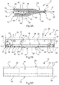
- Fig. 3A shows schematically a cross-sectional view of a caster tip arrangement 10 according to an exemplary embodiment of the invention.
- Figs. 3B and 3C each show schematically a top-view of a part of the caster tip arrangement 10 of Fig. 3A .
- Fig. 3B shows schematically a top view of a first caster plate 12 of the caster tip arrangement 10 of Fig. 3A
- Fig. 3C shows schematically a top view of a second caster plate 14 of the caster tip arrangement 10 of Fig. 3A
- Fig. 3D shows schematically a side-view of a heating device 42 of the caster tip arrangement 10 of Fig. 3A .
- the caster tip arrangement 10 of Figs. 3A to 3D comprises the same features, elements and/or characteristics as the caster tip arrangement 10 described with reference to the previous Figures 1A to 2 .
- the caster tip arrangement 10 comprises a first caster plate 12 and a second caster plate 14 arranged opposite to each other.
- the first caster plate 12 may refer to a bottom plate 12, in which the melt 101 may be held by gravitational force.
- the second caster plate 14 may refer to a top plate 14 of the caster tip arrangement 10.
- the first caster plate 12 and the second caster plate 14 are spaced apart from each other to form a guiding compartment 16, a passageway 16 and/or a passage 16 between the first caster plate 12 and the second caster plate 14 for guiding a melt 101 comprising molten metal, such as e.g. molten aluminium.
- Both the first and the second caster plates 12, 14 are manufactured from refractory material, such as e.g. refractory ceramics material.
- the first and the second caster plates 12, 14 are spaced apart from each other by a plurality of spacers 23 and/or spacing elements 23, which may be arranged e.g. on the first caster plate 12 as illustrated in Fig. 3B . However, at least a part of the spacers 23 may alternatively or additionally be arranged on the second caster plate 14.
- the spacers 23 may be arbitrarily shaped. As exemplary shown in Fig. 3B , the spacers 23 may be streamlined shaped. However, it is to be noted that the spacing elements 23 are optional only.
- the caster tip arrangement 10 further comprises an inlet 18 for receiving the melt 101, wherein the inlet 18 may e.g. be fluidly coupled and/or connected to a headbox 110 or tundish 110 (see Figs. 1B and 2 ).
- the inlet 18 comprises an inlet opening 19 formed between the first caster plate 12 and the second caster plate 14 for receiving the melt 101 and for supplying the melt 101 to the guiding compartment 16.
- the inlet 18 and/or the inlet opening 19 is arranged and/or formed on a front edge 25 of the caster tip arrangement 10.
- the caster tip arrangement 10 further comprises an outlet 20 for discharging the melt 101 in a discharging direction 22 of the caster tip arrangement 10 and/or for supplying the melt 101 e.g. to a roll arrangement 112 of a continuous caster 100, as shown in previous figures.
- the outlet 20 comprises an outlet opening 21 formed between the first caster plate 12 and the second caster plate 14.
- the outlet 20 and/or the outlet opening 21 is arranged and/or formed on a rear edge 27 of the caster tip arrangement 10, which rear edge 27 opposes and/or is arranged opposite to the front edge 25 in a transverse extension direction 24 of the caster tip arrangement 10.
- the transverse extension direction 24 may refer to a lateral extension direction 24 of the caster tip arrangement 10, and it may be parallel to the discharging direction 22 of the caster tip arrangement 10.
- a length 26 of the inlet 18 is smaller than a length 28 of the outlet 20, wherein both the length 26 of the inlet 18 and the length 28 of the outlet 20 are measured along a longitudinal extension direction 29 of the caster tip arrangement 10.
- the longitudinal extension direction 29 may be substantially parallel to the front edge 25 and/or to the rear edge 27 of the caster tip arrangement 10. Further, the longitudinal extension direction 29 is transverse and/or perpendicular to the transverse extension direction 24 and/or the discharging direction 22.
- the length 28 of the outlet 20 defines a casting width of the caster tip arrangement 10, over which casting width the melt 101 is discharged via the outlet 20.
- the divergently formed portion 30 of the guiding compartment 16 comprises two oppositely curved periphery surfaces 31 and a recess 32 arranged and/or formed on a side 33 of the first caster plate 12, which side 33 faces and/or is directed towards the second caster plate 14.
- the divergently formed portion 30 may basically have any other shape suitable for spreading the melt 101.
- the recess 32 may be a channel-like structure 32, a channel 32 and/or a notch 32 arranged on the side 33 of the first caster plate 14.
- the recess 32 extends substantially parallel to the longitudinal extension direction 29 of the caster tip arrangement 10.
- the recess 32 extends from a first lateral boundary region 34 of the caster tip arrangement 10 to a second lateral boundary region 36 of the caster tip arrangement 10, such that the melt 101 is spread via the divergently formed portion 30 and/or via the recess 32 of the divergently formed portion 30 from the inlet 18 towards the first lateral boundary region 34 and towards the second lateral boundary region 36.
- the first lateral boundary region 34 is arranged opposite to the second lateral boundary region 36 in the longitudinal extension direction 29 of the caster tip arrangement 10.
- a protrusion 39 is formed on a side 41 of the second caster plate 14, wherein the protrusion 39 at least partly engages with the recess 32.
- the protrusion 39 may be arranged parallel to the longitudinal extension direction 29 and the side 41 faces and/or opposes the first caster plate 12.
- the first lateral boundary region 34 extends from a first outer edge 35 and/or a first lateral edge 35 of the caster tip arrangement 10 in the longitudinal extension direction 29 to maximal 35% of a total length 28 of the caster tip arrangement 10.
- the first outer edge 35 may also refer to a first side panel 35 of the caster tip arrangement 10.
- the first outer edge 35 may connect the front edge 25 and the rear edge 27 of the caster tip arrangement 10.
- the total length 28 of the caster tip arrangement 10 may be substantially equal to the length 28 of the outlet 20.
- the second lateral boundary region 36 extends from a second outer edge 37 and/or a second lateral edge 37 of the caster tip arrangement 10 in the longitudinal extension direction 29 to maximal 35% of a total length 28 of the caster tip arrangement 10.
- the second outer edge 37 may also refer to a second side panel 37 of the caster tip arrangement 10.
- the second outer edge 35 may connect the front edge 25 and the rear edge 27 of the caster tip arrangement 10.
- a center region 38 of the caster tip arrangement 10 is arranged and/or located.
- the caster tip arrangement 10 further comprises a heating device 42 arranged at least partly between the first caster plate 12 and the second caster plate 14. Accordingly, the heating device 42 is at least partly arranged in the guiding compartment 16.
- the heating device 42 comprises a refractory sheet 44 manufactured from refractory material, such as e.g. refractory ceramics material and/or Silicon-Nitrite, alumina, silica, and/or other commonly used refractory materials.
- the refractory sheet 44 is at least partly arranged in the recess 32 and extends along the longitudinal extension direction 29 of the caster tip arrangement 10.
- the refractory sheet 44 may be mechanically fixed to the side 33 of the first caster plate 12.
- the heating device 42 further comprises one or more heating elements 46 arranged on and/or attached to a side 48 and/or a surface 48 of the refractory sheet 44.
- the heating elements 46 may be configured for resistively heating at least a part of the first lateral boundary region 34 and the second lateral boundary region 36.
- the heating elements 46 may alternatively be any other kind of heating element 46, such as e.g. a heating coil, an electrical heating element or the like.
- Each of the heating elements 46 may comprise at least one conductive metal strip 50 and/or at least one conductive metal element 50.
- the conductive metal strip 50 of each of the heating elements 46 may be printed on the side 48 of the refractory sheet 44.
- the heating elements 46 are arranged between the refractory sheet 44 and the side 33 of the first caster plate 12 facing the second caster plate 14.
- a mass of the heating device 42 and/or a mass of the one or more heating elements 46 may be reduced with respect to conventional heating elements and/or conventional heating devices. This in turn may allow a faster temperature change and/or a faster temperature control to be induced by the heating element with respect to conventional heating elements. Also, a precision of a temperature control by means of the printed conductive metal strip 50 may be increased with respect to conventional heating elements.
- the center region 38 of the caster tip arrangement 10 may remain unheated, and the heating device 42 may be configured to only, solely, and/or exclusively heat the first lateral boundary region 34 and/or the second lateral boundary region 36.
- the heating device 42 may be configured to heat both the first lateral boundary region 34 and the second lateral boundary region 36.
- the heating device may 42 may comprise a plurality heating elements 46 distributed substantially over the total length of the caster tip arrangement 10 along the longitudinal extension direction 29, wherein the heating device 42 may be configured to heat the heating elements 46 with variable heating intensity and/or with variable heating power.
- the heating device 42 may be configured to heat heating elements 46 arranged in the center region 38 less than heating elements 46 arranged in the first and/or second lateral boundary region 34, 36, respectively.
- the caster tip arrangement 10 optionally comprises a temperature control device 52, which comprises one or more temperature sensors 54.
- the temperature sensors 54 may be arranged on the side 48 of the refractory sheet 44 in order to determine and/or measure a temperature of the melt 101 in the first lateral boundary region 34 and/or in the second lateral boundary region 36.
- the temperature sensors 54 may be arranged near and/or adjacent to the outlet 20, such that a temperature of the melt 101 may be determined at the outlet 20. Therein, the temperature sensors 54 may be distributed over substantially the total length 28 of the outlet 20.
- the temperature control device 52 is configured to control a heating temperature of each of the heating elements 46 in response to a temperature determined by means of at least a part of the temperature sensors 54.
- each of the heating elements 46 may be associated with at least one of the temperature sensors 54, which may be arranged e.g. directly adjacent to the respective heating element 46, and the temperature control device may be configured to independently and/or individually control the heating temperature of each of the heating elements 46.
- the temperature control device 52 may be configured to control the heating temperature of all heating elements 46.
- the temperature control device 52 may be configured to control the heating temperature of all heating elements 46 arranged in the first lateral boundary region 34, to independently control the heating temperature of all heating elements 46 arranged in the second lateral boundary region 36 and/or to independently control the heating temperature of all heating elements arranged in the center region 38.
- the temperature of the melt 101 across the casting width may be controlled by supplying different heating power to different heating elements 46 of the heating device 42, wherein the heating device 42 may be configured to control the melt temperature e.g. by means of calibration values for the heating power correlating the heating power with a heating temperature of the heating elements 46.
- the melt 101 entering the inlet 18 is spread by the divergently formed portion 30 of the guiding compartment 16 and/or by the recess 32 towards the first lateral boundary region 34 and the second lateral boundary region 36, such that the melt 101 is spread over the length 28 of the outlet 20 and/or over the casting width.
- a part of the melt 101 being directed from the inlet 18 via one of the first and second lateral boundary regions 34, 36 has a longer flow path and/or residence time in the guiding compartment 16 than a part of the melt 101 travelling via the center region 38 along the discharging direction 22 from the inlet 18 to the outlet 20.
- a temperature of the melt 101 in the first and second lateral boundary regions 34, 36 may be lower than a temperature of the melt 101 in the center region 38 of the guiding compartment 16 and/or of the caster tip arrangement 10. Accordingly, a temperature gradient may exist along the length 28 of the outlet 20 and/or across the casting width. This temperature gradient and/or temperature difference may be in the range of about 1°C (about 1 Kelvin) to about 60°C (about 60 Kelvin), particularly in the range of about 5°C (about 5 Kelvin) to about 30°C (about 30 Kelvin), depending on the length 28.
- the heating device 42 is configured to minimize and/or eliminate this temperature difference and/or temperature gradient by locally heating the caster tip arrangement 10 in the first lateral boundary region 34, in the second lateral boundary region 36 and/or in the center region 38.
- the heating device 42 may be configured to heat, with the heating elements 46, at least partly the molten metal in the first lateral boundary region 34, the second lateral boundary region 36, and/or the center region 38 to a melt temperature of about 1°C (about 1 Kelvin) to about 60°C (about 60 Kelvin), particularly about 1°C (about 1 Kelvin) to about 30°C (about 30 Kelvin), and preferably about 1°C (about 1 Kelvin) to about 15°C (about 15 Kelvin), above a melting temperature and/or above a liquidus temperature of the metal contained in the melt 101 in order to minimize the temperature gradient.
- the melt 101 exiting the caster tip arrangement 10 at outlet 20 may have a homogeneous temperature. This allows to increase a productivity of a caster 100 and to reduce energy consumption because no overheating of the melt 101 may be required. Also, a quality of the casted object 103 may be improved, as explained in the summary part.
- the heating device 42 and/or the temperature control device 52 may be configured to increase the heating temperature of each of the heating elements 46 according to a distance of the respective heating element 46 from the center region 38.
- a heating element 46 arranged closer to the first outer edge 35 may be heated to a higher heating temperature than another heating element 46 arranged closer to and/or arranged in the center region 38.
- a heating element 46 arranged closer to the second outer edge 37 may be heated to a higher heating temperature than another heating element 46 arranged closer to and/or arranged in the center region 38. This way, the temperature gradient across the casting width may be further reduced.
- the caster tip arrangement 10 may comprise a plurality of heating devices 42.
- a first heating device 42 may be arranged in the first lateral boundary region 34 and a second heating device 42 may be arranged in the second lateral boundary region 36.
- a further heating device 42 may be arranged in the center region 38.
- the one or more heating devices 42 of the caster tip arrangement 10 do not necessarily have to be arranged in the recess 32, but they can rather be arranged at an arbitrary location in the first lateral boundary region 34, in the second lateral boundary region 36 and/or the center region 38.
- first caster plate 12 comprises a first curved outer region 60 and/or a first curved outer surface 60.
- the second caster plate 14 comprises a second curved outer region 62 and/or a second curved outer surface 62.
- the first and second curved outer regions 60, 62 may have equal or differing radii of curvature.
- the first and second curved regions 60, 62 may be formed to allow the caster tip arrangement 10 to be arranged as close as possible to further components of the caster 100, such as e.g. the roll arrangement 112.
- Fig. 4 shows schematically a first caster plate 12 for a caster tip arrangement 10 according to an exemplary embodiment of the invention. If not stated otherwise, the first caster plate 12 of Fig. 4 comprises the same functions, features, elements and/or characteristics as the first caster plates 12 described with reference to the previous figures.
- the divergently formed portion 30 of first caster plate 12 of Fig. 4 comprises two slanted surfaces 31 arranged transverse to the transverse extension direction 24 as well as transverse to the longitudinal extension direction 29. Accordingly, the slanted surfaces 31 may each extend diagonally from the inlet 18 to the outlet 20 such that the melt 101 is spread over the casting width.
- any other geometry of the divergently formed portion 30 is conceivable.
- first heating device 42a is arranged in the first lateral boundary region 34 and a second heating device 42 is arranged in the second lateral boundary region 36.
- first and second heating devices 42a, 42b may be operated as described above with reference to Figs. 3A to 3D .
- Fig. 5 shows a flow chart illustrating steps of a method for operating a continuous caster 100 according to an exemplary embodiment of the invention. If not stated otherwise, the continuous caster 100 comprises the same features, functions, elements, and/or characteristics as described with reference to previous figures.
- the continuous caster 100 comprises a roll arrangement 112 with at least one roll 114 for forming an object 103 from a melt 101 with molten metal and a caster tip arrangement 10, as described above with reference to previous figures.
- a first step S1 the melt 101 with molten metal is supplied to the inlet 18 of the caster tip arrangement 12.
- a second step S2 the melt 101 is guided with the guiding compartment 16 of the caster tip arrangement 12 from the inlet 18 to and/or towards the first lateral boundary region 34 and the second lateral boundary region 36 of the caster tip arrangement 10.
- a further step S3 at least a part of at least one of the first lateral boundary region 34 and the second lateral boundary region 36 of the caster tip arrangement 10 is locally heated with the heating device 42 of the caster tip arrangement 10.
- the melt 101 is supplied via the outlet 20 of the caster tip arrangement 10 to the at least one roll 114 of the roll arrangement 112.
- the object 103 is formed with the at least one roll 114 of the roll arrangement 112.
- the melt 101 may be overheated in the first lateral boundary region 34 and/or in the second lateral boundary region 36 in order to achieve a homogenous temperature of the melt 101 over the total length 28 of the outlet and in order to avoid a temperature decrease of the melt 101 at the edges of the outlet 20.
Landscapes
- Engineering & Computer Science (AREA)
- Mechanical Engineering (AREA)
- Continuous Casting (AREA)
Description
- Generally, the invention relates to casting an object from a melt comprising molten metal and/or to casting of molten metal into a solidified object, such as e.g. a sheet, a plate, a bar, an ingot, a strip or the like. Particularly, the invention relates to a caster tip arrangement for a continuous caster, a use of such caster tip arrangement in a continuous caster, a continuous caster with such caster tip arrangement, and a method for operating a continuous caster comprising such caster tip arrangement.
- For casting an object, such as e.g. a sheet, a plate, a bar, an ingot, a strip or the like, from a melt comprising molten metal, various methods and devices have been developed.
- An exemplary casting method is the so-called strip casting and/or continuous casting using a continuous caster and/or a continuous caster device, such as e.g. a block caster, a twin-roll caster and/or a twin-belt caster. Therein, a material comprising metal and/or an alloy is molten, e.g. by means of a melting furnace, and then supplied to a moving casting mold of the continuous caster, which may comprise e.g. a block chain arrangement with at least one moving block chain, a roll arrangement with at least one roll and/or a belt arrangement with at least one belt, for forming a metal strip. For the purpose of supplying the melt into a gap of the moving casting mold usually a nozzle system and/or a caster tip arrangement is used, wherein the caster tip arrangement comprises an outlet for discharging the melt and guiding the melt to the moving casting mold. The melt is then solidified and a continuous strip and/or metal band may be formed.
- Document
US 2017/0106435 A1 relates to a caster tip for a twin roll continuous strip caster for non-ferrous metals. The caster tip includes a caster tip body made primarily of ceramic material, and an electric resistance heater thermally connected to the caster tip body for pre-heating the caster tip body to a predetermined temperature before a melt is introduced into the caster tip. - Document
US 5 435 375 A relates to a titanium composite casting nozzle for a continuous caster. The casting nozzle is designed for transferring molten metal from a molten reservoir to a continuously advancing mold for casting the molten metal. The nozzle comprises a top wall, a bottom wall and two side walls forming a passage therebetween. The nozzle is fabricated from a composite material comprised of a base layer of a titanium alloy and a refractory layer bonded to the base layer. Via resistive heating, the nozzle can be pre-heated before a melt is inserted into the nozzle. - It may be an objective of the present invention to provide an improved caster tip arrangement for a continuous caster for increasing a productivity of the continuous caster and/or for improving a quality of a casted object.
- This objective is solved by the subject-matter of the independent claims, wherein further embodiments are incorporated in the dependent claims and the following description.
- A first aspect of the invention relates to a caster tip arrangement for a continuous caster for casting an object from a melt with molten metal and/or for forming an object from a melt comprising molten metal. By way of example, the object may refer to a sheet, a plate, a bar, an ingot, a strip or any other kind of object. The caster tip arrangement comprises a first caster plate, a second caster plate arranged opposite to the first caster plate, an inlet for receiving a melt with molten metal, an outlet for discharging the melt in a discharging direction of the caster tip arrangement, and at least one heating device for heating at least a part of the caster tip arrangement. The first caster plate and the second caster plate are spaced apart from each other to form a guiding compartment for guiding the melt from the inlet to the outlet. Therein, at least a portion and/or a part of the guiding compartment is divergently formed from the inlet towards the outlet, such that the guiding compartment extends from the inlet to a first lateral boundary region and a second lateral boundary region of the caster tip arrangement. The second lateral boundary region is arranged opposite to the first lateral boundary region in a longitudinal extension direction of the caster tip arrangement transverse to the discharging direction. Further, the at least one heating device is configured to locally heat the caster tip arrangement in at least one of the first lateral boundary region and the second lateral boundary region of the caster tip arrangement. In other words, the at least one heating device may be configured to heat a partial region of the caster tip arrangement, which partial region is arranged and/or located in at least one of the first lateral boundary region and the second lateral boundary region. Also, the heating device may be configured to heat the caster tip arrangement in a first heating zone arranged in the first lateral boundary region and/or in a second heating zone arranged in the second lateral boundary region. Therein, the first heating zone may refer to a partial region of the first lateral boundary region or the first heating zone may refer to the entire first lateral boundary region. Likewise, the second heating zone may refer to a partial region of the second lateral boundary region or the second heating zone may refer to the entire second lateral boundary region. Accordingly, the term first lateral boundary region may refer to the first heating zone and/or the term second lateral boundary region may refer to the second heating zone.
- Generally, the caster tip arrangement may refer to a melt distribution device, a nozzle arrangement and/or a feeding device of the continuous caster. Further, the continuous caster may refer to e.g. a strip caster for forming a strip of a material comprising metal. Particularly, the continuous caster may be configured for forming a strip, a plate, a sheet and/or a slab of material comprising e.g. aluminium, aluminium alloys, magnesium, magnesium alloys, steel, copper, lead, zinc and/or any other metal.
- The first caster plate and the second caster plate may refer to plate-like structures and/or plate-like elements. Particularly, the first caster plate and/or the second caster plate may at least partly be manufactured from refractory material, such as e.g. ceramics material. Such ceramics material may for instance comprise alumina, silica, silicon nitride, refractory ceramic fibers, earth alkaline ceramic fibres, asbestos, sodium silicate and/or any other refractory material based on oxide, nitride, carbide or carbonitride.
- The first caster plate and the second caster plate may be formed as a single part or as a plurality of parts. The first and second caster plates may be arranged substantially parallel to each other in a direction transverse to the discharging direction and/or transverse to the longitudinal extension direction, such that the guiding compartment is formed between the first and second caster plates. Optionally, the caster tip arrangement may comprise a first side panel and a second side panel. The first and second side panels may be arranged opposite to each other in the longitudinal extension direction of the caster tip arrangement. For instance, the first side panel may be arranged on a first outer edge of the caster tip arrangement and/or a first outer edge of the first and second caster plates. Likewise, the second side panel may be arranged on a second outer edge of the caster tip arrangement and/or a second outer edge of the first and second caster plates. Therein, the first and second side panels may connect the first caster plate and the second caster plate. Moreover, the first and second side panels may be configured and/or arranged to seal the guiding compartment on a first side of the caster tip arrangement and on a second side of the caster tip arrangement, respectively.
- The inlet may refer to and/or comprise an inlet opening formed between the first caster plate and the second caster plate, wherein the inlet opening may be configured to receive the melt, e.g. from a headbox and/or a tundish of the continuous caster. Particularly, the inlet may be arranged on a front edge of the caster tip arrangement.
- The outlet may refer to and/or comprise an outlet opening formed between the first caster plate and the second caster plate, wherein the outlet opening may be configured for discharging and/or supplying the melt in the discharging direction to other components of the continuous caster. Particularly, the outlet may be arranged on a rear edge of the caster tip arrangement arranged opposite to the front edge of the caster tip arrangement in the discharging direction. With respect to the inlet, the outlet may be arranged downstream of a streaming direction of the melt through the caster tip arrangement and/or through the guiding compartment, wherein the streaming direction may be substantially parallel to the discharging direction. Further, a length of the outlet may define a casting width over which the melt may be discharged. Therein, the length of the outlet and/or the casting width may be measured substantially parallel to the front edge and/or the rear edge of the caster tip arrangement. Accordingly, the length of the outlet and/or the casting width may be measured in a direction transverse and/or perpendicular to the discharging direction. Moreover, the length of the outlet may be larger than a length of the inlet measured substantially parallel to the front edge and/or the rear edge. Accordingly, also a cross-sectional area, a diameter, a perimeter and/or a circumference of the outlet may be larger than a cross-sectional area, a diameter, a perimeter and/or a circumference of the inlet.
- Generally, the discharging direction may be substantially parallel to a transverse extension direction and/or a lateral extension direction of the caster tip arrangement, which transverse extension direction may be transverse and/or perpendicular to the front edge and/or the rear edge of the caster tip arrangement. By way of example, the discharging direction may be defined by a line connecting a center point of the inlet and a center point of the outlet. Moreover, the longitudinal extension direction of the caster tip arrangement may be substantially transverse and/or perpendicular to the transverse extension direction of the caster tip arrangement.
- Further, the term "guiding compartment" may refer to a passageway and/or a passage for guiding the melt from the inlet to the outlet. The guiding compartment may be formed between the first caster plate and the second caster plate, and optionally between the first side panel and the second side panel. Therein, the guiding compartment may connect the inlet and the outlet of the caster tip arrangement. From the inlet towards the outlet, e.g. along the discharging direction and/or along the transverse extension direction of the caster tip arrangement, a diameter, a cross-sectional area and/or a circumference of the guiding compartment may increase at least in a portion of the guiding compartment, such that at least the portion of the guiding compartment is divergently formed and/or diverges in the longitudinal extension direction. In other words, at least a portion of the guiding compartment between the inlet and the outlet diverges along the longitudinal extension direction transverse to the discharging direction. By means of the at least partly divergently formed guiding compartment the melt may be spread from the inlet to the first lateral boundary region and the second lateral boundary region of the caster tip arrangement. Therein, the melt may be spread and/or distributed over and/or across at least a part of the casting width of the caster tip arrangement.
- The first lateral boundary region may refer to a first outer region of the caster tip arrangement and/or of the guiding compartment. The first lateral boundary region may extend from a first outer edge and/or a first side of the caster tip arrangement along and/or substantially parallel to the longitudinal extension direction of the caster tip arrangement. Likewise, the second lateral boundary region may refer to a second outer region of the caster tip arrangement and/or of the guiding compartment. The second lateral boundary region may extend from a second outer edge and/or a second side of the caster tip arrangement along and/or substantially parallel to the longitudinal extension direction. Therein, the first outer edge and the second outer edge may be arranged opposite to each other in the longitudinal extension direction. As described above, the caster tip arrangement may optionally comprise a first side panel arranged on the first outer edge and a second side panel arranged on the second outer edge. Accordingly, the first lateral boundary region may be arranged adjacent to the first outer edge and/or adjacent to the first side panel. Further, the second lateral boundary region may be arranged adjacent to the second outer edge and/or adjacent to the second side panel.
- Further, the term "locally heat" the caster tip arrangement may mean that the heating device is configured and/or arranged to heat a part of the caster tip arrangement in at least one of the first lateral boundary region and the second lateral boundary region. Also, the term "locally heat" may mean that the heating device is configured and/or arranged to heat the at least a part of the caster tip arrangement with locally variable heating intensity. Particularly, the heating device may be configured and/or arranged to heat only, solely and/or exclusively a partial region of the caster tip arrangement. The partial region heated by the heating device may be located in the first lateral boundary region and/or in the second lateral boundary region. By way of example, the heating device may be configured to heat a first heating zone arranged in the first lateral boundary region and/or to heat a second zone arranged in the second lateral boundary region. However, the heating device may also be configured to heat the entire first lateral boundary region and/or the entire second lateral boundary region. Preferably, the heating device may be configured and/or arranged to at least partly heat both the first lateral boundary region and the second lateral boundary region. Likewise, the heating device may be configured to heat both the first heating zone and the second heating zone. Further, the caster tip arrangement may comprise a center region arranged between the first lateral boundary region and the second lateral boundary region in the longitudinal extension direction, wherein the center region and/or melt in the center region may be heated less than the first lateral boundary region and/or less than the second lateral boundary region. However, the center region may alternatively not be heated by the heating device and/or the center region may be unheated.
- Generally, the present invention may be considered being based on the following findings and insights. In a continuous caster, such as e.g. a strip caster, a melt may be supplied from a melting furnace e.g. via a trench and/or a launder to a moving casting mold, wherein the melt should be homogeneously distributed over the casting width in terms of a volume flow and/or in terms of a temperature distribution. For this purpose, usually the caster tip arrangement is used, which may also be referred to as "caster tip" and/or as "nozzle arrangement". For minimizing heat losses in the caster tip arrangement and/or in the first and second caster plates, the first and second caster plates may be manufactured from refractory ceramic fibers formed in a vacuum forming process. Generally, the first and second caster plates may be sensitive to mechanical strain and stress, which may result in a reduced lifetime. Since the melt inserted into the inlet of the caster tip arrangement is spread by means of the guiding compartment towards the first lateral boundary region and the second lateral boundary region, a temperature gradient of the melt may be present along the longitudinal extension direction due to different flow paths, different lengths of flow paths and/or different residence times of the melt within the guiding compartment. Particularly, a temperature gradient of the melt may be present at the outlet along the length of the outlet and/or over the casting width, which may be defined by the length of the outlet. Therein, the length of the outlet and/or the casting width may be measured along and/or substantially parallel to the longitudinal extension direction of the caster tip arrangement. Specifically, a temperature of the melt may be higher in a center region of the caster tip arrangement and/or a center region of the outlet with respect to the first lateral boundary region and/or a first outer region of the outlet adjacent to the first lateral boundary region. Likewise, the temperature of the melt may be higher in the center region of the caster tip arrangement and/or a center region of the outlet with respect to the second lateral boundary region and/or a second outer region of the outlet adjacent to the second lateral boundary region. Depending on the length of the caster tip arrangement, the length of the outlet and/or the casting width, the temperature differences may be in the range of about 1°C (about 1 Kelvin) to about 60°C (about 60 Kelvin), particularly in the range of about 5°C (about 5 Kelvin) to about 30°C (about 30 Kelvin). Such inhomogeneity of the temperature may lead to varying solidification conditions of the melt, e.g. when the melt contacts a mold. In turn this may lead to quality relevant defects within the casted object, such as e.g. a casted strip. Moreover, the melt may be overheated in the center region of the caster tip arrangement and/or the center region of the outlet to ensure that the melt in the first and/or second outer regions of the outlet is not solidified before exiting the caster tip. Further, a casting velocity, which may refer to a velocity with which the melt is transferred through the caster tip arrangement, may be indirectly proportional to a maximum temperature of the melt in the caster tip arrangement. As a consequence, the casting velocity may be adapted to the maximum temperature of the melt in the caster tip arrangement. Hence, the casting velocity, a productivity and/or an efficiency of the caster may depend on the temperature gradient over the casting width.
- By heating at least a part of the first lateral boundary region and/or at least a part of the second lateral boundary region by means of the heating device, the temperature gradient over the casting width may be minimized and/or eliminated. This may result in a homogeneous temperature distribution of the melt over the entire length of the outlet and/or over the entire casting width. Accordingly, the casting velocity may be adapted to a much smaller maximum temperature, and the casting velocity may be increased due to a reduction of a heat to be dissipated. In turn, this may lead to a reduction of energy consumption, an increased efficiency and/or an increased productivity of the caster. Apart from that, defects due to varying solidification conditions may be avoided, which may lead to an increased overall quality of the casted object.
- It is to be noted that by means of the heating device also a specific temperature profile of the melt across the casting width may be adjusted and/or controlled, such that e.g. deviations in a roll cooling of a roll arrangement may be compensated by the temperature profile. This may further improve a quality of the casted object.
- Apart from the above-mentioned advantages, actively controlling the temperature of the caster tip arrangement and/or of the melt in the guiding compartment, particularly controlling the temperature of melt near the first and/or second lateral boundary regions, may allow to use stable and/or less sensitive ceramics materials for the first and/or second caster plate, e.g. because the higher heat losses due to enhanced thermal conductivity of more stable and more dense materials might be compensated by the heating device and/or because strain and stress in the first and second caster plates may be reduced. In turn, this may increase overall equipment efficiency and/or reduce downtime and maintenance time for the caster. Also, a contamination of the casted object with material of the caster tip arrangement may be reduced and/or avoided, e.g. since spacers normally used to ensure separation of the first caster plate and the second caster plate may be avoided.
- According to an embodiment, the first lateral boundary region extends from a first outer edge of the caster tip arrangement to maximal 35% of a total length of the caster tip arrangement in the longitudinal extension direction of the caster tip arrangement. Alternatively or additionally the second lateral boundary region extends from a second outer edge of the caster tip arrangement to maximal 35% of a total length of the caster tip arrangement in the longitudinal extension direction. Accordingly, each of the first lateral boundary region and the second lateral boundary region may comprise an area of maximal 35% of a total area of the caster tip arrangement. Also, each of the first lateral boundary region and the second lateral boundary region may comprise a volume of maximal 35% of a total volume of the caster tip arrangement and/or of a total volume of the guiding compartment. By actively heating only a part of or the entire first and/or second lateral boundary region, it may be ensured that the temperature gradient over the length of the outlet and/or over the casting width is minimized.
- According to an embodiment, the heating device is configured to heat the melt in at least a part of at least one of the first lateral boundary region and the second lateral boundary region to a melt temperature of about 1°C (about 1 Kelvin) to about 60°C (about 60 Kelvin) above a melting temperature of the molten metal comprised in the melt, particularly a melt temperature of 1°C (about 1 Kelvin) to about 30°C (about 30 Kelvin) above the melting temperature, and preferably a melt temperature of about 1°C(about 1 Kelvin) to about 15°C (about 15 Kelvin) above the melting temperature. This may allow to minimize and/or eliminate the temperature gradient and/or temperature differences of the melt across the casting width. Alternatively or additionally the at least one heating device is configured to heat the melt in at least a part of at least one of the first lateral boundary region and the second lateral boundary region to a temperature of about 1°C (about 1 Kelvin) to about 60°C (about 60 Kelvin), particularly about 1°C (about 1 Kelvin) to about 30°C (about 30 Kelvin), and preferably about 1°C (about 1 Kelvin) to about 15°C (about 15 Kelvin), above a liquidus temperature of the melt, of the molten metal and/or of a molten alloy. By way of example, the melt may comprise aluminium, which may have a liquidus temperature of about 660°C (about 933.15 Kelvin). By heating at least a part of the first lateral boundary region and the second lateral boundary region as well as the melt crossing the first and/or second lateral boundary region, the melt may have a homogeneous temperature of about 661°C (about 934.15 Kelvin) to about 690°C (about 963.15 Kelvin), preferably about 670°C (about 943.15 Kelvin), at the outlet over the entire casting width. Accordingly, the heating device may be configured to heat the molten metal in at least a part of at least one of the first lateral boundary region and the second lateral boundary region to a melt temperature of about 661°C (about 934.15 Kelvin) to about 720 °C (about 993.15 Kelvin).
- In accordance with the above-mentioned temperatures and/or temperature differences over the casting width, the heating device may be configured to provide an appropriate heating power. This heating power may depend on a strip speed v of the formed strip, a strip thickness d of the formed strip, and a temperature difference ΔT between a center and lateral edges of the strip. The heating device may be configured to compensate the temperature difference ΔT over a width W of the heating device by providing a heating power P. The heating power P normalized to the width W P/W is given as the product of the strip speed v, the strip thickness d, the temperature difference ΔT, a thermal capacity, and a density of the molten metal. Assuming typical values for these parameters, particularly a temperature difference of about 15°C, a strip speed of about 0.05 m/s, a strip thickness of about 0.005 m, a thermal capacity of about 1000 J/K/kg for aluminium, and a density of about 2700 kg/m3 for aluminium, the heating device may be configured to provide a normalized heating power P/W of about 10125 Watt/meter. Accordingly, the heating device may be configured to provide about 10 kW heating power per meter width of the heating device.
- According to an embodiment, the heating device comprises at least one heating element arranged between the first caster plate and the second caster plate. The heating device may also comprise a plurality of heating elements arranged between the first caster plate and the second caster plate. Particularly, at least one heating element may be arranged in the guiding compartment and/or may be in direct contact with the guiding compartment. This may allow to directly heat the melt within the guiding compartment and/or to increase a heat input into the melt. Also, a temperature of the melt may be controlled more precisely and/or energy may be saved. However, it should be noted that the at least one heating element may also be arranged on an outer surface of at least one of the first caster plate and the second caster plate. Generally, the heating element may be configured to actively heat at least a part of at least one of the first lateral boundary region and the second lateral boundary region. The at least one heating element may be e.g. an electrical heating element, a resistive heating element and/or any other kind of heating element.
- According to an embodiment, the heating device comprises at least one heating element for resistively heating at least a part of at least one of the first lateral boundary region and the second lateral boundary region of the caster tip arrangement. Resistive heating may be advantageous in terms of an achievable maximum heating temperature and/or in terms of energy consumption.
- According to an embodiment, the heating device comprises a refractory sheet and/or a ceramics sheet and at least one heating element arranged on a surface and/or a side of the refractory sheet. The refractory sheet may refer to a sheet, a plate, a bar and/or a slab of refractory material, such as e.g. refractory ceramics material. The refractory sheet may comprise the same material as the first and/or the second caster plates. The refractory sheet and the heating element may be at least partly arranged in the guiding compartment, in direct contact with the guiding compartment and/or between the first caster plate and the second caster plate. This may allow to directly contact the refractory sheet with the melt, which may further increase a heat input and/or a heat flow into the melt. By way of example the refractory sheet with the at least one heating element may refer to an insert part of the heating device, which may be at least partly inserted into the guiding compartment to locally and/or actively heat a part and/or a partial region of the caster tip arrangement.
- According to an embodiment, the heating device comprises a refractory sheet comprising at least one of Silicon-Nitrite material, alumina material, silica material, and/or any other commonly used refractory materials. By way of example, Silicon-Nitrite may be particularly advantageous in terms of its refractory properties, thermal conductivity and wettability with aluminum melt for processing of molten aluminium or aluminium alloys.
- According to an embodiment, the at least one heating element is arranged between the refractory sheet and one of the first caster plate and the second caster plate. Accordingly, the at least one heating element may be in direct contact with a side of one of the first caster plate and the second caster plate, which side faces the other one of the first and the second caster plate,
According to an embodiment, the at least one heating element comprises at least one conductive metal strip and/or at least one conductive metal element arranged on the surface and/or the side of the refractory sheet for resistively heating at least a part of at least one of the first lateral boundary region and the second lateral boundary region of the caster tip arrangement. The conductive metal element may e.g. be printed on the surface of the refractory sheet. The conductive metal element may be arranged and/or printed in an arbitrary pattern on the surface of the refractory sheet, such as e.g. a coil-like pattern. By printing the conductive metal element of the at least one heating device on the surface and/or the side of the refractory sheet, a mass of the heating device and/or a mass of the heating element may be reduced with respect to conventional heating elements and/or conventional heating devices. This in turn may allow a faster temperature change and/or a faster temperature control to be induced by the heating element with respect to conventional heating elements. Also, a precision of a temperature control by means of the printed conductive metal strip may be increased with respect to conventional heating elements. - According to an embodiment, the caster tip arrangement comprises a center region arranged between the first lateral boundary region and the second lateral boundary region in the longitudinal extension direction, wherein the at least one heating device is configured to heat the center region of the caster tip arrangement less than the first lateral boundary region and/or less than the second lateral boundary region of the caster tip arrangement. Accordingly, the at least one heating device may be configured to independently and/or separately control the temperature of the melt in the first lateral boundary region, the second lateral boundary region and/or the center region of the caster tip arrangement, such that temperature differences of the melt across the casting width at the outlet may be minimized and/or eliminated.
- Generally, the heating device may be configured to heat a part of the melt having a longer residence time in the guiding compartment more than another part of the melt flowing directly from the inlet to the outlet, i.e. flowing along the shortest way through the guiding compartment. Therein, the residence time may refer to time the melt spends within the guiding compartment while flowing from the inlet to the outlet. By way of example, the heating device may comprise a plurality of independently controllable heating elements, wherein at least one heating element may be arranged in the first lateral boundary region, at least one heating element may be arranged in the second lateral boundary region and at least one heating element may be arranged in the center region between the first and second lateral boundary regions. The heating device may, thus, be configured to heat a part of the melt crossing the center region less than further parts of the melt crossing the first and/or second lateral boundary region.
- According to an embodiment, the first caster plate comprises a recess and/or a notch on a side and/or on a surface of the first caster plate facing the second caster plate, wherein the recess extends from the first lateral boundary region to the second lateral boundary region along the longitudinal extension direction of the caster tip arrangement, such that the melt is spread by the recess from the inlet to the first lateral boundary region and the second lateral boundary region of the caster tip arrangement. The recess may e.g. be a notch, a channel-like structure and/or a channel formed on the side of the first caster plate. The melt and/or molten material entering the inlet may be guided by the guiding compartment to the recess, in which the melt may be directed and/or spread towards the first and second lateral boundary regions. Accordingly, the melt may be distributed via the recess over at least a part of the length of the caster tip arrangement and/or over at least a part of the casting width.
- According to an embodiment, at least a part of the heating device is arranged in the recess. Particularly, at least one heating element of the heating device may be arranged in the recess in the first lateral boundary region of the caster tip arrangement. Alternatively or additionally, at least one heating clement of the heating device may be arranged in the recess in the second lateral boundary region. Also, a refractory sheet of the heating device may at least partly be arranged in the recess. Particularly, the heating device may comprise a first heating element and a second heating element both arranged on a side of the refractory sheet. Therein, the refractory sheet may be arranged in the recess such that the first heating element may be arranged and/or located in the first lateral boundary region and such that the second heating element may be arranged and/or located in the second lateral boundary region. By arranging at least a part of the heating device in the recess, the melt exiting the recess may have a homogenous temperature distribution along the longitudinal extension direction of the caster tip arrangement.
- According to an embodiment, the caster tip arrangement further comprises a temperature control device coupled to the heating device, wherein the temperature control device comprises at least one temperature sensor for determining a temperature of the melt in at least a part of the caster tip arrangement and/or in at least a part of the guiding compartment. By means of the temperature control device a heating temperature of the heating device and/or of the at least one heating element of the heating device may be actively controlled in response to a measured temperature. This may allow to further reduce and/or minimize a temperature gradient of the melt along the longitudinal extension direction of the caster tip arrangement. The heating device may comprise a plurality of heating elements and the temperature control device may comprise a plurality of temperature sensors, wherein each temperature sensor may be associated with at least one of the heating elements. Also, pairs of a heating element and a temperature sensor may be distributed and/or arranged in the first lateral boundary region, the second lateral boundary region and/or the center region. Therein, each of the heating elements may be independently controlled by the temperature control device in accordance with a temperature determined by the temperature sensor associated with the respective heating element. By way of example, the temperature control device may comprise at least one first temperature sensor arranged in the first lateral boundary region for determining the melt temperature in the first lateral boundary region. Further, the temperature control device may comprise at least one second temperature sensor arranged in the second lateral boundary region for determining the melt temperature in the second lateral boundary region. The temperature control device may also comprise at least one further temperature sensor arranged in the center region of the caster tip arrangement for determining the melt temperature in the center region of the caster tip arrangement.
- Alternatively or additionally the temperature control device may comprise a plurality of temperature sensors arranged near and/or adjacent to the outlet. The temperature sensors may be distributed over the total length of the caster tip and/or over the casting width, such that the temperature may be determined by means of the temperature sensors across substantially the entire casting width.
- It is to be noted, however, that the temperature sensors are optional only. The temperature of the melt across the casting width may be controlled by supplying different heating power to different heating elements of the heating device, wherein the heating device may be configured to control the melt temperature e.g. by means of calibration values for the heating power correlating the heating power with a heating temperature of a heating element.
- A second aspect of the invention relates to a use of a caster tip arrangement, as described above and in the following, in a continuous caster for casting an object from a melt comprising molten metal, such as e.g. aluminium.
- A third aspect of the invention relates to a continuous caster and/or a casting device, such as e.g. a strip-caster. The continuous caster comprises a roll arrangement with at least one roll for forming an object from a melt with molten metal, and a caster tip arrangement, as described above and in the following. Therein, the caster tip arrangement is configured to supply the melt via the outlet of the caster tip arrangement to the at least one roll of the roll arrangement, such that the object may be formed. Generally, the continuous caster may be a roll caster, a belt caster and/or a block caster, wherein in the two latter cases the at least one roll may be configured for driving a belt of the roll arrangement to form the object.
- It should be noted that features, elements, functions and/or characteristics of the caster tip arrangement, as described above and in the following, may be features, elements, functions and/or characteristics of the continuous caster, as described above and in the following. Vice versa, features, elements, functions and/or characteristics of the continuous caster, as described above and in the following, may be features, elements, functions and/or characteristics of the caster tip arrangement, as described above and in the following.
- According to an embodiment, the roll arrangement comprises at least two counter-rotating rolls, wherein the at least two counter-rotating rolls are spaced apart from each other by a gap. Therein, the caster tip arrangement is configured to supply the melt via the outlet of the caster tip arrangement to the gap between the at least two counter-rotating rolls. By way of example, the continuous caster may be a so-called twin roll caster, by means of which a strip of metal, e.g. an aluminium strip, may be produced directly from the melt in one process step that can combine casting and rolling between the two counter rotating rolls. The melt may be guided horizontally through the caster tip arrangement into the gap between the counter rotating rolls, which may e.g. be internally water-cooled to dissipate heat. Each of the rolls may consist of a core and a shrink fitted shell, which provides a moving mold surface to the melt. The rolls may e.g. be made from steel and/or copper and/or alloys and combinations thereof. The melt may be discharged at the outlet of the caster tip arrangement in a certain distance to a center line between center points of the rolls. This distance is commonly referred to as set-back. Solidification of the melt may start at the contact points between the melt and the two rolls. Through ongoing solidification strip shells on both roll surfaces may be formed, which meet at the so-called kissing point and unify under the roll pressure to one strip. At this point, solidification may be finalized and rolling deformation may take place uniformly within the roll gap.
- A fourth aspect of the invention relates to a method for operating a continuous caster. The continuous caster comprises a roll arrangement with at least one roll for forming an object from a melt with molten metal and a caster tip arrangement, as described above and in the following. The method comprises the steps of:
- supplying a melt with molten metal to the inlet of the caster tip arrangement;
- guiding, with the guiding compartment of the caster tip arrangement, the melt from the inlet to and/or towards the first lateral boundary region and the second lateral boundary region of the caster tip arrangement;
- heating, with the heating device of the caster tip arrangement, at least a part of at least one of the first lateral boundary region and the second lateral boundary region of the caster tip arrangement;
- supplying the melt via the outlet of the caster tip arrangement to the at least one roll of the roll arrangement; and
- forming, with the at least one roll of the roll arrangement, an object from the melt.
- It should be noted that features, elements, functions and/or characteristics of the caster tip arrangement and/or the continuous caster, as described above and in the following, may be features, elements, functions, characteristics and/or steps of the method, as described above and in the following. Vice versa, features, elements, functions, characteristics and/or steps of the method, as described above and in the following, may be features, elements, functions and/or characteristics of the caster tip arrangement and/or the continuous caster, as described above and in the following.
- These and other aspects of the invention will be apparent from and elucidated with reference to the embodiments described hereinafter.
- The subject-matter of the invention will be explained in more detail in the following with reference to exemplary embodiments which are illustrated in the attached figures.
-
Fig. 1A shows schematically a continuous casting line according to an exemplary embodiment of the invention. -
Fig. 1B shows schematically a cross-sectional view of a part of the continuous caster ofFig. 1A . -
Fig. 2 shows schematically a cross-sectional view of a part of a continuous caster according to an exemplary embodiment of the invention. -
Fig. 3A shows schematically a cross-sectional view of a caster tip arrangement according to an exemplary embodiment of the invention. -
Figs. 3B and 3C each show schematically a top-view of a part of the caster tip arrangement ofFig. 3A . -
Fig. 3D shows schematically a side view of a heating device of the caster tip arrangement ofFig. 3A . -
Fig. 4 shows schematically a first caster plate for a caster tip arrangement according to an exemplary embodiment of the invention. -
Fig. 5 shows a flow chart illustrating steps of a method for operating a continuous caster according to an exemplary embodiment of the invention. - In principle, identical or similar parts are provided with the same reference symbols in the figures. The figures are not to scale.
-
Fig. 1A shows schematically acontinuous casting line 100, acontinuous caster arrangement 100 and/or acontinuous caster 100 according to an exemplary embodiment of the invention.Fig. 1B shows schematically a cross-sectional view of a part of thecontinuous casting line 100 ofFig. 1A . Thecontinuous casting line 100 may be a so-calledstrip caster 100 for casting and/or forming a strip comprising metal, particularly a strip comprising aluminium. - The
continuous casting line 100 and/or thecontinuous caster 100 comprises afurnace 102 for melting material comprising metal, particularly comprising aluminium. By means of thefurnace 102 the material is heated above a melting temperature of the metal to generate amelt 101 comprising molten metal. - The
continuous casting line 100 and/or thecontinuous caster 100 further comprises a holdingfurnace 104 for further heating themelt 101 and/or for keeping themelt 101 at a certain temperature above the melting temperature. Thecontinuous caster 100 further comprises amelt treatment arrangement 106 for filtering and/or degassing and/or improving the quality of themelt 101. - The
continuous casting line 100 and/or thecontinuous caster 100 further comprises amelt distribution device 108 with atundish 110 and/or aheadbox 110. Themelt distribution device 108 further comprises acaster tip arrangement 10 fluidly coupled and/or connected to thetundish 110 orheadbox 110. As will be described in more detail with reference toFigs. 4A to 4 , thecaster tip arrangement 10 comprises afirst caster plate 12 and asecond caster plate 14 arranged opposite to each other to form aguiding compartment 16 between thefirst caster plate 12 and thesecond caster plate 14. By means of the guidingcompartment 16, themelt 101 is guided from aninlet 18 of thecaster tip arrangement 10 to anoutlet 20 of thecaster tip arrangement 10. Therein, theinlet 18 may be fluidly coupled to an outlet of thetundish 110. - The
continuous casting line 100 and/or thecontinuous caster 100 further comprises aroll arrangement 112 for forming anobject 103 from the melt. Theobject 103 in the exemplary embodiment illustrated inFigs. 1A and 1B is astrip 103 comprising metal, particularly astrip 103 comprising aluminium. Theroll arrangement 112 comprises twocounter-rotating rolls gap 116. Therein, thecaster tip arrangement 10 is configured to supply themelt 101 via theoutlet 20 of thecaster tip arrangement 10 to thegap 116 between the twocounter-rotating rolls roll arrangement 112. - By means of the
continuous casting line 100 and/or thecontinuous caster 100 thestrip 103 comprising metal may be produced directly from themelt 101 in one process step that combines casting and rolling between the twocounter rotating rolls melt 101 may be guided horizontally through thecaster tip arrangement 10 into thegap 116 between thecounter rotating rolls rolls core shell melt 101. Therolls melt 101 may be discharged at theoutlet 20 of thecaster tip arrangement 10 in a certain distance to acenter line 121 between center points of therolls melt 101 may start at the contact points between themelt 101 and the tworolls strip 103, wherein the roll pressure is illustrated inFig. 1B by the two antiparallel arrows. At this point, solidification may be finalized and rolling deformation may take place uniformly down to thecenter line 121. On the solid side of thecasting line 100 and/or theroll arrangement 112, a release agent, e.g. an aqueous graphite suspension, may be applied by at least onespraying device 122 of thecontinuous caster 100. Such spraying process may provide a thermal barrier for heat flow between solidifying metal and the roll surface as well as it may avoid sticking of thestrip 103 on therolls center line 121. - The
continuous caster 100 further comprises acoiler 124 for coiling thestrip 103. -
Fig. 2 shows schematically a cross-sectional view of a part of acontinuous caster 100 according to an exemplary embodiment of the invention. Particularly,Fig. 2 shows a cross-sectional view of amelt distribution device 108 and aroll arrangement 112. If not stated otherwise, themelt distribution device 108 and theroll arrangement 112 ofFig. 2 comprise the same features, elements and/or characteristics as themelt distribution device 108 and theroll arrangement 112 shown inFigs. 1A and 1B . - In contrast to the
roll arrangement 112 shown inFigs. 1A and 1B , theroll arrangement 112 shown inFig. 2 comprises in total four rolls 114. More specifically, theroll arrangement 112 comprises twopairs - The
roll arrangement 112 further comprises twocounter-rotating belts pairs co-rotating rolls 114 drives one of thebelts object 103. Theobject 103 may for instance be astrip 103 and/or aslab 103 comprising metal, e.g. aluminium. - Similarly, to the
continuous caster 100 described with reference toFigs. 1A and 1B , themelt 101 may be provided via thetundish 110 to theinlet 18 of thecaster tip arrangement 10 and guided by the guidingcompartment 16 of thecaster tip arrangement 10 to theoutlet 20 of thecaster tip arrangement 10. Via theoutlet 20 of thecaster tip arrangement 10, themelt 101 is supplied to agap 116 formed between the twocounter-rotating belts gap 116 themelt 101 may be solidified and theobject 103 may be formed by rolling deformation, e.g. in a roller mill. - The
roll arrangement 112 further comprises two belt quenchdevices devices belts -
Fig. 3A shows schematically a cross-sectional view of acaster tip arrangement 10 according to an exemplary embodiment of the invention.Figs. 3B and 3C each show schematically a top-view of a part of thecaster tip arrangement 10 ofFig. 3A . Inter alia,Fig. 3B shows schematically a top view of afirst caster plate 12 of thecaster tip arrangement 10 ofFig. 3A, and Fig. 3C shows schematically a top view of asecond caster plate 14 of thecaster tip arrangement 10 ofFig. 3A . Further,Fig. 3D shows schematically a side-view of aheating device 42 of thecaster tip arrangement 10 ofFig. 3A . If not stated otherwise, thecaster tip arrangement 10 ofFigs. 3A to 3D comprises the same features, elements and/or characteristics as thecaster tip arrangement 10 described with reference to the previousFigures 1A to 2 . - The
caster tip arrangement 10 comprises afirst caster plate 12 and asecond caster plate 14 arranged opposite to each other. Therein, thefirst caster plate 12 may refer to abottom plate 12, in which themelt 101 may be held by gravitational force. In contrast, thesecond caster plate 14 may refer to atop plate 14 of thecaster tip arrangement 10. Thefirst caster plate 12 and thesecond caster plate 14 are spaced apart from each other to form aguiding compartment 16, apassageway 16 and/or apassage 16 between thefirst caster plate 12 and thesecond caster plate 14 for guiding amelt 101 comprising molten metal, such as e.g. molten aluminium. Both the first and thesecond caster plates - The first and the
second caster plates spacers 23 and/orspacing elements 23, which may be arranged e.g. on thefirst caster plate 12 as illustrated inFig. 3B . However, at least a part of thespacers 23 may alternatively or additionally be arranged on thesecond caster plate 14. Thespacers 23 may be arbitrarily shaped. As exemplary shown inFig. 3B , thespacers 23 may be streamlined shaped. However, it is to be noted that thespacing elements 23 are optional only. - The
caster tip arrangement 10 further comprises aninlet 18 for receiving themelt 101, wherein theinlet 18 may e.g. be fluidly coupled and/or connected to aheadbox 110 or tundish 110 (seeFigs. 1B and 2 ). Theinlet 18 comprises aninlet opening 19 formed between thefirst caster plate 12 and thesecond caster plate 14 for receiving themelt 101 and for supplying themelt 101 to theguiding compartment 16. Theinlet 18 and/or theinlet opening 19 is arranged and/or formed on afront edge 25 of thecaster tip arrangement 10. - The
caster tip arrangement 10 further comprises anoutlet 20 for discharging themelt 101 in a dischargingdirection 22 of thecaster tip arrangement 10 and/or for supplying themelt 101 e.g. to aroll arrangement 112 of acontinuous caster 100, as shown in previous figures. Theoutlet 20 comprises anoutlet opening 21 formed between thefirst caster plate 12 and thesecond caster plate 14. Theoutlet 20 and/or theoutlet opening 21 is arranged and/or formed on arear edge 27 of thecaster tip arrangement 10, whichrear edge 27 opposes and/or is arranged opposite to thefront edge 25 in atransverse extension direction 24 of thecaster tip arrangement 10. Thetransverse extension direction 24 may refer to alateral extension direction 24 of thecaster tip arrangement 10, and it may be parallel to the dischargingdirection 22 of thecaster tip arrangement 10. - A
length 26 of theinlet 18 is smaller than alength 28 of theoutlet 20, wherein both thelength 26 of theinlet 18 and thelength 28 of theoutlet 20 are measured along alongitudinal extension direction 29 of thecaster tip arrangement 10. Thelongitudinal extension direction 29 may be substantially parallel to thefront edge 25 and/or to therear edge 27 of thecaster tip arrangement 10. Further, thelongitudinal extension direction 29 is transverse and/or perpendicular to thetransverse extension direction 24 and/or the dischargingdirection 22. Therein, thelength 28 of theoutlet 20 defines a casting width of thecaster tip arrangement 10, over which casting width themelt 101 is discharged via theoutlet 20. - As the
length 28 of theoutlet 20 is larger than thelength 26 of theinlet 18, at least aportion 30 of the guidingcompartment 16 is divergently formed from theinlet 18 towards theoutlet 20, such that themelt 101 is spread over at least a part of thelength 28 of theoutlet 18 and/or the casting width. To spread themelt 101, the divergently formedportion 30 of the guidingcompartment 16 comprises two oppositely curved periphery surfaces 31 and arecess 32 arranged and/or formed on aside 33 of thefirst caster plate 12, whichside 33 faces and/or is directed towards thesecond caster plate 14. However, it is to be noted that the divergently formedportion 30 may basically have any other shape suitable for spreading themelt 101. - The
recess 32 may be a channel-like structure 32, achannel 32 and/or anotch 32 arranged on theside 33 of thefirst caster plate 14. Therecess 32 extends substantially parallel to thelongitudinal extension direction 29 of thecaster tip arrangement 10. Moreover, therecess 32 extends from a firstlateral boundary region 34 of thecaster tip arrangement 10 to a secondlateral boundary region 36 of thecaster tip arrangement 10, such that themelt 101 is spread via the divergently formedportion 30 and/or via therecess 32 of the divergently formedportion 30 from theinlet 18 towards the firstlateral boundary region 34 and towards the secondlateral boundary region 36. Therein, the firstlateral boundary region 34 is arranged opposite to the secondlateral boundary region 36 in thelongitudinal extension direction 29 of thecaster tip arrangement 10. To efficiently spread themelt 101 in theguiding compartment 16, aprotrusion 39 is formed on aside 41 of thesecond caster plate 14, wherein theprotrusion 39 at least partly engages with therecess 32. Theprotrusion 39 may be arranged parallel to thelongitudinal extension direction 29 and theside 41 faces and/or opposes thefirst caster plate 12. - The first
lateral boundary region 34 extends from a firstouter edge 35 and/or a firstlateral edge 35 of thecaster tip arrangement 10 in thelongitudinal extension direction 29 to maximal 35% of atotal length 28 of thecaster tip arrangement 10. The firstouter edge 35 may also refer to afirst side panel 35 of thecaster tip arrangement 10. The firstouter edge 35 may connect thefront edge 25 and therear edge 27 of thecaster tip arrangement 10. Thetotal length 28 of thecaster tip arrangement 10 may be substantially equal to thelength 28 of theoutlet 20. Similarly, the secondlateral boundary region 36 extends from a secondouter edge 37 and/or a secondlateral edge 37 of thecaster tip arrangement 10 in thelongitudinal extension direction 29 to maximal 35% of atotal length 28 of thecaster tip arrangement 10. The secondouter edge 37 may also refer to asecond side panel 37 of thecaster tip arrangement 10. The secondouter edge 35 may connect thefront edge 25 and therear edge 27 of thecaster tip arrangement 10. Between the firstlateral boundary region 34 and the secondlateral boundary region 36, acenter region 38 of thecaster tip arrangement 10 is arranged and/or located. - The
caster tip arrangement 10 further comprises aheating device 42 arranged at least partly between thefirst caster plate 12 and thesecond caster plate 14. Accordingly, theheating device 42 is at least partly arranged in theguiding compartment 16. Theheating device 42 comprises arefractory sheet 44 manufactured from refractory material, such as e.g. refractory ceramics material and/or Silicon-Nitrite, alumina, silica, and/or other commonly used refractory materials. Therefractory sheet 44 is at least partly arranged in therecess 32 and extends along thelongitudinal extension direction 29 of thecaster tip arrangement 10. Therefractory sheet 44 may be mechanically fixed to theside 33 of thefirst caster plate 12. - The
heating device 42 further comprises one ormore heating elements 46 arranged on and/or attached to aside 48 and/or asurface 48 of therefractory sheet 44. By way of example, theheating elements 46 may be configured for resistively heating at least a part of the firstlateral boundary region 34 and the secondlateral boundary region 36. However, theheating elements 46 may alternatively be any other kind ofheating element 46, such as e.g. a heating coil, an electrical heating element or the like. Each of theheating elements 46 may comprise at least oneconductive metal strip 50 and/or at least oneconductive metal element 50. By way of example, theconductive metal strip 50 of each of theheating elements 46 may be printed on theside 48 of therefractory sheet 44. Further, theheating elements 46 are arranged between therefractory sheet 44 and theside 33 of thefirst caster plate 12 facing thesecond caster plate 14. By printing theconductive metal element 50 of the at least oneheating device 42 on thesurface 48 and/or theside 48 of therefractory sheet 44, a mass of theheating device 42 and/or a mass of the one ormore heating elements 46 may be reduced with respect to conventional heating elements and/or conventional heating devices. This in turn may allow a faster temperature change and/or a faster temperature control to be induced by the heating element with respect to conventional heating elements. Also, a precision of a temperature control by means of the printedconductive metal strip 50 may be increased with respect to conventional heating elements. - It is to be noted that in the
center region 38 noheating element 46 may be present and/or arranged. Accordingly, thecenter region 38 of thecaster tip arrangement 10 may remain unheated, and theheating device 42 may be configured to only, solely, and/or exclusively heat the firstlateral boundary region 34 and/or the secondlateral boundary region 36. Particularly, theheating device 42 may be configured to heat both the firstlateral boundary region 34 and the secondlateral boundary region 36. Alternatively or additionally, the heating device may 42 may comprise aplurality heating elements 46 distributed substantially over the total length of thecaster tip arrangement 10 along thelongitudinal extension direction 29, wherein theheating device 42 may be configured to heat theheating elements 46 with variable heating intensity and/or with variable heating power. Particularly, theheating device 42 may be configured to heatheating elements 46 arranged in thecenter region 38 less thanheating elements 46 arranged in the first and/or secondlateral boundary region - Further, the
caster tip arrangement 10 optionally comprises atemperature control device 52, which comprises one ormore temperature sensors 54. Similarly to theheating elements 46, thetemperature sensors 54 may be arranged on theside 48 of therefractory sheet 44 in order to determine and/or measure a temperature of themelt 101 in the firstlateral boundary region 34 and/or in the secondlateral boundary region 36. Alternatively or additionally, thetemperature sensors 54 may be arranged near and/or adjacent to theoutlet 20, such that a temperature of themelt 101 may be determined at theoutlet 20. Therein, thetemperature sensors 54 may be distributed over substantially thetotal length 28 of theoutlet 20. - The
temperature control device 52 is configured to control a heating temperature of each of theheating elements 46 in response to a temperature determined by means of at least a part of thetemperature sensors 54. Therein, each of theheating elements 46 may be associated with at least one of thetemperature sensors 54, which may be arranged e.g. directly adjacent to therespective heating element 46, and the temperature control device may be configured to independently and/or individually control the heating temperature of each of theheating elements 46. Alternatively, thetemperature control device 52 may be configured to control the heating temperature of allheating elements 46. Alternatively, thetemperature control device 52 may be configured to control the heating temperature of allheating elements 46 arranged in the firstlateral boundary region 34, to independently control the heating temperature of allheating elements 46 arranged in the secondlateral boundary region 36 and/or to independently control the heating temperature of all heating elements arranged in thecenter region 38. - It is to be noted, however, that the
temperature sensors 54 are optional only. The temperature of themelt 101 across the casting width may be controlled by supplying different heating power todifferent heating elements 46 of theheating device 42, wherein theheating device 42 may be configured to control the melt temperature e.g. by means of calibration values for the heating power correlating the heating power with a heating temperature of theheating elements 46. - As explained in detail in the summary part, the
melt 101 entering theinlet 18 is spread by the divergently formedportion 30 of the guidingcompartment 16 and/or by therecess 32 towards the firstlateral boundary region 34 and the secondlateral boundary region 36, such that themelt 101 is spread over thelength 28 of theoutlet 20 and/or over the casting width. As a consequence, a part of themelt 101 being directed from theinlet 18 via one of the first and secondlateral boundary regions guiding compartment 16 than a part of themelt 101 travelling via thecenter region 38 along the dischargingdirection 22 from theinlet 18 to theoutlet 20. Due to the differing flow paths and/or residence times, a temperature of themelt 101 in the first and secondlateral boundary regions melt 101 in thecenter region 38 of the guidingcompartment 16 and/or of thecaster tip arrangement 10. Accordingly, a temperature gradient may exist along thelength 28 of theoutlet 20 and/or across the casting width. This temperature gradient and/or temperature difference may be in the range of about 1°C (about 1 Kelvin) to about 60°C (about 60 Kelvin), particularly in the range of about 5°C (about 5 Kelvin) to about 30°C (about 30 Kelvin), depending on thelength 28. - The
heating device 42 is configured to minimize and/or eliminate this temperature difference and/or temperature gradient by locally heating thecaster tip arrangement 10 in the firstlateral boundary region 34, in the secondlateral boundary region 36 and/or in thecenter region 38. By way of example, theheating device 42 may be configured to heat, with theheating elements 46, at least partly the molten metal in the firstlateral boundary region 34, the secondlateral boundary region 36, and/or thecenter region 38 to a melt temperature of about 1°C (about 1 Kelvin) to about 60°C (about 60 Kelvin), particularly about 1°C (about 1 Kelvin) to about 30°C (about 30 Kelvin), and preferably about 1°C (about 1 Kelvin) to about 15°C (about 15 Kelvin), above a melting temperature and/or above a liquidus temperature of the metal contained in themelt 101 in order to minimize the temperature gradient. This way, themelt 101 exiting thecaster tip arrangement 10 atoutlet 20 may have a homogeneous temperature. This allows to increase a productivity of acaster 100 and to reduce energy consumption because no overheating of themelt 101 may be required. Also, a quality of thecasted object 103 may be improved, as explained in the summary part. - It is to be noted, that the
heating device 42 and/or thetemperature control device 52 may be configured to increase the heating temperature of each of theheating elements 46 according to a distance of therespective heating element 46 from thecenter region 38. In other words, aheating element 46 arranged closer to the firstouter edge 35 may be heated to a higher heating temperature than anotherheating element 46 arranged closer to and/or arranged in thecenter region 38. Similarly, aheating element 46 arranged closer to the secondouter edge 37 may be heated to a higher heating temperature than anotherheating element 46 arranged closer to and/or arranged in thecenter region 38. This way, the temperature gradient across the casting width may be further reduced. - Moreover, it is to be noted that the
caster tip arrangement 10 may comprise a plurality ofheating devices 42. By way of example, afirst heating device 42 may be arranged in the firstlateral boundary region 34 and asecond heating device 42 may be arranged in the secondlateral boundary region 36. Also, afurther heating device 42 may be arranged in thecenter region 38. - Further, the one or
more heating devices 42 of thecaster tip arrangement 10 do not necessarily have to be arranged in therecess 32, but they can rather be arranged at an arbitrary location in the firstlateral boundary region 34, in the secondlateral boundary region 36 and/or thecenter region 38. - Moreover, the
first caster plate 12 comprises a first curvedouter region 60 and/or a first curvedouter surface 60. Similarly, thesecond caster plate 14 comprises a second curvedouter region 62 and/or a second curvedouter surface 62. The first and second curvedouter regions curved regions caster tip arrangement 10 to be arranged as close as possible to further components of thecaster 100, such as e.g. theroll arrangement 112. -
Fig. 4 shows schematically afirst caster plate 12 for acaster tip arrangement 10 according to an exemplary embodiment of the invention. If not stated otherwise, thefirst caster plate 12 ofFig. 4 comprises the same functions, features, elements and/or characteristics as thefirst caster plates 12 described with reference to the previous figures. - In contrast to the
first caster plate 12 shown inFig. 3B , the divergently formedportion 30 offirst caster plate 12 ofFig. 4 comprises two slantedsurfaces 31 arranged transverse to thetransverse extension direction 24 as well as transverse to thelongitudinal extension direction 29. Accordingly, the slanted surfaces 31 may each extend diagonally from theinlet 18 to theoutlet 20 such that themelt 101 is spread over the casting width. However, any other geometry of the divergently formedportion 30 is conceivable. - Further, on the
side 32 facing the second caster plate 14 afirst heating device 42a is arranged in the firstlateral boundary region 34 and asecond heating device 42 is arranged in the secondlateral boundary region 36. Therein, each of the first andsecond heating devices Figs. 3A to 3D . -
Fig. 5 shows a flow chart illustrating steps of a method for operating acontinuous caster 100 according to an exemplary embodiment of the invention. If not stated otherwise, thecontinuous caster 100 comprises the same features, functions, elements, and/or characteristics as described with reference to previous figures. - Particularly, the
continuous caster 100 comprises aroll arrangement 112 with at least oneroll 114 for forming anobject 103 from amelt 101 with molten metal and acaster tip arrangement 10, as described above with reference to previous figures. - In a first step S1 the
melt 101 with molten metal is supplied to theinlet 18 of thecaster tip arrangement 12. In a second step S2 themelt 101 is guided with the guidingcompartment 16 of thecaster tip arrangement 12 from theinlet 18 to and/or towards the firstlateral boundary region 34 and the secondlateral boundary region 36 of thecaster tip arrangement 10. In a further step S3 at least a part of at least one of the firstlateral boundary region 34 and the secondlateral boundary region 36 of thecaster tip arrangement 10 is locally heated with theheating device 42 of thecaster tip arrangement 10. In a further step S4 themelt 101 is supplied via theoutlet 20 of thecaster tip arrangement 10 to the at least oneroll 114 of theroll arrangement 112. In a further step S5 theobject 103 is formed with the at least oneroll 114 of theroll arrangement 112. - Further, the
melt 101 may be overheated in the firstlateral boundary region 34 and/or in the secondlateral boundary region 36 in order to achieve a homogenous temperature of themelt 101 over thetotal length 28 of the outlet and in order to avoid a temperature decrease of themelt 101 at the edges of theoutlet 20.
Claims (15)
- A caster tip arrangement (10) for a continuous caster (100) for casting an object (103) from a melt (101) with molten metal, the caster tip arrangement (10) comprising:a first caster plate (12);a second caster plate (14) arranged opposite to the first caster plate (12);an inlet (18) for receiving a melt (101) with molten metal;an outlet (20) for discharging the melt (101) in a discharging direction (22) of the caster tip arrangement (10); andat least one heating device (42) for heating at least a part of the caster tip arrangement (10);wherein the first caster plate (12) and the second caster plate (14) are spaced apart from each other to form a guiding compartment (16) for guiding the melt (101) from the inlet (18) to the outlet (20);wherein at least a portion (30) of the guiding compartment (16) is divergently formed from the inlet (18) towards the outlet (20), such that the guiding compartment (16) extends from the inlet (18) to a first lateral boundary region (34) and a second lateral boundary region (36) of the caster tip arrangement (10);wherein the second lateral boundary region (36) is arranged opposite to the first lateral boundary region (34) in a longitudinal extension direction (29) of the caster tip arrangement (10) transverse to the discharging direction (22); andwherein the at least one heating device (42) is configured to locally heat the caster tip arrangement (10) in at least one of the first lateral boundary region (34) and the second lateral boundary region (36) of the caster tip arrangement (10).
- The caster tip arrangement (10) according to claim 1,
wherein the first lateral boundary region (34) extends from a first outer edge (35) of the caster tip arrangement (10) to maximal 35% of a total length (28) of the caster tip arrangement (10) in the longitudinal extension direction (29); and/or
wherein the second lateral boundary region (36) extends from a second outer edge (37) of the caster tip arrangement (10) to maximal 35% of a total length (28) of the caster tip arrangement (10) in the longitudinal extension direction (29). - The caster tip arrangement (10) according to any of claims 1 and 2,
wherein the heating device (42) is configured to heat the molten metal in at least a part of at least one of the first lateral boundary region (34) and the second lateral boundary region (36) to a melt temperature of 1°C to 60°C above a melting temperature of the molten metal comprised in the melt (101); and/or
wherein the at least one heating device (42) is configured to heat molten metal in at least a part of at least one of the first lateral boundary region (34) and the second lateral boundary region (36) to a temperature of 1°C to 60°C above a liquidus temperature of the melt. - The caster tip arrangement (10) according to any of the preceding claims,
wherein the heating device (42) comprises at least one heating element (46) arranged between the first caster plate (12) and the second caster plate (14); and/or
wherein the heating device (42) comprises at least one heating element (46) for resistively heating at least a part of at least one of the first lateral boundary region (34) and the second lateral boundary region (36) of the caster tip arrangement (10). - The caster tip arrangement (10) according to any of the preceding claims,
wherein the heating device (42) comprises a refractory sheet (44) and at least one heating element (46) arranged on a surface (48) of the refractory sheet (44); and/or
wherein the heating device (42) comprises a refractory sheet (44) comprising at least one of Silicon-Nitrite material, alumina material, and silica material. - The caster tip arrangement (10) according to claim 5,
wherein the at least one heating element (46) and the refractory sheet (44) are at least partly arranged in the guiding compartment (16); and/or
wherein the at least one heating element (46) is arranged between the refractory sheet (44) and one of the first caster plate (12) and the second caster plate (14). - The caster tip arrangement (10) according to any of claims 5 and 6,
wherein the at least one heating element (46) comprises at least one conductive metal element (50) arranged on the surface (48) of the refractory sheet (44) for resistively heating at least a part of at least one of the first lateral boundary region (34) and the second lateral boundary region (36) of the caster tip arrangement (10). - The caster tip arrangement (10) according to any of the preceding claims,
wherein the caster tip arrangement (10) comprises a center region (38) arranged between the first lateral boundary region (34) and the second lateral boundary region (36) in the longitudinal extension direction (29); and
wherein the at least one heating device is configured to heat the center region (38) of the caster tip arrangement (10) less than the first lateral boundary region (34) and/or less than the second lateral boundary region (3) of the caster tip arrangement (10). - The caster tip arrangement (10) according to any of the preceding claims,
wherein the first caster plate (12) comprises a recess (32) on a side (33) of the first caster plate (12) facing the second caster plate (14);
wherein the recess (32) extends from the first lateral boundary region (34) to the second lateral boundary region (36) along the longitudinal extension direction (29) of the caster tip arrangement (10), such that the melt (101) is spread by the recess (32) from the inlet (18) to the first lateral boundary region (34) and the second lateral boundary region (36) of the caster tip arrangement (10). - The caster tip arrangement (10) according to claim 9,
wherein at least a part of the heating device (42) is arranged in the recess (32). - The caster tip arrangement (10) according to any of the preceding claims, further comprising:a temperature control device (52) coupled to the heating device (42);wherein the temperature control device (52) comprises at least one temperature sensor (54) for determining a temperature of the melt in at least a part of the caster tip arrangement (10) and/or in at least a part of the guiding compartment (16).
- Use of a caster tip arrangement (10) according to any of the preceding claims in a continuous caster (100) for casting an object (103) from a melt (101) comprising molten metal.
- A continuous caster (101), comprising:a roll arrangement (112) with at least one roll (114) for forming an object (103) from a melt (101) with molten metal; anda caster tip arrangement (10) according to any of claims 1 to 11;wherein the caster tip arrangement (10) is configured to supply the melt (101) via the outlet (20) of the caster tip arrangement (10) to the at least one roll (114) of the roll arrangement (112) for forming the object (103).
- The continuous caster (100) according to claim 13,
wherein the roll arrangement (112) comprises at least two counter-rotating rolls (114a, 114b);
wherein the at least two counter-rotating rolls (114a, 114b) are spaced apart from each other by a gap (116); and
wherein the caster tip arrangement (10) is configured to supply the melt (101) via the outlet (20) of the caster tip arrangement (10) to the gap (116) between the at least two counter-rotating rolls (114a, 114b) for forming the object (103). - A method for operating a continuous caster (100) comprising a roll arrangement (112) with at least one roll (114) for forming an object (103) from a melt (101) with molten metal and a caster tip arrangement (10) according to any of claims 1 to 11, the method comprising the steps of:supplying a melt (101) with molten metal to the inlet (18) of the caster tip arrangement (10);guiding, with the guiding compartment (16) of the caster tip arrangement (10), the melt (101) from the inlet (18) to the first lateral boundary region (34) and the second lateral boundary region (36) of the caster tip arrangement (10);heating, with the heating device (42) of the caster tip arrangement (10), at least a part of at least one of the first lateral boundary region (34) and the second lateral boundary region (36);supplying the melt (101) via the outlet (20) of the caster tip arrangement (10) to the at least one roll (114) of the roll arrangement (112); andforming, with the at least one roll (114) of the roll arrangement (112), an object (103) from the melt (101).
Priority Applications (2)
| Application Number | Priority Date | Filing Date | Title |
|---|---|---|---|
| EP17176119.0A EP3415252B1 (en) | 2017-06-14 | 2017-06-14 | Caster tip arrangement for a continuous caster |
| CN201810612399.7A CN109079113B (en) | 2017-06-14 | 2018-06-14 | Casting machine end arrangement for a continuous casting machine |
Applications Claiming Priority (1)
| Application Number | Priority Date | Filing Date | Title |
|---|---|---|---|
| EP17176119.0A EP3415252B1 (en) | 2017-06-14 | 2017-06-14 | Caster tip arrangement for a continuous caster |
Publications (2)
| Publication Number | Publication Date |
|---|---|
| EP3415252A1 EP3415252A1 (en) | 2018-12-19 |
| EP3415252B1 true EP3415252B1 (en) | 2020-02-19 |
Family
ID=59067552
Family Applications (1)
| Application Number | Title | Priority Date | Filing Date |
|---|---|---|---|
| EP17176119.0A Active EP3415252B1 (en) | 2017-06-14 | 2017-06-14 | Caster tip arrangement for a continuous caster |
Country Status (2)
| Country | Link |
|---|---|
| EP (1) | EP3415252B1 (en) |
| CN (1) | CN109079113B (en) |
Family Cites Families (7)
| Publication number | Priority date | Publication date | Assignee | Title |
|---|---|---|---|---|
| US5435375A (en) * | 1993-07-13 | 1995-07-25 | Eckert; C. Edward | Titanium composite casting nozzle |
| KR101173288B1 (en) * | 2010-01-12 | 2012-08-13 | 남종일 | Metallic nozzle with built-in heaters for manufacturing metal plate |
| KR101207757B1 (en) * | 2010-12-03 | 2012-12-03 | 주식회사 포스코 | Nozzle Apparatus for Molten Steel |
| CN202725609U (en) * | 2012-05-30 | 2013-02-13 | 东北大学 | Magnesium alloy sheet material cast rolling equipment |
| CN202845724U (en) * | 2012-09-09 | 2013-04-03 | 佟定远 | Casting mouth |
| GB2543517A (en) * | 2015-10-20 | 2017-04-26 | Pyrotek Eng Mat Ltd | Caster tip for a continuous casting process |
| CN105689659B (en) * | 2016-01-25 | 2018-03-27 | 晟通科技集团有限公司 | Lip fixture, temperature control system and method using lip fixture |
-
2017
- 2017-06-14 EP EP17176119.0A patent/EP3415252B1/en active Active
-
2018
- 2018-06-14 CN CN201810612399.7A patent/CN109079113B/en active Active
Non-Patent Citations (1)
| Title |
|---|
| None * |
Also Published As
| Publication number | Publication date |
|---|---|
| EP3415252A1 (en) | 2018-12-19 |
| CN109079113A (en) | 2018-12-25 |
| CN109079113B (en) | 2021-06-18 |
Similar Documents
| Publication | Publication Date | Title |
|---|---|---|
| EP3159074A1 (en) | Nozzle tip for a continuous strip caster | |
| JP4721095B2 (en) | Casting nozzle | |
| CN102740996B (en) | Casting composite ingot with metal temperature compensation | |
| KR101610200B1 (en) | Strip casting method for controlling edge quality and apparatus therefor | |
| AU2005258587A1 (en) | Nozzle for casting | |
| GB2305144A (en) | Strip casting using nozzle with side openings | |
| TWI268821B (en) | Adjustment of heat transfer in continuous casting molds in particular in the region of the meniscus | |
| CN109843473B (en) | Continuous casting mold and method for continuous casting of steel | |
| EP3415252A1 (en) | Caster tip arrangement for a continuous caster | |
| US20110036531A1 (en) | System and Method for Integrally Casting Multilayer Metallic Structures | |
| CA2420232A1 (en) | Chilled continuous casting mould for casting metal | |
| KR101207757B1 (en) | Nozzle Apparatus for Molten Steel | |
| JPS61123449A (en) | Continuous casting method of metallic strip | |
| KR102538557B1 (en) | Short belt side dam for twin belt casting machine | |
| KR101243019B1 (en) | Nozzle Apparatus for Molten Steel | |
| KR101678130B1 (en) | Device and method for the casting of strips from a metal melt, in particular a steel melt | |
| US20110036530A1 (en) | System and Method for Integrally Casting Multilayer Metallic Structures | |
| Basson et al. | Aluminium twin roll casting transfers benefits to magnesium | |
| KR20130041927A (en) | Molten supply system for strip casting | |
| JP7180387B2 (en) | Scum weir, twin-roll continuous casting apparatus, and method for producing thin cast slab | |
| US20090199993A1 (en) | Cooled continuous casting mold | |
| JP4214820B2 (en) | Leocaster and continuous casting method | |
| US9968994B2 (en) | Casting nozzle | |
| JP3362692B2 (en) | Steel continuous casting method and mold | |
| KR20150009869A (en) | Twin roll strip caster |
Legal Events
| Date | Code | Title | Description |
|---|---|---|---|
| PUAI | Public reference made under article 153(3) epc to a published international application that has entered the european phase |
Free format text: ORIGINAL CODE: 0009012 |
|
| STAA | Information on the status of an ep patent application or granted ep patent |
Free format text: STATUS: THE APPLICATION HAS BEEN PUBLISHED |
|
| AK | Designated contracting states |
Kind code of ref document: A1 Designated state(s): AL AT BE BG CH CY CZ DE DK EE ES FI FR GB GR HR HU IE IS IT LI LT LU LV MC MK MT NL NO PL PT RO RS SE SI SK SM TR |
|
| AX | Request for extension of the european patent |
Extension state: BA ME |
|
| STAA | Information on the status of an ep patent application or granted ep patent |
Free format text: STATUS: REQUEST FOR EXAMINATION WAS MADE |
|
| 17P | Request for examination filed |
Effective date: 20190619 |
|
| RBV | Designated contracting states (corrected) |
Designated state(s): AL AT BE BG CH CY CZ DE DK EE ES FI FR GB GR HR HU IE IS IT LI LT LU LV MC MK MT NL NO PL PT RO RS SE SI SK SM TR |
|
| GRAP | Despatch of communication of intention to grant a patent |
Free format text: ORIGINAL CODE: EPIDOSNIGR1 |
|
| STAA | Information on the status of an ep patent application or granted ep patent |
Free format text: STATUS: GRANT OF PATENT IS INTENDED |
|
| INTG | Intention to grant announced |
Effective date: 20190823 |
|
| GRAS | Grant fee paid |
Free format text: ORIGINAL CODE: EPIDOSNIGR3 |
|
| GRAA | (expected) grant |
Free format text: ORIGINAL CODE: 0009210 |
|
| STAA | Information on the status of an ep patent application or granted ep patent |
Free format text: STATUS: THE PATENT HAS BEEN GRANTED |
|
| AK | Designated contracting states |
Kind code of ref document: B1 Designated state(s): AL AT BE BG CH CY CZ DE DK EE ES FI FR GB GR HR HU IE IS IT LI LT LU LV MC MK MT NL NO PL PT RO RS SE SI SK SM TR |
|
| RIN1 | Information on inventor provided before grant (corrected) |
Inventor name: SCHMIDT, CHRISTIAN WERNER Inventor name: BUCHHOLZ, ANDREAS Inventor name: INSTONE, STEPHEN Inventor name: BADOWSKI, MARK Inventor name: MUELLER, WOLFGANG |
|
| REG | Reference to a national code |
Ref country code: CH Ref legal event code: EP |
|
| REG | Reference to a national code |
Ref country code: DE Ref legal event code: R096 Ref document number: 602017011860 Country of ref document: DE |
|
| REG | Reference to a national code |
Ref country code: AT Ref legal event code: REF Ref document number: 1234354 Country of ref document: AT Kind code of ref document: T Effective date: 20200315 |
|
| REG | Reference to a national code |
Ref country code: IE Ref legal event code: FG4D |
|
| REG | Reference to a national code |
Ref country code: DE Ref legal event code: R082 Ref document number: 602017011860 Country of ref document: DE Representative=s name: MAIWALD PATENTANWALTS- UND RECHTSANWALTSGESELL, DE |
|
| REG | Reference to a national code |
Ref country code: NL Ref legal event code: MP Effective date: 20200219 |
|
| PG25 | Lapsed in a contracting state [announced via postgrant information from national office to epo] |
Ref country code: NO Free format text: LAPSE BECAUSE OF FAILURE TO SUBMIT A TRANSLATION OF THE DESCRIPTION OR TO PAY THE FEE WITHIN THE PRESCRIBED TIME-LIMIT Effective date: 20200519 Ref country code: RS Free format text: LAPSE BECAUSE OF FAILURE TO SUBMIT A TRANSLATION OF THE DESCRIPTION OR TO PAY THE FEE WITHIN THE PRESCRIBED TIME-LIMIT Effective date: 20200219 Ref country code: FI Free format text: LAPSE BECAUSE OF FAILURE TO SUBMIT A TRANSLATION OF THE DESCRIPTION OR TO PAY THE FEE WITHIN THE PRESCRIBED TIME-LIMIT Effective date: 20200219 |
|
| REG | Reference to a national code |
Ref country code: LT Ref legal event code: MG4D |
|
| PG25 | Lapsed in a contracting state [announced via postgrant information from national office to epo] |
Ref country code: IS Free format text: LAPSE BECAUSE OF FAILURE TO SUBMIT A TRANSLATION OF THE DESCRIPTION OR TO PAY THE FEE WITHIN THE PRESCRIBED TIME-LIMIT Effective date: 20200619 Ref country code: LV Free format text: LAPSE BECAUSE OF FAILURE TO SUBMIT A TRANSLATION OF THE DESCRIPTION OR TO PAY THE FEE WITHIN THE PRESCRIBED TIME-LIMIT Effective date: 20200219 Ref country code: HR Free format text: LAPSE BECAUSE OF FAILURE TO SUBMIT A TRANSLATION OF THE DESCRIPTION OR TO PAY THE FEE WITHIN THE PRESCRIBED TIME-LIMIT Effective date: 20200219 Ref country code: SE Free format text: LAPSE BECAUSE OF FAILURE TO SUBMIT A TRANSLATION OF THE DESCRIPTION OR TO PAY THE FEE WITHIN THE PRESCRIBED TIME-LIMIT Effective date: 20200219 Ref country code: BG Free format text: LAPSE BECAUSE OF FAILURE TO SUBMIT A TRANSLATION OF THE DESCRIPTION OR TO PAY THE FEE WITHIN THE PRESCRIBED TIME-LIMIT Effective date: 20200519 Ref country code: GR Free format text: LAPSE BECAUSE OF FAILURE TO SUBMIT A TRANSLATION OF THE DESCRIPTION OR TO PAY THE FEE WITHIN THE PRESCRIBED TIME-LIMIT Effective date: 20200520 |
|
| PG25 | Lapsed in a contracting state [announced via postgrant information from national office to epo] |
Ref country code: NL Free format text: LAPSE BECAUSE OF FAILURE TO SUBMIT A TRANSLATION OF THE DESCRIPTION OR TO PAY THE FEE WITHIN THE PRESCRIBED TIME-LIMIT Effective date: 20200219 |
|
| PG25 | Lapsed in a contracting state [announced via postgrant information from national office to epo] |
Ref country code: LT Free format text: LAPSE BECAUSE OF FAILURE TO SUBMIT A TRANSLATION OF THE DESCRIPTION OR TO PAY THE FEE WITHIN THE PRESCRIBED TIME-LIMIT Effective date: 20200219 Ref country code: ES Free format text: LAPSE BECAUSE OF FAILURE TO SUBMIT A TRANSLATION OF THE DESCRIPTION OR TO PAY THE FEE WITHIN THE PRESCRIBED TIME-LIMIT Effective date: 20200219 Ref country code: RO Free format text: LAPSE BECAUSE OF FAILURE TO SUBMIT A TRANSLATION OF THE DESCRIPTION OR TO PAY THE FEE WITHIN THE PRESCRIBED TIME-LIMIT Effective date: 20200219 Ref country code: CZ Free format text: LAPSE BECAUSE OF FAILURE TO SUBMIT A TRANSLATION OF THE DESCRIPTION OR TO PAY THE FEE WITHIN THE PRESCRIBED TIME-LIMIT Effective date: 20200219 Ref country code: SK Free format text: LAPSE BECAUSE OF FAILURE TO SUBMIT A TRANSLATION OF THE DESCRIPTION OR TO PAY THE FEE WITHIN THE PRESCRIBED TIME-LIMIT Effective date: 20200219 Ref country code: EE Free format text: LAPSE BECAUSE OF FAILURE TO SUBMIT A TRANSLATION OF THE DESCRIPTION OR TO PAY THE FEE WITHIN THE PRESCRIBED TIME-LIMIT Effective date: 20200219 Ref country code: SM Free format text: LAPSE BECAUSE OF FAILURE TO SUBMIT A TRANSLATION OF THE DESCRIPTION OR TO PAY THE FEE WITHIN THE PRESCRIBED TIME-LIMIT Effective date: 20200219 Ref country code: PT Free format text: LAPSE BECAUSE OF FAILURE TO SUBMIT A TRANSLATION OF THE DESCRIPTION OR TO PAY THE FEE WITHIN THE PRESCRIBED TIME-LIMIT Effective date: 20200712 Ref country code: DK Free format text: LAPSE BECAUSE OF FAILURE TO SUBMIT A TRANSLATION OF THE DESCRIPTION OR TO PAY THE FEE WITHIN THE PRESCRIBED TIME-LIMIT Effective date: 20200219 |
|
| REG | Reference to a national code |
Ref country code: AT Ref legal event code: MK05 Ref document number: 1234354 Country of ref document: AT Kind code of ref document: T Effective date: 20200219 |
|
| REG | Reference to a national code |
Ref country code: DE Ref legal event code: R097 Ref document number: 602017011860 Country of ref document: DE |
|
| PLBE | No opposition filed within time limit |
Free format text: ORIGINAL CODE: 0009261 |
|
| STAA | Information on the status of an ep patent application or granted ep patent |
Free format text: STATUS: NO OPPOSITION FILED WITHIN TIME LIMIT |
|
| 26N | No opposition filed |
Effective date: 20201120 |
|
| PG25 | Lapsed in a contracting state [announced via postgrant information from national office to epo] |
Ref country code: IT Free format text: LAPSE BECAUSE OF FAILURE TO SUBMIT A TRANSLATION OF THE DESCRIPTION OR TO PAY THE FEE WITHIN THE PRESCRIBED TIME-LIMIT Effective date: 20200219 Ref country code: AT Free format text: LAPSE BECAUSE OF FAILURE TO SUBMIT A TRANSLATION OF THE DESCRIPTION OR TO PAY THE FEE WITHIN THE PRESCRIBED TIME-LIMIT Effective date: 20200219 Ref country code: MC Free format text: LAPSE BECAUSE OF FAILURE TO SUBMIT A TRANSLATION OF THE DESCRIPTION OR TO PAY THE FEE WITHIN THE PRESCRIBED TIME-LIMIT Effective date: 20200219 |
|
| REG | Reference to a national code |
Ref country code: CH Ref legal event code: PL |
|
| PG25 | Lapsed in a contracting state [announced via postgrant information from national office to epo] |
Ref country code: SI Free format text: LAPSE BECAUSE OF FAILURE TO SUBMIT A TRANSLATION OF THE DESCRIPTION OR TO PAY THE FEE WITHIN THE PRESCRIBED TIME-LIMIT Effective date: 20200219 Ref country code: PL Free format text: LAPSE BECAUSE OF FAILURE TO SUBMIT A TRANSLATION OF THE DESCRIPTION OR TO PAY THE FEE WITHIN THE PRESCRIBED TIME-LIMIT Effective date: 20200219 |
|
| PG25 | Lapsed in a contracting state [announced via postgrant information from national office to epo] |
Ref country code: LU Free format text: LAPSE BECAUSE OF NON-PAYMENT OF DUE FEES Effective date: 20200614 |
|
| REG | Reference to a national code |
Ref country code: BE Ref legal event code: MM Effective date: 20200630 |
|
| PG25 | Lapsed in a contracting state [announced via postgrant information from national office to epo] |
Ref country code: CH Free format text: LAPSE BECAUSE OF NON-PAYMENT OF DUE FEES Effective date: 20200630 Ref country code: LI Free format text: LAPSE BECAUSE OF NON-PAYMENT OF DUE FEES Effective date: 20200630 Ref country code: IE Free format text: LAPSE BECAUSE OF NON-PAYMENT OF DUE FEES Effective date: 20200614 |
|
| PG25 | Lapsed in a contracting state [announced via postgrant information from national office to epo] |
Ref country code: BE Free format text: LAPSE BECAUSE OF NON-PAYMENT OF DUE FEES Effective date: 20200630 |
|
| PG25 | Lapsed in a contracting state [announced via postgrant information from national office to epo] |
Ref country code: MT Free format text: LAPSE BECAUSE OF FAILURE TO SUBMIT A TRANSLATION OF THE DESCRIPTION OR TO PAY THE FEE WITHIN THE PRESCRIBED TIME-LIMIT Effective date: 20200219 Ref country code: CY Free format text: LAPSE BECAUSE OF FAILURE TO SUBMIT A TRANSLATION OF THE DESCRIPTION OR TO PAY THE FEE WITHIN THE PRESCRIBED TIME-LIMIT Effective date: 20200219 |
|
| PG25 | Lapsed in a contracting state [announced via postgrant information from national office to epo] |
Ref country code: MK Free format text: LAPSE BECAUSE OF FAILURE TO SUBMIT A TRANSLATION OF THE DESCRIPTION OR TO PAY THE FEE WITHIN THE PRESCRIBED TIME-LIMIT Effective date: 20200219 Ref country code: AL Free format text: LAPSE BECAUSE OF FAILURE TO SUBMIT A TRANSLATION OF THE DESCRIPTION OR TO PAY THE FEE WITHIN THE PRESCRIBED TIME-LIMIT Effective date: 20200219 |
|
| P01 | Opt-out of the competence of the unified patent court (upc) registered |
Effective date: 20230426 |
|
| P02 | Opt-out of the competence of the unified patent court (upc) changed |
Effective date: 20230515 |
|
| REG | Reference to a national code |
Ref country code: DE Ref legal event code: R082 Ref document number: 602017011860 Country of ref document: DE Representative=s name: COHAUSZ & FLORACK PATENT- UND RECHTSANWAELTE P, DE |
|
| REG | Reference to a national code |
Ref country code: DE Ref legal event code: R081 Ref document number: 602017011860 Country of ref document: DE Owner name: SPEIRA GMBH, DE Free format text: FORMER OWNER: HYDRO ALUMINIUM ROLLED PRODUCTS GMBH, 41515 GREVENBROICH, DE |
|
| PGFP | Annual fee paid to national office [announced via postgrant information from national office to epo] |
Ref country code: DE Payment date: 20250624 Year of fee payment: 9 |
|
| PGFP | Annual fee paid to national office [announced via postgrant information from national office to epo] |
Ref country code: GB Payment date: 20250624 Year of fee payment: 9 |
|
| PGFP | Annual fee paid to national office [announced via postgrant information from national office to epo] |
Ref country code: FR Payment date: 20250625 Year of fee payment: 9 |
|
| PGFP | Annual fee paid to national office [announced via postgrant information from national office to epo] |
Ref country code: TR Payment date: 20250602 Year of fee payment: 9 |