EP3415106A1 - Brain interaction apparatus, cranial anchor, and related systems - Google Patents
Brain interaction apparatus, cranial anchor, and related systems Download PDFInfo
- Publication number
- EP3415106A1 EP3415106A1 EP17176002.8A EP17176002A EP3415106A1 EP 3415106 A1 EP3415106 A1 EP 3415106A1 EP 17176002 A EP17176002 A EP 17176002A EP 3415106 A1 EP3415106 A1 EP 3415106A1
- Authority
- EP
- European Patent Office
- Prior art keywords
- brain
- filaments
- data
- launcher
- interaction apparatus
- Prior art date
- Legal status (The legal status is an assumption and is not a legal conclusion. Google has not performed a legal analysis and makes no representation as to the accuracy of the status listed.)
- Granted
Links
Images


Classifications
-
- A—HUMAN NECESSITIES
- A61—MEDICAL OR VETERINARY SCIENCE; HYGIENE
- A61B—DIAGNOSIS; SURGERY; IDENTIFICATION
- A61B5/00—Measuring for diagnostic purposes; Identification of persons
- A61B5/40—Detecting, measuring or recording for evaluating the nervous system
- A61B5/4058—Detecting, measuring or recording for evaluating the nervous system for evaluating the central nervous system
- A61B5/4064—Evaluating the brain
-
- A—HUMAN NECESSITIES
- A61—MEDICAL OR VETERINARY SCIENCE; HYGIENE
- A61B—DIAGNOSIS; SURGERY; IDENTIFICATION
- A61B17/00—Surgical instruments, devices or methods
- A61B17/34—Trocars; Puncturing needles
- A61B17/3478—Endoscopic needles, e.g. for infusion
-
- A—HUMAN NECESSITIES
- A61—MEDICAL OR VETERINARY SCIENCE; HYGIENE
- A61B—DIAGNOSIS; SURGERY; IDENTIFICATION
- A61B5/00—Measuring for diagnostic purposes; Identification of persons
- A61B5/0059—Measuring for diagnostic purposes; Identification of persons using light, e.g. diagnosis by transillumination, diascopy, fluorescence
- A61B5/0082—Measuring for diagnostic purposes; Identification of persons using light, e.g. diagnosis by transillumination, diascopy, fluorescence adapted for particular medical purposes
- A61B5/0084—Measuring for diagnostic purposes; Identification of persons using light, e.g. diagnosis by transillumination, diascopy, fluorescence adapted for particular medical purposes for introduction into the body, e.g. by catheters
-
- A—HUMAN NECESSITIES
- A61—MEDICAL OR VETERINARY SCIENCE; HYGIENE
- A61B—DIAGNOSIS; SURGERY; IDENTIFICATION
- A61B5/00—Measuring for diagnostic purposes; Identification of persons
- A61B5/24—Detecting, measuring or recording bioelectric or biomagnetic signals of the body or parts thereof
- A61B5/25—Bioelectric electrodes therefor
- A61B5/279—Bioelectric electrodes therefor specially adapted for particular uses
- A61B5/291—Bioelectric electrodes therefor specially adapted for particular uses for electroencephalography [EEG]
- A61B5/293—Invasive
-
- A—HUMAN NECESSITIES
- A61—MEDICAL OR VETERINARY SCIENCE; HYGIENE
- A61B—DIAGNOSIS; SURGERY; IDENTIFICATION
- A61B90/00—Instruments, implements or accessories specially adapted for surgery or diagnosis and not covered by any of the groups A61B1/00 - A61B50/00, e.g. for luxation treatment or for protecting wound edges
- A61B90/10—Instruments, implements or accessories specially adapted for surgery or diagnosis and not covered by any of the groups A61B1/00 - A61B50/00, e.g. for luxation treatment or for protecting wound edges for stereotaxic surgery, e.g. frame-based stereotaxis
-
- A—HUMAN NECESSITIES
- A61—MEDICAL OR VETERINARY SCIENCE; HYGIENE
- A61M—DEVICES FOR INTRODUCING MEDIA INTO, OR ONTO, THE BODY; DEVICES FOR TRANSDUCING BODY MEDIA OR FOR TAKING MEDIA FROM THE BODY; DEVICES FOR PRODUCING OR ENDING SLEEP OR STUPOR
- A61M5/00—Devices for bringing media into the body in a subcutaneous, intra-vascular or intramuscular way; Accessories therefor, e.g. filling or cleaning devices, arm-rests
- A61M5/14—Infusion devices, e.g. infusing by gravity; Blood infusion; Accessories therefor
- A61M5/158—Needles for infusions; Accessories therefor, e.g. for inserting infusion needles, or for holding them on the body
-
- A—HUMAN NECESSITIES
- A61—MEDICAL OR VETERINARY SCIENCE; HYGIENE
- A61B—DIAGNOSIS; SURGERY; IDENTIFICATION
- A61B10/00—Instruments for taking body samples for diagnostic purposes; Other methods or instruments for diagnosis, e.g. for vaccination diagnosis, sex determination or ovulation-period determination; Throat striking implements
- A61B10/0045—Devices for taking samples of body liquids
-
- A—HUMAN NECESSITIES
- A61—MEDICAL OR VETERINARY SCIENCE; HYGIENE
- A61B—DIAGNOSIS; SURGERY; IDENTIFICATION
- A61B90/00—Instruments, implements or accessories specially adapted for surgery or diagnosis and not covered by any of the groups A61B1/00 - A61B50/00, e.g. for luxation treatment or for protecting wound edges
- A61B90/10—Instruments, implements or accessories specially adapted for surgery or diagnosis and not covered by any of the groups A61B1/00 - A61B50/00, e.g. for luxation treatment or for protecting wound edges for stereotaxic surgery, e.g. frame-based stereotaxis
- A61B2090/103—Cranial plugs for access to brain
-
- A—HUMAN NECESSITIES
- A61—MEDICAL OR VETERINARY SCIENCE; HYGIENE
- A61B—DIAGNOSIS; SURGERY; IDENTIFICATION
- A61B2560/00—Constructional details of operational features of apparatus; Accessories for medical measuring apparatus
- A61B2560/06—Accessories for medical measuring apparatus
- A61B2560/063—Devices specially adapted for delivering implantable medical measuring apparatus
- A61B2560/066—Devices specially adapted for delivering implantable medical measuring apparatus catheters therefor
-
- A—HUMAN NECESSITIES
- A61—MEDICAL OR VETERINARY SCIENCE; HYGIENE
- A61M—DEVICES FOR INTRODUCING MEDIA INTO, OR ONTO, THE BODY; DEVICES FOR TRANSDUCING BODY MEDIA OR FOR TAKING MEDIA FROM THE BODY; DEVICES FOR PRODUCING OR ENDING SLEEP OR STUPOR
- A61M5/00—Devices for bringing media into the body in a subcutaneous, intra-vascular or intramuscular way; Accessories therefor, e.g. filling or cleaning devices, arm-rests
- A61M5/14—Infusion devices, e.g. infusing by gravity; Blood infusion; Accessories therefor
- A61M5/158—Needles for infusions; Accessories therefor, e.g. for inserting infusion needles, or for holding them on the body
- A61M2005/1585—Needle inserters
-
- A—HUMAN NECESSITIES
- A61—MEDICAL OR VETERINARY SCIENCE; HYGIENE
- A61M—DEVICES FOR INTRODUCING MEDIA INTO, OR ONTO, THE BODY; DEVICES FOR TRANSDUCING BODY MEDIA OR FOR TAKING MEDIA FROM THE BODY; DEVICES FOR PRODUCING OR ENDING SLEEP OR STUPOR
- A61M5/00—Devices for bringing media into the body in a subcutaneous, intra-vascular or intramuscular way; Accessories therefor, e.g. filling or cleaning devices, arm-rests
- A61M5/14—Infusion devices, e.g. infusing by gravity; Blood infusion; Accessories therefor
- A61M5/158—Needles for infusions; Accessories therefor, e.g. for inserting infusion needles, or for holding them on the body
- A61M2005/1586—Holding accessories for holding infusion needles on the body
-
- A—HUMAN NECESSITIES
- A61—MEDICAL OR VETERINARY SCIENCE; HYGIENE
- A61M—DEVICES FOR INTRODUCING MEDIA INTO, OR ONTO, THE BODY; DEVICES FOR TRANSDUCING BODY MEDIA OR FOR TAKING MEDIA FROM THE BODY; DEVICES FOR PRODUCING OR ENDING SLEEP OR STUPOR
- A61M2210/00—Anatomical parts of the body
- A61M2210/06—Head
- A61M2210/0693—Brain, cerebrum
Definitions
- the inventive concept described herein generally relates to the field of brain interaction apparatuses and, more particularly, to a brain interaction apparatus comprising a plurality of filaments, to cranial anchors, and to related systems and methods.
- Catheters have been used for many years to deliver therapeutic agents to patients.
- catheters are implanted in patients that have been diagnosed with diseases that require long-term therapeutic treatment, for example brain tumors.
- diseases that require long-term therapeutic treatment, for example brain tumors.
- Current technology requires the use of multiple separate catheters and pumps to ensure the equal delivery of therapeutics to the tumor and the outlying tissues.
- the catheter assembly comprises a first catheter including a wall with an inner surface, and a second catheter connected to the wall of the first catheter and disposed outward of the inner surface of the wall.
- the multi-cannula surgical instrument disclosed in this document functions either as an electrocautery instrument or as a safety needle.
- the multi-cannula surgical instrument comprises a rigid outer cannula, and an inner cannula.
- the inner cannula further comprises one or more first inner ducts and one or more first flow-through orifices near a distal tip of the inner cannula.
- a catheter system adapted for navigating, guiding and implanting a catheter or a plurality of catheters in a spatially defined implantation within the tissue of a patient.
- the system can include a tissue navigation system and a probe to inform the navigation system to guide emplacement of the catheters within a target tissue.
- the probe can provide images, such as fiber-optic visual images, or ultrasound images, or can provide radiolocation data, to guide the catheter emplacement.
- the catheters supply a pressurized liquid including a bioactive agent, such as can be used in the treatment of cancer, for example 1231-or 1251-IUDR.
- the system and methods provided can be used in the treatment of locally advanced tumors, such as cancers of the brain, head or neck, esophagus, prostate, ovary, liver, pancreas, bladder or rectum.
- a brain interaction apparatus comprising a plurality of filaments; a brain invasive launcher having a plurality of launching channels extending in a longitudinal direction between a proximal end and a distal end thereof, each launching channel being configured for holding a filament moveably arranged therein, the filament being one of the plurality of filaments; wherein at least one of the plurality of filaments is provided with a steering tip affixed to a distal end thereof, wherein the steering tip comprises a portion tapering in a longitudinal direction of the at least one of the plurality of filaments thereby narrowing toward a distal end of the steering tip, the tapered portion being rotationally asymmetrical about a longitudinal axis of the at least one of the plurality of filaments.
- the distal end of the steering tip may be offset from the longitudinal axis of the at least one of the plurality of filaments.
- the brain invasive launcher may comprise a launcher position indicator configured to determine a location of the brain invasive launcher in a brain of a subject.
- the at least one of the plurality of filaments may be configured to be in an installation state, in which the filament is housed in the launching channel, and a working state, in which the filament is extended beyond the distal end of the brain invasive launcher when the same is in a fixed position.
- the at least one of the plurality of filaments may comprise a plurality of apertures.
- the steering tip may comprise a steering tip position indicator configured to determine a location of the steering tip and/or the at least one of the plurality of filaments in a brain of a subject.
- the at least one of the plurality of filaments may be configured to collect measurement data.
- the at least one of the plurality of filaments may be an optical fibre.
- the at least one of the plurality of filaments may be an electrical wire.
- the brain interaction apparatus may further comprise a multi-lumen stylet connected to the brain invasive launcher, wherein the multi-lumen stylet comprises a plurality of channels configured for holding the plurality of filaments, and wherein the plurality of channels is aligned with the plurality of launching channels of the brain invasive launcher.
- a cranial anchor for a brain interaction apparatus configured to be secured to a skull of a subject
- the cranial anchor comprising a proximal end forming an outer flange; an elongated distal end for inserting into a skull aperture, wherein an axial lumen is provided, the axial lumen being tapered in a longitudinal direction of the cranial anchor and narrowing toward the distal end; wherein the proximal end comprises at least one groove extending from the circumference of the outer flange toward a central axis of the cranial anchor, and wherein the axial lumen is configured for receiving and guiding the brain invasive launcher, and wherein the axial lumen provides a pivot point for directing the brain invasive launcher.
- the elongated distal end may be provided with a narrowed section having a diameter adjusted to a diameter of the multi-stylet such that the plurality of filaments is brought into the channels.
- the narrowed section function may provide a pivotal point for the multi-stylet.
- a system comprising; a brain interaction apparatus according to the first aspect; a cranial anchor according to the second aspect; a data receiving unit configured to receive measurement data collected by the at least one of the plurality of filaments; a data storing unit configured to store the measurement data received by the data receiving unit; a data analyzing unit configured to analyze the measurement data in order to determine a setup of collection of biological material, and/or a setup of collection of data, and/or a setup of injection of at least one substance.
- a method comprising providing a cranial anchor according to the second aspect inserted in a skull of a subject; providing a brain interaction apparatus according to the first aspect; connecting the brain invasive launcher to the cranial anchor, thereby having at least the brain invasive launcher entering the brain of the subject; feeding at least one of the plurality of filaments beyond the distal end of the brain invasive launcher in a trajectory in relation to the brain invasive launcher while the same remains in a fixed position, thereby reaching a pre-determined location of the brain.
- the step of extending at least one of the plurality of filaments may comprise rotating the at least one of the plurality of filaments along its longitudinal axis in order to adjust the trajectory and arrive at the pre-determined location.
- the method may further comprise collecting data and/or biological material associated with the pre-determined location via the at least one of the plurality of filaments, and analyzing the collected data and/or biological material in order to determine a setup of the collection of biological material, and/or a setup of the collection of data, and/or a setup of the injection of the least one substance.
- the step of collecting data and/or biological material may be performed during a collection phase being at least 24 hours.
- the method may further comprise injecting at least one substance into the brain at one or more injecting locations via the at least one of the plurality of filaments.
- the step of injecting at least one substance may be performed during an injection phase being at least 24 hours.
- the method may further comprise filling an upper portion of the axial lumen with an inert, resilient material in order to seal the brain interaction apparatus from an external environment.
- kit of parts comprising: a brain interaction apparatus according to the first aspect; wherein the kit of parts comprises at least two types of filaments, and wherein the kit of parts comprises at least two types of steering tips.
- the kit of parts may further comprise at least two types of cranial anchors according to the second aspect.
- a method for providing decision support in diagnosing or treating a brain disease comprising collecting measurement data from at least one location in a brain, transferring location data and the measurement data to a data processing device connected to a data storage device, wherein the data storage device comprises a time series of location data and measurement data collected from other brains, comparing the location data and the measurement data with the time series of location data and measurement data collected from other brains, based on the comparison, providing location data for a subsequent measurement, or providing a diagnosis, or providing location data for injection of at least one substance.
- the step of collecting measurement data may be performed during a period of at least 24 hours.
- a feature described in relation to one aspect may also be incorporated in other aspects, and the advantage of the feature is applicable to all aspects in which it is incorporated.
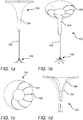
- Fig. 1 a and 1 b generally illustrates a system 100 comprising a brain interaction apparatus 102 and a cranial anchor 104 for providing filaments 106 into a brain such that measurement data or biological samples can be collected or such that a medical substance can be injected with a high degree of location accuracy.
- the cranial anchor 104 is illustrated in isolation.
- the system 100 may be applied by providing an aperture in a skull and thereafter insert the cranial anchor 104 into the hole.
- the cranial anchor 104 may be provided with a flange that rests against the skull when the cranial anchor is inserted.
- the cranial anchor may be rotationally symmetric and have side walls sloping inwards, as illustrated.
- grooves 108 may be provided in the cranial anchor. These grooves 108 may in a distal end of the cranial anchor be aligned with launching channels of the brain interaction apparatus 102 such that the filaments may smoothly be transferred from the cranial anchor to the brain interaction apparatus.
- the launcher position indicator may be achieved in different ways. It may be achieved mechanically by having a recess provided in the brain invasive launcher 102 and a protrusion in the cranial anchor 104, or vice versa, such that a sound is formed such that in turn that an operator is notified acoustically and/or tactically that the brain invasive launcher is correctly provided in the cranial anchor 104. After having made sure that the brain invasive launcher 102 is correctly mounted with respect to the cranial anchor 104 a location of a distal end of the brain invasive launcher 102 can be determined with high degree of accuracy.
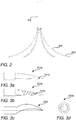
- each of the filaments are provided with steering tips 200.
- the steering tips 200 are designed to be rotationally asymmetrical, which has the effect that they move into the brain along a preset trajectory.
- the steering tips are exchangeable, which means e.g. that if a sharp trajectory is to prefer, i.e. a path having a high degree of curvature, a steering tip with a palpable rotational asymmetry is chosen.
- the steering tips 200 may come in different designs and shapes.
- a steering tip 200a according to a first example may have a distal end being offset with respect to a longitudinal center axis and be provided with one aperture, such as a micro pore, for injecting substances into the brain or for receiving a biological sample e.g. in the form of a suspension or other fluid or semi-fluid containing biological material.
- a steering tip 200b according to a second example is illustrated in a steering tip 200b according to a second example.
- the steering tip 200b is provided with a plurality of apertures 202b, such as micro-pores, such that biological material can be gathered quicker or such that substances can be injected over a larger area at the same time.
- a plurality of apertures 202b such as micro-pores
- an advantage of having the plurality of apertures is that a flow may be distributed over a larger area, which makes higher flow rates possible.
- another positive effect of having the flow distributed over a larger area is that a risk that the tissue is damaged can be reduced.
- a steering tip 200c is illustrated.
- the steering tip 200c according to the third example is not provided with a distal end offset a longitudinal center axis, but instead being curved such that when being fed into the brain curvature will give rise to that the filament to which the steering tip is attached moves along a trajectory. Thus, providing for that the filament is following the trajectory does not require the steering tip to be placed off-set with respect to the longitudinal center axis.
- a top view of a steering tip 200d according to a fourth example is illustrated. As the steering tips 200a, 200b according to the first and second examples, a distal end is offset a longitudinal center axis.
- the apertures may be micro-pores.
- Micro-pores used for delivering substances may be in a range 0.5 ⁇ m to 2 ⁇ m, and micro-pores used for collecting biological samples may be in a range 2 ⁇ m to 30 ⁇ m. Further, in order to provide for that the micro-pores for collecting are at reduced risk of being clogged these may have an anti-clogging design.
- micro-pores that are fabricated provides an advantage compared to e.g. porous polysulfane in that shape and size can be precisely controlled, which in turn provides for that injecting substances can be made with a high degree of accuracy.
- the filaments can reach locations of the brain with high accuracy launching channels 400 of the brain invasive launcher 102 can have exit holes 402 at well-defined angles and directed in chosen directions, as illustrated in fig 4a and 4b .
- Fig 5 schematically illustrates an example of how trajectories along which the filaments are inserted can be controlled. After having placed the brain invasive launcher 102 in the cranial anchor (not shown in fig 5 ) the filaments are fed into the brain, and due to the rotational asymmetry of the steering tips the filaments will move along well defined trajectories.
- the first filament may be rotated a pre-set number of degrees in a first rotation location 504a such that the path 500a is changed.
- a path 500b of a second filament to reach a second location 502b may be changed by being rotated in a second rotation location 504b.
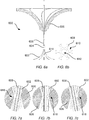
- Fig 6a illustrates an example of a system 600 for providing filaments 602 into the brain, wherein the system comprises a brain invasive launcher 604 connected to a cranial anchor 606 similar to the system 100 illustrated in fig 1 a and 1 b.
- the brain invasive launcher 604 is combined with a multi-lumen stylet 608, further illustrated in fig 6b , such that the filaments can be fed into grooves 610, or other types of channels, of the multi-lumen stylet as the brain invasive launcher 604 and the multi-lumen stylet 608 are fed into the brain.
- a central channel 612 of the multi-lumen stylet 608 may be provided for a central filament 614.
- the central filament may be of a different type than the other filaments 602.
- the central filament 614 may be a filament configured for gathering biological material and the other filaments 602 may be electrodes for collecting electric impulse data.
- the central channel 612 may also be used in systems without the multi-lumen stylet 608, such as the system 100 illustrated in fig 1 a and 1 b.
- the central filament 614 and the central channel 612 does not necessarily have to be placed centrally, but may in other embodiments than the one illustrated in fig 6a be placed in a non-central location.
- several channels and filaments like the central channel 612 and the central filament 614 may be used as well.
- a narrowed section 616 may be provided in the cranial anchor 606, as illustrated in fig 7a-c .
- the narrowed section 616 may also serve as a pivotal point for the multi-lumen stylet as illustrated in fig 7a-c .
- the multi-lumen stylet 608 may after the filaments 602 have been introduced be removed by carefully withdrawing the multi-lumen stylet 608 out from the brain via the cranial anchor 606 or, alternatively, the multi-lumen stylet 608 may be left in situ. Still an option is to partly remove the multi-lumen stylet, that is, withdrawing part of the multi-lumen stylet and leaving part of multi-lumen stylet in situ.
- multi-lumen stylet 608 provided with individual grooves, or other channels, for the filaments 602 reduces a risk that the filaments stuck when introducing or removing these compared to when one and the same channel is used for multiple filaments.
- the different parts of the systems may come in different sizes and shapes.
- a child skull may require a small cranial anchor, in order to reach deep into the brain an elongated brain invasive launcher may be needed, in order to collect measurement data in the form of electric pulses filaments in the form of electrodes may be needed, in order to be able to follow a set path in the brain a steering tip with a rotational asymmetry making it possible to closely follow this set path may be chosen, etc.
- having a modular system like the systems 100, 600 illustrated in fig 1a-b and fig 6a , makes it possible to provide a high degree of individual adjustment.
- Both the systems 100, 600 illustrated in fig 1 and fig 6 may form part of a system for determining a setup for collection of biological material, and/or a setup for collection of measurement data, and/or a setup of injection of at least one substance in a subsequent step.
- the system may comprise a data receiving unit configured to receive the measurement data collected by the at least one of the plurality of filaments, and a data storing unit configured to store the measurement data received by the data receiving unit, and a data analyzing unit configured to analyze the measurement data in order to determine the setup for collection of biological material, and/or a setup for collection of measurement data, and/or a setup for injection of at least one substance.
- the set-up may in this context be related to any information directly or indirectly related to when, where and how collection of biological material can be made in a subsequent step in order to achieve a better understanding of a condition of the brain, or directly or indirectly related to when, where and how collection of measurement data can be made in a subsequent step in order to achieve a better understanding of a condition of the brain, or directly or indirectly related to when, where and how injection of at least one substance can be made in a subsequent step in order improve the condition of the brain.
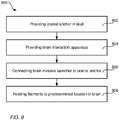
- Fig 8 generally illustrates a general method 800 for reaching a pre-determined location of the brain in order to be able to collect measurement data in order to e.g. making a diagnosis, or to collect a biological sample or to inject substances, may comprise providing a cranial anchor in the skull 802, providing a brain interaction apparatus comprising a brain invasive launcher and filaments 804, connecting the brain invasive launcher to the cranial anchor 806, and feeding the at least one of the filaments from the brain invasive launcher into the brain to the pre-determined location 808.
- Having the possibility to reach a location of the brain with high accuracy makes it possible to collect reliable data from different parts of the brain during a period of time, which in turn provides for that this data can be compared with other data collected from other brains in order to suggest a likely diagnosis or a treatment plan likely to work, but also in the case a tumor is present in the brain a likely placement of the tumor and a likely evolvement of the tumor.
- Fig 9 generally illustrates a method for providing decision support.
- the method 900 may comprise collecting measurement data from the brain 902, e.g. by using any of the systems or methods described herein, transferring location data and measurement data to a data processing device 904, comparing the location data and the measurement data with location data and measurement data collected from other brains 906, and providing a location data for subsequent measurement or providing a diagnosis or providing location data for injection 908.
- a system 1000 generally illustrated in fig 10 may be used.
- a system 1002 attached to the skull of a patient may be used.
- the system 1002 may comprise the systems 100, 600 illustrated in fig 1a-b and fig 6a in order to collect the location and measurement data.
- a data processing device 1006 e.g. a server.
- location data and measurement data collected from other brains can be downloaded and compared to the data collected from the brain.
- the data collected from other brains may be downloaded via a data communications network 1008 and the data collected from other brains may be stored on a data storage device 1010.
Landscapes
- Health & Medical Sciences (AREA)
- Life Sciences & Earth Sciences (AREA)
- Surgery (AREA)
- General Health & Medical Sciences (AREA)
- Animal Behavior & Ethology (AREA)
- Engineering & Computer Science (AREA)
- Biomedical Technology (AREA)
- Heart & Thoracic Surgery (AREA)
- Veterinary Medicine (AREA)
- Public Health (AREA)
- Molecular Biology (AREA)
- Pathology (AREA)
- Medical Informatics (AREA)
- Physics & Mathematics (AREA)
- Biophysics (AREA)
- Nuclear Medicine, Radiotherapy & Molecular Imaging (AREA)
- Neurology (AREA)
- Oral & Maxillofacial Surgery (AREA)
- Physiology (AREA)
- Neurosurgery (AREA)
- Psychology (AREA)
- Vascular Medicine (AREA)
- Anesthesiology (AREA)
- Hematology (AREA)
- Media Introduction/Drainage Providing Device (AREA)
- Magnetic Resonance Imaging Apparatus (AREA)
Abstract
Description
- The inventive concept described herein generally relates to the field of brain interaction apparatuses and, more particularly, to a brain interaction apparatus comprising a plurality of filaments, to cranial anchors, and to related systems and methods.
- Catheters have been used for many years to deliver therapeutic agents to patients. In many instances, catheters are implanted in patients that have been diagnosed with diseases that require long-term therapeutic treatment, for example brain tumors. When treating these types of diseases, a need arises to deliver therapeutic drugs to multiple locations simultaneously. Current technology requires the use of multiple separate catheters and pumps to ensure the equal delivery of therapeutics to the tumor and the outlying tissues.
- Additionally, in some cases it is necessary to obtain several samples over a period of time in order to determine the type of disease and monitor its progress. Such surgical procedures carry an intrinsically high level of risk of infection and hemorrhage.
- An example of a catheter assembly aimed at reducing the risk of hemorrhage or tissue trauma is disclosed in US application
US2011/0224607A . The catheter assembly comprises a first catheter including a wall with an inner surface, and a second catheter connected to the wall of the first catheter and disposed outward of the inner surface of the wall. -
PCT application WO2014170338 discloses another type of a surgical instrument used for invasive maneuvers in the body of a patient. The multi-cannula surgical instrument disclosed in this document functions either as an electrocautery instrument or as a safety needle. The multi-cannula surgical instrument comprises a rigid outer cannula, and an inner cannula. The inner cannula further comprises one or more first inner ducts and one or more first flow-through orifices near a distal tip of the inner cannula. - Further, in
US 2010/0222668A1 a catheter system adapted for navigating, guiding and implanting a catheter or a plurality of catheters in a spatially defined implantation within the tissue of a patient is provided. The system can include a tissue navigation system and a probe to inform the navigation system to guide emplacement of the catheters within a target tissue. The probe can provide images, such as fiber-optic visual images, or ultrasound images, or can provide radiolocation data, to guide the catheter emplacement. The catheters supply a pressurized liquid including a bioactive agent, such as can be used in the treatment of cancer, for example 1231-or 1251-IUDR. The system and methods provided can be used in the treatment of locally advanced tumors, such as cancers of the brain, head or neck, esophagus, prostate, ovary, liver, pancreas, bladder or rectum. - However, there exists a significant need for improved techniques related to brain interaction apparatuses in order to minimize the invasiveness of procedures in the brain of a patient. Further, there is a need for increased accuracy of such procedures in order to gain a better understanding of diseases and ultimately select an appropriate treatment. Still further, there is a need to improve brain interaction apparatuses with respect to size and ease of application to the skull and brain of a patient.
- It is an object of the present inventive concept to mitigate, alleviate or eliminate one or more of the above-identified deficiencies in the art and disadvantages singly or in combination. According to a first aspect of the inventive concept, these and other objects are achieved in full, or at least in part, by a brain interaction apparatus, comprising a plurality of filaments; a brain invasive launcher having a plurality of launching channels extending in a longitudinal direction between a proximal end and a distal end thereof, each launching channel being configured for holding a filament moveably arranged therein, the filament being one of the plurality of filaments; wherein at least one of the plurality of filaments is provided with a steering tip affixed to a distal end thereof, wherein the steering tip comprises a portion tapering in a longitudinal direction of the at least one of the plurality of filaments thereby narrowing toward a distal end of the steering tip, the tapered portion being rotationally asymmetrical about a longitudinal axis of the at least one of the plurality of filaments.
- The distal end of the steering tip may be offset from the longitudinal axis of the at least one of the plurality of filaments.
- Further, the brain invasive launcher may comprise a launcher position indicator configured to determine a location of the brain invasive launcher in a brain of a subject.
- The at least one of the plurality of filaments may be configured to be in an installation state, in which the filament is housed in the launching channel, and a working state, in which the filament is extended beyond the distal end of the brain invasive launcher when the same is in a fixed position.
- The at least one of the plurality of filaments may comprise a plurality of apertures.
- The steering tip may comprise a steering tip position indicator configured to determine a location of the steering tip and/or the at least one of the plurality of filaments in a brain of a subject.
- The at least one of the plurality of filaments may be configured to collect measurement data.
- The at least one of the plurality of filaments may be an optical fibre.
- The at least one of the plurality of filaments may be an electrical wire.
- The brain interaction apparatus may further comprise a multi-lumen stylet connected to the brain invasive launcher, wherein the multi-lumen stylet comprises a plurality of channels configured for holding the plurality of filaments, and wherein the plurality of channels is aligned with the plurality of launching channels of the brain invasive launcher.
- According to a second aspect it is provided a cranial anchor for a brain interaction apparatus according to the first aspect, the cranial anchor being configured to be secured to a skull of a subject, the cranial anchor comprising
a proximal end forming an outer flange; an elongated distal end for inserting into a skull aperture, wherein an axial lumen is provided, the axial lumen being tapered in a longitudinal direction of the cranial anchor and narrowing toward the distal end; wherein the proximal end comprises at least one groove extending from the circumference of the outer flange toward a central axis of the cranial anchor, and wherein the axial lumen is configured for receiving and guiding the brain invasive launcher, and wherein the axial lumen provides a pivot point for directing the brain invasive launcher. - The elongated distal end may be provided with a narrowed section having a diameter adjusted to a diameter of the multi-stylet such that the plurality of filaments is brought into the channels.
- The narrowed section function may provide a pivotal point for the multi-stylet.
- According to a third aspect it is provided a system comprising; a brain interaction apparatus according to the first aspect; a cranial anchor according to the second aspect; a data receiving unit configured to receive measurement data collected by the at least one of the plurality of filaments; a data storing unit configured to store the measurement data received by the data receiving unit; a data analyzing unit configured to analyze the measurement data in order to determine a setup of collection of biological material, and/or a setup of collection of data, and/or a setup of injection of at least one substance.
- According to a fourth aspect it is provided a method comprising providing a cranial anchor according to the second aspect inserted in a skull of a subject; providing a brain interaction apparatus according to the first aspect; connecting the brain invasive launcher to the cranial anchor, thereby having at least the brain invasive launcher entering the brain of the subject; feeding at least one of the plurality of filaments beyond the distal end of the brain invasive launcher in a trajectory in relation to the brain invasive launcher while the same remains in a fixed position, thereby reaching a pre-determined location of the brain.
- The step of extending at least one of the plurality of filaments may comprise rotating the at least one of the plurality of filaments along its longitudinal axis in order to adjust the trajectory and arrive at the pre-determined location.
- The method may further comprise collecting data and/or biological material associated with the pre-determined location via the at least one of the plurality of filaments, and analyzing the collected data and/or biological material in order to determine a setup of the collection of biological material, and/or a setup of the collection of data, and/or a setup of the injection of the least one substance.
- The step of collecting data and/or biological material may be performed during a collection phase being at least 24 hours.
- The method may further comprise injecting at least one substance into the brain at one or more injecting locations via the at least one of the plurality of filaments.
- The step of injecting at least one substance may be performed during an injection phase being at least 24 hours.
- The method may further comprise filling an upper portion of the axial lumen with an inert, resilient material in order to seal the brain interaction apparatus from an external environment.
- According to a fifth aspect it is provided a kit of parts comprising: a brain interaction apparatus according to the first aspect; wherein the kit of parts comprises at least two types of filaments, and wherein the kit of parts comprises at least two types of steering tips.
- The kit of parts may further comprise at least two types of cranial anchors according to the second aspect.
- According to a sixth aspect it is provided a method for providing decision support in diagnosing or treating a brain disease, the method comprising collecting measurement data from at least one location in a brain, transferring location data and the measurement data to a data processing device connected to a data storage device, wherein the data storage device comprises a time series of location data and measurement data collected from other brains, comparing the location data and the measurement data with the time series of location data and measurement data collected from other brains, based on the comparison, providing location data for a subsequent measurement, or providing a diagnosis, or providing location data for injection of at least one substance.
- The step of collecting measurement data may be performed during a period of at least 24 hours.
- A feature described in relation to one aspect may also be incorporated in other aspects, and the advantage of the feature is applicable to all aspects in which it is incorporated.
- Other objectives, features and advantages of the present inventive concept will appear from the following detailed disclosure, from the attached claims as well as from the drawings.
- Generally, all terms used in the claims are to be interpreted according to their ordinary meaning in the technical field, unless explicitly defined otherwise herein. Further, the use of terms "first", "second", and "third", and the like, herein do not denote any order, quantity, or importance, but rather are used to distinguish one element from another. All references to "a/an/the [element, device, component, means, step, etc]" are to be interpreted openly as referring to at least one instance of said element, device, component, means, step, etc., unless explicitly stated otherwise. The steps of any method disclosed herein do not have to be performed in the exact order disclosed, unless explicitly stated.
- The above, as well as additional objects, features and advantages of the present inventive concept, will be better understood through the following illustrative and non-limiting detailed description of different embodiments of the present inventive concept, with reference to the appended drawings, wherein:
-
FIG. 1 a schematically illustrates a side view of a brain interaction apparatus and a cranial anchor; -
FIG. 1b schematically illustrates a perspective view of a brain interaction apparatus and a cranial anchor; -
FIG. 1c schematically illustrates a top view of cranial anchor; -
FIG. 1d schematically illustrates a side view of a cranial anchor; -
FIG. 2 schematically illustrates a brain interaction apparatus; -
FIG. 3a schematically illustrates a side view of a steering tip; -
FIG. 3b schematically illustrates a side view of a steering tip; -
FIG. 3c schematically illustrates a side view of a steering tip; -
FIG. 3d schematically illustrates a top view of a steering tip; -
FIG. 4a schematically illustrates a side view of a brain invasive launcher; -
FIG. 4b schematically illustrates a side view of a brain invasive launcher; -
FIG. 5 schematically illustrates a two-dimensional representation of a plurality of filaments and respective trajectories; -
Fig 6a schematically illustrates a cross-sectional view of another example of a combination of a brain interaction apparatus and a cranial anchor; -
Fig 6b illustrates a cross-section of a multi-lumen stylet; -
Fig 7a, b and c illustrates a narrowed section of the cranial anchor offig 6 in further detail; -
Fig 8 is a flow chart illustrating a method for reaching a pre-determined location of a brain by using a brain interaction apparatus and a cranial anchor; -
Fig 9 is a flowchart illustrating a method for assisted decision support; and -
Fig 10 generally illustrates a system for implanting the method according to the flowchart offig 9 . -
Fig. 1 a and 1 b generally illustrates asystem 100 comprising abrain interaction apparatus 102 and acranial anchor 104 for providingfilaments 106 into a brain such that measurement data or biological samples can be collected or such that a medical substance can be injected with a high degree of location accuracy. Infig. 1c and 1d , thecranial anchor 104 is illustrated in isolation. - The
system 100 may be applied by providing an aperture in a skull and thereafter insert thecranial anchor 104 into the hole. In order to be securely attached to the skull thecranial anchor 104 may be provided with a flange that rests against the skull when the cranial anchor is inserted. Further, the cranial anchor may be rotationally symmetric and have side walls sloping inwards, as illustrated. An advantage of these features is that thefilaments 106 can be gradually redirected approximately 90 degrees from being fed in parallel with a skull surface outside the skull to being fed in parallel with a normal of the skull surface inside the skull. This in turn implies that the filaments may lay close to the skull when measurement data or samples are collected or when substance is injected, which both reduces a risk that the filaments are unintentionally displaced and increases the comfort of a patient. - In order to guide the
filaments grooves 108 may be provided in the cranial anchor. Thesegrooves 108 may in a distal end of the cranial anchor be aligned with launching channels of thebrain interaction apparatus 102 such that the filaments may smoothly be transferred from the cranial anchor to the brain interaction apparatus. - In order to make sure that the pre-determined location can be reached with a high degree of accuracy a launcher position indicator may be used. The launcher position indicator may be achieved in different ways. It may be achieved mechanically by having a recess provided in the brain
invasive launcher 102 and a protrusion in thecranial anchor 104, or vice versa, such that a sound is formed such that in turn that an operator is notified acoustically and/or tactically that the brain invasive launcher is correctly provided in thecranial anchor 104. After having made sure that the braininvasive launcher 102 is correctly mounted with respect to the cranial anchor 104 a location of a distal end of the braininvasive launcher 102 can be determined with high degree of accuracy. - As illustrated in
fig 2 , in order to be able to steer thefilaments 106 to final positions within the brain each of the filaments are provided withsteering tips 200. Thesteering tips 200 are designed to be rotationally asymmetrical, which has the effect that they move into the brain along a preset trajectory. In order to be able to precisely guide the filaments into the brain the steering tips are exchangeable, which means e.g. that if a sharp trajectory is to prefer, i.e. a path having a high degree of curvature, a steering tip with a palpable rotational asymmetry is chosen. - As illustrated in
fig 3a to 3d , thesteering tips 200 may come in different designs and shapes. As illustrated infig 3a , asteering tip 200a according to a first example may have a distal end being offset with respect to a longitudinal center axis and be provided with one aperture, such as a micro pore, for injecting substances into the brain or for receiving a biological sample e.g. in the form of a suspension or other fluid or semi-fluid containing biological material. Infig 3b asteering tip 200b according to a second example is illustrated. Unlike thesteering tip 200a according to the first example, thesteering tip 200b is provided with a plurality ofapertures 202b, such as micro-pores, such that biological material can be gathered quicker or such that substances can be injected over a larger area at the same time. In addition, an advantage of having the plurality of apertures is that a flow may be distributed over a larger area, which makes higher flow rates possible. Further, another positive effect of having the flow distributed over a larger area is that a risk that the tissue is damaged can be reduced. - In
fig 3c asteering tip 200c is illustrated. Unlike thesteering tips steering tip 200c according to the third example is not provided with a distal end offset a longitudinal center axis, but instead being curved such that when being fed into the brain curvature will give rise to that the filament to which the steering tip is attached moves along a trajectory. Thus, providing for that the filament is following the trajectory does not require the steering tip to be placed off-set with respect to the longitudinal center axis. Infig 3d a top view of asteering tip 200d according to a fourth example is illustrated. As thesteering tips - As mentioned above, the apertures may be micro-pores. Micro-pores used for delivering substances may be in a range 0.5 µm to 2 µm, and micro-pores used for collecting biological samples may be in a range 2 µm to 30 µm. Further, in order to provide for that the micro-pores for collecting are at reduced risk of being clogged these may have an anti-clogging design.
- Having micro-pores that are fabricated provides an advantage compared to e.g. porous polysulfane in that shape and size can be precisely controlled, which in turn provides for that injecting substances can be made with a high degree of accuracy.
- In order to provide for that the filaments can reach locations of the brain with high
accuracy launching channels 400 of the braininvasive launcher 102 can haveexit holes 402 at well-defined angles and directed in chosen directions, as illustrated infig 4a and 4b . -
Fig 5 schematically illustrates an example of how trajectories along which the filaments are inserted can be controlled. After having placed the braininvasive launcher 102 in the cranial anchor (not shown infig 5 ) the filaments are fed into the brain, and due to the rotational asymmetry of the steering tips the filaments will move along well defined trajectories. - In order to change a
path 500a of a first filament to reach afirst location 502a the first filament may be rotated a pre-set number of degrees in afirst rotation location 504a such that thepath 500a is changed. In the same manner, apath 500b of a second filament to reach asecond location 502b may be changed by being rotated in asecond rotation location 504b. -
Fig 6a illustrates an example of asystem 600 for providingfilaments 602 into the brain, wherein the system comprises a braininvasive launcher 604 connected to acranial anchor 606 similar to thesystem 100 illustrated infig 1 a and 1 b. However, unlike thesystem 100, the braininvasive launcher 604 is combined with amulti-lumen stylet 608, further illustrated infig 6b , such that the filaments can be fed intogrooves 610, or other types of channels, of the multi-lumen stylet as the braininvasive launcher 604 and themulti-lumen stylet 608 are fed into the brain. - Further, a
central channel 612 of themulti-lumen stylet 608 may be provided for acentral filament 614. The central filament may be of a different type than theother filaments 602. For instance, thecentral filament 614 may be a filament configured for gathering biological material and theother filaments 602 may be electrodes for collecting electric impulse data. Even though only illustrated together with themulti-lumen stylet 608, thecentral channel 612 may also be used in systems without themulti-lumen stylet 608, such as thesystem 100 illustrated infig 1 a and 1 b. Further, thecentral filament 614 and thecentral channel 612 does not necessarily have to be placed centrally, but may in other embodiments than the one illustrated infig 6a be placed in a non-central location. In addition, even though onecentral channel 612 andcentral filament 614 are illustrated, several channels and filaments like thecentral channel 612 and thecentral filament 614 may be used as well. - In order to provide for that the
filaments 602 are properly fed into thegrooves 610 of the multi-lumen stylet 608 a narrowedsection 616 may be provided in thecranial anchor 606, as illustrated infig 7a-c . In addition to pushing thefilaments 602 into thegrooves 610 the narrowedsection 616 may also serve as a pivotal point for the multi-lumen stylet as illustrated infig 7a-c . By having the possibility to pivot the multi-lumen stylet around the narrowed section 616 a number of different path options can be increased. Even though only illustrated for thesystem 600 comprising themulti-lumen stylet 608 the concept of having the narrowedsection 616 such that pivoting is made possible is also applicable to for instance thesystem 100 illustrated infig 1a-b . - The
multi-lumen stylet 608 may after thefilaments 602 have been introduced be removed by carefully withdrawing themulti-lumen stylet 608 out from the brain via thecranial anchor 606 or, alternatively, themulti-lumen stylet 608 may be left in situ. Still an option is to partly remove the multi-lumen stylet, that is, withdrawing part of the multi-lumen stylet and leaving part of multi-lumen stylet in situ. - Having the
multi-lumen stylet 608 provided with individual grooves, or other channels, for thefilaments 602 reduces a risk that the filaments stuck when introducing or removing these compared to when one and the same channel is used for multiple filaments. - In order to be able to individually adapt the
system 600, as well as thesystem 100, the different parts of the systems may come in different sizes and shapes. For instance, a child skull may require a small cranial anchor, in order to reach deep into the brain an elongated brain invasive launcher may be needed, in order to collect measurement data in the form of electric pulses filaments in the form of electrodes may be needed, in order to be able to follow a set path in the brain a steering tip with a rotational asymmetry making it possible to closely follow this set path may be chosen, etc. Thus, having a modular system, like thesystems fig 1a-b andfig 6a , makes it possible to provide a high degree of individual adjustment. - Both the
systems fig 1 andfig 6 , respectively, may form part of a system for determining a setup for collection of biological material, and/or a setup for collection of measurement data, and/or a setup of injection of at least one substance in a subsequent step. In addition to the brain interaction apparatus and the cranial anchor, the system may comprise a data receiving unit configured to receive the measurement data collected by the at least one of the plurality of filaments, and a data storing unit configured to store the measurement data received by the data receiving unit, and a data analyzing unit configured to analyze the measurement data in order to determine the setup for collection of biological material, and/or a setup for collection of measurement data, and/or a setup for injection of at least one substance. The set-up may in this context be related to any information directly or indirectly related to when, where and how collection of biological material can be made in a subsequent step in order to achieve a better understanding of a condition of the brain, or directly or indirectly related to when, where and how collection of measurement data can be made in a subsequent step in order to achieve a better understanding of a condition of the brain, or directly or indirectly related to when, where and how injection of at least one substance can be made in a subsequent step in order improve the condition of the brain. -
Fig 8 generally illustrates ageneral method 800 for reaching a pre-determined location of the brain in order to be able to collect measurement data in order to e.g. making a diagnosis, or to collect a biological sample or to inject substances, may comprise providing a cranial anchor in theskull 802, providing a brain interaction apparatus comprising a brain invasive launcher andfilaments 804, connecting the brain invasive launcher to thecranial anchor 806, and feeding the at least one of the filaments from the brain invasive launcher into the brain to thepre-determined location 808. - Having the possibility to reach a location of the brain with high accuracy makes it possible to collect reliable data from different parts of the brain during a period of time, which in turn provides for that this data can be compared with other data collected from other brains in order to suggest a likely diagnosis or a treatment plan likely to work, but also in the case a tumor is present in the brain a likely placement of the tumor and a likely evolvement of the tumor.
-
Fig 9 generally illustrates a method for providing decision support. Themethod 900 may comprise collecting measurement data from thebrain 902, e.g. by using any of the systems or methods described herein, transferring location data and measurement data to adata processing device 904, comparing the location data and the measurement data with location data and measurement data collected fromother brains 906, and providing a location data for subsequent measurement or providing a diagnosis or providing location data forinjection 908. - In order to implement the
method 900 illustrated infig 9 , asystem 1000 generally illustrated infig 10 may be used. In order to collect the location data and the measurement data asystem 1002 attached to the skull of a patient may be used. Thesystem 1002 may comprise thesystems fig 1a-b andfig 6a in order to collect the location and measurement data. - After having collected the data this can be sent to a
data processing device 1006, e.g. a server. In order to analyze the data collected from the brain, location data and measurement data collected from other brains can be downloaded and compared to the data collected from the brain. The data collected from other brains may be downloaded via adata communications network 1008 and the data collected from other brains may be stored on adata storage device 1010. - The inventive concept has mainly been described above with reference to a few embodiments. However, as is readily appreciated by a person skilled in the art, other embodiments than the ones disclosed above are equally possible within the scope of the inventive concept, as defined by the appended patent claims.
Claims (25)
- A brain interaction apparatus, comprising
a plurality of filaments;
a brain invasive launcher having a plurality of launching channels extending in a longitudinal direction between a proximal end and a distal end thereof, each launching channel being configured for holding a filament moveably arranged therein, the filament being one of the plurality of filaments;
wherein at least one of the plurality of filaments is provided with a steering tip affixed to a distal end thereof, wherein the steering tip comprises a portion tapering in a longitudinal direction of the at least one of the plurality of filaments thereby narrowing toward a distal end of the steering tip, the tapered portion being rotationally asymmetrical about a longitudinal axis of the at least one of the plurality of filaments. - The brain interaction apparatus according to claim 1, wherein the distal end of the steering tip is offset from the longitudinal axis of the at least one of the plurality of filaments.
- The brain interaction apparatus according to any one of the preceding claims, wherein the brain invasive launcher comprises a launcher position indicator configured to determine a location of the brain invasive launcher in a brain of a subject.
- The brain interaction apparatus according to any one of the preceding claims, wherein the at least one of the plurality of filaments is configured to be in an installation state, in which the filament is housed in the launching channel, and a working state, in which the filament is extended beyond the distal end of the brain invasive launcher when the same is in a fixed position.
- The brain interaction apparatus according to any one of the preceding claims, wherein the at least one of the plurality of filaments comprises a plurality of apertures.
- The brain interaction apparatus according to any one of the preceding claims, wherein the steering tip comprises a steering tip position indicator configured to determine a location of the steering tip and/or the at least one of the plurality of filaments in a brain of a subject.
- The brain interaction apparatus according to any one of the preceding claims, wherein the at least one of the plurality of filaments is configured to collect measurement data.
- The brain interaction apparatus according to claim 7, wherein the at least one of the plurality of filaments is an optical fibre.
- The brain interaction apparatus according to claim 7, wherein the at least one of the plurality of filaments is an electrical wire.
- The brain interaction apparatus according to any one of the preceding claims, further comprising a multi-lumen stylet connected to the brain invasive launcher, wherein the multi-lumen stylet comprises a plurality of channels configured for holding the plurality of filaments, and wherein the plurality of channels is aligned with the plurality of launching channels of the brain invasive launcher.
- A cranial anchor for a brain interaction apparatus according to any one of claims 1 to 10, the cranial anchor being configured to be secured to a skull of a subject, the cranial anchor comprising
a proximal end forming an outer flange;
an elongated distal end for inserting into a skull aperture,
wherein an axial lumen is provided, the axial lumen being tapered in a longitudinal direction of the cranial anchor and narrowing toward the distal end;
wherein the proximal end comprises at least one groove extending from the circumference of the outer flange toward a central axis of the cranial anchor, and wherein the axial lumen is configured for receiving and guiding the brain invasive launcher, and wherein the axial lumen provides a pivot point for directing the brain invasive launcher. - The cranial anchor according to claim 11 for a brain interaction apparatus according to claim 10, wherein the elongated distal end is provided with a narrowed section having a diameter adjusted to a diameter of the multi-stylet such that the plurality of filaments is brought into the channels.
- The cranial anchor according to claim 12, wherein the narrowed section function provides a pivotal point for the multi-stylet.
- A system comprising;
a brain interaction apparatus according to any one of the claims 7 to 10;
a cranial anchor according to any one of the claims 11 to 13;
a data receiving unit configured to receive measurement data collected by the at least one of the plurality of filaments;
a data storing unit configured to store the measurement data received by the data receiving unit;
a data analyzing unit configured to analyze the measurement data in order to determine a setup of collection of biological material, and/or a setup of collection of data, and/or a setup of injection of at least one substance. - A method comprising
providing a cranial anchor according to any one of the claims 11 to 13 inserted in a skull of a subject;
providing a brain interaction apparatus according to any one of claims 1 to 10;
connecting the brain invasive launcher to the cranial anchor, thereby having at least the brain invasive launcher entering the brain of the subject;
feeding at least one of the plurality of filaments beyond the distal end of the brain invasive launcher in a trajectory in relation to the brain invasive launcher while the same remains in a fixed position, thereby reaching a pre-determined location of the brain. - The method according to claim 15, wherein extending at least one of the plurality of filaments comprises rotating the at least one of the plurality of filaments along its longitudinal axis in order to adjust the trajectory and arrive at the pre-determined location.
- The method according to claim 15 or 16, further comprising collecting data and/or biological material associated with the pre-determined location via the at least one of the plurality of filaments, and analyzing the collected data and/or biological material in order to determine a setup of the collection of biological material, and/or a setup of the collection of data, and/or a setup of the injection of the least one substance.
- The method according to claim 17, wherein the step of collecting data and/or biological material is performed during a collection phase being at least 24 hours.
- The method according to any one of claims 15 to 17, further comprising injecting at least one substance into the brain at one or more injecting locations via the at least one of the plurality of filaments.
- The method according to claim 19, wherein the step of injecting at least one substance is performed during an injection phase being at least 24 hours.
- The method according to any one of claims 15 to 18, further comprising filling an upper portion of the axial lumen with an inert, resilient material in order to seal the brain interaction apparatus from an external environment.
- A kit of parts comprising:a brain interaction apparatus according to any one of claims 1 to 10;wherein the kit of parts comprises at least two types of filaments, and wherein the kit of parts comprises at least two types of steering tips.
- The kit of parts according to claim 22, further comprising at least two types of cranial anchors according to any one of claims 11 to 13.
- A method for providing decision support in diagnosing or treating a brain disease, the method comprising
collecting measurement data from at least one location in a brain, transferring location data and the measurement data to a data processing device connected to a data storage device, wherein the data storage device comprises a time series of location data and measurement data collected from other brains,
comparing the location data and the measurement data with the time series of location data and measurement data collected from other brains,
based on the comparison, providing location data for a subsequent measurement, or providing a diagnosis, or providing location data for injection of at least one substance. - The method according to claim 24, wherein the step of collecting measurement data is performed during a period of at least 24 hours.
Priority Applications (2)
| Application Number | Priority Date | Filing Date | Title |
|---|---|---|---|
| EP17176002.8A EP3415106B1 (en) | 2017-06-14 | 2017-06-14 | Brain interaction apparatus, cranial anchor, and related systems |
| US15/994,305 US11931160B2 (en) | 2017-06-14 | 2018-05-31 | Brain interaction apparatus, cranial anchor, and related systems and methods |
Applications Claiming Priority (1)
| Application Number | Priority Date | Filing Date | Title |
|---|---|---|---|
| EP17176002.8A EP3415106B1 (en) | 2017-06-14 | 2017-06-14 | Brain interaction apparatus, cranial anchor, and related systems |
Publications (2)
| Publication Number | Publication Date |
|---|---|
| EP3415106A1 true EP3415106A1 (en) | 2018-12-19 |
| EP3415106B1 EP3415106B1 (en) | 2022-08-03 |
Family
ID=59077860
Family Applications (1)
| Application Number | Title | Priority Date | Filing Date |
|---|---|---|---|
| EP17176002.8A Active EP3415106B1 (en) | 2017-06-14 | 2017-06-14 | Brain interaction apparatus, cranial anchor, and related systems |
Country Status (2)
| Country | Link |
|---|---|
| US (1) | US11931160B2 (en) |
| EP (1) | EP3415106B1 (en) |
Families Citing this family (2)
| Publication number | Priority date | Publication date | Assignee | Title |
|---|---|---|---|---|
| WO2021152100A1 (en) * | 2020-01-30 | 2021-08-05 | INSERM (Institut National de la Santé et de la Recherche Médicale) | Insertion device and assembly comprising such insertion device and a flexible implantable strip |
| US12274587B2 (en) * | 2022-08-19 | 2025-04-15 | Clearpoint Neuro, Inc. | Method for bone collision detection using a stereotactic image-guided navigation system |
Citations (8)
| Publication number | Priority date | Publication date | Assignee | Title |
|---|---|---|---|---|
| US20060015067A1 (en) * | 2004-07-19 | 2006-01-19 | Bates Mark C | Apparatus and methods for treating tissue using passive injection systems |
| WO2009047494A1 (en) * | 2007-10-08 | 2009-04-16 | Renishaw Plc | Apparatus for stereotactic neurosurgery |
| US20100222668A1 (en) | 2007-03-20 | 2010-09-02 | Dalke William D | Guidance and implantation of catheters |
| US20110224607A1 (en) | 2010-03-10 | 2011-09-15 | The Cleveland Clinic Foundation | Catheter assembly |
| US20120245529A1 (en) * | 2009-12-11 | 2012-09-27 | Carag Ag | Anchoring device for a line in a skull bore hole |
| US20120316628A1 (en) * | 2011-06-08 | 2012-12-13 | Lopez Thomas P | Strain relieved lead routing in burr hole plug for deep brain stimulation |
| WO2014170338A1 (en) | 2013-04-17 | 2014-10-23 | Vesalius Medical Technologies Bvba | A multi-cannula surgical instrument |
| US20160346513A1 (en) * | 2015-05-26 | 2016-12-01 | Vanderbilt University | Surgical device tip with arc length varying curvature |
Family Cites Families (15)
| Publication number | Priority date | Publication date | Assignee | Title |
|---|---|---|---|---|
| DE4408108A1 (en) | 1994-03-10 | 1995-09-14 | Bavaria Med Tech | Catheter for injecting a fluid or a drug |
| US5441481A (en) | 1994-05-27 | 1995-08-15 | Mishra; Pravin | Microdialysis probes and methods of use |
| EP0967932B1 (en) * | 1996-11-19 | 2003-05-02 | Uroplasty, Inc. | Instrument for guiding delivery of injectable materials in treating urinary incontinence |
| US7025765B2 (en) * | 2000-03-31 | 2006-04-11 | Rita Medical Systems, Inc. | Tissue biopsy and treatment apparatus and method |
| GB0100247D0 (en) | 2001-01-05 | 2001-02-14 | Univ Dundee | Improved hypodermic needle and fluid injection device |
| US7604658B2 (en) * | 2004-05-04 | 2009-10-20 | Codman & Shurtleff, Inc. | Multiple lumen sensor attachment |
| US20070106143A1 (en) * | 2005-11-08 | 2007-05-10 | Flaherty J C | Electrode arrays and related methods |
| US9011319B2 (en) * | 2006-03-03 | 2015-04-21 | Axcess Instruments, Inc. | Conical laparoscopic apparatus for minimally invasive surgery |
| US8517976B2 (en) * | 2006-04-03 | 2013-08-27 | Helio Zapata | Abdominal insufflator and principal trocar-cannula device |
| WO2008020967A2 (en) | 2006-08-08 | 2008-02-21 | Peak Biosciences, Inc. | Catheter and array for anticancer therapy |
| US9339331B2 (en) * | 2008-12-29 | 2016-05-17 | St. Jude Medical, Atrial Fibrillation Division, Inc. | Non-contact electrode basket catheters with irrigation |
| US8374703B2 (en) * | 2009-01-26 | 2013-02-12 | Incube Labs, Llc | Method and apparatus for the detection of aberrant neural-electric activity |
| US10220124B2 (en) | 2009-02-27 | 2019-03-05 | Virginia Tech Intellectual Properties, Inc. | Fiber array for optical imaging and therapeutics |
| US8798722B2 (en) | 2009-02-27 | 2014-08-05 | Virginia Tech Intellectual Properties, Inc. | Fiber array for optical imaging and therapeutics |
| US9931046B2 (en) * | 2013-10-25 | 2018-04-03 | Ablative Solutions, Inc. | Intravascular catheter with peri-vascular nerve activity sensors |
-
2017
- 2017-06-14 EP EP17176002.8A patent/EP3415106B1/en active Active
-
2018
- 2018-05-31 US US15/994,305 patent/US11931160B2/en active Active
Patent Citations (8)
| Publication number | Priority date | Publication date | Assignee | Title |
|---|---|---|---|---|
| US20060015067A1 (en) * | 2004-07-19 | 2006-01-19 | Bates Mark C | Apparatus and methods for treating tissue using passive injection systems |
| US20100222668A1 (en) | 2007-03-20 | 2010-09-02 | Dalke William D | Guidance and implantation of catheters |
| WO2009047494A1 (en) * | 2007-10-08 | 2009-04-16 | Renishaw Plc | Apparatus for stereotactic neurosurgery |
| US20120245529A1 (en) * | 2009-12-11 | 2012-09-27 | Carag Ag | Anchoring device for a line in a skull bore hole |
| US20110224607A1 (en) | 2010-03-10 | 2011-09-15 | The Cleveland Clinic Foundation | Catheter assembly |
| US20120316628A1 (en) * | 2011-06-08 | 2012-12-13 | Lopez Thomas P | Strain relieved lead routing in burr hole plug for deep brain stimulation |
| WO2014170338A1 (en) | 2013-04-17 | 2014-10-23 | Vesalius Medical Technologies Bvba | A multi-cannula surgical instrument |
| US20160346513A1 (en) * | 2015-05-26 | 2016-12-01 | Vanderbilt University | Surgical device tip with arc length varying curvature |
Also Published As
| Publication number | Publication date |
|---|---|
| US11931160B2 (en) | 2024-03-19 |
| EP3415106B1 (en) | 2022-08-03 |
| US20180360367A1 (en) | 2018-12-20 |
Similar Documents
| Publication | Publication Date | Title |
|---|---|---|
| JP6983745B2 (en) | Cranial drill system | |
| US20080275466A1 (en) | Dual cannula system and method for using same | |
| EP2358428B1 (en) | Implant electrode and accessories for use in robotic surgery | |
| US20240156623A1 (en) | Directional stent for accessing extravascular spaces | |
| US12396750B2 (en) | Adjustable stepped cannula | |
| US20100318061A1 (en) | Catheter | |
| US20190314574A1 (en) | Devices and methods for percutaneous lung intratumoral therapy delivery | |
| JP2007503952A (en) | Method of using a deflectable medical therapy delivery device having a common lumen profile | |
| JP2010540202A (en) | Stereotaxic device | |
| US8083720B2 (en) | Device and method for delivering therapeutic agents to an area of the body | |
| JP2015523172A (en) | Microinfusion catheter | |
| EA027149B1 (en) | Steerable deflectors and methods of using same | |
| JP2012504997A (en) | catheter | |
| US11931160B2 (en) | Brain interaction apparatus, cranial anchor, and related systems and methods | |
| US20190038340A1 (en) | Radiofrequency cannula with fenestrated active tip | |
| US20260060719A1 (en) | Entry site tissue puncture system | |
| EP3585291B1 (en) | System for improving location accuracy of a radiofrequency ablation procedure via fiducial marking | |
| US20250213270A1 (en) | Stabilizing tissue access needle devices, systems and methods | |
| WO2023183630A1 (en) | Stabilizing tissue access needle devices, systems and methods | |
| US20100047210A1 (en) | Systems and Methods for Positioning of Needles and Other Devices Within Body Tissue |
Legal Events
| Date | Code | Title | Description |
|---|---|---|---|
| PUAI | Public reference made under article 153(3) epc to a published international application that has entered the european phase |
Free format text: ORIGINAL CODE: 0009012 |
|
| STAA | Information on the status of an ep patent application or granted ep patent |
Free format text: STATUS: THE APPLICATION HAS BEEN PUBLISHED |
|
| AK | Designated contracting states |
Kind code of ref document: A1 Designated state(s): AL AT BE BG CH CY CZ DE DK EE ES FI FR GB GR HR HU IE IS IT LI LT LU LV MC MK MT NL NO PL PT RO RS SE SI SK SM TR |
|
| AX | Request for extension of the european patent |
Extension state: BA ME |
|
| STAA | Information on the status of an ep patent application or granted ep patent |
Free format text: STATUS: REQUEST FOR EXAMINATION WAS MADE |
|
| 17P | Request for examination filed |
Effective date: 20190618 |
|
| RBV | Designated contracting states (corrected) |
Designated state(s): AL AT BE BG CH CY CZ DE DK EE ES FI FR GB GR HR HU IE IS IT LI LT LU LV MC MK MT NL NO PL PT RO RS SE SI SK SM TR |
|
| STAA | Information on the status of an ep patent application or granted ep patent |
Free format text: STATUS: EXAMINATION IS IN PROGRESS |
|
| 17Q | First examination report despatched |
Effective date: 20201007 |
|
| RAP1 | Party data changed (applicant data changed or rights of an application transferred) |
Owner name: VIB VZW Owner name: IMEC VZW Owner name: KATHOLIEKE UNIVERSITEIT LEUVEN |
|
| GRAP | Despatch of communication of intention to grant a patent |
Free format text: ORIGINAL CODE: EPIDOSNIGR1 |
|
| STAA | Information on the status of an ep patent application or granted ep patent |
Free format text: STATUS: GRANT OF PATENT IS INTENDED |
|
| INTG | Intention to grant announced |
Effective date: 20220302 |
|
| GRAS | Grant fee paid |
Free format text: ORIGINAL CODE: EPIDOSNIGR3 |
|
| GRAA | (expected) grant |
Free format text: ORIGINAL CODE: 0009210 |
|
| STAA | Information on the status of an ep patent application or granted ep patent |
Free format text: STATUS: THE PATENT HAS BEEN GRANTED |
|
| AK | Designated contracting states |
Kind code of ref document: B1 Designated state(s): AL AT BE BG CH CY CZ DE DK EE ES FI FR GB GR HR HU IE IS IT LI LT LU LV MC MK MT NL NO PL PT RO RS SE SI SK SM TR |
|
| REG | Reference to a national code |
Ref country code: AT Ref legal event code: REF Ref document number: 1508126 Country of ref document: AT Kind code of ref document: T Effective date: 20220815 Ref country code: CH Ref legal event code: EP |
|
| REG | Reference to a national code |
Ref country code: DE Ref legal event code: R096 Ref document number: 602017060095 Country of ref document: DE |
|
| REG | Reference to a national code |
Ref country code: IE Ref legal event code: FG4D |
|
| REG | Reference to a national code |
Ref country code: NL Ref legal event code: FP |
|
| REG | Reference to a national code |
Ref country code: LT Ref legal event code: MG9D |
|
| PG25 | Lapsed in a contracting state [announced via postgrant information from national office to epo] |
Ref country code: SE Free format text: LAPSE BECAUSE OF FAILURE TO SUBMIT A TRANSLATION OF THE DESCRIPTION OR TO PAY THE FEE WITHIN THE PRESCRIBED TIME-LIMIT Effective date: 20220803 Ref country code: RS Free format text: LAPSE BECAUSE OF FAILURE TO SUBMIT A TRANSLATION OF THE DESCRIPTION OR TO PAY THE FEE WITHIN THE PRESCRIBED TIME-LIMIT Effective date: 20220803 Ref country code: PT Free format text: LAPSE BECAUSE OF FAILURE TO SUBMIT A TRANSLATION OF THE DESCRIPTION OR TO PAY THE FEE WITHIN THE PRESCRIBED TIME-LIMIT Effective date: 20221205 Ref country code: NO Free format text: LAPSE BECAUSE OF FAILURE TO SUBMIT A TRANSLATION OF THE DESCRIPTION OR TO PAY THE FEE WITHIN THE PRESCRIBED TIME-LIMIT Effective date: 20221103 Ref country code: LV Free format text: LAPSE BECAUSE OF FAILURE TO SUBMIT A TRANSLATION OF THE DESCRIPTION OR TO PAY THE FEE WITHIN THE PRESCRIBED TIME-LIMIT Effective date: 20220803 Ref country code: LT Free format text: LAPSE BECAUSE OF FAILURE TO SUBMIT A TRANSLATION OF THE DESCRIPTION OR TO PAY THE FEE WITHIN THE PRESCRIBED TIME-LIMIT Effective date: 20220803 Ref country code: FI Free format text: LAPSE BECAUSE OF FAILURE TO SUBMIT A TRANSLATION OF THE DESCRIPTION OR TO PAY THE FEE WITHIN THE PRESCRIBED TIME-LIMIT Effective date: 20220803 Ref country code: ES Free format text: LAPSE BECAUSE OF FAILURE TO SUBMIT A TRANSLATION OF THE DESCRIPTION OR TO PAY THE FEE WITHIN THE PRESCRIBED TIME-LIMIT Effective date: 20220803 |
|
| REG | Reference to a national code |
Ref country code: AT Ref legal event code: MK05 Ref document number: 1508126 Country of ref document: AT Kind code of ref document: T Effective date: 20220803 |
|
| PG25 | Lapsed in a contracting state [announced via postgrant information from national office to epo] |
Ref country code: PL Free format text: LAPSE BECAUSE OF FAILURE TO SUBMIT A TRANSLATION OF THE DESCRIPTION OR TO PAY THE FEE WITHIN THE PRESCRIBED TIME-LIMIT Effective date: 20220803 Ref country code: IS Free format text: LAPSE BECAUSE OF FAILURE TO SUBMIT A TRANSLATION OF THE DESCRIPTION OR TO PAY THE FEE WITHIN THE PRESCRIBED TIME-LIMIT Effective date: 20221203 Ref country code: HR Free format text: LAPSE BECAUSE OF FAILURE TO SUBMIT A TRANSLATION OF THE DESCRIPTION OR TO PAY THE FEE WITHIN THE PRESCRIBED TIME-LIMIT Effective date: 20220803 Ref country code: GR Free format text: LAPSE BECAUSE OF FAILURE TO SUBMIT A TRANSLATION OF THE DESCRIPTION OR TO PAY THE FEE WITHIN THE PRESCRIBED TIME-LIMIT Effective date: 20221104 |
|
| PG25 | Lapsed in a contracting state [announced via postgrant information from national office to epo] |
Ref country code: SM Free format text: LAPSE BECAUSE OF FAILURE TO SUBMIT A TRANSLATION OF THE DESCRIPTION OR TO PAY THE FEE WITHIN THE PRESCRIBED TIME-LIMIT Effective date: 20220803 Ref country code: RO Free format text: LAPSE BECAUSE OF FAILURE TO SUBMIT A TRANSLATION OF THE DESCRIPTION OR TO PAY THE FEE WITHIN THE PRESCRIBED TIME-LIMIT Effective date: 20220803 Ref country code: DK Free format text: LAPSE BECAUSE OF FAILURE TO SUBMIT A TRANSLATION OF THE DESCRIPTION OR TO PAY THE FEE WITHIN THE PRESCRIBED TIME-LIMIT Effective date: 20220803 Ref country code: CZ Free format text: LAPSE BECAUSE OF FAILURE TO SUBMIT A TRANSLATION OF THE DESCRIPTION OR TO PAY THE FEE WITHIN THE PRESCRIBED TIME-LIMIT Effective date: 20220803 Ref country code: AT Free format text: LAPSE BECAUSE OF FAILURE TO SUBMIT A TRANSLATION OF THE DESCRIPTION OR TO PAY THE FEE WITHIN THE PRESCRIBED TIME-LIMIT Effective date: 20220803 |
|
| REG | Reference to a national code |
Ref country code: DE Ref legal event code: R097 Ref document number: 602017060095 Country of ref document: DE |
|
| PG25 | Lapsed in a contracting state [announced via postgrant information from national office to epo] |
Ref country code: SK Free format text: LAPSE BECAUSE OF FAILURE TO SUBMIT A TRANSLATION OF THE DESCRIPTION OR TO PAY THE FEE WITHIN THE PRESCRIBED TIME-LIMIT Effective date: 20220803 Ref country code: EE Free format text: LAPSE BECAUSE OF FAILURE TO SUBMIT A TRANSLATION OF THE DESCRIPTION OR TO PAY THE FEE WITHIN THE PRESCRIBED TIME-LIMIT Effective date: 20220803 |
|
| PLBE | No opposition filed within time limit |
Free format text: ORIGINAL CODE: 0009261 |
|
| STAA | Information on the status of an ep patent application or granted ep patent |
Free format text: STATUS: NO OPPOSITION FILED WITHIN TIME LIMIT |
|
| P01 | Opt-out of the competence of the unified patent court (upc) registered |
Effective date: 20230404 |
|
| PG25 | Lapsed in a contracting state [announced via postgrant information from national office to epo] |
Ref country code: AL Free format text: LAPSE BECAUSE OF FAILURE TO SUBMIT A TRANSLATION OF THE DESCRIPTION OR TO PAY THE FEE WITHIN THE PRESCRIBED TIME-LIMIT Effective date: 20220803 |
|
| 26N | No opposition filed |
Effective date: 20230504 |
|
| PG25 | Lapsed in a contracting state [announced via postgrant information from national office to epo] |
Ref country code: SI Free format text: LAPSE BECAUSE OF FAILURE TO SUBMIT A TRANSLATION OF THE DESCRIPTION OR TO PAY THE FEE WITHIN THE PRESCRIBED TIME-LIMIT Effective date: 20220803 |
|
| PG25 | Lapsed in a contracting state [announced via postgrant information from national office to epo] |
Ref country code: MC Free format text: LAPSE BECAUSE OF FAILURE TO SUBMIT A TRANSLATION OF THE DESCRIPTION OR TO PAY THE FEE WITHIN THE PRESCRIBED TIME-LIMIT Effective date: 20220803 |
|
| PG25 | Lapsed in a contracting state [announced via postgrant information from national office to epo] |
Ref country code: MC Free format text: LAPSE BECAUSE OF FAILURE TO SUBMIT A TRANSLATION OF THE DESCRIPTION OR TO PAY THE FEE WITHIN THE PRESCRIBED TIME-LIMIT Effective date: 20220803 |
|
| PG25 | Lapsed in a contracting state [announced via postgrant information from national office to epo] |
Ref country code: LU Free format text: LAPSE BECAUSE OF NON-PAYMENT OF DUE FEES Effective date: 20230614 |
|
| PG25 | Lapsed in a contracting state [announced via postgrant information from national office to epo] |
Ref country code: LU Free format text: LAPSE BECAUSE OF NON-PAYMENT OF DUE FEES Effective date: 20230614 |
|
| PG25 | Lapsed in a contracting state [announced via postgrant information from national office to epo] |
Ref country code: IT Free format text: LAPSE BECAUSE OF FAILURE TO SUBMIT A TRANSLATION OF THE DESCRIPTION OR TO PAY THE FEE WITHIN THE PRESCRIBED TIME-LIMIT Effective date: 20220803 |
|
| PG25 | Lapsed in a contracting state [announced via postgrant information from national office to epo] |
Ref country code: BG Free format text: LAPSE BECAUSE OF FAILURE TO SUBMIT A TRANSLATION OF THE DESCRIPTION OR TO PAY THE FEE WITHIN THE PRESCRIBED TIME-LIMIT Effective date: 20220803 |
|
| PG25 | Lapsed in a contracting state [announced via postgrant information from national office to epo] |
Ref country code: BG Free format text: LAPSE BECAUSE OF FAILURE TO SUBMIT A TRANSLATION OF THE DESCRIPTION OR TO PAY THE FEE WITHIN THE PRESCRIBED TIME-LIMIT Effective date: 20220803 |
|
| PGFP | Annual fee paid to national office [announced via postgrant information from national office to epo] |
Ref country code: DE Payment date: 20250618 Year of fee payment: 9 |
|
| PGFP | Annual fee paid to national office [announced via postgrant information from national office to epo] |
Ref country code: GB Payment date: 20250618 Year of fee payment: 9 |
|
| PGFP | Annual fee paid to national office [announced via postgrant information from national office to epo] |
Ref country code: NL Payment date: 20250618 Year of fee payment: 9 Ref country code: BE Payment date: 20250618 Year of fee payment: 9 |
|
| PGFP | Annual fee paid to national office [announced via postgrant information from national office to epo] |
Ref country code: FR Payment date: 20250625 Year of fee payment: 9 |
|
| PG25 | Lapsed in a contracting state [announced via postgrant information from national office to epo] |
Ref country code: CY Free format text: LAPSE BECAUSE OF FAILURE TO SUBMIT A TRANSLATION OF THE DESCRIPTION OR TO PAY THE FEE WITHIN THE PRESCRIBED TIME-LIMIT; INVALID AB INITIO Effective date: 20170614 |
|
| PGFP | Annual fee paid to national office [announced via postgrant information from national office to epo] |
Ref country code: IE Payment date: 20250618 Year of fee payment: 9 |
|
| PG25 | Lapsed in a contracting state [announced via postgrant information from national office to epo] |
Ref country code: HU Free format text: LAPSE BECAUSE OF FAILURE TO SUBMIT A TRANSLATION OF THE DESCRIPTION OR TO PAY THE FEE WITHIN THE PRESCRIBED TIME-LIMIT; INVALID AB INITIO Effective date: 20170614 |
|
| PGFP | Annual fee paid to national office [announced via postgrant information from national office to epo] |
Ref country code: CH Payment date: 20250701 Year of fee payment: 9 |
|
| PG25 | Lapsed in a contracting state [announced via postgrant information from national office to epo] |
Ref country code: TR Free format text: LAPSE BECAUSE OF FAILURE TO SUBMIT A TRANSLATION OF THE DESCRIPTION OR TO PAY THE FEE WITHIN THE PRESCRIBED TIME-LIMIT Effective date: 20220803 |