EP3415071A1 - Endoscope system - Google Patents
Endoscope system Download PDFInfo
- Publication number
- EP3415071A1 EP3415071A1 EP16889909.4A EP16889909A EP3415071A1 EP 3415071 A1 EP3415071 A1 EP 3415071A1 EP 16889909 A EP16889909 A EP 16889909A EP 3415071 A1 EP3415071 A1 EP 3415071A1
- Authority
- EP
- European Patent Office
- Prior art keywords
- endoscope
- imaging part
- optical axis
- arm
- control device
- Prior art date
- Legal status (The legal status is an assumption and is not a legal conclusion. Google has not performed a legal analysis and makes no representation as to the accuracy of the status listed.)
- Withdrawn
Links
Images






Classifications
-
- A—HUMAN NECESSITIES
- A61—MEDICAL OR VETERINARY SCIENCE; HYGIENE
- A61B—DIAGNOSIS; SURGERY; IDENTIFICATION
- A61B1/00—Instruments for performing medical examinations of the interior of cavities or tubes of the body by visual or photographical inspection, e.g. endoscopes; Illuminating arrangements therefor
- A61B1/00002—Operational features of endoscopes
- A61B1/00004—Operational features of endoscopes characterised by electronic signal processing
- A61B1/00006—Operational features of endoscopes characterised by electronic signal processing of control signals
-
- A—HUMAN NECESSITIES
- A61—MEDICAL OR VETERINARY SCIENCE; HYGIENE
- A61B—DIAGNOSIS; SURGERY; IDENTIFICATION
- A61B1/00—Instruments for performing medical examinations of the interior of cavities or tubes of the body by visual or photographical inspection, e.g. endoscopes; Illuminating arrangements therefor
- A61B1/00147—Holding or positioning arrangements
- A61B1/00149—Holding or positioning arrangements using articulated arms
-
- A—HUMAN NECESSITIES
- A61—MEDICAL OR VETERINARY SCIENCE; HYGIENE
- A61B—DIAGNOSIS; SURGERY; IDENTIFICATION
- A61B1/00—Instruments for performing medical examinations of the interior of cavities or tubes of the body by visual or photographical inspection, e.g. endoscopes; Illuminating arrangements therefor
- A61B1/04—Instruments for performing medical examinations of the interior of cavities or tubes of the body by visual or photographical inspection, e.g. endoscopes; Illuminating arrangements therefor combined with photographic or television appliances
- A61B1/05—Instruments for performing medical examinations of the interior of cavities or tubes of the body by visual or photographical inspection, e.g. endoscopes; Illuminating arrangements therefor combined with photographic or television appliances characterised by the image sensor, e.g. camera, being in the distal end portion
-
- A—HUMAN NECESSITIES
- A61—MEDICAL OR VETERINARY SCIENCE; HYGIENE
- A61B—DIAGNOSIS; SURGERY; IDENTIFICATION
- A61B34/00—Computer-aided surgery; Manipulators or robots specially adapted for use in surgery
- A61B34/20—Surgical navigation systems; Devices for tracking or guiding surgical instruments, e.g. for frameless stereotaxis
-
- G—PHYSICS
- G06—COMPUTING OR CALCULATING; COUNTING
- G06T—IMAGE DATA PROCESSING OR GENERATION, IN GENERAL
- G06T7/00—Image analysis
- G06T7/70—Determining position or orientation of objects or cameras
- G06T7/73—Determining position or orientation of objects or cameras using feature-based methods
-
- H—ELECTRICITY
- H04—ELECTRIC COMMUNICATION TECHNIQUE
- H04N—PICTORIAL COMMUNICATION, e.g. TELEVISION
- H04N23/00—Cameras or camera modules comprising electronic image sensors; Control thereof
- H04N23/50—Constructional details
- H04N23/555—Constructional details for picking-up images in sites, inaccessible due to their dimensions or hazardous conditions, e.g. endoscopes or borescopes
-
- H—ELECTRICITY
- H04—ELECTRIC COMMUNICATION TECHNIQUE
- H04N—PICTORIAL COMMUNICATION, e.g. TELEVISION
- H04N23/00—Cameras or camera modules comprising electronic image sensors; Control thereof
- H04N23/60—Control of cameras or camera modules
- H04N23/66—Remote control of cameras or camera parts, e.g. by remote control devices
-
- A—HUMAN NECESSITIES
- A61—MEDICAL OR VETERINARY SCIENCE; HYGIENE
- A61B—DIAGNOSIS; SURGERY; IDENTIFICATION
- A61B34/00—Computer-aided surgery; Manipulators or robots specially adapted for use in surgery
- A61B34/20—Surgical navigation systems; Devices for tracking or guiding surgical instruments, e.g. for frameless stereotaxis
- A61B2034/2046—Tracking techniques
- A61B2034/2055—Optical tracking systems
-
- A—HUMAN NECESSITIES
- A61—MEDICAL OR VETERINARY SCIENCE; HYGIENE
- A61B—DIAGNOSIS; SURGERY; IDENTIFICATION
- A61B34/00—Computer-aided surgery; Manipulators or robots specially adapted for use in surgery
- A61B34/20—Surgical navigation systems; Devices for tracking or guiding surgical instruments, e.g. for frameless stereotaxis
- A61B2034/2072—Reference field transducer attached to an instrument or patient
-
- G—PHYSICS
- G06—COMPUTING OR CALCULATING; COUNTING
- G06T—IMAGE DATA PROCESSING OR GENERATION, IN GENERAL
- G06T2207/00—Indexing scheme for image analysis or image enhancement
- G06T2207/10—Image acquisition modality
- G06T2207/10068—Endoscopic image
-
- G—PHYSICS
- G06—COMPUTING OR CALCULATING; COUNTING
- G06T—IMAGE DATA PROCESSING OR GENERATION, IN GENERAL
- G06T2207/00—Indexing scheme for image analysis or image enhancement
- G06T2207/30—Subject of image; Context of image processing
- G06T2207/30204—Marker
-
- G—PHYSICS
- G06—COMPUTING OR CALCULATING; COUNTING
- G06T—IMAGE DATA PROCESSING OR GENERATION, IN GENERAL
- G06T2207/00—Indexing scheme for image analysis or image enhancement
- G06T2207/30—Subject of image; Context of image processing
- G06T2207/30244—Camera pose
Definitions
- the present invention relates to an endoscope system.
- Priority is claimed on Japanese Patent Application No. 2016-023670, filed February 10, 2016 , the content of which is incorporated herein by reference.
- an ultrasonic observation system including an ultrasonic probe for grasping a three-dimensional situation of an observation target and a holder thereof is disclosed.
- Patent Document 2 a surgical microscope capable of observing other image information during an observation using the surgical microscope is disclosed.
- Patent Document 3 an endoscope system including a treatment scope for acquiring a narrow-angle image of a treatment site and an observation endoscope for acquiring a wide-angle image of the treatment site is disclosed.
- the present invention has been made in view of the above-described circumstances, and it is an objective of the present invention to provide an endoscope system in which it is easy to associate images respectively captured by two endoscopes and a burden on a surgeon or an endoscope operator is reduced.
- an endoscope system includes a first endoscope having a first imaging part, a second endoscope having a second imaging part, an arm attached to the first endoscope and operable to move the first endoscope, a first position and orientation detector configured to detect a position and orientation of the first endoscope in a predetermined coordinate system, a second position and orientation detector configured to detect a position and orientation of the second endoscope in the predetermined coordinate system, and a control device configured to control an operation of the arm, wherein the control device has, as a control procedure for operating the arm, a first calculating step of acquiring the position and orientation of the second endoscope in the predetermined coordinate system from the second position and orientation detector and calculating a position and direction of an optical axis of the second imaging part, an operation amount-calculating step of acquiring the position and orientation of the first endoscope in the predetermined coordinate system from the first position and orientation detector and calculating an operation amount of the arm for operating the arm so that the first imaging part moves
- the control device may repeatedly perform the first calculating step, the operation amount-calculating step, and the instructing step in that order, and in the operation amount-calculating step, in a case in which the position and direction of the optical axis of the second imaging part in the first calculating step performed immediately before the instructing step already performed and the position and direction of the optical axis of the second imaging part in the first calculating step performed immediately after this instructing step have a deviation amount of a predetermined threshold value or larger, the operation amount may be calculated so that the optical axis of the first imaging part moves by an amount equal to the deviation amount.
- the control device may repeatedly perform the first calculating step, the operation amount-calculating step, and the instructing step in that order, and the instructing step may be skipped and the first calculating step may be performed in a case in which an operation amount calculated in the operation amount-calculating step performed after the instructing step already performed does not exceed a predetermined threshold value, and the instructing step may be performed in a case in which the operation amount exceeds the predetermined threshold value.
- the first endoscope may have a joint part operable to change a field-of-view direction of the first imaging part, a shaft part connected to the joint part, and an adapter for connecting the shaft part to the arm
- the control device may include a joint driving amount for operating the joint part so that the first imaging part moves in the direction in which the optical axis of the first imaging part is made to coincide with the optical axis of the second imaging part in the operation amount in the operation amount-calculating step and may output an operation instruction for operating the arm and the joint part on the basis of the operation amount in the instructing step.
- the endoscope system of the above aspect may further include a second arm attached to the second endoscope and operable to move the second endoscope.
- the control device may have, as a control procedure for operating the second arm, a second calculating step of acquiring a position and orientation of the first endoscope in the predetermined coordinate system from the first position and orientation detector and calculating a position and direction of an optical axis of the second imaging part, a second operation amount-calculating step of acquiring a position and orientation of the first endoscope in the predetermined coordinate system from the first position and orientation detector and calculating an operation amount of the second arm for operating the second arm so that the first imaging part moves in a direction in which an optical axis of the first imaging part is made to coincide with the optical axis of the second imaging part, and an second instructing step of outputting an operation instruction for operating the second arm on the basis of the operation amount of the second arm, and control the operation of the second arm according to the control procedure.
- the control device may have a limiting step of limiting a movable range of the arm in the control procedure, and the control device may operate the arm within a scope of the movable range limited by the limiting step so that an angle formed between a vector of the optical axis of the first imaging part and a vector of the optical axis of the second imaging part is minimized.
- control device may operate the arm within the scope of the movable range limited by the limiting step so that a distance between the optical axis of the first imaging part and the optical axis of the second imaging part is minimized.
- an endoscope system in which it is easy to associate images respectively captured by two endoscopes and a burden on an operator is reduced can be provided.
- FIG. 1 is a schematic overall view of an endoscope system according to the present embodiment.
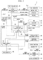
- Fig. 2 is a block diagram of a main part of the endoscope system.
- Fig. 3 is a flowchart illustrating a control procedure by a control device of the endoscope system.
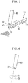
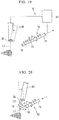
- Figs. 4 to 7 are views describing actions of the endoscope system.
- An endoscope system 1 according to the present embodiment illustrated in Fig. 1 is a medical system used for surgery and the like.
- the endoscope system 1 includes a first endoscope 10, an arm 20, a first image-processing device 25, a first sub-monitor 26, a second endoscope 30, a second image-processing device 36, a second sub-monitor 37, a position-and-orientation-detecting device 41, a main monitor 45, and a control device 50.
- the first endoscope 10 is an endoscope for acquiring an image (narrow-angle image) with a narrow area including a treatment site as an imaging target and displaying the image on the first sub-monitor and the main monitor 45.
- the first endoscope 10 is connected to the first image-processing device 25 via a signal line SL1.
- the first image-processing device 25 and the control device 50 are connected via a signal line SL1'.
- the first endoscope 10 has an insertion part 11 and a driving part 15.
- the insertion part 11 is an elongated part inserted into a patient's body, which is a treatment target, from outside the body.
- the insertion part 11 has an imaging part 12 (first imaging part), a joint part 13, and a shaft part 14.
- the imaging part 12 has, for example, an image sensor and an objective optical system (both of which are not illustrated).
- the image sensor of the imaging part 12 can, for example, acquire a bright field image of the imaging target site.
- the objective optical system of the imaging part 12 has a predetermined optical axis L1.
- a field-of-view center of the image captured by the imaging part 12 is a position of the optical axis L1 of the imaging part 12.
- a field angle of the imaging part 12 of the first endoscope 10 may be equal to a field angle of an imaging part 32 of the second endoscope 30 or may be different from the field angle of the imaging part 32 of the second endoscope 30.
- the narrow-angle image captured by the imaging part 12 of the first endoscope 10 is an image with a part of an image captured by the imaging part 32 of the second endoscope 30 as an imaging field of view, but the embodiments are not limited to meaning that the field angle of the imaging part 12 of the first endoscope 10 is narrower than the field angle of the imaging part 32 of the second endoscope 30.
- the joint part 13 has a plurality of joint elements connected to each other via a rotation shaft.
- the joint part 13 is deformable to move the imaging part 12 with respect to the shaft part 14. Further, the joint part 13 is operable to adjust a position of the imaging part 12 and a direction of the imaging field-of-view thereof.
- An operation wire 18 configured to transmit power for operating the joint part 13 is connected to the joint part 13.
- the shaft part 14 has a rigid cylindrical shape to guide the imaging part 12 to the vicinity of the treatment site in the body.
- a signal line (not illustrated) from the imaging part 12 and the operation wire 18 for connecting the joint part 13 to the driving part 15, which will be described below, to operate the joint part 13 are wired inside the shaft part 14.
- the driving part 15 is arranged at an end portion of the insertion part 11 opposite to the imaging part 12 side (referred to as a proximal end portion of the first endoscope 10 in the present embodiment).
- the driving part 15 is fixed to the shaft part 14.
- the signal line (not illustrated) extending from the imaging part 12 and the operation wire 18 extending from the joint part 13 are wired inside the driving part 15.
- the driving part 15 has an actuator 16 connected to the operation wire 18 to move the operation wire 18, and an encoder 17 for detecting an operation amount of the actuator 16.
- the actuator 16 provided in the driving part 15 operates in accordance with control by the control device 50.
- the driving part 15 also has a function as an adapter for attaching the first endoscope 10 to the arm 20.
- the insertion part 11 may have a treatment tool (not illustrated) for performing incision, suturing, or the like on the treatment site at a distal end.
- the insertion part 11 may also have a channel for inserting a known treatment tool for an endoscope.
- the first endoscope 10 may be able to rotate the imaging field of view of the imaging part 12 about the field-of-view center as the center of rotation (for example, about the optical axis L1 of the imaging part 12 as the center of rotation).
- the rotation of the imaging field-of-view may be configured to mechanically rotate the imaging part 12 or configured to rotate an image acquired by the image sensor of the imaging part 12 by image processing.
- the arm 20 holds the first endoscope 10 in a desired position and orientation or moves the first endoscope 10 in a desired direction.
- the arm 20 is connected to the control device 50 via a signal line SL2.
- the arm 20 has link parts 21, joint parts 22, actuators 23, and encoders 24.
- the link parts 21 include a distal link part 21a having a detachable structure to which the driving part 15 of the first endoscope 10 is attachable, and a plurality of proximal link parts 21b configured to connect joint elements constituting the joint parts 22.
- the joint parts 22 connect two adjacent link parts 21 such that the two adjacent link parts 21 are bendable, for example. Some of the joint parts 22 constituting the plurality of joint parts 22 may rotatably connect two adjacent link parts 21 such that center lines thereof are coaxial.
- An upper limit of degrees of freedom of the arm 20 is not particularly limited.
- the arrangement, the number, or the like of the joint parts 22 may be such that a minimum necessary degree of freedom can be given to the arm 20 to control the position and orientation of the first endoscope 10.
- the actuator 23 is arranged in the joint part 22.
- the actuator 23 operates the joint part 22 in accordance with operation control by the control device 50.
- the encoders 24 are arranged in the plurality of joint parts 22.
- the encoders 24 are arranged in all of the joint parts 22 included in the arm 20.
- the encoders 24 are electrically connected to the control device 50, which will be described below.
- the encoders 24 output movement amounts of the joint parts 22 to the control device 50.
- the encoders 24 may also output signals indicating absolute angles of the joint parts 22 to the control device 50.
- the first image-processing device 25 is connected to the imaging part 12 of the first endoscope 10.
- the first image-processing device 25 receives image information captured by the imaging part 12 of the first endoscope 10 from the imaging part 12, outputs the image information to the first sub-monitor 26 as a video signal, and outputs the image information to an image control part 52 of the control device 50.
- the first sub-monitor 26 displays a video on the basis of the video signal output from the first image-processing device 25.
- the first sub-monitor 26 may display a narrow-angle image including a treatment site.
- the second endoscope 30 is an endoscope for acquiring an image (wide-angle image) with a wide area including a treatment site as an imaging target and displaying the image on the second sub-monitor and the main monitor 45.
- the second endoscope 30 is connected to the second image-processing device 36 via a signal line SL3.
- the second image-processing device 36 and the control device 50 are connected via a signal line SL3'.
- the second endoscope 30 has an insertion part 31 and an operation part 34.
- the insertion part 31 of the second endoscope 30 has a thin, long rod shape as a whole.
- the insertion part 31 of the second endoscope 30, for example, has a property of being rigid. That is, in the present embodiment, the second endoscope 30 is a rigid mirror.
- the insertion part 31 of the second endoscope 30 has the imaging part 32 (second imaging part) and a shaft part 33.
- the imaging part 32 of the second endoscope 30 has, for example, an image sensor and an objective optical system (both of which are not illustrated).
- the image sensor of the imaging part 32 of the second endoscope 30 can, for example, acquire a bright field image of an imaging target site.
- the objective optical system of the imaging part 32 has a predetermined optical axis L2.
- a field-of-view center of the image captured by the imaging part 32 is a position of the optical axis L2 of the imaging part 32.
- the image captured by the imaging part 32 of the second endoscope 30 is transmitted to the control device 50, which will be described below.
- a field angle of the imaging part 32 of the second endoscope 30 may be equal to a field angle of the imaging part 12 of the first endoscope 10 or may be different from the field angle of the imaging part 12 of the first endoscope 10.
- the wide-angle image captured by the imaging part 32 of the second endoscope 30 is an image that captures an area wider than the imaging field of view of the imaging part 12 of the first endoscope 10, but the embodiments are not limited to meaning that the field angle of the imaging part 32 of the second endoscope 30 is wider than the field angle of the imaging part 12 of the first endoscope 10.
- the shaft part 33 of the second endoscope 30 has a rigid cylindrical shape to guide the imaging part 32 of the second endoscope 30 to the vicinity of the treatment site in the body.
- the operation part 34 is arranged at an end portion of the insertion part 31 of the second endoscope 30 opposite to the imaging part 32 side (referred to as a proximal end portion of the second endoscope 30 in the present embodiment).
- the operation part 34 has a gripping part 35.
- the gripping part 35 is a portion that can be gripped by an operator who operates the second endoscope 30.
- an operator can move the entire insertion part 31 of the second endoscope 30 by gripping and moving the gripping part 35. That is, in the present embodiment, it is possible for the operator to move an imaging field of view of the imaging part 32 of the second endoscope 30 by gripping and moving the gripping part 35 when using the second endoscope 30.
- a viewpoint change switch 39 and a field-of-view adjustment switch 40 which will be described below, may be arranged in the gripping part 35.
- the constitution of the second endoscope 30 is not limited to the above constitution.
- the second endoscope 30 may be a rigid mirror or a flexible endoscope having the imaging part 32 for capturing the wide-angle image.
- a field-of-view direction of the imaging part 32 of the second endoscope 30 is not limited to the above constitution as long as the direction is fixed by the insertion part 31 of the second endoscope 30 or can be grasped by the control device 50.
- the second image-processing device 36 is connected to the imaging part 32 of the second endoscope 30.
- the second image-processing device 36 receives image information captured by the imaging part 32 of the second endoscope 30 from the imaging part 32, outputs the image information to the second sub-monitor 37 as a video signal, and outputs the image information to the image control part 52 of the control device 50.
- the second sub-motor 37 displays a video on the basis of the video signal output from the second image-processing device 36.
- the second sub-monitor 37 may display a wide-angle image including a treatment site.
- an arm input part 38 is connected to a drive control part 53 of the control device 50.
- the arm input part 38 is, for example, operated by a scopist and outputs a predetermined operation signal for operating the arm 20 to the drive control part 53.
- the viewpoint change switch 39 is electrically connected to the image control part 52 of the control device 50.
- the viewpoint change switch 39 is a changeover switch for selecting one desired image from the narrow-angle image obtained by the first endoscope 10 and the wide-angle image obtained by the second endoscope 30.
- the viewpoint change switch 39 may be a push-button switch and, every time the viewpoint change switch 39 is pressed, an image displayed on the main monitor 45 may be switched to a wide-angle-image or a narrow-angle image.
- the viewpoint change switch 39 may be arranged at a position at which a person who performs a treatment on a treatment site (for example, a surgeon), a person who operates the first endoscope 10 or the second endoscope 30 (for example, a scopist), or the like can easily operate the viewpoint change switch 39.
- the viewpoint change switch 39 may be attached to a medical instrument operated by a surgeon performing a treatment on a treatment site.
- the viewpoint change switch 39 may also be arranged in the vicinity of the gripping part 35 of the second endoscope 30 (see Fig. 1 ). Because the viewpoint change switch 39 of the present embodiment is arranged at a position at which the viewpoint change switch 39 can be easily operated by an operator operating the second endoscope 30, the viewpoint can be easily changed during a treatment using the second endoscope 30.
- the field-of-view adjustment switch 40 is electrically connected to the drive control part 53 of the control device 50.
- the field-of-view adjustment switch 40 is a switch for inputting, to the drive control part 53 of the control device 50, an input for operating the first endoscope 10 so that a field-of-view center of the narrow-angle image obtained by the first endoscope 10 and a field-of-view center of the wide-angle image obtained by the second endoscope 30 coincide with each other.
- the field-of-view adjustment switch 40 may be arranged at a position at which a person performing a treatment on a treatment site (for example, a surgeon), a person operating the first endoscope 10 or the second endoscope 30 (for example, a scopist), or the like can easily operate the field-of-view adjustment switch 40.
- the field-of-view adjustment switch 40 may be arranged in the vicinity of the gripping part 35 of the second endoscope 30.
- the field-of-view adjustment switch 40 is a push-button switch and, every time the field-of-view adjustment switch 40 is pressed, an operation in which the control device 50 moves the first endoscope 10 so that a field-of-view center of a narrow-angle image is made to coincide with a field-of-view center of a wide-angle image is started.
- the field-of-view adjustment switch 40 of the present embodiment is arranged at a position at which the field-of-view adjustment switch 40 can be easily operated by an operator operating the second endoscope 30, a field-of-view center of a narrow-angle image and a field-of-view center of a wide-angle image may be easily made to coincide during a treatment using the second endoscope 30.
- the position-and-orientation-detecting device 41 detects positions and orientations of the first endoscope 10 and the second endoscope 30 in a space such as an operating room in which the endoscope system 1 according to the present embodiment is installed.
- the position-and-orientation-detecting device 41 has a first marker 42, a second marker 43, and a camera 44. Also, the position-and-orientation-detecting device 41 is connected to the control device 50, which will be described below.
- the first marker 42 is arranged in the driving part 15 of the first endoscope 10.
- the first marker 42 is a marker different from the second marker 43 to distinguish between the first endoscope 10 and the second endoscope 30.
- a constitution of the first marker 42 is not particularly limited as long as the first marker 42 can be captured by the camera 44 and can be recognized by the control device 50.
- the first marker 42 may have a shape unique to the first marker 42, have a pattern of a predetermined shape, or emit predetermined light to the camera 44.
- the second marker 43 is arranged in the operation part 34 of the second endoscope 30.
- the second marker 43 is a marker different from the first marker 42 to distinguish between the first endoscope 10 and the second endoscope 30.
- a constitution of the second marker 43 is not particularly limited as long as the second marker 43 can be captured by the camera 44 and can be recognized by the control device 50.
- the second marker 43 may have a shape unique to the second marker 43, have a pattern of a predetermined shape, or emit predetermined light to the camera 44.
- the camera 44 captures an image including the first marker 42 and the second marker 43 and transmits an image to the control device 50.
- the camera 44 acquires a plurality of images having different fields of view.
- the camera 44 may include two imaging devices having different fields of view.
- the camera 44 is fixed in a part of a space such as an operating room in which the endoscope system 1 is arranged. For example, by the camera 44 being fixed to a part of an operating room and capturing an image including the first marker 42 and the second marker 43, positions and orientations of the first marker 42 and the second marker 43 in a predetermined coordinate system (reference coordinate system) based on a position of the camera 44 can be detected.
- a predetermined coordinate system reference coordinate system
- the main monitor 45 is connected to the control device 50 via a signal line SL4.
- the main monitor 45 may display an image captured by the imaging part 12 of the first endoscope 10 and an image captured by the imaging part 32 of the second endoscope 30 via the image control part 52.
- the main monitor 45 displays one image selected from the image captured by the first endoscope 10 and the image captured by the second endoscope 30 via a switching input with respect to the viewpoint change switch 39.
- the display state on the main monitor 45 is controlled by the image control part 52 of the control device 50.
- a specific constitution of the main monitor 45 is not particularly limited. For example, a known display system that displays an image on the basis of an analog or digital video signal may be appropriately selected as the main monitor 45.
- the control device 50 controls the arm 20 and the second endoscope 30. Further, the control device 50 causes the main monitor 45 to display an image from the first endoscope 10, an image from the second endoscope 30, or the like.
- the control device 50 illustrated in Figs. 1 and 2 includes a position calculation part 51, the image control part 52, and the drive control part 53.
- the position calculation part 51 receives an image signal from the camera 44 and calculates positions of the first marker 42 and the second marker 43.
- the position calculation part 51 stores the positions and orientations of the first marker 42 and the second marker 43 in a predetermined coordinate system (reference coordinate system) based on a position of the camera 44 as coordinate information.
- the image control part 52 is connected to the first image-processing device 25, the second image-processing device 36, the drive control part 53, the viewpoint change switch 39, and the main monitor 45.
- the image control part 52 generates predetermined information for operating the drive control part 53 by using image information output from the first image-processing device 25 and image information output from the second image-processing device 36 and outputs the predetermined information to the drive control part 53.
- the image control part 52 acquires an image captured by the first endoscope 10 and an image captured by the second endoscope 30 and outputs an image corresponding to a switching input with respect to the viewpoint change switch 39 to the main monitor 45.
- the main monitor 45 may consist of two screens, a main screen and a sub-screen, and the image control part 52 may cause an image designated by the switching input with respect to the viewpoint change switch 39 to be displayed on the main screen and cause an image not selected by the switching input to be displayed on the sub-screen.
- the drive control part 53 is connected to the position calculation part 51.
- the drive control part 53 is also connected to the actuator 16 and the encoder 17 of the first endoscope 10 and the actuators 23 and the encoders 24 of the arm 20. Further, the drive control part 53 is connected to the arm input part 38.
- the drive control part 53 controls operations of the joint part 13 and the arm 20 of the first endoscope 10 on the basis of an operation signal generated by an operation on the arm input part 38 by the operator.
- the position calculation part 51 recognizes the first marker 42 from an image captured by the camera 44 of the position-and-orientation-detecting device 41.
- the image to be transmitted from the camera 44 to the position calculation part 51 is a set of a plurality of images having different fields of view, and the position calculation part 51 recognizes the position and orientation of the first marker 42 in the reference coordinate system from the plurality of images.
- the first marker 42 is arranged in the driving part 15 of the first endoscope 10, and the position of the first endoscope 10 with respect to the position of the first marker 42 is pre-stored in the control device 50. Because of this, the position calculation part 51 may recognize the position and orientation of the first endoscope 10 on the basis of the position and orientation of the first maker 42.
- the position calculation part 51 uses a predetermined reference point in the driving part 15 of the first endoscope 10 as the position of the first endoscope 10. That is, the position calculation part 51 recognizes coordinates of the reference point of the first endoscope 10 in the reference coordinate system as the position of the first endoscope 10. Further, the position calculation part 51 uses a direction of the first marker 42 in the reference coordinate system as the orientation of the first endoscope 10.
- the drive control part 53 recognizes the position and orientation of the imaging part 12 arranged at a distal end portion of the joint part 13 in addition to the position and orientation of the first endoscope 10. For example, the drive control part 53 recognizes coordinates of a part of the imaging part 12 in the reference coordinate system as the position of the imaging part 12. Further, the drive control part 53 recognizes a direction of an optical axis in the reference coordinate system as the orientation of the imaging part 12.
- a first position and orientation detector configured to detect the position and orientation of the first endoscope 10 in the reference coordinate system is constituted by the position-and-orientation-detecting device 41, the position calculation part 51, and the drive control part 53. Further, in the present embodiment, the control device 50 is capable of detect positions and orientations of the first endoscope 10 and an optical axis thereof.
- the position calculation part 51 recognizes the second marker 43 from an image captured by the camera 44 of the position-and-orientation-detecting device 41.
- the position calculation part 51 recognizes the position and orientation of the second marker 43 similarly to the recognition of the position and orientation of the first marker 42.
- the drive control part 53 recognizes coordinates of a part of the imaging part 32 of the second endoscope 30 in the reference coordinate system as the position of the imaging part 32 of the second endoscope 30. Further, the drive control part 53 recognizes a direction of an optical axis in the reference coordinate system as the orientation of the imaging part 32 of the second endoscope 30.
- a second position and orientation detector configured to detect the position and orientation of the second endoscope 30 in the reference coordinate system is constituted by the position-and-orientation-detecting device 41, the position calculation part 51, and the drive control part 53. Further, in the present embodiment, the control device 50 can detect the position and orientation of the optical axis L2 of the second endoscope 30.
- the drive control part 53 receives an input to the arm input part 38 arranged in the gripping part 35 of the second endoscope 30 and operates the first endoscope 10 and the arm 20 on the basis of the input.
- the drive control part 53 receives an input to the field-of-view adjustment switch 40 arranged in the gripping part 35 of the second endoscope 30 and operates the first endoscope 10 and the arm 20 on the basis of the input.
- the drive control part 53 that received the input to the field-of-view adjustment switch 40 operates the first endoscope 10 and the arm 20 as shown in each step from Step S1 to Step S4.
- the drive control part 53 recognizes the position and orientation of the first endoscope 10 in the reference coordinate system and the position and orientation of the optical axis L1 of the first endoscope 10 in the reference coordinate system (a first calculating step, Step S1).
- Step S2 the drive control part 53 recognizes the position and orientation of the optical axis L2 of the second endoscope 30 in the reference coordinate system (a second calculating step, Step S2).
- Step S2 may be performed before Step S1 or performed after Step S1.
- Step S3 the drive control part 53 calculates an operation amount for operating the first endoscope 10 and the arm 20 such that the first endoscope 10 and the arm 20 approach the position and orientation of the optical axis L2 of the second endoscope 30 recognized in Step S2 (an operation amount-calculating step, Step S3).
- Step S3 the drive control part 53 sets a position deviated by a predetermined distance toward a front side in an optical axis direction from coordinates indicating the position of the optical axis L2 of the second endoscope 30 as a movement target position of the optical axis L1 of the first endoscope 10. That is, in Step S3, the drive control part 53 sets the movement target position of the optical axis L1 of the first endoscope 10 in an area between a distal end of the imaging part 32 of the second endoscope 30 and an imaging target site. In Step S3, the movement target position set by the drive control part 53 has coordinates of one point on the optical axis L2 of the second endoscope 30 in the reference coordinate system.
- the precision of the movement target position set by the drive control part 53 in Step S3 may not be that strict. This is because if the optical axis L1 of the first endoscope 10 and the optical axis L2 of the second endoscope 30 are parallel to each other, deviation between field-of-view centers on an image falls within an extent such that there is no practical problem even when the optical axes are spaced apart by some distance.
- the movement target position set by the drive control part 53 in Step S3 may be set as an area of a certain range to allow a certain degree of error. For example, as illustrated in Fig.
- a movement target position X1 set by the drive control part 53 in Step S3 may have coordinates along a plane orthogonal to the optical axis L2 of the second endoscope 30 in the reference coordinate system and within a circle C1 having a predetermined diameter about the optical axis.
- the movement target position set by the drive control part 53 in Step S3 may also have coordinates within a sphere whose center has coordinates of the position of the optical axis L2 of the second endoscope 30 in the reference coordinate system.
- the movement target position set by the drive control part 53 in Step S3 may also have coordinates within a cylinder whose center line is the optical axis L2 of the second endoscope 30 in the reference coordinate system.
- Step S3 the drive control part 53 sets a movement path from a current position of the optical axis L1 of the first endoscope 10 to a movement target position.
- a method of setting the movement path from the current position of the optical axis L1 of the first endoscope 10 to the movement target position is not particularly limited as long as the method takes into consideration that there is no obstacle in the movement path.
- the drive control part 53 calculates an operation amount of the arm 20 for moving the first endoscope 10 so that the optical axis moves along the movement path.
- the drive control part 53 sets an operation target direction of the imaging part 12 so that a direction of the optical axis L1 of the first endoscope 10 is made to coincide with a direction of the optical axis L2 of the second endoscope 30.
- the drive control part 53 calculates a joint driving amount of the joint part 13 for rotating the imaging part 12 around coordinates indicating the position of the optical axis L1 of the first endoscope 10 so that a direction of the optical axis L1 of the first endoscope 10 when the optical axis L1 of the first endoscope 10 is located at the movement target position is parallel to a direction of the optical axis L2 of the second endoscope 30.
- the operation target direction of the imaging part 12 set by the drive control part 53 in Step S3 may be set as an area of a certain range to allow a certain degree of error.
- Step S3 the drive control part 53 calculates the operation amount of the arm 20 and the operation amount of the joint part 13.
- Step S3 This completes Step S3, and the procedure proceeds to Step S4.
- Step S4 is an instructing step of outputting operation instructions for operating the arm 20 and the joint part 13 on the basis of the operation amount of the arm 20 and the operation amount of the joint part 13 calculated in Step 3 above to the arm 20 and the joint part 13.
- Step S4 the drive control part 53 operates the arm 20 and the joint part 13 by outputting operation instructions to the arm 20 and the joint part 13.
- the drive control part 53 first outputs an operation instruction to the arm 20, thereby moving the first endoscope 10 until the position of the optical axis L1 of the first endoscope 10 reaches the movement target position on the optical axis L2 of the second endoscope 30.
- the drive control part 53 outputs an operation instruction to the joint part 13, thereby rotating the imaging part 12 of the first endoscope 10 on the optical axis L2 of the second endoscope 30 until the optical axis L1 of the first endoscope 10 is coaxial with the optical axis L2 of the second endoscope 30.
- the drive control part 53 calculates operation amounts of each degree of freedom of the joint part 13 and the arm 20 by using inverse kinematics and determines a control amount of each of the actuators.
- the drive control part 53 outputs a driving signal on the basis of the control amount.
- the drive control part 53 determines, by the encoders 24 and 17 that detect orientations of the arm 20 and the joint part 13, whether the optical axis L1 of the first endoscope 10 has reached the movement target position, and when the drive control part 53 determines that the optical axis L1 of the first endoscope 10 reached the movement target position, Step S4 is completed.
- the drive control part 53 operates the first endoscope 10 and the arm 20 so that the optical axis L1 of the first endoscope 10 and the optical axis L2 of the second endoscope 30 become coaxial with each other corresponding to the input to the field-of-view adjustment switch 40.
- the first endoscope 10 and the second endoscope 30 are inserted into the body. That is, the insertion part 11 of the first endoscope 10 and the insertion part 31 of the second endoscope 30 are, for example, inserted into the body via a trocar and, as illustrated in Fig. 4 , the imaging part 32 of the second endoscope 30 is guided to the vicinity of a treatment site in the body, and the imaging part 12 of the first endoscope 10 is guided to a position closer to the treatment site than the second endoscope 30 is, in the vicinity of the treatment site.
- the imaging part 12 of the first endoscope 10 has a narrower imaging field-of-view than the imaging part 32 of the second endoscope 30. That is, in a case in which the first endoscope 10 and the second endoscope 30 are arranged in the body with the above distance relationship, the first endoscope 10 can capture a narrow-angle image including the treatment site, and the second endoscope 30 can capture a wide-angle image including the treatment site.
- the first endoscope 10 and the second endoscope 30 may have optical functions such as zooming and macro, description taking such optical functions into consideration will be omitted in the present specification.
- the operator uses the second endoscope 30 and observes a wide area including the treatment site from a panoramic view.
- the operator mainly operates the second endoscope 30.
- the operator grasps a situation in the vicinity of the treatment site by moving the operation part 34 of the second endoscope 30 and observing a desired site.
- the drive control part 53 controls the arm 20 and the first endoscope 10 according to the control procedure from Step S1 to Step S4 above.
- the imaging part 12 of the first endoscope 10 enters the field of view of the second endoscope 30. Further, when the optical axis L1 of the imaging part 12 of the first endoscope 10 reaches an area within the circle C1 around the point X1 on the optical axis L2 of the second endoscope 30 as illustrated in Fig. 6 , the movement of the imaging part 12 is stopped and then, the direction of the imaging part 12 of the first endoscope 10 is changed so that the optical axis L1 of the first endoscope 10 is coaxial with the optical axis L2 of the second endoscope 30 as illustrated in Fig. 7 .
- the imaging part 12 of the first endoscope 10 is located at a field-of-view center of an image captured by the imaging part 32 of the second endoscope 30.
- the operator can grasp that the imaging part 12 of the first endoscope 10 is arranged in the vicinity of the treatment site from the wide-angle image captured by the imaging part 32 of the second endoscope 30.
- the operator makes an input to the viewpoint change switch 39.
- the image control part 52 of the control device 50 switches the image displayed on the main monitor 45 from the image captured by the imaging part 32 of the second endoscope 30 to the image captured by the imaging part 12 of the first endoscope 10.
- a field-of-view center in the image captured by the imaging part 12 of the first endoscope 10 is coincident with a field-of-view center in the image captured by the imaging part 32 of the second endoscope 30. Because of this, by switching from the image captured by the imaging part 32 of the second endoscope 30 to the image captured by the first endoscope 10, an image in which a part including the field-of-view center of the wide-angle image is magnified (zoomed in) is displayed on the main monitor 45.
- the image captured by the imaging part 12 of the first endoscope 10 is a narrow-angle image capturing the treatment site within the field of view.
- the operator can perform a treatment on the treatment site while looking at the image captured by the imaging part 12 of the first endoscope 10.
- the operator can switch the image to be displayed on the main monitor 45 from the narrow-angle image captured by the imaging part 12 of the first endoscope 10 to the wide-angle image captured by the imaging part 32 of the second endoscope 30 by using the viewpoint change switch 39.
- This may be performed, for example, in a case in which a state of the surroundings of a treatment site is checked during treatment using a narrow-angle image.
- the imaging part 32 of the second endoscope 30 has a wide area including the imaging field of view of the first endoscope 10 as an imaging field of view.
- the operator can observe surroundings of the treatment site by gripping and moving the operation part 34 of the second endoscope 30 in the state in which the image captured by the imaging part 32 of the second endoscope 30 is displayed on the main monitor 45.
- the first endoscope 10 is stopped in a state in which the first endoscope 10 can acquire a narrow-angle image capturing the treatment site at the field-of-view center.
- the narrow-angle image including the treatment site is displayed again on the main monitor 45.
- the operator may easily restore the position of the field-of-view center of the imaging part 32 of the second endoscope 30 to the treatment site by referring to the position of the imaging part 12 of the first endoscope 10 based on the image captured by the imaging part 32 of the second endoscope 30.
- the operator After the operator substantially returns the position of the field-of-view center of the imaging part 32 of the second endoscope 30 to the treatment site, the operator makes an input to the viewpoint change switch 39 and switches the image displayed on the main monitor 45 from the image captured by the imaging part 32 of the second endoscope 30 to the image captured by the imaging part 12 of the first endoscope 10.
- the first endoscope 10 is stopped in a state in which the first endoscope 10 can acquire a narrow-angle image capturing the treatment site at the field-of-view center. That is, the first endoscope 10 maintains the positional relationship before switching from the narrow-angle image to the wide-angle image. Because of this, the operator may easily resume the treatment after the image displayed on the main monitor 45 is switched from the wide-angle image to the narrow-angle image.
- the positional relationship between the treatment site and the first endoscope 10 is changed, and the position or orientation of the treatment site in the image captured by the imaging part 12 of the first endoscope 10 changes in some cases.
- the operator may move the imaging part 12 of the first endoscope 10 to the treatment site by making an input to the field-of-view adjustment switch 40.
- the drive control part 53 controls the arm 20 and the first endoscope 10 according to the control procedure from Step S1 to Step S4 above, the optical axis L2 of the imaging part 32 of the second endoscope 30 and the optical axis L1 of the imaging part 12 of the first endoscope 10 become coaxial with each other.
- a narrow-angle image capturing the treatment site at the field-of-view center is displayed on the main monitor 45, and a treatment on the new site can be performed.
- the operator may have to perform another treatment with a new site as a treatment site in some cases.
- a new site is set as a treatment site, in the state in which the new site, which is the treatment site, is captured at the field-of-view center of the imaging part 32 of the second endoscope 30, the operator may move the imaging part 12 of the first endoscope 10 to the new site by making an input to the field-of-view adjustment switch 40.
- the drive control part 53 controls the arm 20 and the first endoscope 10 according to the control procedure from Step S1 to Step S4 above, the optical axis L2 of the imaging part 32 of the second endoscope 30 and the optical axis L1 of the imaging part 12 of the first endoscope 10 become coaxial with each other.
- a narrow-angle image capturing the new site as the treatment site at the field-of-view center is displayed on the main monitor 45, and a treatment on the new site can be performed.
- a surgeon performing a treatment using the endoscope system 1 according to the present embodiment may perform a treatment while looking at a wide-angle image and a narrow-angle image including a treatment site by using the main monitor 45.
- a scopist operating the first endoscope 10 and the second endoscope 30 of the endoscope system 1 according to the present embodiment may adjust the position or orientation of each of the endoscopes independently of the treatment by the surgeon or in cooperation with the treatment by the surgeon by using the first sub-monitor 26 and the second sub-monitor 37.
- the optical axes of the two endoscopes are coaxial with each other and respectively capture a narrow-angle image and a wide-angle image
- an operational feeling such as zoom out for a narrow-angle image and zoom in for a wide-angle image may be obtained.
- the endoscope system 1 according to the present embodiment because most of the operations for making the optical axes of the two endoscopes coincident with each other can be automated, the burden on the operator is reduced.
- the initial close field of view is a surgical field (field of view) created by a surgeon giving an instruction to a scopist to have a state in which it is easy to perform a treatment.
- the field of view that is initially created is destroyed.
- the surgeon can check the surroundings of the treatment site in a wide-angle field of view at a moment when the surgeon wants to do so, and after the checking, the surgeon can promptly return to a field of view in which the treatment was being performed. Because of this, in the present embodiment, there is little time lag before returning to performing the treatment, and the surgeon may feel less stress and fatigue. Further, in the present embodiment, because surrounding tissues can be appropriately checked using a wide-angle image, there is a possibility that safer surgery may be able to be performed.
- FIG. 8 is a schematic view illustrating a part of an endoscope system according to the second embodiment of the present invention.
- Fig. 9 is a flowchart illustrating a control procedure by a control device of the endoscope system.
- An endoscope system 2 which is partly illustrated in Fig. 8 , includes a distance measurer for measuring a distance to an imaging target site provided in the first endoscope 10, the second endoscope 30, and a control device 66.
- the first endoscope 10 includes, instead of the imaging part 12 of the first embodiment, an imaging part 60 having a constitution different from that of the imaging part 12 disclosed in the first embodiment.
- the second endoscope 30 according to the present embodiment includes, instead of the imaging part 32 of the first embodiment, an imaging part 63 having a constitution different from that of the imaging part 32 disclosed in the first embodiment.
- the endoscope system 2 includes, instead of the control device 50 of the first embodiment, a control device 66 that includes, in an operation procedure, a step of operating the first endoscope 10 and the arm 20 (see Fig. 1 ) in consideration of a distance to an imaging target on the basis of images respectively captured by the imaging parts 60 and 63 of the present embodiment.
- the imaging part 60 of the first endoscope 10 has a different constitution from the imaging part 12 of the first endoscope 10 disclosed in the first embodiment in that the imaging part 60 can acquire three-dimensional information on an imaging target site.
- the first endoscope 10 includes a left-side imaging part 61 and a right-side imaging part 62.
- the left-side imaging part 61 and the right-side imaging part 62 capture a set of two images having parallax with respect to the same imaging target site.
- each of the left-side imaging part 61 and the right-side imaging part 62 may have an image sensor and an objective optical system independently.
- An image captured by the left-side imaging part 61 and an image captured by the right-side imaging part 62 are transmitted to an image control part 67 of the control device 66 via a signal line (not illustrated) as in the first embodiment.
- the imaging part 63 of the second endoscope 30 includes, for example, a left-side imaging part 64 and a right-side imaging part 65 like the imaging part 60 of the first endoscope 10.
- the image control part 67 of the control device 66 has a function of measuring a distance from the first endoscope 10 to an imaging target site on the basis of images respectively acquired by the left-side imaging part 61 and the right-side imaging part 62 of the first endoscope 10.
- the image control part 67 of the control device 66 measures a distance to the imaging target site using the parallax of images acquired by the left-side imaging part 61 and the right-side imaging part 62 of the first endoscope 10.
- the image control part 67 of the control device 66 has a function of measuring a distance from the second endoscope 30 to an imaging target site on the basis of images respectively acquired by the left-side imaging part 64 and the right-side imaging part 65 of the second endoscope 30.
- the image control part 67 of the control device 66 measures a distance to the imaging target site using the parallax of images acquired by the left-side imaging part 64 and the right-side imaging part 65 of the second endoscope 30.
- the constitution for measuring a distance between the first endoscope 10 and an imaging target site thereof or a distance between the second endoscope 30 and an imaging target site thereof is not limited to the above constitution.
- the first endoscope 10 or the second endoscope 30 may have an appropriate constitution such as a known laser distance-measuring device or infrared distance-measuring device.
- control device 66 of the present embodiment for moving the first endoscope 10 and the arm 20 will be mainly described with respect to differences from the control procedure in the first embodiment.
- the control device 66 includes the steps from Step S1 to Step S4 disclosed in the first embodiment in a control procedure. Because of this, in a state in which both the first endoscope 10 and the second endoscope 30 capture a treatment site at a field-of-view center, the endoscope system 2 according to the present embodiment may capture a narrow-angle image and a wide-angle image in a positional relationship in which optical axes thereof coincide with each other and may display any one or both of the narrow-angle image and the wide-angle image on the main monitor 45.
- a control procedure in the state in which both the first endoscope 10 and the second endoscope 30 capture an image capturing a treatment site at a field-of-view center, a control procedure (see Fig. 9 ) in a case in which the control device 66 operates the first endoscope 10 and the arm 20 by following movement of the second endoscope 30 is different from the first embodiment.
- the control device 66 measures a distance between an imaging target site of the first endoscope 10 and the first endoscope 10. For example, the control device 66 calculates a distance from coordinates of a position of an optical axis of the imaging part 60 of the first endoscope 10 in the reference coordinate system to a field-of-view center of one predetermined image of the set of two images captured by the imaging part 60 of the first endoscope 10 (a first distance-measuring step, Step S11, see Fig. 9 ).
- the control device 66 measures a distance between an imaging target site of the second endoscope 30 and the second endoscope 30. For example, the control device 66 calculates a distance from coordinates of a position of an optical axis of the imaging part 63 of the second endoscope 30 in the reference coordinate system to a field-of-view center of one predetermined image of the set of two images captured by the imaging part 63 of the second endoscope 30 (a second distance-measuring step, Step S12, see Fig. 9 ). Step S12 may be performed before Step S11 or performed after Step S11.
- Step S11 and S12 both the first endoscope 10 and the second endoscope 30 capture a treatment site at a field-of-view center, and distances calculated by Step S11 and Step S12 are a distance between the first endoscope 10 and the treatment site and a distance between the second endoscope 30 and the treatment site, respectively.
- the operator moves the second endoscope 30 and starts a treatment with a new site as a treatment site, the operator operates the second endoscope 30 so that the field-of-view center of the image captured by the imaging part 63 of the second endoscope 30 is adjusted to the new site, which is the treatment site. Then, the operator makes an input to the field-of-view adjustment switch 40.
- Step S13 the control device 66 detects the position and orientation of the optical axis L2 of the second endoscope 30 as in the first embodiment.
- Step S13 the new treatment site is located at the field-of-view center of the image captured by the imaging part 63 of the second endoscope 30. Because of this, in Step S13, a distance between the second endoscope 30 and the new treatment site is calculated.
- a drive control part 68 of the control device 66 calculates an operation amount for operating the first endoscope 10 and the arm 20 such that the first endoscope 10 and the arm 20 approach the position and orientation of the optical axis L2 of the second endoscope 30 recognized in Step S13 (Step S14, see Fig. 9 ).
- Step S14 the drive control part 68 sets a position deviated by a predetermined distance toward a front side in an optical axis direction from coordinates indicating the position of the optical axis L2 of the second endoscope 30 as a movement target position of the optical axis L1 of the first endoscope 10.
- control device 66 causes, for example, the main monitor 45 to display a message prompting movement of the first endoscope 10 or the second endoscope 30 so that the second endoscope 30 is separated from the imaging target site thereof.
- control device 66 returns to Step S12, recalculates the distance between the second endoscope 30 and the imaging target site thereof, and sets the position deviated by the predetermined distance toward the front side in the optical axis direction from the coordinates indicating the position of the optical axis L2 of the second endoscope 30 as the movement target position of the optical axis L1 of the first endoscope 10.
- Step S14 the control device 66 sets the movement target position of the optical axis L1 of the first endoscope 10 in an area between a distal end and the imaging target site of the imaging part 63 of the second endoscope 30.
- the drive control part 68 of the control device 66 sets a movement path from a current position of the optical axis L1 of the first endoscope 10 to the movement target position.
- a method of setting the movement path from the current position of the optical axis L1 of the first endoscope 10 to the movement target position takes into consideration that there is no obstacle in the movement path.
- the movement path set in Step S14 may be set using the same setting method as the movement path set in Step S3 in the first embodiment.
- the drive control part 68 calculates an operation amount of the arm 20 for moving the first endoscope 10 so that the optical axis moves along the movement path.
- Step S14 the drive control part 68 sets an operation target direction of the imaging part 60 of the first endoscope 10 so that a direction of the optical axis L1 of the first endoscope 10 is made to coincide with a direction of the optical axis L2 of the second endoscope 30.
- Step S14 the drive control part 68 calculates an operation amount of the joint part 13 for rotating the imaging part 60 of the first endoscope 10 around coordinates indicating the position of the optical axis L1 of the first endoscope 10 so that a direction of the optical axis L1 of the first endoscope 10 when the optical axis L1 of the first endoscope 10 is located at the movement target position is parallel to a direction of the optical axis L2 of the second endoscope 30.
- Step S14 the drive control part 68 calculates the operation amount of the arm 20 and the operation amount of the joint part 13.
- Step S14 This completes Step S14, and the procedure proceeds to Step S15.
- Step S15 is an instructing step of outputting operation instructions for operating the arm 20 and the joint part 13 on the basis of the operation amount of the arm 20 and the operation amount of the joint part 13 calculated in Step S14 above to the arm 20 and the joint part 13 (see Fig. 9 ).
- Step S15 the drive control part 68 operates the arm 20 and the joint part 13 by outputting operation instructions to the arm 20 and the joint part 13.
- the drive control part 68 first outputs an operation instruction to the arm 20, thereby moving the first endoscope 10 until the position of the optical axis L1 of the first endoscope 10 reaches the movement target position on the optical axis L2 of the second endoscope 30.
- the drive control part 68 outputs an operation instruction to the joint part 13, thereby rotating the imaging part 60 of the first endoscope 10 on the optical axis L2 of the second endoscope 30 until the optical axis L1 of the first endoscope 10 is coaxial with the optical axis L2 of the second endoscope 30.
- Step S15 the drive control part 68 operates the first endoscope 10 and the arm 20 until the optical axis L1 of the first endoscope 10 and the optical axis L2 of the second endoscope 30 become coaxial with each other corresponding to the input to the field-of-view adjustment switch 40.
- the distance between the first endoscope 10 and the treatment site before the operations of the first endoscope 10 and the arm 20 and the distance between the first endoscope 10 and the new treatment site after the operations of the first endoscope 10 and the arm 20 are equal to each other. Because of this, in a case in which a new treatment is performed using an image captured by the imaging part 60 of the first endoscope 10, it is easy to grasp a situation of a treatment site thereof.
- the imaging part 60 of the first endoscope 10 in the movement path for moving the imaging part 60 of the first endoscope 10 from a certain treatment site (first site) to another new treatment site (second site), the imaging part 60 of the first endoscope 10 can be moved while a distance to a tissue or the like including the treatment site is kept constant.
- the drive control part 68 sets the movement path of the optical axis L1 of the first endoscope 10 so that a distance between a line connecting the first site to the second site by, for example, the shortest path, and the position of the optical axis L1 of the first endoscope 10 is always the same on the basis of an image captured by the imaging part 60 of the first endoscope 10.
- the imaging part 60 of the first endoscope 10 may move while avoiding the obstacle having irregularities corresponding to the obstacle having irregularities.
- the drive control part 68 may recognize an obstacle having irregularities on a line connecting a first site and a second site of a tissue on the basis of an image from the imaging part 60 of the first endoscope 10 and may move the first endoscope 10 while avoiding the obstacle having irregularities.
- the drive control part 68 calculates a distance between the first endoscope 10 and the tissue while appropriately adjusting the direction of the imaging part 60 in a process in which the first endoscope 10 moves, thereby moving the first endoscope 10 while the distance between the first endoscope 10 and the tissue is kept constant.
- FIG. 10 is a schematic overall view illustrating an endoscope system according to the present embodiment.
- Fig. 11 is a flowchart illustrating a control procedure by a control device 80 of the endoscope system.
- An endoscope system 3 according to the present embodiment illustrated in Fig. 10 has a different constitution from the endoscope system 1 according to the first embodiment in that the endoscope system 3 includes an arm (a second arm 71) for moving the second endoscope 30.
- the endoscope system 3 includes the first endoscope 10 and the second endoscope 30 disclosed in the first embodiment, a first arm 70 for moving the first endoscope 10, the second arm 71 for moving the second endoscope 30, and the control device 80.
- Constitutions of the first endoscope 10 and the second endoscope 30 are the same as in the first embodiment. Further, the first endoscope 10 and the second endoscope 30 in the present embodiment may be of the same type having the same constitution.
- the first arm 70 has the same constitution as the arm 20 disclosed in the first embodiment.
- the second arm 71 has the same constitution as the arm 20 disclosed in the first embodiment. That is, the second arm 71 has link parts 72, joint parts 73, actuators 74, and encoders 75.
- the operation part 34 of the second endoscope 30 may be attached to the link part 72 of the second arm 71.
- the second arm 71 may be connected to the control device 80.
- the control device 80 included in the endoscope system 3 controls operations of the first endoscope 10, the second endoscope 30, the first arm 70, and the second arm 71.
- the control device 80 includes a position calculation part 81, an image control part 82, and a drive control part 83 capable of outputting operation instructions for operating the first endoscope 10 and the first arm 70 in the same manner as in the first embodiment to the first endoscope 10 and the first arm 70.
- the drive control part 83 of the present embodiment outputs an operation instruction for operating the second arm 71 to the second arm 71.
- the drive control part 83 may be configured to control the joint part provided in the second endoscope 30.
- control device 80 Next, a constitution of the control device 80 will be described by showing a control procedure of a main part in the endoscope system 3 according to the present embodiment with reference to Fig. 11 .
- control device 80 of the endoscope system 3 has a control procedure for operating the second arm 71.
- the control device 80 moves the second endoscope 30 by operating the second arm 71 so that the optical axis L1 of the imaging part 12 of the first endoscope 10 and the optical axis L2 of the imaging part 32 of the second endoscope 30 are coaxial.
- the control procedure for moving the second endoscope 30 includes the following steps from Step S21 to Step S24.
- control device 80 recognizes the position and orientation of the optical axis L1 of the first endoscope 10 on the basis of an image including the first marker 42 captured by the camera 44 of the position-and-orientation-detecting device 41 (a first calculating step, Step S21, see Fig. 11 ).
- control device 80 recognizes the position and orientation of the second endoscope 30 on the basis of an image including the second marker 43 captured by the camera 44 of the position-and-orientation-detecting device 41 (a second calculating step, Step S22, see Fig. 11 ).
- Step S22 may be performed before Step S21 or performed after Step S21.
- the drive control part 83 of the control device 80 calculates an operation amount of the second endoscope 30 so that the optical axis L1 of the imaging part 12 of the first endoscope 10 and the optical axis L2 of the imaging part 32 of the second endoscope 30 are coaxial (an operation amount-calculating step, Step S23, see Fig. 11 ).
- the drive control part 83 of the control device 80 calculates a movement amount of the second endoscope 30 so that the position and direction of the optical axis L2 of the second endoscope 30 pass through the position of the optical axis L1 of the first endoscope 10 in the reference coordinate system and are parallel to a direction of the optical axis.
- the movement amount of the second endoscope 30 in Step S23 calculates an operation amount of the second arm 71 to which the second endoscope 30 is attached.
- Step S23 This completes Step S23, and the procedure proceeds to Step S24.
- Step S24 is an instructing step of outputting an operation instruction for operating the second arm 71 on the basis of the operation amount calculated in Step S23 above to the second arm 71 (see Fig. 11 ).
- Step S24 the operation amount calculated in Step S23 is converted into an operation amount of each of the joint parts 22 of the second arm 71 and is output as an operation instruction to the actuators 23 respectively provided in the joint parts 22 of the second arm 71. Consequently, the second arm 71 operates in accordance with the operation instruction output in Step S24, and the second arm 71 moves the second endoscope 30.
- the control device 80 may operate the second endoscope 30 following the operation of the first endoscope 10 so that the optical axis L2 of the imaging part 32 of the second endoscope 30 is coaxial with the optical axis L1 of the imaging part 12 of the first endoscope 10.
- the control device 80 of the present embodiment sets any one of the first endoscope 10 and the second endoscope 30 as a master and sets the other one of the first endoscope 10 and the second endoscope 30 that is not set as the master as a slave.
- the endoscope from the first endoscope 10 and the second endoscope 30 set as the master is an endoscope operated by an operator, and the endoscope from the first endoscope 10 and the second endoscope 30 set as the slave is automatically controlled by the control device 80 to move by following the movement of the optical axis L1 of the imaging part 12 of the endoscope set as the master.
- the main-sub relationship between the first endoscope 10 and the second endoscope 30 is set on the basis of a state of an input to the viewpoint change switch 39. That is, in a case in which an input for making an image displayed on the main monitor 45 be an image from the first endoscope 10 is made to the viewpoint change switch 39, the control device 80 sets the first endoscope 10 as a main endoscope and sets the second endoscope 30 as a sub endoscope. Conversely, in a case in which an input for making an image displayed on the main monitor 45 be an image from the second endoscope 30 is made to the viewpoint change switch 39, the control device 80 sets the second endoscope 30 as a main endoscope and sets the first endoscope 10 as a sub endoscope. In this way, the control device 80 sets the main-sub relationship between the first endoscope 10 and the second endoscope 30 on the basis of a state of an input to the viewpoint change switch 39.
- control procedure by the control device 80 in the endoscope system 3 according to the present embodiment will be described in more detail together with an overall operation of the endoscope system 3.
- the imaging part 12 of the first endoscope 10 may be moved so that the optical axis L1 of the first endoscope 10 is coaxial with the optical axis L2 of the second endoscope 30. That is, the second endoscope 30 that captures a wide-angle image to observe a treatment site from a panoramic view is set as a main endoscope, and the first endoscope 10, which is a sub endoscope, is automatically controlled by the control device 80 to follow the operation of the second endoscope 30 to be coaxial with the optical axis L2 of the imaging part 32 of the second endoscope 30, which is the main endoscope.
- the imaging part 12 of the first endoscope 10 which is a main endoscope
- the second endoscope 30, which is a sub endoscope moves by following the movement of the imaging part 12 of the first endoscope 10.
- the position and orientation of the second endoscope 30 is controlled by the control device 80 so that the optical axis L2 of the imaging part 32 of the second endoscope 30 is coaxial with the optical axis L1 of the imaging part 12 of the first endoscope 10.
- the wide-angle image displayed on the main monitor 45 is an image in which a field-of-view center of the narrow-angle image is captured at a field-of-view center thereof. Because of this, when the image displayed on the main monitor 45 is switched from an image captured by the imaging part 12 of the first endoscope 10 to an image captured by the imaging part 32 of the second endoscope 30 by the image control part 82, an image in which the field of view of the narrow-angle image is made to wide-angle (zoomed out) is displayed on the main monitor 45.
- the control device 80 sets the second endoscope 30 as a main endoscope and sets the first endoscope 10 as a sub endoscope. Further, in the state in which the image captured by the imaging part 32 of the second endoscope 30 is displayed on the main monitor 45, the control device 80 releases interlocking between movement of the second endoscope 30 and movement of the first endoscope 10 until there is an input to the field-of-view adjustment switch 40.
- the operator can observe a state of the surroundings of the treatment site by moving the second endoscope 30 while the imaging part 12 of the first endoscope 10 is stopped.
- the operator makes an input to the viewpoint change switch 39 and switches the image displayed on the main monitor 45.
- a main endoscope is switched from the second endoscope 30 to the first endoscope 10
- a sub endoscope is switched from the first endoscope 10 to the second endoscope 30.
- the second endoscope 30, which is the sub endoscope is automatically controlled by the control device 80.
- the second arm 71 is controlled by the control device 80 so that the optical axis L2 of the imaging part 32 of the second endoscope 30 is coaxial with the optical axis L1 of the imaging part 32 of the first endoscope 10.
- the operator may resume a treatment while looking at the narrow-angle image including the treatment site even when the second arm 71 is being operated by the control device 80. That is, an operation in which the second endoscope 30 is operated to observe a state of the surroundings of the treatment site and then the second endoscope 30 is returned to its original state is automatically controlled by the control device 80 in the background after the image displayed on the main monitor 45 is switched.
- the operator does not need to manually move the second endoscope 30 to return the second endoscope 30 to its original state, and because the optical axis L2 of the second endoscope 30 automatically returns to a state of being coaxial with the optical axis L1 of the first endoscope 10, field-of-view centers of the narrow-angle image and the wide-angle image coincide with each other in a case in which the wide-angle image is captured again.
- a main endoscope is the second endoscope 30, and the first endoscope 10, which is a sub endoscope, is automatically controlled by the control device 80.
- the first arm 70 or the joint part 13 is controlled by the control device 80 so that the optical axis L1 of the imaging part 12 of the first endoscope 10 is coaxial with the optical axis L2 of the imaging part 32 of the second endoscope 30.
- the control device 80 may move the second endoscope 30 to follow movement of the imaging part 12 of the first endoscope 10.
- a state in which deviation between the field-of-view centers of the imaging part 12 of the first endoscope 10 and the field-of-view center of the imaging part 32 of the second endoscope 30 is always eliminated may be set.
- the control device 80 returns the position of the second endoscope 30 to its original position and orientation by automatic control. That is, because the operation of moving the second endoscope 30 so that the second endoscope 30 captures the original treatment site at the field-of-view center is performed by the control device 80 instead of the operator, the operational burden on the operator can be reduced.
- a part of the control procedure for moving the second endoscope 30 by following the movement of the imaging part 12 of the first endoscope 10 is different from the above embodiment.
- Step S21 and Step S22 described above may be started with the control device 80 detecting that the operator made an input to the field-of-view adjustment switch 40 as a trigger.
- the second endoscope 30 in a case in which the imaging part 12 of the first endoscope 10 is moved, the second endoscope 30 does not move until the operator makes an input to the field-of-view adjustment switch 40.
- the drive control part 83 of the control device 80 may control the second arm 71 to prohibit an operation of the second arm 71 moving the second endoscope 30 in a case in which there is no input to the field-of-view adjustment switch 40, thereby making the second arm 71 operable only when it is necessary to move the second endoscope 30 by the second arm 71.
- a part of the control procedure for moving the second endoscope 30 by following the movement of the imaging part 12 of the first endoscope 10 is different from the above embodiment.
- the drive control part 83 of the control device 80 operates the second arm 71 so that, when the optical axis L1 of the imaging part 12 of the first endoscope 10 and the optical axis L2 of the imaging part 32 of the second endoscope 30 are spaced apart by a predetermined distance or more, the optical axis L2 of the imaging part 32 of the second endoscope 30 is coaxial with the optical axis L1 of the imaging part 12 of the first endoscope 10.
- Step S21 and Step S22 described above may be started with the drive control part 83 detecting, via the position calculation part 81, that the optical axis L1 of the imaging part 12 of the first endoscope 10 and the optical axis L2 of the imaging part 32 of the second endoscope 30 are spaced apart by a predetermined distance or more as a trigger.
- the distance between the optical axis L1 of the imaging part 12 of the first endoscope 10 and the optical axis L2 of the imaging part 32 of the second endoscope 30 is, for example, calculated by the position calculation part 81 or the drive control part 83 on the basis of the position and orientation of the first endoscope 10 and the position and orientation of second endoscope 30 in the reference coordinate system.
- the second endoscope 30 in a case in which the imaging part 12 of the first endoscope 10 is moved, the second endoscope 30 does not move until the optical axis L1 of the imaging part 12 of the first endoscope 10 and the optical axis L2 of the imaging part 32 of the second endoscope 30 are spaced apart by a predetermined distance or more. That is, the control device 80 moves the second endoscope 30 only in a case in which there is a deviation of a predetermined threshold value or larger between the optical axis L1 of the imaging part 12 of the first endoscope 10 and the optical axis L2 of the imaging part 32 of the second endoscope 30.
- the control device 80 may calculate a total sum of the deviations accumulated from the time of the closest movement of the second endoscope 30 to the present as a movement amount to which the second endoscope 30 is to be moved.
- the control device 80 does not move the second endoscope 30 in a case in which the movement amount calculated on the basis of the total sum of deviations does not exceed the predetermined threshold value, and moves the second endoscope 30 to reduce deviation when the movement amount calculated on the basis of the total sum of deviations exceeds the predetermined threshold value. Because of this, at the time of fine operation when capturing a treatment site using the first endoscope 10, the second endoscope 30 may be used as a fixed-point camera with respect to the vicinity and surroundings of the treatment site without moving.
- the second endoscope 30 is more distant from the imaging target site than the first endoscope 10, an amount by which the second endoscope 30 is moved in accordance with movement of the imaging part 12 of the first endoscope 10 is large. Because of this, in a case in which the second endoscope 30 is always moved following fine movement of the imaging part 12 of the first endoscope 10, the insertion part 31 of the second endoscope 30 moves a body wall or the like of the patient by a trocar in many cases, and the burden on the patient may be increased. In the present modified example, although field-of-view centers of the wide-angle image and the narrow-angle image are not always exactly matched, the deviation falls within an extent such that there is no problem in the treatment and observation. Because of this, in the present modified example, unnecessary operations of the second endoscope 30 can be reduced, and the burden on the patient can be reduced.
- each of the first endoscope 10 and the second endoscope 30 has a distance measurer as in the second embodiment described above.
- the constitution of the distance measurer may be, for example, as in the second embodiment described above, that for capturing a set of two images having parallax with the left-side imaging part 61 and the right-side imaging part 62 and using the set of two images for measuring a distance.
- the constitution of the distance measurer is not particularly limited also in the present modified example.
- the control device 80 may calculate a distance between the imaging part 12 of the first endoscope 10 and the second endoscope 30 instead of a distance between the second endoscope 30 and the treatment site.
- a distance between the treatment site and the second endoscope 30 may be calculated on the basis of information of a distance between the first endoscope 10 and the treatment site and information of a distance between the imaging part 12 of the first endoscope 10 and the second endoscope 30.
- the control device 80 calculates a distance between the second endoscope 30 and an imaging target site thereof, and the control device 80 keeps the distance between the second endoscope 30 and the imaging target site thereof constant. Consequently, when the second endoscope 30 is moved by the second arm 71 following the movement of the imaging part 12 of the first endoscope 10, the distance between the second endoscope 30 and the imaging target site thereof does not change before and after movement of the second endoscope 30.
- FIG. 12 is a schematic overall view illustrating an endoscope system according to the present embodiment.
- Figs. 13 and 14 are schematic views describing actions of the endoscope system.
- Fig. 15 is a flowchart illustrating a control procedure by a control device of the endoscope system.
- An endoscope system 4 according to the present embodiment illustrated in Fig. 12 has, instead of the control device 80 disclosed in the third embodiment, a control device 85 capable of performing control in consideration of a case in which the second endoscope 30 cannot be moved to make the optical axis L2 of the imaging part 32 of the second endoscope 30 coaxial to the optical axis L1 of the imaging part 12 of the first endoscope 10.
- the constitution of the endoscope system 4 according to the present embodiment may be the same as that of the third embodiment except that the endoscope system 4 includes the different control device 85 instead of the control device 80 disclosed in the third embodiment.
- the imaging part 12 of the first endoscope 10 is movable by the first arm 70 and the joint part 13 whereas a movable scope of the imaging part 32 of the second endoscope 30 is limited by a movable range of the second arm 71.
- a movable scope of the imaging part 32 of the second endoscope 30 is limited by a movable range of the second arm 71.
- the insertion part 31 of the second endoscope 30 can easily perform an oscillating operation about the trocar 100 and an advancing-withdrawing operation with respect to the trocar, there is a limitation in an operation thereof requiring movement of the trocar 100 (see Figs. 12 to 14 ).
- the control device 85 limits the movable range of the second arm 71 for moving the second endoscope 30 to a range in which the insertion part 31 of the second endoscope 30 performs the oscillating operation about the trocar 100 (indicated with a mark D1 in Fig. 12 ), a range in which the insertion part 31 of the second endoscope 30 performs the advancing-withdrawing operation in the trocar 100 (indicated with a mark D2 in Fig. 12 ), and a range in which the insertion part 31 of the second endoscope 30 is rotated with a central axis of the trocar 100 as a center of rotation (indicated with a mark D3 in Fig.
- Step S31 the control device 85 calculates the position and direction of the optical axis L2 of the second endoscope 30 on the basis of the position and orientation of the second endoscope 30 located within the ranges of limitations described above. Further, the control device 85 may limit the movable range of the insertion part 31 of the second endoscope 30 in advance according to an arrangement of organs or other medical instruments in the body to prevent the insertion part 31 of the second endoscope 30 from colliding therewith.
- control device 85 calculates an operation amount for moving the optical axis L2 of the second endoscope 30 in a direction in which the optical axis L2 is coaxial with the optical axis L1 of the first endoscope 10 (an operation amount-calculating step, Step S32, see Fig. 15 ).
- Step S32 the control device 85 sets a movement target position and a movement target direction of the optical axis L2 of the second endoscope 30 so that an angle formed between a vector of the optical axis L1 of the imaging part 12 of the first endoscope 10 and a vector of the optical axis L2 of the imaging part 32 of the second endoscope 30 is minimized.
- control device 85 sets a movement path (operation amount) for operating the second arm 71 within the scope of the movable range limited by the limiting step.
- Step S32 the control device 85 outputs an operation instruction to the second arm 71 on the basis of the operation amount calculated in Step S32 (an instructing step, Step S33, see Fig. 15 ).
- the second arm 71 moves the optical axis L2 of the second endoscope 30 in the direction in which the optical axis L2 is coaxial with the optical axis L1 of the first endoscope 10.
- the optical axis L1 of the second endoscope 30 is substantially parallel to the optical axis L1 of the first endoscope 10 even in a case in which the optical axis L2 is not coaxial with the optical axis L1 of the first endoscope 10. Because of this, in the present embodiment, a field-of-view center of an image captured by the imaging part 12 of the first endoscope 10 may be located substantially at the center of an imaging field of view of the imaging part 32 of the second endoscope 30.
- control device 85 may operate the second arm 71 within the scope of movable range limited by the limiting step so that a distance between the optical axis L1 of the imaging part 12 of the first endoscope 10 and the optical axis L2 of the imaging part 32 of the second endoscope 30 is minimized.
- the optical axis L1 of the imaging part 12 of the first endoscope 10 and the optical axis L2 of the imaging part 32 of the second endoscope 30 may be brought close to each other to an extent such that the optical axis L1 and the optical axis L2 can be regarded as substantially coaxial.
- FIG. 16 is a flowchart illustrating a control procedure by a control device 86 of an endoscope system according to the present embodiment.
- Figs. 17 and 18 are schematic views describing operations when an endoscope system is used.
- An endoscope system 5 includes the first endoscope 10, the arm 20, and the second endoscope 30 (see Fig. 1 ) which are the same as those in the first embodiment and the control device 86 (see Fig. 17 ) for controlling operations of the first endoscope 10 and the arm 20.
- the control device 86 has a control procedure different from the control procedure included in the control device 50 of the first embodiment described above.
- the constitution of the control device 86 will be described by showing a control procedure of a main part in the endoscope system 5 according to the present embodiment.
- the control device 86 of the present embodiment moves the imaging part 12 of the first endoscope 10 by the following steps from Step S41 to Step S44.
- control device 86 stores a current position and orientation of the first endoscope 10 (see Fig. 17 ) on the basis of the input made to the viewpoint change switch 39 (a position-storing step, Step S41, see Fig. 16 ).
- Step S41 the control device 86 moves the insertion part 11 of the first endoscope 10 by a predetermined distance in a direction in which the insertion part 11 of the first endoscope 10 is withdrawn outside of the body (a withdrawing step, Step S42, see Fig. 16 ).
- Step S42 the control device 86 drives the joint part 13 to be linear in order from a proximal end side of the joint part 13 (see Fig. 18 ) by interlocking with the movement of the insertion part 11 of the first endoscope 10 being withdrawn outside of the body so that the joint part 13 or the imaging part 12 does not come into contact with a tissue in the vicinity of a treatment site. Further, in Step S42, the control device 86 may move the insertion part 11 of the first endoscope 10 in the direction in which the insertion part 11 of the first endoscope 10 is withdrawn outside of the body while the shape of the joint part 13 is maintained.
- the movement of the insertion part 11 of the first endoscope 10 in Step S42 is performed by the control device 86 controlling an operation of each of the joint parts 22 of the arm 20.
- Step S42 the imaging part 12 of the first endoscope 10 moves to a position away from the optical axis L2 of the imaging part 32 of the second endoscope 30.
- a movement destination of the imaging part 12 of the first endoscope 10 in Step S42 is, for example, outside an imaging field of view of the imaging part 32 of the second endoscope 30 or a position within the imaging field of view of the imaging part 32 of the second endoscope 30 at which observation using the second endoscope 30 is not interfered with.
- Step S42 because the imaging part 12 of the first endoscope 10 is not located at a central portion of the imaging field of view of the imaging part 32 of the second endoscope 30, states of the treatment site and the vicinity thereof can be suitably observed by the imaging part 32 of the second endoscope 30.
- the imaging part 12 of the first endoscope 10 that is moved in Step S42 described above is moved to the position stored in Step S41.
- the operator makes an input to the viewpoint change switch 39 as an input for switching the image displayed on the main monitor 45 to an image captured by the imaging part 12 of the first endoscope 10.
- the control device 86 reads out the position and orientation of the first endoscope 10 stored in Step S41 above (a reading step, Step S43, see Fig. 16 ).
- Step S43 the control device 86 outputs an operation instruction to the first endoscope 10 and the arm 20 so that the position and orientation of the first endoscope 10 become the position and orientation read out in Step S43 above (a returning step, Step S44, see Fig. 16 ).
- the imaging part 12 of the first endoscope 10 may be returned to the position stored before movement in Step S41 (see Fig. 17 ) and capture a narrow-angle image capturing the treatment site at a field-of-view center in the orientation before movement.
- the endoscope system 5 by causing the imaging part 12 of the first endoscope 10 to withdraw from a field-of-view center of a wide-angle image captured using the second endoscope 30, the treatment site in the vicinity of the field-of-view center of the wide-angle image and surroundings thereof may be suitably observed. Further, after the observation using the wide-angle image, because the imaging part 12 of the first endoscope 10 can be automatically returned to its original state from the withdrawn state, the operational burden on the operator can be reduced.
- FIG. 19 is a schematic view describing an operation when an endoscope system according to the present embodiment is used.
- Fig. 20 is a schematic view describing an operation when the endoscope system is used.
- An endoscope system 6 includes the first endoscope 10, the second endoscope 30, the first arm 70, and the second arm 71 (see Fig. 10 ) which are the same as those in the third embodiment and a control device 87 (see Fig. 19 ) for controlling operations of the first endoscope 10, the first arm 70, and the second arm 71.
- the control device 87 is different from the constitution of the fifth embodiment in that the control device 87 has a control procedure different from that of the control device 86 of the first embodiment described above.
- the control device 87 first causes the imaging part 12 of the first endoscope 10 to withdraw when the operator switches a narrow-angle image of the first endoscope 10 to a wide-angle image of the second endoscope 30 (see Fig. 19 ) and then returns the imaging part 12 of the first endoscope 10 to its original position when the operator switches a wide-angle image of the second endoscope 30 to a narrow-angle image of the first endoscope 10.
- the control device 87 of the present embodiment moves the second arm 71 so that the optical axis L1 of the imaging part 12 of the first endoscope 10 and the optical axis L2 of the imaging part 32 of the second endoscope 30 are coaxial (see Fig. 20 ).
- the imaging part 12 of the first endoscope 10 may be caused to withdraw from a treatment site in a case in which the treatment site and the surroundings thereof are observed from a panoramic view using the wide-angle image of the imaging target site using the second endoscope 30, the imaging part 12 of the first endoscope 10 does not interfere in a case in which the treatment site is observed using the second endoscope 30.
- the imaging part 12 of the first endoscope 10 moves from the withdrawn position to a position at which the treatment site is captured at a field-of-view center and returns to its original state.
- the imaging part 32 of the second endoscope 30 of the endoscope system 6 is moved by the second arm 71 in the background to be coaxial with the optical axis L1 of the imaging part 12 of the first endoscope 10.
- control device 87 may automatically move the first endoscope 10 and the second endoscope 30 so that both the imaging part 12 of the first endoscope 10 and the imaging part 32 of the second endoscope 30 capture the treatment site at the field-of-view centers. Consequently, according to the endoscope system 6 according to the present embodiment, the operational burden on the operator can be reduced.
- FIGS. 21 and 22 are schematic views illustrating examples of an image displayed on a main monitor of an endoscope system according to the present embodiment.
- An endoscope system 7 according to the present embodiment includes a control device 89 having a constitution different from that of the control device 50 disclosed in the first embodiment instead of the control device 50 of the first embodiment (see Fig. 1 ).
- the constitution of the endoscope system 7 according to the present embodiment is the same as that of the first embodiment described above except for the constitution of the control device 89.
- the control device 89 of the endoscope system 7 may display a position of the optical axis L2 of the second endoscope 30 on the main monitor 45.
- the control device 89 of the present embodiment outputs an image captured by the imaging part 32 of the second endoscope 30 on the main monitor 45 by superimposing an image of a predetermined target mark M1 at the field-of-view center of the image.
- the operator in a case in which the operator adjusts positions of the first endoscope 10 and the second endoscope 30 so that both the imaging part 12 of the first endoscope 10 and the imaging part 32 of the second endoscope 30 capture the treatment site at the field-of-view centers, the operator first observes the image captured by the imaging part 32 of the second endoscope 30 as in the first embodiment.
- the operator can easily grasp where the optical axis L2 of the imaging part 32 of the second endoscope 30 is located in the imaging target site. Because of this, by moving the second endoscope 30 so that the target mark M1 is superimposed on the treatment site as illustrated in Fig. 22 , the operator can accurately designate where to move the imaging part 12 of the first endoscope 10.
- the imaging part 12 of the first endoscope 10 moves to a position superimposed on the target mark. Because the position of the target mark M2 is a position reflecting a position determined by the operator as a treatment target, the imaging part 12 of the first endoscope 10 acquires an image capturing the position determined by the operator at a field-of-view center.
- control device 89 superimposes the target mark on the image captured by the imaging part 32 of the second endoscope 30 and displays the superimposed target mark and the image on the main monitor 45, it is easy to move the second endoscope 30 so that the optical axis L2 of the imaging part 32 of the second endoscope 30 is made to coincide with the treatment site.
- the operator can easily create a state in which both the imaging part 32 of the second endoscope 30 and the imaging part 12 of the first endoscope 10 capture the treatment site at the field-of-view centers with high accuracy.
- FIGs. 23 to 25 are schematic views illustrating examples of an image displayed on the main monitor of the endoscope system of the present modified example.
- the target mark is an arbitrary point designated by the operator on the image captured by the imaging part 32 of the second endoscope 30 instead of the optical axis L2 of the second endoscope 30.
- both a first mark M1 indicating a field-of-view center of the second endoscope 30 and a second mark M2, which is a target mark in the present modified example, are displayed on the main monitor 45.
- control device 89 moves the first endoscope 10 so that the optical axis L2 of the imaging part 32 of the second endoscope 30 and the optical axis L1 of the first endoscope 10 are parallel to each other, and moves the imaging part 12 of the first endoscope 10 so that the optical axis L1 of the first endoscope 10 is superimposed on a target mark (the second mark M2) on the image by the imaging part 32 of the second endoscope 30 (see Fig. 24 ).
- a target mark the second mark M2
- a narrow-angle image including a position corresponding to the target mark (the second mark M2) at a field-of-view center is displayed on the main monitor 45.
- the first endoscope 10 in a case in which a treatment site is set at a site other than the field-of-view center in the image captured by the imaging part 32 of the second endoscope 30, by designating the position of the target mark (the second mark M2) without moving the second endoscope 30, the first endoscope 10 can be operated so that the imaging part 12 of the first endoscope 10 can capture an image capturing the treatment site at the field-of-view center.
- the second endoscope 30 may be moved so that the optical axis L2 of the imaging part 32 of the second endoscope 30 is coaxial with the optical axis L1 of the imaging part 12 of the first endoscope 10 in the state in which the imaging part 12 of the first endoscope 10 captures the treatment site at the field-of-view center (see Fig. 25 ).
- a first marker may include information that serves as a basis for specifying a position of an optical axis of an imaging part of a first endoscope.
- the information may be, for example, a unique identifier encoded to a model of the first endoscope.
- a control device may recognize the position of the optical axis based on a structure of the first endoscope on the basis of the identifier included in the first marker.
- a second marker may include information that serves as a basis for specifying a position of an optical axis of an imaging part of a second endoscope.
- the control device may recognize the position of the optical axis based on a structure of the second endoscope on the basis of the identifier included in the second marker.
Landscapes
- Health & Medical Sciences (AREA)
- Life Sciences & Earth Sciences (AREA)
- Engineering & Computer Science (AREA)
- Surgery (AREA)
- Public Health (AREA)
- Medical Informatics (AREA)
- Veterinary Medicine (AREA)
- Nuclear Medicine, Radiotherapy & Molecular Imaging (AREA)
- General Health & Medical Sciences (AREA)
- Animal Behavior & Ethology (AREA)
- Physics & Mathematics (AREA)
- Molecular Biology (AREA)
- Biomedical Technology (AREA)
- Heart & Thoracic Surgery (AREA)
- Radiology & Medical Imaging (AREA)
- Pathology (AREA)
- Optics & Photonics (AREA)
- Biophysics (AREA)
- Signal Processing (AREA)
- Multimedia (AREA)
- Robotics (AREA)
- Computer Vision & Pattern Recognition (AREA)
- General Physics & Mathematics (AREA)
- Theoretical Computer Science (AREA)
- Endoscopes (AREA)
- Instruments For Viewing The Inside Of Hollow Bodies (AREA)
Abstract
Description
- The present invention relates to an endoscope system. Priority is claimed on Japanese Patent Application No.
2016-023670, filed February 10, 2016 - Conventionally, surgery in which a treatment is performed while switching between a panoramic view observation of a situation of an observation target and a magnified observation of a part of the observation target is known.
- For example, in
Patent Document 1, an ultrasonic observation system including an ultrasonic probe for grasping a three-dimensional situation of an observation target and a holder thereof is disclosed. - In
Patent Document 2, a surgical microscope capable of observing other image information during an observation using the surgical microscope is disclosed. - In
Patent Document 3, an endoscope system including a treatment scope for acquiring a narrow-angle image of a treatment site and an observation endoscope for acquiring a wide-angle image of the treatment site is disclosed. -
- [Patent Document 1]
Japanese Unexamined Patent Application, First Publication No.2004-136066 - [Patent Document 2]
Japanese Unexamined Patent Application, First Publication No.2001-161638 - [Patent Document 3]
Japanese Unexamined Patent Application, First Publication No.2000-32442 - In a case in which a treatment is performed while switching between a wide-angle image of an observation target area including a treatment site and a narrow-angle image in the vicinity of the treatment site, it is desirable that the relationship between the images before and after switching can be easily grasped. In the technologies disclosed in
Patent Documents - For example, by an operation of advancing or withdrawing a single endoscope toward or from a treatment site, a narrow-angle image and a wide-angle image in a state in which the field-of-view centers thereof coincide with each other can be acquired. However, because it is necessary to be skilled to perform such an advancing-withdrawing operation with high precision during operation, there is a great burden on an endoscope operator.
- The present invention has been made in view of the above-described circumstances, and it is an objective of the present invention to provide an endoscope system in which it is easy to associate images respectively captured by two endoscopes and a burden on a surgeon or an endoscope operator is reduced.
- According to a first aspect of the present invention, an endoscope system includes a first endoscope having a first imaging part, a second endoscope having a second imaging part, an arm attached to the first endoscope and operable to move the first endoscope, a first position and orientation detector configured to detect a position and orientation of the first endoscope in a predetermined coordinate system, a second position and orientation detector configured to detect a position and orientation of the second endoscope in the predetermined coordinate system, and a control device configured to control an operation of the arm, wherein the control device has, as a control procedure for operating the arm, a first calculating step of acquiring the position and orientation of the second endoscope in the predetermined coordinate system from the second position and orientation detector and calculating a position and direction of an optical axis of the second imaging part, an operation amount-calculating step of acquiring the position and orientation of the first endoscope in the predetermined coordinate system from the first position and orientation detector and calculating an operation amount of the arm for operating the arm so that the first imaging part moves in a direction in which an optical axis of the first imaging part is made to coincide with the optical axis of the second imaging part, and an instructing step of outputting an operation instruction for operating the arm on the basis of the operation amount, and wherein the control device controls the operation of the arm according to the control procedure.
- According to a second aspect of the present invention, in the endoscope system according to the first aspect, the control device may repeatedly perform the first calculating step, the operation amount-calculating step, and the instructing step in that order, and in the operation amount-calculating step, in a case in which the position and direction of the optical axis of the second imaging part in the first calculating step performed immediately before the instructing step already performed and the position and direction of the optical axis of the second imaging part in the first calculating step performed immediately after this instructing step have a deviation amount of a predetermined threshold value or larger, the operation amount may be calculated so that the optical axis of the first imaging part moves by an amount equal to the deviation amount.
- According to a third aspect of the present invention, in the endoscope system according to the first aspect, the control device may repeatedly perform the first calculating step, the operation amount-calculating step, and the instructing step in that order, and the instructing step may be skipped and the first calculating step may be performed in a case in which an operation amount calculated in the operation amount-calculating step performed after the instructing step already performed does not exceed a predetermined threshold value, and the instructing step may be performed in a case in which the operation amount exceeds the predetermined threshold value.
- According to a fourth aspect of the present invention, in the endoscope system according to the first aspect, the first endoscope may have a joint part operable to change a field-of-view direction of the first imaging part, a shaft part connected to the joint part, and an adapter for connecting the shaft part to the arm, and the control device may include a joint driving amount for operating the joint part so that the first imaging part moves in the direction in which the optical axis of the first imaging part is made to coincide with the optical axis of the second imaging part in the operation amount in the operation amount-calculating step and may output an operation instruction for operating the arm and the joint part on the basis of the operation amount in the instructing step.
- According to a fifth aspect of the present invention, in the endoscope system according to the first aspect, the endoscope system of the above aspect may further include a second arm attached to the second endoscope and operable to move the second endoscope.
- According to a sixth aspect of the present invention, in the endoscope system according to the fifth aspect, the control device may have, as a control procedure for operating the second arm, a second calculating step of acquiring a position and orientation of the first endoscope in the predetermined coordinate system from the first position and orientation detector and calculating a position and direction of an optical axis of the second imaging part, a second operation amount-calculating step of acquiring a position and orientation of the first endoscope in the predetermined coordinate system from the first position and orientation detector and calculating an operation amount of the second arm for operating the second arm so that the first imaging part moves in a direction in which an optical axis of the first imaging part is made to coincide with the optical axis of the second imaging part, and an second instructing step of outputting an operation instruction for operating the second arm on the basis of the operation amount of the second arm, and control the operation of the second arm according to the control procedure.
- According to a seventh aspect of the present invention, in the endoscope system according to the first aspect, the control device may have a limiting step of limiting a movable range of the arm in the control procedure, and the control device may operate the arm within a scope of the movable range limited by the limiting step so that an angle formed between a vector of the optical axis of the first imaging part and a vector of the optical axis of the second imaging part is minimized.
- According to an eighth aspect of the present invention, in the endoscope system according to the seventh aspect, the control device may operate the arm within the scope of the movable range limited by the limiting step so that a distance between the optical axis of the first imaging part and the optical axis of the second imaging part is minimized.
- According to the present invention, an endoscope system in which it is easy to associate images respectively captured by two endoscopes and a burden on an operator is reduced can be provided.
-
-
Fig. 1 is a schematic overall view of an endoscope system according to a first embodiment of the present invention. -
Fig. 2 is a block diagram of a main part of the endoscope system. -
Fig. 3 is a flowchart illustrating a control procedure by a control device of the endoscope system. -
Fig. 4 is a view describing an action of the endoscope system. -
Fig. 5 is a view describing an action of the endoscope system. -
Fig. 6 is a view describing an action of the endoscope system. -
Fig. 7 is a view describing an action of the endoscope system. -
Fig. 8 is a schematic view illustrating a part of an endoscope system according to a second embodiment of the present invention. -
Fig. 9 is a flowchart illustrating a control procedure by a control device of the endoscope system. -
Fig. 10 is a schematic overall view illustrating an endoscope system according to a third embodiment of the present invention. -
Fig. 11 is a flowchart illustrating a control procedure by a control device of the endoscope system. -
Fig. 12 is a schematic overall view illustrating an endoscope system according to a fourth embodiment of the present invention. -
Fig. 13 is a schematic view describing an action of the endoscope system. -
Fig. 14 is a schematic view describing an action of the endoscope system. -
Fig. 15 is a flowchart illustrating a control procedure by a control device of the endoscope system. -
Fig. 16 is a flowchart illustrating a control procedure by a control device of an endoscope system according to a fifth embodiment of the present invention. -
Fig. 17 is a schematic view describing an operation when the endoscope system is used. -
Fig. 18 is a schematic view describing an operation when the endoscope system is used. -
Fig. 19 is a schematic view describing an operation when an endoscope system according to a sixth embodiment of the present invention is used. -
Fig. 20 is a schematic view describing an operation when the endoscope system is used. -
Fig. 21 is a schematic view illustrating an example of an image displayed on a main monitor of an endoscope system according to a seventh embodiment of the present invention. -
Fig. 22 is a schematic view illustrating an example of an image displayed on the main monitor of the endoscope system. -
Fig. 23 is a schematic view illustrating an example of an image displayed on the main monitor of the endoscope system. -
Fig. 24 is a schematic view illustrating an example of an image displayed on the main monitor of the endoscope system. -
Fig. 25 is a schematic view illustrating an example of an image displayed on the main monitor of the endoscope system. - A first embodiment of the present invention will be described.
Fig. 1 is a schematic overall view of an endoscope system according to the present embodiment.Fig. 2 is a block diagram of a main part of the endoscope system.Fig. 3 is a flowchart illustrating a control procedure by a control device of the endoscope system.Figs. 4 to 7 are views describing actions of the endoscope system. - An
endoscope system 1 according to the present embodiment illustrated inFig. 1 is a medical system used for surgery and the like. - As illustrated in
Fig. 1 , theendoscope system 1 includes afirst endoscope 10, anarm 20, a first image-processingdevice 25, a first sub-monitor 26, asecond endoscope 30, a second image-processingdevice 36, a second sub-monitor 37, a position-and-orientation-detectingdevice 41, amain monitor 45, and acontrol device 50. - In the
endoscope system 1 according to the present embodiment, thefirst endoscope 10 is an endoscope for acquiring an image (narrow-angle image) with a narrow area including a treatment site as an imaging target and displaying the image on the first sub-monitor and themain monitor 45. Thefirst endoscope 10 is connected to the first image-processingdevice 25 via a signal line SL1. Also, the first image-processingdevice 25 and thecontrol device 50 are connected via a signal line SL1'. - The
first endoscope 10 has aninsertion part 11 and a drivingpart 15. - The
insertion part 11 is an elongated part inserted into a patient's body, which is a treatment target, from outside the body. - The
insertion part 11 has an imaging part 12 (first imaging part), ajoint part 13, and ashaft part 14. - To acquire an image with a treatment site as an imaging target site, the
imaging part 12 has, for example, an image sensor and an objective optical system (both of which are not illustrated). The image sensor of theimaging part 12 can, for example, acquire a bright field image of the imaging target site. The objective optical system of theimaging part 12 has a predetermined optical axis L1. A field-of-view center of the image captured by theimaging part 12 is a position of the optical axis L1 of theimaging part 12. The image captured by theimaging part 12 is transmitted to the first image-processingdevice 25 which will be described below and is also transmitted to thecontrol device 50. A field angle of theimaging part 12 of thefirst endoscope 10 may be equal to a field angle of animaging part 32 of thesecond endoscope 30 or may be different from the field angle of theimaging part 32 of thesecond endoscope 30. In the present embodiment, the narrow-angle image captured by theimaging part 12 of thefirst endoscope 10 is an image with a part of an image captured by theimaging part 32 of thesecond endoscope 30 as an imaging field of view, but the embodiments are not limited to meaning that the field angle of theimaging part 12 of thefirst endoscope 10 is narrower than the field angle of theimaging part 32 of thesecond endoscope 30. - The
joint part 13 has a plurality of joint elements connected to each other via a rotation shaft. Thejoint part 13 is deformable to move theimaging part 12 with respect to theshaft part 14. Further, thejoint part 13 is operable to adjust a position of theimaging part 12 and a direction of the imaging field-of-view thereof. Anoperation wire 18 configured to transmit power for operating thejoint part 13 is connected to thejoint part 13. - The
shaft part 14 has a rigid cylindrical shape to guide theimaging part 12 to the vicinity of the treatment site in the body. A signal line (not illustrated) from theimaging part 12 and theoperation wire 18 for connecting thejoint part 13 to the drivingpart 15, which will be described below, to operate thejoint part 13 are wired inside theshaft part 14. - The driving
part 15 is arranged at an end portion of theinsertion part 11 opposite to theimaging part 12 side (referred to as a proximal end portion of thefirst endoscope 10 in the present embodiment). The drivingpart 15 is fixed to theshaft part 14. The signal line (not illustrated) extending from theimaging part 12 and theoperation wire 18 extending from thejoint part 13 are wired inside the drivingpart 15. The drivingpart 15 has anactuator 16 connected to theoperation wire 18 to move theoperation wire 18, and anencoder 17 for detecting an operation amount of theactuator 16. Theactuator 16 provided in the drivingpart 15 operates in accordance with control by thecontrol device 50. The drivingpart 15 also has a function as an adapter for attaching thefirst endoscope 10 to thearm 20. - It is unnecessary for the
first endoscope 10 of the present embodiment to have a structure for directly performing incision, suturing, or the like on the treatment site. Theinsertion part 11 may have a treatment tool (not illustrated) for performing incision, suturing, or the like on the treatment site at a distal end. Theinsertion part 11 may also have a channel for inserting a known treatment tool for an endoscope. - The
first endoscope 10 may be able to rotate the imaging field of view of theimaging part 12 about the field-of-view center as the center of rotation (for example, about the optical axis L1 of theimaging part 12 as the center of rotation). The rotation of the imaging field-of-view may be configured to mechanically rotate theimaging part 12 or configured to rotate an image acquired by the image sensor of theimaging part 12 by image processing. By enabling such movement or rotation of the imaging field of view, an association between an image captured by theimaging part 32 of thesecond endoscope 30, which will be described below, and an image captured by theimaging part 12 of thefirst endoscope 10 may be facilitated. - The
arm 20 holds thefirst endoscope 10 in a desired position and orientation or moves thefirst endoscope 10 in a desired direction. Thearm 20 is connected to thecontrol device 50 via a signal line SL2. - The
arm 20 haslink parts 21,joint parts 22,actuators 23, andencoders 24. - The
link parts 21 include adistal link part 21a having a detachable structure to which the drivingpart 15 of thefirst endoscope 10 is attachable, and a plurality ofproximal link parts 21b configured to connect joint elements constituting thejoint parts 22. - The
joint parts 22 connect twoadjacent link parts 21 such that the twoadjacent link parts 21 are bendable, for example. Some of thejoint parts 22 constituting the plurality ofjoint parts 22 may rotatably connect twoadjacent link parts 21 such that center lines thereof are coaxial. - An upper limit of degrees of freedom of the
arm 20 is not particularly limited. The arrangement, the number, or the like of thejoint parts 22 may be such that a minimum necessary degree of freedom can be given to thearm 20 to control the position and orientation of thefirst endoscope 10. - As an example, the
actuator 23 is arranged in thejoint part 22. Theactuator 23 operates thejoint part 22 in accordance with operation control by thecontrol device 50. - As an example, the
encoders 24 are arranged in the plurality ofjoint parts 22. In the present embodiment, theencoders 24 are arranged in all of thejoint parts 22 included in thearm 20. - The
encoders 24 are electrically connected to thecontrol device 50, which will be described below. Theencoders 24 output movement amounts of thejoint parts 22 to thecontrol device 50. Theencoders 24 may also output signals indicating absolute angles of thejoint parts 22 to thecontrol device 50. - As illustrated in
Fig. 2 , the first image-processingdevice 25 is connected to theimaging part 12 of thefirst endoscope 10. The first image-processingdevice 25 receives image information captured by theimaging part 12 of thefirst endoscope 10 from theimaging part 12, outputs the image information to the first sub-monitor 26 as a video signal, and outputs the image information to animage control part 52 of thecontrol device 50. - The first sub-monitor 26 displays a video on the basis of the video signal output from the first image-processing
device 25. The first sub-monitor 26 may display a narrow-angle image including a treatment site. - In the
endoscope system 1 according to the present embodiment, thesecond endoscope 30 is an endoscope for acquiring an image (wide-angle image) with a wide area including a treatment site as an imaging target and displaying the image on the second sub-monitor and themain monitor 45. Thesecond endoscope 30 is connected to the second image-processingdevice 36 via a signal line SL3. Also, the second image-processingdevice 36 and thecontrol device 50 are connected via a signal line SL3'. - The
second endoscope 30 has aninsertion part 31 and anoperation part 34. - The
insertion part 31 of thesecond endoscope 30 has a thin, long rod shape as a whole. In the present embodiment, theinsertion part 31 of thesecond endoscope 30, for example, has a property of being rigid. That is, in the present embodiment, thesecond endoscope 30 is a rigid mirror. - The
insertion part 31 of thesecond endoscope 30 has the imaging part 32 (second imaging part) and ashaft part 33. - To acquire an image of a treatment site, the
imaging part 32 of thesecond endoscope 30 has, for example, an image sensor and an objective optical system (both of which are not illustrated). The image sensor of theimaging part 32 of thesecond endoscope 30 can, for example, acquire a bright field image of an imaging target site. The objective optical system of theimaging part 32 has a predetermined optical axis L2. A field-of-view center of the image captured by theimaging part 32 is a position of the optical axis L2 of theimaging part 32. The image captured by theimaging part 32 of thesecond endoscope 30 is transmitted to thecontrol device 50, which will be described below. A field angle of theimaging part 32 of thesecond endoscope 30 may be equal to a field angle of theimaging part 12 of thefirst endoscope 10 or may be different from the field angle of theimaging part 12 of thefirst endoscope 10. In the present embodiment, the wide-angle image captured by theimaging part 32 of thesecond endoscope 30 is an image that captures an area wider than the imaging field of view of theimaging part 12 of thefirst endoscope 10, but the embodiments are not limited to meaning that the field angle of theimaging part 32 of thesecond endoscope 30 is wider than the field angle of theimaging part 12 of thefirst endoscope 10. - The
shaft part 33 of thesecond endoscope 30 has a rigid cylindrical shape to guide theimaging part 32 of thesecond endoscope 30 to the vicinity of the treatment site in the body. A signal line (not illustrated) for connecting theimaging part 32 of thesecond endoscope 30 to thecontrol device 50, which will be described below, is wired inside theshaft part 33 of thesecond endoscope 30. - To operate the
second endoscope 30 from outside the body, theoperation part 34 is arranged at an end portion of theinsertion part 31 of thesecond endoscope 30 opposite to theimaging part 32 side (referred to as a proximal end portion of thesecond endoscope 30 in the present embodiment). - The
operation part 34 has agripping part 35. - The
gripping part 35 is a portion that can be gripped by an operator who operates thesecond endoscope 30. - In the present embodiment, an operator can move the
entire insertion part 31 of thesecond endoscope 30 by gripping and moving thegripping part 35. That is, in the present embodiment, it is possible for the operator to move an imaging field of view of theimaging part 32 of thesecond endoscope 30 by gripping and moving thegripping part 35 when using thesecond endoscope 30. - A
viewpoint change switch 39 and a field-of-view adjustment switch 40, which will be described below, may be arranged in thegripping part 35. - The constitution of the
second endoscope 30 is not limited to the above constitution. Thesecond endoscope 30 may be a rigid mirror or a flexible endoscope having theimaging part 32 for capturing the wide-angle image. A field-of-view direction of theimaging part 32 of thesecond endoscope 30 is not limited to the above constitution as long as the direction is fixed by theinsertion part 31 of thesecond endoscope 30 or can be grasped by thecontrol device 50. - As illustrated in
Fig. 2 , the second image-processingdevice 36 is connected to theimaging part 32 of thesecond endoscope 30. The second image-processingdevice 36 receives image information captured by theimaging part 32 of thesecond endoscope 30 from theimaging part 32, outputs the image information to the second sub-monitor 37 as a video signal, and outputs the image information to theimage control part 52 of thecontrol device 50. - The second sub-motor 37 displays a video on the basis of the video signal output from the second image-processing
device 36. The second sub-monitor 37 may display a wide-angle image including a treatment site. - As illustrated in
Fig. 2 , anarm input part 38 is connected to adrive control part 53 of thecontrol device 50. Thearm input part 38 is, for example, operated by a scopist and outputs a predetermined operation signal for operating thearm 20 to thedrive control part 53. - The
viewpoint change switch 39 is electrically connected to theimage control part 52 of thecontrol device 50. - The
viewpoint change switch 39 is a changeover switch for selecting one desired image from the narrow-angle image obtained by thefirst endoscope 10 and the wide-angle image obtained by thesecond endoscope 30. For example, theviewpoint change switch 39 may be a push-button switch and, every time theviewpoint change switch 39 is pressed, an image displayed on themain monitor 45 may be switched to a wide-angle-image or a narrow-angle image. - The
viewpoint change switch 39 may be arranged at a position at which a person who performs a treatment on a treatment site (for example, a surgeon), a person who operates thefirst endoscope 10 or the second endoscope 30 (for example, a scopist), or the like can easily operate theviewpoint change switch 39. - For example, the
viewpoint change switch 39 may be attached to a medical instrument operated by a surgeon performing a treatment on a treatment site. - The
viewpoint change switch 39 may also be arranged in the vicinity of thegripping part 35 of the second endoscope 30 (seeFig. 1 ). Because theviewpoint change switch 39 of the present embodiment is arranged at a position at which theviewpoint change switch 39 can be easily operated by an operator operating thesecond endoscope 30, the viewpoint can be easily changed during a treatment using thesecond endoscope 30. - The field-of-
view adjustment switch 40 is electrically connected to thedrive control part 53 of thecontrol device 50. - The field-of-
view adjustment switch 40 is a switch for inputting, to thedrive control part 53 of thecontrol device 50, an input for operating thefirst endoscope 10 so that a field-of-view center of the narrow-angle image obtained by thefirst endoscope 10 and a field-of-view center of the wide-angle image obtained by thesecond endoscope 30 coincide with each other. - The field-of-
view adjustment switch 40 may be arranged at a position at which a person performing a treatment on a treatment site (for example, a surgeon), a person operating thefirst endoscope 10 or the second endoscope 30 (for example, a scopist), or the like can easily operate the field-of-view adjustment switch 40. For example, the field-of-view adjustment switch 40 may be arranged in the vicinity of thegripping part 35 of thesecond endoscope 30. The field-of-view adjustment switch 40 is a push-button switch and, every time the field-of-view adjustment switch 40 is pressed, an operation in which thecontrol device 50 moves thefirst endoscope 10 so that a field-of-view center of a narrow-angle image is made to coincide with a field-of-view center of a wide-angle image is started. - Because the field-of-
view adjustment switch 40 of the present embodiment is arranged at a position at which the field-of-view adjustment switch 40 can be easily operated by an operator operating thesecond endoscope 30, a field-of-view center of a narrow-angle image and a field-of-view center of a wide-angle image may be easily made to coincide during a treatment using thesecond endoscope 30. - The position-and-orientation-detecting
device 41, for example, detects positions and orientations of thefirst endoscope 10 and thesecond endoscope 30 in a space such as an operating room in which theendoscope system 1 according to the present embodiment is installed. - The position-and-orientation-detecting
device 41 has afirst marker 42, asecond marker 43, and acamera 44. Also, the position-and-orientation-detectingdevice 41 is connected to thecontrol device 50, which will be described below. - The
first marker 42 is arranged in the drivingpart 15 of thefirst endoscope 10. Thefirst marker 42 is a marker different from thesecond marker 43 to distinguish between thefirst endoscope 10 and thesecond endoscope 30. - A constitution of the
first marker 42 is not particularly limited as long as thefirst marker 42 can be captured by thecamera 44 and can be recognized by thecontrol device 50. For example, thefirst marker 42 may have a shape unique to thefirst marker 42, have a pattern of a predetermined shape, or emit predetermined light to thecamera 44. - The
second marker 43 is arranged in theoperation part 34 of thesecond endoscope 30. Thesecond marker 43 is a marker different from thefirst marker 42 to distinguish between thefirst endoscope 10 and thesecond endoscope 30. - A constitution of the
second marker 43 is not particularly limited as long as thesecond marker 43 can be captured by thecamera 44 and can be recognized by thecontrol device 50. For example, thesecond marker 43 may have a shape unique to thesecond marker 43, have a pattern of a predetermined shape, or emit predetermined light to thecamera 44. - Even if the
first marker 42 and thethird marker 43 cannot be distinguished from each other, it is not important as long as an association is performed when theendoscope system 1 is used and a position and orientation of each of the markers are always tracked when theendoscope system 1 is used. - The
camera 44 captures an image including thefirst marker 42 and thesecond marker 43 and transmits an image to thecontrol device 50. Thecamera 44 acquires a plurality of images having different fields of view. For example, thecamera 44 may include two imaging devices having different fields of view. Thecamera 44 is fixed in a part of a space such as an operating room in which theendoscope system 1 is arranged. For example, by thecamera 44 being fixed to a part of an operating room and capturing an image including thefirst marker 42 and thesecond marker 43, positions and orientations of thefirst marker 42 and thesecond marker 43 in a predetermined coordinate system (reference coordinate system) based on a position of thecamera 44 can be detected. - The
main monitor 45 is connected to thecontrol device 50 via a signal line SL4. Themain monitor 45 may display an image captured by theimaging part 12 of thefirst endoscope 10 and an image captured by theimaging part 32 of thesecond endoscope 30 via theimage control part 52. In the present embodiment, themain monitor 45 displays one image selected from the image captured by thefirst endoscope 10 and the image captured by thesecond endoscope 30 via a switching input with respect to theviewpoint change switch 39. The display state on themain monitor 45 is controlled by theimage control part 52 of thecontrol device 50. A specific constitution of themain monitor 45 is not particularly limited. For example, a known display system that displays an image on the basis of an analog or digital video signal may be appropriately selected as themain monitor 45. - The
control device 50 controls thearm 20 and thesecond endoscope 30. Further, thecontrol device 50 causes themain monitor 45 to display an image from thefirst endoscope 10, an image from thesecond endoscope 30, or the like. - The
control device 50 illustrated inFigs. 1 and2 includes aposition calculation part 51, theimage control part 52, and thedrive control part 53. - The
position calculation part 51 receives an image signal from thecamera 44 and calculates positions of thefirst marker 42 and thesecond marker 43. Theposition calculation part 51 stores the positions and orientations of thefirst marker 42 and thesecond marker 43 in a predetermined coordinate system (reference coordinate system) based on a position of thecamera 44 as coordinate information. - The
image control part 52 is connected to the first image-processingdevice 25, the second image-processingdevice 36, thedrive control part 53, theviewpoint change switch 39, and themain monitor 45. Theimage control part 52 generates predetermined information for operating thedrive control part 53 by using image information output from the first image-processingdevice 25 and image information output from the second image-processingdevice 36 and outputs the predetermined information to thedrive control part 53. - The
image control part 52 acquires an image captured by thefirst endoscope 10 and an image captured by thesecond endoscope 30 and outputs an image corresponding to a switching input with respect to theviewpoint change switch 39 to themain monitor 45. Themain monitor 45 may consist of two screens, a main screen and a sub-screen, and theimage control part 52 may cause an image designated by the switching input with respect to theviewpoint change switch 39 to be displayed on the main screen and cause an image not selected by the switching input to be displayed on the sub-screen. - The
drive control part 53 is connected to theposition calculation part 51. Thedrive control part 53 is also connected to theactuator 16 and theencoder 17 of thefirst endoscope 10 and theactuators 23 and theencoders 24 of thearm 20. Further, thedrive control part 53 is connected to thearm input part 38. - The
drive control part 53 controls operations of thejoint part 13 and thearm 20 of thefirst endoscope 10 on the basis of an operation signal generated by an operation on thearm input part 38 by the operator. - Next, detection and recognition of the position and orientation of the
first endoscope 10 and the position and orientation of thesecond endoscope 30 will be described. - The
position calculation part 51 recognizes thefirst marker 42 from an image captured by thecamera 44 of the position-and-orientation-detectingdevice 41. The image to be transmitted from thecamera 44 to theposition calculation part 51 is a set of a plurality of images having different fields of view, and theposition calculation part 51 recognizes the position and orientation of thefirst marker 42 in the reference coordinate system from the plurality of images. Thefirst marker 42 is arranged in the drivingpart 15 of thefirst endoscope 10, and the position of thefirst endoscope 10 with respect to the position of thefirst marker 42 is pre-stored in thecontrol device 50. Because of this, theposition calculation part 51 may recognize the position and orientation of thefirst endoscope 10 on the basis of the position and orientation of thefirst maker 42. As an example, theposition calculation part 51 uses a predetermined reference point in the drivingpart 15 of thefirst endoscope 10 as the position of thefirst endoscope 10. That is, theposition calculation part 51 recognizes coordinates of the reference point of thefirst endoscope 10 in the reference coordinate system as the position of thefirst endoscope 10. Further, theposition calculation part 51 uses a direction of thefirst marker 42 in the reference coordinate system as the orientation of thefirst endoscope 10. - By referring to the
encoder 17 provided in thejoint part 13 of thefirst endoscope 10, thedrive control part 53 recognizes the position and orientation of theimaging part 12 arranged at a distal end portion of thejoint part 13 in addition to the position and orientation of thefirst endoscope 10. For example, thedrive control part 53 recognizes coordinates of a part of theimaging part 12 in the reference coordinate system as the position of theimaging part 12. Further, thedrive control part 53 recognizes a direction of an optical axis in the reference coordinate system as the orientation of theimaging part 12. - That is, in the present embodiment, a first position and orientation detector configured to detect the position and orientation of the
first endoscope 10 in the reference coordinate system is constituted by the position-and-orientation-detectingdevice 41, theposition calculation part 51, and thedrive control part 53. Further, in the present embodiment, thecontrol device 50 is capable of detect positions and orientations of thefirst endoscope 10 and an optical axis thereof. - The
position calculation part 51 recognizes thesecond marker 43 from an image captured by thecamera 44 of the position-and-orientation-detectingdevice 41. Theposition calculation part 51 recognizes the position and orientation of thesecond marker 43 similarly to the recognition of the position and orientation of thefirst marker 42. Thedrive control part 53 recognizes coordinates of a part of theimaging part 32 of thesecond endoscope 30 in the reference coordinate system as the position of theimaging part 32 of thesecond endoscope 30. Further, thedrive control part 53 recognizes a direction of an optical axis in the reference coordinate system as the orientation of theimaging part 32 of thesecond endoscope 30. - That is, in the present embodiment, a second position and orientation detector configured to detect the position and orientation of the
second endoscope 30 in the reference coordinate system is constituted by the position-and-orientation-detectingdevice 41, theposition calculation part 51, and thedrive control part 53. Further, in the present embodiment, thecontrol device 50 can detect the position and orientation of the optical axis L2 of thesecond endoscope 30. - Next, control of the
first endoscope 10 and thearm 20 will be described with reference toFig. 2 . - The
drive control part 53 receives an input to thearm input part 38 arranged in thegripping part 35 of thesecond endoscope 30 and operates thefirst endoscope 10 and thearm 20 on the basis of the input. - Further, the
drive control part 53 receives an input to the field-of-view adjustment switch 40 arranged in thegripping part 35 of thesecond endoscope 30 and operates thefirst endoscope 10 and thearm 20 on the basis of the input. - As illustrated in
Fig. 3 , thedrive control part 53 that received the input to the field-of-view adjustment switch 40 operates thefirst endoscope 10 and thearm 20 as shown in each step from Step S1 to Step S4. - First, the
drive control part 53 recognizes the position and orientation of thefirst endoscope 10 in the reference coordinate system and the position and orientation of the optical axis L1 of thefirst endoscope 10 in the reference coordinate system (a first calculating step, Step S1). - Further, the
drive control part 53 recognizes the position and orientation of the optical axis L2 of thesecond endoscope 30 in the reference coordinate system (a second calculating step, Step S2). Step S2 may be performed before Step S1 or performed after Step S1. - After Step S1 and Step S2, the
drive control part 53 calculates an operation amount for operating thefirst endoscope 10 and thearm 20 such that thefirst endoscope 10 and thearm 20 approach the position and orientation of the optical axis L2 of thesecond endoscope 30 recognized in Step S2 (an operation amount-calculating step, Step S3). - In Step S3, the
drive control part 53 sets a position deviated by a predetermined distance toward a front side in an optical axis direction from coordinates indicating the position of the optical axis L2 of thesecond endoscope 30 as a movement target position of the optical axis L1 of thefirst endoscope 10. That is, in Step S3, thedrive control part 53 sets the movement target position of the optical axis L1 of thefirst endoscope 10 in an area between a distal end of theimaging part 32 of thesecond endoscope 30 and an imaging target site. In Step S3, the movement target position set by thedrive control part 53 has coordinates of one point on the optical axis L2 of thesecond endoscope 30 in the reference coordinate system. - The precision of the movement target position set by the
drive control part 53 in Step S3 may not be that strict. This is because if the optical axis L1 of thefirst endoscope 10 and the optical axis L2 of thesecond endoscope 30 are parallel to each other, deviation between field-of-view centers on an image falls within an extent such that there is no practical problem even when the optical axes are spaced apart by some distance. For example, the movement target position set by thedrive control part 53 in Step S3 may be set as an area of a certain range to allow a certain degree of error. For example, as illustrated inFig. 6 , a movement target position X1 set by thedrive control part 53 in Step S3 may have coordinates along a plane orthogonal to the optical axis L2 of thesecond endoscope 30 in the reference coordinate system and within a circle C1 having a predetermined diameter about the optical axis. The movement target position set by thedrive control part 53 in Step S3 may also have coordinates within a sphere whose center has coordinates of the position of the optical axis L2 of thesecond endoscope 30 in the reference coordinate system. The movement target position set by thedrive control part 53 in Step S3 may also have coordinates within a cylinder whose center line is the optical axis L2 of thesecond endoscope 30 in the reference coordinate system. - In this case, because an error can be allowed when the position of the optical axis L1 of the
first endoscope 10 is determined as having reached the optical axis L2 of thesecond endoscope 30, a case in which, for example, movement of the optical axis L1 of thefirst endoscope 10 cannot be completed due to movement of the optical axis L2 of thesecond endoscope 30 caused by hand shaking and the like of an operator operating thesecond endoscope 30 can be prevented. Further, in this case, when both the image from thefirst endoscope 10 and the image from thesecond endoscope 30 are caused to be displayed on themain monitor 45, image disturbance due to continuous movement of theimaging part 12 of thefirst endoscope 10 following the optical axis L2 of thesecond endoscope 30 caused by hand shaking when operating thesecond endoscope 30 can be reduced. - In Step S3, the
drive control part 53 sets a movement path from a current position of the optical axis L1 of thefirst endoscope 10 to a movement target position. A method of setting the movement path from the current position of the optical axis L1 of thefirst endoscope 10 to the movement target position is not particularly limited as long as the method takes into consideration that there is no obstacle in the movement path. After the movement path of the optical axis L1 of thefirst endoscope 10 is set, thedrive control part 53 calculates an operation amount of thearm 20 for moving thefirst endoscope 10 so that the optical axis moves along the movement path. - Further, in Step S3, the
drive control part 53 sets an operation target direction of theimaging part 12 so that a direction of the optical axis L1 of thefirst endoscope 10 is made to coincide with a direction of the optical axis L2 of thesecond endoscope 30. In the present embodiment, in Step S3, thedrive control part 53 calculates a joint driving amount of thejoint part 13 for rotating theimaging part 12 around coordinates indicating the position of the optical axis L1 of thefirst endoscope 10 so that a direction of the optical axis L1 of thefirst endoscope 10 when the optical axis L1 of thefirst endoscope 10 is located at the movement target position is parallel to a direction of the optical axis L2 of thesecond endoscope 30. Further, the operation target direction of theimaging part 12 set by thedrive control part 53 in Step S3 may be set as an area of a certain range to allow a certain degree of error. - In this way, in Step S3, the
drive control part 53 calculates the operation amount of thearm 20 and the operation amount of thejoint part 13. - This completes Step S3, and the procedure proceeds to Step S4.
- Step S4 is an instructing step of outputting operation instructions for operating the
arm 20 and thejoint part 13 on the basis of the operation amount of thearm 20 and the operation amount of thejoint part 13 calculated inStep 3 above to thearm 20 and thejoint part 13. - In Step S4, the
drive control part 53 operates thearm 20 and thejoint part 13 by outputting operation instructions to thearm 20 and thejoint part 13. For example, in Step S4, thedrive control part 53 first outputs an operation instruction to thearm 20, thereby moving thefirst endoscope 10 until the position of the optical axis L1 of thefirst endoscope 10 reaches the movement target position on the optical axis L2 of thesecond endoscope 30. Then, thedrive control part 53 outputs an operation instruction to thejoint part 13, thereby rotating theimaging part 12 of thefirst endoscope 10 on the optical axis L2 of thesecond endoscope 30 until the optical axis L1 of thefirst endoscope 10 is coaxial with the optical axis L2 of thesecond endoscope 30. - Here, to move the
arm 20 and thejoint part 13 in the operation direction calculated in Step S3, thedrive control part 53 calculates operation amounts of each degree of freedom of thejoint part 13 and thearm 20 by using inverse kinematics and determines a control amount of each of the actuators. Thedrive control part 53 outputs a driving signal on the basis of the control amount. - After the output of the operation instructions is completed, the
drive control part 53 determines, by theencoders arm 20 and thejoint part 13, whether the optical axis L1 of thefirst endoscope 10 has reached the movement target position, and when thedrive control part 53 determines that the optical axis L1 of thefirst endoscope 10 reached the movement target position, Step S4 is completed. - In this way, by the operation procedure from Step S1 to Step S4 above, the
drive control part 53 operates thefirst endoscope 10 and thearm 20 so that the optical axis L1 of thefirst endoscope 10 and the optical axis L2 of thesecond endoscope 30 become coaxial with each other corresponding to the input to the field-of-view adjustment switch 40. - An action of the
endoscope system 1 according to the present invention will be described together with an operation when theendoscope system 1 is used. - When the
endoscope system 1 is used, thefirst endoscope 10 and thesecond endoscope 30 are inserted into the body. That is, theinsertion part 11 of thefirst endoscope 10 and theinsertion part 31 of thesecond endoscope 30 are, for example, inserted into the body via a trocar and, as illustrated inFig. 4 , theimaging part 32 of thesecond endoscope 30 is guided to the vicinity of a treatment site in the body, and theimaging part 12 of thefirst endoscope 10 is guided to a position closer to the treatment site than thesecond endoscope 30 is, in the vicinity of the treatment site. - In a state in which both the
imaging part 12 of thefirst endoscope 10 and theimaging part 32 of thesecond endoscope 30 are guided to the vicinity of the treatment site, a distance between theimaging part 12 of thefirst endoscope 10 and the treatment site is shorter than a distance between theimaging part 32 of thesecond endoscope 30 and the treatment site. Therefore, theimaging part 12 of thefirst endoscope 10 has a narrower imaging field-of-view than theimaging part 32 of thesecond endoscope 30. That is, in a case in which thefirst endoscope 10 and thesecond endoscope 30 are arranged in the body with the above distance relationship, thefirst endoscope 10 can capture a narrow-angle image including the treatment site, and thesecond endoscope 30 can capture a wide-angle image including the treatment site. Further, in the present embodiment, although thefirst endoscope 10 and thesecond endoscope 30 may have optical functions such as zooming and macro, description taking such optical functions into consideration will be omitted in the present specification. - After the
first endoscope 10 and thesecond endoscope 30 are guided to the vicinity of the treatment site, for example, an operator (such as a surgeon and a scopist) observes the treatment site. First, to ascertain the treatment site in the body, the operator uses thesecond endoscope 30 and observes a wide area including the treatment site from a panoramic view. Here, the operator mainly operates thesecond endoscope 30. The operator grasps a situation in the vicinity of the treatment site by moving theoperation part 34 of thesecond endoscope 30 and observing a desired site. - After grasping the situation of the treatment site, the operator holds the
second endoscope 30 so that the treatment site is located at a field-of-view center of the image and makes an input to the field-of-view adjustment switch 40. Then, thedrive control part 53 controls thearm 20 and thefirst endoscope 10 according to the control procedure from Step S1 to Step S4 above. - Consequently, as illustrated in
Fig. 5 , theimaging part 12 of thefirst endoscope 10 enters the field of view of thesecond endoscope 30. Further, when the optical axis L1 of theimaging part 12 of thefirst endoscope 10 reaches an area within the circle C1 around the point X1 on the optical axis L2 of thesecond endoscope 30 as illustrated inFig. 6 , the movement of theimaging part 12 is stopped and then, the direction of theimaging part 12 of thefirst endoscope 10 is changed so that the optical axis L1 of thefirst endoscope 10 is coaxial with the optical axis L2 of thesecond endoscope 30 as illustrated inFig. 7 . - In a state in which the
imaging part 12 of thefirst endoscope 10 is arranged so that the optical axis L1 of thefirst endoscope 10 is coaxial with the optical axis L2 of thesecond endoscope 30, theimaging part 12 of thefirst endoscope 10 is located at a field-of-view center of an image captured by theimaging part 32 of thesecond endoscope 30. The operator can grasp that theimaging part 12 of thefirst endoscope 10 is arranged in the vicinity of the treatment site from the wide-angle image captured by theimaging part 32 of thesecond endoscope 30. In the state in which theimaging part 12 of thefirst endoscope 10 is in the vicinity of the treatment site, the operator makes an input to theviewpoint change switch 39. Then, theimage control part 52 of thecontrol device 50 switches the image displayed on themain monitor 45 from the image captured by theimaging part 32 of thesecond endoscope 30 to the image captured by theimaging part 12 of thefirst endoscope 10. - Because the optical axis L1 of the
first endoscope 10 and the optical axis L2 of the second endoscope L2 are coaxial with each other, a field-of-view center in the image captured by theimaging part 12 of thefirst endoscope 10 is coincident with a field-of-view center in the image captured by theimaging part 32 of thesecond endoscope 30. Because of this, by switching from the image captured by theimaging part 32 of thesecond endoscope 30 to the image captured by thefirst endoscope 10, an image in which a part including the field-of-view center of the wide-angle image is magnified (zoomed in) is displayed on themain monitor 45. - The image captured by the
imaging part 12 of thefirst endoscope 10 is a narrow-angle image capturing the treatment site within the field of view. The operator can perform a treatment on the treatment site while looking at the image captured by theimaging part 12 of thefirst endoscope 10. - Further, as necessary, the operator can switch the image to be displayed on the
main monitor 45 from the narrow-angle image captured by theimaging part 12 of thefirst endoscope 10 to the wide-angle image captured by theimaging part 32 of thesecond endoscope 30 by using theviewpoint change switch 39. This may be performed, for example, in a case in which a state of the surroundings of a treatment site is checked during treatment using a narrow-angle image. Theimaging part 32 of thesecond endoscope 30 has a wide area including the imaging field of view of thefirst endoscope 10 as an imaging field of view. Because of this, when the image displayed on themain monitor 45 is switched from the image captured by theimaging part 12 of thefirst endoscope 10 to the image captured by theimaging part 32 of thesecond endoscope 30, an image in which the field of view of the narrow-angle image is made to wide-angle (zoomed out) is displayed on themain monitor 45. - The operator can observe surroundings of the treatment site by gripping and moving the
operation part 34 of thesecond endoscope 30 in the state in which the image captured by theimaging part 32 of thesecond endoscope 30 is displayed on themain monitor 45. Thefirst endoscope 10 is stopped in a state in which thefirst endoscope 10 can acquire a narrow-angle image capturing the treatment site at the field-of-view center. - In a case in which the observation of the surroundings of the treatment site using the
second endoscope 30 is completed and the treatment on the treatment site is attempted to be resumed, the narrow-angle image including the treatment site is displayed again on themain monitor 45. In this case, first, the operator may easily restore the position of the field-of-view center of theimaging part 32 of thesecond endoscope 30 to the treatment site by referring to the position of theimaging part 12 of thefirst endoscope 10 based on the image captured by theimaging part 32 of thesecond endoscope 30. After the operator substantially returns the position of the field-of-view center of theimaging part 32 of thesecond endoscope 30 to the treatment site, the operator makes an input to theviewpoint change switch 39 and switches the image displayed on themain monitor 45 from the image captured by theimaging part 32 of thesecond endoscope 30 to the image captured by theimaging part 12 of thefirst endoscope 10. - The
first endoscope 10 is stopped in a state in which thefirst endoscope 10 can acquire a narrow-angle image capturing the treatment site at the field-of-view center. That is, thefirst endoscope 10 maintains the positional relationship before switching from the narrow-angle image to the wide-angle image. Because of this, the operator may easily resume the treatment after the image displayed on themain monitor 45 is switched from the wide-angle image to the narrow-angle image. - When the entire tissue including the treatment site is moved during observation using the
second endoscope 30, the positional relationship between the treatment site and thefirst endoscope 10 is changed, and the position or orientation of the treatment site in the image captured by theimaging part 12 of thefirst endoscope 10 changes in some cases. In this case, in the state in which the treatment site is captured at the field-of-view center of theimaging part 32 of thesecond endoscope 30, the operator may move theimaging part 12 of thefirst endoscope 10 to the treatment site by making an input to the field-of-view adjustment switch 40. Here, as thedrive control part 53 controls thearm 20 and thefirst endoscope 10 according to the control procedure from Step S1 to Step S4 above, the optical axis L2 of theimaging part 32 of thesecond endoscope 30 and the optical axis L1 of theimaging part 12 of thefirst endoscope 10 become coaxial with each other. By making an input to theviewpoint change switch 39 in this state, a narrow-angle image capturing the treatment site at the field-of-view center is displayed on themain monitor 45, and a treatment on the new site can be performed. - As a result of observing the surroundings of the treatment site by gripping and moving the
operation part 34 of thesecond endoscope 30, the operator may have to perform another treatment with a new site as a treatment site in some cases. In a case in which a new site is set as a treatment site, in the state in which the new site, which is the treatment site, is captured at the field-of-view center of theimaging part 32 of thesecond endoscope 30, the operator may move theimaging part 12 of thefirst endoscope 10 to the new site by making an input to the field-of-view adjustment switch 40. Here, as thedrive control part 53 controls thearm 20 and thefirst endoscope 10 according to the control procedure from Step S1 to Step S4 above, the optical axis L2 of theimaging part 32 of thesecond endoscope 30 and the optical axis L1 of theimaging part 12 of thefirst endoscope 10 become coaxial with each other. By making an input to theviewpoint change switch 39 in this state, a narrow-angle image capturing the new site as the treatment site at the field-of-view center is displayed on themain monitor 45, and a treatment on the new site can be performed. - As an example, a surgeon performing a treatment using the
endoscope system 1 according to the present embodiment may perform a treatment while looking at a wide-angle image and a narrow-angle image including a treatment site by using themain monitor 45. Further, a scopist operating thefirst endoscope 10 and thesecond endoscope 30 of theendoscope system 1 according to the present embodiment may adjust the position or orientation of each of the endoscopes independently of the treatment by the surgeon or in cooperation with the treatment by the surgeon by using the first sub-monitor 26 and thesecond sub-monitor 37. - As described above, in the present embodiment, because the optical axes of the two endoscopes (the
first endoscope 10 and the second endoscope 30) are coaxial with each other and respectively capture a narrow-angle image and a wide-angle image, when an image displayed on themain monitor 45 on the basis of an input to theviewpoint change switch 39 is switched by theimage control part 52, an operational feeling such as zoom out for a narrow-angle image and zoom in for a wide-angle image may be obtained. In theendoscope system 1 according to the present embodiment, because most of the operations for making the optical axes of the two endoscopes coincident with each other can be automated, the burden on the operator is reduced. - Further, in a case in which a treatment is performed using a single endoscope in conventional laparoscopic surgery, states of surrounding tissues need to be checked or running of blood vessels being currently treated needs to be checked in some cases while a treatment such as a separation operation or exposing blood vessel is performed in a close field of view (narrow-angle field of view).
- In this case, by keeping the endoscope which is brought close to the treatment site away and performing observation from a position at which the entire treatment site can be seen, a task in which surrounding tissues or running of blood vessels is checked and then the endoscope is returned to its original position is performed. The initial close field of view is a surgical field (field of view) created by a surgeon giving an instruction to a scopist to have a state in which it is easy to perform a treatment. However, by observing the entire treatment site, the field of view that is initially created is destroyed. After observing the entire treatment site, because the surgeon has to repeat giving an instruction to the scopist to reproduce the state (field of view) in which it is easy to perform the treatment, the time until the surgeon can return to performing the treatment becomes long, and the surgeon may feel stress and fatigue. Because of this, to avoid such stress and fatigue, the surgeon may want to avoid destroying the field of view with a small degree of checking, and there is a possibility that the surgeon may give up checking the entire treatment site despite wishing to do so.
- In the present embodiment, the surgeon can check the surroundings of the treatment site in a wide-angle field of view at a moment when the surgeon wants to do so, and after the checking, the surgeon can promptly return to a field of view in which the treatment was being performed. Because of this, in the present embodiment, there is little time lag before returning to performing the treatment, and the surgeon may feel less stress and fatigue. Further, in the present embodiment, because surrounding tissues can be appropriately checked using a wide-angle image, there is a possibility that safer surgery may be able to be performed.
- A second embodiment of the present invention will be described. In the present embodiment, like reference numerals as those in the first embodiment will be given to elements the same as those in the first embodiment, and overlapping descriptions will be omitted.
Fig. 8 is a schematic view illustrating a part of an endoscope system according to the second embodiment of the present invention.Fig. 9 is a flowchart illustrating a control procedure by a control device of the endoscope system. - An
endoscope system 2 according to the present embodiment, which is partly illustrated inFig. 8 , includes a distance measurer for measuring a distance to an imaging target site provided in thefirst endoscope 10, thesecond endoscope 30, and acontrol device 66. - As a specific example, the
first endoscope 10 according to the present embodiment includes, instead of theimaging part 12 of the first embodiment, animaging part 60 having a constitution different from that of theimaging part 12 disclosed in the first embodiment. Thesecond endoscope 30 according to the present embodiment includes, instead of theimaging part 32 of the first embodiment, animaging part 63 having a constitution different from that of theimaging part 32 disclosed in the first embodiment. - Further, the
endoscope system 2 according to the present embodiment includes, instead of thecontrol device 50 of the first embodiment, acontrol device 66 that includes, in an operation procedure, a step of operating thefirst endoscope 10 and the arm 20 (seeFig. 1 ) in consideration of a distance to an imaging target on the basis of images respectively captured by theimaging parts - The
imaging part 60 of thefirst endoscope 10 has a different constitution from theimaging part 12 of thefirst endoscope 10 disclosed in the first embodiment in that theimaging part 60 can acquire three-dimensional information on an imaging target site. As a specific example, thefirst endoscope 10 includes a left-side imaging part 61 and a right-side imaging part 62. - The left-
side imaging part 61 and the right-side imaging part 62 capture a set of two images having parallax with respect to the same imaging target site. For example, each of the left-side imaging part 61 and the right-side imaging part 62 may have an image sensor and an objective optical system independently. An image captured by the left-side imaging part 61 and an image captured by the right-side imaging part 62 are transmitted to animage control part 67 of thecontrol device 66 via a signal line (not illustrated) as in the first embodiment. - The
imaging part 63 of thesecond endoscope 30 includes, for example, a left-side imaging part 64 and a right-side imaging part 65 like theimaging part 60 of thefirst endoscope 10. - The
image control part 67 of thecontrol device 66 has a function of measuring a distance from thefirst endoscope 10 to an imaging target site on the basis of images respectively acquired by the left-side imaging part 61 and the right-side imaging part 62 of thefirst endoscope 10. As an example, theimage control part 67 of thecontrol device 66 measures a distance to the imaging target site using the parallax of images acquired by the left-side imaging part 61 and the right-side imaging part 62 of thefirst endoscope 10. - The
image control part 67 of thecontrol device 66 has a function of measuring a distance from thesecond endoscope 30 to an imaging target site on the basis of images respectively acquired by the left-side imaging part 64 and the right-side imaging part 65 of thesecond endoscope 30. As an example, theimage control part 67 of thecontrol device 66 measures a distance to the imaging target site using the parallax of images acquired by the left-side imaging part 64 and the right-side imaging part 65 of thesecond endoscope 30. - The constitution for measuring a distance between the
first endoscope 10 and an imaging target site thereof or a distance between thesecond endoscope 30 and an imaging target site thereof is not limited to the above constitution. For example, thefirst endoscope 10 or thesecond endoscope 30 may have an appropriate constitution such as a known laser distance-measuring device or infrared distance-measuring device. - An example of specific control by the
control device 66 of the present embodiment for moving thefirst endoscope 10 and thearm 20 will be mainly described with respect to differences from the control procedure in the first embodiment. - In the present embodiment, the
control device 66 includes the steps from Step S1 to Step S4 disclosed in the first embodiment in a control procedure. Because of this, in a state in which both thefirst endoscope 10 and thesecond endoscope 30 capture a treatment site at a field-of-view center, theendoscope system 2 according to the present embodiment may capture a narrow-angle image and a wide-angle image in a positional relationship in which optical axes thereof coincide with each other and may display any one or both of the narrow-angle image and the wide-angle image on themain monitor 45. - Further, in the present embodiment, in the state in which both the
first endoscope 10 and thesecond endoscope 30 capture an image capturing a treatment site at a field-of-view center, a control procedure (seeFig. 9 ) in a case in which thecontrol device 66 operates thefirst endoscope 10 and thearm 20 by following movement of thesecond endoscope 30 is different from the first embodiment. - In the state in which both the
first endoscope 10 and thesecond endoscope 30 capture an image including a treatment site at a field-of-view center, thecontrol device 66 measures a distance between an imaging target site of thefirst endoscope 10 and thefirst endoscope 10. For example, thecontrol device 66 calculates a distance from coordinates of a position of an optical axis of theimaging part 60 of thefirst endoscope 10 in the reference coordinate system to a field-of-view center of one predetermined image of the set of two images captured by theimaging part 60 of the first endoscope 10 (a first distance-measuring step, Step S11, seeFig. 9 ). - The
control device 66 measures a distance between an imaging target site of thesecond endoscope 30 and thesecond endoscope 30. For example, thecontrol device 66 calculates a distance from coordinates of a position of an optical axis of theimaging part 63 of thesecond endoscope 30 in the reference coordinate system to a field-of-view center of one predetermined image of the set of two images captured by theimaging part 63 of the second endoscope 30 (a second distance-measuring step, Step S12, seeFig. 9 ). Step S12 may be performed before Step S11 or performed after Step S11. - In Step S11 and S12, both the
first endoscope 10 and thesecond endoscope 30 capture a treatment site at a field-of-view center, and distances calculated by Step S11 and Step S12 are a distance between thefirst endoscope 10 and the treatment site and a distance between thesecond endoscope 30 and the treatment site, respectively. - In a case in which an operator moves the
second endoscope 30 and starts a treatment with a new site as a treatment site, the operator operates thesecond endoscope 30 so that the field-of-view center of the image captured by theimaging part 63 of thesecond endoscope 30 is adjusted to the new site, which is the treatment site. Then, the operator makes an input to the field-of-view adjustment switch 40. - When the
control device 66 detects that there is an input from the field-of-view adjustment switch 40, thecontrol device 66 first calculates a distance between a field-of-view center of an image captured by theimaging part 63 of thesecond endoscope 30 and the second endoscope 30 (a third distance-measuring step, Step S13, seeFig. 9 ). In Step S13, thecontrol device 66 detects the position and orientation of the optical axis L2 of thesecond endoscope 30 as in the first embodiment. - In Step S13, the new treatment site is located at the field-of-view center of the image captured by the
imaging part 63 of thesecond endoscope 30. Because of this, in Step S13, a distance between thesecond endoscope 30 and the new treatment site is calculated. - After Step S13, a
drive control part 68 of thecontrol device 66 calculates an operation amount for operating thefirst endoscope 10 and thearm 20 such that thefirst endoscope 10 and thearm 20 approach the position and orientation of the optical axis L2 of thesecond endoscope 30 recognized in Step S13 (Step S14, seeFig. 9 ). - In Step S14, the
drive control part 68 sets a position deviated by a predetermined distance toward a front side in an optical axis direction from coordinates indicating the position of the optical axis L2 of thesecond endoscope 30 as a movement target position of the optical axis L1 of thefirst endoscope 10. - In a case in which the distance between the
second endoscope 30 and the imaging target site thereof is shorter than the distance between thefirst endoscope 10 and the imaging target site thereof, thecontrol device 66 causes, for example, themain monitor 45 to display a message prompting movement of thefirst endoscope 10 or thesecond endoscope 30 so that thesecond endoscope 30 is separated from the imaging target site thereof. In this case, thecontrol device 66 returns to Step S12, recalculates the distance between thesecond endoscope 30 and the imaging target site thereof, and sets the position deviated by the predetermined distance toward the front side in the optical axis direction from the coordinates indicating the position of the optical axis L2 of thesecond endoscope 30 as the movement target position of the optical axis L1 of thefirst endoscope 10. - In this way, in Step S14, the
control device 66 sets the movement target position of the optical axis L1 of thefirst endoscope 10 in an area between a distal end and the imaging target site of theimaging part 63 of thesecond endoscope 30. - Further, the
drive control part 68 of thecontrol device 66 sets a movement path from a current position of the optical axis L1 of thefirst endoscope 10 to the movement target position. A method of setting the movement path from the current position of the optical axis L1 of thefirst endoscope 10 to the movement target position takes into consideration that there is no obstacle in the movement path. The movement path set in Step S14 may be set using the same setting method as the movement path set in Step S3 in the first embodiment. After the movement path of the optical axis L1 of thefirst endoscope 10 is set, thedrive control part 68 calculates an operation amount of thearm 20 for moving thefirst endoscope 10 so that the optical axis moves along the movement path. - In Step S14, the
drive control part 68 sets an operation target direction of theimaging part 60 of thefirst endoscope 10 so that a direction of the optical axis L1 of thefirst endoscope 10 is made to coincide with a direction of the optical axis L2 of thesecond endoscope 30. In the present embodiment, in Step S14, thedrive control part 68 calculates an operation amount of thejoint part 13 for rotating theimaging part 60 of thefirst endoscope 10 around coordinates indicating the position of the optical axis L1 of thefirst endoscope 10 so that a direction of the optical axis L1 of thefirst endoscope 10 when the optical axis L1 of thefirst endoscope 10 is located at the movement target position is parallel to a direction of the optical axis L2 of thesecond endoscope 30. - In this way, in Step S14, the
drive control part 68 calculates the operation amount of thearm 20 and the operation amount of thejoint part 13. - This completes Step S14, and the procedure proceeds to Step S15.
- Step S15 is an instructing step of outputting operation instructions for operating the
arm 20 and thejoint part 13 on the basis of the operation amount of thearm 20 and the operation amount of thejoint part 13 calculated in Step S14 above to thearm 20 and the joint part 13 (seeFig. 9 ). - In Step S15, the
drive control part 68 operates thearm 20 and thejoint part 13 by outputting operation instructions to thearm 20 and thejoint part 13. For example, in Step S15, thedrive control part 68 first outputs an operation instruction to thearm 20, thereby moving thefirst endoscope 10 until the position of the optical axis L1 of thefirst endoscope 10 reaches the movement target position on the optical axis L2 of thesecond endoscope 30. Then, thedrive control part 68 outputs an operation instruction to thejoint part 13, thereby rotating theimaging part 60 of thefirst endoscope 10 on the optical axis L2 of thesecond endoscope 30 until the optical axis L1 of thefirst endoscope 10 is coaxial with the optical axis L2 of thesecond endoscope 30. - This completes Step S15. In this way, by the operation procedure from Step S11 to Step S15 above, the
drive control part 68 operates thefirst endoscope 10 and thearm 20 until the optical axis L1 of thefirst endoscope 10 and the optical axis L2 of thesecond endoscope 30 become coaxial with each other corresponding to the input to the field-of-view adjustment switch 40. Further, in the present embodiment, the distance between thefirst endoscope 10 and the treatment site before the operations of thefirst endoscope 10 and thearm 20 and the distance between thefirst endoscope 10 and the new treatment site after the operations of thefirst endoscope 10 and thearm 20 are equal to each other. Because of this, in a case in which a new treatment is performed using an image captured by theimaging part 60 of thefirst endoscope 10, it is easy to grasp a situation of a treatment site thereof. - A modified example of the above embodiment will be described.
- In the
endoscope system 2 of the present modified example, in the movement path for moving theimaging part 60 of thefirst endoscope 10 from a certain treatment site (first site) to another new treatment site (second site), theimaging part 60 of thefirst endoscope 10 can be moved while a distance to a tissue or the like including the treatment site is kept constant. - As a specific example, in the
endoscope system 2 of the present modified example, in Step S14 in the above second embodiment, thedrive control part 68 sets the movement path of the optical axis L1 of thefirst endoscope 10 so that a distance between a line connecting the first site to the second site by, for example, the shortest path, and the position of the optical axis L1 of thefirst endoscope 10 is always the same on the basis of an image captured by theimaging part 60 of thefirst endoscope 10. - In the present modified example, in a case in which there is an obstacle having irregularities on a line connecting a first site and a second site of a tissue, the
imaging part 60 of thefirst endoscope 10 may move while avoiding the obstacle having irregularities corresponding to the obstacle having irregularities. - Instead of the constitution of the present modified example, the
drive control part 68 may recognize an obstacle having irregularities on a line connecting a first site and a second site of a tissue on the basis of an image from theimaging part 60 of thefirst endoscope 10 and may move thefirst endoscope 10 while avoiding the obstacle having irregularities. In this case, thedrive control part 68 calculates a distance between thefirst endoscope 10 and the tissue while appropriately adjusting the direction of theimaging part 60 in a process in which thefirst endoscope 10 moves, thereby moving thefirst endoscope 10 while the distance between thefirst endoscope 10 and the tissue is kept constant. - A third embodiment of the present invention will be described. In the present embodiment, like reference numerals as in the above embodiments will be given to elements the same as those in the above embodiments, and overlapping descriptions will be omitted.
Fig. 10 is a schematic overall view illustrating an endoscope system according to the present embodiment.Fig. 11 is a flowchart illustrating a control procedure by acontrol device 80 of the endoscope system. - An
endoscope system 3 according to the present embodiment illustrated inFig. 10 has a different constitution from theendoscope system 1 according to the first embodiment in that theendoscope system 3 includes an arm (a second arm 71) for moving thesecond endoscope 30. - That is, the
endoscope system 3 according to the present embodiment includes thefirst endoscope 10 and thesecond endoscope 30 disclosed in the first embodiment, afirst arm 70 for moving thefirst endoscope 10, thesecond arm 71 for moving thesecond endoscope 30, and thecontrol device 80. - Constitutions of the
first endoscope 10 and thesecond endoscope 30 are the same as in the first embodiment. Further, thefirst endoscope 10 and thesecond endoscope 30 in the present embodiment may be of the same type having the same constitution. - The
first arm 70 has the same constitution as thearm 20 disclosed in the first embodiment. - The
second arm 71 has the same constitution as thearm 20 disclosed in the first embodiment. That is, thesecond arm 71 haslink parts 72,joint parts 73, actuators 74, and encoders 75. Theoperation part 34 of thesecond endoscope 30 may be attached to thelink part 72 of thesecond arm 71. Thesecond arm 71 may be connected to thecontrol device 80. - The
control device 80 included in theendoscope system 3 according to the present embodiment controls operations of thefirst endoscope 10, thesecond endoscope 30, thefirst arm 70, and thesecond arm 71. - The
control device 80 includes aposition calculation part 81, animage control part 82, and adrive control part 83 capable of outputting operation instructions for operating thefirst endoscope 10 and thefirst arm 70 in the same manner as in the first embodiment to thefirst endoscope 10 and thefirst arm 70. - The
drive control part 83 of the present embodiment outputs an operation instruction for operating thesecond arm 71 to thesecond arm 71. In the present embodiment, in a case in which thesecond endoscope 30 has a joint part the same as thejoint part 13 of thefirst endoscope 10, thedrive control part 83 may be configured to control the joint part provided in thesecond endoscope 30. - Next, a constitution of the
control device 80 will be described by showing a control procedure of a main part in theendoscope system 3 according to the present embodiment with reference toFig. 11 . - Unlike the
control device 50 disclosed in the first embodiment, thecontrol device 80 of theendoscope system 3 according to the present embodiment has a control procedure for operating thesecond arm 71. - That is, in a state in which the
first endoscope 10 is capturing a narrow-angle image including a treatment site, thecontrol device 80 moves thesecond endoscope 30 by operating thesecond arm 71 so that the optical axis L1 of theimaging part 12 of thefirst endoscope 10 and the optical axis L2 of theimaging part 32 of thesecond endoscope 30 are coaxial. - The control procedure for moving the
second endoscope 30 includes the following steps from Step S21 to Step S24. - First, the
control device 80 recognizes the position and orientation of the optical axis L1 of thefirst endoscope 10 on the basis of an image including thefirst marker 42 captured by thecamera 44 of the position-and-orientation-detecting device 41 (a first calculating step, Step S21, seeFig. 11 ). - Further, the
control device 80 recognizes the position and orientation of thesecond endoscope 30 on the basis of an image including thesecond marker 43 captured by thecamera 44 of the position-and-orientation-detecting device 41 (a second calculating step, Step S22, seeFig. 11 ). Step S22 may be performed before Step S21 or performed after Step S21. - After Step S22, the
drive control part 83 of thecontrol device 80 calculates an operation amount of thesecond endoscope 30 so that the optical axis L1 of theimaging part 12 of thefirst endoscope 10 and the optical axis L2 of theimaging part 32 of thesecond endoscope 30 are coaxial (an operation amount-calculating step, Step S23, seeFig. 11 ). As an example, in Step S23, thedrive control part 83 of thecontrol device 80 calculates a movement amount of thesecond endoscope 30 so that the position and direction of the optical axis L2 of thesecond endoscope 30 pass through the position of the optical axis L1 of thefirst endoscope 10 in the reference coordinate system and are parallel to a direction of the optical axis. The movement amount of thesecond endoscope 30 in Step S23 calculates an operation amount of thesecond arm 71 to which thesecond endoscope 30 is attached. - This completes Step S23, and the procedure proceeds to Step S24.
- Step S24 is an instructing step of outputting an operation instruction for operating the
second arm 71 on the basis of the operation amount calculated in Step S23 above to the second arm 71 (seeFig. 11 ). - In Step S24, the operation amount calculated in Step S23 is converted into an operation amount of each of the
joint parts 22 of thesecond arm 71 and is output as an operation instruction to theactuators 23 respectively provided in thejoint parts 22 of thesecond arm 71. Consequently, thesecond arm 71 operates in accordance with the operation instruction output in Step S24, and thesecond arm 71 moves thesecond endoscope 30. - By the
drive control part 83 operating thesecond arm 71 in accordance with the control procedure including the steps from Step S21 to Step S24, thecontrol device 80 may operate thesecond endoscope 30 following the operation of thefirst endoscope 10 so that the optical axis L2 of theimaging part 32 of thesecond endoscope 30 is coaxial with the optical axis L1 of theimaging part 12 of thefirst endoscope 10. - Next, a control procedure in which the
control device 80 sets a main-sub relationship between thefirst endoscope 10 and thesecond endoscope 30 will be described. - The
control device 80 of the present embodiment sets any one of thefirst endoscope 10 and thesecond endoscope 30 as a master and sets the other one of thefirst endoscope 10 and thesecond endoscope 30 that is not set as the master as a slave. The endoscope from thefirst endoscope 10 and thesecond endoscope 30 set as the master is an endoscope operated by an operator, and the endoscope from thefirst endoscope 10 and thesecond endoscope 30 set as the slave is automatically controlled by thecontrol device 80 to move by following the movement of the optical axis L1 of theimaging part 12 of the endoscope set as the master. - The main-sub relationship between the
first endoscope 10 and thesecond endoscope 30 is set on the basis of a state of an input to theviewpoint change switch 39. That is, in a case in which an input for making an image displayed on themain monitor 45 be an image from thefirst endoscope 10 is made to theviewpoint change switch 39, thecontrol device 80 sets thefirst endoscope 10 as a main endoscope and sets thesecond endoscope 30 as a sub endoscope. Conversely, in a case in which an input for making an image displayed on themain monitor 45 be an image from thesecond endoscope 30 is made to theviewpoint change switch 39, thecontrol device 80 sets thesecond endoscope 30 as a main endoscope and sets thefirst endoscope 10 as a sub endoscope. In this way, thecontrol device 80 sets the main-sub relationship between thefirst endoscope 10 and thesecond endoscope 30 on the basis of a state of an input to theviewpoint change switch 39. - The control procedure by the
control device 80 in theendoscope system 3 according to the present embodiment will be described in more detail together with an overall operation of theendoscope system 3. - In the
endoscope system 3 according to the present embodiment, as in the first embodiment described above, theimaging part 12 of thefirst endoscope 10 may be moved so that the optical axis L1 of thefirst endoscope 10 is coaxial with the optical axis L2 of thesecond endoscope 30. That is, thesecond endoscope 30 that captures a wide-angle image to observe a treatment site from a panoramic view is set as a main endoscope, and thefirst endoscope 10, which is a sub endoscope, is automatically controlled by thecontrol device 80 to follow the operation of thesecond endoscope 30 to be coaxial with the optical axis L2 of theimaging part 32 of thesecond endoscope 30, which is the main endoscope. - Further, in the present embodiment, when the entire
first endoscope 10 or thejoint part 13 of thefirst endoscope 10 is operated in a state in which a narrow-angle image from theimaging part 12 of thefirst endoscope 10 is displayed on themain monitor 45, theimaging part 12 of thefirst endoscope 10, which is a main endoscope, moves, and thesecond endoscope 30, which is a sub endoscope, moves by following the movement of theimaging part 12 of thefirst endoscope 10. - For example, in a state in which a narrow-angle image of a treatment site is captured using the
first endoscope 10 and the narrow-angle image is displayed on themain monitor 45, the position and orientation of thesecond endoscope 30 is controlled by thecontrol device 80 so that the optical axis L2 of theimaging part 32 of thesecond endoscope 30 is coaxial with the optical axis L1 of theimaging part 12 of thefirst endoscope 10. Therefore, in a case in which the operator makes an input to theviewpoint change switch 39 and switches an image displayed on themain monitor 45 by theimage control part 82 from a narrow-angle image to a wide-angle image, the wide-angle image displayed on themain monitor 45 is an image in which a field-of-view center of the narrow-angle image is captured at a field-of-view center thereof. Because of this, when the image displayed on themain monitor 45 is switched from an image captured by theimaging part 12 of thefirst endoscope 10 to an image captured by theimaging part 32 of thesecond endoscope 30 by theimage control part 82, an image in which the field of view of the narrow-angle image is made to wide-angle (zoomed out) is displayed on themain monitor 45. - In the present embodiment, in the state in which an image captured by the
imaging part 32 of thesecond endoscope 30 is displayed on themain monitor 45, thecontrol device 80 sets thesecond endoscope 30 as a main endoscope and sets thefirst endoscope 10 as a sub endoscope. Further, in the state in which the image captured by theimaging part 32 of thesecond endoscope 30 is displayed on themain monitor 45, thecontrol device 80 releases interlocking between movement of thesecond endoscope 30 and movement of thefirst endoscope 10 until there is an input to the field-of-view adjustment switch 40. That is, in the state in which the image captured by theimaging part 32 of thesecond endoscope 30 is displayed on themain monitor 45, the operator can observe a state of the surroundings of the treatment site by moving thesecond endoscope 30 while theimaging part 12 of thefirst endoscope 10 is stopped. - In a case in which the observation of the state of the surroundings of the treatment site is completed and the treatment on the treatment site is resumed, the operator makes an input to the
viewpoint change switch 39 and switches the image displayed on themain monitor 45. In this case, a main endoscope is switched from thesecond endoscope 30 to thefirst endoscope 10, and a sub endoscope is switched from thefirst endoscope 10 to thesecond endoscope 30. As a result, thesecond endoscope 30, which is the sub endoscope, is automatically controlled by thecontrol device 80. Specifically, as in the steps from Step S21 to Step S24 in the present embodiment, thesecond arm 71 is controlled by thecontrol device 80 so that the optical axis L2 of theimaging part 32 of thesecond endoscope 30 is coaxial with the optical axis L1 of theimaging part 32 of thefirst endoscope 10. - In the present embodiment, in the state in which an image captured by the
imaging part 12 of thefirst endoscope 10 is displayed on themain monitor 45, the operator may resume a treatment while looking at the narrow-angle image including the treatment site even when thesecond arm 71 is being operated by thecontrol device 80. That is, an operation in which thesecond endoscope 30 is operated to observe a state of the surroundings of the treatment site and then thesecond endoscope 30 is returned to its original state is automatically controlled by thecontrol device 80 in the background after the image displayed on themain monitor 45 is switched. Because of this, the operator does not need to manually move thesecond endoscope 30 to return thesecond endoscope 30 to its original state, and because the optical axis L2 of thesecond endoscope 30 automatically returns to a state of being coaxial with the optical axis L1 of thefirst endoscope 10, field-of-view centers of the narrow-angle image and the wide-angle image coincide with each other in a case in which the wide-angle image is captured again. - Further, in a case in which the observation of the state of the surroundings of the treatment site is completed and a site different from the treatment site is set as a new treatment site, the operator makes an input to the field-of-
view adjustment switch 40. In this case, a main endoscope is thesecond endoscope 30, and thefirst endoscope 10, which is a sub endoscope, is automatically controlled by thecontrol device 80. Specifically, as in the steps from Step S1 to Step S4 in the first embodiment, thefirst arm 70 or thejoint part 13 is controlled by thecontrol device 80 so that the optical axis L1 of theimaging part 12 of thefirst endoscope 10 is coaxial with the optical axis L2 of theimaging part 32 of thesecond endoscope 30. - As described above, in the present embodiment, while the operator, for example, observes the treatment site in a desired direction by moving the
imaging part 12 of thefirst endoscope 10, thecontrol device 80 may move thesecond endoscope 30 to follow movement of theimaging part 12 of thefirst endoscope 10. As a result, according to theendoscope system 3 according to the present embodiment, a state in which deviation between the field-of-view centers of theimaging part 12 of thefirst endoscope 10 and the field-of-view center of theimaging part 32 of thesecond endoscope 30 is always eliminated may be set. - Further, in a case in which a treatment on a treatment site is resumed after the surroundings of the treatment site are observed from a panoramic view using a wide-angle image from the
second endoscope 30, thecontrol device 80 returns the position of thesecond endoscope 30 to its original position and orientation by automatic control. That is, because the operation of moving thesecond endoscope 30 so that thesecond endoscope 30 captures the original treatment site at the field-of-view center is performed by thecontrol device 80 instead of the operator, the operational burden on the operator can be reduced. - A modified example of the present embodiment will be described.
- In the
endoscope system 3 of the present modified example, a part of the control procedure for moving thesecond endoscope 30 by following the movement of theimaging part 12 of thefirst endoscope 10 is different from the above embodiment. - That is, in the present modified example, when the operator makes an input to the field-of-
view adjustment switch 40, thecontrol device 80 operates thesecond arm 71 so that the optical axis L2 of theimaging part 32 of thesecond endoscope 30 is coaxial with the optical axis L1 of theimaging part 12 of thefirst endoscope 10. As an example, Step S21 and Step S22 described above may be started with thecontrol device 80 detecting that the operator made an input to the field-of-view adjustment switch 40 as a trigger. - In the
endoscope system 3 of the present modified example, in a case in which theimaging part 12 of thefirst endoscope 10 is moved, thesecond endoscope 30 does not move until the operator makes an input to the field-of-view adjustment switch 40. - For example, in a state in which only the narrow-angle image from the
first endoscope 10 is displayed on themain monitor 45 while a treatment site is being captured using theimaging part 12 of thefirst endoscope 10, in what orientation thesecond endoscope 30 is in the body cannot be grasped in some cases, and there is a situation in which it is not preferable to automatically move thesecond endoscope 30 in the body at all times. - In the present modified example, the
drive control part 83 of thecontrol device 80 may control thesecond arm 71 to prohibit an operation of thesecond arm 71 moving thesecond endoscope 30 in a case in which there is no input to the field-of-view adjustment switch 40, thereby making thesecond arm 71 operable only when it is necessary to move thesecond endoscope 30 by thesecond arm 71. - A modified example of the present embodiment will be described.
- In the
endoscope system 3 of the present modified example, a part of the control procedure for moving thesecond endoscope 30 by following the movement of theimaging part 12 of thefirst endoscope 10 is different from the above embodiment. - In the present modified example, the
drive control part 83 of thecontrol device 80 operates thesecond arm 71 so that, when the optical axis L1 of theimaging part 12 of thefirst endoscope 10 and the optical axis L2 of theimaging part 32 of thesecond endoscope 30 are spaced apart by a predetermined distance or more, the optical axis L2 of theimaging part 32 of thesecond endoscope 30 is coaxial with the optical axis L1 of theimaging part 12 of thefirst endoscope 10. As an example, Step S21 and Step S22 described above may be started with thedrive control part 83 detecting, via theposition calculation part 81, that the optical axis L1 of theimaging part 12 of thefirst endoscope 10 and the optical axis L2 of theimaging part 32 of thesecond endoscope 30 are spaced apart by a predetermined distance or more as a trigger. - The distance between the optical axis L1 of the
imaging part 12 of thefirst endoscope 10 and the optical axis L2 of theimaging part 32 of thesecond endoscope 30 is, for example, calculated by theposition calculation part 81 or thedrive control part 83 on the basis of the position and orientation of thefirst endoscope 10 and the position and orientation ofsecond endoscope 30 in the reference coordinate system. - In the
endoscope system 3 of the present modified example, in a case in which theimaging part 12 of thefirst endoscope 10 is moved, thesecond endoscope 30 does not move until the optical axis L1 of theimaging part 12 of thefirst endoscope 10 and the optical axis L2 of theimaging part 32 of thesecond endoscope 30 are spaced apart by a predetermined distance or more. That is, thecontrol device 80 moves thesecond endoscope 30 only in a case in which there is a deviation of a predetermined threshold value or larger between the optical axis L1 of theimaging part 12 of thefirst endoscope 10 and the optical axis L2 of theimaging part 32 of thesecond endoscope 30. For example, thecontrol device 80 may calculate a total sum of the deviations accumulated from the time of the closest movement of thesecond endoscope 30 to the present as a movement amount to which thesecond endoscope 30 is to be moved. Thecontrol device 80 does not move thesecond endoscope 30 in a case in which the movement amount calculated on the basis of the total sum of deviations does not exceed the predetermined threshold value, and moves thesecond endoscope 30 to reduce deviation when the movement amount calculated on the basis of the total sum of deviations exceeds the predetermined threshold value. Because of this, at the time of fine operation when capturing a treatment site using thefirst endoscope 10, thesecond endoscope 30 may be used as a fixed-point camera with respect to the vicinity and surroundings of the treatment site without moving. Because thesecond endoscope 30 is more distant from the imaging target site than thefirst endoscope 10, an amount by which thesecond endoscope 30 is moved in accordance with movement of theimaging part 12 of thefirst endoscope 10 is large. Because of this, in a case in which thesecond endoscope 30 is always moved following fine movement of theimaging part 12 of thefirst endoscope 10, theinsertion part 31 of thesecond endoscope 30 moves a body wall or the like of the patient by a trocar in many cases, and the burden on the patient may be increased. In the present modified example, although field-of-view centers of the wide-angle image and the narrow-angle image are not always exactly matched, the deviation falls within an extent such that there is no problem in the treatment and observation. Because of this, in the present modified example, unnecessary operations of thesecond endoscope 30 can be reduced, and the burden on the patient can be reduced. - Further, in the present modified example, by reducing unnecessary operations of the
second endoscope 30, operating noise during operation can be reduced. - A modified example of the present embodiment will be described.
- In the
endoscope system 3 of the present modified example, each of thefirst endoscope 10 and thesecond endoscope 30 has a distance measurer as in the second embodiment described above. The constitution of the distance measurer may be, for example, as in the second embodiment described above, that for capturing a set of two images having parallax with the left-side imaging part 61 and the right-side imaging part 62 and using the set of two images for measuring a distance. As in the second embodiment, the constitution of the distance measurer is not particularly limited also in the present modified example. - Further, taking into consideration a case in which a treatment site is hidden behind the
imaging part 12 of thefirst endoscope 10 in a field of view of theimaging part 32 of thesecond endoscope 30, thecontrol device 80 may calculate a distance between theimaging part 12 of thefirst endoscope 10 and thesecond endoscope 30 instead of a distance between thesecond endoscope 30 and the treatment site. In this case, a distance between the treatment site and thesecond endoscope 30 may be calculated on the basis of information of a distance between thefirst endoscope 10 and the treatment site and information of a distance between theimaging part 12 of thefirst endoscope 10 and thesecond endoscope 30. - In the
endoscope system 3 of the present modified example, thecontrol device 80 calculates a distance between thesecond endoscope 30 and an imaging target site thereof, and thecontrol device 80 keeps the distance between thesecond endoscope 30 and the imaging target site thereof constant. Consequently, when thesecond endoscope 30 is moved by thesecond arm 71 following the movement of theimaging part 12 of thefirst endoscope 10, the distance between thesecond endoscope 30 and the imaging target site thereof does not change before and after movement of thesecond endoscope 30. - A fourth embodiment of the present invention will be described. In the present embodiment, like reference numerals as in the above embodiments will be given to elements the same as those in the above embodiments, and overlapping descriptions will be omitted.
Fig. 12 is a schematic overall view illustrating an endoscope system according to the present embodiment.Figs. 13 and 14 are schematic views describing actions of the endoscope system.Fig. 15 is a flowchart illustrating a control procedure by a control device of the endoscope system. - An endoscope system 4 according to the present embodiment illustrated in
Fig. 12 has, instead of thecontrol device 80 disclosed in the third embodiment, acontrol device 85 capable of performing control in consideration of a case in which thesecond endoscope 30 cannot be moved to make the optical axis L2 of theimaging part 32 of thesecond endoscope 30 coaxial to the optical axis L1 of theimaging part 12 of thefirst endoscope 10. The constitution of the endoscope system 4 according to the present embodiment may be the same as that of the third embodiment except that the endoscope system 4 includes thedifferent control device 85 instead of thecontrol device 80 disclosed in the third embodiment. - For example, in the third embodiment and the present embodiment, the
imaging part 12 of thefirst endoscope 10 is movable by thefirst arm 70 and thejoint part 13 whereas a movable scope of theimaging part 32 of thesecond endoscope 30 is limited by a movable range of thesecond arm 71. Further, in the third embodiment and the present embodiment, in a case in which thesecond endoscope 30 is inserted into the body via atrocar 100, although theinsertion part 31 of thesecond endoscope 30 can easily perform an oscillating operation about thetrocar 100 and an advancing-withdrawing operation with respect to the trocar, there is a limitation in an operation thereof requiring movement of the trocar 100 (seeFigs. 12 to 14 ). - In the present embodiment, the
control device 85 limits the movable range of thesecond arm 71 for moving thesecond endoscope 30 to a range in which theinsertion part 31 of thesecond endoscope 30 performs the oscillating operation about the trocar 100 (indicated with a mark D1 inFig. 12 ), a range in which theinsertion part 31 of thesecond endoscope 30 performs the advancing-withdrawing operation in the trocar 100 (indicated with a mark D2 inFig. 12 ), and a range in which theinsertion part 31 of thesecond endoscope 30 is rotated with a central axis of thetrocar 100 as a center of rotation (indicated with a mark D3 inFig. 12 ) (a limiting step, Step S31, seeFig. 15 ). In Step S31, thecontrol device 85 calculates the position and direction of the optical axis L2 of thesecond endoscope 30 on the basis of the position and orientation of thesecond endoscope 30 located within the ranges of limitations described above. Further, thecontrol device 85 may limit the movable range of theinsertion part 31 of thesecond endoscope 30 in advance according to an arrangement of organs or other medical instruments in the body to prevent theinsertion part 31 of thesecond endoscope 30 from colliding therewith. - Further, the
control device 85 calculates an operation amount for moving the optical axis L2 of thesecond endoscope 30 in a direction in which the optical axis L2 is coaxial with the optical axis L1 of the first endoscope 10 (an operation amount-calculating step, Step S32, seeFig. 15 ). In Step S32, thecontrol device 85 sets a movement target position and a movement target direction of the optical axis L2 of thesecond endoscope 30 so that an angle formed between a vector of the optical axis L1 of theimaging part 12 of thefirst endoscope 10 and a vector of the optical axis L2 of theimaging part 32 of thesecond endoscope 30 is minimized. Further, thecontrol device 85 sets a movement path (operation amount) for operating thesecond arm 71 within the scope of the movable range limited by the limiting step. - After Step S32, the
control device 85 outputs an operation instruction to thesecond arm 71 on the basis of the operation amount calculated in Step S32 (an instructing step, Step S33, seeFig. 15 ). According to the operation instruction output from thecontrol device 85, thesecond arm 71 moves the optical axis L2 of thesecond endoscope 30 in the direction in which the optical axis L2 is coaxial with the optical axis L1 of thefirst endoscope 10. - According to the constitution of the present embodiment, the optical axis L1 of the
second endoscope 30 is substantially parallel to the optical axis L1 of thefirst endoscope 10 even in a case in which the optical axis L2 is not coaxial with the optical axis L1 of thefirst endoscope 10. Because of this, in the present embodiment, a field-of-view center of an image captured by theimaging part 12 of thefirst endoscope 10 may be located substantially at the center of an imaging field of view of theimaging part 32 of thesecond endoscope 30. - Further, in the present embodiment, the
control device 85 may operate thesecond arm 71 within the scope of movable range limited by the limiting step so that a distance between the optical axis L1 of theimaging part 12 of thefirst endoscope 10 and the optical axis L2 of theimaging part 32 of thesecond endoscope 30 is minimized. In this case, the optical axis L1 of theimaging part 12 of thefirst endoscope 10 and the optical axis L2 of theimaging part 32 of thesecond endoscope 30 may be brought close to each other to an extent such that the optical axis L1 and the optical axis L2 can be regarded as substantially coaxial. - A fifth embodiment of the present invention will be described. In the present embodiment, like reference numerals as in the above embodiments will be given to elements the same as those in the above embodiments, and overlapping descriptions will be omitted.
Fig. 16 is a flowchart illustrating a control procedure by acontrol device 86 of an endoscope system according to the present embodiment.Figs. 17 and 18 are schematic views describing operations when an endoscope system is used. - An
endoscope system 5 according to the present embodiment (seeFig. 17 ) includes thefirst endoscope 10, thearm 20, and the second endoscope 30 (seeFig. 1 ) which are the same as those in the first embodiment and the control device 86 (seeFig. 17 ) for controlling operations of thefirst endoscope 10 and thearm 20. - The
control device 86 has a control procedure different from the control procedure included in thecontrol device 50 of the first embodiment described above. Hereinafter, the constitution of thecontrol device 86 will be described by showing a control procedure of a main part in theendoscope system 5 according to the present embodiment. - When an input is made to the viewpoint change switch 39 (see
Fig. 1 ) so that an image displayed on themain monitor 45 is an image from thesecond endoscope 30, thecontrol device 86 of the present embodiment moves theimaging part 12 of thefirst endoscope 10 by the following steps from Step S41 to Step S44. - First, the
control device 86 stores a current position and orientation of the first endoscope 10 (seeFig. 17 ) on the basis of the input made to the viewpoint change switch 39 (a position-storing step, Step S41, seeFig. 16 ). - After Step S41, the
control device 86 moves theinsertion part 11 of thefirst endoscope 10 by a predetermined distance in a direction in which theinsertion part 11 of thefirst endoscope 10 is withdrawn outside of the body (a withdrawing step, Step S42, seeFig. 16 ). - In Step S42, the
control device 86 drives thejoint part 13 to be linear in order from a proximal end side of the joint part 13 (seeFig. 18 ) by interlocking with the movement of theinsertion part 11 of thefirst endoscope 10 being withdrawn outside of the body so that thejoint part 13 or theimaging part 12 does not come into contact with a tissue in the vicinity of a treatment site. Further, in Step S42, thecontrol device 86 may move theinsertion part 11 of thefirst endoscope 10 in the direction in which theinsertion part 11 of thefirst endoscope 10 is withdrawn outside of the body while the shape of thejoint part 13 is maintained. - The movement of the
insertion part 11 of thefirst endoscope 10 in Step S42 is performed by thecontrol device 86 controlling an operation of each of thejoint parts 22 of thearm 20. - Through Step S42, the
imaging part 12 of thefirst endoscope 10 moves to a position away from the optical axis L2 of theimaging part 32 of thesecond endoscope 30. A movement destination of theimaging part 12 of thefirst endoscope 10 in Step S42 is, for example, outside an imaging field of view of theimaging part 32 of thesecond endoscope 30 or a position within the imaging field of view of theimaging part 32 of thesecond endoscope 30 at which observation using thesecond endoscope 30 is not interfered with. - This completes Step S42.
- In a state in which Step S42 is completed, because the
imaging part 12 of thefirst endoscope 10 is not located at a central portion of the imaging field of view of theimaging part 32 of thesecond endoscope 30, states of the treatment site and the vicinity thereof can be suitably observed by theimaging part 32 of thesecond endoscope 30. - In the present embodiment, in a case in which observation using the
imaging part 32 of thesecond endoscope 30 is completed and then treatment on the treatment site is resumed, theimaging part 12 of thefirst endoscope 10 that is moved in Step S42 described above is moved to the position stored in Step S41. - For example, in a case in which treatment on the treatment site is resumed, the operator makes an input to the
viewpoint change switch 39 as an input for switching the image displayed on themain monitor 45 to an image captured by theimaging part 12 of thefirst endoscope 10. - On the basis of the input made to the
viewpoint change switch 39, thecontrol device 86 reads out the position and orientation of thefirst endoscope 10 stored in Step S41 above (a reading step, Step S43, seeFig. 16 ). - After Step S43, the
control device 86 outputs an operation instruction to thefirst endoscope 10 and thearm 20 so that the position and orientation of thefirst endoscope 10 become the position and orientation read out in Step S43 above (a returning step, Step S44, seeFig. 16 ). - Through Step S43 and Step S44 above, the
imaging part 12 of thefirst endoscope 10 may be returned to the position stored before movement in Step S41 (seeFig. 17 ) and capture a narrow-angle image capturing the treatment site at a field-of-view center in the orientation before movement. - As described above, according to the
endoscope system 5 according to the present embodiment, by causing theimaging part 12 of thefirst endoscope 10 to withdraw from a field-of-view center of a wide-angle image captured using thesecond endoscope 30, the treatment site in the vicinity of the field-of-view center of the wide-angle image and surroundings thereof may be suitably observed. Further, after the observation using the wide-angle image, because theimaging part 12 of thefirst endoscope 10 can be automatically returned to its original state from the withdrawn state, the operational burden on the operator can be reduced. - A sixth embodiment of the present invention will be described. In the present embodiment, like reference numerals as in the above embodiments will be given to elements the same as those in the above embodiments, and overlapping descriptions will be omitted.
Fig. 19 is a schematic view describing an operation when an endoscope system according to the present embodiment is used.Fig. 20 is a schematic view describing an operation when the endoscope system is used. - An
endoscope system 6 according to the present embodiment (seeFig. 19 ) includes thefirst endoscope 10, thesecond endoscope 30, thefirst arm 70, and the second arm 71 (seeFig. 10 ) which are the same as those in the third embodiment and a control device 87 (seeFig. 19 ) for controlling operations of thefirst endoscope 10, thefirst arm 70, and thesecond arm 71. - The
control device 87 is different from the constitution of the fifth embodiment in that thecontrol device 87 has a control procedure different from that of thecontrol device 86 of the first embodiment described above. - As in the steps from Step S41 to Step S44 disclosed in the fifth embodiment, the
control device 87 first causes theimaging part 12 of thefirst endoscope 10 to withdraw when the operator switches a narrow-angle image of thefirst endoscope 10 to a wide-angle image of the second endoscope 30 (seeFig. 19 ) and then returns theimaging part 12 of thefirst endoscope 10 to its original position when the operator switches a wide-angle image of thesecond endoscope 30 to a narrow-angle image of thefirst endoscope 10. - Further, after returning the
imaging part 12 of thefirst endoscope 10 to its original position and displaying the narrow-angle image on themain monitor 45, as in the steps from Step S21 to Step S24 disclosed in the third embodiment above, thecontrol device 87 of the present embodiment moves thesecond arm 71 so that the optical axis L1 of theimaging part 12 of thefirst endoscope 10 and the optical axis L2 of theimaging part 32 of thesecond endoscope 30 are coaxial (seeFig. 20 ). - According to the
endoscope system 6 according to the present embodiment, because theimaging part 12 of thefirst endoscope 10 may be caused to withdraw from a treatment site in a case in which the treatment site and the surroundings thereof are observed from a panoramic view using the wide-angle image of the imaging target site using thesecond endoscope 30, theimaging part 12 of thefirst endoscope 10 does not interfere in a case in which the treatment site is observed using thesecond endoscope 30. - Further, in the
endoscope system 6 according to the present embodiment, when the operator observes the surroundings of the treatment site by moving thesecond endoscope 30 and then returns the image displayed on themain monitor 45 to the narrow-angle image, theimaging part 12 of thefirst endoscope 10 moves from the withdrawn position to a position at which the treatment site is captured at a field-of-view center and returns to its original state. Theimaging part 32 of thesecond endoscope 30 of theendoscope system 6 is moved by thesecond arm 71 in the background to be coaxial with the optical axis L1 of theimaging part 12 of thefirst endoscope 10. As a result, thecontrol device 87 may automatically move thefirst endoscope 10 and thesecond endoscope 30 so that both theimaging part 12 of thefirst endoscope 10 and theimaging part 32 of thesecond endoscope 30 capture the treatment site at the field-of-view centers. Consequently, according to theendoscope system 6 according to the present embodiment, the operational burden on the operator can be reduced. - A seventh embodiment of the present invention will be described. In the present embodiment, like reference numerals as in the above embodiments will be given to elements the same as those in the above embodiments, and overlapping descriptions will be omitted.
Figs. 21 and 22 are schematic views illustrating examples of an image displayed on a main monitor of an endoscope system according to the present embodiment. - An
endoscope system 7 according to the present embodiment includes acontrol device 89 having a constitution different from that of thecontrol device 50 disclosed in the first embodiment instead of thecontrol device 50 of the first embodiment (seeFig. 1 ). The constitution of theendoscope system 7 according to the present embodiment is the same as that of the first embodiment described above except for the constitution of thecontrol device 89. - The
control device 89 of theendoscope system 7 according to the present embodiment may display a position of the optical axis L2 of thesecond endoscope 30 on themain monitor 45. As a specific example, as illustrated inFig. 21 , thecontrol device 89 of the present embodiment outputs an image captured by theimaging part 32 of thesecond endoscope 30 on themain monitor 45 by superimposing an image of a predetermined target mark M1 at the field-of-view center of the image. - When the
endoscope system 7 according to the present embodiment is used, in a case in which the operator adjusts positions of thefirst endoscope 10 and thesecond endoscope 30 so that both theimaging part 12 of thefirst endoscope 10 and theimaging part 32 of thesecond endoscope 30 capture the treatment site at the field-of-view centers, the operator first observes the image captured by theimaging part 32 of thesecond endoscope 30 as in the first embodiment. - Here, in the present embodiment, because the image captured by the
imaging part 32 of thesecond endoscope 30 and the target mark M1 are displayed on themain monitor 45 as illustrated inFig. 21 , the operator can easily grasp where the optical axis L2 of theimaging part 32 of thesecond endoscope 30 is located in the imaging target site. Because of this, by moving thesecond endoscope 30 so that the target mark M1 is superimposed on the treatment site as illustrated inFig. 22 , the operator can accurately designate where to move theimaging part 12 of thefirst endoscope 10. - When the
first endoscope 10 is operated by thecontrol device 89 as in the first embodiment in a state in which a target mark M2 is superimposed on the treatment site, theimaging part 12 of thefirst endoscope 10 moves to a position superimposed on the target mark. Because the position of the target mark M2 is a position reflecting a position determined by the operator as a treatment target, theimaging part 12 of thefirst endoscope 10 acquires an image capturing the position determined by the operator at a field-of-view center. - When the
imaging part 12 of thefirst endoscope 10 is moved to the position superimposed on the target mark, an image captured by theimaging part 12 of thefirst endoscope 10 is displayed on themain monitor 45. Consequently, the operator can perform a treatment on the treatment site using the image captured by theimaging part 12 of thefirst endoscope 10. - In this way, because the
control device 89 superimposes the target mark on the image captured by theimaging part 32 of thesecond endoscope 30 and displays the superimposed target mark and the image on themain monitor 45, it is easy to move thesecond endoscope 30 so that the optical axis L2 of theimaging part 32 of thesecond endoscope 30 is made to coincide with the treatment site. As a result, the operator can easily create a state in which both theimaging part 32 of thesecond endoscope 30 and theimaging part 12 of thefirst endoscope 10 capture the treatment site at the field-of-view centers with high accuracy. - A modified example of the present embodiment will be described.
Figs. 23 to 25 are schematic views illustrating examples of an image displayed on the main monitor of the endoscope system of the present modified example. - In the present modified example, the target mark is an arbitrary point designated by the operator on the image captured by the
imaging part 32 of thesecond endoscope 30 instead of the optical axis L2 of thesecond endoscope 30. - As illustrated in
Fig. 23 , in the present modified example, both a first mark M1 indicating a field-of-view center of thesecond endoscope 30 and a second mark M2, which is a target mark in the present modified example, are displayed on themain monitor 45. - As a specific example, the
control device 89 moves thefirst endoscope 10 so that the optical axis L2 of theimaging part 32 of thesecond endoscope 30 and the optical axis L1 of thefirst endoscope 10 are parallel to each other, and moves theimaging part 12 of thefirst endoscope 10 so that the optical axis L1 of thefirst endoscope 10 is superimposed on a target mark (the second mark M2) on the image by theimaging part 32 of the second endoscope 30 (seeFig. 24 ). - Then, by the
control device 89 displaying the image captured by theimaging part 12 of thefirst endoscope 10 on themain monitor 45, a narrow-angle image including a position corresponding to the target mark (the second mark M2) at a field-of-view center is displayed on themain monitor 45. - In the present modified example, in a case in which a treatment site is set at a site other than the field-of-view center in the image captured by the
imaging part 32 of thesecond endoscope 30, by designating the position of the target mark (the second mark M2) without moving thesecond endoscope 30, thefirst endoscope 10 can be operated so that theimaging part 12 of thefirst endoscope 10 can capture an image capturing the treatment site at the field-of-view center. - By combining the constitution of the present modified example with the constitution of the third embodiment, the
second endoscope 30 may be moved so that the optical axis L2 of theimaging part 32 of thesecond endoscope 30 is coaxial with the optical axis L1 of theimaging part 12 of thefirst endoscope 10 in the state in which theimaging part 12 of thefirst endoscope 10 captures the treatment site at the field-of-view center (seeFig. 25 ). - Although embodiments of the present invention have been described in detail above with reference to the drawings, specific constitutions of the present invention are not limited to the embodiments, and design changes and the like within the scope that does not depart from the gist of the present invention are also included.
- Further, a first marker may include information that serves as a basis for specifying a position of an optical axis of an imaging part of a first endoscope. The information may be, for example, a unique identifier encoded to a model of the first endoscope. In this case, a control device may recognize the position of the optical axis based on a structure of the first endoscope on the basis of the identifier included in the first marker.
- Likewise, a second marker may include information that serves as a basis for specifying a position of an optical axis of an imaging part of a second endoscope. In this case, the control device may recognize the position of the optical axis based on a structure of the second endoscope on the basis of the identifier included in the second marker.
- The elements shown in each of the embodiments and modified examples described above may be suitably combined.
- Further, design changes and the like to the specific constitutions are not limited to the above.
- When an endoscope system is used, images respectively captured by two endoscopes can be easily associated.
-
- 1, 2, 3, 4, 5, 6, 7 Endoscope system
- 10 First endoscope
- 11 Insertion part
- 12 Imaging part
- 13 Joint part
- 14 Shaft part
- 15 Driving part
- 16 Actuator
- 17 Encoder
- 18 Operation wire
- 20 Arm
- 21 Link part
- 22 Joint part
- 23 Actuator
- 24 Encoder
- 25 First image-processing device
- 26 First sub-monitor
- 30 Second endoscope
- 31 Insertion part
- 32 Imaging part
- 33 Shaft part
- 34 Operation part
- 35 Gripping part
- 36 Second image-processing device
- 37 Second sub-monitor
- 38 Arm input part
- 39 Viewpoint change switch
- 40 Field-of-view adjustment switch
- 41 Position-and-orientation-detecting device
- 42 First marker (first position and orientation detector)
- 43 Second marker (second position and orientation detector)
- 44 Camera (first position and orientation detector, second position and orientation detector)
- 45 Main monitor
- 50, 66, 80, 85, 86, 87, 89 Control device
- 51, 81 Position calculation part
- 52, 67, 82 Image control part
- 53, 83 Drive control part
- 60, 63 Imaging part
- 61, 64 Left-side imaging part
- 62, 65 Right-side imaging part
- 70 First arm
- 71 Second arm
- 72 Link part
- 73 Joint part
- 74 Actuator
- 75 Encoder
- 100 Trocar
Claims (8)
- An endoscope system, comprising:a first endoscope having a first imaging part;a second endoscope having a second imaging part;an arm attached to the first endoscope and operable to move the first endoscope;a first position and orientation detector configured to detect a position and orientation of the first endoscope in a predetermined coordinate system;a second position and orientation detector configured to detect a position and orientation of the second endoscope in the predetermined coordinate system; anda control device configured to control an operation of the arm,wherein the control device has, as a control procedure for operating the arm:a first calculating step of acquiring the position and orientation of the second endoscope in the predetermined coordinate system from the second position and orientation detector and calculating a position and direction of an optical axis of the second imaging part;an operation amount-calculating step of acquiring the position and orientation of the first endoscope in the predetermined coordinate system from the first position and orientation detector and calculating an operation amount of the arm for operating the arm so that the first imaging part moves in a direction in which an optical axis of the first imaging part is made to coincide with the optical axis of the second imaging part; andan instructing step of outputting an operation instruction for operating the arm on the basis of the operation amount,and wherein the control device controls the operation of the arm according to the control procedure.
- The endoscope system according to Claim 1, wherein
the control device repeatedly performs the first calculating step, the operation amount-calculating step, and the instructing step in that order, and
in the operation amount-calculating step, in a case in which the position and direction of the optical axis of the second imaging part in the first calculating step performed immediately before the instructing step already performed and the position and direction of the optical axis of the second imaging part in the first calculating step performed immediately after this instructing step have a deviation amount of a predetermined threshold value or larger, the operation amount is calculated so that the optical axis of the first imaging part moves by an amount equal to the deviation amount. - The endoscope system according to Claim 1, wherein
the control device repeatedly performs the first calculating step, the operation amount-calculating step, and the instructing step in that order,
the instructing step is skipped and the first calculating step is performed in a case in which an operation amount calculated in the operation amount-calculating step performed after the instructing step already performed does not exceed a predetermined threshold value, and
the instructing step is performed in a case in which the operation amount exceeds the predetermined threshold value. - The endoscope system according to Claim 1, wherein
the first endoscope has:a joint part operable to change a field-of-view direction of the first imaging part;a shaft part connected to the joint part; andan adapter for connecting the shaft part to the arm, andthe control device:includes a joint driving amount for operating the joint part so that the first imaging part moves in the direction in which the optical axis of the first imaging part is made to coincide with the optical axis of the second imaging part in the operation amount in the operation amount-calculating step; andoutputs an operation instruction for operating the arm and the joint part on the basis of the operation amount in the instructing step. - The endoscope system according to Claim 1, further comprising a second arm attached to the second endoscope and operable to move the second endoscope.
- The endoscope system according to Claim 5, wherein the control device has, as a control procedure for operating the second arm:a second calculating step of acquiring a position and orientation of the first endoscope in the predetermined coordinate system from the first position and orientation detector and calculating a position and direction of an optical axis of the second imaging part;a second operation amount-calculating step of acquiring a position and orientation of the first endoscope in the predetermined coordinate system from the first position and orientation detector and calculating an operation amount of the second arm for operating the second arm so that the first imaging part moves in a direction in which the optical axis of the first imaging part is made to coincide with the optical axis of the second imaging part; andan second instructing step of outputting an operation instruction for operating the second arm on the basis of the operation amount of the second arm,and controls the operation of the second arm according to this control procedure.
- The endoscope system according Claim 1, wherein
the control device has a limiting step of limiting a movable range of the arm in the control procedure, and
the control device operates the arm within a scope of the movable range limited by the limiting step so that an angle formed between a vector of the optical axis of the first imaging part and a vector of the optical axis of the second imaging part is minimized. - The endoscope system according to Claim 7, wherein the control device operates the arm within the scope of the movable range limited by the limiting step so that a distance between the optical axis of the first imaging part and the optical axis of the second imaging part is minimized.
Applications Claiming Priority (2)
| Application Number | Priority Date | Filing Date | Title |
|---|---|---|---|
| JP2016023670 | 2016-02-10 | ||
| PCT/JP2016/083788 WO2017138208A1 (en) | 2016-02-10 | 2016-11-15 | Endoscope system |
Publications (2)
| Publication Number | Publication Date |
|---|---|
| EP3415071A1 true EP3415071A1 (en) | 2018-12-19 |
| EP3415071A4 EP3415071A4 (en) | 2019-11-20 |
Family
ID=59563753
Family Applications (1)
| Application Number | Title | Priority Date | Filing Date |
|---|---|---|---|
| EP16889909.4A Withdrawn EP3415071A4 (en) | 2016-02-10 | 2016-11-15 | ENDOSCOPE SYSTEM |
Country Status (5)
| Country | Link |
|---|---|
| US (1) | US10638915B2 (en) |
| EP (1) | EP3415071A4 (en) |
| JP (1) | JP6150968B1 (en) |
| CN (1) | CN108348134B (en) |
| WO (1) | WO2017138208A1 (en) |
Families Citing this family (18)
| Publication number | Priority date | Publication date | Assignee | Title |
|---|---|---|---|---|
| US9204939B2 (en) * | 2011-08-21 | 2015-12-08 | M.S.T. Medical Surgery Technologies Ltd. | Device and method for assisting laparoscopic surgery—rule based approach |
| CN110786819B (en) * | 2016-03-30 | 2022-07-26 | 索尼公司 | Surgical imaging system |
| US12262866B2 (en) * | 2017-09-22 | 2025-04-01 | Carl Zeiss Meditec Ag | Visualization system comprising an observation apparatus and an endoscope |
| EP4013050A4 (en) * | 2019-08-05 | 2022-12-21 | Sony Group Corporation | Surgery imaging system, signal processing device, and signal processing method |
| CN112336295B (en) * | 2019-08-08 | 2024-07-05 | 上海安翰医疗技术有限公司 | Control method and device for magnetic capsule endoscope, storage medium and electronic device |
| US12396632B2 (en) * | 2019-09-23 | 2025-08-26 | John Schelter | Enhanced visualization methods and systems for endoscopic procedures |
| US12070183B2 (en) | 2020-06-22 | 2024-08-27 | Sony Group Corporation | Medical observation system, image processing method, and program |
| JP7535587B2 (en) * | 2020-09-10 | 2024-08-16 | オリンパス株式会社 | Medical system and method of operating a medical system |
| CN115670666B (en) * | 2021-07-28 | 2026-01-06 | 武汉联影智融医疗科技有限公司 | Surgical instrument control system |
| US12295667B2 (en) | 2021-09-29 | 2025-05-13 | Cilag Gmbh International | Surgical devices, systems, and methods using multi-source imaging |
| US11937799B2 (en) | 2021-09-29 | 2024-03-26 | Cilag Gmbh International | Surgical sealing systems for instrument stabilization |
| US12171399B2 (en) * | 2021-09-29 | 2024-12-24 | Cilag Gmbh International | Surgical devices, systems, and methods using multi-source imaging |
| CN113952033B (en) * | 2021-12-21 | 2022-04-19 | 广东欧谱曼迪科技有限公司 | Double-source endoscopic surgery navigation system and method |
| JP2025502808A (en) * | 2021-12-31 | 2025-01-28 | オーリス ヘルス インコーポレイテッド | Aligning a positioning system using mechanical linkages |
| CN114732334B (en) * | 2022-03-31 | 2026-02-24 | 上海微创医疗机器人(集团)股份有限公司 | Endoscope, using method thereof and surgical robot |
| CN115068114B (en) * | 2022-06-10 | 2026-02-03 | 上海微创医疗机器人(集团)股份有限公司 | Method for displaying virtual surgical instruments on a doctor console and doctor console |
| CN115842848B (en) * | 2023-03-01 | 2023-04-28 | 成都远峰科技发展有限公司 | Dynamic monitoring system based on industrial Internet of things and control method thereof |
| CN118924435A (en) * | 2023-05-12 | 2024-11-12 | 北京术锐机器人股份有限公司 | Surgical robot system including multiple operating tables |
Family Cites Families (22)
| Publication number | Priority date | Publication date | Assignee | Title |
|---|---|---|---|---|
| JP3419869B2 (en) * | 1993-12-28 | 2003-06-23 | オリンパス光学工業株式会社 | Medical equipment |
| JP3506809B2 (en) | 1995-06-08 | 2004-03-15 | オリンパス株式会社 | Body cavity observation device |
| US5836869A (en) | 1994-12-13 | 1998-11-17 | Olympus Optical Co., Ltd. | Image tracking endoscope system |
| JPH08164148A (en) | 1994-12-13 | 1996-06-25 | Olympus Optical Co Ltd | Surgical operation device under endoscope |
| JP3532660B2 (en) | 1995-06-09 | 2004-05-31 | オリンパス株式会社 | Body cavity observation device |
| JP2000032442A (en) * | 1998-07-13 | 2000-01-28 | Olympus Optical Co Ltd | Endoscope system |
| JP4503748B2 (en) | 1999-12-13 | 2010-07-14 | オリンパス株式会社 | Surgical microscope |
| JP4656700B2 (en) | 2000-07-11 | 2011-03-23 | オリンパス株式会社 | Endoscopic surgery system |
| JP4309683B2 (en) | 2002-03-25 | 2009-08-05 | オリンパス株式会社 | Ultrasound observation system |
| JP4179846B2 (en) | 2002-10-25 | 2008-11-12 | オリンパス株式会社 | Endoscopic surgery system |
| JP2006167867A (en) | 2004-12-16 | 2006-06-29 | Fuji Heavy Ind Ltd | Remote control device |
| US8469945B2 (en) * | 2006-01-25 | 2013-06-25 | Intuitive Surgical Operations, Inc. | Center robotic arm with five-bar spherical linkage for endoscopic camera |
| JP2009125392A (en) * | 2007-11-26 | 2009-06-11 | Olympus Medical Systems Corp | Endoscope system and endoscope apparatus |
| JP4861540B2 (en) | 2010-05-10 | 2012-01-25 | オリンパスメディカルシステムズ株式会社 | Medical equipment |
| CN103188987B (en) * | 2010-11-02 | 2015-08-05 | 伊顿株式会社 | Surgical robot system and its laparoscopic operation method, image processing device and method for somatosensory surgery |
| EP2829218B1 (en) * | 2012-03-17 | 2017-05-03 | Waseda University | Image completion system for in-image cutoff region, image processing device, and program therefor |
| US10231791B2 (en) * | 2012-06-21 | 2019-03-19 | Globus Medical, Inc. | Infrared signal based position recognition system for use with a robot-assisted surgery |
| CN110279427B (en) * | 2012-12-10 | 2024-01-16 | 直观外科手术操作公司 | Collision avoidance during controlled movement of movable arm of image acquisition device and steerable device |
| DE102012025100A1 (en) * | 2012-12-20 | 2014-06-26 | avateramedical GmBH | Decoupled multi-camera system for minimally invasive surgery |
| JP6265630B2 (en) | 2013-06-13 | 2018-01-24 | オリンパス株式会社 | Endoscope apparatus and method for operating endoscope apparatus |
| JP6120715B2 (en) | 2013-07-26 | 2017-04-26 | オリンパス株式会社 | Medical system |
| WO2016189878A1 (en) * | 2015-05-27 | 2016-12-01 | 京セラ株式会社 | Arithmetic logic device, camera device, vehicle and calibration method |
-
2016
- 2016-11-15 WO PCT/JP2016/083788 patent/WO2017138208A1/en not_active Ceased
- 2016-11-15 EP EP16889909.4A patent/EP3415071A4/en not_active Withdrawn
- 2016-11-15 JP JP2017516540A patent/JP6150968B1/en active Active
- 2016-11-15 CN CN201680065126.4A patent/CN108348134B/en active Active
-
2018
- 2018-05-10 US US15/976,142 patent/US10638915B2/en active Active
Also Published As
| Publication number | Publication date |
|---|---|
| WO2017138208A1 (en) | 2017-08-17 |
| US10638915B2 (en) | 2020-05-05 |
| JPWO2017138208A1 (en) | 2018-02-15 |
| CN108348134B (en) | 2020-05-19 |
| CN108348134A (en) | 2018-07-31 |
| EP3415071A4 (en) | 2019-11-20 |
| JP6150968B1 (en) | 2017-06-21 |
| US20180256008A1 (en) | 2018-09-13 |
Similar Documents
| Publication | Publication Date | Title |
|---|---|---|
| US10638915B2 (en) | System for moving first insertable instrument and second insertable instrument, controller, and computer-readable storage device | |
| US11903665B2 (en) | Systems and methods for offscreen indication of instruments in a teleoperational medical system | |
| US9630323B2 (en) | Operation support system and control method of operation support system | |
| US11638615B2 (en) | Intelligent surgical tool control system for laparoscopic surgeries | |
| JP4744595B2 (en) | Endoscopic surgical instrument | |
| CN108433809B (en) | Devices for setting and retrieving reference points during surgical procedures | |
| KR102222124B1 (en) | Surgical support device, control method thereof, recording medium and surgical support system | |
| EP3851024B1 (en) | Medical observation system, medical observation device and medical observation method | |
| JP6257371B2 (en) | Endoscope system and method for operating endoscope system | |
| JP5384108B2 (en) | Remote control system | |
| WO2017145475A1 (en) | Information processing device for medical use, information processing method, information processing system for medical use | |
| WO2017115425A1 (en) | Medical manipulator system | |
| JP4027876B2 (en) | Body cavity observation system | |
| WO2014049598A1 (en) | Directing and maneuvering articulating a laparoscopic surgery tool | |
| EP3603476A1 (en) | Medical system control device, medical system control method, and medical system | |
| WO2017082047A1 (en) | Endoscope system | |
| HK1257424B (en) | Device to set and retrieve a reference point during a surgical procedure |
Legal Events
| Date | Code | Title | Description |
|---|---|---|---|
| STAA | Information on the status of an ep patent application or granted ep patent |
Free format text: STATUS: THE INTERNATIONAL PUBLICATION HAS BEEN MADE |
|
| PUAI | Public reference made under article 153(3) epc to a published international application that has entered the european phase |
Free format text: ORIGINAL CODE: 0009012 |
|
| STAA | Information on the status of an ep patent application or granted ep patent |
Free format text: STATUS: REQUEST FOR EXAMINATION WAS MADE |
|
| 17P | Request for examination filed |
Effective date: 20180823 |
|
| AK | Designated contracting states |
Kind code of ref document: A1 Designated state(s): AL AT BE BG CH CY CZ DE DK EE ES FI FR GB GR HR HU IE IS IT LI LT LU LV MC MK MT NL NO PL PT RO RS SE SI SK SM TR |
|
| AX | Request for extension of the european patent |
Extension state: BA ME |
|
| DAV | Request for validation of the european patent (deleted) | ||
| DAX | Request for extension of the european patent (deleted) | ||
| A4 | Supplementary search report drawn up and despatched |
Effective date: 20191023 |
|
| RIC1 | Information provided on ipc code assigned before grant |
Ipc: A61B 1/00 20060101AFI20191017BHEP Ipc: H04N 5/225 20060101ALN20191017BHEP |
|
| STAA | Information on the status of an ep patent application or granted ep patent |
Free format text: STATUS: THE APPLICATION IS DEEMED TO BE WITHDRAWN |
|
| 18D | Application deemed to be withdrawn |
Effective date: 20200603 |