EP3414740B1 - System and method for image analysis of multi-dimensional data - Google Patents
System and method for image analysis of multi-dimensional data Download PDFInfo
- Publication number
- EP3414740B1 EP3414740B1 EP17750588.0A EP17750588A EP3414740B1 EP 3414740 B1 EP3414740 B1 EP 3414740B1 EP 17750588 A EP17750588 A EP 17750588A EP 3414740 B1 EP3414740 B1 EP 3414740B1
- Authority
- EP
- European Patent Office
- Prior art keywords
- images
- series
- image
- image analysis
- analysis step
- Prior art date
- Legal status (The legal status is an assumption and is not a legal conclusion. Google has not performed a legal analysis and makes no representation as to the accuracy of the status listed.)
- Active
Links
Images





Classifications
-
- G—PHYSICS
- G06—COMPUTING OR CALCULATING; COUNTING
- G06V—IMAGE OR VIDEO RECOGNITION OR UNDERSTANDING
- G06V20/00—Scenes; Scene-specific elements
- G06V20/60—Type of objects
- G06V20/69—Microscopic objects, e.g. biological cells or cellular parts
- G06V20/695—Preprocessing, e.g. image segmentation
-
- G—PHYSICS
- G02—OPTICS
- G02B—OPTICAL ELEMENTS, SYSTEMS OR APPARATUS
- G02B21/00—Microscopes
- G02B21/36—Microscopes arranged for photographic purposes or projection purposes or digital imaging or video purposes including associated control and data processing arrangements
- G02B21/365—Control or image processing arrangements for digital or video microscopes
-
- G—PHYSICS
- G06—COMPUTING OR CALCULATING; COUNTING
- G06T—IMAGE DATA PROCESSING OR GENERATION, IN GENERAL
- G06T7/00—Image analysis
- G06T7/0002—Inspection of images, e.g. flaw detection
- G06T7/0012—Biomedical image inspection
-
- G—PHYSICS
- G06—COMPUTING OR CALCULATING; COUNTING
- G06V—IMAGE OR VIDEO RECOGNITION OR UNDERSTANDING
- G06V20/00—Scenes; Scene-specific elements
- G06V20/60—Type of objects
- G06V20/64—Three-dimensional [3D] objects
-
- G—PHYSICS
- G06—COMPUTING OR CALCULATING; COUNTING
- G06V—IMAGE OR VIDEO RECOGNITION OR UNDERSTANDING
- G06V20/00—Scenes; Scene-specific elements
- G06V20/60—Type of objects
- G06V20/69—Microscopic objects, e.g. biological cells or cellular parts
-
- G—PHYSICS
- G06—COMPUTING OR CALCULATING; COUNTING
- G06V—IMAGE OR VIDEO RECOGNITION OR UNDERSTANDING
- G06V20/00—Scenes; Scene-specific elements
- G06V20/60—Type of objects
- G06V20/69—Microscopic objects, e.g. biological cells or cellular parts
- G06V20/693—Acquisition
-
- G—PHYSICS
- G06—COMPUTING OR CALCULATING; COUNTING
- G06T—IMAGE DATA PROCESSING OR GENERATION, IN GENERAL
- G06T2200/00—Indexing scheme for image data processing or generation, in general
- G06T2200/24—Indexing scheme for image data processing or generation, in general involving graphical user interfaces [GUIs]
-
- G—PHYSICS
- G06—COMPUTING OR CALCULATING; COUNTING
- G06T—IMAGE DATA PROCESSING OR GENERATION, IN GENERAL
- G06T2200/00—Indexing scheme for image data processing or generation, in general
- G06T2200/28—Indexing scheme for image data processing or generation, in general involving image processing hardware
-
- G—PHYSICS
- G06—COMPUTING OR CALCULATING; COUNTING
- G06T—IMAGE DATA PROCESSING OR GENERATION, IN GENERAL
- G06T2207/00—Indexing scheme for image analysis or image enhancement
- G06T2207/30—Subject of image; Context of image processing
- G06T2207/30004—Biomedical image processing
- G06T2207/30024—Cell structures in vitro; Tissue sections in vitro
Definitions
- the present subject matter relates to high-content imaging systems and more particularly, to a system to analyze multi-dimensional data generated using such systems.
- a high-content imaging system may be used to obtain a microscopy image of a biological sample. Such image may include a number of cells against a background field. Further, the HCIS may be used to obtain a series of microscopy images of the biological sample, wherein, for example, each image is obtained using a different focus point. Such series of microscopy images may be combined to develop a three-dimensional view of the biological sample. Such series of microscopy images may also be analyzed to segment and identify a portion of each such image that is associated with a particular cell. Such portions may then be combined to form a three-dimensional view of the particular cell, analyzed further to identify organelles within the three-dimensional cell body, and/or develop three-dimensional statistics of the three-dimensional cell body and/or the organelles therein.
- HCIS high-content imaging system
- a researcher may want to obtain statistics of cells that are present in the microscopy image or series of microscopy images. Such statistics may include a count of how may cells of a particular cell type are present in the image, the range of sizes (e.g., dimensions, volumes and surface areas) of such cells, the mean, median and mode of the sizes of such cells, how well the cell conforms to particular shape (e.g., sphericity), and the like. Further, the images may be analyzed to identify organelles within cells identified in such images and the statistics of such organelles may also be developed. Before any such statistics can be calculated, cells in the microscopy image must be segmented from the background and also from any debris present in the microscopy image.
- An interactive image analysis system may be used to specify a sequence of image analysis steps and parameters for each step.
- image analysis steps include, for example, select an image captured using a particular illumination source, threshold the image, and apply one or more filters to the image.
- Example filters may include unsharp mask, a smoothing filter, and the like.
- US 2013/0058524 A1 suggests a computer-implemented method of processing a selected image using multiple processing operations. Therefore, an image analysis sequence having multiple processing steps is constructed.
- the image analysis sequence is constructed in response to receipt of multiple processing operation selections from the processing operation library.
- Individual processing steps in the image analysis sequence are associated with a processing operation that is indicated in a corresponding processing operation selection.
- the processing steps are arranged in response to receipt of arrangement information that relates to a selective arrangement of the processing steps.
- At least one of the processing steps in the image analysis sequence is configured such that the processing operation associated with the processing step processes a specified input image to generate an output image when the processing step is performed.
- a display signal is generated for display of the output image at a display device.
- the processing steps may be executed within a processing module, which includes, for example, one or more microprocessors.
- a system for analyzing of multi-dimensional images includes a high content imaging system having an image capture device.
- An image acquisition module receives a first series of images of a biological sample captured by the image capture device, and the first series of images includes a sequence of image planes.
- a human interface module receives, from a user computer, specifications of a first image analysis step and a second image analysis step.
- the first image analysis step specifies a first image processing operation that processes an image plane of a series of images in accordance with at least another image plane of the series of images and the second image analysis step specifies a second image processing operation that processes each image plane of a series of images independently of the other image planes of the series.
- An image analysis module having a plurality of processors operating in parallel processes the first series of images in accordance with the first image processing step to generate a first output series of images, and processes the first series of images in accordance with second image processing step to generate a second output series of images.
- the human interface module displays at least one image plane of the first output series of images and 20 at least one image plane of the second output series of images on a display associated with the user computer. Further features are specified in claim 1.
- a method for analyzing multi-dimensional images includes receiving receives a first series of images of a biological sample captured by the image capture device of a high content imaging system, wherein the first series of images comprises a sequence of image planes.
- the method also includes the steps of receiving from a user computer specifications of a first image analysis step and a second image analysis step, processing the first series of images in accordance with the first image processing step to generate a first output series of images, and processing the first series of images in accordance with second image processing step to generate a second output series of images.
- the first image analysis step specifies a first image processing operation that processes an image plane of a series of images in accordance with at least another image plane of the series of images and the second image analysis step specifies a second image processing operation that processes each image plane of a series of images independently of the other image planes of the series.
- the method includes the step of displaying at least one image plane of the first output series of images and at least one image plane of the second output series of images on a display associated with the user computer. Further features are specified in claim 6.
- an HCIS 100 may include an X-Y stage 102, one or more objective lenses 104, one or more illumination sources 106, one or more filters 108, an image capture device 110, and a controller 112.
- the HCIS 100 may also include one or more mirrors 114 that direct light from the illumination source 106 to a sample tray 116 that may be disposed on the X-Y stage 102, and from such sample tray 116 to the image capture device 110.
- the sample tray 116 includes a plurality of wells 118, and samples (for example, biological cells) to be imaged by the HCIS 100 may be disposed in each such well 118.
- FIG. 1 shows the light from the illumination source 106 reflected from sample tray 116 reaching the image capture device 110
- additional mirrors may be used so that light from the illumination source 106 is transmitted through the sample tray 116 and directed toward the image capture device 110.
- no illumination from the illumination source 106 may be necessary to image the samples in the sample tray 116 (for example, if the samples emit light or if the samples include radioactive components).
- light from the illumination source may be transmitted through the samples in the sample tray 116, and the samples refract and/or absorb the transmitted light to produce light that is imaged.
- the sample tray 116 may be placed, either manually or robotically, on the X-Y stage 102.
- the controller 112 may configure the HCIS 100 to use a combination of a particular objective lens 104, illumination generated by the illumination source 106, and/or filter 108.
- the controller 112 may operate positioning devices (not shown) to place a selected objective lens 104 and, optionally, a selected filter 108 in the light path between the sample tray 116 and the image capture device 110.
- the controller 112 may also direct the illumination source 106 to illuminate the sample tray 116 with particular wavelengths of light.
- the samples in the sample tray 116 may contain molecules that fluoresce, either naturally occurring molecules, or molecules produced or present within the samples due to treatment.
- the wavelength illuminating the sample may be the excitation wavelengths associated with such fluorescent molecules, and the imaging capture device will capture only the
- One or more wavelengths may used serially or simultaneously to illuminate the same samples and produce images
- the controller 112 operates a focus mechanism 120 so that the image capture device 110 may obtain in-focus images of the sample disposed in the sample tray 116 at each such focal position.
- a multi-dimensional image analysis system 200 for specifying a sequence of image analysis steps for processing two-dimensional and three-dimensional images from an HCIS 100 includes an image acquisition module 202 in communications with the image capture device 112 of the HCIS 100.
- the image acquisition module 202 directs the controller 112 to capture a series of images of a biological sample at various focal positions.
- the image acquisition module 202 may direct the controller 112 to operate the focus mechanism 120 and the image capture device 112 to capture a series of between 10 and 150 successive images of the sample.
- the image acquisition module 202 may direct the controller 112 to adjust the focal position by approximately 50 microns between successive images.
- the image acquisition module 202 may direct the controller 112 to adjust the focal position by between approximately 3 microns and 5 microns between successive images.
- the image acquisition module 202 may direct the controller 112 to adjust the focal position by between 0.5 microns and 1 micron between successive images.
- the image acquisition module 202 may direct the controller to capture multiple series of images, wherein each series of images is captured using a different combination of an illumination source 106, filter 108, and objective lens 104.
- the image acquisition module 202 receives each series of successive source images of the sample from the image capture device 112 and stores such images in a source images data store 204.
- Each series of source images is considered a three-dimensional representation of the volume that includes the biological sample, and each source image of the series is considered a two-dimensional plane (or slice) of the three-dimensional volume.
- the biological sample may include one or more cells. Larger cells may be represented in all of the planes of the three-dimensional representation, and smaller cells may be represented in only some planes of the three-dimensional representation.
- a user interface module 206 allows an operator to use a user computer 208 to select one or more of the series of source images.
- the selected series is displayed on the screen of the user computer 208.
- the user may specify to the user interface module 206, a sequence of three-dimensional and two-dimensional image analysis steps to perform on the displayed series of images.
- An image or series of images that is developed after the sequence of image analysis steps have been undertaken is displayed on the screen of the user computer 208.
- the user interface module 206 displays on the screen 300 of the user computer 208 a region 302 in which panels for specifying image analysis steps may be displayed, a region 304 in which one or more images may be displayed, and a menu 306 of available image analysis steps.
- selecting a menu item in the menu 306 displays a corresponding panel 308.
- Each panel is associated with a particular image analysis step.
- the panel includes a pop-up menu 310 from which an input (or source) plane or a series of images may be selected.
- the panel also includes a text box 312 in which the user may enter an identifier associated with an output (or result) plane or series of images that result from applying the particular image analysis step to the selected input plane or series of images.
- the pop-up menu 310 presents identifiers associated with each series of images captured by the image capture device using different imaging parameters or the identifier associated with the output of another panel 308.
- Each panel 308 also includes one or more text-boxes and/or selection boxes 314 to specify parameters associated with the particular image analysis step specified using such panel 308.
- the panel 308a is associated with an image analysis step of "Find Spherical Objects," and uses as input a series of images associated with an identifier DAPI (310a).
- the panel includes text boxes 314 for specifying a minimum and maximum width of spherical objects, and intensity of such objects compared to the background, and a minimum and maximum number of planes each identified object may span.
- the result of applying the image analysis step specified by the panel 308a is associated with an output series of images named "Find Spherical Objects" (312a).
- the panel 308b is associated with an image analysis step of "Count Nuclei Objects" also in the series of images associated with the identifier DAPI (3 10b). The result of the panel 308b is associated with the identifier "Count Nuclei Objects" (312b).
- the panel 308c uses as an input an image associated with the identifier "Count Nuclei Objects" (310c), which is the output of the image analysis step specified by the panel 308b, and generates an output series of images associated with an identifier "Nuclei” (312c).
- the system 200 may undertake the image analysis steps identified by such panels concurrently.
- the system 200 undertakes the image analysis steps identified by the panel 308c only after the output of the panel 308b is available.
- the panels 308a and 308c specify three-dimensional image analysis steps that require analysis across image planes because these image analysis step analyze information from multiple image planes in concert to produce a result.
- the panel 308b specifies a two-dimensional image analysis steps that analyzes each plane of the series separately.
- the count nuclei image analysis step specified by panel 308b analyzes the pixels in an image plane to separate pixels that are associated with an object from pixels that are part of the background.
- the image may be processed (for example, smoothed, thresholded, and analyzed) to associate connected pixels that are too small with the background and break up connected pixels that specify one object that is too large into separate objects.
- Each image plane is processed independently in accordance with the image analysis step specified by panel 308b.
- the connect by best match image analysis step specified by panel 308c analyzes multiple planes to identify object pixels in such planes that are all associated with the same object in three dimensions.
- the connect by best match image analysis step identifies pixels that are connected across image planes and associates such identified pixel with the same object.
- the connect by best match image analysis step associates an object-id with each object in an image plane identified by the count nuclei image analysis step.
- An object map image plane is created from each image plane of the series of images output by the count nuclei image analysis step specified by panel 308b, and the value of each pixel of the object map image plane that corresponds to an object pixel in the image plane is set to object-id of the object.
- pixels associated with an object in each object map image plane are compared to pixels associated with objects in other object map image planes to determine if such pixels of these different planes are associated with the same object (i.e., connected across planes). If so, these pixels of the different planes are assigned the same object id.
- the result of such analysis is an object map series of images that identifies individual objects in the captured series of image in three dimensions.
- Such object map series of images may be analyzed to measure three-dimensional characteristics (such as sphericity, shape, volume, and the like) of the objects of the captured series of images.
- First connected pixels in a first object map image plane and second connected pixels in a second object map image plane are associated with the same object (and assigned the same object-id) if the first and second connected pixels at least partially overlap. Additionally, the first and the second connect pixels are associated with the same object if such pixels are within a pre-determined distance (in three-dimensions) from one another and if the differences in intensities of the corresponding pixels in the series of images are within a predetermined threshold.
- the object map series of images may be analyzed to make sure that connected pixels in each object map plane is associated with at most one object. Further, if the first pixels of the first object map plane and second pixels of the second object plane are associated with a particular object (i.e., have the same object id) and if there are more than a predetermined number of intervening planes between the first and the second object map planes that do not have any pixels associated with the particular object, the first pixels and second pixels will be associated with different objects (i.e., given different object-ids).
- the image analysis step specified by the panel 308c requires analysis of multiple image planes, and each image plane may not be processed independently from other image planes.
- the user-interface displays in the region 304 the results of the image analysis steps specified in the region 300. Applying the series of image analysis steps results in one or more image processed series of images, and one plane of such image-processed series of images is displayed in one or more corresponding regions 350.
- the user may hide the results of particular image processing steps, determine if only one image plane is displayed, or specify display of a composite image generated from the series of image planes.
- a slider 352 is also displayed, for example, adjacent to one of the images displayed in the regions 304. Adjusting the slider 352 by one unit upward displays subsequent plane from the series of source images in the region 304. If multiple planes, each from a different series of images, are displayed in the region 304, adjusting the slider 352 selects a subsequent or preceding plane of each such series to display. Similarly, adjusting the slider 306 downward displays preceding planes in the panels 302 and 304.
- a threshold slider 354 may be displayed adjacent to some images displayed in the region 300, and adjusting such slider 354 dynamically adjusts the brightness of the displayed image based on intensity.
- Each panel 308 includes a button 316 and selecting such button immediately undertakes the image-processing step specified by such panel. If such image-processing step requires an input that is an output of another panel to be generated, the image processing system 200 generates such output. The image or series of images that results from such image-processing step is displayed immediately in the region 304 of the screen 300 of the user computer 208. In this manner, the user may interactively adjust parameters and select the order in which multiple image-processing steps are undertaken in two-dimensions and three-dimensions to analyze the biological sample.
- the image analysis steps defined in the region 300 may be associated with an identifier using the text box 318 and saved. All of the image analysis steps defined in the 300 may executed by selecting a button 320. Further, such image analysis steps may be executed without update to the images displayed in the region 304 (i.e., in a batch mode) to process one or more series of images captured using the HCIS 100.
- the user interface module 206 provides the specified image analysis steps and the user supplied parameters associated with such steps to the image analysis module 208.
- FIG. 4 illustrates a flowchart 400 of the steps undertaken by the image analysis module 208.
- the image analysis module 208 selects one of the steps specified by the user.
- the image analysis module 208 determines if the input image or series of images is available (i.e., has been created). If so, the image analysis module 208 proceeds to step 406. Otherwise, at step 408, the image analysis module 208 undertakes the image analysis step necessary to develop the input, and then proceeds to step 406.
- the image analysis module 208 processes the input in accordance with the parameters associated with the image analysis step selected at step 402.
- the image analysis module 208 stores the results of undertaking the image analysis step.
- the image analysis module 208 determines if there are any image analysis steps specified by the user that have not been undertaken, and if so, proceeds to step 402. Otherwise the image analysis module 208 notifies the user interface module that the output image or series of images are ready, at step 414, and exits.
- a distribution processor 420 of the image processing module 208 may supply the image processing function associated with the image processing step and the parameters of the image processing step to each one of a plurality of processors 422.
- the distribution processor 420 may assign a unique portion of the input (either a plane of a series of images or a portion of a plane) to each one of a plurality of processors 422.
- the plurality of processors 422 undertake the image analysis step on the unique portion of the input assigned thereto and provide the result of such image analysis step to an output combination processor 424.
- the output combination processor 424 combines the output generated by each processor 422 to create the output of the image analysis step.
- the image analysis system 200 may allow the user to specify multiple input sources to use in an image analysis step.
- a panel 450 associated with a measure volume image analysis step that includes three pull down menus 452a, 452b, and 452c.
- the pull down menu 452a specifies a first input to this image analysis step to be the output of the image analysis step specified using the panel 308a ( FIG. 3B ), the pull down menu 452b species a second input to be DAPI, and the pull down menu 452c specifies a third input to be FITC.
- DAPI and FITC are different imaging conditions under which separate series of images of the biological sample were captured.
- the DAPI series of images may be used to identify cell or spheroids of cells.
- the FITC series of image may be used to identify nuclei within cells.
- the image analysis step specified in the panel 450 applies the input specified using the pull down menu 452a as a mask to the inputs specified using the pull down menu 450b and 450c to identify both object and nuclei in such objects.
- each plane of the series "Find Spherical Objects" selected using the pull-down menu 452a is masked with both a corresponding plane of the series "DAPI” selected using the pull-down menu 452b and a corresponding plane of the series "FITC” selected using the pull-down menu 452c.
- the corresponding planes of the two series of images that result from the two masking operations are merged into a single plane of an output of series of images that results from this step.
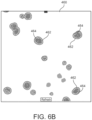
- FIG. 6B shows an example of an image 460 that may be generated and displayed in the region 304 of the display of the user computer 208 after undertaking the image analysis step specified using the panel 450. As shown in the image, objects 462 and sub-objects 464 within such objects 462 have been identified.
- the panel 450 also generates a table shown in FIG. 6C of the volumes of the objects identified in the FIG. 6B . Such table may also be displayed on the display of the user computer 208 or downloaded thereto.
- Examples of three-dimensional image processing steps that may be specified using the panels described above include apply Mean, Gaussian, and similar filters in three-dimensions; convolve a three-dimensional kernel with a series of images that represent an three-dimensional volume; apply a two-dimensional mask to each plane of a series of images that represent a three-dimensional volume; generate a three-dimensional object map wherein a unique pixel intensity in each plane of a series of output images is associated with a unique object in a series of images; identify pixels of a first object and a second object in corresponding first and second adjacent planes that overlap or are adjacent across planes, and associate the pixels of the first object and the second object with a same unique identifier; crop a volume represented in a series of images to reduce the size of the input for further image analysis steps; connect objects between adjacent planes; and the like.
- measurements that may be taken using three-dimensional image processing steps that may be specified using the panels described above include measure volumes of three-dimensional objects, classify shapes of three-dimensional objects, measure a distance in three-dimensions between objects, measure distance in three-dimensions between a feature of an object and a center of such object, and the like.
- the series of images described herein above may be a series of images taken over time, and time instead of volume analysis may be undertake using the image analysis system 200.
- Such analysis may be used to automatically track the position and velocity of an object in the field of view of the image capture device 110. Further, characteristics such as size, intensity, shape and similar features as the object moves in the field of view and changes in such characteristics may also be measured using the image analysis system 200 described above.
- any combination of hardware and/or software may be used to implement the image analysis system described herein. It will be understood and appreciated that one or more of the processes, sub-processes, and process steps described in connection with FIGS. 1-6C may be performed by hardware, software, or a combination of hardware and software on one or more electronic or digitally-controlled devices.
- the software may reside in a software memory (not shown) in a suitable electronic processing component or system such as, for example, one or more of the functional systems, controllers, devices, components, modules, or sub-modules schematically depicted in FIGS. 1-6C .
- the software memory may include an ordered listing of executable instructions for implementing logical functions (that is, "logic” that may be implemented in digital form such as digital circuitry or source code, or in analog form such as analog source such as an analog electrical, sound, or video signal).
- the instructions may be executed within a processing module or controller (e.g., the image acquisition module 202, the user interface module 206, and the image analysis module 208 of FIG. 2 ), which includes, for example, one or more microprocessors, general purpose processors, combinations of processors, digital signal processors (DSPs), field programmable gate arrays (FPGAs), or application-specific integrated circuits (ASICs).
- a processing module or controller e.g., the image acquisition module 202, the user interface module 206, and the image analysis module 208 of FIG. 2 ), which includes, for example, one or more microprocessors, general purpose processors, combinations of processors, digital signal processors (DSPs), field programmable gate arrays (FPGAs), or application-
- schematic diagrams describe a logical division of functions having physical (hardware and/or software) implementations that are not limited by architecture or the physical layout of the functions.
- the example systems described in this application may be implemented in a variety of configurations and operate as hardware/software components in a single hardware/software unit, or in separate hardware/software units.
- the executable instructions may be implemented as a computer program product having instructions stored therein which, when executed by a processing module of an electronic system, direct the electronic system to carry out the instructions.
- the computer program product may be selectively embodied in any non-transitory computer-readable storage medium for use by or in connection with an instruction execution system, apparatus, or device, such as a electronic computer-based system, processor-containing system, or other system that may selectively fetch the instructions from the instruction execution system, apparatus, or device and execute the instructions.
- computer-readable storage medium is any non-transitory means that may store the program for use by or in connection with the instruction execution system, apparatus, or device.
- the non-transitory computer-readable storage medium may selectively be, for example, an electronic, magnetic, optical, electromagnetic, infrared, or semiconductor system, apparatus, or device.
- a non-exhaustive list of more specific examples of non-transitory computer readable media include: an electrical connection having one or more wires (electronic); a portable computer diskette (magnetic); a random access, i.e., volatile, memory (electronic); a read-only memory (electronic); an erasable programmable read only memory such as, for example, Flash memory (electronic); a compact disc memory such as, for example, CD-ROM, CD-R, CD-RW (optical); and digital versatile disc memory, i.e., DVD (optical).
- receiving and transmitting of signals or data means that two or more systems, devices, components, modules, or sub-modules are capable of communicating with each other via signals that travel over some type of signal path.
- the signals may be communication, power, data, or energy signals, which may communicate information, power, or energy from a first system, device, component, module, or sub-module to a second system, device, component, module, or sub-module along a signal path between the first and second system, device, component, module, or sub-module.
- the signal paths may include physical, electrical, magnetic, electromagnetic, electrochemical, optical, wired, or wireless connections.
- the signal paths may also include additional systems, devices, components, modules, or sub-modules between the first and second system, device, component, module, or sub-module.
Landscapes
- Engineering & Computer Science (AREA)
- Physics & Mathematics (AREA)
- Multimedia (AREA)
- General Physics & Mathematics (AREA)
- Theoretical Computer Science (AREA)
- General Health & Medical Sciences (AREA)
- Health & Medical Sciences (AREA)
- Molecular Biology (AREA)
- Biomedical Technology (AREA)
- Life Sciences & Earth Sciences (AREA)
- Computer Vision & Pattern Recognition (AREA)
- Chemical & Material Sciences (AREA)
- Quality & Reliability (AREA)
- Analytical Chemistry (AREA)
- Optics & Photonics (AREA)
- Radiology & Medical Imaging (AREA)
- Nuclear Medicine, Radiotherapy & Molecular Imaging (AREA)
- Medical Informatics (AREA)
- Image Processing (AREA)
- Apparatus Associated With Microorganisms And Enzymes (AREA)
- Image Analysis (AREA)
- Investigating Or Analysing Biological Materials (AREA)
- Investigating Or Analysing Materials By Optical Means (AREA)
- Microscoopes, Condenser (AREA)
Description
- The present subject matter relates to high-content imaging systems and more particularly, to a system to analyze multi-dimensional data generated using such systems.
- A high-content imaging system (HCIS) may be used to obtain a microscopy image of a biological sample. Such image may include a number of cells against a background field. Further, the HCIS may be used to obtain a series of microscopy images of the biological sample, wherein, for example, each image is obtained using a different focus point. Such series of microscopy images may be combined to develop a three-dimensional view of the biological sample. Such series of microscopy images may also be analyzed to segment and identify a portion of each such image that is associated with a particular cell. Such portions may then be combined to form a three-dimensional view of the particular cell, analyzed further to identify organelles within the three-dimensional cell body, and/or develop three-dimensional statistics of the three-dimensional cell body and/or the organelles therein.
- A researcher may want to obtain statistics of cells that are present in the microscopy image or series of microscopy images. Such statistics may include a count of how may cells of a particular cell type are present in the image, the range of sizes (e.g., dimensions, volumes and surface areas) of such cells, the mean, median and mode of the sizes of such cells, how well the cell conforms to particular shape (e.g., sphericity), and the like. Further, the images may be analyzed to identify organelles within cells identified in such images and the statistics of such organelles may also be developed. Before any such statistics can be calculated, cells in the microscopy image must be segmented from the background and also from any debris present in the microscopy image.
- An interactive image analysis system may be used to specify a sequence of image analysis steps and parameters for each step. Examples of image analysis steps include, for example, select an image captured using a particular illumination source, threshold the image, and apply one or more filters to the image. Example filters may include unsharp mask, a smoothing filter, and the like. After the sequence of image analysis steps and corresponding parameters are specified, measurements may be taken of the image that results when the specified the image analysis steps are applied. Such measurements include a count of different types of objects (e.g., cells or components of cells) that are present in the resulting image. Cohen et al.,
U.S. Patent No. 8,577,079 , entitled "IMAGE PROCESSING SYSTEM PROVIDING SELECTIVE ARRANGEMENT AND CONFIGURATION FOR AN IMAGE ANALYSIS SEQUENCE," describes one such computer-implemented system for processing a selected image or series of images using multiple processing operations. -
US 2013/0058524 A1 suggests a computer-implemented method of processing a selected image using multiple processing operations. Therefore, an image analysis sequence having multiple processing steps is constructed. The image analysis sequence is constructed in response to receipt of multiple processing operation selections from the processing operation library. Individual processing steps in the image analysis sequence are associated with a processing operation that is indicated in a corresponding processing operation selection. The processing steps are arranged in response to receipt of arrangement information that relates to a selective arrangement of the processing steps. At least one of the processing steps in the image analysis sequence is configured such that the processing operation associated with the processing step processes a specified input image to generate an output image when the processing step is performed. A display signal is generated for display of the output image at a display device. The processing steps may be executed within a processing module, which includes, for example, one or more microprocessors. - The invention is defined in
claims - According to one aspect, a system for analyzing of multi-dimensional images includes a high content imaging system having an image capture device. An image acquisition module receives a first series of images of a biological sample captured by the image capture device, and the first series of images includes a sequence of image planes. A human interface module receives, from a user computer, specifications of a first image analysis step and a second image analysis step. The first image analysis step specifies a first image processing operation that processes an image plane of a series of images in accordance with at least another image plane of the series of images and the second image analysis step specifies a second image processing operation that processes each image plane of a series of images independently of the other image planes of the series. An image analysis module having a plurality of processors operating in parallel processes the first series of images in accordance with the first image processing step to generate a first output series of images, and processes the first series of images in accordance with second image processing step to generate a second output series of images. The human interface module displays at least one image plane of the first output series of images and 20 at least one image plane of the second output series of images on a display associated with the user computer. Further features are specified in
claim 1. - According to another aspect, a method for analyzing multi-dimensional images includes receiving receives a first series of images of a biological sample captured by the image capture device of a high content imaging system, wherein the first series of images comprises a sequence of image planes. The method also includes the steps of receiving from a user computer specifications of a first image analysis step and a second image analysis step, processing the first series of images in accordance with the first image processing step to generate a first output series of images, and processing the first series of images in accordance with second image processing step to generate a second output series of images. The first image analysis step specifies a first image processing operation that processes an image plane of a series of images in accordance with at least another image plane of the series of images and the second image analysis step specifies a second image processing operation that processes each image plane of a series of images independently of the other image planes of the series. Further, the method includes the step of displaying at least one image plane of the first output series of images and at least one image plane of the second output series of images on a display associated with the user computer. Further features are specified in
claim 6. - Other aspects and advantages will become apparent upon consideration of the following detailed description and the attached drawings wherein like numerals designate like structures throughout the specification.
-
-
FIG. 1 is a block diagram of a high-content imaging system in accordance with the present disclosure; -
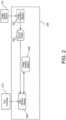
FIG. 2 is a block diagram of an image analysis system for analyzing multidimensional images captured using the high-content imaging system ofFIG. 1 ; -
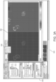
FIGS. 3A-3C are screens displayed by the image analysis system ofFIG. 2 ; -
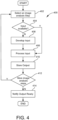
FIG. 4 is a flowchart of processing undertaken by an image analysis module of the image analysis system ofFIG. 2 ; -
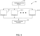
FIG. 5 is a block diagram of an embodiment of an image analysis module of the image analysis system ofFIG. 2 ; -
FIGS. 6A is a portion of a screen displayed by the image analysis system ofFIG. 2 that allows specification of an image analysis step; -
FIG. 6B is an example image generated by the image analysis module in accordance with the image analysis step specified by the screen ofFIG. 6A ; and -
FIG. 6C is an example table of measurements generated by the image analysis module in accordance with the image analysis step specified by the screen ofFIG. 6A . - Referring to
FIG. 1 , as will be apparent to those who have skill in the art, anHCIS 100 may include anX-Y stage 102, one or moreobjective lenses 104, one ormore illumination sources 106, one ormore filters 108, animage capture device 110, and acontroller 112. The HCIS 100 may also include one ormore mirrors 114 that direct light from theillumination source 106 to asample tray 116 that may be disposed on theX-Y stage 102, and fromsuch sample tray 116 to theimage capture device 110. Typically, thesample tray 116 includes a plurality ofwells 118, and samples (for example, biological cells) to be imaged by theHCIS 100 may be disposed in each such well 118. - Although,
FIG. 1 shows the light from theillumination source 106 reflected fromsample tray 116 reaching theimage capture device 110, it should be apparent that additional mirrors (not shown) may be used so that light from theillumination source 106 is transmitted through thesample tray 116 and directed toward theimage capture device 110. Further, it should be apparent that in some cases no illumination from theillumination source 106 may be necessary to image the samples in the sample tray 116 (for example, if the samples emit light or if the samples include radioactive components). In some embodiments, light from the illumination source may be transmitted through the samples in thesample tray 116, and the samples refract and/or absorb the transmitted light to produce light that is imaged. - During operation, the
sample tray 116 may be placed, either manually or robotically, on theX-Y stage 102. In addition, thecontroller 112 may configure theHCIS 100 to use a combination of a particularobjective lens 104, illumination generated by theillumination source 106, and/orfilter 108. For example, thecontroller 112 may operate positioning devices (not shown) to place a selectedobjective lens 104 and, optionally, a selectedfilter 108 in the light path between thesample tray 116 and theimage capture device 110. Thecontroller 112 may also direct theillumination source 106 to illuminate thesample tray 116 with particular wavelengths of light. The samples in thesample tray 116 may contain molecules that fluoresce, either naturally occurring molecules, or molecules produced or present within the samples due to treatment. The wavelength illuminating the sample may be the excitation wavelengths associated with such fluorescent molecules, and the imaging capture device will capture only the - emission spectrum of such fluorescent materials. One or more wavelengths may used serially or simultaneously to illuminate the same samples and produce images
- To obtain a series of images at different focal positions, the
controller 112 operates afocus mechanism 120 so that theimage capture device 110 may obtain in-focus images of the sample disposed in thesample tray 116 at each such focal position. - Referring to
FIG. 2 , a multi-dimensionalimage analysis system 200 for specifying a sequence of image analysis steps for processing two-dimensional and three-dimensional images from anHCIS 100 includes animage acquisition module 202 in communications with theimage capture device 112 of theHCIS 100. - The
image acquisition module 202 directs thecontroller 112 to capture a series of images of a biological sample at various focal positions. In one embodiment, theimage acquisition module 202 may direct thecontroller 112 to operate thefocus mechanism 120 and theimage capture device 112 to capture a series of between 10 and 150 successive images of the sample. To obtain a low-resolution three-dimensional representation of the sample, theimage acquisition module 202 may direct thecontroller 112 to adjust the focal position by approximately 50 microns between successive images. To obtain a high-resolution three-dimensional representation of the sample, theimage acquisition module 202 may direct thecontroller 112 to adjust the focal position by between approximately 3 microns and 5 microns between successive images. For an even, higher-resolution three-dimensional representation of the sample, theimage acquisition module 202 may direct thecontroller 112 to adjust the focal position by between 0.5 microns and 1 micron between successive images. - Further, the
image acquisition module 202 may direct the controller to capture multiple series of images, wherein each series of images is captured using a different combination of anillumination source 106,filter 108, andobjective lens 104. - The
image acquisition module 202 receives each series of successive source images of the sample from theimage capture device 112 and stores such images in a sourceimages data store 204. Each series of source images is considered a three-dimensional representation of the volume that includes the biological sample, and each source image of the series is considered a two-dimensional plane (or slice) of the three-dimensional volume. The biological sample may include one or more cells. Larger cells may be represented in all of the planes of the three-dimensional representation, and smaller cells may be represented in only some planes of the three-dimensional representation. - After the series of source images are stored in the source
images data store 204, auser interface module 206 allows an operator to use auser computer 208 to select one or more of the series of source images. The selected series is displayed on the screen of theuser computer 208. The user may specify to theuser interface module 206, a sequence of three-dimensional and two-dimensional image analysis steps to perform on the displayed series of images. An image or series of images that is developed after the sequence of image analysis steps have been undertaken is displayed on the screen of theuser computer 208. - Referring to
FIGS. 3A-3C , theuser interface module 206 displays on thescreen 300 of the user computer 208 aregion 302 in which panels for specifying image analysis steps may be displayed, aregion 304 in which one or more images may be displayed, and amenu 306 of available image analysis steps. - Referring to
FIG. 3B , selecting a menu item in themenu 306 displays a corresponding panel 308. Each panel is associated with a particular image analysis step. The panel includes a pop-up menu 310 from which an input (or source) plane or a series of images may be selected. The panel also includes a text box 312 in which the user may enter an identifier associated with an output (or result) plane or series of images that result from applying the particular image analysis step to the selected input plane or series of images. - The pop-up menu 310 presents identifiers associated with each series of images captured by the image capture device using different imaging parameters or the identifier associated with the output of another panel 308.
- Each panel 308 also includes one or more text-boxes and/or selection boxes 314 to specify parameters associated with the particular image analysis step specified using such panel 308. For example, the
panel 308a is associated with an image analysis step of "Find Spherical Objects," and uses as input a series of images associated with an identifier DAPI (310a). The panel includes text boxes 314 for specifying a minimum and maximum width of spherical objects, and intensity of such objects compared to the background, and a minimum and maximum number of planes each identified object may span. The result of applying the image analysis step specified by thepanel 308a is associated with an output series of images named "Find Spherical Objects" (312a). - Further, the
panel 308b is associated with an image analysis step of "Count Nuclei Objects" also in the series of images associated with the identifier DAPI (3 10b). The result of thepanel 308b is associated with the identifier "Count Nuclei Objects" (312b). - The
panel 308c uses as an input an image associated with the identifier "Count Nuclei Objects" (310c), which is the output of the image analysis step specified by thepanel 308b, and generates an output series of images associated with an identifier "Nuclei" (312c). - Because the inputs of the
panel system 200 may undertake the image analysis steps identified by such panels concurrently. Thesystem 200 undertakes the image analysis steps identified by thepanel 308c only after the output of thepanel 308b is available. - Further, the
panels panel 308b specifies a two-dimensional image analysis steps that analyzes each plane of the series separately. - The count nuclei image analysis step specified by
panel 308b analyzes the pixels in an image plane to separate pixels that are associated with an object from pixels that are part of the background. The image may be processed (for example, smoothed, thresholded, and analyzed) to associate connected pixels that are too small with the background and break up connected pixels that specify one object that is too large into separate objects. Each image plane is processed independently in accordance with the image analysis step specified bypanel 308b. - In contrast, the connect by best match image analysis step specified by
panel 308c analyzes multiple planes to identify object pixels in such planes that are all associated with the same object in three dimensions. The connect by best match image analysis step identifies pixels that are connected across image planes and associates such identified pixel with the same object. The connect by best match image analysis step associates an object-id with each object in an image plane identified by the count nuclei image analysis step. An object map image plane is created from each image plane of the series of images output by the count nuclei image analysis step specified bypanel 308b, and the value of each pixel of the object map image plane that corresponds to an object pixel in the image plane is set to object-id of the object. - Thereafter, pixels associated with an object in each object map image plane are compared to pixels associated with objects in other object map image planes to determine if such pixels of these different planes are associated with the same object (i.e., connected across planes). If so, these pixels of the different planes are assigned the same object id. The result of such analysis is an object map series of images that identifies individual objects in the captured series of image in three dimensions. Such object map series of images may be analyzed to measure three-dimensional characteristics (such as sphericity, shape, volume, and the like) of the objects of the captured series of images.
- First connected pixels in a first object map image plane and second connected pixels in a second object map image plane are associated with the same object (and assigned the same object-id) if the first and second connected pixels at least partially overlap. Additionally, the first and the second connect pixels are associated with the same object if such pixels are within a pre-determined distance (in three-dimensions) from one another and if the differences in intensities of the corresponding pixels in the series of images are within a predetermined threshold.
- Further, the object map series of images may be analyzed to make sure that connected pixels in each object map plane is associated with at most one object. Further, if the first pixels of the first object map plane and second pixels of the second object plane are associated with a particular object (i.e., have the same object id) and if there are more than a predetermined number of intervening planes between the first and the second object map planes that do not have any pixels associated with the particular object, the first pixels and second pixels will be associated with different objects (i.e., given different object-ids). As should be apparent, the image analysis step specified by the
panel 308c requires analysis of multiple image planes, and each image plane may not be processed independently from other image planes. - Referring to
FIG. 3C , the user-interface displays in theregion 304 the results of the image analysis steps specified in theregion 300. Applying the series of image analysis steps results in one or more image processed series of images, and one plane of such image-processed series of images is displayed in one or morecorresponding regions 350. In some embodiments, the user may hide the results of particular image processing steps, determine if only one image plane is displayed, or specify display of a composite image generated from the series of image planes. - A
slider 352 is also displayed, for example, adjacent to one of the images displayed in theregions 304. Adjusting theslider 352 by one unit upward displays subsequent plane from the series of source images in theregion 304. If multiple planes, each from a different series of images, are displayed in theregion 304, adjusting theslider 352 selects a subsequent or preceding plane of each such series to display. Similarly, adjusting theslider 306 downward displays preceding planes in thepanels - A
threshold slider 354 may be displayed adjacent to some images displayed in theregion 300, and adjustingsuch slider 354 dynamically adjusts the brightness of the displayed image based on intensity. - Each panel 308 includes a button 316 and selecting such button immediately undertakes the image-processing step specified by such panel. If such image-processing step requires an input that is an output of another panel to be generated, the
image processing system 200 generates such output. The image or series of images that results from such image-processing step is displayed immediately in theregion 304 of thescreen 300 of theuser computer 208. In this manner, the user may interactively adjust parameters and select the order in which multiple image-processing steps are undertaken in two-dimensions and three-dimensions to analyze the biological sample. - Referring once again to
FIG. 3B , the image analysis steps defined in theregion 300 may be associated with an identifier using thetext box 318 and saved. All of the image analysis steps defined in the 300 may executed by selecting abutton 320. Further, such image analysis steps may be executed without update to the images displayed in the region 304 (i.e., in a batch mode) to process one or more series of images captured using theHCIS 100. - Referring to
FIGS. 2 and3B , when the user presses the button 316 or thebutton 320 theuser interface module 206 provides the specified image analysis steps and the user supplied parameters associated with such steps to theimage analysis module 208. -
FIG. 4 illustrates aflowchart 400 of the steps undertaken by theimage analysis module 208. Atstep 402, theimage analysis module 208 selects one of the steps specified by the user. Atstep 404, theimage analysis module 208 determines if the input image or series of images is available (i.e., has been created). If so, theimage analysis module 208 proceeds to step 406. Otherwise, atstep 408, theimage analysis module 208 undertakes the image analysis step necessary to develop the input, and then proceeds to step 406. - At
step 406, theimage analysis module 208 processes the input in accordance with the parameters associated with the image analysis step selected atstep 402. Atstep 410, theimage analysis module 208 stores the results of undertaking the image analysis step. Atstep 412, theimage analysis module 208 determines if there are any image analysis steps specified by the user that have not been undertaken, and if so, proceeds to step 402. Otherwise theimage analysis module 208 notifies the user interface module that the output image or series of images are ready, atstep 414, and exits. - Referring also to
FIG. 5 , some image processing steps may be parallelizable. In such cases, atstep 208, adistribution processor 420 of theimage processing module 208 may supply the image processing function associated with the image processing step and the parameters of the image processing step to each one of a plurality of processors 422. In addition, thedistribution processor 420 may assign a unique portion of the input (either a plane of a series of images or a portion of a plane) to each one of a plurality of processors 422. The plurality of processors 422 undertake the image analysis step on the unique portion of the input assigned thereto and provide the result of such image analysis step to anoutput combination processor 424. Theoutput combination processor 424 combines the output generated by each processor 422 to create the output of the image analysis step. - The
image analysis system 200 may allow the user to specify multiple input sources to use in an image analysis step. Referring toFIGS. 6A and6B , apanel 450 associated with a measure volume image analysis step that includes three pull downmenus menu 452a specifies a first input to this image analysis step to be the output of the image analysis step specified using thepanel 308a (FIG. 3B ), the pull downmenu 452b species a second input to be DAPI, and the pull downmenu 452c specifies a third input to be FITC. In this example, DAPI and FITC are different imaging conditions under which separate series of images of the biological sample were captured. The DAPI series of images may be used to identify cell or spheroids of cells. The FITC series of image may be used to identify nuclei within cells. - The image analysis step specified in the
panel 450 applies the input specified using the pull downmenu 452a as a mask to the inputs specified using the pull down menu 450b and 450c to identify both object and nuclei in such objects. In this example, each plane of the series "Find Spherical Objects" selected using the pull-down menu 452a is masked with both a corresponding plane of the series "DAPI" selected using the pull-down menu 452b and a corresponding plane of the series "FITC" selected using the pull-down menu 452c. The corresponding planes of the two series of images that result from the two masking operations are merged into a single plane of an output of series of images that results from this step. -
FIG. 6B shows an example of animage 460 that may be generated and displayed in theregion 304 of the display of theuser computer 208 after undertaking the image analysis step specified using thepanel 450. As shown in the image, objects 462 andsub-objects 464 withinsuch objects 462 have been identified. - The
panel 450 also generates a table shown inFIG. 6C of the volumes of the objects identified in theFIG. 6B . Such table may also be displayed on the display of theuser computer 208 or downloaded thereto. - Examples of three-dimensional image processing steps that may be specified using the panels described above include apply Mean, Gaussian, and similar filters in three-dimensions; convolve a three-dimensional kernel with a series of images that represent an three-dimensional volume; apply a two-dimensional mask to each plane of a series of images that represent a three-dimensional volume; generate a three-dimensional object map wherein a unique pixel intensity in each plane of a series of output images is associated with a unique object in a series of images; identify pixels of a first object and a second object in corresponding first and second adjacent planes that overlap or are adjacent across planes, and associate the pixels of the first object and the second object with a same unique identifier; crop a volume represented in a series of images to reduce the size of the input for further image analysis steps; connect objects between adjacent planes; and the like.
- Examples of measurements that may be taken using three-dimensional image processing steps that may be specified using the panels described above include measure volumes of three-dimensional objects, classify shapes of three-dimensional objects, measure a distance in three-dimensions between objects, measure distance in three-dimensions between a feature of an object and a center of such object, and the like.
- According to an embodiment being not part of the claimed invention, the series of images described herein above may be a series of images taken over time, and time instead of volume analysis may be undertake using the
image analysis system 200. Such analysis may be used to automatically track the position and velocity of an object in the field of view of theimage capture device 110. Further, characteristics such as size, intensity, shape and similar features as the object moves in the field of view and changes in such characteristics may also be measured using theimage analysis system 200 described above. - It should be apparent to those who have skill in the art that any combination of hardware and/or software may be used to implement the image analysis system described herein. It will be understood and appreciated that one or more of the processes, sub-processes, and process steps described in connection with
FIGS. 1-6C may be performed by hardware, software, or a combination of hardware and software on one or more electronic or digitally-controlled devices. The software may reside in a software memory (not shown) in a suitable electronic processing component or system such as, for example, one or more of the functional systems, controllers, devices, components, modules, or sub-modules schematically depicted inFIGS. 1-6C . The software memory may include an ordered listing of executable instructions for implementing logical functions (that is, "logic" that may be implemented in digital form such as digital circuitry or source code, or in analog form such as analog source such as an analog electrical, sound, or video signal). The instructions may be executed within a processing module or controller (e.g., theimage acquisition module 202, theuser interface module 206, and theimage analysis module 208 ofFIG. 2 ), which includes, for example, one or more microprocessors, general purpose processors, combinations of processors, digital signal processors (DSPs), field programmable gate arrays (FPGAs), or application-specific integrated circuits (ASICs). Further, the schematic diagrams describe a logical division of functions having physical (hardware and/or software) implementations that are not limited by architecture or the physical layout of the functions. The example systems described in this application may be implemented in a variety of configurations and operate as hardware/software components in a single hardware/software unit, or in separate hardware/software units. - The executable instructions may be implemented as a computer program product having instructions stored therein which, when executed by a processing module of an electronic system, direct the electronic system to carry out the instructions. The computer program product may be selectively embodied in any non-transitory computer-readable storage medium for use by or in connection with an instruction execution system, apparatus, or device, such as a electronic computer-based system, processor-containing system, or other system that may selectively fetch the instructions from the instruction execution system, apparatus, or device and execute the instructions. In the context of this document, computer-readable storage medium is any non-transitory means that may store the program for use by or in connection with the instruction execution system, apparatus, or device. The non-transitory computer-readable storage medium may selectively be, for example, an electronic, magnetic, optical, electromagnetic, infrared, or semiconductor system, apparatus, or device. A non-exhaustive list of more specific examples of non-transitory computer readable media include: an electrical connection having one or more wires (electronic); a portable computer diskette (magnetic); a random access, i.e., volatile, memory (electronic); a read-only memory (electronic); an erasable programmable read only memory such as, for example, Flash memory (electronic); a compact disc memory such as, for example, CD-ROM, CD-R, CD-RW (optical); and digital versatile disc memory, i.e., DVD (optical).
- It will also be understood that receiving and transmitting of signals or data as used in this document means that two or more systems, devices, components, modules, or sub-modules are capable of communicating with each other via signals that travel over some type of signal path. The signals may be communication, power, data, or energy signals, which may communicate information, power, or energy from a first system, device, component, module, or sub-module to a second system, device, component, module, or sub-module along a signal path between the first and second system, device, component, module, or sub-module. The signal paths may include physical, electrical, magnetic, electromagnetic, electrochemical, optical, wired, or wireless connections. The signal paths may also include additional systems, devices, components, modules, or sub-modules between the first and second system, device, component, module, or sub-module.
- The use of the terms "a" and "an" and "the" and similar references in the context of describing the invention (especially in the context of the following claims) are to be construed to cover both the singular and the plural, unless otherwise indicated herein or clearly contradicted by context. Recitation of ranges of values herein are merely intended to serve as a shorthand method of referring individually to each separate value falling within the range, unless otherwise indicated herein, and each separate value is incorporated into the specification as if it were individually recited herein. All methods described herein can be performed in any suitable order unless otherwise indicated herein or otherwise clearly contradicted by context. The use of any and all examples, or exemplary language (e.g., "such as") provided herein, is intended merely to better illuminate the disclosure and does not pose a limitation on the scope of the disclosure unless otherwise claimed. No language in the specification should be construed as indicating any non-claimed element as essential to the practice of the disclosure.
Numerous modifications to the present disclosure will be apparent to those skilled in the art in view of the foregoing description. It should be understood that the illustrated embodiments are exemplary only, and should not be taken as limiting the scope of the disclosure.
Claims (11)
- A system for analyzing multi-dimensional images, comprising:a high content imaging system (100), wherein the high content image system includes an image capture device (110);an image acquisition module (200) that is adapted to receive a first series of images of a biological sample captured by the image capture device (110), wherein the first series of images is a three-dimensional representation of the volume including the biological sample, and each image of the first series of images is a two-dimensional plane of the three-dimensional volume;a human interface module (206) that is adapted to receive, from a user computer (210), specifications of a first image analysis step, a second image analysis step and a third image analysis step, wherein the first image analysis step specifies a first image processing operation that processes an image plane of a series of images in accordance with at least another image plane of the series of images, the second image analysis step specifies a second image processing operation that processes each image plane of a series of images independently of the other image planes of the series, and the third image analysis step specifies a third image processing operation; andan image analysis module (208) comprising a plurality of processors (422) adapted to operate in parallel, which is adapted to process the first series of images in accordance with the first image processing step to generate a first output series of images, is adapted to process the first series of images in accordance with second image processing step to generate a second output series of images, and is adapted to process the second output series of images in accordance with the third image processing step to generate a third output series of images;wherein the human interface module (206) is adapted to display at least one image plane of the first output series of images and at least one image plane of the second output series of images on a display associated with the user computer (210)wherein the second image processing operation further comprises analyzing the pixels of each image plane of the series of images to separate pixels that are associated with an object from that are part of the background; andwherein the image analysis module (208) is adapted to implement the third image processing operation that further comprises:creating an object map image plane from each image plane of the second output series of images and setting a value of each pixel of the object map image plane that corresponds to an object pixel in the image plane to an object-id,comparing pixels associated with an object in each object map image plane to pixels associated with objects in other object map image planes to determine if such pixels of the object map image planes are associated with the same object; andassigning the same object-id to the pixels of the object map image planes associated with the same object if these pixels of the object image planes at least partially overlap and are within a predetermined distance in three-dimensions from one another and if the differences in intensities of the corresponding pixels in the series of images are within a predetermined threshold.
- The system of claim 1, wherein the plurality of processors (422) are adapted to process in parallel each image plane of the first series of images in accordance with the second image analysis step to generate the second output series of images.
- The system of claim 1, wherein the human interface module (206) is adapted to display the first output series of images, thereafter is adapted to receive a change in a parameter of the specification of the first image analysis step, and the image analysis module (208) is adapted to process the first series of images in accordance with the specification of the first image analysis step and the changed parameter to generate an updated first output series of images.
- The system of claim 1, wherein the image acquisition module (200) is adapted to receive a second series of images of the biological sample, and the human interface module (206) is adapted to receive a specification of a fourth image analysis step, wherein the first series of images and the second series of images are acquired under different illumination conditions, and the fourth image analysis step specifies an image processing operation having the first series of images, the second series of images, and the first output series of images as inputs, wherein in particular the image analysis module (208), in accordance with the fourth image analysis step, is adapted:to apply the first output series of images as a mask to the first series of images to generate a first masked series of images,to apply the first output series of images as a mask to the second series of images to generate a second masked series of images, andto combine the first masked series of images and the second masked series of images to develop a fourth output series of images.
- The system of claim 1, wherein the first image processing step specifies:undertaking one of applying a three-dimensional filter to the first series of images,applying a mask to each image plane of the first series of images,generating an object map from the first series of images,identifying pixels of a first object that spans a plurality of image planes of the first series of images,cropping the first series of images in three-dimensions, andmeasuring characteristics of each one of a plurality of three-dimensional objects represented in the first series of images.
- A method for analyzing multi-dimensional images, comprising:receiving a first series of images of a biological sample captured by an image capture device (110) of a high content imaging system (100), wherein the first series of images is a three-dimensional representation of the volume including the biological sample, and each image of the first series of images is a two-dimensional plane of the three-dimensional volume;receiving from, a user computer (210), specifications of a first image analysis step, a second image analysis step and a third image analysis step, wherein the first image analysis step specifies a first image processing operation that processes an image plane of a series of images in accordance with at least another image plane of the series of images, the second image analysis step specifies a second image processing operation that processes each image plane of a series of images independently of other image planes of the series, and the third image analysis step specifies a third image processing operation;processing the first series of images in accordance with the first image processing step to generate a first output series of images;processing the first series of images in accordance with the second image processing step to generate a second output series of images;processing the second output series of images in accordance with the third image processing step to generate a third output series of images; anddisplaying at least one image plane of the first output series of images and at least one image plane of the second output series of images on a display associated with the user computer (210),wherein the second image processing operation further comprises analyzing the pixels of each image plane of the series of images to separate pixels that are associated with an object from that are part of the background; and wherein the third image processing operation further comprises:creating an object map image plane from each image plane of the second output series of images and setting a value of each pixel of the object map image plane that corresponds to an object pixel in the image plane to an object-id,comparing pixels associated with an object in each object map image plane to pixels associated with objects in other object map image planes to determine if such pixels of the object map image planes are associated with the same object; andassigning the same object-id to the pixels of the object map image planes associated with the same object if these pixels of the object image planes at least partially overlap are within a pre-determined distance in three-dimensions from one another and if the differences in intensities of the corresponding pixels in the series of images are within a predetermined threshold.
- The method of claim 8, wherein processing the first series of images comprises operating a plurality of processors (422) to process in parallel each image plane of the first series of images in accordance with the second image analysis step to generate the second output series of images.
- The method of claim 8, further comprising displaying the first output series of images, thereafter receiving a change in a parameter of the specification of the first image analysis step, and processing the first series of images in accordance with the specification of the first image analysis step and the changed parameter to generate an updated first output series of images.
- The method of claim 8, further comprising receiving a second series of images of the biological sample wherein the first series of images and the second series of images are captured under different illumination conditions, and receiving a specification of a fourth image analysis step, wherein the fourth image analysis step specifies an image processing operation having the first series of images, the second series of images, and the first output series of images as inputs.
- The method of claim 12, further comprising applying in accordance with the fourth image analysis step the first output series of images as a mask to the first series of images to generate a first masked series of images, applying the first output series of images as mask to the second series of images to generate a second masked series of images, and combining the first masked series of images and the second masked series of images to develop a fourth output series of images.
- The system of claim 1 or the method of claim 8, further comprising capturing each image plane of the first series of images at a different focus point relative to the biological sample.
Applications Claiming Priority (2)
| Application Number | Priority Date | Filing Date | Title |
|---|---|---|---|
| US15/019,411 US9928403B2 (en) | 2016-02-09 | 2016-02-09 | System and method for image analysis of multi-dimensional data |
| PCT/US2017/016126 WO2017139160A1 (en) | 2016-02-09 | 2017-02-02 | System and method for image analysis of multi-dimensional data |
Publications (3)
| Publication Number | Publication Date |
|---|---|
| EP3414740A1 EP3414740A1 (en) | 2018-12-19 |
| EP3414740A4 EP3414740A4 (en) | 2019-10-30 |
| EP3414740B1 true EP3414740B1 (en) | 2024-05-29 |
Family
ID=59497805
Family Applications (1)
| Application Number | Title | Priority Date | Filing Date |
|---|---|---|---|
| EP17750588.0A Active EP3414740B1 (en) | 2016-02-09 | 2017-02-02 | System and method for image analysis of multi-dimensional data |
Country Status (5)
| Country | Link |
|---|---|
| US (3) | US9928403B2 (en) |
| EP (1) | EP3414740B1 (en) |
| JP (1) | JP6881878B2 (en) |
| CN (2) | CN115511866B (en) |
| WO (1) | WO2017139160A1 (en) |
Families Citing this family (6)
| Publication number | Priority date | Publication date | Assignee | Title |
|---|---|---|---|---|
| US9928403B2 (en) * | 2016-02-09 | 2018-03-27 | Molecular Devices, Llc | System and method for image analysis of multi-dimensional data |
| US20200005014A1 (en) * | 2017-01-05 | 2020-01-02 | Konica Minolta, Inc. | Non-transitory computer-readable recording medium storing image analysis program and image analysis method |
| CN110914666A (en) * | 2017-05-19 | 2020-03-24 | 兴盛生物科技股份有限公司 | System and method for counting cells |
| CN109034110A (en) * | 2018-08-17 | 2018-12-18 | 潘小亮 | Gun battle movie computer classes method |
| US11068694B2 (en) | 2019-01-23 | 2021-07-20 | Molecular Devices, Llc | Image analysis system and method of using the image analysis system |
| JP7748457B2 (en) | 2020-09-21 | 2025-10-02 | モレキュラー デバイシーズ, エルエルシー | Method and system for developing imaging configurations to optimize performance of a microscopy system |
Family Cites Families (41)
| Publication number | Priority date | Publication date | Assignee | Title |
|---|---|---|---|---|
| US5936731A (en) * | 1991-02-22 | 1999-08-10 | Applied Spectral Imaging Ltd. | Method for simultaneous detection of multiple fluorophores for in situ hybridization and chromosome painting |
| WO1999008233A1 (en) * | 1997-08-07 | 1999-02-18 | Imaging Research Inc. | A digital imaging system for assays in well plates, gels and blots |
| US6519355B2 (en) * | 2001-03-28 | 2003-02-11 | Alan C. Nelson | Optical projection imaging system and method for automatically detecting cells having nuclear and cytoplasmic densitometric features associated with disease |
| GB0227160D0 (en) * | 2002-11-21 | 2002-12-24 | Qinetiq Ltd | Histological assessment of pleomorphism |
| US7298886B2 (en) * | 2003-09-05 | 2007-11-20 | 3M Innovative Properties Company | Counting biological agents on biological growth plates |
| US8045782B2 (en) * | 2004-12-07 | 2011-10-25 | Ge Healthcare Niagara, Inc. | Method of, and apparatus and computer software for, implementing image analysis protocols |
| US7512284B2 (en) * | 2005-03-29 | 2009-03-31 | General Electric Company | Volumetric image enhancement system and method |
| SE530750C2 (en) * | 2006-07-19 | 2008-09-02 | Hemocue Ab | A measuring device, a method and a computer program |
| US9697582B2 (en) * | 2006-11-16 | 2017-07-04 | Visiopharm A/S | Methods for obtaining and analyzing images |
| DE102007034854A1 (en) | 2007-07-24 | 2009-01-29 | Jpk Instruments Ag | Method and device for automated measurement and combination of image acquisition and force measurement |
| CN101981430B (en) * | 2008-03-26 | 2013-03-27 | 3M创新有限公司 | Spectral Analysis of Biological Growth Media |
| US20100268225A1 (en) | 2009-04-15 | 2010-10-21 | Tyco Healthcare Group Lp | Methods for Image Analysis and Visualization of Medical Image Data Suitable for Use in Assessing Tissue Ablation and Systems and Methods for Controlling Tissue Ablation Using Same |
| US8310531B2 (en) * | 2009-08-03 | 2012-11-13 | Genetix Corporation | Methods and apparatuses for processing fluorescence images |
| GB0913930D0 (en) | 2009-08-07 | 2009-09-16 | Ucl Business Plc | Apparatus and method for registering two medical images |
| JP5715132B2 (en) * | 2009-08-20 | 2015-05-07 | コーニンクレッカ フィリップス エヌ ヴェ | Method and system for image analysis |
| US8564623B2 (en) * | 2009-12-11 | 2013-10-22 | Molecular Devices, Llc | Integrated data visualization for multi-dimensional microscopy |
| KR101848508B1 (en) | 2011-01-25 | 2018-04-13 | 삼성에스디아이 주식회사 | System for image analysis and method thereof |
| US9297995B2 (en) * | 2011-02-11 | 2016-03-29 | University Of South Florida | Automatic stereological analysis of biological tissue including section thickness determination |
| JP5197785B2 (en) * | 2011-03-30 | 2013-05-15 | キヤノン株式会社 | Image processing apparatus, imaging system, and image processing system |
| AU2012271257B2 (en) * | 2011-06-17 | 2016-01-14 | Roche Diagnostics Hematology, Inc. | Systems and methods for sample display and review |
| JP5831018B2 (en) * | 2011-07-29 | 2015-12-09 | 富士通株式会社 | Biometric authentication device and method for adjusting user's hand position in biometric authentication device |
| US8731278B2 (en) * | 2011-08-15 | 2014-05-20 | Molecular Devices, Inc. | System and method for sectioning a microscopy image for parallel processing |
| US8577079B2 (en) | 2011-09-02 | 2013-11-05 | Molecular Devices, Llc | Image processing system providing selective arrangement and configuration for an image analysis sequence |
| JP5464244B2 (en) * | 2012-08-24 | 2014-04-09 | 富士ゼロックス株式会社 | Image processing apparatus, program, and image processing system |
| JP2014071207A (en) * | 2012-09-28 | 2014-04-21 | Canon Inc | Image processing apparatus, imaging system, and image processing system |
| JP6160187B2 (en) * | 2013-04-09 | 2017-07-12 | ソニー株式会社 | Analysis device, analysis program, and analysis system |
| EP2984629B1 (en) * | 2013-04-09 | 2018-07-18 | Koninklijke Philips N.V. | Layered two-dimensional projection generation and display |
| EP3019905B1 (en) * | 2013-04-30 | 2020-06-03 | Molecular Devices, LLC | Apparatus and method for generating in-focus images using parallel imaging in a microscopy system |
| US9055251B2 (en) * | 2013-09-24 | 2015-06-09 | Xerox Corporation | Image processing based on automatic image-type detection |
| JP6213146B2 (en) * | 2013-10-24 | 2017-10-18 | ソニー株式会社 | Information processing apparatus, recording medium, and information processing method |
| US10115199B2 (en) * | 2014-10-08 | 2018-10-30 | Decision Sciences International Corporation | Image based object locator |
| JP2015108837A (en) * | 2015-01-07 | 2015-06-11 | キヤノン株式会社 | Image processing apparatus and image processing method |
| US9754378B2 (en) * | 2016-01-21 | 2017-09-05 | Molecular Devices, Llc | System and method for segmentation of three-dimensional microscope images |
| US9928403B2 (en) * | 2016-02-09 | 2018-03-27 | Molecular Devices, Llc | System and method for image analysis of multi-dimensional data |
| KR102630227B1 (en) * | 2016-07-21 | 2024-01-29 | 한화비전 주식회사 | Surveillance Data Providing System and Method Thereof |
| CN106709930B (en) * | 2016-12-29 | 2020-03-31 | 上海联影医疗科技有限公司 | Method and device for segmenting interested volume of three-dimensional medical image |
| NL2020405B1 (en) * | 2018-02-08 | 2019-08-19 | Fugro N V | Method of and apparatus for analyzing images |
| CN108960202B (en) * | 2018-08-01 | 2022-05-10 | 京东方科技集团股份有限公司 | An intelligent shelf, system, and method for judging the stacking of commodities |
| US10929716B2 (en) * | 2018-09-12 | 2021-02-23 | Molecular Devices, Llc | System and method for label-free identification and classification of biological samples |
| US11068694B2 (en) * | 2019-01-23 | 2021-07-20 | Molecular Devices, Llc | Image analysis system and method of using the image analysis system |
| EP4078151A4 (en) * | 2019-12-17 | 2024-01-03 | Applied Materials, Inc. | SYSTEM AND METHOD FOR CAPTURE AND PROCESSING MULTIPLEXED FLUORESCENCE IN SITU HYBRIDIZATION IMAGES |
-
2016
- 2016-02-09 US US15/019,411 patent/US9928403B2/en active Active
-
2017
- 2017-02-02 JP JP2018541336A patent/JP6881878B2/en active Active
- 2017-02-02 WO PCT/US2017/016126 patent/WO2017139160A1/en not_active Ceased
- 2017-02-02 CN CN202211265366.2A patent/CN115511866B/en active Active
- 2017-02-02 CN CN201780009222.1A patent/CN108604375B/en active Active
- 2017-02-02 EP EP17750588.0A patent/EP3414740B1/en active Active
-
2018
- 2018-02-15 US US15/897,699 patent/US10706259B2/en active Active
-
2020
- 2020-06-05 US US16/894,267 patent/US11334743B2/en active Active
Also Published As
| Publication number | Publication date |
|---|---|
| US20170228865A1 (en) | 2017-08-10 |
| CN108604375B (en) | 2022-11-01 |
| EP3414740A1 (en) | 2018-12-19 |
| US11334743B2 (en) | 2022-05-17 |
| US9928403B2 (en) | 2018-03-27 |
| US20200311377A1 (en) | 2020-10-01 |
| CN115511866A (en) | 2022-12-23 |
| US10706259B2 (en) | 2020-07-07 |
| CN115511866B (en) | 2024-04-09 |
| US20180247102A1 (en) | 2018-08-30 |
| WO2017139160A1 (en) | 2017-08-17 |
| JP2019515362A (en) | 2019-06-06 |
| EP3414740A4 (en) | 2019-10-30 |
| CN108604375A (en) | 2018-09-28 |
| JP6881878B2 (en) | 2021-06-02 |
Similar Documents
| Publication | Publication Date | Title |
|---|---|---|
| US11334743B2 (en) | System and method for image analysis of multi-dimensional data | |
| US11645752B2 (en) | Image analysis system and method of using the image analysis system | |
| KR102273115B1 (en) | Method and system for classifying and identifying individual cells in a microscopy image | |
| EP3005293B1 (en) | Image adaptive physiologically plausible color separation | |
| US10169878B2 (en) | System and method for segmentation of three-dimensional microscope images | |
| CN112689756A (en) | System and method for label-free identification and classification of biological samples | |
| WO2017150194A1 (en) | Image processing device, image processing method, and program | |
| US20200106993A1 (en) | Method of controlling microscope system, microscope system, and recording medium | |
| EP3250957A1 (en) | A high content imaging system and a method of operating the high content imaging system | |
| JP7600147B2 (en) | System and method for correcting for variations in the plane of focus across the field of view of a microscope objective - Patents.com | |
| JP7748457B2 (en) | Method and system for developing imaging configurations to optimize performance of a microscopy system | |
| JP2016520208A (en) | Apparatus and method for generating focused images using parallel imaging in a microscope system | |
| EP4049230B1 (en) | A high-content imaging system to generate enhanced images and method of operating the same | |
| EP4249850A1 (en) | Controller for an imaging system, system and corresponding method |
Legal Events
| Date | Code | Title | Description |
|---|---|---|---|
| STAA | Information on the status of an ep patent application or granted ep patent |
Free format text: STATUS: THE INTERNATIONAL PUBLICATION HAS BEEN MADE |
|
| PUAI | Public reference made under article 153(3) epc to a published international application that has entered the european phase |
Free format text: ORIGINAL CODE: 0009012 |
|
| STAA | Information on the status of an ep patent application or granted ep patent |
Free format text: STATUS: REQUEST FOR EXAMINATION WAS MADE |
|
| 17P | Request for examination filed |
Effective date: 20180825 |
|
| AK | Designated contracting states |
Kind code of ref document: A1 Designated state(s): AL AT BE BG CH CY CZ DE DK EE ES FI FR GB GR HR HU IE IS IT LI LT LU LV MC MK MT NL NO PL PT RO RS SE SI SK SM TR |
|
| AX | Request for extension of the european patent |
Extension state: BA ME |
|
| DAV | Request for validation of the european patent (deleted) | ||
| DAX | Request for extension of the european patent (deleted) | ||
| A4 | Supplementary search report drawn up and despatched |
Effective date: 20190926 |
|
| RIC1 | Information provided on ipc code assigned before grant |
Ipc: G06T 7/11 20170101ALI20190920BHEP Ipc: G06K 9/00 20060101ALI20190920BHEP Ipc: G06T 7/00 20170101AFI20190920BHEP Ipc: G06T 7/38 20170101ALI20190920BHEP Ipc: G02B 21/36 20060101ALI20190920BHEP |
|
| STAA | Information on the status of an ep patent application or granted ep patent |
Free format text: STATUS: EXAMINATION IS IN PROGRESS |
|
| 17Q | First examination report despatched |
Effective date: 20210618 |
|
| REG | Reference to a national code |
Ref legal event code: R079 Ref country code: DE Ref document number: 602017082280 Country of ref document: DE Free format text: PREVIOUS MAIN CLASS: G06T0007000000 Ipc: G02B0021360000 |
|
| GRAP | Despatch of communication of intention to grant a patent |
Free format text: ORIGINAL CODE: EPIDOSNIGR1 |
|
| STAA | Information on the status of an ep patent application or granted ep patent |
Free format text: STATUS: GRANT OF PATENT IS INTENDED |
|
| RIC1 | Information provided on ipc code assigned before grant |
Ipc: G06V 20/69 20220101ALI20231130BHEP Ipc: G06V 20/64 20220101ALI20231130BHEP Ipc: G06T 7/00 20170101ALI20231130BHEP Ipc: G02B 21/36 20060101AFI20231130BHEP |
|
| INTG | Intention to grant announced |
Effective date: 20231219 |
|
| GRAS | Grant fee paid |
Free format text: ORIGINAL CODE: EPIDOSNIGR3 |
|
| GRAA | (expected) grant |
Free format text: ORIGINAL CODE: 0009210 |
|
| STAA | Information on the status of an ep patent application or granted ep patent |
Free format text: STATUS: THE PATENT HAS BEEN GRANTED |
|
| P01 | Opt-out of the competence of the unified patent court (upc) registered |
Effective date: 20240418 |
|
| AK | Designated contracting states |
Kind code of ref document: B1 Designated state(s): AL AT BE BG CH CY CZ DE DK EE ES FI FR GB GR HR HU IE IS IT LI LT LU LV MC MK MT NL NO PL PT RO RS SE SI SK SM TR |
|
| REG | Reference to a national code |
Ref country code: CH Ref legal event code: EP |
|
| REG | Reference to a national code |
Ref country code: IE Ref legal event code: FG4D |
|
| REG | Reference to a national code |
Ref country code: DE Ref legal event code: R096 Ref document number: 602017082280 Country of ref document: DE |
|
| REG | Reference to a national code |
Ref country code: LT Ref legal event code: MG9D |
|
| REG | Reference to a national code |
Ref country code: NL Ref legal event code: MP Effective date: 20240529 |
|
| PG25 | Lapsed in a contracting state [announced via postgrant information from national office to epo] |
Ref country code: IS Free format text: LAPSE BECAUSE OF FAILURE TO SUBMIT A TRANSLATION OF THE DESCRIPTION OR TO PAY THE FEE WITHIN THE PRESCRIBED TIME-LIMIT Effective date: 20240929 |
|
| PG25 | Lapsed in a contracting state [announced via postgrant information from national office to epo] |
Ref country code: BG Free format text: LAPSE BECAUSE OF FAILURE TO SUBMIT A TRANSLATION OF THE DESCRIPTION OR TO PAY THE FEE WITHIN THE PRESCRIBED TIME-LIMIT Effective date: 20240529 |
|
| PG25 | Lapsed in a contracting state [announced via postgrant information from national office to epo] |
Ref country code: HR Free format text: LAPSE BECAUSE OF FAILURE TO SUBMIT A TRANSLATION OF THE DESCRIPTION OR TO PAY THE FEE WITHIN THE PRESCRIBED TIME-LIMIT Effective date: 20240529 Ref country code: FI Free format text: LAPSE BECAUSE OF FAILURE TO SUBMIT A TRANSLATION OF THE DESCRIPTION OR TO PAY THE FEE WITHIN THE PRESCRIBED TIME-LIMIT Effective date: 20240529 |
|
| PG25 | Lapsed in a contracting state [announced via postgrant information from national office to epo] |
Ref country code: GR Free format text: LAPSE BECAUSE OF FAILURE TO SUBMIT A TRANSLATION OF THE DESCRIPTION OR TO PAY THE FEE WITHIN THE PRESCRIBED TIME-LIMIT Effective date: 20240830 |
|
| REG | Reference to a national code |
Ref country code: AT Ref legal event code: MK05 Ref document number: 1691128 Country of ref document: AT Kind code of ref document: T Effective date: 20240529 |
|
| PG25 | Lapsed in a contracting state [announced via postgrant information from national office to epo] |
Ref country code: ES Free format text: LAPSE BECAUSE OF FAILURE TO SUBMIT A TRANSLATION OF THE DESCRIPTION OR TO PAY THE FEE WITHIN THE PRESCRIBED TIME-LIMIT Effective date: 20240529 |
|
| PG25 | Lapsed in a contracting state [announced via postgrant information from national office to epo] |
Ref country code: AT Free format text: LAPSE BECAUSE OF FAILURE TO SUBMIT A TRANSLATION OF THE DESCRIPTION OR TO PAY THE FEE WITHIN THE PRESCRIBED TIME-LIMIT Effective date: 20240529 |
|
| PG25 | Lapsed in a contracting state [announced via postgrant information from national office to epo] |
Ref country code: PL Free format text: LAPSE BECAUSE OF FAILURE TO SUBMIT A TRANSLATION OF THE DESCRIPTION OR TO PAY THE FEE WITHIN THE PRESCRIBED TIME-LIMIT Effective date: 20240529 |
|
| PG25 | Lapsed in a contracting state [announced via postgrant information from national office to epo] |
Ref country code: LV Free format text: LAPSE BECAUSE OF FAILURE TO SUBMIT A TRANSLATION OF THE DESCRIPTION OR TO PAY THE FEE WITHIN THE PRESCRIBED TIME-LIMIT Effective date: 20240529 |
|
| PG25 | Lapsed in a contracting state [announced via postgrant information from national office to epo] |
Ref country code: PL Free format text: LAPSE BECAUSE OF FAILURE TO SUBMIT A TRANSLATION OF THE DESCRIPTION OR TO PAY THE FEE WITHIN THE PRESCRIBED TIME-LIMIT Effective date: 20240529 Ref country code: NO Free format text: LAPSE BECAUSE OF FAILURE TO SUBMIT A TRANSLATION OF THE DESCRIPTION OR TO PAY THE FEE WITHIN THE PRESCRIBED TIME-LIMIT Effective date: 20240829 Ref country code: LV Free format text: LAPSE BECAUSE OF FAILURE TO SUBMIT A TRANSLATION OF THE DESCRIPTION OR TO PAY THE FEE WITHIN THE PRESCRIBED TIME-LIMIT Effective date: 20240529 Ref country code: IS Free format text: LAPSE BECAUSE OF FAILURE TO SUBMIT A TRANSLATION OF THE DESCRIPTION OR TO PAY THE FEE WITHIN THE PRESCRIBED TIME-LIMIT Effective date: 20240929 Ref country code: HR Free format text: LAPSE BECAUSE OF FAILURE TO SUBMIT A TRANSLATION OF THE DESCRIPTION OR TO PAY THE FEE WITHIN THE PRESCRIBED TIME-LIMIT Effective date: 20240529 Ref country code: GR Free format text: LAPSE BECAUSE OF FAILURE TO SUBMIT A TRANSLATION OF THE DESCRIPTION OR TO PAY THE FEE WITHIN THE PRESCRIBED TIME-LIMIT Effective date: 20240830 Ref country code: FI Free format text: LAPSE BECAUSE OF FAILURE TO SUBMIT A TRANSLATION OF THE DESCRIPTION OR TO PAY THE FEE WITHIN THE PRESCRIBED TIME-LIMIT Effective date: 20240529 Ref country code: ES Free format text: LAPSE BECAUSE OF FAILURE TO SUBMIT A TRANSLATION OF THE DESCRIPTION OR TO PAY THE FEE WITHIN THE PRESCRIBED TIME-LIMIT Effective date: 20240529 Ref country code: BG Free format text: LAPSE BECAUSE OF FAILURE TO SUBMIT A TRANSLATION OF THE DESCRIPTION OR TO PAY THE FEE WITHIN THE PRESCRIBED TIME-LIMIT Effective date: 20240529 Ref country code: AT Free format text: LAPSE BECAUSE OF FAILURE TO SUBMIT A TRANSLATION OF THE DESCRIPTION OR TO PAY THE FEE WITHIN THE PRESCRIBED TIME-LIMIT Effective date: 20240529 Ref country code: RS Free format text: LAPSE BECAUSE OF FAILURE TO SUBMIT A TRANSLATION OF THE DESCRIPTION OR TO PAY THE FEE WITHIN THE PRESCRIBED TIME-LIMIT Effective date: 20240829 |
|
| PG25 | Lapsed in a contracting state [announced via postgrant information from national office to epo] |
Ref country code: NL Free format text: LAPSE BECAUSE OF FAILURE TO SUBMIT A TRANSLATION OF THE DESCRIPTION OR TO PAY THE FEE WITHIN THE PRESCRIBED TIME-LIMIT Effective date: 20240529 |
|
| PG25 | Lapsed in a contracting state [announced via postgrant information from national office to epo] |
Ref country code: NL Free format text: LAPSE BECAUSE OF FAILURE TO SUBMIT A TRANSLATION OF THE DESCRIPTION OR TO PAY THE FEE WITHIN THE PRESCRIBED TIME-LIMIT Effective date: 20240529 |
|
| PG25 | Lapsed in a contracting state [announced via postgrant information from national office to epo] |
Ref country code: DK Free format text: LAPSE BECAUSE OF FAILURE TO SUBMIT A TRANSLATION OF THE DESCRIPTION OR TO PAY THE FEE WITHIN THE PRESCRIBED TIME-LIMIT Effective date: 20240529 |
|
| PG25 | Lapsed in a contracting state [announced via postgrant information from national office to epo] |
Ref country code: EE Free format text: LAPSE BECAUSE OF FAILURE TO SUBMIT A TRANSLATION OF THE DESCRIPTION OR TO PAY THE FEE WITHIN THE PRESCRIBED TIME-LIMIT Effective date: 20240529 |
|
| PG25 | Lapsed in a contracting state [announced via postgrant information from national office to epo] |
Ref country code: CZ Free format text: LAPSE BECAUSE OF FAILURE TO SUBMIT A TRANSLATION OF THE DESCRIPTION OR TO PAY THE FEE WITHIN THE PRESCRIBED TIME-LIMIT Effective date: 20240529 |
|
| PG25 | Lapsed in a contracting state [announced via postgrant information from national office to epo] |
Ref country code: SK Free format text: LAPSE BECAUSE OF FAILURE TO SUBMIT A TRANSLATION OF THE DESCRIPTION OR TO PAY THE FEE WITHIN THE PRESCRIBED TIME-LIMIT Effective date: 20240529 Ref country code: RO Free format text: LAPSE BECAUSE OF FAILURE TO SUBMIT A TRANSLATION OF THE DESCRIPTION OR TO PAY THE FEE WITHIN THE PRESCRIBED TIME-LIMIT Effective date: 20240529 |
|
| PG25 | Lapsed in a contracting state [announced via postgrant information from national office to epo] |
Ref country code: SM Free format text: LAPSE BECAUSE OF FAILURE TO SUBMIT A TRANSLATION OF THE DESCRIPTION OR TO PAY THE FEE WITHIN THE PRESCRIBED TIME-LIMIT Effective date: 20240529 |
|
| PG25 | Lapsed in a contracting state [announced via postgrant information from national office to epo] |
Ref country code: SM Free format text: LAPSE BECAUSE OF FAILURE TO SUBMIT A TRANSLATION OF THE DESCRIPTION OR TO PAY THE FEE WITHIN THE PRESCRIBED TIME-LIMIT Effective date: 20240529 Ref country code: SK Free format text: LAPSE BECAUSE OF FAILURE TO SUBMIT A TRANSLATION OF THE DESCRIPTION OR TO PAY THE FEE WITHIN THE PRESCRIBED TIME-LIMIT Effective date: 20240529 Ref country code: RO Free format text: LAPSE BECAUSE OF FAILURE TO SUBMIT A TRANSLATION OF THE DESCRIPTION OR TO PAY THE FEE WITHIN THE PRESCRIBED TIME-LIMIT Effective date: 20240529 Ref country code: EE Free format text: LAPSE BECAUSE OF FAILURE TO SUBMIT A TRANSLATION OF THE DESCRIPTION OR TO PAY THE FEE WITHIN THE PRESCRIBED TIME-LIMIT Effective date: 20240529 Ref country code: DK Free format text: LAPSE BECAUSE OF FAILURE TO SUBMIT A TRANSLATION OF THE DESCRIPTION OR TO PAY THE FEE WITHIN THE PRESCRIBED TIME-LIMIT Effective date: 20240529 Ref country code: CZ Free format text: LAPSE BECAUSE OF FAILURE TO SUBMIT A TRANSLATION OF THE DESCRIPTION OR TO PAY THE FEE WITHIN THE PRESCRIBED TIME-LIMIT Effective date: 20240529 |
|
| PG25 | Lapsed in a contracting state [announced via postgrant information from national office to epo] |
Ref country code: IT Free format text: LAPSE BECAUSE OF FAILURE TO SUBMIT A TRANSLATION OF THE DESCRIPTION OR TO PAY THE FEE WITHIN THE PRESCRIBED TIME-LIMIT Effective date: 20240529 |
|
| REG | Reference to a national code |
Ref country code: DE Ref legal event code: R097 Ref document number: 602017082280 Country of ref document: DE |
|
| PLBE | No opposition filed within time limit |
Free format text: ORIGINAL CODE: 0009261 |
|
| STAA | Information on the status of an ep patent application or granted ep patent |
Free format text: STATUS: NO OPPOSITION FILED WITHIN TIME LIMIT |
|
| PG25 | Lapsed in a contracting state [announced via postgrant information from national office to epo] |
Ref country code: SI Free format text: LAPSE BECAUSE OF FAILURE TO SUBMIT A TRANSLATION OF THE DESCRIPTION OR TO PAY THE FEE WITHIN THE PRESCRIBED TIME-LIMIT Effective date: 20240529 |
|
| 26N | No opposition filed |
Effective date: 20250303 |
|
| PG25 | Lapsed in a contracting state [announced via postgrant information from national office to epo] |
Ref country code: SE Free format text: LAPSE BECAUSE OF FAILURE TO SUBMIT A TRANSLATION OF THE DESCRIPTION OR TO PAY THE FEE WITHIN THE PRESCRIBED TIME-LIMIT Effective date: 20240529 |
|
| PG25 | Lapsed in a contracting state [announced via postgrant information from national office to epo] |
Ref country code: MC Free format text: LAPSE BECAUSE OF FAILURE TO SUBMIT A TRANSLATION OF THE DESCRIPTION OR TO PAY THE FEE WITHIN THE PRESCRIBED TIME-LIMIT Effective date: 20240529 |
|
| PG25 | Lapsed in a contracting state [announced via postgrant information from national office to epo] |
Ref country code: LU Free format text: LAPSE BECAUSE OF NON-PAYMENT OF DUE FEES Effective date: 20250202 |
|
| REG | Reference to a national code |
Ref country code: BE Ref legal event code: MM Effective date: 20250228 |
|
| PG25 | Lapsed in a contracting state [announced via postgrant information from national office to epo] |
Ref country code: BE Free format text: LAPSE BECAUSE OF NON-PAYMENT OF DUE FEES Effective date: 20250228 |
|
| PG25 | Lapsed in a contracting state [announced via postgrant information from national office to epo] |
Ref country code: IE Free format text: LAPSE BECAUSE OF NON-PAYMENT OF DUE FEES Effective date: 20250202 |
|
| REG | Reference to a national code |
Ref country code: CH Ref legal event code: U11 Free format text: ST27 STATUS EVENT CODE: U-0-0-U10-U11 (AS PROVIDED BY THE NATIONAL OFFICE) Effective date: 20260301 |
|
| PGFP | Annual fee paid to national office [announced via postgrant information from national office to epo] |
Ref country code: GB Payment date: 20260223 Year of fee payment: 10 |
|
| PGFP | Annual fee paid to national office [announced via postgrant information from national office to epo] |
Ref country code: DE Payment date: 20260220 Year of fee payment: 10 |
|
| PGFP | Annual fee paid to national office [announced via postgrant information from national office to epo] |
Ref country code: FR Payment date: 20260227 Year of fee payment: 10 |
|
| PGFP | Annual fee paid to national office [announced via postgrant information from national office to epo] |
Ref country code: CH Payment date: 20260301 Year of fee payment: 10 |
|
| PG25 | Lapsed in a contracting state [announced via postgrant information from national office to epo] |
Ref country code: PT Free format text: LAPSE BECAUSE OF NON-PAYMENT OF DUE FEES Effective date: 20240529 |