EP3414542B1 - Optical time domain reflectometry - Google Patents
Optical time domain reflectometry Download PDFInfo
- Publication number
- EP3414542B1 EP3414542B1 EP17704067.2A EP17704067A EP3414542B1 EP 3414542 B1 EP3414542 B1 EP 3414542B1 EP 17704067 A EP17704067 A EP 17704067A EP 3414542 B1 EP3414542 B1 EP 3414542B1
- Authority
- EP
- European Patent Office
- Prior art keywords
- signal
- frequency
- signals
- golay code
- optical
- Prior art date
- Legal status (The legal status is an assumption and is not a legal conclusion. Google has not performed a legal analysis and makes no representation as to the accuracy of the status listed.)
- Not-in-force
Links
Images


Classifications
-
- G—PHYSICS
- G01—MEASURING; TESTING
- G01M—TESTING STATIC OR DYNAMIC BALANCE OF MACHINES OR STRUCTURES; TESTING OF STRUCTURES OR APPARATUS, NOT OTHERWISE PROVIDED FOR
- G01M11/00—Testing of optical apparatus; Testing structures by optical methods not otherwise provided for
- G01M11/30—Testing of optical devices, constituted by fibre optics or optical waveguides
- G01M11/31—Testing of optical devices, constituted by fibre optics or optical waveguides with a light emitter and a light receiver being disposed at the same side of a fibre or waveguide end-face, e.g. reflectometers
- G01M11/3109—Reflectometers detecting the back-scattered light in the time-domain, e.g. OTDR
- G01M11/3118—Reflectometers detecting the back-scattered light in the time-domain, e.g. OTDR using coded light-pulse sequences
-
- G—PHYSICS
- G01—MEASURING; TESTING
- G01M—TESTING STATIC OR DYNAMIC BALANCE OF MACHINES OR STRUCTURES; TESTING OF STRUCTURES OR APPARATUS, NOT OTHERWISE PROVIDED FOR
- G01M11/00—Testing of optical apparatus; Testing structures by optical methods not otherwise provided for
-
- G—PHYSICS
- G01—MEASURING; TESTING
- G01M—TESTING STATIC OR DYNAMIC BALANCE OF MACHINES OR STRUCTURES; TESTING OF STRUCTURES OR APPARATUS, NOT OTHERWISE PROVIDED FOR
- G01M11/00—Testing of optical apparatus; Testing structures by optical methods not otherwise provided for
- G01M11/30—Testing of optical devices, constituted by fibre optics or optical waveguides
- G01M11/31—Testing of optical devices, constituted by fibre optics or optical waveguides with a light emitter and a light receiver being disposed at the same side of a fibre or waveguide end-face, e.g. reflectometers
- G01M11/3109—Reflectometers detecting the back-scattered light in the time-domain, e.g. OTDR
-
- H—ELECTRICITY
- H04—ELECTRIC COMMUNICATION TECHNIQUE
- H04B—TRANSMISSION
- H04B10/00—Transmission systems employing electromagnetic waves other than radio-waves, e.g. infrared, visible or ultraviolet light, or employing corpuscular radiation, e.g. quantum communication
- H04B10/07—Arrangements for monitoring or testing transmission systems; Arrangements for fault measurement of transmission systems
- H04B10/071—Arrangements for monitoring or testing transmission systems; Arrangements for fault measurement of transmission systems using a reflected signal, e.g. using optical time domain reflectometers [OTDR]
Definitions
- the present invention relates to an apparatus and method for performing optical time domain reflectometry.
- Optical time domain reflectometry is used to characterise an optical fibre, or an optical communications link (e.g. including multiple fibre spans and amplification stages).
- a series of optical pulses are transmitted into the fibre.
- the pulses are scattered or reflected from points along the link/fibre.
- the time delay between transmission of the pulses and receipt of a reflection indicates the distance of the reflecting location in the fibre/link.
- the strength of the return pulses as a function of time from the transmitted pulse can therefore be used to infer characteristics of the fibre.
- the round-trip time for the test pulse and reflection can be converted into a distance from the OTDR instrument.
- the performance of an OTDR instrument is typically characterised by the accuracy of a loss measurement, and by the trade-off between spatial resolution and dynamic range.
- Long-distance undersea fibre communications links typically comprise multiple fibre spans, linked by optical amplification stages. Such links require characterisation, fault detection and localisation, for the purpose of performance monitoring and also to enable remedial action in the event of a fault.
- Golay codes as probe signals.
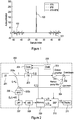
- the autocorrelations of a pair of complementary Golay codes have the property of adding to a delta function, as illustrated in Figure 1 .
- Figure 1 shows the autocorrelation of a first Golay code 101, and the autocorrelation of a second, complementary, Golay code 102. Adding the first autocorrelation 101 to the second 102 results in delta function 103. Reflections from a pair of complementary Golay code probe signals can therefore be used to approximate the reflections in response to a narrow, high power probe pulse (i.e. a delta function). This increase in power of the probe signal does not come at the expense of spatial resolution.
- Coherent OTDRs employing Golay codes may be optimal in terms of the compromise between dynamic range and spatial resolution, but existing OTDRs employing Golay codes are difficult to implement due to stringent requirements for the laser source linewidth.
- a further issue relates to amplification when performing OTDR in a system.
- Repeaters are typically provided along a fibre link, and these are unidirectional elements.
- two separate bi-directional fibre paths and a feedback between them and each of their corresponding amplifiers are necessary to monitor the link past the first repeater.
- the first fibre span the most susceptible to failure due to its proximity to the shore, cannot be monitored.
- part of the pump power will travel in the direction of the backscatter light and affect the OTDR measurements.
- US 2009/027656 discloses a system and method for time domain reflectometry (OTDR) using multi-resolution code sequences; one or more subsets of a set of predefined complementary code sequences may be transmitted as an OTDR signal to provide multi-resolution capability.
- OTDR time domain reflectometry
- a method of time domain reflectometry comprising:
- the Golay code may be a bipolar Golay code having a first and second state.
- an N-state Golay code may be used, encoded in N frequencies of light (one of the N frequencies being the first frequency).
- the method comprises repeating the steps of encoding, transmitting and detecting, and producing a first and second average detected reflection signal respectively derived from the first and second detected reflection signal.
- the data may comprise a digitised version of the average reflection signal
- Processing the data comprises the following steps:
- the step of determining the first time series of instantaneous power of the reflected signals may comprise producing first downconverted reflection signals.
- Producing the first downconverted reflection signals may comprise mixing the first average detected reflection signal with a signal having a third frequency, the third frequency being substantially equal to the difference between the second and first frequencies.
- the step of determining the second time series of instantaneous power of the reflected signal may comprise producing a second downconverted reflection signal.
- Producing the second downconverted reflection signal may comprise mixing the second average detected reflection signal with a signal having the third frequency.
- the third frequency may be selected to at least partially compensate for any changes in the frequency of the source signal during a round trip of the test signals.
- Producing the first and second downconverted reflection signals may further comprise:
- Demodulating of both the first and second average detected reflection signal may be performed by a digital signal processor.
- the method may further comprise low-pass filtering the downconverted first and second average detected reflection signals to produce demodulated first and second average detected reflection signals.
- the method may further comprise squaring each of the first and second filtered demodulated average detected reflection signals.
- the method may further comprise summing signals after the step of squaring.
- the processing step may be performed using a digital signal processor.
- the method may comprise using an electronic mixer to downconvert the first and second average detected reflection signals by mixing at least part of the first and second average detected reflection signals with an electronic local oscillator signal having a third frequency that is substantially equal to the difference between the second and first frequencies.
- the detecting step may be performed using a fully coherent detector, to detect in-phase and quadrature horizontally polarised signals, and in-phase and quadrature vertically polarised signals.
- the method may further comprise averaging the power detected by the fully coherent detector.
- the step of detecting may be performed using at least one balanced photodiode (e.g. four, in the case of a coherent detector).
- at least one balanced photodiode e.g. four, in the case of a coherent detector.
- an optical time domain reflectometer comprising:
- the detector may comprise a balanced photodiode.
- the reflectometer further comprises a low pass filter arranged to filter the first and second detected reflection signals, an analogue to digital converter, configured to receive the first and second detected reflection signals and a memory configured to store digitised first and second detected reflection signals.
- the memory may further be configured to average multiple reflection signals, and to store the average.
- the memory may store the first and second Golay codes used to encode the first and second Golay code test signals.
- the reflectometer may further comprise a controller and a clock, wherein:
- the controller may read the first and second Golay code from the memory.
- the processor may comprise a digital signal processor.
- the reflectometer may further comprise an electronic mixer configured to demodulate the second detected reflection signal by mixing the second detected reflection signal with an electronic local oscillator signal selected to have substantially the same frequency as the difference between the second and first frequencies.
- the detector may comprise a fully coherent detector, configured to detect in-phase and quadrature horizontally polarised signals, and in-phase and quadrature vertically polarised signals.
- the reflectometer may further comprise a display for displaying results derived from the processing of the data by the processor.
- the reflectometer may comprise:
- the reflectometer may further comprise at least one optical amplification stage before the downstream fibre between the frequency modulator and the re-circulator.
- the optical feedback path may comprise a filter configured to remove a Raman pump wavelength.
- the system may further comprise a Raman pump, configured to provide a Raman pump source to the downstream optical fibre so as to produce Raman amplification therein.
- a Raman pump configured to provide a Raman pump source to the downstream optical fibre so as to produce Raman amplification therein.
- Each and every feature of the first aspect may be combined with the features of each and every feature of the second aspect or third aspect.
- Each of the features of the second and third aspects are also applicable to the first aspect.
- Figure 1 shows a OTDR system comprising a reflectometer 200.
- the reflectometer 200 comprises a laser source 201, splitter/couplers 202a, 202b, frequency modulator 203, code block 204, clock 205, detector 206, low pass filter 207, analogue to digital converter 208, memory 209, digital signal processor 210; display 211; optical amplifier 301, re-circulator 302, feedback optical path 303 and combiner 304.
- the laser source 201 provides a source optical signal with a first frequency f 1 to the splitter 202a, which sends a first portion of the source optical signal to the modulator 203, and a second portion to the detector 206. It will be appreciated that the first frequency may vary slightly due to the spectral bandwidth of the laser source 201.
- the code block 204 may read the code sequence from the memory 209.
- the code sequence may comprise a Golay code.
- the first frequency f 1 may represent a +1 of a bipolar Golay code
- the second frequency f 2 may represent a -1 of the bipolar Golay code.
- the output from the modulator 203 is sent as a probe signal along one or more fibre link 300, via an output interface (e.g. an optical fibre connector).
- the code block 204 receives a clock signal from the clock 205, and modulates the probe signal with a modulation rate f b .
- the frequency modulator 203 may comprise an acoustic optic modulator (AOM) electro-optic modulator (EOM) Bragg cell or a Mach-Zehnder Interferometer (MZI).
- AOM acoustic optic modulator
- EOM electro-optic modulator
- MZI Mach-Zehnder Interferometer
- the reflectometer 200 is for coupling to a first and second fibre, respectively for carrying communication signals in a downstream and an upstream direction.
- the reflectometer 200 comprises one or more optically pumped amplifiers 301.
- Optically pumped amplifiers 301 are generally unidirectional so would prevent reflections from propagating against the flow of the signal.
- a cross coupler 303 is therefore provided between the downstream and upstream optical fibres after each amplifier 301 (or the final amplifier), so that reflections from the fibre downstream of the amplifier 301 will be coupled into the upstream fibre to return to the reflectometer 200.
- a Raman pump filter may be included in the cross coupler 303.
- Reflections from the first span of fibre under test in the downstream direction are coupled into the cross coupler 303 by re-circulator 302, and the reflected signals from the cross coupler 303 are coupled to the upstream optical fibre by coupler 304 to join reflected signals arriving at the coupler 304 from the upstream optical fibre.
- the fibre under test may include similar cross couplers after each amplification stage, so as to return reflected signals to the reflectometer 200 via the upstream fibre.
- the second portion of the source optical signal from the coupler 202a is provided to the detector 206, which also receives reflection signals via the upstream optical fibre.
- the detector 206 optically heterodynes the second portion of the source optical signal, having the first frequency f 1 , with the reflection signal, which is modulated, so includes the first frequency f 1 and the second frequency f 2 .
- the effect of the mixing at the detector 206 will produce lower sidebands in the output of the detector 206.
- the source frequency may not be perfectly stable, which may result in a frequency deviation f IF between the first frequency of the first portion of the source optical signal at the moment of transmission and the frequency of the second portion of the optical signal at the moment of reception.
- the result of optical heterodyning may therefore be a signal with frequencies of f IF and f IF +f 2 -f 1 .
- the detector 206 may be a balanced photodiode, with the first and second sides of the balanced photodiode both receiving the second portion of the source signal and the reflection signal from the upstream optical fibre (via the coupler 202b).
- the signal from the detector 206 is provided to the low pass filter 207, which provides anti-aliasing for the analogue to digital converter (ADC) 208 and removes the upper sidebands from the signal, leaving the frequency f b , corresponding with the power of the first frequency (e.g. the reflections from the +1 part of the Golay code probe signal) and the frequency (f 2 -f 1 ) (e.g. corresponding with the reflections from the -1 part of the Golay code probe signal).
- ADC analogue to digital converter
- the output from the low pass filter 207 is provided to the ADC 208, which samples the signal at a rate f s , sufficient to fully capture the frequency f 2 -f 1 (e.g. f s ⁇ 2 ⁇ f).
- the output of the ADC 208 is received by memory block 209.
- Each probe signal may produce a relatively noisy reflection signal.
- the signal to noise ratio of the detected reflections can be improved by repeating the process of sending a probe signal and receiving the reflections, and then averaging the signals that result (from the ADC).
- the clock 205 therefore provides the clock signal to both the code block 204 and the memory 209.
- the code block 204 is configured to encode the probe signal (using the frequency modulator 203), then wait for a period of time corresponding with the expected round trip time for the probe signal (and reflection from the end of the fibre link 300), then repeat the probe signal.
- the memory block 209 Since the memory block 209 receives the same clock signal as the code block 204, the memory block 209 can synchronise its operation with the probe signal transmission, and average the reflection signals corresponding with each time of flight (i.e. location in the fibre link 300). This averaging may be done as the signals are repeated, so as to avoid the need for storing the reflection signal from each cycle of the averaging process.
- a first Golay code probe may be followed by a second complementary Golay code probe. This cycle may be repeated to build up an average signal in the memory. Alternatively, a number of first Golay code probe signal reflections may be averaged, and then a number of second Golay code probe signal reflections may be averaged.
- an average reflection signal for the first and second Golay code probe signals will be stored in the memory 209. These average signals are further processed by the digital signal processor (DSP) to approximate the reflections from the fibre link 300 in response to an impulse (delta function) probe signal.
- DSP digital signal processor
- the reflection return power in response to a delta function may be plotted or otherwise displayed on the optional display 211. Alternatively, the results may be transmitted for display or further processing elsewhere.
- FIG. 3 An example DSP configuration is shown in Figure 3 .
- the upper leg of the DSP block diagram receives the averaged signal r A (t) from the memory, corresponding with the reflections from the first Golay code, and the lower leg of the DSP block diagram receives the averaged signal r B (t), corresponding with the reflections from the second Golay code.
- Both the upper and lower legs process the averaged signals in the same way, up to the convolution block 291.
- the averaged signal r A (t) is mixed (at mixer 251) with a generated local signal at an intermediate frequency f IF which compensates for any drift in the first frequency of the laser source 201 (e.g. between the time of transmission and detection), leaving a signal spectrum centred at DC (direct current), that corresponds with a time history of the power of the first frequency f 1 in the reflections.
- the DSP 210 may determine an appropriate frequency f IF , for instance by searching for the maximum of a function calculated from the spectral distribution of the averaged signal r A (t).
- the averaged signal r A (t) is also mixed (at mixer 261) with a signal having a frequency of (f IF + ⁇ f), where ⁇ f is (f 2 -f 1 ). This demodulates the reflection signals from the second frequency f 2 .
- the output from the mixer 251 is provided to squaring and summing blocks 253, 254 which results in a time history of the instantaneous average power of the reflections of the first frequency f 1 . Squaring of the data means that any phase information is discarded, which means that the stringent laser source linewidth requirements can be relaxed.
- the output from the summation block 264 is similarly a time history of the instantaneous average power of the reflections of the second frequency f 2 . Combining these two signals together at the summation block 290a, and giving the second frequency f 2 a negative sign results in the reflected bipolar Golay code (i.e. reflected signals from f 1 and reflected signals from f 2 are complementary).
- the lower leg of the DSP operates in a similar way on the reflections r B (t) from the second Golay code.
- An autocorrelation operation is equivalent to convolving the output x A (t), x B (t) from the summation blocks 290a, 290b with the corresponding time inverted Golay codes A(-t) and B(-t), as shown on blocks 291a and 291b respectively.
- the autocorrelation of the reflections from the first and second Golay codes are added at block 292, which results in an approximation of the reflections h(t) from an impulse (delta function) probe signal.
- the subsequent chain of low pass filter 207, ADC 208, memory 209 and DSP 210 function in substantially the same way as the embodiment of Figures 2 and 3 , except that the DSP stage 210 no longer needs to downmix the frequency ⁇ f (although a DSP mixing stage may still be retained to compensate for frequency instability in the output of the source 201).
- Figure 5 shows a further alternative embodiment, in which a full coherent receiver is used to detect both horizontally polarised signals X and vertically polarised signals Y in both in-phase I and quadrature Q.
- Each of these four detection channels may be low pass filtered in filter stage 207, and then converted to a digital signal at a subsequent ADC stage 208.
- a power averaging block 215 is provided to average the instantaneous power for the reflections detected by each channel of the coherent detector 214. In some embodiments this power averaging may be performed in the memory block stage 209.
- the memory 209 stores and averages the average output from the detector channels over the number of cycles that the code is transmitted.
- the DSP 210 receives the average power stored by the memory, and operates in a similar way as described with reference to Figure 3 .
- the full return power of the probe signal can be measured, such that a further 6dB improvement in dynamic range (or alternatively, a 3dB improvement in the SWDR) is obtained.
- the use of complementary Golay codes mean that a substantially constant average power is maintained across any optical amplifiers in the fibre link under test, so that they will continue to operate in a saturation mode for the duration of fibre characterisation (which removes any need for gain control of these amplifiers during test).
- the source 201 is maintained in continuous wave operation, at a power equal to the average power of the launched modulated codes, to further maintain the constant gain of the amplifiers.
- Monitoring (or measurement) of the first fibre span is enabled by the provision of a feedback path between the input and output fibres (i.e. the cross coupler 303 in each of Figures 2 , 4 and 5 ).
- a Raman pump filter in this cross coupling pathway avoids the backscatter measurements being affected by Raman pump light.
- Figure 6 shows simulated results from a reflectometer according to the embodiment of Figure 2 .
- a 50km single-span SSMF standard single mode fibre
- the results in Figure 6 compare Golay codes of 8 bits (403) 32 bits (402), and 128 bits (401).
- Figure 7 illustrates the spatial resolution at the reflection at 20km.
- FIG. 8 A multi-span characterisation is demonstrated in Figure 8 , in which results from a 128 bit Golay code (411), 32 bit Golay code (412) and 8 bit Golay code (413) are illustrated.
- the pulse width was 1 ⁇ s.
- Embodiments of the present invention may provide a number of advantages over prior art reflectometers.
- a reduced number of frequencies may be required for the probe signals, reducing the complexity of the frequency modulation arrangement. Transitions between frequencies complementary code values (e.g.f 1 and f 2 , corresponding with +1 and -1) may be more rapid, without the need to transition through an intermediate frequency.
- a single frequency modulator e.g. providing only a fixed single shift in frequency
- Optical heterodyning may be simplified: a single unmodulated frequency may be mixed with the returning reflections to downconvert the signals (e.g. suitable for ADC and subsequent DSP processing).
- a single detector may be used to detect the reflected signals.
- Embodiments of the invention may be insensitive to polarisation scrambling of the reflected signals.
Landscapes
- Physics & Mathematics (AREA)
- Chemical & Material Sciences (AREA)
- Analytical Chemistry (AREA)
- General Physics & Mathematics (AREA)
- Optics & Photonics (AREA)
- Electromagnetism (AREA)
- Engineering & Computer Science (AREA)
- Computer Networks & Wireless Communication (AREA)
- Signal Processing (AREA)
- Optical Communication System (AREA)
Description
- The present invention relates to an apparatus and method for performing optical time domain reflectometry.
- Optical time domain reflectometry (OTDR) is used to characterise an optical fibre, or an optical communications link (e.g. including multiple fibre spans and amplification stages). A series of optical pulses are transmitted into the fibre. The pulses are scattered or reflected from points along the link/fibre. The time delay between transmission of the pulses and receipt of a reflection indicates the distance of the reflecting location in the fibre/link. The strength of the return pulses as a function of time from the transmitted pulse can therefore be used to infer characteristics of the fibre. The round-trip time for the test pulse and reflection can be converted into a distance from the OTDR instrument. The performance of an OTDR instrument is typically characterised by the accuracy of a loss measurement, and by the trade-off between spatial resolution and dynamic range.
- Long-distance undersea fibre communications links typically comprise multiple fibre spans, linked by optical amplification stages. Such links require characterisation, fault detection and localisation, for the purpose of performance monitoring and also to enable remedial action in the event of a fault.
- There is typically a trade-off between the spatial resolution and dynamic range of an OTDR measurement. There is generally a limit to the laser power that can be used in a test pulse, and the detector has a minimum detectable reflected signal. A longer duration pulse can be used to increase the energy of the reflections, but this will come at the expense of spatial resolution - a longer duration pulse will not provide the spatial resolution that a shorter duration pulse would.
- One approach for improving the trade-off between dynamic range and spatial resolution is to employ Golay codes as probe signals. The autocorrelations of a pair of complementary Golay codes have the property of adding to a delta function, as illustrated in
Figure 1 . -
Figure 1 shows the autocorrelation of a first Golaycode 101, and the autocorrelation of a second, complementary, Golaycode 102. Adding thefirst autocorrelation 101 to the second 102 results indelta function 103. Reflections from a pair of complementary Golay code probe signals can therefore be used to approximate the reflections in response to a narrow, high power probe pulse (i.e. a delta function). This increase in power of the probe signal does not come at the expense of spatial resolution. - When coherent detection is employed with Golay codes, very narrow linewidth laser sources are necessary as the phase across the code needs to be maintained during the entire roundtrip time. As typical long-haul optical transmission distances are equivalent to roundtrip times of the order of 10-100 ms, phase coherence across the probe pulses is difficult to achieve in practice. One way to avoid these requirements is to resort to intensity modulation/direct detection (IM/DD), in which the two Golay code pairs (which are inherently bipolar), are split into four unipolar sequences and transmitted by amplitude modulation (as discussed in
US5000568 and M. Nazarathy, et. al., "Real-time long range complementary correlation optical time domain reflectometry", Journal of Lightwave Technology, Vol. 7, No. 1, pp. 24-38, January 1989). This allows wider linewidth sources to be employed and measurements to be made that are independent of phase and polarisation fluctuations, but doubles the measurement time.US6046797 discloses using alternating the probe frequency between three different values to transmit a Golay code. - Coherent OTDRs employing Golay codes may be optimal in terms of the compromise between dynamic range and spatial resolution, but existing OTDRs employing Golay codes are difficult to implement due to stringent requirements for the laser source linewidth.
- A further issue relates to amplification when performing OTDR in a system. Repeaters are typically provided along a fibre link, and these are unidirectional elements. Conventionally, two separate bi-directional fibre paths and a feedback between them and each of their corresponding amplifiers are necessary to monitor the link past the first repeater. In this setup, the first fibre span, the most susceptible to failure due to its proximity to the shore, cannot be monitored. Moreover, when the repeater technology is based on Raman amplification, part of the pump power will travel in the direction of the backscatter light and affect the OTDR measurements.
- An improved apparatus and method for OTDR is desired.
-
US 2009/027656 discloses a system and method for time domain reflectometry (OTDR) using multi-resolution code sequences; one or more subsets of a set of predefined complementary code sequences may be transmitted as an OTDR signal to provide multi-resolution capability. - According to a zeroth aspect of the present invention, there is provided a method according to claim 1 and an optical time domain reflectometer according to claim 9. Optional features of the method and the reflectometer are set out in the dependent claims.
- According to a first aspect of the invention, there is provided: a method of time domain reflectometry, comprising:
- providing a source optical signal having a first frequency;
- encoding and transmitting a first Golay code test signal and then a second complementary Golay code test signal along an optical fibre, wherein encoding the first and second Golay code test signals comprises using a frequency modulator on a first portion of the source optical signal such that one of the states of the Golay code is encoded as the first frequency, and another state of the Golay code is encoded as a second frequency, the second frequency being produced by shifting the frequency of the optical signal from the first frequency to the second frequency;
- detecting reflections of the first and second Golay code test signals that are mixed with a second portion of the source optical signal at a heterodyne detector to produce a first and second detected reflection signal, respectively corresponding with reflections of the first and second Golay code test signals;
- processing data derived from the first and second detected reflection signal to approximate reflections from the optical fibre in response to a delta function test signal.
- The Golay code may be a bipolar Golay code having a first and second state. In other embodiments, an N-state Golay code may be used, encoded in N frequencies of light (one of the N frequencies being the first frequency).
- The method comprises repeating the steps of encoding, transmitting and detecting, and producing a first and second average detected reflection signal respectively derived from the first and second detected reflection signal. The data may comprise a digitised version of the average reflection signal
- Processing the data comprises the following steps:
- for each of the first and second average detected reflection signals:
- i) determining a first time series of instantaneous power of the reflected signal frequency corresponding with the first frequency of the test signal;
- ii) determining a second time series of instantaneous power of the reflected signal frequency corresponding with the second frequency of the test signal; and
- iii) subtracting the second time series of instantaneous power from the first time series of instantaneous power to produce a time series of instantaneous power corresponding to a bipolar code;
- correlating the bipolar code time series for the first average detected reflection signal with the first Golay code test signal to produce a first correlated signal;
- correlating the bipolar code time series for the second average detected reflection signal with the second Golay code test signal to produce a second correlated signal; and
- adding the first and second correlated signals so as to approximate reflections from the optical fibre in response to a delta function test signal.
- The step of determining the first time series of instantaneous power of the reflected signals may comprise producing first downconverted reflection signals. Producing the first downconverted reflection signals may comprise mixing the first average detected reflection signal with a signal having a third frequency, the third frequency being substantially equal to the difference between the second and first frequencies. The step of determining the second time series of instantaneous power of the reflected signal may comprise producing a second downconverted reflection signal. Producing the second downconverted reflection signal may comprise mixing the second average detected reflection signal with a signal having the third frequency.
- The third frequency may be selected to at least partially compensate for any changes in the frequency of the source signal during a round trip of the test signals.
- Producing the first and second downconverted reflection signals may further comprise:
- mixing the first average detected reflection signal with a signal having a fourth frequency, the fourth frequency selected to at least partially compensate for any changes in the frequency of the source signal during a round trip of the test signals; and
- mixing the second average detected reflection signal with a signal having the fourth frequency.
- Demodulating of both the first and second average detected reflection signal may be performed by a digital signal processor.
- The method may further comprise low-pass filtering the downconverted first and second average detected reflection signals to produce demodulated first and second average detected reflection signals.
- The method may further comprise squaring each of the first and second filtered demodulated average detected reflection signals. The method may further comprise summing signals after the step of squaring.
- The processing step (or processing steps) may be performed using a digital signal processor.
- The method may comprise using an electronic mixer to downconvert the first and second average detected reflection signals by mixing at least part of the first and second average detected reflection signals with an electronic local oscillator signal having a third frequency that is substantially equal to the difference between the second and first frequencies.
- The detecting step may be performed using a fully coherent detector, to detect in-phase and quadrature horizontally polarised signals, and in-phase and quadrature vertically polarised signals.
- The method may further comprise averaging the power detected by the fully coherent detector.
- The step of detecting may be performed using at least one balanced photodiode (e.g. four, in the case of a coherent detector).
- According to a second aspect, there is provided an optical time domain reflectometer, comprising:
- a laser source, operable to output a source optical signal having a first frequency;
- a frequency modulator arranged to receive a first portion of the source optical signal and configured to encode the first portion of the source optical signal with a a first Golay code test signal and a second complementary Golay code test signal, such that one of the states of the Golay codes is encoded as the first frequency, and another state of the Golay codes is encoded as a second frequency, the second frequency being produced by shifting the frequency of the optical signal from the first frequency to the second frequency;:
- an output interface for transmitting the first and second Golay code test signals along an optical fibre;
- an input interface for receiving reflections of the first and second Golay code from the optical fibre;
- a detector configured to receive a second portion of the source optical signal and the reflections from the input interface so as to heterodyne the reflections with the second portion of the source optical signal and produce a first and second detected reflection signal, respectively corresponding with the first and second Golay code test signals;
- a processor configured to process data derived from the first and second detected reflection signal to approximate reflections from the optical fibre in response to a delta function test signal.
- The detector may comprise a balanced photodiode.
- The reflectometer further comprises a low pass filter arranged to filter the first and second detected reflection signals, an analogue to digital converter, configured to receive the first and second detected reflection signals and a memory configured to store digitised first and second detected reflection signals. The memory may further be configured to average multiple reflection signals, and to store the average. The memory may store the first and second Golay codes used to encode the first and second Golay code test signals.
- The reflectometer may further comprise a controller and a clock, wherein:
- the controller is configured to provide a common clock signal to the memory and the frequency modulator, and to cause the frequency modulator to repeatedly transmit the first and second Golay code test signals; and
- the memory is configured to use timing information from the clock to store an average of the reflections from the first and second Golay code test signals.
- The controller may read the first and second Golay code from the memory.
- The processor may comprise a digital signal processor.
- The reflectometer may further comprise an electronic mixer configured to demodulate the second detected reflection signal by mixing the second detected reflection signal with an electronic local oscillator signal selected to have substantially the same frequency as the difference between the second and first frequencies.
- The detector may comprise a fully coherent detector, configured to detect in-phase and quadrature horizontally polarised signals, and in-phase and quadrature vertically polarised signals.
- The reflectometer may further comprise a display for displaying results derived from the processing of the data by the processor.
- The reflectometer may comprise:
- a downstream optical fibre for transmitting signals in a first direction, and an upstream optical fibre for transmitting signals in a second, opposite, direction;
- an optical feedback path and a re-circulator, connecting a distal portion of the downstream optical fibre to a distal portion of the upstream optical fibre; and
- wherein the output interface comprises the downstream optical fibre, and the input interface comprises the upstream optical fibre.
- The reflectometer may further comprise at least one optical amplification stage before the downstream fibre between the frequency modulator and the re-circulator.
- The optical feedback path may comprise a filter configured to remove a Raman pump wavelength.
- The system may further comprise a Raman pump, configured to provide a Raman pump source to the downstream optical fibre so as to produce Raman amplification therein.
- Each and every feature of the first aspect may be combined with the features of each and every feature of the second aspect or third aspect. Each of the features of the second and third aspects are also applicable to the first aspect.
- Embodiments of the invention will now be described, purely by way of example, with reference to the accompanying drawings, in which:
-
Figure 1 is a graph illustrating the autocorrelation summation of complementary Golay codes; -
Figure 2 is a block diagram of an OTDR system according to a first embodiment; -
Figure 3 is a block diagram of the DSP of the first embodiment; -
Figure 4 is a block diagram of an OTDR system according to a second embodiment, in which an electrical mixer is employed for demodulating one of the frequencies; -
Figure 5 is a block diagram of an OTDR system according to a third embodiment, in which a full coherent receiver is used to detect the reflected signals; -
Figure 6 is a graph showing simulation results of measurement of a 50km standard single mode fibre, with a lumped loss of 1dB from 20km and two 15dB reflections at 20km within the fibre and at the end of the fibre span; -
Figure 7 is a graph showing the data displayed onFigure 6 , showing the detail of the reflection at 20km; and -
Figure 8 is a graph showing simulation results of measurement of five 50km standard single mode fibre spans, with a lumped loss of 1dB from 20km and a 15dB reflection at 20km within the fibre and at the end of the last fibre span. -
Figure 1 shows a OTDR system comprising areflectometer 200. Thereflectometer 200 comprises alaser source 201, splitter/couplers frequency modulator 203,code block 204,clock 205,detector 206,low pass filter 207, analogue todigital converter 208,memory 209,digital signal processor 210;display 211;optical amplifier 301, re-circulator 302, feedbackoptical path 303 andcombiner 304. - The
laser source 201 provides a source optical signal with a first frequency f1 to thesplitter 202a, which sends a first portion of the source optical signal to themodulator 203, and a second portion to thedetector 206. It will be appreciated that the first frequency may vary slightly due to the spectral bandwidth of thelaser source 201. - The
modulator 203 is configured to modulate the frequency of the first portion of the source optical signal between the first frequency f1 and a second frequency f2 (with f2-f1=Δf), in accordance with a code sequence provided by thecode block 204. Thecode block 204 may read the code sequence from thememory 209. The code sequence may comprise a Golay code. In the resulting binary frequency shift key (BFSK) modulated signal the first frequency f1 may represent a +1 of a bipolar Golay code, and the second frequency f2 may represent a -1 of the bipolar Golay code. The output from themodulator 203 is sent as a probe signal along one ormore fibre link 300, via an output interface (e.g. an optical fibre connector). Thecode block 204 receives a clock signal from theclock 205, and modulates the probe signal with a modulation rate fb. The inverse of the modulation rate is the pulse width τ=1/fb, which determines the spatial resolution of the measurement. As the code propagates, reflections of the partial code during the time t≤t0+L·τ·r·vg/2 is measured and the full code during the time t0+L·τ·vg/2 < t ≤ tr, where t0 is the time when the probe signal leaves the reflectometer, L is the code length, D is the total round trip distance for the fibre being interrogated, tr=t0+2·D/vg is the roundtrip time of the fibre and vg the speed of light in the fibre core. - The
frequency modulator 203 may comprise an acoustic optic modulator (AOM) electro-optic modulator (EOM) Bragg cell or a Mach-Zehnder Interferometer (MZI). - The
reflectometer 200 is for coupling to a first and second fibre, respectively for carrying communication signals in a downstream and an upstream direction. - The
reflectometer 200 comprises one or more optically pumpedamplifiers 301. Optically pumpedamplifiers 301 are generally unidirectional so would prevent reflections from propagating against the flow of the signal. Across coupler 303 is therefore provided between the downstream and upstream optical fibres after each amplifier 301 (or the final amplifier), so that reflections from the fibre downstream of theamplifier 301 will be coupled into the upstream fibre to return to thereflectometer 200. In order to avoid Raman pump signals (used for Raman amplification) from interfering with the measurement, a Raman pump filter may be included in thecross coupler 303. Reflections from the first span of fibre under test in the downstream direction are coupled into thecross coupler 303 byre-circulator 302, and the reflected signals from thecross coupler 303 are coupled to the upstream optical fibre bycoupler 304 to join reflected signals arriving at thecoupler 304 from the upstream optical fibre. The fibre under test may include similar cross couplers after each amplification stage, so as to return reflected signals to thereflectometer 200 via the upstream fibre. - The second portion of the source optical signal from the
coupler 202a is provided to thedetector 206, which also receives reflection signals via the upstream optical fibre. Thedetector 206 optically heterodynes the second portion of the source optical signal, having the first frequency f1, with the reflection signal, which is modulated, so includes the first frequency f1 and the second frequency f2. The effect of the mixing at thedetector 206 will produce lower sidebands in the output of thedetector 206. The source frequency may not be perfectly stable, which may result in a frequency deviation fIF between the first frequency of the first portion of the source optical signal at the moment of transmission and the frequency of the second portion of the optical signal at the moment of reception. The result of optical heterodyning may therefore be a signal with frequencies of fIF and fIF+f2-f1. - The
detector 206 may be a balanced photodiode, with the first and second sides of the balanced photodiode both receiving the second portion of the source signal and the reflection signal from the upstream optical fibre (via thecoupler 202b). - The signal from the
detector 206 is provided to thelow pass filter 207, which provides anti-aliasing for the analogue to digital converter (ADC) 208 and removes the upper sidebands from the signal, leaving the frequency fb, corresponding with the power of the first frequency (e.g. the reflections from the +1 part of the Golay code probe signal) and the frequency (f2-f1) (e.g. corresponding with the reflections from the -1 part of the Golay code probe signal). - The output from the
low pass filter 207 is provided to theADC 208, which samples the signal at a rate fs, sufficient to fully capture the frequency f2-f1 (e.g. fs≥ 2Δf). The output of theADC 208 is received bymemory block 209. - Each probe signal may produce a relatively noisy reflection signal. The signal to noise ratio of the detected reflections can be improved by repeating the process of sending a probe signal and receiving the reflections, and then averaging the signals that result (from the ADC). The
clock 205 therefore provides the clock signal to both thecode block 204 and thememory 209. Thecode block 204 is configured to encode the probe signal (using the frequency modulator 203), then wait for a period of time corresponding with the expected round trip time for the probe signal (and reflection from the end of the fibre link 300), then repeat the probe signal. - Since the
memory block 209 receives the same clock signal as thecode block 204, thememory block 209 can synchronise its operation with the probe signal transmission, and average the reflection signals corresponding with each time of flight (i.e. location in the fibre link 300). This averaging may be done as the signals are repeated, so as to avoid the need for storing the reflection signal from each cycle of the averaging process. - In some embodiments, a first Golay code probe may be followed by a second complementary Golay code probe. This cycle may be repeated to build up an average signal in the memory. Alternatively, a number of first Golay code probe signal reflections may be averaged, and then a number of second Golay code probe signal reflections may be averaged.
- Once a suitable number of averaging cycles (e.g. at least 100, 500, 1000 or 10000) are completed, an average reflection signal for the first and second Golay code probe signals will be stored in the
memory 209. These average signals are further processed by the digital signal processor (DSP) to approximate the reflections from thefibre link 300 in response to an impulse (delta function) probe signal. - The reflection return power in response to a delta function may be plotted or otherwise displayed on the
optional display 211. Alternatively, the results may be transmitted for display or further processing elsewhere. - An example DSP configuration is shown in
Figure 3 . The upper leg of the DSP block diagram receives the averaged signal rA(t) from the memory, corresponding with the reflections from the first Golay code, and the lower leg of the DSP block diagram receives the averaged signal rB(t), corresponding with the reflections from the second Golay code. Both the upper and lower legs process the averaged signals in the same way, up to the convolution block 291. - Considering the upper leg, the averaged signal rA(t) is mixed (at mixer 251) with a generated local signal at an intermediate frequency fIF which compensates for any drift in the first frequency of the laser source 201 (e.g. between the time of transmission and detection), leaving a signal spectrum centred at DC (direct current), that corresponds with a time history of the power of the first frequency f1 in the reflections. The
DSP 210 may determine an appropriate frequency fIF, for instance by searching for the maximum of a function calculated from the spectral distribution of the averaged signal rA(t). - The averaged signal rA(t) is also mixed (at mixer 261) with a signal having a frequency of (fIF+Δf), where Δf is (f2-f1). This demodulates the reflection signals from the second frequency f2. The output from the
mixer 251 is provided to squaring and summingblocks - The output from the summation block 264 is similarly a time history of the instantaneous average power of the reflections of the second frequency f2. Combining these two signals together at the
summation block 290a, and giving the second frequency f2 a negative sign results in the reflected bipolar Golay code (i.e. reflected signals from f1 and reflected signals from f2 are complementary). - The lower leg of the DSP operates in a similar way on the reflections rB(t) from the second Golay code.
- In order to approximate the reflections in response to a delta function, it is necessary to add the autocorrelations of the reflections from the complementary Golay codes. An autocorrelation operation is equivalent to convolving the output xA(t), xB(t) from the summation blocks 290a, 290b with the corresponding time inverted Golay codes A(-t) and B(-t), as shown on
blocks block 292, which results in an approximation of the reflections h(t) from an impulse (delta function) probe signal. -
Figure 4 shows an alternative embodiment with similar features to the embodiment ofFigure 2 , except that an analogueelectrical mixer 212 is used to demodulate the second frequency f2, by mixing the output from thedetector 206 with a signal from a localelectrical oscillator 213 having frequency Δf (Δf=f2-f1). This means that theADC 208 does not need to sample as quickly, potentially simplifying theADC 208 and reducing the cost of theinstrument 200. - The subsequent chain of
low pass filter 207,ADC 208,memory 209 andDSP 210 function in substantially the same way as the embodiment ofFigures 2 and3 , except that theDSP stage 210 no longer needs to downmix the frequency Δf (although a DSP mixing stage may still be retained to compensate for frequency instability in the output of the source 201). -
Figure 5 shows a further alternative embodiment, in which a full coherent receiver is used to detect both horizontally polarised signals X and vertically polarised signals Y in both in-phase I and quadrature Q. Each of these four detection channels may be low pass filtered infilter stage 207, and then converted to a digital signal at asubsequent ADC stage 208. Apower averaging block 215 is provided to average the instantaneous power for the reflections detected by each channel of thecoherent detector 214. In some embodiments this power averaging may be performed in thememory block stage 209. - The
memory 209 stores and averages the average output from the detector channels over the number of cycles that the code is transmitted. TheDSP 210 receives the average power stored by the memory, and operates in a similar way as described with reference toFigure 3 . - In this embodiment, regardless of the polarisation scrambling of the backscattered light, the full return power of the probe signal can be measured, such that a further 6dB improvement in dynamic range (or alternatively, a 3dB improvement in the SWDR) is obtained.
- In all embodiments, the use of complementary Golay codes mean that a substantially constant average power is maintained across any optical amplifiers in the fibre link under test, so that they will continue to operate in a saturation mode for the duration of fibre characterisation (which removes any need for gain control of these amplifiers during test). At the end of the modulation period, the
source 201 is maintained in continuous wave operation, at a power equal to the average power of the launched modulated codes, to further maintain the constant gain of the amplifiers. - Monitoring (or measurement) of the first fibre span is enabled by the provision of a feedback path between the input and output fibres (i.e. the
cross coupler 303 in each ofFigures 2 ,4 and5 ). The use of a Raman pump filter in this cross coupling pathway avoids the backscatter measurements being affected by Raman pump light. -
Figure 6 shows simulated results from a reflectometer according to the embodiment ofFigure 2 . A 50km single-span SSMF (standard single mode fibre) is characterised, including measuring the attenuation coefficient of 0.2 dB/km, detecting lumped losses and localised reflection points. A 1dB lumped loss at 20km, and two 15db reflections one at 20km and the other at the end of the link were simulated. The results inFigure 6 compare Golay codes of 8 bits (403) 32 bits (402), and 128 bits (401).Figure 7 illustrates the spatial resolution at the reflection at 20km. - By employing 1µs pulses, a 200m spatial resolution is possible: twice the resolution obtainable with conventional C-OTDR. This doubling in resolution is due to the full-width of the autocorrelation function. A 1.5dB improvement in the SWDR (single-way dynamic range) with every 4-fold increase in Golay code length , as well as a ∼2.6dB improvement in SWDR compared to the sequential IM/DD approach of the prior art are demonstrated.
- A multi-span characterisation is demonstrated in
Figure 8 , in which results from a 128 bit Golay code (411), 32 bit Golay code (412) and 8 bit Golay code (413) are illustrated. There are five 50km SSMF fibre spans, with a lumped 1dB loss at 20km and a 15dB reflection at 20km and at the end of the last fibre span. The pulse width was 1µs. - Embodiments of the present invention may provide a number of advantages over prior art reflectometers. A reduced number of frequencies may be required for the probe signals, reducing the complexity of the frequency modulation arrangement. Transitions between frequencies complementary code values (e.g.f1 and f2, corresponding with +1 and -1) may be more rapid, without the need to transition through an intermediate frequency. A single frequency modulator (e.g. providing only a fixed single shift in frequency) can be used in some embodiments. Optical heterodyning may be simplified: a single unmodulated frequency may be mixed with the returning reflections to downconvert the signals (e.g. suitable for ADC and subsequent DSP processing). In some embodiments a single detector may be used to detect the reflected signals. Embodiments of the invention may be insensitive to polarisation scrambling of the reflected signals.
- Although a number of examples have been described these are not intended to be limiting. A number of other variations are possible, within the scope of the invention, which is limited only by the appended claims.
Claims (15)
- A method of time domain reflectometry for inferring characteristics of an optical fibre, comprising:providing a source optical signal having a first frequency (f1);encoding and transmitting a first Golay code test signal and then a second complementary Golay code test signal along the optical fibre, the first Golay code test signal and the second complementary Golay code test signal each comprising multiple states, wherein encoding the first and second Golay code test signals comprises using a frequency modulator (203) on a first portion of the source optical signal such that one of the states of the Golay code is encoded as the first frequency (f1), and another state of the Golay code is encoded as a second frequency (f2), the second frequency (f2) being produced by shifting the frequency of the optical signal from the first frequency (f1) to the second frequency (f2);detecting reflections of the first and second Golay code test signals that are mixed with a second portion of the source optical signal at a heterodyne detector (206) to produce a first and second detected reflection signal, respectively corresponding with reflections of the first and second Golay code test signals;characterised in repeating the steps of encoding, transmitting and detecting, and producing a first and second average detected reflection signal respectively derived from the first and second detected reflection signal;processing data derived from the first and second detected reflection signal to approximate reflections from the optical fibre in response to a delta function test signal, wherein processing the data comprises the following steps:for each of the first and second average detected reflection signals:i) determining a first time series of instantaneous power of the reflected signal frequency corresponding with the first frequency of the test signal;ii) determining a second time series of instantaneous power of the reflected signal frequency corresponding with the second frequency of the test signal; andiii) subtracting the second time series of instantaneous power from the first time series of instantaneous power to produce a time series of instantaneous power corresponding to a bipolar code;correlating the bipolar code time series for the first average detected reflection signal with the first Golay code test signal to produce a first correlated signal;correlating the bipolar code time series for the second average detected reflection signal with the second Golay code test signal to produce a second correlated signal; andadding the first and second correlated signals so as to approximate reflections from the optical fibre in response to a delta function test signal.
- The method of claim 1, wherein the Golay code is a bipolar Golay code having a first and second state.
- The method of claim 1 or 2, wherein:the step of determining the first time series of instantaneous power of the reflected signal comprises producing a first downconverted reflection signal, wherein producing the first downconverted reflection signals comprises mixing the first average detected reflection signal with a signal having a third frequency (Δf), the third frequency (Δf) being substantially equal to the difference between the second and first frequencies; andthe step of determining the second time series of instantaneous power of the reflected signal comprises producing a second downconverted reflection signal, wherein producing the second downconverted reflection signals comprises mixing the second average detected reflection signal with a signal having the third frequency (Δf).
- The method of claim 3, wherein producing the first and second downconverted reflection signals further comprises:mixing the first average detected reflection signal with a signal having a fourth frequency, the fourth frequency selected to at least partially compensate for any changes in the frequency of the source signal during a round trip of the test signals; andmixing the second average detected reflection signal with a signal having the fourth frequency, and optionally wherein the third frequency is selected to compensate for any changes in the frequency of the source signal during a round trip of the test signals and reflections.
- The method of claim 4, wherein the downcoverting of both the first and second average detected reflection signal is performed by a digital signal processor (210).
- The method of any of claims 4 or 5, further comprising low-pass filtering the downconverted first and second average detected reflection signals to produce demodulated average detected reflection signals, and optionally further comprising squaring each of the first and second filtered demodulated average detected reflection signals.
- The method of any preceding claim, wherein the processing step is performed using a digital signal processor (210).
- The method of any preceding claim, comprising using an electronic mixer to downconvert the first and second average detected reflection signals by mixing at last part of the first and second average detected reflection signal with an electronic local oscillator signal having a third frequency that is substantially equal to the difference between the second and first frequencies; and/or
wherein the detecting step is performed using a fully coherent detector (214), to detect in-phase and quadrature horizontally polarised signals, and in-phase and quadrature vertically polarised signals, and optionally further comprising averaging the power detected by the fully coherent detector (214); and/or
wherein the step of detecting is performed using at least one balanced photodiode. - An optical time domain reflectometer (200) for inferring characteristics of an optical fibre, comprising:a laser source (201), operable to output a source optical signal having a first frequency (f1);a frequency modulator (203) arranged to receive a first portion of the source optical signal and configured to encode the first portion of the source optical signal with a first Golay code test signal and a second complementary Golay code test signal, the first Golay code test signal and the second complementary Golay code test signal each comprising multiple states, wherein the frequency modulator is configured to encode the first portion of the source optical signal with the first Golay code test signal and the second complementary Golay code test signal such that one of the states of the Golay codes is encoded as the first frequency (f1), and another state of the Golay codes is encoded as a second frequency (f2), the second frequency (f2) being produced by shifting the frequency of the optical signal from the first frequency (f1) to the second frequency (f2);an output interface for transmitting the first and second Golay code test signals along the optical fibre;an input interface for receiving reflections of the first and second Golay code from the optical fibre;a detector (206, 214) configured to receive a second portion of the source optical signal and the reflections from the input interface so as to heterodyne the reflections with the second portion of the source optical signal and produce a first and second detected reflection signal, respectively corresponding with the first and second Golay code test signals;a low pass filter (207) arranged to filter the first and second detected reflection signals;an analogue to digital converter (208), configured to receive the first and second detected reflection signals;a memory (209) configured to store digitised first and second detected reflection signals;a controller and a clock (205), characterised in thatthe controller is configured to provide a common clock signal to the memory (209) and the frequency modulator (203), and to cause the frequency modulator (203) to repeatedly transmit the first and second Golay code test signals;the memory (209) is configured to use timing information from the clock (205) to store an average of the reflections from the first and second Golay code test signals; anda processor (210) configured to process data derived from the first and second detected reflection signal to approximate reflections from the optical fibre in response to a delta function test signal;wherein the reflectometer (200) is configured to perform the method of any of claims 1 to 8.
- The reflectometer (200) of claim 9, wherein the detector (206, 214) comprises a balanced photodiode.
- The reflectometer (200) of any of claims 9 or 10, wherein the processor (210) comprises a digital signal processor; and/or
further comprising an electronic mixer configured to demodulate the second detected reflection signal by mixing the second detected reflection signal with an electronic local oscillator signal selected to have substantially the same frequency as the difference between the second and first frequencies; and/or
wherein the detector comprises a fully coherent detector (214), configured to detect in-phase and quadrature horizontally polarised signals, and in-phase and quadrature vertically polarised signals; and/or
further comprising a display (211) for displaying results derived from the processing of the data by the processor (210). - The reflectometer (200) of any preceding claim, further comprising:a downstream optical fibre for transmitting signals in a first direction, and an upstream optical fibre for transmitting signals in a second, opposite, direction;an optical feedback path (303) and a re-circulator (302), connecting a portion of the downstream optical fibre to a portion of the upstream optical fibre;wherein the output interface comprises the downstream optical fibre, and the input interface comprises the upstream optical fibre; andoptionally further comprising at least one optical amplification stage (301) coupled to the downstream fibre between the frequency modulator (203) and the re-circulator (302).
- The reflectometer (200) of claim 12, wherein the optical feedback path (302) comprises a filter configured to remove a Raman pump wavelength.
- An optical system comprising an optical fibre link and the reflectometer (200) of any of claims 9 to 11, wherein:the optical fibre link comprises a first span of downstream optical fibre and a first span of upstream optical fibre;the output interface of the reflectometer (200) is connected to the first span of downstream optical fibre, and the input interface of the reflectometer is connected to the first span of upstream optical fibre.
- The system of claim 14, further comprising at least one further span of downstream and upstream optical fibre and at least one optical amplifier disposed between each span; and optionally wherein the at least one optical amplifier (301) comprises a Raman pump, configured to provide a Raman pump source to at least one of the fibres of at least one optical span, so as to produce Raman amplification therein.
Applications Claiming Priority (2)
| Application Number | Priority Date | Filing Date | Title |
|---|---|---|---|
| GB1602313.7A GB2544125A (en) | 2016-02-09 | 2016-02-09 | Optical time domain reflectometry |
| PCT/GB2017/050285 WO2017137729A1 (en) | 2016-02-09 | 2017-02-06 | Optical time domain reflectometry |
Publications (2)
| Publication Number | Publication Date |
|---|---|
| EP3414542A1 EP3414542A1 (en) | 2018-12-19 |
| EP3414542B1 true EP3414542B1 (en) | 2020-07-22 |
Family
ID=55642035
Family Applications (1)
| Application Number | Title | Priority Date | Filing Date |
|---|---|---|---|
| EP17704067.2A Not-in-force EP3414542B1 (en) | 2016-02-09 | 2017-02-06 | Optical time domain reflectometry |
Country Status (3)
| Country | Link |
|---|---|
| EP (1) | EP3414542B1 (en) |
| GB (1) | GB2544125A (en) |
| WO (1) | WO2017137729A1 (en) |
Cited By (1)
| Publication number | Priority date | Publication date | Assignee | Title |
|---|---|---|---|---|
| WO2023030630A1 (en) * | 2021-09-02 | 2023-03-09 | Telefonaktiebolaget Lm Ericsson (Publ) | Method and apparatus for performing optical time domain reflectometry on an optical fibre |
Families Citing this family (6)
| Publication number | Priority date | Publication date | Assignee | Title |
|---|---|---|---|---|
| EP3460441B1 (en) * | 2017-09-20 | 2020-07-29 | Nokia Solutions and Networks Oy | An optical channel monitoring system, and associated optical sensing system and optical sensing method |
| CN111123272B (en) * | 2018-10-31 | 2022-02-22 | 无锡祥生医疗科技股份有限公司 | Golay code coding excitation method and decoding method of unipolar system |
| EP3677874A1 (en) * | 2019-01-02 | 2020-07-08 | Nokia Technologies Oy | Detecting non-uniformities in an optical fibre |
| EP3694117B1 (en) * | 2019-02-11 | 2022-08-03 | Nokia Technologies Oy | Multi-carrier coherent coded distributed acoustic sensing |
| US10727937B1 (en) * | 2019-03-01 | 2020-07-28 | Huawei Technologies Co., Ltd. | Multi-layer encoding of optical signals |
| EP3855138B1 (en) * | 2020-01-24 | 2025-07-23 | Nokia Solutions and Networks Oy | Fiber phase sensing using a ladder topology |
Citations (2)
| Publication number | Priority date | Publication date | Assignee | Title |
|---|---|---|---|---|
| JPS59116025A (en) * | 1982-12-23 | 1984-07-04 | Nippon Soken Inc | Pressure detector |
| WO1994003785A1 (en) * | 1992-08-10 | 1994-02-17 | Dow Deutschland Inc. | Adaptor for mounting a pressure sensor to a gas turbine housing |
Family Cites Families (8)
| Publication number | Priority date | Publication date | Assignee | Title |
|---|---|---|---|---|
| US5000568A (en) * | 1986-11-26 | 1991-03-19 | Hewlett-Packard Company | Spread spectrum optical time domain reflectometer |
| GB9604322D0 (en) * | 1996-02-29 | 1996-05-01 | Stc Submarine Systems Ltd | EOTDR three wavelength signalling |
| EP1712888A1 (en) * | 2005-04-11 | 2006-10-18 | Agilent Technologies Inc | Time-of-flight measurement using pulse sequences |
| US20080077343A1 (en) * | 2006-09-08 | 2008-03-27 | Johansson Leif A | Implementation of coded optical time-domain reflectometry |
| US7872737B2 (en) * | 2007-07-27 | 2011-01-18 | Tyco Electronics Subsea Communications Llc | System and method for optical time domain reflectometry using multi-resolution code sequences |
| FR2958399B1 (en) * | 2010-03-31 | 2012-05-04 | Alcatel Lucent | MONITORING A SYSTEM BY OPTICAL REFLECTOMETRY |
| CN102761364A (en) * | 2011-04-29 | 2012-10-31 | 华为海洋网络有限公司 | Method and device for detecting optical time domain detection signal |
| WO2014012411A1 (en) * | 2012-07-19 | 2014-01-23 | 南京大学 | Botda system based on pulse coding and coherent detection |
-
2016
- 2016-02-09 GB GB1602313.7A patent/GB2544125A/en not_active Withdrawn
-
2017
- 2017-02-06 WO PCT/GB2017/050285 patent/WO2017137729A1/en not_active Ceased
- 2017-02-06 EP EP17704067.2A patent/EP3414542B1/en not_active Not-in-force
Patent Citations (2)
| Publication number | Priority date | Publication date | Assignee | Title |
|---|---|---|---|---|
| JPS59116025A (en) * | 1982-12-23 | 1984-07-04 | Nippon Soken Inc | Pressure detector |
| WO1994003785A1 (en) * | 1992-08-10 | 1994-02-17 | Dow Deutschland Inc. | Adaptor for mounting a pressure sensor to a gas turbine housing |
Cited By (2)
| Publication number | Priority date | Publication date | Assignee | Title |
|---|---|---|---|---|
| WO2023030630A1 (en) * | 2021-09-02 | 2023-03-09 | Telefonaktiebolaget Lm Ericsson (Publ) | Method and apparatus for performing optical time domain reflectometry on an optical fibre |
| WO2023031439A1 (en) * | 2021-09-02 | 2023-03-09 | Telefonaktiebolaget Lm Ericsson (Publ) | Method and apparatus for performing optical time domain reflectometry on an optical fibre |
Also Published As
| Publication number | Publication date |
|---|---|
| GB2544125A (en) | 2017-05-10 |
| EP3414542A1 (en) | 2018-12-19 |
| WO2017137729A1 (en) | 2017-08-17 |
| GB201602313D0 (en) | 2016-03-23 |
Similar Documents
| Publication | Publication Date | Title |
|---|---|---|
| WO2017137729A1 (en) | Optical time domain reflectometry | |
| EP2284514B1 (en) | Beam path monitoring device, and beam path monitoring system | |
| EP2763330B1 (en) | System and method for fault identification in optical communication systems | |
| CA2075961C (en) | Optical test apparatus | |
| CN105634588B (en) | Coherent optical time domain reflectometer based on phase conjugation Shuangzi ripple | |
| US10345192B2 (en) | Single-end optical fiber transfer matrix measurement using spatial pilot | |
| US6046797A (en) | Optical time domain reflectometer and method | |
| US20190323921A1 (en) | High Resolution Correlation Optical Time Domain Reflectometer | |
| CN112118043B (en) | COTDR (coherent optical time domain reflectometry) measuring method and device based on PSK (phase Shift keying) pulse coding | |
| CN115112219B (en) | A long-distance optical fiber distributed vibration sensing device and working method | |
| Furukawa et al. | Enhanced coherent OTDR for long span optical transmission lines containing optical fiber amplifiers | |
| US20080077343A1 (en) | Implementation of coded optical time-domain reflectometry | |
| US10263697B2 (en) | Method and apparatus for monitoring chromatic dispersion in optical communications network | |
| De Mulder et al. | Nonintrusive fiber monitoring of TDM optical networks | |
| US11867540B2 (en) | Brillouin optical time domain reflectometer with ultra-high spatial resolution based on bipolar differential phase encoding | |
| EP4502558B1 (en) | Long range distributed fiber sensing with improved noise performance | |
| JP2575794B2 (en) | Optical fiber characteristics evaluation device | |
| CN110635842B (en) | Passive wavelength division multiplexing network optical fiber fault detection system and detection method thereof | |
| CN110138448B (en) | Fault monitoring system and method for long-distance single-path optical fiber bidirectional transmission | |
| Furukawa et al. | High dynamic range coherent OTDR for fault location in optical amplifier systems | |
| EP3190723B1 (en) | Optical time domain reflectometer and method thereof for detecting optical fiber | |
| EP3955477B1 (en) | Line monitoring system having heterodyne coherent detection | |
| JP3250587B2 (en) | Chromatic dispersion measurement device | |
| EP4682501A1 (en) | Intensity otdr using phase-modulated light | |
| US20260049896A1 (en) | Line monitoring system having frequency modulation for noise reduction |
Legal Events
| Date | Code | Title | Description |
|---|---|---|---|
| STAA | Information on the status of an ep patent application or granted ep patent |
Free format text: STATUS: UNKNOWN |
|
| STAA | Information on the status of an ep patent application or granted ep patent |
Free format text: STATUS: THE INTERNATIONAL PUBLICATION HAS BEEN MADE |
|
| PUAI | Public reference made under article 153(3) epc to a published international application that has entered the european phase |
Free format text: ORIGINAL CODE: 0009012 |
|
| STAA | Information on the status of an ep patent application or granted ep patent |
Free format text: STATUS: REQUEST FOR EXAMINATION WAS MADE |
|
| 17P | Request for examination filed |
Effective date: 20180905 |
|
| AK | Designated contracting states |
Kind code of ref document: A1 Designated state(s): AL AT BE BG CH CY CZ DE DK EE ES FI FR GB GR HR HU IE IS IT LI LT LU LV MC MK MT NL NO PL PT RO RS SE SI SK SM TR |
|
| AX | Request for extension of the european patent |
Extension state: BA ME |
|
| DAV | Request for validation of the european patent (deleted) | ||
| DAX | Request for extension of the european patent (deleted) | ||
| STAA | Information on the status of an ep patent application or granted ep patent |
Free format text: STATUS: EXAMINATION IS IN PROGRESS |
|
| 17Q | First examination report despatched |
Effective date: 20190716 |
|
| GRAP | Despatch of communication of intention to grant a patent |
Free format text: ORIGINAL CODE: EPIDOSNIGR1 |
|
| STAA | Information on the status of an ep patent application or granted ep patent |
Free format text: STATUS: GRANT OF PATENT IS INTENDED |
|
| INTG | Intention to grant announced |
Effective date: 20200214 |
|
| GRAS | Grant fee paid |
Free format text: ORIGINAL CODE: EPIDOSNIGR3 |
|
| GRAA | (expected) grant |
Free format text: ORIGINAL CODE: 0009210 |
|
| STAA | Information on the status of an ep patent application or granted ep patent |
Free format text: STATUS: THE PATENT HAS BEEN GRANTED |
|
| AK | Designated contracting states |
Kind code of ref document: B1 Designated state(s): AL AT BE BG CH CY CZ DE DK EE ES FI FR GB GR HR HU IE IS IT LI LT LU LV MC MK MT NL NO PL PT RO RS SE SI SK SM TR |
|
| REG | Reference to a national code |
Ref country code: GB Ref legal event code: FG4D |
|
| REG | Reference to a national code |
Ref country code: CH Ref legal event code: EP |
|
| REG | Reference to a national code |
Ref country code: DE Ref legal event code: R096 Ref document number: 602017020140 Country of ref document: DE |
|
| REG | Reference to a national code |
Ref country code: AT Ref legal event code: REF Ref document number: 1293852 Country of ref document: AT Kind code of ref document: T Effective date: 20200815 |
|
| REG | Reference to a national code |
Ref country code: IE Ref legal event code: FG4D |
|
| REG | Reference to a national code |
Ref country code: LT Ref legal event code: MG4D |
|
| REG | Reference to a national code |
Ref country code: AT Ref legal event code: MK05 Ref document number: 1293852 Country of ref document: AT Kind code of ref document: T Effective date: 20200722 |
|
| PG25 | Lapsed in a contracting state [announced via postgrant information from national office to epo] |
Ref country code: AT Free format text: LAPSE BECAUSE OF FAILURE TO SUBMIT A TRANSLATION OF THE DESCRIPTION OR TO PAY THE FEE WITHIN THE PRESCRIBED TIME-LIMIT Effective date: 20200722 Ref country code: FI Free format text: LAPSE BECAUSE OF FAILURE TO SUBMIT A TRANSLATION OF THE DESCRIPTION OR TO PAY THE FEE WITHIN THE PRESCRIBED TIME-LIMIT Effective date: 20200722 Ref country code: GR Free format text: LAPSE BECAUSE OF FAILURE TO SUBMIT A TRANSLATION OF THE DESCRIPTION OR TO PAY THE FEE WITHIN THE PRESCRIBED TIME-LIMIT Effective date: 20201023 Ref country code: NO Free format text: LAPSE BECAUSE OF FAILURE TO SUBMIT A TRANSLATION OF THE DESCRIPTION OR TO PAY THE FEE WITHIN THE PRESCRIBED TIME-LIMIT Effective date: 20201022 Ref country code: SE Free format text: LAPSE BECAUSE OF FAILURE TO SUBMIT A TRANSLATION OF THE DESCRIPTION OR TO PAY THE FEE WITHIN THE PRESCRIBED TIME-LIMIT Effective date: 20200722 Ref country code: PT Free format text: LAPSE BECAUSE OF FAILURE TO SUBMIT A TRANSLATION OF THE DESCRIPTION OR TO PAY THE FEE WITHIN THE PRESCRIBED TIME-LIMIT Effective date: 20201123 Ref country code: HR Free format text: LAPSE BECAUSE OF FAILURE TO SUBMIT A TRANSLATION OF THE DESCRIPTION OR TO PAY THE FEE WITHIN THE PRESCRIBED TIME-LIMIT Effective date: 20200722 Ref country code: LT Free format text: LAPSE BECAUSE OF FAILURE TO SUBMIT A TRANSLATION OF THE DESCRIPTION OR TO PAY THE FEE WITHIN THE PRESCRIBED TIME-LIMIT Effective date: 20200722 Ref country code: ES Free format text: LAPSE BECAUSE OF FAILURE TO SUBMIT A TRANSLATION OF THE DESCRIPTION OR TO PAY THE FEE WITHIN THE PRESCRIBED TIME-LIMIT Effective date: 20200722 Ref country code: BG Free format text: LAPSE BECAUSE OF FAILURE TO SUBMIT A TRANSLATION OF THE DESCRIPTION OR TO PAY THE FEE WITHIN THE PRESCRIBED TIME-LIMIT Effective date: 20201022 |
|
| PG25 | Lapsed in a contracting state [announced via postgrant information from national office to epo] |
Ref country code: IS Free format text: LAPSE BECAUSE OF FAILURE TO SUBMIT A TRANSLATION OF THE DESCRIPTION OR TO PAY THE FEE WITHIN THE PRESCRIBED TIME-LIMIT Effective date: 20201122 Ref country code: PL Free format text: LAPSE BECAUSE OF FAILURE TO SUBMIT A TRANSLATION OF THE DESCRIPTION OR TO PAY THE FEE WITHIN THE PRESCRIBED TIME-LIMIT Effective date: 20200722 Ref country code: LV Free format text: LAPSE BECAUSE OF FAILURE TO SUBMIT A TRANSLATION OF THE DESCRIPTION OR TO PAY THE FEE WITHIN THE PRESCRIBED TIME-LIMIT Effective date: 20200722 Ref country code: RS Free format text: LAPSE BECAUSE OF FAILURE TO SUBMIT A TRANSLATION OF THE DESCRIPTION OR TO PAY THE FEE WITHIN THE PRESCRIBED TIME-LIMIT Effective date: 20200722 |
|
| PG25 | Lapsed in a contracting state [announced via postgrant information from national office to epo] |
Ref country code: NL Free format text: LAPSE BECAUSE OF FAILURE TO SUBMIT A TRANSLATION OF THE DESCRIPTION OR TO PAY THE FEE WITHIN THE PRESCRIBED TIME-LIMIT Effective date: 20200722 |
|
| REG | Reference to a national code |
Ref country code: DE Ref legal event code: R097 Ref document number: 602017020140 Country of ref document: DE |
|
| PG25 | Lapsed in a contracting state [announced via postgrant information from national office to epo] |
Ref country code: DK Free format text: LAPSE BECAUSE OF FAILURE TO SUBMIT A TRANSLATION OF THE DESCRIPTION OR TO PAY THE FEE WITHIN THE PRESCRIBED TIME-LIMIT Effective date: 20200722 Ref country code: CZ Free format text: LAPSE BECAUSE OF FAILURE TO SUBMIT A TRANSLATION OF THE DESCRIPTION OR TO PAY THE FEE WITHIN THE PRESCRIBED TIME-LIMIT Effective date: 20200722 Ref country code: RO Free format text: LAPSE BECAUSE OF FAILURE TO SUBMIT A TRANSLATION OF THE DESCRIPTION OR TO PAY THE FEE WITHIN THE PRESCRIBED TIME-LIMIT Effective date: 20200722 Ref country code: SM Free format text: LAPSE BECAUSE OF FAILURE TO SUBMIT A TRANSLATION OF THE DESCRIPTION OR TO PAY THE FEE WITHIN THE PRESCRIBED TIME-LIMIT Effective date: 20200722 Ref country code: IT Free format text: LAPSE BECAUSE OF FAILURE TO SUBMIT A TRANSLATION OF THE DESCRIPTION OR TO PAY THE FEE WITHIN THE PRESCRIBED TIME-LIMIT Effective date: 20200722 Ref country code: EE Free format text: LAPSE BECAUSE OF FAILURE TO SUBMIT A TRANSLATION OF THE DESCRIPTION OR TO PAY THE FEE WITHIN THE PRESCRIBED TIME-LIMIT Effective date: 20200722 |
|
| PLBE | No opposition filed within time limit |
Free format text: ORIGINAL CODE: 0009261 |
|
| STAA | Information on the status of an ep patent application or granted ep patent |
Free format text: STATUS: NO OPPOSITION FILED WITHIN TIME LIMIT |
|
| PG25 | Lapsed in a contracting state [announced via postgrant information from national office to epo] |
Ref country code: AL Free format text: LAPSE BECAUSE OF FAILURE TO SUBMIT A TRANSLATION OF THE DESCRIPTION OR TO PAY THE FEE WITHIN THE PRESCRIBED TIME-LIMIT Effective date: 20200722 |
|
| 26N | No opposition filed |
Effective date: 20210423 |
|
| PG25 | Lapsed in a contracting state [announced via postgrant information from national office to epo] |
Ref country code: SK Free format text: LAPSE BECAUSE OF FAILURE TO SUBMIT A TRANSLATION OF THE DESCRIPTION OR TO PAY THE FEE WITHIN THE PRESCRIBED TIME-LIMIT Effective date: 20200722 |
|
| PG25 | Lapsed in a contracting state [announced via postgrant information from national office to epo] |
Ref country code: SI Free format text: LAPSE BECAUSE OF FAILURE TO SUBMIT A TRANSLATION OF THE DESCRIPTION OR TO PAY THE FEE WITHIN THE PRESCRIBED TIME-LIMIT Effective date: 20200722 |
|
| PG25 | Lapsed in a contracting state [announced via postgrant information from national office to epo] |
Ref country code: MC Free format text: LAPSE BECAUSE OF FAILURE TO SUBMIT A TRANSLATION OF THE DESCRIPTION OR TO PAY THE FEE WITHIN THE PRESCRIBED TIME-LIMIT Effective date: 20200722 |
|
| REG | Reference to a national code |
Ref country code: NL Ref legal event code: MP Effective date: 20200722 |
|
| REG | Reference to a national code |
Ref country code: BE Ref legal event code: MM Effective date: 20210228 |
|
| PG25 | Lapsed in a contracting state [announced via postgrant information from national office to epo] |
Ref country code: LU Free format text: LAPSE BECAUSE OF NON-PAYMENT OF DUE FEES Effective date: 20210206 Ref country code: LI Free format text: LAPSE BECAUSE OF NON-PAYMENT OF DUE FEES Effective date: 20210228 Ref country code: CH Free format text: LAPSE BECAUSE OF NON-PAYMENT OF DUE FEES Effective date: 20210228 |
|
| PG25 | Lapsed in a contracting state [announced via postgrant information from national office to epo] |
Ref country code: IE Free format text: LAPSE BECAUSE OF NON-PAYMENT OF DUE FEES Effective date: 20210206 |
|
| PGFP | Annual fee paid to national office [announced via postgrant information from national office to epo] |
Ref country code: FR Payment date: 20211217 Year of fee payment: 6 Ref country code: GB Payment date: 20211216 Year of fee payment: 6 |
|
| PGFP | Annual fee paid to national office [announced via postgrant information from national office to epo] |
Ref country code: DE Payment date: 20211214 Year of fee payment: 6 |
|
| PG25 | Lapsed in a contracting state [announced via postgrant information from national office to epo] |
Ref country code: BE Free format text: LAPSE BECAUSE OF NON-PAYMENT OF DUE FEES Effective date: 20210228 |
|
| P01 | Opt-out of the competence of the unified patent court (upc) registered |
Effective date: 20230518 |
|
| PG25 | Lapsed in a contracting state [announced via postgrant information from national office to epo] |
Ref country code: CY Free format text: LAPSE BECAUSE OF FAILURE TO SUBMIT A TRANSLATION OF THE DESCRIPTION OR TO PAY THE FEE WITHIN THE PRESCRIBED TIME-LIMIT Effective date: 20200722 |
|
| PG25 | Lapsed in a contracting state [announced via postgrant information from national office to epo] |
Ref country code: HU Free format text: LAPSE BECAUSE OF FAILURE TO SUBMIT A TRANSLATION OF THE DESCRIPTION OR TO PAY THE FEE WITHIN THE PRESCRIBED TIME-LIMIT; INVALID AB INITIO Effective date: 20170206 |
|
| REG | Reference to a national code |
Ref country code: DE Ref legal event code: R119 Ref document number: 602017020140 Country of ref document: DE |
|
| GBPC | Gb: european patent ceased through non-payment of renewal fee |
Effective date: 20230206 |
|
| PG25 | Lapsed in a contracting state [announced via postgrant information from national office to epo] |
Ref country code: GB Free format text: LAPSE BECAUSE OF NON-PAYMENT OF DUE FEES Effective date: 20230206 |
|
| PG25 | Lapsed in a contracting state [announced via postgrant information from national office to epo] |
Ref country code: GB Free format text: LAPSE BECAUSE OF NON-PAYMENT OF DUE FEES Effective date: 20230206 Ref country code: FR Free format text: LAPSE BECAUSE OF NON-PAYMENT OF DUE FEES Effective date: 20230228 Ref country code: DE Free format text: LAPSE BECAUSE OF NON-PAYMENT OF DUE FEES Effective date: 20230901 |
|
| PG25 | Lapsed in a contracting state [announced via postgrant information from national office to epo] |
Ref country code: MK Free format text: LAPSE BECAUSE OF FAILURE TO SUBMIT A TRANSLATION OF THE DESCRIPTION OR TO PAY THE FEE WITHIN THE PRESCRIBED TIME-LIMIT Effective date: 20200722 |
|
| PG25 | Lapsed in a contracting state [announced via postgrant information from national office to epo] |
Ref country code: MT Free format text: LAPSE BECAUSE OF FAILURE TO SUBMIT A TRANSLATION OF THE DESCRIPTION OR TO PAY THE FEE WITHIN THE PRESCRIBED TIME-LIMIT Effective date: 20200722 |
|
| PG25 | Lapsed in a contracting state [announced via postgrant information from national office to epo] |
Ref country code: TR Free format text: LAPSE BECAUSE OF FAILURE TO SUBMIT A TRANSLATION OF THE DESCRIPTION OR TO PAY THE FEE WITHIN THE PRESCRIBED TIME-LIMIT Effective date: 20200722 |