EP3414458B1 - Membrane pump usage condition detection - Google Patents
Membrane pump usage condition detection Download PDFInfo
- Publication number
- EP3414458B1 EP3414458B1 EP17702941.0A EP17702941A EP3414458B1 EP 3414458 B1 EP3414458 B1 EP 3414458B1 EP 17702941 A EP17702941 A EP 17702941A EP 3414458 B1 EP3414458 B1 EP 3414458B1
- Authority
- EP
- European Patent Office
- Prior art keywords
- membrane pump
- valve
- cartridge
- usage condition
- electrical characteristic
- Prior art date
- Legal status (The legal status is an assumption and is not a legal conclusion. Google has not performed a legal analysis and makes no representation as to the accuracy of the status listed.)
- Active
Links
Images



Classifications
-
- F—MECHANICAL ENGINEERING; LIGHTING; HEATING; WEAPONS; BLASTING
- F04—POSITIVE - DISPLACEMENT MACHINES FOR LIQUIDS; PUMPS FOR LIQUIDS OR ELASTIC FLUIDS
- F04B—POSITIVE-DISPLACEMENT MACHINES FOR LIQUIDS; PUMPS
- F04B49/00—Control, e.g. of pump delivery, or pump pressure of, or safety measures for, machines, pumps, or pumping installations, not otherwise provided for, or of interest apart from, groups F04B1/00 - F04B47/00
- F04B49/06—Control using electricity
- F04B49/065—Control using electricity and making use of computers
-
- F—MECHANICAL ENGINEERING; LIGHTING; HEATING; WEAPONS; BLASTING
- F04—POSITIVE - DISPLACEMENT MACHINES FOR LIQUIDS; PUMPS FOR LIQUIDS OR ELASTIC FLUIDS
- F04B—POSITIVE-DISPLACEMENT MACHINES FOR LIQUIDS; PUMPS
- F04B51/00—Testing machines, pumps, or pumping installations
-
- A—HUMAN NECESSITIES
- A61—MEDICAL OR VETERINARY SCIENCE; HYGIENE
- A61M—DEVICES FOR INTRODUCING MEDIA INTO, OR ONTO, THE BODY; DEVICES FOR TRANSDUCING BODY MEDIA OR FOR TAKING MEDIA FROM THE BODY; DEVICES FOR PRODUCING OR ENDING SLEEP OR STUPOR
- A61M1/00—Suction or pumping devices for medical purposes; Devices for carrying-off, for treatment of, or for carrying-over, body-liquids; Drainage systems
- A61M1/14—Dialysis systems; Artificial kidneys; Blood oxygenators ; Reciprocating systems for treatment of body fluids, e.g. single needle systems for hemofiltration or pheresis
- A61M1/15—Dialysis systems; Artificial kidneys; Blood oxygenators ; Reciprocating systems for treatment of body fluids, e.g. single needle systems for hemofiltration or pheresis with a cassette forming partially or totally the flow circuit for the treating fluid, e.g. the dialysate fluid circuit or the treating gas circuit
- A61M1/152—Details related to the interface between cassette and machine
- A61M1/1524—Details related to the interface between cassette and machine the interface providing means for actuating on functional elements of the cassette, e.g. plungers
-
- A—HUMAN NECESSITIES
- A61—MEDICAL OR VETERINARY SCIENCE; HYGIENE
- A61M—DEVICES FOR INTRODUCING MEDIA INTO, OR ONTO, THE BODY; DEVICES FOR TRANSDUCING BODY MEDIA OR FOR TAKING MEDIA FROM THE BODY; DEVICES FOR PRODUCING OR ENDING SLEEP OR STUPOR
- A61M1/00—Suction or pumping devices for medical purposes; Devices for carrying-off, for treatment of, or for carrying-over, body-liquids; Drainage systems
- A61M1/14—Dialysis systems; Artificial kidneys; Blood oxygenators ; Reciprocating systems for treatment of body fluids, e.g. single needle systems for hemofiltration or pheresis
- A61M1/15—Dialysis systems; Artificial kidneys; Blood oxygenators ; Reciprocating systems for treatment of body fluids, e.g. single needle systems for hemofiltration or pheresis with a cassette forming partially or totally the flow circuit for the treating fluid, e.g. the dialysate fluid circuit or the treating gas circuit
- A61M1/154—Dialysis systems; Artificial kidneys; Blood oxygenators ; Reciprocating systems for treatment of body fluids, e.g. single needle systems for hemofiltration or pheresis with a cassette forming partially or totally the flow circuit for the treating fluid, e.g. the dialysate fluid circuit or the treating gas circuit with sensing means or components thereof
-
- A—HUMAN NECESSITIES
- A61—MEDICAL OR VETERINARY SCIENCE; HYGIENE
- A61M—DEVICES FOR INTRODUCING MEDIA INTO, OR ONTO, THE BODY; DEVICES FOR TRANSDUCING BODY MEDIA OR FOR TAKING MEDIA FROM THE BODY; DEVICES FOR PRODUCING OR ENDING SLEEP OR STUPOR
- A61M1/00—Suction or pumping devices for medical purposes; Devices for carrying-off, for treatment of, or for carrying-over, body-liquids; Drainage systems
- A61M1/14—Dialysis systems; Artificial kidneys; Blood oxygenators ; Reciprocating systems for treatment of body fluids, e.g. single needle systems for hemofiltration or pheresis
- A61M1/15—Dialysis systems; Artificial kidneys; Blood oxygenators ; Reciprocating systems for treatment of body fluids, e.g. single needle systems for hemofiltration or pheresis with a cassette forming partially or totally the flow circuit for the treating fluid, e.g. the dialysate fluid circuit or the treating gas circuit
- A61M1/155—Dialysis systems; Artificial kidneys; Blood oxygenators ; Reciprocating systems for treatment of body fluids, e.g. single needle systems for hemofiltration or pheresis with a cassette forming partially or totally the flow circuit for the treating fluid, e.g. the dialysate fluid circuit or the treating gas circuit with treatment-fluid pumping means or components thereof
-
- A—HUMAN NECESSITIES
- A61—MEDICAL OR VETERINARY SCIENCE; HYGIENE
- A61M—DEVICES FOR INTRODUCING MEDIA INTO, OR ONTO, THE BODY; DEVICES FOR TRANSDUCING BODY MEDIA OR FOR TAKING MEDIA FROM THE BODY; DEVICES FOR PRODUCING OR ENDING SLEEP OR STUPOR
- A61M1/00—Suction or pumping devices for medical purposes; Devices for carrying-off, for treatment of, or for carrying-over, body-liquids; Drainage systems
- A61M1/14—Dialysis systems; Artificial kidneys; Blood oxygenators ; Reciprocating systems for treatment of body fluids, e.g. single needle systems for hemofiltration or pheresis
- A61M1/15—Dialysis systems; Artificial kidneys; Blood oxygenators ; Reciprocating systems for treatment of body fluids, e.g. single needle systems for hemofiltration or pheresis with a cassette forming partially or totally the flow circuit for the treating fluid, e.g. the dialysate fluid circuit or the treating gas circuit
- A61M1/156—Constructional details of the cassette, e.g. specific details on material or shape
- A61M1/1561—Constructional details of the cassette, e.g. specific details on material or shape at least one cassette surface or portion thereof being flexible, e.g. the cassette having a rigid base portion with preformed channels and being covered with a foil
-
- A—HUMAN NECESSITIES
- A61—MEDICAL OR VETERINARY SCIENCE; HYGIENE
- A61M—DEVICES FOR INTRODUCING MEDIA INTO, OR ONTO, THE BODY; DEVICES FOR TRANSDUCING BODY MEDIA OR FOR TAKING MEDIA FROM THE BODY; DEVICES FOR PRODUCING OR ENDING SLEEP OR STUPOR
- A61M1/00—Suction or pumping devices for medical purposes; Devices for carrying-off, for treatment of, or for carrying-over, body-liquids; Drainage systems
- A61M1/14—Dialysis systems; Artificial kidneys; Blood oxygenators ; Reciprocating systems for treatment of body fluids, e.g. single needle systems for hemofiltration or pheresis
- A61M1/15—Dialysis systems; Artificial kidneys; Blood oxygenators ; Reciprocating systems for treatment of body fluids, e.g. single needle systems for hemofiltration or pheresis with a cassette forming partially or totally the flow circuit for the treating fluid, e.g. the dialysate fluid circuit or the treating gas circuit
- A61M1/156—Constructional details of the cassette, e.g. specific details on material or shape
- A61M1/1565—Details of valves
-
- A—HUMAN NECESSITIES
- A61—MEDICAL OR VETERINARY SCIENCE; HYGIENE
- A61M—DEVICES FOR INTRODUCING MEDIA INTO, OR ONTO, THE BODY; DEVICES FOR TRANSDUCING BODY MEDIA OR FOR TAKING MEDIA FROM THE BODY; DEVICES FOR PRODUCING OR ENDING SLEEP OR STUPOR
- A61M1/00—Suction or pumping devices for medical purposes; Devices for carrying-off, for treatment of, or for carrying-over, body-liquids; Drainage systems
- A61M1/14—Dialysis systems; Artificial kidneys; Blood oxygenators ; Reciprocating systems for treatment of body fluids, e.g. single needle systems for hemofiltration or pheresis
- A61M1/16—Dialysis systems; Artificial kidneys; Blood oxygenators ; Reciprocating systems for treatment of body fluids, e.g. single needle systems for hemofiltration or pheresis with membranes
- A61M1/1601—Control or regulation
-
- A—HUMAN NECESSITIES
- A61—MEDICAL OR VETERINARY SCIENCE; HYGIENE
- A61M—DEVICES FOR INTRODUCING MEDIA INTO, OR ONTO, THE BODY; DEVICES FOR TRANSDUCING BODY MEDIA OR FOR TAKING MEDIA FROM THE BODY; DEVICES FOR PRODUCING OR ENDING SLEEP OR STUPOR
- A61M1/00—Suction or pumping devices for medical purposes; Devices for carrying-off, for treatment of, or for carrying-over, body-liquids; Drainage systems
- A61M1/14—Dialysis systems; Artificial kidneys; Blood oxygenators ; Reciprocating systems for treatment of body fluids, e.g. single needle systems for hemofiltration or pheresis
- A61M1/16—Dialysis systems; Artificial kidneys; Blood oxygenators ; Reciprocating systems for treatment of body fluids, e.g. single needle systems for hemofiltration or pheresis with membranes
- A61M1/1601—Control or regulation
- A61M1/1603—Regulation parameters
- A61M1/1605—Physical characteristics of the dialysate fluid
-
- A—HUMAN NECESSITIES
- A61—MEDICAL OR VETERINARY SCIENCE; HYGIENE
- A61M—DEVICES FOR INTRODUCING MEDIA INTO, OR ONTO, THE BODY; DEVICES FOR TRANSDUCING BODY MEDIA OR FOR TAKING MEDIA FROM THE BODY; DEVICES FOR PRODUCING OR ENDING SLEEP OR STUPOR
- A61M60/00—Blood pumps; Devices for mechanical circulatory actuation; Balloon pumps for circulatory assistance
- A61M60/10—Location thereof with respect to the patient's body
- A61M60/104—Extracorporeal pumps, i.e. the blood being pumped outside the patient's body
- A61M60/109—Extracorporeal pumps, i.e. the blood being pumped outside the patient's body incorporated within extracorporeal blood circuits or systems
- A61M60/113—Extracorporeal pumps, i.e. the blood being pumped outside the patient's body incorporated within extracorporeal blood circuits or systems in other functional devices, e.g. dialysers or heart-lung machines
-
- A—HUMAN NECESSITIES
- A61—MEDICAL OR VETERINARY SCIENCE; HYGIENE
- A61M—DEVICES FOR INTRODUCING MEDIA INTO, OR ONTO, THE BODY; DEVICES FOR TRANSDUCING BODY MEDIA OR FOR TAKING MEDIA FROM THE BODY; DEVICES FOR PRODUCING OR ENDING SLEEP OR STUPOR
- A61M60/00—Blood pumps; Devices for mechanical circulatory actuation; Balloon pumps for circulatory assistance
- A61M60/20—Type thereof
- A61M60/247—Positive displacement blood pumps
- A61M60/253—Positive displacement blood pumps including a displacement member directly acting on the blood
- A61M60/268—Positive displacement blood pumps including a displacement member directly acting on the blood the displacement member being flexible, e.g. membranes, diaphragms or bladders
-
- A—HUMAN NECESSITIES
- A61—MEDICAL OR VETERINARY SCIENCE; HYGIENE
- A61M—DEVICES FOR INTRODUCING MEDIA INTO, OR ONTO, THE BODY; DEVICES FOR TRANSDUCING BODY MEDIA OR FOR TAKING MEDIA FROM THE BODY; DEVICES FOR PRODUCING OR ENDING SLEEP OR STUPOR
- A61M60/00—Blood pumps; Devices for mechanical circulatory actuation; Balloon pumps for circulatory assistance
- A61M60/40—Details relating to driving
- A61M60/424—Details relating to driving for positive displacement blood pumps
- A61M60/427—Details relating to driving for positive displacement blood pumps the force acting on the blood contacting member being hydraulic or pneumatic
-
- A—HUMAN NECESSITIES
- A61—MEDICAL OR VETERINARY SCIENCE; HYGIENE
- A61M—DEVICES FOR INTRODUCING MEDIA INTO, OR ONTO, THE BODY; DEVICES FOR TRANSDUCING BODY MEDIA OR FOR TAKING MEDIA FROM THE BODY; DEVICES FOR PRODUCING OR ENDING SLEEP OR STUPOR
- A61M60/00—Blood pumps; Devices for mechanical circulatory actuation; Balloon pumps for circulatory assistance
- A61M60/50—Details relating to control
- A61M60/508—Electronic control means, e.g. for feedback regulation
- A61M60/515—Regulation using real-time patient data
-
- A—HUMAN NECESSITIES
- A61—MEDICAL OR VETERINARY SCIENCE; HYGIENE
- A61M—DEVICES FOR INTRODUCING MEDIA INTO, OR ONTO, THE BODY; DEVICES FOR TRANSDUCING BODY MEDIA OR FOR TAKING MEDIA FROM THE BODY; DEVICES FOR PRODUCING OR ENDING SLEEP OR STUPOR
- A61M60/00—Blood pumps; Devices for mechanical circulatory actuation; Balloon pumps for circulatory assistance
- A61M60/50—Details relating to control
- A61M60/508—Electronic control means, e.g. for feedback regulation
- A61M60/538—Regulation using real-time blood pump operational parameter data, e.g. motor current
-
- F—MECHANICAL ENGINEERING; LIGHTING; HEATING; WEAPONS; BLASTING
- F04—POSITIVE - DISPLACEMENT MACHINES FOR LIQUIDS; PUMPS FOR LIQUIDS OR ELASTIC FLUIDS
- F04B—POSITIVE-DISPLACEMENT MACHINES FOR LIQUIDS; PUMPS
- F04B43/00—Machines, pumps, or pumping installations having flexible working members
- F04B43/02—Machines, pumps, or pumping installations having flexible working members having plate-like flexible members, e.g. diaphragms
- F04B43/04—Pumps having electric drive
- F04B43/043—Micropumps
-
- F—MECHANICAL ENGINEERING; LIGHTING; HEATING; WEAPONS; BLASTING
- F04—POSITIVE - DISPLACEMENT MACHINES FOR LIQUIDS; PUMPS FOR LIQUIDS OR ELASTIC FLUIDS
- F04B—POSITIVE-DISPLACEMENT MACHINES FOR LIQUIDS; PUMPS
- F04B43/00—Machines, pumps, or pumping installations having flexible working members
- F04B43/02—Machines, pumps, or pumping installations having flexible working members having plate-like flexible members, e.g. diaphragms
- F04B43/06—Pumps having fluid drive
-
- F—MECHANICAL ENGINEERING; LIGHTING; HEATING; WEAPONS; BLASTING
- F04—POSITIVE - DISPLACEMENT MACHINES FOR LIQUIDS; PUMPS FOR LIQUIDS OR ELASTIC FLUIDS
- F04B—POSITIVE-DISPLACEMENT MACHINES FOR LIQUIDS; PUMPS
- F04B49/00—Control, e.g. of pump delivery, or pump pressure of, or safety measures for, machines, pumps, or pumping installations, not otherwise provided for, or of interest apart from, groups F04B1/00 - F04B47/00
- F04B49/10—Other safety measures
- F04B49/106—Responsive to pumped volume
-
- F—MECHANICAL ENGINEERING; LIGHTING; HEATING; WEAPONS; BLASTING
- F04—POSITIVE - DISPLACEMENT MACHINES FOR LIQUIDS; PUMPS FOR LIQUIDS OR ELASTIC FLUIDS
- F04B—POSITIVE-DISPLACEMENT MACHINES FOR LIQUIDS; PUMPS
- F04B49/00—Control, e.g. of pump delivery, or pump pressure of, or safety measures for, machines, pumps, or pumping installations, not otherwise provided for, or of interest apart from, groups F04B1/00 - F04B47/00
- F04B49/22—Control, e.g. of pump delivery, or pump pressure of, or safety measures for, machines, pumps, or pumping installations, not otherwise provided for, or of interest apart from, groups F04B1/00 - F04B47/00 by means of valves
-
- F—MECHANICAL ENGINEERING; LIGHTING; HEATING; WEAPONS; BLASTING
- F04—POSITIVE - DISPLACEMENT MACHINES FOR LIQUIDS; PUMPS FOR LIQUIDS OR ELASTIC FLUIDS
- F04B—POSITIVE-DISPLACEMENT MACHINES FOR LIQUIDS; PUMPS
- F04B2201/00—Pump parameters
- F04B2201/06—Valve parameters
- F04B2201/0605—Leakage over a valve
Definitions
- the present invention relates to a membrane pump usage condition detection system and a method of determining a membrane pump usage condition.
- Fluid pumps for example blood pumps for the extracorporeal circulation of blood are used in a number of medical applications, for example in hemodialysis, and haemodiafiltration.
- a disposable cartridge comprising a rigid frame defining fluid pathways and chambers and a flexible membrane covering a surface of the cartridge.
- the cartridge is loaded into a hemodialysis machine, where pressure, typically pneumatic pressure, exerted on the outside surface of the flexible membrane, causes the membrane to move back and forth.
- This back and forth action in the region of a chamber acts as a fluid pump, which is thus often referred to as a membrane pump.
- a membrane pump Such a machine is disclosed in WO 2013/121163 .
- the movement may also be used to mix two or more fluids in a chamber, such as bicarbonate and acid to create dialysate.
- the movement of the flexible membrane may also be used to open and close valves defined in the rigid frame of the disposable cartridge.
- Such a system is disclosed in WO 2013/110919 .
- the cartridge may be referred to as a haemodialysis pulsatile pumping cartridge.
- a disposable cartridge is typically made of a rigid frame of polyethylene and a flexible membrane of polyvinyl chloride (PVC).
- JP H06 261872A An instrument for measuring blood volume is disclosed in JP H06 261872A .
- the system of this document does not comprise a signal generator arranged to provide an output signal when an electrical characteristic is indicative of a deterioration of the deformable membrane.
- US 2015/0258263 A1 shows a system for balancing flows in a dialysis machine.
- the disposable cartridge In use, the disposable cartridge is loaded in a hemodialysis machine and undergoes repeated deformations in the localised regions of the pump chambers, mixing chambers and valves. In a typical cycle, the machine will perform a priming stage, a treatment stage, including flow balance and ultrafiltration stages following by a purge stage.
- Such a dialysis machine relies on volumetric control. Dosing and mixing of fluids is controlled by the volume of the pump chambers which in turn is affected by the flexibility of the membrane. The specific flexibility of the membrane is therefore essential to the accurate running of the dialysis machine. Similarly, flow of fluids into and out of the pump chambers is controlled by inlet and outlet valves which rely on the deformation of the flexible membrane.
- the disposable cartridges may be engineered to withstand a specific cycle loading, along with a reserve factor. Once used, the disposable cartridge is disposed of and should not be used again.
- Re-use of a cartridge designed for a single cycle, or re-use of a cartridge designed for a specific number of cycles, beyond that number of cycles, may reduce the efficacy of treatment and has the potential to cause damage to the dialysis machine.
- Valve leak systems are installed in the dialysis machine to detect if any of the valves on the dialysis cartridge are not closing properly, such that there is a leak of fluid through the valve.
- the valve leak system comprises first and second conductivity electrodes arranged upstream and downstream of the valve respectively. A conductivity measurement is taken across the electrodes when the valve is closed. For a normally functioning valve, a low conductivity, or indeed no conductivity should be detected when the valve is closed. If a valve is leaking however, a high conductivity is detected, as the leaking fluid carries the charge through the valve, between the first and second conductivity electrodes.
- the present invention aims to provide a membrane pump usage condition detection system and a method of determining a membrane pump usage condition and that mitigates one or more of the above problems.
- a membrane pump usage condition detection system according to claim 1.
- the system provides an output signal characterising the membrane pump usage condition using data from a valve leak system. This gives an operator of a cartridge incorporating the membrane pump, information concerning the overall condition of the cartridge. As data from the valve leak system is used, the membrane pump usage condition detection system requires no additional hardware.
- the electrical characteristic may be one of conductance, impedance or capacitance or any other electrical characteristic measurable across the valve.
- the membrane pump is provided on a cartridge.
- the processor may calculate the specific number of cartridge uses from the electrical characteristic indicative of the membrane pump usage condition.
- the output signal is an error message preventing further cartridge use. This prevents deliberate or accidental cartridge re-use, or re-use of a cartridge beyond a specified number of uses. This may be notified to the user/operator of the dialysis machine in the form of an audible or visual alarm.
- the comparator may compare the electrical characteristic with a pre-determined threshold value. Alternatively, the comparator may compare the electrical characteristic with a dynamic threshold value.
- the output signal may be provided when the electrical characteristic is above the threshold value. Alternatively, the output signal is provided when the electrical characteristic falls below the threshold value.
- the output signal may be an alarm indicating a net fluid removal error.
- a valve leak could cause net fluid removal error by not fully filing up or emptying the pump with dialysate.
- an alarm is generated to stop treatment.
- the processor may be programmed to permit a set number of cartridge re-uses.
- the step of determining the membrane pump usage condition includes recording a characteristic value above a limit value.
- the step of determining the membrane pump usage condition may include recording a series of characteristic values above a limit value.
- the characteristic value may be a decay rate of the valve leak frequency following a spike in the valve leak frequency.
- the characteristic values are observed in the data of the valve leak detection system.
- the so-called background levels change with cartridge re-use.
- the background level of the valve leak detection system is observed to spike to higher levels during cartridge re-use.
- the background level of the valve leak detection system is observed to spike to higher levels and then more rapidly decay during cartridge re-use.
- the decay rate of the valve leak frequency following a spike in the valve leak frequency may be indicative of a specific number of cartridge uses. Thus the specific number of cartridge uses may be determined.
- the characteristic value may be the mean, median or modal average valve leak frequency during the cycle. This value may be compared to a signature value for a specific cartridge, providing an indication of the level of cartridge re-use.
- the cartridge usage condition may be determined using a processor provided on the dialysis machine.
- the valve leak frequency may be recorded at a sample rate of 1 sample a second during the cycle.
- the valve leak frequency may be recorded at an intermittent sample rate during the cycle.
- a cross section of a dialysis machine 10 is shown schematically in Figure 1 .
- the dialysis machine 10 has machine body 22.
- the machine body 22 houses pneumatic actuators 24 and a controller 26.
- the dialysis machine 10 includes a first platen 12 and a second platen 14.
- the first and second platens 12, 14 together define a cavity into which a cartridge 30 is received in a known manner.
- the cartridge 30 (see Figures 2 and 3 ) has a rigid body 31 covered by a flexible membrane 32, providing a machine facing surface 33.
- the cartridge 30 in part embodies pump chambers and valves.
- the chambers are flow balance pump chamber “A” 40, flow balance pump chamber “B” 42, dialysate mixing pump chamber 44, acid mixing pump chamber 46 and ultrafiltration pump chamber 48.
- the flow balance pump chamber “A” 40 and flow balance pump chamber “B” 42 each have two inlet valves 50 and two outlet valves 52.
- the two inlet valves 50 and the two outlet valves 52 are substantially similar, such that only one inlet valve 50 and one outlet valve 52 shall be described in detail.
- the flow balance pump chamber "A" 40 and inlet and outlet valves 50, 52 are defined between respective concave cavities 34 formed in the rigid body 31 of the cartridge 30 and the flexible membrane of the cartridge 32.
- the cartridge 30 defines fluid pathways 28 between the flow balance pump chamber “A” 40 inlet and outlet valves 50, 52.
- the cartridge 30 is retained between the first platen 12 on a first side of the cartridge 30 and the second platen 14 on a second side of the cartridge 30.
- the second platen 14 has a cartridge engaging surface 15 and a non-cartridge engaging surface 17. Cavities 16 are defined within the cartridge engaging surface 15, which correspond to the concave cavities 34 on the cartridge 30.
- a fluid port 18 is defined in each of the concave cavities 16, fluidly connecting the cartridge engaging surface 15 and the non-cartridge engaging surface 17, of the second platen 14.
- the pneumatic actuators 24 are arranged in fluid communication with the first side of the cartridge 30, through the second platen 14 via the fluid ports 18, and hence the machine facing surface 33 of the flexible membrane 32.
- the pump chambers and valves are operated pneumatically by actuating the flexible membrane 32 using the pneumatic actuators 24 provided in the machine body 22.
- the pump chambers and valves are operated hydraulically.
- the pump chambers and valves are provided with sensing arrangements 60, each of which include two sensing electrodes, generally termed 70 (see Figures 4 and 5 ).
- the sensing electrodes 70 are rotationally symmetrical and are made of a conductive material.
- the sensing electrodes 70 include a pointed tip 71.
- the sensing electrodes 70 are mounted in the rigid body 31 of the cartridge 30.
- the pointed tip 71 is arranged to face the second side of the cartridge 30 and the flexible membrane 32.
- the sensing arrangements 60 monitor the flow of fluids through the pump chambers and valves along the various fluid pathways. Referring to Figure 6 , one such fluid pathway is the fluid pathway 28 associated with the flow balance pump chamber "B" 42. As the sensing arrangements 60 are substantially similar, only the sensing arrangement 60 associated with the flow balance pump chamber "B" 42 shall be described in detail.
- the flow balance pump chamber "B" sensing arrangement 60 is arranged with an inlet valve sensing electrode 72 and outlet valve sensing electrode 82.
- the inlet valve sensing electrode 72 is fixed to the rigid body 31 of the cartridge 30 with the pointed sensing tip 71 exposed to the fluid flowpath 28 at the entrance to the inlet valve 50.
- the outlet valve sensing electrode 82 is fixed to the rigid body 31 of the cartridge 30 with the pointed sensing tip 71 exposed to the fluid flowpath 28 at the exit of the outlet valve 52.
- inlet valve sensing electrode 72 is provided upstream of the flow balance pump chamber “B” 42, and outlet valve sensing electrode 82 is provided downstream of the flow balance pump chamber “B" 42.
- the inlet valve sensing electrode 72 and outlet valve sensing electrode 82 line up with sprung contacts 90, 94 provided in the second platen 14, sandwiching the flexible membrane 32 therebetween.
- the sprung contacts 90, 94 are electrically connected to a processor 98, incorporating a sensor circuit, a comparator and a power source, provided in the machine body 22 via electrical connectors 92, 96 respectively.
- inlet valve sensing electrode 72 and outlet valve sensing electrode 82 are electrically connected to the processor 98 through the flexible membrane 32.
- the inlet valve sensing electrode 72 and outlet valve sensing electrode 82, together with the sprung contacts 90, 94, processor 98 and respective connectors 92, 96 form the sensing arrangement 60.
- the inlet valve 50 and the outlet valve 52 In use at least one of the inlet valve 50 and the outlet valve 52 will always be closed. That is, there are three modes of operation. In an idle mode, both the inlet valve 50 and the outlet valve 52 are closed. Thus there should be no continuous flowpath between the inlet valve sensing electrode 72 and the outlet valve sensing electrode 82. In a fill mode, the inlet valve 50 is open, and the outlet valve 52 is closed. This allows flow balance pump chamber "B" to be filled. However, there should still be no continuous flowpath between the inlet valve sensing electrode 72 and the outlet valve sensing electrode 82, as the outlet valve is closed. In an empty mode, the inlet valve 50 is closed, and the outlet valve 52 is open. This allows flow balance pump chamber "B" to be emptied.
- the sensing arrangements 60 are used to detect leakage across the pump chambers and valves of the Dialysis Machine.
- the sensor circuit of the processor 98 includes an operational amplifier based relaxation oscillator whose frequency is determined by electrical conductance of the fluid path.
- an alternating potential difference from the power source is applied across the fluid flowpath 28 by the inlet valve sensing electrode 72.
- the conductance of the fluid flowpath 28 between the inlet valve 50 and outlet valve 52 of the flow balance pump chamber "B" 42 is measured at the outlet valve sensing electrode 82 by measuring the potential difference detected at the outlet valve sensing electrode 82, as will be described in more detail below.
- the potential differential provides an indication the conductivity of the fluid flowpath 28.
- the relaxation oscillator ensures that the sensing arrangement 60 operates with an alternating current with minimal direct current offset. This reduces the galvanic effects on the inlet valve sensing electrode 72 and the outlet valve sensing electrode 82.
- the sensor circuit of the processor 98 generates the pulse train from the relaxation oscillator which is sent through the sensing arrangement 60, to output at the processor 98.
- the output at the processor is a series of pulses. From this series of pulses, a frequency is determined by measuring the time between the pulses, and hence fluid conductivity. This frequency value is known as the valve leak frequency.
- the sensing arrangement 60 detects a valve leak in the inlet and outlet valves 50, 52 of the flow balance chamber "B" 42 by performing conductivity checks during operation of the flow balance system.
- the conductivity along a flow path should not exceed a defined limit if the flow path is interrupted by valves 50, 52.
- the test is performed once every pump operation. If the inlet or outlet valves 50, 52 fail to close, then the respective pump may draw or expel the fluid associated with that pump the wrong way, which is undesirable.
- the protective system for this error uses conductivity of the fluid flowpath 28 as a means to determine this failure.
- valve leak detection system measures a valve leak frequency value.
- the valve leak signal is generated by an oscillator and the frequency of the signal is determined by the feedback resistor.
- the sensing electrodes are connected in parallel to the feedback resistor so that a lower impedance across the valves would cause the total feedback resistor value to decrease, increasing the oscillating frequency.
- the relaxation oscillator is tuned to generate a signal of 6 kHz for a resistance of 10 kOhms across the sensing electrodes.
- the expected detected valve leak frequency value is between 3 kHz and 4 kHz. Should a valve leak frequency value in excess of 6 kHz be detected, a valve leak has occurred.
- valve leak detection system described above may be used to determine membrane pump usage and hence cartridge usage.
- a variation in the detected valve leak frequency value is detected by the comparator within the processor 98 measuring the difference between the minimum and maximum valve leak frequency values measured within one pump cycle.
- valve leak frequency value is between 200Hz and 500 Hz. Variations above 1 kHz are considered to be partial valve leak.
- the pre-determined threshold value is a valve leak frequency value difference of 1 kHz.
- the value used for the partial valve leak is not the absolute frequency but the variation of the frequency within a pumping cycle.
- the frequency signal is not as stable as it normally is: maximum relative difference of the valve leak frequency value within one pump cycle is more than 1 kHz.
- Normal expected values of absolute frequency are 3 kHz to 4 kHz with a variation of less than 1 kHz within a pumping cycle.
- a dynamic threshold value for the valve leak frequency value difference may be used instead of the pre-determined threshold value.
- a typical test cycle includes three main stages, flow balance, ultrafiltration and purge.
- the dialysis machine 10 is taken through a flow balance stage of the test cycle.
- the flow balance stage tests the flow balance valves.
- the dialysis machine 10 is taken through an ultrafiltration stage of the test cycle.
- the ultrafiltration stage tests the ultrafiltration valves.
- the test cycle is then ended with a purge stage.
- the purge stage empties the cartridge 30 of all dialysate fluids, and cleans the fluid flow paths with reverse osmosis water.
- the same cartridge 30 is forced through repeated test cycles.
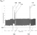
- valve leak frequency profile between inlet valve 50 and outlet valve 52 i.e. the fluid flowpath 28 across the flow balance chamber "B" 42, on a cartridge 30 undergoing a typical cycle is shown.
- the valve leak frequency values are measured every second, a comparison is made between the minimum and maximum valve leak frequency values and plotted as point readings 100 with respect to the Y-axis.
- the first stage of the typical cycle represents the ultrafiltration stage 102 of the cycle, whereas the second stage of the typical cycle represents the flow balance stage 104 of the cycle.
- the blood pump is stopped at 106 and re-started at 108.
- the blood pump is stopped at 110 and re-started at 112.
- any single difference value 100 does not exceed 900 Hz.
- the typical value throughout the cycle for valve leak frequency difference is between 200 Hz and 500 Hz.
- a spike 114 in the measured valve leak frequency difference value is seen during the ultrafiltration stage 102 of the cycle, the spike 114 reaching a maximum value of approximately 830Hz.
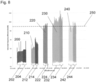
- a cartridge 30 is taken through a series of five typical cycles, numbered as first cycle 200, second cycle 210, third cycle 220, fourth cycle 230 and fifth cycle 240.
- the valve leak frequency difference values are again plotted as point readings with respect to the Y-axis giving a general distribution over the typical cycle time as shown on the X-axis.
- Each cycle 200, 210, 220, 230, 240 includes an ultrafiltration stage 202, 212, 222, 232, 242, a flow balance stage 204, 214, 224, 234, 244, and a purge stage.
- the purge stage follows the flow balance stage 204, 214, 224, 234, 244 for each of the cycles 200, 210, 220, 230, 240 respectively.
- the valve leak frequency difference limit 250 is shown as a dashed line at 1000 Hz.
- the valve leak frequency difference limit 250 may be manipulated depending on the deterioration rates displayed by the cartridge 30.
- valve leak frequency difference values can be seen from the first cycle 200 to the second cycle 210.
- This increase in the valve leak frequency difference value represents a deterioration in the flexible membrane of the cartridge.
- a yet greater increase in the valve leak frequency difference values is seen from the second cycle 210 to the third cycle 220.
- An alarm is raised during the third cycle 220, as the point readings regularly breach the 1000 Hz valve leak frequency difference limit 250.
- Figure 8 shows that the valve leak frequency difference values increase over several cycles with the method described above, with the rate of deterioration being worse after each re-use, until the flexible membrane is effectively plastically deformed. Further re-use of the same cartridge will thus prevent meaningful treatment sessions, as evidenced in the fourth and fifth cycles 230, 240.
- a cartridge 30 is taken through a series of four typical cycles, numbered as first cycle 300, second cycle 310, third cycle 320 and fourth cycle 330.
- the valve leak frequency difference values are again plotted as point readings with respect to the Y-axis giving a general distribution over the typical cycle time as shown on the X-axis.
- Each cycle 300, 310, 320, 330 includes an ultrafiltration stage 302, 312, 322, 332, and a flow balance stage 304, 314, 324, 334, respectively, however, unlike in Figure 8 , no purge stage. Instead, the dialysis machine 10 is switched off just before the purge stage.
- the valve leak frequency difference limit 350 is shown as a dashed line at 1000 Hz.
- Figure 9 shows that the degree of cartridge 30 deterioration is minimal if the purge stage is avoided, thereby allowing an alternative method to re-use the cartridge if necessary. This method of ageing the cartridge 30 does not appear to cause any noticeable deterioration.
- the method of determining a cartridge usage condition records the valve leak frequency during the cycle to obtain a characteristic value, and determines the cartridge usage condition based on the characteristic value.
- the characteristic value may be a single breach of the 1000 Hz valve leak frequency difference limit 350.
- the characteristic value may be a discreet number of breaches of the 1000 Hz valve leak frequency difference limit 350.
- the characteristic value may be a decay rate of the valve leak frequency difference following a spike in the valve leak frequency difference.
- the characteristic value may be the mean, median or modal average valve leak frequency difference during the cycle.
- the processor 98 may be programmed to monitor any of the preceding characteristic values. On receipt of a characteristic value, the process may send a signal to a graphical user interface, or to an audible or visual alarm to indicate the cartridge usage condition or a signal to prevent activation of the dialysis machine cycle.
- the detection system is sensitive enough so that it detects a deterioration of the cartridge membrane before a leak across the valve is established. This allows an operator to prevent use of a cartridge not fit for purpose.
- valve leak frequency is described as being measured using the sensing arrangements including sensing electrodes, other sensing arrangements are envisaged.
- a capacitance probe which provides a non-contacting fluid flowpath sensing arrangement, is also envisaged, as is an inductance probe which is non-contacting.
- Other relaxation oscillator types may be used, such as a transistor based relaxation oscillator.
Landscapes
- Health & Medical Sciences (AREA)
- Engineering & Computer Science (AREA)
- Heart & Thoracic Surgery (AREA)
- Veterinary Medicine (AREA)
- Animal Behavior & Ethology (AREA)
- Public Health (AREA)
- General Health & Medical Sciences (AREA)
- Life Sciences & Earth Sciences (AREA)
- Anesthesiology (AREA)
- Biomedical Technology (AREA)
- Hematology (AREA)
- Mechanical Engineering (AREA)
- Urology & Nephrology (AREA)
- Vascular Medicine (AREA)
- Emergency Medicine (AREA)
- Cardiology (AREA)
- General Engineering & Computer Science (AREA)
- Pulmonology (AREA)
- Medical Informatics (AREA)
- Computer Hardware Design (AREA)
- External Artificial Organs (AREA)
Description
- The present invention relates to a membrane pump usage condition detection system and a method of determining a membrane pump usage condition.
- Fluid pumps, for example blood pumps for the extracorporeal circulation of blood are used in a number of medical applications, for example in hemodialysis, and haemodiafiltration.
- In hemodialysis machines, it is known to use a disposable cartridge comprising a rigid frame defining fluid pathways and chambers and a flexible membrane covering a surface of the cartridge. The cartridge is loaded into a hemodialysis machine, where pressure, typically pneumatic pressure, exerted on the outside surface of the flexible membrane, causes the membrane to move back and forth. This back and forth action in the region of a chamber acts as a fluid pump, which is thus often referred to as a membrane pump. Such a machine is disclosed in
WO 2013/121163 . - The movement may also be used to mix two or more fluids in a chamber, such as bicarbonate and acid to create dialysate.
- The movement of the flexible membrane may also be used to open and close valves defined in the rigid frame of the disposable cartridge. Such a system is disclosed in
WO 2013/110919 . - Because of its use in hemodialysis, in pumping and mixing fluids, the cartridge may be referred to as a haemodialysis pulsatile pumping cartridge. Such a disposable cartridge is typically made of a rigid frame of polyethylene and a flexible membrane of polyvinyl chloride (PVC).
- An instrument for measuring blood volume is disclosed in
JP H06 261872A -
US 2015/0258263 A1 shows a system for balancing flows in a dialysis machine. - In use, the disposable cartridge is loaded in a hemodialysis machine and undergoes repeated deformations in the localised regions of the pump chambers, mixing chambers and valves. In a typical cycle, the machine will perform a priming stage, a treatment stage, including flow balance and ultrafiltration stages following by a purge stage.
- Such a dialysis machine relies on volumetric control. Dosing and mixing of fluids is controlled by the volume of the pump chambers which in turn is affected by the flexibility of the membrane. The specific flexibility of the membrane is therefore essential to the accurate running of the dialysis machine. Similarly, flow of fluids into and out of the pump chambers is controlled by inlet and outlet valves which rely on the deformation of the flexible membrane.
- Repeated deformations gradually cause plastic deformation of the flexible membrane. Thus the disposable cartridges may be engineered to withstand a specific cycle loading, along with a reserve factor. Once used, the disposable cartridge is disposed of and should not be used again.
- Re-use of a cartridge designed for a single cycle, or re-use of a cartridge designed for a specific number of cycles, beyond that number of cycles, may reduce the efficacy of treatment and has the potential to cause damage to the dialysis machine.
- Given the typical make-up of the disposable cartridge, and that a typical cycle ends with a purge stage that washes and empties the cartridge to remove any residual fluids, a used cartridge does not visibly show any distinct features, as compared to an unused cartridge. Therefore there is a risk of cartridge re-use, either deliberate or accidental.
- Valve leak systems are installed in the dialysis machine to detect if any of the valves on the dialysis cartridge are not closing properly, such that there is a leak of fluid through the valve. The valve leak system comprises first and second conductivity electrodes arranged upstream and downstream of the valve respectively. A conductivity measurement is taken across the electrodes when the valve is closed. For a normally functioning valve, a low conductivity, or indeed no conductivity should be detected when the valve is closed. If a valve is leaking however, a high conductivity is detected, as the leaking fluid carries the charge through the valve, between the first and second conductivity electrodes.
- The present invention aims to provide a membrane pump usage condition detection system and a method of determining a membrane pump usage condition and that mitigates one or more of the above problems.
- According to a first aspect of the present invention, there is provided a membrane pump usage condition detection system according to claim 1.
- Thus the system provides an output signal characterising the membrane pump usage condition using data from a valve leak system. This gives an operator of a cartridge incorporating the membrane pump, information concerning the overall condition of the cartridge. As data from the valve leak system is used, the membrane pump usage condition detection system requires no additional hardware.
- The electrical characteristic may be one of conductance, impedance or capacitance or any other electrical characteristic measurable across the valve.
- The detection system further comprises a processor arranged to receive the output signal. The output signal may be stored in the processor. Thus further analysis may be performed on the identified characteristic. Patterns of deliberate or accidental cartridge re-use may then be monitored.
- The membrane pump is provided on a cartridge.
- The processor may calculate the specific number of cartridge uses from the electrical characteristic indicative of the membrane pump usage condition.
- The output signal is an error message preventing further cartridge use. This prevents deliberate or accidental cartridge re-use, or re-use of a cartridge beyond a specified number of uses. This may be notified to the user/operator of the dialysis machine in the form of an audible or visual alarm.
- The comparator may compare the electrical characteristic with a pre-determined threshold value. Alternatively, the comparator may compare the electrical characteristic with a dynamic threshold value.
- The output signal may be provided when the electrical characteristic is above the threshold value. Alternatively, the output signal is provided when the electrical characteristic falls below the threshold value.
- The output signal may be an alarm indicating a net fluid removal error. A valve leak could cause net fluid removal error by not fully filing up or emptying the pump with dialysate. Hence, when a valve leak is detected by measuring the frequency an alarm is generated to stop treatment.
- The processor may be programmed to permit a set number of cartridge re-uses.
- The measuring device may be a pair of electrodes. Alternatively the measuring device may be a pair of capacitance probes.
- According to a second aspect of the present invention, there is provided a method of determining a membrane pump usage condition as set out in
claim 10. - Thus the method of the present invention provides a measure of cartridge deterioration (and re-use) using the data output of the existing valve leak detection system.
- The electrical characteristic may be one of conductance, impedance or capacitance. The cycle may include at least one of a priming stage, a treatment stage, and a purge stage.
- The step of determining the membrane pump usage condition includes recording a characteristic value above a limit value. Alternatively, the step of determining the membrane pump usage condition may include recording a series of characteristic values above a limit value.
- The characteristic value may be a decay rate of the valve leak frequency following a spike in the valve leak frequency. The characteristic values are observed in the data of the valve leak detection system. The so-called background levels change with cartridge re-use. The background level of the valve leak detection system is observed to spike to higher levels during cartridge re-use. The background level of the valve leak detection system is observed to spike to higher levels and then more rapidly decay during cartridge re-use.
- The decay rate of the valve leak frequency following a spike in the valve leak frequency may be indicative of a specific number of cartridge uses. Thus the specific number of cartridge uses may be determined.
- The characteristic value may be the mean, median or modal average valve leak frequency during the cycle. This value may be compared to a signature value for a specific cartridge, providing an indication of the level of cartridge re-use.
- The cartridge usage condition may be determined using a processor provided on the dialysis machine.
- The valve leak frequency may be recorded at a sample rate of 1 sample a second during the cycle. Alternatively, the valve leak frequency may be recorded at an intermittent sample rate during the cycle.
- Embodiments of the present invention will now be described, by way of example only, and with references to the accompanying drawings, in which:
-
Figure 1 is a schematic cross-sectional view of a dialysis machine; -
Figure 2 is a perspective view of a cartridge of the dialysis machine ofFigure 1 ; -
Figure 3 is a plan view of the cartridge ofFigure 2 ; -
Figure 4 is a perspective view of a sensing electrode; -
Figure 5 is a partial cross-sectional view of the cartridge taken at line A-A ofFigure 3 ; -
Figure 6 is a schematic of the fluid flowpath of the sensing arrangement for flow balance pump "B". -
Figure 7 is a valve leak detection frequency profile of a valve on a cartridge undergoing a typical cycle; -
Figure 8 is a valve leak detection frequency profile of a valve on a cartridge undergoing a sequence of cycles; and -
Figure 9 is a valve leak detection frequency profile of a valve on a cartridge undergoing a sequence of cycles, each cycles omitting the purging stage. - A cross section of a
dialysis machine 10 is shown schematically inFigure 1 . Thedialysis machine 10 hasmachine body 22. Themachine body 22 housespneumatic actuators 24 and acontroller 26. Thedialysis machine 10 includes afirst platen 12 and asecond platen 14. The first andsecond platens cartridge 30 is received in a known manner. - The cartridge 30 (see
Figures 2 and3 ) has arigid body 31 covered by aflexible membrane 32, providing a machine facing surface 33. Thecartridge 30 in part embodies pump chambers and valves. In this case, the chambers are flow balance pump chamber "A" 40, flow balance pump chamber "B" 42, dialysate mixingpump chamber 44, acid mixingpump chamber 46 andultrafiltration pump chamber 48. The flow balance pump chamber "A" 40 and flow balance pump chamber "B" 42 each have twoinlet valves 50 and twooutlet valves 52. - The pneumatic operation of each of the
chambers - Furthermore, the two
inlet valves 50 and the twooutlet valves 52 are substantially similar, such that only oneinlet valve 50 and oneoutlet valve 52 shall be described in detail. - Referring back to
Figure 1 , the flow balance pump chamber "A" 40 and inlet andoutlet valves concave cavities 34 formed in therigid body 31 of thecartridge 30 and the flexible membrane of thecartridge 32. Thecartridge 30 definesfluid pathways 28 between the flow balance pump chamber "A" 40 inlet andoutlet valves - In use, the
cartridge 30 is retained between thefirst platen 12 on a first side of thecartridge 30 and thesecond platen 14 on a second side of thecartridge 30. Thesecond platen 14 has acartridge engaging surface 15 and a non-cartridgeengaging surface 17.Cavities 16 are defined within thecartridge engaging surface 15, which correspond to theconcave cavities 34 on thecartridge 30. Afluid port 18 is defined in each of theconcave cavities 16, fluidly connecting thecartridge engaging surface 15 and thenon-cartridge engaging surface 17, of thesecond platen 14. - The
pneumatic actuators 24 are arranged in fluid communication with the first side of thecartridge 30, through thesecond platen 14 via thefluid ports 18, and hence the machine facing surface 33 of theflexible membrane 32. The pump chambers and valves are operated pneumatically by actuating theflexible membrane 32 using thepneumatic actuators 24 provided in themachine body 22. In an alternative embodiment the pump chambers and valves are operated hydraulically. - The pump chambers and valves are provided with
sensing arrangements 60, each of which include two sensing electrodes, generally termed 70 (seeFigures 4 and 5 ). Thesensing electrodes 70 are rotationally symmetrical and are made of a conductive material. Thesensing electrodes 70 include apointed tip 71. Thesensing electrodes 70 are mounted in therigid body 31 of thecartridge 30. The pointedtip 71 is arranged to face the second side of thecartridge 30 and theflexible membrane 32. - The
sensing arrangements 60 monitor the flow of fluids through the pump chambers and valves along the various fluid pathways. Referring toFigure 6 , one such fluid pathway is thefluid pathway 28 associated with the flow balance pump chamber "B" 42. As thesensing arrangements 60 are substantially similar, only thesensing arrangement 60 associated with the flow balance pump chamber "B" 42 shall be described in detail. - The flow balance pump chamber "B" sensing
arrangement 60 is arranged with an inletvalve sensing electrode 72 and outletvalve sensing electrode 82. The inletvalve sensing electrode 72 is fixed to therigid body 31 of thecartridge 30 with thepointed sensing tip 71 exposed to thefluid flowpath 28 at the entrance to theinlet valve 50. The outletvalve sensing electrode 82 is fixed to therigid body 31 of thecartridge 30 with thepointed sensing tip 71 exposed to thefluid flowpath 28 at the exit of theoutlet valve 52. - Thus the inlet
valve sensing electrode 72 is provided upstream of the flow balance pump chamber "B" 42, and outletvalve sensing electrode 82 is provided downstream of the flow balance pump chamber "B" 42. - When the
cartridge 30 is loaded into thedialysis machine 10, the inletvalve sensing electrode 72 and outletvalve sensing electrode 82 line up with sprungcontacts second platen 14, sandwiching theflexible membrane 32 therebetween. - The sprung
contacts processor 98, incorporating a sensor circuit, a comparator and a power source, provided in themachine body 22 viaelectrical connectors - Thus inlet
valve sensing electrode 72 and outletvalve sensing electrode 82 are electrically connected to theprocessor 98 through theflexible membrane 32. The inletvalve sensing electrode 72 and outletvalve sensing electrode 82, together with the sprungcontacts processor 98 andrespective connectors sensing arrangement 60. - In use at least one of the
inlet valve 50 and theoutlet valve 52 will always be closed. That is, there are three modes of operation. In an idle mode, both theinlet valve 50 and theoutlet valve 52 are closed. Thus there should be no continuous flowpath between the inletvalve sensing electrode 72 and the outletvalve sensing electrode 82. In a fill mode, theinlet valve 50 is open, and theoutlet valve 52 is closed. This allows flow balance pump chamber "B" to be filled. However, there should still be no continuous flowpath between the inletvalve sensing electrode 72 and the outletvalve sensing electrode 82, as the outlet valve is closed. In an empty mode, theinlet valve 50 is closed, and theoutlet valve 52 is open. This allows flow balance pump chamber "B" to be emptied. However, there should still be no continuous flowpath between the inletvalve sensing electrode 72 and the outletvalve sensing electrode 82, as theinlet valve 50 is closed. Thus the valve leak system may detect when either of the inlet oroutlet valves sensing arrangement 60 shown inFigure 6 . - During operation of the
dialysis machine 10, thesensing arrangements 60 are used to detect leakage across the pump chambers and valves of the Dialysis Machine. - The sensor circuit of the
processor 98, includes an operational amplifier based relaxation oscillator whose frequency is determined by electrical conductance of the fluid path. - In use, an alternating potential difference from the power source is applied across the
fluid flowpath 28 by the inletvalve sensing electrode 72. The conductance of thefluid flowpath 28 between theinlet valve 50 andoutlet valve 52 of the flow balance pump chamber "B" 42 is measured at the outletvalve sensing electrode 82 by measuring the potential difference detected at the outletvalve sensing electrode 82, as will be described in more detail below. The potential differential provides an indication the conductivity of thefluid flowpath 28. The relaxation oscillator ensures that thesensing arrangement 60 operates with an alternating current with minimal direct current offset. This reduces the galvanic effects on the inletvalve sensing electrode 72 and the outletvalve sensing electrode 82. - The sensor circuit of the
processor 98 generates the pulse train from the relaxation oscillator which is sent through thesensing arrangement 60, to output at theprocessor 98. The output at the processor is a series of pulses. From this series of pulses, a frequency is determined by measuring the time between the pulses, and hence fluid conductivity. This frequency value is known as the valve leak frequency. - The
sensing arrangement 60 detects a valve leak in the inlet andoutlet valves valves outlet valves fluid flowpath 28 as a means to determine this failure. Thus in normal operation of the Dialysis Machine, there should never be a conductive path across the whole of the pump, from before theinlet valve 50 to after theoutlet valve 52, that has a conductivity of a value equal to or greater than a limit value set by the particular geometry of the cartridge in question. If a conductive path is seen, this may be indicative of one of thevalves - Hence the valve leak detection system measures a valve leak frequency value. The valve leak signal is generated by an oscillator and the frequency of the signal is determined by the feedback resistor. The sensing electrodes are connected in parallel to the feedback resistor so that a lower impedance across the valves would cause the total feedback resistor value to decrease, increasing the oscillating frequency.
- During normal operation of an exemplary Dialysis Machine having an exemplary cartridge, the relaxation oscillator is tuned to generate a signal of 6 kHz for a resistance of 10 kOhms across the sensing electrodes. The expected detected valve leak frequency value is between 3 kHz and 4 kHz. Should a valve leak frequency value in excess of 6 kHz be detected, a valve leak has occurred.
- The valve leak detection system described above may be used to determine membrane pump usage and hence cartridge usage.
- A partial valve leak (e.g. due to re-used cartridges) is detected when the variation of detected valve leak frequency value within a pumping cycle increases.
- A variation in the detected valve leak frequency value is detected by the comparator within the
processor 98 measuring the difference between the minimum and maximum valve leak frequency values measured within one pump cycle. - For the normal operation of an exemplary Dialysis Machine having an exemplary cartridge referred to above, variation of valve leak frequency value is between 200Hz and 500 Hz. Variations above 1 kHz are considered to be partial valve leak. Thus for this exemplary Dialysis Machine having an exemplary cartridge, the pre-determined threshold value is a valve leak frequency value difference of 1 kHz.
- The value used for the partial valve leak is not the absolute frequency but the variation of the frequency within a pumping cycle. When the valve is partially leaking (e.g. due to re-use of cartridges) the frequency signal is not as stable as it normally is: maximum relative difference of the valve leak frequency value within one pump cycle is more than 1 kHz. Normal expected values of absolute frequency are 3 kHz to 4 kHz with a variation of less than 1 kHz within a pumping cycle.
- As the valve leak signal is generated by an oscillator and the frequency of the signal is determined by the feedback resistor, a dynamic threshold value for the valve leak frequency value difference may be used instead of the pre-determined threshold value.
- The effects on a
cartridge 30 during a dialysis treatment cycle can be represented by a typical test cycle. A typical test cycle includes three main stages, flow balance, ultrafiltration and purge. In the first 30 minutes, thedialysis machine 10 is taken through a flow balance stage of the test cycle. The flow balance stage tests the flow balance valves. During the next 30 minutes, thedialysis machine 10 is taken through an ultrafiltration stage of the test cycle. The ultrafiltration stage tests the ultrafiltration valves. The test cycle is then ended with a purge stage. The purge stage empties thecartridge 30 of all dialysate fluids, and cleans the fluid flow paths with reverse osmosis water. - In order to determine the deterioration rates, the
same cartridge 30 is forced through repeated test cycles. - With reference to
Figure 7 , a valve leak frequency profile betweeninlet valve 50 andoutlet valve 52, i.e. thefluid flowpath 28 across the flow balance chamber "B" 42, on acartridge 30 undergoing a typical cycle is shown. The valve leak frequency values are measured every second, a comparison is made between the minimum and maximum valve leak frequency values and plotted aspoint readings 100 with respect to the Y-axis. A general distribution over the typical cycle time as shown on the X-axis. The first stage of the typical cycle represents theultrafiltration stage 102 of the cycle, whereas the second stage of the typical cycle represents theflow balance stage 104 of the cycle. During ultrafiltration the blood pump is stopped at 106 and re-started at 108. Similarly, during flow balance, the blood pump is stopped at 110 and re-started at 112. - As can be seen in
Figure 7 , whilst the measured valve leak frequency difference varies during a normal treatment session, the magnitude of anysingle difference value 100 does not exceed 900 Hz. The typical value throughout the cycle for valve leak frequency difference is between 200 Hz and 500 Hz. Aspike 114 in the measured valve leak frequency difference value is seen during theultrafiltration stage 102 of the cycle, thespike 114 reaching a maximum value of approximately 830Hz. - With reference to
Figure 8 , acartridge 30 is taken through a series of five typical cycles, numbered asfirst cycle 200,second cycle 210,third cycle 220,fourth cycle 230 andfifth cycle 240. For each cycle, the valve leak frequency difference values are again plotted as point readings with respect to the Y-axis giving a general distribution over the typical cycle time as shown on the X-axis. Eachcycle ultrafiltration stage flow balance stage flow balance stage cycles - The valve leak
frequency difference limit 250 is shown as a dashed line at 1000 Hz. The valve leakfrequency difference limit 250 may be manipulated depending on the deterioration rates displayed by thecartridge 30. - An increase in the valve leak frequency difference values can be seen from the
first cycle 200 to thesecond cycle 210. This increase in the valve leak frequency difference value represents a deterioration in the flexible membrane of the cartridge. A yet greater increase in the valve leak frequency difference values is seen from thesecond cycle 210 to thethird cycle 220. An alarm is raised during thethird cycle 220, as the point readings regularly breach the 1000 Hz valve leakfrequency difference limit 250. - Thus
Figure 8 shows that the valve leak frequency difference values increase over several cycles with the method described above, with the rate of deterioration being worse after each re-use, until the flexible membrane is effectively plastically deformed. Further re-use of the same cartridge will thus prevent meaningful treatment sessions, as evidenced in the fourth andfifth cycles - With reference to
Figure 9 , acartridge 30 is taken through a series of four typical cycles, numbered asfirst cycle 300,second cycle 310,third cycle 320 andfourth cycle 330. For each cycle, the valve leak frequency difference values are again plotted as point readings with respect to the Y-axis giving a general distribution over the typical cycle time as shown on the X-axis. Eachcycle ultrafiltration stage flow balance stage Figure 8 , no purge stage. Instead, thedialysis machine 10 is switched off just before the purge stage. - The valve leak
frequency difference limit 350 is shown as a dashed line at 1000 Hz. -
Figure 9 shows that the degree ofcartridge 30 deterioration is minimal if the purge stage is avoided, thereby allowing an alternative method to re-use the cartridge if necessary. This method of ageing thecartridge 30 does not appear to cause any noticeable deterioration. - Thus the method of determining a cartridge usage condition records the valve leak frequency during the cycle to obtain a characteristic value, and determines the cartridge usage condition based on the characteristic value. The characteristic value may be a single breach of the 1000 Hz valve leak
frequency difference limit 350. The characteristic value may be a discreet number of breaches of the 1000 Hz valve leakfrequency difference limit 350. The characteristic value may be a decay rate of the valve leak frequency difference following a spike in the valve leak frequency difference. The characteristic value may be the mean, median or modal average valve leak frequency difference during the cycle. Theprocessor 98 may be programmed to monitor any of the preceding characteristic values. On receipt of a characteristic value, the process may send a signal to a graphical user interface, or to an audible or visual alarm to indicate the cartridge usage condition or a signal to prevent activation of the dialysis machine cycle. - Thus the detection system is sensitive enough so that it detects a deterioration of the cartridge membrane before a leak across the valve is established. This allows an operator to prevent use of a cartridge not fit for purpose.
- Although the valve leak frequency is described as being measured using the sensing arrangements including sensing electrodes, other sensing arrangements are envisaged. A capacitance probe, which provides a non-contacting fluid flowpath sensing arrangement, is also envisaged, as is an inductance probe which is non-contacting. Other relaxation oscillator types may be used, such as a transistor based relaxation oscillator.
Claims (18)
- A membrane pump usage condition detection system (60) comprising:a cartridge (30) having a deformable membrane,a membrane pump provided on the cartridge (30) and defining a flow path (28) arranged to be opened and closed by at least one valve (50, 52),a measuring device (72, 82);a comparator;a processor; anda signal generator, whereinthe measuring device (72, 82) is configured to determine an electrical characteristic between two points on the flow path of the membrane pump, one point arranged upstream of the at least one valve (50, 52) and the other point arranged downstream of the at least one valve (50, 52),whereby the measuring device (72, 82) measures the electrical characteristic when the at least one valve (50, 52) is closed, andwherein the comparator is configured to monitor the electrical characteristic, andthe signal generator is arranged to provide an output signal when the electrical characteristic is indicative of a deterioration of the deformable membrane, and the processor is arranged to receive the output signal.
- A membrane pump usage condition detection system (60) according to claim 1 wherein the electrical characteristic is one of conductance, impedance or capacitance.
- A membrane pump usage condition detection system (60) according to claims 1 or 2 wherein the output signal is stored in the processor (98).
- A membrane pump usage condition detection system (60) according to claim 1 wherein the processor (98) calculates the specific number of cartridge (30) uses from the electrical characteristic indicative of the deterioration of the deformable membrane.
- A membrane pump usage condition detection system (60) according to claim 1 or claim 4, wherein the output signal is an error message preventing further cartridge (30) use.
- A membrane pump usage condition detection system (60) according to any preceding claim wherein the comparator compares the electrical characteristic with a pre-determined threshold value, or wherein the comparator compares the electrical characteristic with a dynamic threshold value.
- A membrane pump usage condition detection system (60) according to claim 6 wherein the output signal is provided when the electrical characteristic is above the threshold value or wherein the output signal is provided when the electrical characteristic falls below the threshold value.
- A membrane pump usage condition detection system (60) according to any preceding claims wherein processor (98) is programmed to permit a set number of cartridge (30) re-uses.
- A membrane pump usage condition detection system (60) according to any preceding claim wherein the measuring device is a pair of electrodes (72, 82) or wherein the measuring device is a pair of capacitance probes.
- A method of determining a membrane pump usage condition comprising the steps of:providing a dialysis machine (10) including a cartridge (30) having a deformable membrane (32), the cartridge (30) and deformable membrane (32) together defining a membrane pump, the membrane pump defining a flow path (28) arranged to be opened and closed by at least one valve (50, 52), a measuring device (72, 82), a comparator; and a signal generator,configuring the measuring device for determining an electrical characteristic between two points on the flow path (28) of the membrane pump, one point arranged upstream of the at least one valve (50, 52) and the other point arranged downstream of the at least one valve (50, 52),operating the dialysis machine (30) through a cycle (200, 210, 220, 230),measuring the electrical characteristic whenever the at least one valve (50, 52) is closed,monitoring the electrical characteristic throughout the cycle (200, 210, 220, 230) using the comparator,providing an output signal when the electrical characteristic is indicative of a deterioration of the deformable membrane.
- A method of determining a membrane pump usage condition according to claim 10 wherein the output signal is an error message preventing further cartridge (30) use.
- A method of determining a membrane pump usage condition according to claim 10 wherein the electrical characteristic is one of conductance, impedance or capacitance.
- A method of determining a membrane pump usage condition according to claims 10 or 11 wherein the step of monitoring the electrical characteristic includes recording a characteristic value above a limit value or wherein the step of monitoring the electrical characteristic includes recording a series of characteristic values above a limit value.
- A method of determining a membrane pump usage condition according to claim 10 wherein the characteristic value is a decay rate of the valve leak frequency difference following a spike (114) in the valve leak frequency difference.
- A method of determining a membrane pump usage condition according to claim 14 wherein the decay rate of the valve leak frequency difference following a spike in the valve leak frequency difference is indicative of a specific number of cartridge (30) uses.
- A method of determining a membrane pump usage condition according to claim 10 wherein the characteristic value is the mean, median or modal average valve leak frequency difference during the cycle (200, 210, 220, 230).
- A method of determining a membrane pump usage condition according to any of the claims 10 to 15 wherein the deterioration of the deformable membrane is determined using a processor (98) provided on the dialysis machine (10).
- A method of determining a membrane pump usage condition according to any of claims 14 to 16 wherein the valve leak frequency is recorded at a sample rate of 1 sample a second during the cycle (200, 210, 220, 230) or wherein the valve leak frequency is recorded at an intermittent sample rate during the cycle (200, 210, 220, 230).
Applications Claiming Priority (2)
| Application Number | Priority Date | Filing Date | Title |
|---|---|---|---|
| GB1602391.3A GB2547214A (en) | 2016-02-10 | 2016-02-10 | Membrane pump usage condition detection |
| PCT/GB2017/050235 WO2017137723A1 (en) | 2016-02-10 | 2017-01-31 | Membrane pump usage condition detection |
Publications (2)
| Publication Number | Publication Date |
|---|---|
| EP3414458A1 EP3414458A1 (en) | 2018-12-19 |
| EP3414458B1 true EP3414458B1 (en) | 2025-06-25 |
Family
ID=55642099
Family Applications (1)
| Application Number | Title | Priority Date | Filing Date |
|---|---|---|---|
| EP17702941.0A Active EP3414458B1 (en) | 2016-02-10 | 2017-01-31 | Membrane pump usage condition detection |
Country Status (4)
| Country | Link |
|---|---|
| US (2) | US12163513B2 (en) |
| EP (1) | EP3414458B1 (en) |
| GB (1) | GB2547214A (en) |
| WO (1) | WO2017137723A1 (en) |
Families Citing this family (14)
| Publication number | Priority date | Publication date | Assignee | Title |
|---|---|---|---|---|
| GB201305755D0 (en) | 2013-03-28 | 2013-05-15 | Quanta Fluid Solutions Ltd | Re-Use of a Hemodialysis Cartridge |
| GB201314512D0 (en) | 2013-08-14 | 2013-09-25 | Quanta Fluid Solutions Ltd | Dual Haemodialysis and Haemodiafiltration blood treatment device |
| GB201409796D0 (en) | 2014-06-02 | 2014-07-16 | Quanta Fluid Solutions Ltd | Method of heat sanitization of a haemodialysis water circuit using a calculated dose |
| GB201523104D0 (en) | 2015-12-30 | 2016-02-10 | Quanta Fluid Solutions Ltd | Dialysis machine |
| GB2547214A (en) * | 2016-02-10 | 2017-08-16 | Quanta Fluid Solutions Ltd | Membrane pump usage condition detection |
| GB201622119D0 (en) | 2016-12-23 | 2017-02-08 | Quanta Dialysis Tech Ltd | Improved valve leak detection system |
| GB201701740D0 (en) | 2017-02-02 | 2017-03-22 | Quanta Dialysis Tech Ltd | Phased convective operation |
| GB201703048D0 (en) | 2017-02-24 | 2017-04-12 | Quanta Dialysis Tech Ltd | Testing rotor engagement of a rotary peristaltic pump |
| GB201705273D0 (en) | 2017-03-31 | 2017-05-17 | Quanta Dialysis Tech Ltd | Data storage amd exchange by medical device components |
| GB2563431B (en) * | 2017-06-15 | 2021-12-22 | Quanta Dialysis Technologies Ltd | Blood treatment machine |
| GB201710546D0 (en) | 2017-06-30 | 2017-08-16 | Quanta Dialysis Tech Ltd | Dialysis systems, devices and methods |
| USD907211S1 (en) | 2017-09-28 | 2021-01-05 | Quanta Dialysis Technologies Ltd. | Dialysis machine |
| GB2584335A (en) | 2019-05-31 | 2020-12-02 | Quanta Dialysis Technologies Ltd | Source container connector |
| GB2637137A (en) | 2024-01-09 | 2025-07-16 | Quanta Dialysis Tech Ltd | Dialysis fluid cartridge |
Family Cites Families (250)
| Publication number | Priority date | Publication date | Assignee | Title |
|---|---|---|---|---|
| CA81430A (en) | 1902-12-12 | 1903-06-16 | John D. Mceachren | Drying apparatus |
| US2696173A (en) | 1950-12-23 | 1954-12-07 | Jensen Thormod | Fluid pump |
| US3338171A (en) | 1965-09-15 | 1967-08-29 | Du Pont | Pneumatically operable diaphragm pumps |
| US3468261A (en) | 1967-01-23 | 1969-09-23 | Altec Ges Fur Allg Landtechnik | Pump |
| FR1552305A (en) | 1967-12-15 | 1969-01-03 | ||
| US3606592A (en) | 1970-05-20 | 1971-09-20 | Bendix Corp | Fluid pump |
| US4370983A (en) | 1971-01-20 | 1983-02-01 | Lichtenstein Eric Stefan | Computer-control medical care system |
| US3774762A (en) | 1971-01-20 | 1973-11-27 | E Lichtenstein | Analogue fluid flow programming structures |
| DE2116456A1 (en) | 1971-04-03 | 1972-10-12 | Pumpenfabrik Urach, 7417 Urach | Diaphragm pump for conveying liquid or gaseous media |
| US3753493A (en) | 1971-04-23 | 1973-08-21 | E Mellor | Artificial kidney cleaning apparatus |
| GB1418181A (en) | 1973-02-27 | 1975-12-17 | Cole E M | Ultrasonic detection of inclusions in a fluid flowing within a tube |
| US3972320A (en) | 1974-08-12 | 1976-08-03 | Gabor Ujhelyi Kalman | Patient monitoring system |
| FR2310136A1 (en) | 1975-05-07 | 1976-12-03 | Bernas Medical | Automatic cleaner for dialysers for artificial kidneys - incorporating programming of washing, rinsing and sterilising several dialysers simultaneously |
| US4070725A (en) | 1975-11-07 | 1978-01-31 | Cornelius Eng | Combined pump and siphon |
| US4142845A (en) | 1976-02-20 | 1979-03-06 | Lepp William A | Dialysis pump system having over-center cam tracks to lock rollers against tubing |
| US4161264A (en) | 1977-06-17 | 1979-07-17 | Johnson Bryan E | Fluid metering and mixing device having inlet and outlet valves |
| US4205686A (en) | 1977-09-09 | 1980-06-03 | Picker Corporation | Ultrasonic transducer and examination method |
| DE2950381A1 (en) | 1979-12-14 | 1981-06-19 | Boehringer Mannheim Gmbh, 6800 Mannheim | METHOD AND REAGENT FOR DETERMINING TRIGLYCERIDES |
| US4324662A (en) | 1979-12-28 | 1982-04-13 | Baxter Travenol Laboratories, Inc. | Flow reversal in a dialyzer |
| US4366061A (en) | 1980-01-23 | 1982-12-28 | Cordis Dow Corp. | Automated diaphragm apparatus and method for controlling negative pressure hemodialysis treatment |
| ATE10670T1 (en) | 1980-12-29 | 1984-12-15 | Lewa Herbert Ott Gmbh + Co. | DIAPHRAGM PUMP WITH RELIEVED CLAMPED DIAPHRAGM. |
| US4353990A (en) | 1981-02-09 | 1982-10-12 | Minnesota Mining And Manufacturing Company | Sanitation indicator |
| US4534755A (en) | 1982-02-22 | 1985-08-13 | Hoccum Developments Limited | Centrifuges |
| DE3225323C2 (en) | 1982-07-07 | 1984-05-24 | Messerschmitt-Bölkow-Blohm GmbH, 8012 Ottobrunn | Connecting rod made of fiber-reinforced plastic |
| US4494912A (en) | 1982-09-16 | 1985-01-22 | Pauliukonis Richard S | Energy conserving air pump |
| US4534756A (en) | 1983-04-11 | 1985-08-13 | Ivac Corporation | Fault detection apparatus and method for parenteral infusion system |
| USD277991S (en) | 1983-05-12 | 1985-03-12 | Marketing International, Inc. | Cart for handling biological tissue |
| DE3326786A1 (en) | 1983-07-25 | 1985-02-14 | Fresenius AG, 6380 Bad Homburg | PUMP BED FOR A ROLL PUMP |
| FR2558063B1 (en) | 1984-01-18 | 1987-02-20 | Hospal Ind | ARTIFICIAL KIDNEY WITH SINGLE NEEDLE |
| CS248305B1 (en) | 1984-06-18 | 1987-02-12 | Miroslav Skala | Blood cleaning instrument |
| US5643201A (en) | 1984-07-09 | 1997-07-01 | Peabody; Alan M. | Continuous peritoneal dialysis apparatus |
| US4771792A (en) | 1985-02-19 | 1988-09-20 | Seale Joseph B | Non-invasive determination of mechanical characteristics in the body |
| US4666598A (en) | 1985-06-25 | 1987-05-19 | Cobe Laboratories, Inc. | Apparatus for use with fluid flow transfer device |
| US4648869A (en) | 1985-12-04 | 1987-03-10 | American Hospital Supply Corporation | Automatic infiltration detection system and method |
| US4828543A (en) | 1986-04-03 | 1989-05-09 | Weiss Paul I | Extracorporeal circulation apparatus |
| US4710163A (en) | 1986-06-06 | 1987-12-01 | Ivac Corporation | Detection of fluid flow faults in the parenteral administration of fluids |
| US4897184A (en) | 1986-10-31 | 1990-01-30 | Cobe Laboratories, Inc. | Fluid flow apparatus control and monitoring |
| USD308249S (en) | 1987-09-25 | 1990-05-29 | Delmed, Inc. | Peritoneal dialysis machine |
| US4979940A (en) | 1988-03-08 | 1990-12-25 | Baxter International Inc. | Infusion system, methodology, and algorithm for identifying patient-induced pressure artifacts |
| US5012197A (en) | 1988-04-19 | 1991-04-30 | Volkhard Seiffert | Apparatus and method for determining the relative percentages of components in a mixture |
| WO1990007648A1 (en) | 1988-12-29 | 1990-07-12 | Chang, Victor, Peter | Diaphragm pump |
| US5000664A (en) | 1989-06-07 | 1991-03-19 | Abbott Laboratories | Apparatus and method to test for valve leakage in a pump assembly |
| US5252213A (en) | 1989-06-20 | 1993-10-12 | University Of Washington | Dry dialysate composition |
| US4969991A (en) | 1989-08-30 | 1990-11-13 | Valadez Gerardo M | Water purifying and dispensing system |
| US5103211A (en) | 1989-11-02 | 1992-04-07 | Ivac Corporation | Apparatus for detecting fluid line occlusion |
| US5055198A (en) | 1990-03-07 | 1991-10-08 | Shettigar U Ramakrishna | Autologous blood recovery membrane system and method |
| JP2863597B2 (en) | 1990-03-30 | 1999-03-03 | 株式会社東芝 | Clamp circuit |
| NL9000867A (en) | 1990-04-12 | 1991-11-01 | Bredel Exploitatie Bv | HOSE PUMP WITH RETRACTABLE PRESS BODIES. |
| US5095910A (en) | 1990-04-18 | 1992-03-17 | Advanced Technology Laboratories, Inc. | Ultrasonic imaging of biopsy needle |
| US5032265A (en) | 1990-06-20 | 1991-07-16 | Millipore Corporation | Method and system for producing sterile aqueous solutions |
| US5232434A (en) | 1990-10-05 | 1993-08-03 | Aisin Seiki Kabushiki Kaisha | Fluid feeding pump unit |
| US5558347A (en) | 1990-12-31 | 1996-09-24 | Specialist Sealing Limited | Seal |
| JP3041837B2 (en) * | 1991-02-20 | 2000-05-15 | 東洋紡績株式会社 | Blood flow measurement method and artificial heart drive system |
| US5665307A (en) | 1991-03-27 | 1997-09-09 | Fresenius Ag | Aqueous disinfecting agent |
| USD344339S (en) | 1991-08-23 | 1994-02-15 | Terumo Kabushiki Kaisha | Automatic blood separator |
| USD341890S (en) | 1991-10-25 | 1993-11-30 | Electromedics, Inc. | Autotransfusion system housing |
| DE4138140C2 (en) | 1991-11-20 | 1993-12-23 | Fresenius Ag | Device for disinfecting hemodialysis machines with a powdered concentrate |
| USD347896S (en) | 1992-04-30 | 1994-06-14 | Intravascular Research Limited | Medical ultrasound image display unit |
| US5586873A (en) | 1992-06-18 | 1996-12-24 | Novak; Pavel | Tube pump with retractable rollers |
| US5476368A (en) | 1992-08-20 | 1995-12-19 | Ryder International Corporation | Sterile fluid pump diaphragm construction |
| WO1994005345A1 (en) | 1992-09-02 | 1994-03-17 | Valery Viktorovich Skobelev | Pump for biological liquids |
| USD351470S (en) | 1993-03-03 | 1994-10-11 | Baxter International Inc. | Peritoneal dialysis cycler |
| US5350357A (en) | 1993-03-03 | 1994-09-27 | Deka Products Limited Partnership | Peritoneal dialysis systems employing a liquid distribution and pumping cassette that emulates gravity flow |
| JPH06261872A (en) | 1993-03-11 | 1994-09-20 | Toyobo Co Ltd | Blood volume measuring method and apparatus |
| US5385540A (en) | 1993-05-26 | 1995-01-31 | Quest Medical, Inc. | Cardioplegia delivery system |
| AU5352594A (en) * | 1993-08-23 | 1995-03-21 | W.L. Gore & Associates, Inc. | Pre-failure warning pump diaphragm |
| JP3199938B2 (en) * | 1993-12-17 | 2001-08-20 | 日機装株式会社 | Leak detection device for shutoff mechanism in flow passage |
| GB9405523D0 (en) | 1994-03-21 | 1994-05-04 | Graseby Medical Ltd | Pumping and pressure detection using flexible tubes |
| US5476792A (en) | 1994-04-05 | 1995-12-19 | Temple Division, Air Liquide America Corporation | Time-temperature indicator devices |
| SE510026C2 (en) | 1994-09-23 | 1999-04-12 | Gambro Ab | Disinfection device for dialysis machine |
| USD370979S (en) | 1994-11-10 | 1996-06-18 | Pall Corporation | Fluid processing system |
| AUPN012194A0 (en) | 1994-12-16 | 1995-01-19 | University Of Queensland, The | Alumino-silicate derivatives |
| US6153102A (en) | 1995-02-13 | 2000-11-28 | Aksys, Ltd. | Disinfection of dead-ended lines in medical instruments |
| US5788851A (en) | 1995-02-13 | 1998-08-04 | Aksys, Ltd. | User interface and method for control of medical instruments, such as dialysis machines |
| US5591344A (en) | 1995-02-13 | 1997-01-07 | Aksys, Ltd. | Hot water disinfection of dialysis machines, including the extracorporeal circuit thereof |
| US5650071A (en) | 1995-06-07 | 1997-07-22 | Cobe Laboratories, Inc. | Technique for priming and recirculating fluid through a dialysis machine to prepare the machine for use |
| WO1997003609A1 (en) | 1995-07-16 | 1997-02-06 | Ultra-Guide Ltd. | Free-hand aiming of a needle guide |
| US5772624A (en) | 1995-07-20 | 1998-06-30 | Medisystems Technology Corporation | Reusable blood lines |
| US5653456A (en) | 1995-07-21 | 1997-08-05 | Mough; Bryan M. | Ski system for ice fishing shanties |
| SE508374C2 (en) | 1995-09-12 | 1998-09-28 | Gambro Med Tech Ab | Method and apparatus for detecting the condition of a blood vessel access |
| US5759017A (en) | 1996-01-31 | 1998-06-02 | Medtronic Electromedics, Inc. | Peristaltic pump and tube loading system |
| US5727550A (en) | 1996-04-09 | 1998-03-17 | Lectec Corporation | Dual purpose ultrasonic biomedical couplant pad and electrode |
| SE510126C2 (en) | 1996-06-13 | 1999-04-19 | Althin Medical Ab | Dialysis machine with movable control panel |
| US5882300A (en) | 1996-11-07 | 1999-03-16 | Spacelabs Medical, Inc. | Wireless patient monitoring apparatus using inductive coupling |
| USD395085S (en) | 1997-04-25 | 1998-06-09 | Aksys, Ltd. | Dialysis machine |
| DE19734002C1 (en) | 1997-08-06 | 1998-09-17 | Fresenius Medical Care De Gmbh | Blood dialysis process with process monitoring system on dialysis machine |
| DE59814205D1 (en) | 1997-08-13 | 2008-05-21 | Fresenius Medical Care De Gmbh | A blood treatment device comprising a device for determining parameters of hemodialysis and methods for its determination |
| US5957670A (en) | 1997-08-26 | 1999-09-28 | Wilden Pump & Engineering Co. | Air driven diaphragm pump |
| US5995910A (en) | 1997-08-29 | 1999-11-30 | Reliance Electric Industrial Company | Method and system for synthesizing vibration data |
| CH692570A5 (en) | 1997-12-05 | 2002-08-15 | Peter F Meier | Apparatus for monitoring a catheter device. |
| GB9801138D0 (en) | 1998-01-20 | 1998-03-18 | Eastman Kodak Co | Time temperature indicator devices |
| EP1119404B2 (en) | 1998-07-31 | 2013-05-01 | Nephros, Inc. | Device for efficient hemodiafiltration |
| US6331252B1 (en) | 1998-07-31 | 2001-12-18 | Baxter International Inc. | Methods for priming a blood compartment of a hemodialyzer |
| US6132378A (en) | 1998-08-10 | 2000-10-17 | Marino; Sharon | Cover for ultrasound probe |
| SE521219C2 (en) | 1998-10-23 | 2003-10-14 | Gambro Ab | Method and apparatus for reducing the degradation of heat sensitive components in medical substances during heat sterilization |
| JP2000130334A (en) * | 1998-10-26 | 2000-05-12 | Takuma Co Ltd | Diaphragm pump, diaphragm damage detection method, and ammonia absorption refrigerator including the same |
| DK173498B1 (en) | 1998-11-19 | 2001-01-08 | Coloplast As | An ostomy appliance |
| FR2790041B1 (en) | 1999-02-23 | 2002-01-18 | Fresenius Vial | METHOD FOR CONTROLLING A PUMPING DEVICE COMPRISING A PUMP PROVIDED WITH A FLEXIBLE TUBE AND DEVICE FOR IMPLEMENTING THE METHOD |
| SE9901165D0 (en) | 1999-03-30 | 1999-03-30 | Gambro Lundia Ab | Method, apparatus and components of dialysis systems |
| SE9903331D0 (en) | 1999-09-16 | 1999-09-16 | Gambro Lundia Ab | Method and apparatus for sterilizing a heat sensitive fluid |
| WO2000063658A2 (en) | 1999-04-15 | 2000-10-26 | Ultraguide Ltd. | Apparatus and method for detecting the bending of medical invasive tools in medical interventions |
| BR0009799B1 (en) | 1999-04-30 | 2009-01-13 | control and continuous hemoinfiltration systems. | |
| US6382923B1 (en) | 1999-07-20 | 2002-05-07 | Deka Products Ltd. Partnership | Pump chamber having at least one spacer for inhibiting the pumping of a gas |
| US6723062B1 (en) * | 1999-09-03 | 2004-04-20 | Baxter International Inc. | Fluid pressure actuated blood pumping systems and methods with continuous inflow and pulsatile outflow conditions |
| US6261065B1 (en) | 1999-09-03 | 2001-07-17 | Baxter International Inc. | System and methods for control of pumps employing electrical field sensing |
| US20040215129A1 (en) | 1999-09-16 | 2004-10-28 | Gambro Ab | Method and cycler for the administration of a peritoneal dialysis fluid |
| IT1308861B1 (en) | 1999-11-02 | 2002-01-11 | Gambro Dasco Spa | METHOD OF CONTROL OF A DIALYSIS EQUIPMENT DEDICATED TO THE IMPLEMENTATION OF THE AFBK DIALYTIC TECHNIQUE AND RELATED |
| US7347849B2 (en) | 2001-05-24 | 2008-03-25 | Nxstage Medical, Inc. | Modular medical treatment replaceable component |
| US6251279B1 (en) | 1999-12-09 | 2001-06-26 | Dialysis Systems, Inc. | Heat disinfection of a water supply |
| DE10012904B4 (en) | 2000-03-16 | 2004-08-12 | Lewa Herbert Ott Gmbh + Co | Membrane clamping with elasticity compensation |
| US6645176B1 (en) | 2000-04-28 | 2003-11-11 | Medtronic, Inc. | Spring loaded implantable drug infusion device |
| DE10024447A1 (en) | 2000-05-19 | 2001-11-29 | Asw Aqua System Wassertechnik | Process for producing ultrapure water and device for carrying out the process |
| US20030034305A1 (en) | 2001-01-05 | 2003-02-20 | Gambro, Inc. | Purified water supply system for high demand devices and applications |
| WO2002066833A1 (en) | 2001-02-20 | 2002-08-29 | N.E. Holm A/S | Hose pump |
| WO2002081917A1 (en) | 2001-04-09 | 2002-10-17 | Pumping Systems Technologies Pty Limited | Displacement pump and ancillary equipment |
| US6733476B2 (en) | 2001-04-13 | 2004-05-11 | Medtronic, Inc. | Implantable drug delivery device with peristaltic pump having a bobbin roller assembly |
| US6743204B2 (en) | 2001-04-13 | 2004-06-01 | Medtronic, Inc. | Implantable drug delivery device with peristaltic pump having retracting roller |
| US6801646B1 (en) | 2001-07-19 | 2004-10-05 | Virtualscopics, Llc | System and method for reducing or eliminating streak artifacts and illumination inhomogeneity in CT imaging |
| US8348850B2 (en) | 2001-07-30 | 2013-01-08 | Henry Ford Health System | Method of monitoring dislodgement of venous needles in dialysis patients |
| US8974394B2 (en) | 2001-07-30 | 2015-03-10 | Henry Ford Health System | Device and method for detecting irregular placement of an extracorporeal vascular access needle |
| SE523610C2 (en) | 2001-10-02 | 2004-05-04 | Gambro Lundia Ab | Method of controlling dialysis device |
| US7040142B2 (en) | 2002-01-04 | 2006-05-09 | Nxstage Medical, Inc. | Method and apparatus for leak detection in blood circuits combining external fluid detection and air infiltration detection |
| US7107837B2 (en) * | 2002-01-22 | 2006-09-19 | Baxter International Inc. | Capacitance fluid volume measurement |
| US7052480B2 (en) | 2002-04-10 | 2006-05-30 | Baxter International Inc. | Access disconnection systems and methods |
| US7022098B2 (en) | 2002-04-10 | 2006-04-04 | Baxter International Inc. | Access disconnection systems and methods |
| US7153286B2 (en) | 2002-05-24 | 2006-12-26 | Baxter International Inc. | Automated dialysis system |
| US7087036B2 (en) | 2002-05-24 | 2006-08-08 | Baxter International Inc. | Fail safe system for operating medical fluid valves |
| DE10224750A1 (en) | 2002-06-04 | 2003-12-24 | Fresenius Medical Care De Gmbh | Device for the treatment of a medical fluid |
| US20050209547A1 (en) | 2002-06-06 | 2005-09-22 | Burbank Jeffrey H | Last-chance quality check and/or air/pathogen filter for infusion systems |
| EP1558866A4 (en) * | 2002-06-24 | 2010-03-03 | Arichell Tech Inc | Automated water delivery systems with feedback control |
| US6846161B2 (en) * | 2002-10-24 | 2005-01-25 | Baxter International Inc. | Blood component processing systems and methods using fluid-actuated pumping elements that are integrity tested prior to use |
| WO2004062710A2 (en) | 2003-01-07 | 2004-07-29 | Nxstage Medical Inc. | Batch filtration system for preparation of sterile replacement fluid for renal therapy |
| US7001153B2 (en) | 2003-06-30 | 2006-02-21 | Blue-White Industries | Peristaltic injector pump leak monitor |
| US8029454B2 (en) | 2003-11-05 | 2011-10-04 | Baxter International Inc. | High convection home hemodialysis/hemofiltration and sorbent system |
| JP4518918B2 (en) | 2003-11-20 | 2010-08-04 | ミリポア・コーポレイション | Fluid dispensing device |
| FR2865606B1 (en) | 2004-01-26 | 2008-05-16 | Evolium Sas | METHOD FOR SUPPORTING LOCATION SERVES IN A MOBILE RADIOCOMMUNICATIONS SYSTEM |
| US7220358B2 (en) | 2004-02-23 | 2007-05-22 | Ecolab Inc. | Methods for treating membranes and separation facilities and membrane treatment composition |
| JP2005240575A (en) | 2004-02-24 | 2005-09-08 | Seiko Instruments Inc | Tube pump and ink jet recording apparatus using the same |
| US7540958B2 (en) | 2004-03-08 | 2009-06-02 | Gambro Lundia Ab | Device for controlling blood circulation for a single needle circuit |
| US8097725B2 (en) | 2004-12-03 | 2012-01-17 | Roche Diagnostics Operations, Inc. | Luminescent indicator dye and optical sensor |
| US20100089807A1 (en) | 2006-05-08 | 2010-04-15 | Keith James Heyes | Dialysis machine |
| AU2006245567A1 (en) | 2005-05-06 | 2006-11-16 | Imi Vision Limited | Dialysis machine |
| US20220001087A1 (en) | 2005-05-06 | 2022-01-06 | Quanta Dialysis Technologies Ltd | Dialysis machine |
| US8657814B2 (en) | 2005-08-22 | 2014-02-25 | Medtronic Ablation Frontiers Llc | User interface for tissue ablation system |
| US8167431B2 (en) | 2005-12-21 | 2012-05-01 | International Business Machines Corporation | Universal stereographic trigger peripheral for electronic equipment |
| US20080006089A1 (en) * | 2006-07-07 | 2008-01-10 | Sarmad Adnan | Pump integrity monitoring |
| US8152751B2 (en) | 2007-02-09 | 2012-04-10 | Baxter International Inc. | Acoustic access disconnection systems and methods |
| US7998115B2 (en) | 2007-02-15 | 2011-08-16 | Baxter International Inc. | Dialysis system having optical flowrate detection |
| US10463774B2 (en) | 2007-02-27 | 2019-11-05 | Deka Products Limited Partnership | Control systems and methods for blood or fluid handling medical devices |
| KR20230165373A (en) | 2007-02-27 | 2023-12-05 | 데카 프로덕츠 리미티드 파트너쉽 | Hemodialysis system |
| US7604398B1 (en) | 2007-03-26 | 2009-10-20 | Akers Jeffrey W | Remote indicating cumulative thermal exposure monitor and system for reading same |
| WO2008130284A1 (en) | 2007-04-19 | 2008-10-30 | Volvo Lastvagnar Ab | Method and arrangement for monitoring of injector |
| DE102007020573B4 (en) | 2007-05-02 | 2014-12-04 | Fresenius Medical Care Deutschland Gmbh | Hose roller pump |
| DE102007021245A1 (en) | 2007-05-07 | 2008-11-13 | Meiko Maschinenbau Gmbh & Co.Kg | Disinfection control by target selection |
| US8287724B2 (en) | 2007-07-05 | 2012-10-16 | Baxter International Inc. | Dialysis fluid measurement systems using conductive contacts |
| US7790103B2 (en) | 2007-07-05 | 2010-09-07 | Baxter International Inc. | Extended use dialysis system |
| US8330579B2 (en) | 2007-07-05 | 2012-12-11 | Baxter International Inc. | Radio-frequency auto-identification system for dialysis systems |
| US20090007642A1 (en) * | 2007-07-05 | 2009-01-08 | Baxter International Inc. | Dialysis fluid measurement method and apparatus using conductive contacts |
| US8512553B2 (en) | 2007-07-05 | 2013-08-20 | Baxter International Inc. | Extracorporeal dialysis ready peritoneal dialysis machine |
| US7909795B2 (en) | 2007-07-05 | 2011-03-22 | Baxter International Inc. | Dialysis system having disposable cassette and interface therefore |
| DE102007039581A1 (en) | 2007-08-22 | 2009-02-26 | Fresenius Medical Care Deutschland Gmbh | Apparatus and method for monitoring access to a patient |
| US8535522B2 (en) | 2009-02-12 | 2013-09-17 | Fresenius Medical Care Holdings, Inc. | System and method for detection of disconnection in an extracorporeal blood circuit |
| US8597505B2 (en) | 2007-09-13 | 2013-12-03 | Fresenius Medical Care Holdings, Inc. | Portable dialysis machine |
| US8197431B2 (en) | 2007-09-21 | 2012-06-12 | Baxter International Inc. | Acoustic access disconnect detection system |
| US8221320B2 (en) | 2007-09-21 | 2012-07-17 | Baxter International Inc. | Access disconnect detection system |
| US8187184B2 (en) | 2007-09-21 | 2012-05-29 | Baxter International, Inc. | Access disconnect system with optical and other sensors |
| US7874999B2 (en) | 2007-09-24 | 2011-01-25 | Baxter International, Inc. | Detecting access disconnect using needle sleeve |
| US8360977B2 (en) | 2007-09-27 | 2013-01-29 | Baxter International Inc. | Continuity circuits for detecting access disconnection |
| US9011334B2 (en) | 2007-09-27 | 2015-04-21 | Baxter International Inc. | Access disconnect detection |
| US8858787B2 (en) | 2007-10-22 | 2014-10-14 | Baxter International Inc. | Dialysis system having non-invasive fluid velocity sensing |
| US9415150B2 (en) * | 2007-11-09 | 2016-08-16 | Baxter Healthcare S.A. | Balanced flow dialysis machine |
| CA2721248C (en) | 2008-04-15 | 2017-03-28 | Gambro Lundia Ab | Blood treatment apparatus |
| JP5512654B2 (en) | 2008-04-15 | 2014-06-04 | ガンブロ・ルンディア・エービー | Blood processing apparatus and method |
| US8137184B2 (en) | 2008-04-23 | 2012-03-20 | Universal Entertainment Corporation | Gaming system having a plurality of gaming machines linked by network and control method thereof |
| USD627470S1 (en) | 2008-06-03 | 2010-11-16 | Deka Products Limited Partnership | Peritoneal dialysis machine with user interface |
| US8192388B2 (en) | 2008-07-25 | 2012-06-05 | Baxter International Inc. | System and method for detecting access disconnection |
| US8114043B2 (en) | 2008-07-25 | 2012-02-14 | Baxter International Inc. | Electromagnetic induction access disconnect sensor |
| US8130107B2 (en) | 2008-08-19 | 2012-03-06 | Timothy Meyer | Leak detection and control system and method |
| US20100043694A1 (en) | 2008-08-20 | 2010-02-25 | Patel Gordhanbhai N | Tamper evident indicating devices |
| WO2010029401A2 (en) | 2008-09-09 | 2010-03-18 | Gambro Lundia Ab | A procedure and a device for extracorporeal blood treatment using citrate anticoagulation |
| US8132388B2 (en) | 2008-12-31 | 2012-03-13 | The Spancrete Group, Inc. | Modular concrete building |
| DE102009007806B4 (en) | 2009-02-06 | 2014-06-05 | Fresenius Medical Care Deutschland Gmbh | Device for vibrational excitation of at least a portion of a vascular access device for monitoring thereof |
| EP2241240B1 (en) | 2009-04-16 | 2011-11-16 | MEIKO Maschinenbau GmbH & Co. KG | Cleaning method with improved long-term hygienic effect |
| GB0911414D0 (en) | 2009-06-15 | 2009-08-12 | Imi Vision Ltd | Dialysis machine control |
| WO2010146343A2 (en) | 2009-06-15 | 2010-12-23 | Quanta Fluid Solutions Ltd | Dialysis machine |
| GB0915327D0 (en) | 2009-09-03 | 2009-10-07 | Quanta Fluid Solution Ltd | Pump |
| US8753515B2 (en) | 2009-12-05 | 2014-06-17 | Home Dialysis Plus, Ltd. | Dialysis system with ultrafiltration control |
| KR101208670B1 (en) | 2010-02-23 | 2012-12-12 | 최낙명 | Dialysate pump and blood dialyzing apparatus having the same |
| KR101090414B1 (en) | 2010-02-23 | 2011-12-06 | 최낙명 | Dialysis solution pump and hemodialysis apparatus having the same |
| US20120164022A1 (en) | 2010-12-22 | 2012-06-28 | Goji Limited | Methods and devices for processing objects by applying electromagnetic (em) energy |
| USD702842S1 (en) | 2011-04-12 | 2014-04-15 | Maquet Cardiovascular Llc | Portable medical unit |
| US9132217B2 (en) | 2011-04-29 | 2015-09-15 | Medtronic, Inc. | Multimodal dialysis system |
| US9750862B2 (en) | 2011-04-29 | 2017-09-05 | Medtronic, Inc. | Adaptive system for blood fluid removal |
| US9272126B2 (en) | 2011-04-29 | 2016-03-01 | The Board Of Trustees Of The University Of Illinois | Photonic biosensors incorporated into tubing, methods of manufacture and instruments for analyzing the biosensors |
| EP2714125B1 (en) | 2011-06-01 | 2016-08-24 | Fresenius Medical Care Holdings, Inc. | Method and system for inlet temperature monitoring for centralized heat disinfection of dialysis machine inlet lines |
| EP3165245B1 (en) | 2011-08-02 | 2019-02-20 | Medtronic, Inc. | Hemodialysis system having a flow path with a controlled compliant volume |
| US20130056419A1 (en) | 2011-08-30 | 2013-03-07 | James R. Curtis | Dialysate mixing and dialyzer control for dialysis system |
| EP2763719B1 (en) | 2011-10-07 | 2017-08-09 | Outset Medical, Inc. | Heat exchange fluid purification for dialysis system |
| EP2769098B1 (en) | 2011-10-21 | 2017-12-06 | Fresenius Vial SAS | Peristaltic pump for pumping a liquid and method for operating a peristaltic pump |
| GB201201330D0 (en) | 2012-01-26 | 2012-03-14 | Quanta Fluid Solutions Ltd | Dialysis machine |
| US10076597B2 (en) | 2012-02-02 | 2018-09-18 | Quanta Fluid Systems Ltd. | Dialysis machine |
| US9682183B2 (en) | 2012-02-14 | 2017-06-20 | Quanta Fluid Solutions Ltd. | Dialysis machine |
| US9220825B2 (en) * | 2012-02-16 | 2015-12-29 | Quanta Fluid Solutions Ltd. | Blood pump |
| USD693469S1 (en) | 2012-06-20 | 2013-11-12 | Samsung Electronics Co., Ltd. | Hemanalysis apparatus |
| CN104769284B (en) | 2012-11-09 | 2016-10-19 | 费森尤斯维尔公司 | For the method operating peristaltic pump |
| AU2013201567B2 (en) | 2012-11-28 | 2015-12-17 | Gambro Lundia Ab | Systems, apparatus, equipment with thermal disinfection and thermal disinfection methods |
| USD714454S1 (en) | 2012-11-30 | 2014-09-30 | Ricoh Company, Ltd. | Medical cart |
| USD705432S1 (en) | 2013-02-21 | 2014-05-20 | Medtronic, Inc. | Portable dialysis cabinet |
| US9915599B2 (en) | 2013-02-08 | 2018-03-13 | Sony Corporation | Microparticle analysis apparatus and microparticle analysis system |
| DE102013002395A1 (en) | 2013-02-13 | 2014-08-14 | Fresenius Medical Care Deutschland Gmbh | Device and method for controlling a treatment device |
| USD714946S1 (en) | 2013-02-21 | 2014-10-07 | Medtronic, Inc. | Handle for portable dialysis cabinet |
| US9765789B2 (en) * | 2013-03-13 | 2017-09-19 | Agilent Technologies, Inc. | Pump testing for predicting lifetime and wear conditions |
| JP6456911B2 (en) | 2013-03-15 | 2019-01-23 | デカ・プロダクツ・リミテッド・パートナーシップ | Blood treatment system and method |
| GB201305755D0 (en) | 2013-03-28 | 2013-05-15 | Quanta Fluid Solutions Ltd | Re-Use of a Hemodialysis Cartridge |
| GB201305757D0 (en) | 2013-03-28 | 2013-05-15 | Quanta Fluid Solutions Ltd | Disposable Cartridge System for use with Sorbent |
| USD735868S1 (en) | 2013-06-26 | 2015-08-04 | Koninklijke Philips N.V. | Trolley for medical purpose |
| ES2728778T3 (en) | 2013-07-15 | 2019-10-28 | Gambro Lundia Ab | Relative pump calibration to control ultrafiltration in a dialysis unit |
| GB201314512D0 (en) | 2013-08-14 | 2013-09-25 | Quanta Fluid Solutions Ltd | Dual Haemodialysis and Haemodiafiltration blood treatment device |
| US9764076B2 (en) | 2014-02-26 | 2017-09-19 | Medtronic, Inc. | Authentication system utilized in a sorbent-based dialysis system for therapy optimization |
| US9764073B2 (en) | 2014-02-26 | 2017-09-19 | Medtronic, Inc. | Authentication and tracking system |
| GB201409796D0 (en) | 2014-06-02 | 2014-07-16 | Quanta Fluid Solutions Ltd | Method of heat sanitization of a haemodialysis water circuit using a calculated dose |
| USD724740S1 (en) | 2014-06-05 | 2015-03-17 | Deka Products Limited Partnership | Enclosure for a peritoneal dialysis device |
| EP3166493B1 (en) | 2014-07-10 | 2020-12-23 | Nederlandse Organisatie voor toegepast- natuurwetenschappelijk onderzoek TNO | Laser induced breakdown spectrometry detector |
| WO2016016870A1 (en) | 2014-08-01 | 2016-02-04 | Universita' Degli Studi Di Milano - Bicocca | Extracorporeal circuit for co2 removal from blood |
| GB201416431D0 (en) * | 2014-09-17 | 2014-10-29 | Isis Innovation | Pump monitoring system and method |
| DE102014113368A1 (en) | 2014-09-17 | 2016-03-17 | B. Braun Avitum Ag | dialysis machine |
| USD781410S1 (en) | 2015-01-19 | 2017-03-14 | B. Braun Avitum Ag | Dialysis apparatus |
| US9814822B2 (en) | 2015-08-27 | 2017-11-14 | Fresenius Medical Care Holdings, Inc. | Plasma generation with dialysis systems |
| GB2543801A (en) | 2015-10-28 | 2017-05-03 | Quanta Fluid Solutions Ltd | Dialysis machine and ultrafiltration |
| US10518014B2 (en) | 2015-10-30 | 2019-12-31 | Nxstage Medical, Inc. | Treatment fluid devices methods and systems |
| GB201523104D0 (en) | 2015-12-30 | 2016-02-10 | Quanta Fluid Solutions Ltd | Dialysis machine |
| GB2547214A (en) * | 2016-02-10 | 2017-08-16 | Quanta Fluid Solutions Ltd | Membrane pump usage condition detection |
| USD808533S1 (en) | 2016-07-20 | 2018-01-23 | Mar Cor Purification, Inc. | Medical equipment cart |
| DE102016013127A1 (en) | 2016-11-03 | 2018-05-03 | Fresenius Medical Care Deutschland Gmbh | Extracorporeal blood treatment device and method for issuing a message to an extracorporeal blood treatment device |
| GB201622119D0 (en) * | 2016-12-23 | 2017-02-08 | Quanta Dialysis Tech Ltd | Improved valve leak detection system |
| US10512715B2 (en) | 2017-01-12 | 2019-12-24 | Fresenius Medical Care Holdings, Inc. | Electrical plug for a dialysis machine |
| GB201701740D0 (en) | 2017-02-02 | 2017-03-22 | Quanta Dialysis Tech Ltd | Phased convective operation |
| GB201703048D0 (en) | 2017-02-24 | 2017-04-12 | Quanta Dialysis Tech Ltd | Testing rotor engagement of a rotary peristaltic pump |
| GB201705273D0 (en) | 2017-03-31 | 2017-05-17 | Quanta Dialysis Tech Ltd | Data storage amd exchange by medical device components |
| GB201710546D0 (en) | 2017-06-30 | 2017-08-16 | Quanta Dialysis Tech Ltd | Dialysis systems, devices and methods |
| US10682455B2 (en) | 2017-07-11 | 2020-06-16 | Fresenius Medical Care Holdings, Inc. | Fluid leak detection in a dialysis machine |
| USD907211S1 (en) | 2017-09-28 | 2021-01-05 | Quanta Dialysis Technologies Ltd. | Dialysis machine |
| JP1624480S (en) | 2017-11-07 | 2019-02-12 | ||
| USD924410S1 (en) | 2018-01-17 | 2021-07-06 | Auris Health, Inc. | Instrument tower |
| US10515534B1 (en) | 2018-06-19 | 2019-12-24 | Fresenius Medical Care Holdings, Inc. | Blood treatment machine with blood pressure measurement notification |
| EP3793635B1 (en) | 2018-07-27 | 2023-12-27 | Fresenius Medical Care Holdings, Inc. | System and method for tailoring dialysis treatment |
| JP1645323S (en) | 2019-04-01 | 2020-11-02 | ||
| GB2584335A (en) | 2019-05-31 | 2020-12-02 | Quanta Dialysis Technologies Ltd | Source container connector |
| GB2584437A (en) | 2019-05-31 | 2020-12-09 | Quanta Dialysis Technologies Ltd | Dialyser connector |
| USD938046S1 (en) | 2020-04-15 | 2021-12-07 | GE Precision Healthcare LLC | Cart |
-
2016
- 2016-02-10 GB GB1602391.3A patent/GB2547214A/en not_active Withdrawn
-
2017
- 2017-01-31 US US16/077,170 patent/US12163513B2/en active Active
- 2017-01-31 EP EP17702941.0A patent/EP3414458B1/en active Active
- 2017-01-31 WO PCT/GB2017/050235 patent/WO2017137723A1/en not_active Ceased
-
2024
- 2024-12-09 US US18/973,487 patent/US20250270992A1/en active Pending
Also Published As
| Publication number | Publication date |
|---|---|
| GB201602391D0 (en) | 2016-03-23 |
| GB2547214A (en) | 2017-08-16 |
| EP3414458A1 (en) | 2018-12-19 |
| WO2017137723A1 (en) | 2017-08-17 |
| US20190024654A1 (en) | 2019-01-24 |
| US12163513B2 (en) | 2024-12-10 |
| US20250270992A1 (en) | 2025-08-28 |
Similar Documents
| Publication | Publication Date | Title |
|---|---|---|
| US20250270992A1 (en) | Membrane pump usage condition detection | |
| EP3558413B1 (en) | Improved valve leak detection system | |
| JP5148568B2 (en) | Method and apparatus for detecting leakage in a fluid system of a blood processing apparatus | |
| US8926544B2 (en) | System and method for detecting access disconnection | |
| US8287480B2 (en) | Hemodialysis apparatus | |
| CA2784524C (en) | Apparatus for extracorporeal blood treatment and method of operation | |
| US8715215B2 (en) | Method for verifying and/or monitoring the correct function of a supply device | |
| US10850017B2 (en) | Methods and systems for detecting an occlusion in a blood circuit of a dialysis system | |
| US20120298581A1 (en) | Device and method for detecting an operating state of an extracorporeal blood treatment | |
| US10668212B2 (en) | Detection of an infusion anomaly | |
| US11890402B2 (en) | Extracorporeal blood treatment device and method for monitoring the integrity of a dialyzer of an extracorporeal blood treatment device | |
| JP2019514460A (en) | MEDICAL PROCESSING DEVICE AND METHOD FOR MONITORING MEDICAL PROCESSING DEVICE | |
| US11253638B2 (en) | Monitoring device and method for monitoring an extracorporeal blood treatment device | |
| JP4087647B2 (en) | Extracorporeal blood treatment apparatus and method for detecting impurities in washing liquid for washing out extracorporeal blood treatment apparatus | |
| CN117752880A (en) | Leak detection methods and systems especially for blood processing devices | |
| CA3014941C (en) | Methods and systems for detecting an occlusion in a blood circuit of a dialysis system | |
| WO2019119412A1 (en) | Device for measuring filling time of balancing chamber system, device for detecting abnormity in balancing chamber system, balancing chamber module, dialysis system and corresponding method |
Legal Events
| Date | Code | Title | Description |
|---|---|---|---|
| STAA | Information on the status of an ep patent application or granted ep patent |
Free format text: STATUS: UNKNOWN |
|
| STAA | Information on the status of an ep patent application or granted ep patent |
Free format text: STATUS: THE INTERNATIONAL PUBLICATION HAS BEEN MADE |
|
| PUAI | Public reference made under article 153(3) epc to a published international application that has entered the european phase |
Free format text: ORIGINAL CODE: 0009012 |
|
| STAA | Information on the status of an ep patent application or granted ep patent |
Free format text: STATUS: REQUEST FOR EXAMINATION WAS MADE |
|
| 17P | Request for examination filed |
Effective date: 20180808 |
|
| AK | Designated contracting states |
Kind code of ref document: A1 Designated state(s): AL AT BE BG CH CY CZ DE DK EE ES FI FR GB GR HR HU IE IS IT LI LT LU LV MC MK MT NL NO PL PT RO RS SE SI SK SM TR |
|
| AX | Request for extension of the european patent |
Extension state: BA ME |
|
| DAV | Request for validation of the european patent (deleted) | ||
| DAX | Request for extension of the european patent (deleted) | ||
| STAA | Information on the status of an ep patent application or granted ep patent |
Free format text: STATUS: EXAMINATION IS IN PROGRESS |
|
| 17Q | First examination report despatched |
Effective date: 20211027 |
|
| REG | Reference to a national code |
Ref country code: DE Ref legal event code: R079 Ref document number: 602017090111 Country of ref document: DE Free format text: PREVIOUS MAIN CLASS: F04B0043020000 Ipc: F04B0043060000 |
|
| GRAP | Despatch of communication of intention to grant a patent |
Free format text: ORIGINAL CODE: EPIDOSNIGR1 |
|
| STAA | Information on the status of an ep patent application or granted ep patent |
Free format text: STATUS: GRANT OF PATENT IS INTENDED |
|
| RIC1 | Information provided on ipc code assigned before grant |
Ipc: F04B 49/10 20060101ALI20250221BHEP Ipc: A61M 60/538 20210101ALI20250221BHEP Ipc: A61M 60/515 20210101ALI20250221BHEP Ipc: A61M 60/427 20210101ALI20250221BHEP Ipc: A61M 60/268 20210101ALI20250221BHEP Ipc: A61M 60/113 20210101ALI20250221BHEP Ipc: A61M 1/14 20060101ALI20250221BHEP Ipc: F04B 43/04 20060101ALI20250221BHEP Ipc: F04B 49/06 20060101ALI20250221BHEP Ipc: F04B 43/06 20060101AFI20250221BHEP |
|
| INTG | Intention to grant announced |
Effective date: 20250307 |
|
| RAP3 | Party data changed (applicant data changed or rights of an application transferred) |
Owner name: QUANTA DIALYSIS TECHNOLOGIES LIMITED |
|
| GRAS | Grant fee paid |
Free format text: ORIGINAL CODE: EPIDOSNIGR3 |
|
| GRAA | (expected) grant |
Free format text: ORIGINAL CODE: 0009210 |
|
| STAA | Information on the status of an ep patent application or granted ep patent |
Free format text: STATUS: THE PATENT HAS BEEN GRANTED |
|
| AK | Designated contracting states |
Kind code of ref document: B1 Designated state(s): AL AT BE BG CH CY CZ DE DK EE ES FI FR GB GR HR HU IE IS IT LI LT LU LV MC MK MT NL NO PL PT RO RS SE SI SK SM TR |
|
| REG | Reference to a national code |
Ref country code: GB Ref legal event code: FG4D |
|
| REG | Reference to a national code |
Ref country code: CH Ref legal event code: EP |
|
| REG | Reference to a national code |
Ref country code: CH Ref legal event code: EP |
|
| REG | Reference to a national code |
Ref country code: IE Ref legal event code: FG4D |
|
| REG | Reference to a national code |
Ref country code: DE Ref legal event code: R096 Ref document number: 602017090111 Country of ref document: DE |
|
| PG25 | Lapsed in a contracting state [announced via postgrant information from national office to epo] |
Ref country code: FI Free format text: LAPSE BECAUSE OF FAILURE TO SUBMIT A TRANSLATION OF THE DESCRIPTION OR TO PAY THE FEE WITHIN THE PRESCRIBED TIME-LIMIT Effective date: 20250625 |
|
| REG | Reference to a national code |
Ref country code: LT Ref legal event code: MG9D |
|
| PG25 | Lapsed in a contracting state [announced via postgrant information from national office to epo] |
Ref country code: GR Free format text: LAPSE BECAUSE OF FAILURE TO SUBMIT A TRANSLATION OF THE DESCRIPTION OR TO PAY THE FEE WITHIN THE PRESCRIBED TIME-LIMIT Effective date: 20250926 Ref country code: NO Free format text: LAPSE BECAUSE OF FAILURE TO SUBMIT A TRANSLATION OF THE DESCRIPTION OR TO PAY THE FEE WITHIN THE PRESCRIBED TIME-LIMIT Effective date: 20250925 |
|
| PG25 | Lapsed in a contracting state [announced via postgrant information from national office to epo] |
Ref country code: BG Free format text: LAPSE BECAUSE OF FAILURE TO SUBMIT A TRANSLATION OF THE DESCRIPTION OR TO PAY THE FEE WITHIN THE PRESCRIBED TIME-LIMIT Effective date: 20250625 |
|
| PG25 | Lapsed in a contracting state [announced via postgrant information from national office to epo] |
Ref country code: HR Free format text: LAPSE BECAUSE OF FAILURE TO SUBMIT A TRANSLATION OF THE DESCRIPTION OR TO PAY THE FEE WITHIN THE PRESCRIBED TIME-LIMIT Effective date: 20250625 |
|
| PG25 | Lapsed in a contracting state [announced via postgrant information from national office to epo] |
Ref country code: RS Free format text: LAPSE BECAUSE OF FAILURE TO SUBMIT A TRANSLATION OF THE DESCRIPTION OR TO PAY THE FEE WITHIN THE PRESCRIBED TIME-LIMIT Effective date: 20250925 |
|
| PG25 | Lapsed in a contracting state [announced via postgrant information from national office to epo] |
Ref country code: LV Free format text: LAPSE BECAUSE OF FAILURE TO SUBMIT A TRANSLATION OF THE DESCRIPTION OR TO PAY THE FEE WITHIN THE PRESCRIBED TIME-LIMIT Effective date: 20250625 |
|
| REG | Reference to a national code |
Ref country code: NL Ref legal event code: MP Effective date: 20250625 |
|
| PG25 | Lapsed in a contracting state [announced via postgrant information from national office to epo] |
Ref country code: NL Free format text: LAPSE BECAUSE OF FAILURE TO SUBMIT A TRANSLATION OF THE DESCRIPTION OR TO PAY THE FEE WITHIN THE PRESCRIBED TIME-LIMIT Effective date: 20250625 |
|
| PG25 | Lapsed in a contracting state [announced via postgrant information from national office to epo] |
Ref country code: PT Free format text: LAPSE BECAUSE OF FAILURE TO SUBMIT A TRANSLATION OF THE DESCRIPTION OR TO PAY THE FEE WITHIN THE PRESCRIBED TIME-LIMIT Effective date: 20251027 |
|
| REG | Reference to a national code |
Ref country code: AT Ref legal event code: MK05 Ref document number: 1806675 Country of ref document: AT Kind code of ref document: T Effective date: 20250625 |
|
| PG25 | Lapsed in a contracting state [announced via postgrant information from national office to epo] |
Ref country code: IS Free format text: LAPSE BECAUSE OF FAILURE TO SUBMIT A TRANSLATION OF THE DESCRIPTION OR TO PAY THE FEE WITHIN THE PRESCRIBED TIME-LIMIT Effective date: 20251025 |
|
| PG25 | Lapsed in a contracting state [announced via postgrant information from national office to epo] |
Ref country code: AT Free format text: LAPSE BECAUSE OF FAILURE TO SUBMIT A TRANSLATION OF THE DESCRIPTION OR TO PAY THE FEE WITHIN THE PRESCRIBED TIME-LIMIT Effective date: 20250625 Ref country code: SM Free format text: LAPSE BECAUSE OF FAILURE TO SUBMIT A TRANSLATION OF THE DESCRIPTION OR TO PAY THE FEE WITHIN THE PRESCRIBED TIME-LIMIT Effective date: 20250625 |
|
| PG25 | Lapsed in a contracting state [announced via postgrant information from national office to epo] |
Ref country code: CZ Free format text: LAPSE BECAUSE OF FAILURE TO SUBMIT A TRANSLATION OF THE DESCRIPTION OR TO PAY THE FEE WITHIN THE PRESCRIBED TIME-LIMIT Effective date: 20250625 |
|
| PG25 | Lapsed in a contracting state [announced via postgrant information from national office to epo] |
Ref country code: PL Free format text: LAPSE BECAUSE OF FAILURE TO SUBMIT A TRANSLATION OF THE DESCRIPTION OR TO PAY THE FEE WITHIN THE PRESCRIBED TIME-LIMIT Effective date: 20250625 |
|
| PG25 | Lapsed in a contracting state [announced via postgrant information from national office to epo] |
Ref country code: EE Free format text: LAPSE BECAUSE OF FAILURE TO SUBMIT A TRANSLATION OF THE DESCRIPTION OR TO PAY THE FEE WITHIN THE PRESCRIBED TIME-LIMIT Effective date: 20250625 |
|
| PG25 | Lapsed in a contracting state [announced via postgrant information from national office to epo] |
Ref country code: SK Free format text: LAPSE BECAUSE OF FAILURE TO SUBMIT A TRANSLATION OF THE DESCRIPTION OR TO PAY THE FEE WITHIN THE PRESCRIBED TIME-LIMIT Effective date: 20250625 Ref country code: RO Free format text: LAPSE BECAUSE OF FAILURE TO SUBMIT A TRANSLATION OF THE DESCRIPTION OR TO PAY THE FEE WITHIN THE PRESCRIBED TIME-LIMIT Effective date: 20250625 |
|
| PG25 | Lapsed in a contracting state [announced via postgrant information from national office to epo] |
Ref country code: ES Free format text: LAPSE BECAUSE OF FAILURE TO SUBMIT A TRANSLATION OF THE DESCRIPTION OR TO PAY THE FEE WITHIN THE PRESCRIBED TIME-LIMIT Effective date: 20250625 |
|
| REG | Reference to a national code |
Ref country code: DE Ref legal event code: R097 Ref document number: 602017090111 Country of ref document: DE |
|
| PGFP | Annual fee paid to national office [announced via postgrant information from national office to epo] |
Ref country code: GB Payment date: 20260127 Year of fee payment: 10 |
|
| PG25 | Lapsed in a contracting state [announced via postgrant information from national office to epo] |
Ref country code: DK Free format text: LAPSE BECAUSE OF FAILURE TO SUBMIT A TRANSLATION OF THE DESCRIPTION OR TO PAY THE FEE WITHIN THE PRESCRIBED TIME-LIMIT Effective date: 20250625 |
|
| PG25 | Lapsed in a contracting state [announced via postgrant information from national office to epo] |
Ref country code: IT Free format text: LAPSE BECAUSE OF FAILURE TO SUBMIT A TRANSLATION OF THE DESCRIPTION OR TO PAY THE FEE WITHIN THE PRESCRIBED TIME-LIMIT Effective date: 20250625 |
|
| PLBE | No opposition filed within time limit |
Free format text: ORIGINAL CODE: 0009261 |
|
| STAA | Information on the status of an ep patent application or granted ep patent |
Free format text: STATUS: NO OPPOSITION FILED WITHIN TIME LIMIT |
|
| REG | Reference to a national code |
Ref country code: CH Ref legal event code: L10 Free format text: ST27 STATUS EVENT CODE: U-0-0-L10-L00 (AS PROVIDED BY THE NATIONAL OFFICE) Effective date: 20260507 |
|
| 26N | No opposition filed |
Effective date: 20260326 |
|
| PG25 | Lapsed in a contracting state [announced via postgrant information from national office to epo] |
Ref country code: LT Free format text: LAPSE BECAUSE OF FAILURE TO SUBMIT A TRANSLATION OF THE DESCRIPTION OR TO PAY THE FEE WITHIN THE PRESCRIBED TIME-LIMIT Effective date: 20250625 |
|
| PG25 | Lapsed in a contracting state [announced via postgrant information from national office to epo] |
Ref country code: SE Free format text: LAPSE BECAUSE OF FAILURE TO SUBMIT A TRANSLATION OF THE DESCRIPTION OR TO PAY THE FEE WITHIN THE PRESCRIBED TIME-LIMIT Effective date: 20250625 |