EP3414449B1 - Method and system for cranking an internal combustion engine - Google Patents
Method and system for cranking an internal combustion engine Download PDFInfo
- Publication number
- EP3414449B1 EP3414449B1 EP17750000.6A EP17750000A EP3414449B1 EP 3414449 B1 EP3414449 B1 EP 3414449B1 EP 17750000 A EP17750000 A EP 17750000A EP 3414449 B1 EP3414449 B1 EP 3414449B1
- Authority
- EP
- European Patent Office
- Prior art keywords
- stator
- rotor
- current
- threshold value
- pulse
- Prior art date
- Legal status (The legal status is an assumption and is not a legal conclusion. Google has not performed a legal analysis and makes no representation as to the accuracy of the status listed.)
- Active
Links
Images


Classifications
-
- F—MECHANICAL ENGINEERING; LIGHTING; HEATING; WEAPONS; BLASTING
- F02—COMBUSTION ENGINES; HOT-GAS OR COMBUSTION-PRODUCT ENGINE PLANTS
- F02N—STARTING OF COMBUSTION ENGINES; STARTING AIDS FOR SUCH ENGINES, NOT OTHERWISE PROVIDED FOR
- F02N11/00—Starting of engines by means of electric motors
- F02N11/02—Starting of engines by means of electric motors the motors having longitudinally-shiftable rotors
-
- H—ELECTRICITY
- H02—GENERATION; CONVERSION OR DISTRIBUTION OF ELECTRIC POWER
- H02P—CONTROL OR REGULATION OF ELECTRIC MOTORS, ELECTRIC GENERATORS OR DYNAMO-ELECTRIC CONVERTERS; CONTROLLING TRANSFORMERS, REACTORS OR CHOKE COILS
- H02P6/00—Arrangements for controlling synchronous motors or other dynamo-electric motors using electronic commutation dependent on the rotor position; Electronic commutators therefor
- H02P6/20—Arrangements for starting
-
- H—ELECTRICITY
- H02—GENERATION; CONVERSION OR DISTRIBUTION OF ELECTRIC POWER
- H02P—CONTROL OR REGULATION OF ELECTRIC MOTORS, ELECTRIC GENERATORS OR DYNAMO-ELECTRIC CONVERTERS; CONTROLLING TRANSFORMERS, REACTORS OR CHOKE COILS
- H02P9/00—Arrangements for controlling electric generators for the purpose of obtaining a desired output
- H02P9/08—Control of generator circuit during starting or stopping of driving means, e.g. for initiating excitation
-
- F—MECHANICAL ENGINEERING; LIGHTING; HEATING; WEAPONS; BLASTING
- F02—COMBUSTION ENGINES; HOT-GAS OR COMBUSTION-PRODUCT ENGINE PLANTS
- F02N—STARTING OF COMBUSTION ENGINES; STARTING AIDS FOR SUCH ENGINES, NOT OTHERWISE PROVIDED FOR
- F02N11/00—Starting of engines by means of electric motors
- F02N11/08—Circuits specially adapted for starting of engines
-
- H—ELECTRICITY
- H02—GENERATION; CONVERSION OR DISTRIBUTION OF ELECTRIC POWER
- H02P—CONTROL OR REGULATION OF ELECTRIC MOTORS, ELECTRIC GENERATORS OR DYNAMO-ELECTRIC CONVERTERS; CONTROLLING TRANSFORMERS, REACTORS OR CHOKE COILS
- H02P6/00—Arrangements for controlling synchronous motors or other dynamo-electric motors using electronic commutation dependent on the rotor position; Electronic commutators therefor
- H02P6/14—Electronic commutators
- H02P6/16—Circuit arrangements for detecting position
- H02P6/18—Circuit arrangements for detecting position without separate position detecting elements
- H02P6/185—Circuit arrangements for detecting position without separate position detecting elements using inductance sensing, e.g. pulse excitation
-
- F—MECHANICAL ENGINEERING; LIGHTING; HEATING; WEAPONS; BLASTING
- F02—COMBUSTION ENGINES; HOT-GAS OR COMBUSTION-PRODUCT ENGINE PLANTS
- F02N—STARTING OF COMBUSTION ENGINES; STARTING AIDS FOR SUCH ENGINES, NOT OTHERWISE PROVIDED FOR
- F02N11/00—Starting of engines by means of electric motors
- F02N11/04—Starting of engines by means of electric motors the motors being associated with current generators
-
- F—MECHANICAL ENGINEERING; LIGHTING; HEATING; WEAPONS; BLASTING
- F02—COMBUSTION ENGINES; HOT-GAS OR COMBUSTION-PRODUCT ENGINE PLANTS
- F02N—STARTING OF COMBUSTION ENGINES; STARTING AIDS FOR SUCH ENGINES, NOT OTHERWISE PROVIDED FOR
- F02N11/00—Starting of engines by means of electric motors
- F02N11/08—Circuits specially adapted for starting of engines
- F02N11/087—Details of the switching means in starting circuits, e.g. relays or electronic switches
-
- F—MECHANICAL ENGINEERING; LIGHTING; HEATING; WEAPONS; BLASTING
- F02—COMBUSTION ENGINES; HOT-GAS OR COMBUSTION-PRODUCT ENGINE PLANTS
- F02N—STARTING OF COMBUSTION ENGINES; STARTING AIDS FOR SUCH ENGINES, NOT OTHERWISE PROVIDED FOR
- F02N2200/00—Parameters used for control of starting apparatus
- F02N2200/02—Parameters used for control of starting apparatus said parameters being related to the engine
- F02N2200/022—Engine speed
-
- F—MECHANICAL ENGINEERING; LIGHTING; HEATING; WEAPONS; BLASTING
- F02—COMBUSTION ENGINES; HOT-GAS OR COMBUSTION-PRODUCT ENGINE PLANTS
- F02N—STARTING OF COMBUSTION ENGINES; STARTING AIDS FOR SUCH ENGINES, NOT OTHERWISE PROVIDED FOR
- F02N2200/00—Parameters used for control of starting apparatus
- F02N2200/04—Parameters used for control of starting apparatus said parameters being related to the starter motor
- F02N2200/044—Starter current
-
- F—MECHANICAL ENGINEERING; LIGHTING; HEATING; WEAPONS; BLASTING
- F02—COMBUSTION ENGINES; HOT-GAS OR COMBUSTION-PRODUCT ENGINE PLANTS
- F02N—STARTING OF COMBUSTION ENGINES; STARTING AIDS FOR SUCH ENGINES, NOT OTHERWISE PROVIDED FOR
- F02N2200/00—Parameters used for control of starting apparatus
- F02N2200/06—Parameters used for control of starting apparatus said parameters being related to the power supply or driving circuits for the starter
- F02N2200/063—Battery voltage
-
- H—ELECTRICITY
- H02—GENERATION; CONVERSION OR DISTRIBUTION OF ELECTRIC POWER
- H02P—CONTROL OR REGULATION OF ELECTRIC MOTORS, ELECTRIC GENERATORS OR DYNAMO-ELECTRIC CONVERTERS; CONTROLLING TRANSFORMERS, REACTORS OR CHOKE COILS
- H02P2207/00—Indexing scheme relating to controlling arrangements characterised by the type of motor
- H02P2207/05—Synchronous machines, e.g. with permanent magnets or DC excitation
Definitions
- the invention relates to cranking an internal combustion engine and more particularly to method and system for cranking an internal combustion engine coupled to a permanent magnet machine.
- An Integrated Starter Generator (ISG) system is generally used for the purpose of starting an Internal Combustion (IC) engine and for electric power generation.
- ISG Integrated Starter Generator
- an ISG system has a single electric machine connected to a crankshaft of a vehicle.
- the electric machine is rotated which in turn rotates the crankshaft.
- Such rotation should be at a sufficiently high speed before the self-sustaining combustion process can commence inside the IC engine.
- crankshaft rotates the electric machine to generate electric power required to charge a battery and power other electrical loads of the vehicle.
- an electronic control unit In a conventional ISG system, an electronic control unit (ECU) is placed between a battery and an electric machine of a vehicle where the ECU regulates bidirectional flow of electric power between the battery and electric machine.
- the ECU draws power from the battery and feeds it to drive the electric machine, whereas during power generation operation, it regulates flow of electric power from the electric machine to charge the battery and also supply power to other electrical loads.
- BLDC machine permanent magnet brushless electric machine
- Such machines consist of a stator made of a polyphase winding, and a rotor made of permanent magnets.
- the ECU needs to excite the stator windings in a particular sequence with respect to the position of the rotor of the electric machine.
- multiple hall-effect based sensors are typically used for sensing rotor position.
- Such sensors are placed either inside the stator windings or a separate magnetic ring is used to trigger the hall-effect based sensors. In either case, the sensors are needed to be placed inside a casing of the IC engine.
- An alternative to hall-effect based sensors is to use an absolute angle sensor of the crankshaft. However, such sensor also needs to be placed inside the engine casing.
- sensors Since such sensors are placed inside engine casing, they are subjected to harsh operating conditions such as high temperature and vibrations, which make them prone to failure. Further, a special arrangement is required for mounting the sensors which adds cost and occupies space inside the engine casing. Furthermore, the sensors need to be connected to ECU using wires for providing signals from the sensors to the ECU. For this purpose, a provision for routing of wires from sensors to ECU is also required. Further, any damage to wires impairs operation of the ISG system.
- CN105162374A discloses a starting control method of a brushless direct-current motor comprising the following steps: (S1) detecting a current position of a rotor; (S2) outputting a pulse width modulation signal of which the duty ratio is a first threshold according to the current position of the rotor to drive the brushless direct-current motor; (S3) judging whether currently detected current is greater than a preset value, if so, executing the step (S4), or else, executing the step (S5); (S4) lowering the pulse width modulation signal and restarting the brushless direct-current motor; (S5) judging whether the brushless direct-current motor rotates or not, if so, executing the step (S6), or else, executing the step (S7); (S6) exiting starting, and feeding back a starting success signal; (S7) when the duration that the brushless direct-current motor is driven with the pulse width modulation signal with the same duty ratio is greater than first preset time, controlling the duty ratio of the pulse width modulation signal
- US2010225262A1 discloses a method for determining the position of a rotor in a permanent magnet synchronous motor which includes applying voltage pulses to the windings at successive electrical angles while the motor is at a standstill. The resultant current is sampled. The position of a maximum current is determined by identifying a segment of an electrical cycle which includes the maximum current, and using a spline interpolation to model the current flow in this segment. The maximum current is then correlated to the position of the rotor.
- the present invention in one aspect provides a method for cranking an internal combustion engine coupled to a permanent magnet machine.
- the permanent magnet machine comprising a rotor having a plurality of permanent magnets poles, and a stator having a plurality of phase windings disposed on the stator, each phase winding including a plurality of coils.
- the method comprising the steps of: (a) receiving a start signal; (b) determining an initial position of the rotor with respect to a stator phase winding; (c) applying a pulse-width-modulated signal to the stator winding corresponding to determined initial position of the rotor; (d) determining a threshold value of the stator current variation; (e) measuring current of the stator winding in response to applied pulse-width-modulated signal to determine current variation; (f) if current variation is more than the threshold value: determining updated rotor position, applying a pulse-width-modulated signal to the stator winding corresponding to the updated rotor position; and repeating steps (d) - (f); and (g) if current variation is less than the threshold value: applying a pulse-width-modulated signal to the stator winding corresponding to the last updated rotor position and repeating steps (d) - (g).
- the present invention provides a system for cranking an internal combustion engine coupled to a permanent magnet machine.
- the permanent magnet machine comprising a rotor having a plurality of permanent magnets poles, and a stator having a plurality of phase windings disposed on the stator, each phase winding including a plurality of coils.
- the system comprising: a control unit coupled to permanent magnet machine and a power supply connected to the control unit.
- the control unit is configured to: (a) receive a start signal; (b) determine an initial position of the rotor with respect to a stator phase winding; (c) apply a pulse-width-modulated signal to the stator winding corresponding to determined initial position of the rotor; (d) determine a threshold value of the stator current variation; (e) measure current of the stator winding in response to applied pulse-width-modulated signal to determine current variation; (f) if current variation is more than the threshold value: determine updated rotor position, apply a pulse-width-modulated signal to the stator winding corresponding to the updated rotor position; and repeat steps (d) - (f); and (g) if current variation is less than the threshold value: apply a pulse-width-modulated signal to the stator winding corresponding to the last updated rotor position and repeat steps (d) - (g).
- the present invention is directed to a method and a system for cranking an internal combustion engine coupled to a permanent magnet machine.
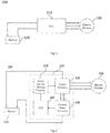
- Figure 1 illustrates a schematic view of a system 100 for controlling an electric machine 130 to achieve a desired cranking of an internal combustion engine in accordance with an embodiment of the invention.
- the permanent magnet machine includes a rotor having a plurality of permanent magnets poles, and a stator having a plurality of phase windings disposed on the stator, each phase winding including a plurality of coils,
- a control unit 110 is connected to a power supply 120 and the electric motor 130.
- the control unit may be a dedicated or an onboard Electronic Control Unit (ECU) of a vehicle.
- the power supply may be a battery of the vehicle.
- the ECU Based on various inputs in the form of voltage, current, speed of the electric motor, etc, received by the ECU, the ECU determines position of the rotor and further provides requisite signal to excite the relevant stator windings based on the rotor position.
- FIG. 2 illustrates architecture of the control unit in accordance with an embodiment of the invention.
- the ECU comprises a set of power switches 220 used to selectively connect battery terminals to motor terminals.
- the power switches are driven by a control circuit or a power switch driving circuit 210.
- a current sensing circuit 230 converts the current flowing through the electric machine or through battery in a form that can be read by a central processing unit (CPU) 240.
- CPU central processing unit
- the CPU determines position of the rotor and sends commands to control circuit, which actuates appropriate power switches to connect selected terminals of motor to battery terminals.
- FIG. 3 shows a flowchart illustrating steps taken to control an integrated starter-generator in accordance with an embodiment of the invention.
- the CPU checks if a start command is received. If no start command is received, the CPU remains in step 3A. If a start command is received, in step 3B, the CPU determines an initial position of the rotor with respect to a stator phase winding.
- CPU For determination of initial position of the rotor with respect to a stator phase winding, CPU selects a pair of stator phase windings and a voltage signal is applied across the selected pair of stator phase windings for a predetermined period of time. Current measurement is carried for each of the selected windings. Initial position of the rotor is determined based on the pair of stator phase windings for which the measured current is maximum.
- the CPU applies a pulse-width-modulated (PWM) signal to the stator winding corresponding to determined initial position of the rotor.
- PWM pulse-width-modulated
- FIG 4 depicts an equivalent circuit of the electric machine as seen from active motor terminals when a specific stator excitation is applied.
- a specific stator excitation When a specific stator excitation is applied, a magnetic field is built within the stator.
- the inductance of the machine as seen from the active motor terminals is a function of rotor position as described in figure 5 .
- the stator material As the rotor magnetic field aligns with the stator excitation magnetic field, the stator material enters magnetic saturation. Since inductance is proportional to the slope of the BH curve, the inductance as seen from the active motor terminals decreases. This change in inductance as a function of rotor position and as a function of stator excitation is leveraged to detect initial rotor position and to update stator excitation as the rotor moves during motoring action.
- Figure 6 is a graphical representation of results obtained while determining an initial position of a rotor in accordance with an embodiment of the invention. It shows result of a typical initial position estimation procedure, which shows the current detected by current measurement circuit for a set of commands for two different rotor positions. As seen from the figure, the current detected by the current measurement circuit for all commands is not same. The current detected corresponding to one command is substantially more than others. The command corresponding to which the current is more is different for different rotor positions. Thus, by observing the command for which the detected current is maximum, it is possible to determine the rotor position.
- the CPU determines threshold value of stator current variation.
- instantaneous or average battery voltage is measured along with instantaneous or average engine speed. Thereafter, stator current is measured substantially at the beginning of PWM cycle and substantially at the end of PWM cycle. Based on these measurements, the threshold value is determined.
- the CPU measures current of the stator winding in response to applied PWM signal to determine current variation.
- current variation is compared with the threshold value determined in step 3D. In case the current variation is more than the threshold value, updated rotor position is determined at step 3G and a PWM signal is applied to the stator winding corresponding to the updated rotor position. In case the current variation is less than the threshold value, PWM signal is applied, at step 3H, to the stator winding corresponding to the last updated position of the rotor and current of the stator winding in response to applied PWM signal is measured to determine current variation.
- Figure 7 is a graphical representation of current variation and commutation based on current variation in accordance with an embodiment of the invention.
- a PWM control sequence consists of an on-time, when the chosen motor terminal is connected to the battery terminals and an off-time, where the current in motor terminals is allowed to recirculate through the power switches.
- the output of the current measurement circuit rises, while during the off-time, the output of the current measurement circuit falls due to energy lost in resistance of motor windings and in power switches.
- the extent of the rise and fall during the PWM operation is a function of inductance of the electric machine. Higher inductance leads to higher resistance to change in current, leading to lower extent of rise and fall, while a lower inductance leads to lower resistance to change in current, leading to higher extent of rise and fall.
- the inductance of the machine is a function of rotor position.
- the inductance of the machine changes periodically.
- This change in inductance leads to change in extent of current rise and fall.
- figure 8 shows a relation between current ripple and time to determine the change in commutation. Change in commutation takes place when ripple current crosses a threshold value.
- the CPU determines the speed of the engine. In case it is determined that speed of the engine is more than a threshold value then the method is terminated. However, in case it is determined that speed of the engine is less than a threshold value then current variation in the stator winding is determined to update the excitation of the stator winding.
Landscapes
- Engineering & Computer Science (AREA)
- Power Engineering (AREA)
- Chemical & Material Sciences (AREA)
- Combustion & Propulsion (AREA)
- Mechanical Engineering (AREA)
- General Engineering & Computer Science (AREA)
- Control Of Motors That Do Not Use Commutators (AREA)
- Combined Controls Of Internal Combustion Engines (AREA)
- Hybrid Electric Vehicles (AREA)
- Motor And Converter Starters (AREA)
- Control Of Eletrric Generators (AREA)
Description
- The invention relates to cranking an internal combustion engine and more particularly to method and system for cranking an internal combustion engine coupled to a permanent magnet machine.
- An Integrated Starter Generator (ISG) system is generally used for the purpose of starting an Internal Combustion (IC) engine and for electric power generation. Typically an ISG system has a single electric machine connected to a crankshaft of a vehicle. For starting of IC engine, the electric machine is rotated which in turn rotates the crankshaft. Such rotation should be at a sufficiently high speed before the self-sustaining combustion process can commence inside the IC engine. During a power generation operation, crankshaft rotates the electric machine to generate electric power required to charge a battery and power other electrical loads of the vehicle.
- In a conventional ISG system, an electronic control unit (ECU) is placed between a battery and an electric machine of a vehicle where the ECU regulates bidirectional flow of electric power between the battery and electric machine. During engine start operation, the ECU draws power from the battery and feeds it to drive the electric machine, whereas during power generation operation, it regulates flow of electric power from the electric machine to charge the battery and also supply power to other electrical loads.
- Most ISG systems use a permanent magnet brushless electric machine (BLDC machine). Such machines consist of a stator made of a polyphase winding, and a rotor made of permanent magnets. For optimal operation of ISG system, the ECU needs to excite the stator windings in a particular sequence with respect to the position of the rotor of the electric machine. In this regard, multiple hall-effect based sensors are typically used for sensing rotor position. Such sensors are placed either inside the stator windings or a separate magnetic ring is used to trigger the hall-effect based sensors. In either case, the sensors are needed to be placed inside a casing of the IC engine. An alternative to hall-effect based sensors is to use an absolute angle sensor of the crankshaft. However, such sensor also needs to be placed inside the engine casing.
- Since such sensors are placed inside engine casing, they are subjected to harsh operating conditions such as high temperature and vibrations, which make them prone to failure. Further, a special arrangement is required for mounting the sensors which adds cost and occupies space inside the engine casing. Furthermore, the sensors need to be connected to ECU using wires for providing signals from the sensors to the ECU. For this purpose, a provision for routing of wires from sensors to ECU is also required. Further, any damage to wires impairs operation of the ISG system.
- In view of the above there exists a need in the art to at least address the above mentioned problems.
-
CN105162374A discloses a starting control method of a brushless direct-current motor comprising the following steps: (S1) detecting a current position of a rotor; (S2) outputting a pulse width modulation signal of which the duty ratio is a first threshold according to the current position of the rotor to drive the brushless direct-current motor; (S3) judging whether currently detected current is greater than a preset value, if so, executing the step (S4), or else, executing the step (S5); (S4) lowering the pulse width modulation signal and restarting the brushless direct-current motor; (S5) judging whether the brushless direct-current motor rotates or not, if so, executing the step (S6), or else, executing the step (S7); (S6) exiting starting, and feeding back a starting success signal; (S7) when the duration that the brushless direct-current motor is driven with the pulse width modulation signal with the same duty ratio is greater than first preset time, controlling the duty ratio of the pulse width modulation signal to increase a second threshold, so as to drive the pulse width modulation signal again. -
US2010225262A1 discloses a method for determining the position of a rotor in a permanent magnet synchronous motor which includes applying voltage pulses to the windings at successive electrical angles while the motor is at a standstill. The resultant current is sampled. The position of a maximum current is determined by identifying a segment of an electrical cycle which includes the maximum current, and using a spline interpolation to model the current flow in this segment. The maximum current is then correlated to the position of the rotor. - Accordingly, the present invention in one aspect provides a method for cranking an internal combustion engine coupled to a permanent magnet machine. The permanent magnet machine comprising a rotor having a plurality of permanent magnets poles, and a stator having a plurality of phase windings disposed on the stator, each phase winding including a plurality of coils. The method comprising the steps of: (a) receiving a start signal; (b) determining an initial position of the rotor with respect to a stator phase winding; (c) applying a pulse-width-modulated signal to the stator winding corresponding to determined initial position of the rotor; (d) determining a threshold value of the stator current variation; (e) measuring current of the stator winding in response to applied pulse-width-modulated signal to determine current variation; (f) if current variation is more than the threshold value: determining updated rotor position, applying a pulse-width-modulated signal to the stator winding corresponding to the updated rotor position; and repeating steps (d) - (f); and (g) if current variation is less than the threshold value: applying a pulse-width-modulated signal to the stator winding corresponding to the last updated rotor position and repeating steps (d) - (g).
- In another aspect, the present invention provides a system for cranking an internal combustion engine coupled to a permanent magnet machine. The permanent magnet machine comprising a rotor having a plurality of permanent magnets poles, and a stator having a plurality of phase windings disposed on the stator, each phase winding including a plurality of coils. The system comprising: a control unit coupled to permanent magnet machine and a power supply connected to the control unit. The control unit is configured to: (a) receive a start signal; (b) determine an initial position of the rotor with respect to a stator phase winding; (c) apply a pulse-width-modulated signal to the stator winding corresponding to determined initial position of the rotor; (d) determine a threshold value of the stator current variation; (e) measure current of the stator winding in response to applied pulse-width-modulated signal to determine current variation; (f) if current variation is more than the threshold value: determine updated rotor position, apply a pulse-width-modulated signal to the stator winding corresponding to the updated rotor position; and repeat steps (d) - (f); and (g) if current variation is less than the threshold value: apply a pulse-width-modulated signal to the stator winding corresponding to the last updated rotor position and repeat steps (d) - (g).
- Reference will be made to embodiments of the invention, examples of which may be illustrated in accompanying figures. These figures are intended to be illustrative, not limiting. Although the invention is generally described in context of these embodiments, it should be understood that it is not intended to limit the scope of the invention to these particular embodiments.
-
Figure 1 illustrates a schematic view of a system for cranking an internal combustion engine in accordance with an embodiment of the invention. -
Figure 2 illustrates architecture of a control unit in accordance with an embodiment of the invention. -
Figure 3 shows a flowchart illustrating steps taken for cranking an internal combustion engine in accordance with an embodiment of the invention. -
Figure 4 shows an equivalent circuit of an electric machine as seen from active terminals of a motor. -
Figure 5 shows relation between the inductance of a machine and position of the rotor. -
Figure 6 is a graphical representation of results obtained while determining an initial position of a rotor in accordance with an embodiment of the invention. -
Figure 7 is a graphical representation current variation and commutation based on current variation in accordance with an embodiment of the invention. -
Figure 8 shows a relation between current ripple and time to determine the change in commutation. - The present invention is directed to a method and a system for cranking an internal combustion engine coupled to a permanent magnet machine.
-
Figure 1 illustrates a schematic view of asystem 100 for controlling anelectric machine 130 to achieve a desired cranking of an internal combustion engine in accordance with an embodiment of the invention. The permanent magnet machine includes a rotor having a plurality of permanent magnets poles, and a stator having a plurality of phase windings disposed on the stator, each phase winding including a plurality of coils, - As shown, a
control unit 110 is connected to apower supply 120 and theelectric motor 130. In this regard, the control unit may be a dedicated or an onboard Electronic Control Unit (ECU) of a vehicle. The power supply may be a battery of the vehicle. - Based on various inputs in the form of voltage, current, speed of the electric motor, etc, received by the ECU, the ECU determines position of the rotor and further provides requisite signal to excite the relevant stator windings based on the rotor position.
-
Figure 2 illustrates architecture of the control unit in accordance with an embodiment of the invention. The ECU comprises a set ofpower switches 220 used to selectively connect battery terminals to motor terminals. The power switches are driven by a control circuit or a powerswitch driving circuit 210. Acurrent sensing circuit 230 converts the current flowing through the electric machine or through battery in a form that can be read by a central processing unit (CPU) 240. - Based on inputs received from current sensing circuit and other parameters, the CPU determines position of the rotor and sends commands to control circuit, which actuates appropriate power switches to connect selected terminals of motor to battery terminals.
-
Figure 3 shows a flowchart illustrating steps taken to control an integrated starter-generator in accordance with an embodiment of the invention. Atstep 3A, the CPU checks if a start command is received. If no start command is received, the CPU remains instep 3A. If a start command is received, instep 3B, the CPU determines an initial position of the rotor with respect to a stator phase winding. - For determination of initial position of the rotor with respect to a stator phase winding, CPU selects a pair of stator phase windings and a voltage signal is applied across the selected pair of stator phase windings for a predetermined period of time. Current measurement is carried for each of the selected windings. Initial position of the rotor is determined based on the pair of stator phase windings for which the measured current is maximum. At
step 3C, the CPU applies a pulse-width-modulated (PWM) signal to the stator winding corresponding to determined initial position of the rotor. - Referring to
figure 4 which depicts an equivalent circuit of the electric machine as seen from active motor terminals when a specific stator excitation is applied. When a specific stator excitation is applied, a magnetic field is built within the stator. For a given stator excitation with a given amount of stator current, the inductance of the machine as seen from the active motor terminals is a function of rotor position as described infigure 5 . As the rotor magnetic field aligns with the stator excitation magnetic field, the stator material enters magnetic saturation. Since inductance is proportional to the slope of the BH curve, the inductance as seen from the active motor terminals decreases. This change in inductance as a function of rotor position and as a function of stator excitation is leveraged to detect initial rotor position and to update stator excitation as the rotor moves during motoring action. -
Figure 6 is a graphical representation of results obtained while determining an initial position of a rotor in accordance with an embodiment of the invention. It shows result of a typical initial position estimation procedure, which shows the current detected by current measurement circuit for a set of commands for two different rotor positions. As seen from the figure, the current detected by the current measurement circuit for all commands is not same. The current detected corresponding to one command is substantially more than others. The command corresponding to which the current is more is different for different rotor positions. Thus, by observing the command for which the detected current is maximum, it is possible to determine the rotor position. - At
step 3D, the CPU determines threshold value of stator current variation. In this regard, instantaneous or average battery voltage is measured along with instantaneous or average engine speed. Thereafter, stator current is measured substantially at the beginning of PWM cycle and substantially at the end of PWM cycle. Based on these measurements, the threshold value is determined. - At
step 3E, the CPU measures current of the stator winding in response to applied PWM signal to determine current variation. Atstep 3F, current variation is compared with the threshold value determined instep 3D. In case the current variation is more than the threshold value, updated rotor position is determined atstep 3G and a PWM signal is applied to the stator winding corresponding to the updated rotor position. In case the current variation is less than the threshold value, PWM signal is applied, atstep 3H, to the stator winding corresponding to the last updated position of the rotor and current of the stator winding in response to applied PWM signal is measured to determine current variation.
Figure 7 is a graphical representation of current variation and commutation based on current variation in accordance with an embodiment of the invention. A PWM control sequence consists of an on-time, when the chosen motor terminal is connected to the battery terminals and an off-time, where the current in motor terminals is allowed to recirculate through the power switches. As shown in the figure, during the on-time of the PWM control, the output of the current measurement circuit rises, while during the off-time, the output of the current measurement circuit falls due to energy lost in resistance of motor windings and in power switches. The extent of the rise and fall during the PWM operation is a function of inductance of the electric machine. Higher inductance leads to higher resistance to change in current, leading to lower extent of rise and fall, while a lower inductance leads to lower resistance to change in current, leading to higher extent of rise and fall. Moreover, as described hereinbefore, the inductance of the machine is a function of rotor position. Thus, as the electric machine runs, its rotor position and hence the inductance changes periodically. This change in inductance leads to change in extent of current rise and fall. Thus, by observing this extent in rise and fall of current, it is possible to determine when the excitation sequence needs to change. In this regard,figure 8 shows a relation between current ripple and time to determine the change in commutation. Change in commutation takes place when ripple current crosses a threshold value. - In an embodiment of the invention, after
step - Advantageously, using the ECU architecture described hereinbefore, it is possible to carry out cranking of an internal combustion engine without any sensor.
- While the present invention has been described with respect to certain embodiments, it will be apparent to those skilled in the art that various changes and modification may be made without departing from the scope of the invention as defined in the following claims.
Claims (4)
- A method for cranking an internal combustion engine, the engine coupled to a permanent magnet machine comprising a rotor having a plurality of permanent magnets poles, and a stator having a plurality of phase windings disposed on the stator, each phase winding including a plurality of coils, the method comprising the steps of:(a) receiving a start signal;(b) determining an initial position of the rotor with respect to a stator phase winding;(c) applying a pulse-width-modulated PWM signal to the stator winding corresponding to determined initial position of the rotor; characterised by(d) determining a threshold value of the stator current variation;(e) measuring current of the stator winding in response to applied pulse-width-modulated signal to determine current variation;(f) if current variation is more than the threshold value: determining updated rotor position, applying a pulse-width-modulated signal to the stator winding corresponding to the updated rotor position; and repeating steps (d) - (f); and(g) if current variation is less than the threshold value: applying a pulse-width-modulated signal to the stator winding corresponding to the last updated rotor position and repeating steps (d) - (g).
- The method for cranking an internal combustion engine as claimed in claim 1 wherein step of determining a threshold value of the stator current variation comprises:measuring instantaneous or average battery voltage;measuring instantaneous or average engine speed;measuring stator current substantially at the beginning of PWM cycle and substantially at the end of PWM cycle; and determining the threshold value based on the measured battery voltage, engine speed and stator current.
- The method for controlling an integrated starter- generator as claimed in claim 1 or 2, wherein the step of determining an initial position of the rotor with respect to a stator phase winding comprises:(a) selecting a pair of stator phase windings;(b) applying a voltage signal across the selected pair of stator phase windings for a predetermined period of time;(c) measuring the current flowing through the selected windings;(d) repeating steps (a) - (c) for a newly selected pair of stator phase windings; and(e) determining position of the rotor based on the pair of stator phase windings for which the measured current is maximum.
- A system (100) for cranking an internal combustion engine, the engine coupled to a permanent magnet machine (130) comprising a rotor having a plurality of permanent magnets poles, and a stator having a plurality of phase windings disposed on the stator, each phase winding including a plurality of coils, the system comprising:a control unit (110) coupled to the permanent magnet machine (130) and configured to:(a) receive a start signal;(b) determine an initial position of the rotor with respect to a stator phase winding;(c) apply a pulse-width-modulated signal to the stator winding corresponding to determined initial position of the rotor;(d) determine a threshold value of the stator current variation;(e) measure current of the stator winding in response to applied pulse-width-modulated signal to determine current variation;(f) if current variation is more than the threshold value: determine updated rotor position, apply a pulse-width-modulated signal to the stator winding corresponding to the updated rotor position; and repeat steps (d) - (f); and(g) if current variation is less than the threshold value: apply a pulse-width-modulated signal to the stator winding corresponding to the last updated rotor position and repeat steps (d) - (g); anda power supply (120) connected to the control unit (110).
Applications Claiming Priority (3)
| Application Number | Priority Date | Filing Date | Title |
|---|---|---|---|
| IN201621004628 | 2016-02-11 | ||
| IN201621040030 | 2016-11-23 | ||
| PCT/IN2017/000036 WO2017138020A2 (en) | 2016-02-11 | 2017-02-13 | Method and system for cranking an internal combustion engine |
Publications (3)
| Publication Number | Publication Date |
|---|---|
| EP3414449A2 EP3414449A2 (en) | 2018-12-19 |
| EP3414449A4 EP3414449A4 (en) | 2019-08-14 |
| EP3414449B1 true EP3414449B1 (en) | 2021-03-31 |
Family
ID=59563070
Family Applications (1)
| Application Number | Title | Priority Date | Filing Date |
|---|---|---|---|
| EP17750000.6A Active EP3414449B1 (en) | 2016-02-11 | 2017-02-13 | Method and system for cranking an internal combustion engine |
Country Status (5)
| Country | Link |
|---|---|
| US (1) | US11349418B2 (en) |
| EP (1) | EP3414449B1 (en) |
| JP (1) | JP7231199B2 (en) |
| CN (1) | CN109072854B (en) |
| WO (1) | WO2017138020A2 (en) |
Families Citing this family (1)
| Publication number | Priority date | Publication date | Assignee | Title |
|---|---|---|---|---|
| KR20240030597A (en) * | 2022-08-31 | 2024-03-07 | 주식회사 엘엑스세미콘 | Motor driver, motor drive system and method for driving motor |
Family Cites Families (48)
| Publication number | Priority date | Publication date | Assignee | Title |
|---|---|---|---|---|
| US4364004A (en) * | 1980-01-29 | 1982-12-14 | Bourbeau Frank J | Self-controlled polyphase synchronous motor drive system |
| US5468188A (en) * | 1992-10-02 | 1995-11-21 | Day; Stanley J. | Universal coupling |
| US5627444A (en) * | 1995-05-30 | 1997-05-06 | General Motors Corporation | Switched reluctance motor control |
| US5600218A (en) * | 1995-09-11 | 1997-02-04 | George H. Holling | Sensorless commutation position detection for brushless motors |
| US5821713A (en) * | 1995-09-11 | 1998-10-13 | Advanced Motion Controls, Inc. | Commutation position detection system and method |
| US6023137A (en) | 1997-10-01 | 2000-02-08 | General Electric Company | Use of traction inverter for supplying power for non-traction applications |
| US5998946A (en) * | 1997-10-08 | 1999-12-07 | Daewoo Electronics Co., Ltd. | Method and apparatus for controlling a rotation of a sensorless and brushless DC motor |
| WO2001045247A1 (en) * | 1999-12-14 | 2001-06-21 | The Penn State Research Foundation | Detection of rotor angle in a permanent magnet synchronous motor at zero speed |
| JP4046266B2 (en) * | 2001-12-11 | 2008-02-13 | 本田技研工業株式会社 | Starting method of brushless rotating electrical machine for driving internal combustion engine |
| US7153227B2 (en) * | 2002-04-18 | 2006-12-26 | Litens Automotive | Isolator for alternator pulley |
| ES2298586T3 (en) * | 2002-07-26 | 2008-05-16 | Litens Automotive | ALTERNATOR DECOUPLER FREE WHEEL PULLEY WITH A NUDE WIRE SPRING AND FAT LUBRICATION. |
| CA2759773C (en) * | 2002-11-22 | 2013-05-28 | Litens Automotive | Flexible coupling with misalignment compensation |
| CN1416205A (en) * | 2002-12-14 | 2003-05-07 | 伍本银 | Two-in-one permanent magnet brushless electomotor with internal rotor |
| JP2007517168A (en) * | 2003-12-09 | 2007-06-28 | ライテンズ オートモーティブ パートナーシップ | Spring travel limiter for overrun of alternator decoupler |
| JP4386815B2 (en) * | 2004-10-04 | 2009-12-16 | パナソニック株式会社 | Motor driving apparatus and driving method |
| US7211984B2 (en) * | 2004-11-09 | 2007-05-01 | General Motors Corporation | Start-up and restart of interior permanent magnet machines |
| JP4350676B2 (en) * | 2005-03-31 | 2009-10-21 | 本田技研工業株式会社 | Control device for hybrid vehicle |
| US7334854B1 (en) * | 2006-09-20 | 2008-02-26 | Aimtron Technology Corp. | Sensorless start-up method for driving a brushless DC motor |
| US9160264B2 (en) * | 2007-11-16 | 2015-10-13 | Hamilton Sundstrand Corporation | Initial rotor position detection and start-up system for a dynamoelectric machine |
| JP4508237B2 (en) * | 2007-12-19 | 2010-07-21 | 株式会社デンソー | Rotating machine control device |
| US8312590B2 (en) * | 2008-10-06 | 2012-11-20 | Shop Vac Corporation | System and method of controlling start-up of a switched reluctance motor |
| KR101724756B1 (en) * | 2008-10-27 | 2017-04-07 | 리텐스 오토모티브 파트너쉽 | Over-running decoupler with torque limiter |
| PL2347143T3 (en) * | 2008-11-17 | 2015-06-30 | Litens Automotive Inc | A helical coil clutch assembly comprising an actuator to effect engagement of helical coil clutch with a clutch surface |
| US7969108B2 (en) * | 2008-12-03 | 2011-06-28 | Semiconductor Components Industries, Llc | Control circuit for a brushless DC motor and method therefor |
| US8030788B2 (en) * | 2008-12-31 | 2011-10-04 | General Electric Company | Method and systems for an engine starter/generator |
| BRPI1006833B1 (en) * | 2009-01-14 | 2020-10-20 | Panasonic Corporation | motor drive device |
| TWI382650B (en) * | 2009-01-22 | 2013-01-11 | Richtek Techohnology Corp | Apparatus and method for detecting rotor position of pmsm |
| US8324851B2 (en) | 2009-03-04 | 2012-12-04 | Rockwell Automation Technologies, Inc. | Method for determining a rotor position in a permanent magnet motor |
| JP4799652B2 (en) * | 2009-09-03 | 2011-10-26 | 三菱電機株式会社 | Idling stop restart control system |
| US8704479B2 (en) * | 2009-11-11 | 2014-04-22 | Stmicroelectronics, Inc. | System and method for determining the start position of a motor |
| KR101009177B1 (en) * | 2010-01-29 | 2011-01-18 | 삼성전기주식회사 | Sensorless Brushless DC Motor |
| BRPI1101069A2 (en) * | 2011-03-01 | 2013-06-04 | Whirlpool Sa | Starting method for single-phase induction motor, single-phase motor starting device and starter system |
| CN102198805B (en) * | 2011-03-09 | 2016-09-28 | 王子辉 | A kind of pure electric automobile ramp method in slope that magneto drives |
| JP5838038B2 (en) * | 2011-04-22 | 2015-12-24 | サンデンホールディングス株式会社 | Motor control device |
| JP5888879B2 (en) * | 2011-06-02 | 2016-03-22 | 株式会社ミツバ | Drive device and stop position detection method |
| US9515588B2 (en) * | 2012-03-06 | 2016-12-06 | Dyson Technology Limited | Sensorless control of a brushless permanent-magnet motor |
| US8994306B2 (en) * | 2012-05-25 | 2015-03-31 | Cirrus Logic, Inc. | System and method for isolating the undriven voltage of a permanent magnet brushless motor for detection of rotor position |
| US9638270B2 (en) * | 2012-08-07 | 2017-05-02 | Litens Automotive Partnership | Decoupler carrier with balanced forces |
| US9140319B2 (en) * | 2012-11-20 | 2015-09-22 | Litens Automotive Partnership | Decoupler with concentric clutching members |
| US9651099B2 (en) * | 2013-01-25 | 2017-05-16 | Litens Automotive Partnership | Clutched device with wrap spring clutch with overrun locking member |
| WO2014180804A2 (en) * | 2013-05-07 | 2014-11-13 | Sanofi-Aventis Deutschland Gmbh | Apparatus employing coil inductance determination and method for operating the apparatus |
| EP3690271A1 (en) * | 2013-08-27 | 2020-08-05 | Litens Automotive Partnership | Isolator for use with engine that is assisted or started by an motor-generator unit (mgu) or a motor through an endless drive member |
| EP3230610A4 (en) * | 2014-12-09 | 2018-07-18 | Litens Automotive Partnership | Isolator for use with engine that is assisted or started by an mgu or a motor through an endless drive member |
| DE102015211863B4 (en) * | 2015-06-25 | 2026-01-29 | Lenze Se | Method for determining current-dependent and/or angle-dependent parameters of an electrical machine and frequency converter |
| CN105162374B (en) | 2015-08-27 | 2018-05-01 | 深圳市沛城电子科技有限公司 | The startup control method and device of brshless DC motor |
| CN107960145B (en) * | 2015-08-28 | 2020-11-03 | 松下知识产权经营株式会社 | Motor drive device, and drive device for compressor and refrigerator using same |
| CN105245159A (en) * | 2015-09-08 | 2016-01-13 | 江苏大学 | Direct torque control method of five-phase permanent magnet fault-tolerant motor based on new pulse width modulation |
| KR20190006227A (en) * | 2017-07-10 | 2019-01-18 | 현대자동차주식회사 | Decoupler |
-
2017
- 2017-02-13 EP EP17750000.6A patent/EP3414449B1/en active Active
- 2017-02-13 JP JP2018561109A patent/JP7231199B2/en active Active
- 2017-02-13 CN CN201780011204.7A patent/CN109072854B/en active Active
- 2017-02-13 WO PCT/IN2017/000036 patent/WO2017138020A2/en not_active Ceased
- 2017-02-13 US US16/077,156 patent/US11349418B2/en active Active
Non-Patent Citations (1)
| Title |
|---|
| None * |
Also Published As
| Publication number | Publication date |
|---|---|
| EP3414449A4 (en) | 2019-08-14 |
| JP7231199B2 (en) | 2023-03-01 |
| WO2017138020A3 (en) | 2017-11-09 |
| JP2019511675A (en) | 2019-04-25 |
| US20210211077A1 (en) | 2021-07-08 |
| CN109072854A (en) | 2018-12-21 |
| US11349418B2 (en) | 2022-05-31 |
| CN109072854B (en) | 2021-12-14 |
| EP3414449A2 (en) | 2018-12-19 |
| WO2017138020A2 (en) | 2017-08-17 |
Similar Documents
| Publication | Publication Date | Title |
|---|---|---|
| CN101127502B (en) | Brushless motor driving device, brushless motor starting method, and method of detecting rotor stop position of brushless motor | |
| JP4596185B2 (en) | Voltage control device for vehicle | |
| CN102545755B (en) | Controller for controlling power generator driven by rotational power of engine | |
| CN111030548B (en) | Reliable control of multi-rotor pole switched reluctance motor | |
| CN103563240A (en) | Method for determining current in a polyphase machine | |
| JP2014204451A (en) | Controller of vehicular generator motor and method thereof | |
| US9614397B2 (en) | Battery charging apparatus for vehicle | |
| EP3414450B1 (en) | Method and system for controlling an integrated starter-generator | |
| US9685893B2 (en) | Alternating current generation system accompanying power conversion | |
| US9000704B2 (en) | Three-phase motor driving apparatus and three-phase motor driving method | |
| CN110870196B (en) | New pulse injection current pattern for rotor position estimation | |
| CN109818537A (en) | A method for identifying the initial conduction phase of a switched reluctance motor without a position sensor | |
| US11349418B2 (en) | Method and system for cranking an internal combustion engine | |
| CN103684122B (en) | The control method and device of switched reluctance machines | |
| US20190280631A1 (en) | Method and circuit arrangement for determining the position of a rotor in an electric motor | |
| JP5709464B2 (en) | Motor drive control device | |
| JP6643968B2 (en) | SR motor control system and SR motor control method | |
| CN111434025B (en) | Method for determining the rotor angle of an electric machine in a motor vehicle | |
| JP6967880B2 (en) | Electronic control device | |
| JP6948845B2 (en) | Electronic control device | |
| JP2018085896A (en) | Abnormality detection device of rotation sensor | |
| CN121710745A (en) | Starting and power generation integrated control method based on permanent magnet motor outer distribution boss | |
| KR20060115121A (en) | Low Voltage Sensorless Motor Structure |
Legal Events
| Date | Code | Title | Description |
|---|---|---|---|
| STAA | Information on the status of an ep patent application or granted ep patent |
Free format text: STATUS: THE INTERNATIONAL PUBLICATION HAS BEEN MADE |
|
| PUAI | Public reference made under article 153(3) epc to a published international application that has entered the european phase |
Free format text: ORIGINAL CODE: 0009012 |
|
| STAA | Information on the status of an ep patent application or granted ep patent |
Free format text: STATUS: REQUEST FOR EXAMINATION WAS MADE |
|
| 17P | Request for examination filed |
Effective date: 20180910 |
|
| AK | Designated contracting states |
Kind code of ref document: A2 Designated state(s): AL AT BE BG CH CY CZ DE DK EE ES FI FR GB GR HR HU IE IS IT LI LT LU LV MC MK MT NL NO PL PT RO RS SE SI SK SM TR |
|
| AX | Request for extension of the european patent |
Extension state: BA ME |
|
| DAV | Request for validation of the european patent (deleted) | ||
| DAX | Request for extension of the european patent (deleted) | ||
| A4 | Supplementary search report drawn up and despatched |
Effective date: 20190716 |
|
| RIC1 | Information provided on ipc code assigned before grant |
Ipc: F02N 11/00 20060101ALI20190710BHEP Ipc: F02N 15/02 20060101ALI20190710BHEP Ipc: F02N 11/04 20060101AFI20190710BHEP Ipc: H02P 9/08 20060101ALI20190710BHEP Ipc: F02N 11/02 20060101ALI20190710BHEP Ipc: F02D 29/06 20060101ALI20190710BHEP Ipc: F02N 11/08 20060101ALI20190710BHEP Ipc: H02P 6/20 20160101ALI20190710BHEP |
|
| GRAP | Despatch of communication of intention to grant a patent |
Free format text: ORIGINAL CODE: EPIDOSNIGR1 |
|
| STAA | Information on the status of an ep patent application or granted ep patent |
Free format text: STATUS: GRANT OF PATENT IS INTENDED |
|
| INTG | Intention to grant announced |
Effective date: 20200925 |
|
| GRAS | Grant fee paid |
Free format text: ORIGINAL CODE: EPIDOSNIGR3 |
|
| RAP1 | Party data changed (applicant data changed or rights of an application transferred) |
Owner name: SEDEMAC MECHATRONICS PVT LTD |
|
| GRAA | (expected) grant |
Free format text: ORIGINAL CODE: 0009210 |
|
| STAA | Information on the status of an ep patent application or granted ep patent |
Free format text: STATUS: THE PATENT HAS BEEN GRANTED |
|
| AK | Designated contracting states |
Kind code of ref document: B1 Designated state(s): AL AT BE BG CH CY CZ DE DK EE ES FI FR GB GR HR HU IE IS IT LI LT LU LV MC MK MT NL NO PL PT RO RS SE SI SK SM TR |
|
| REG | Reference to a national code |
Ref country code: GB Ref legal event code: FG4D Ref country code: CH Ref legal event code: EP |
|
| REG | Reference to a national code |
Ref country code: AT Ref legal event code: REF Ref document number: 1377211 Country of ref document: AT Kind code of ref document: T Effective date: 20210415 |
|
| REG | Reference to a national code |
Ref country code: DE Ref legal event code: R096 Ref document number: 602017035713 Country of ref document: DE |
|
| REG | Reference to a national code |
Ref country code: IE Ref legal event code: FG4D |
|
| REG | Reference to a national code |
Ref country code: LT Ref legal event code: MG9D |
|
| PG25 | Lapsed in a contracting state [announced via postgrant information from national office to epo] |
Ref country code: NO Free format text: LAPSE BECAUSE OF FAILURE TO SUBMIT A TRANSLATION OF THE DESCRIPTION OR TO PAY THE FEE WITHIN THE PRESCRIBED TIME-LIMIT Effective date: 20210630 Ref country code: FI Free format text: LAPSE BECAUSE OF FAILURE TO SUBMIT A TRANSLATION OF THE DESCRIPTION OR TO PAY THE FEE WITHIN THE PRESCRIBED TIME-LIMIT Effective date: 20210331 Ref country code: HR Free format text: LAPSE BECAUSE OF FAILURE TO SUBMIT A TRANSLATION OF THE DESCRIPTION OR TO PAY THE FEE WITHIN THE PRESCRIBED TIME-LIMIT Effective date: 20210331 Ref country code: BG Free format text: LAPSE BECAUSE OF FAILURE TO SUBMIT A TRANSLATION OF THE DESCRIPTION OR TO PAY THE FEE WITHIN THE PRESCRIBED TIME-LIMIT Effective date: 20210630 |
|
| PG25 | Lapsed in a contracting state [announced via postgrant information from national office to epo] |
Ref country code: RS Free format text: LAPSE BECAUSE OF FAILURE TO SUBMIT A TRANSLATION OF THE DESCRIPTION OR TO PAY THE FEE WITHIN THE PRESCRIBED TIME-LIMIT Effective date: 20210331 Ref country code: LV Free format text: LAPSE BECAUSE OF FAILURE TO SUBMIT A TRANSLATION OF THE DESCRIPTION OR TO PAY THE FEE WITHIN THE PRESCRIBED TIME-LIMIT Effective date: 20210331 Ref country code: SE Free format text: LAPSE BECAUSE OF FAILURE TO SUBMIT A TRANSLATION OF THE DESCRIPTION OR TO PAY THE FEE WITHIN THE PRESCRIBED TIME-LIMIT Effective date: 20210331 |
|
| REG | Reference to a national code |
Ref country code: NL Ref legal event code: MP Effective date: 20210331 |
|
| REG | Reference to a national code |
Ref country code: AT Ref legal event code: MK05 Ref document number: 1377211 Country of ref document: AT Kind code of ref document: T Effective date: 20210331 |
|
| PG25 | Lapsed in a contracting state [announced via postgrant information from national office to epo] |
Ref country code: EE Free format text: LAPSE BECAUSE OF FAILURE TO SUBMIT A TRANSLATION OF THE DESCRIPTION OR TO PAY THE FEE WITHIN THE PRESCRIBED TIME-LIMIT Effective date: 20210331 Ref country code: CZ Free format text: LAPSE BECAUSE OF FAILURE TO SUBMIT A TRANSLATION OF THE DESCRIPTION OR TO PAY THE FEE WITHIN THE PRESCRIBED TIME-LIMIT Effective date: 20210331 Ref country code: LT Free format text: LAPSE BECAUSE OF FAILURE TO SUBMIT A TRANSLATION OF THE DESCRIPTION OR TO PAY THE FEE WITHIN THE PRESCRIBED TIME-LIMIT Effective date: 20210331 Ref country code: NL Free format text: LAPSE BECAUSE OF FAILURE TO SUBMIT A TRANSLATION OF THE DESCRIPTION OR TO PAY THE FEE WITHIN THE PRESCRIBED TIME-LIMIT Effective date: 20210331 Ref country code: SM Free format text: LAPSE BECAUSE OF FAILURE TO SUBMIT A TRANSLATION OF THE DESCRIPTION OR TO PAY THE FEE WITHIN THE PRESCRIBED TIME-LIMIT Effective date: 20210331 Ref country code: AT Free format text: LAPSE BECAUSE OF FAILURE TO SUBMIT A TRANSLATION OF THE DESCRIPTION OR TO PAY THE FEE WITHIN THE PRESCRIBED TIME-LIMIT Effective date: 20210331 |
|
| PG25 | Lapsed in a contracting state [announced via postgrant information from national office to epo] |
Ref country code: IS Free format text: LAPSE BECAUSE OF FAILURE TO SUBMIT A TRANSLATION OF THE DESCRIPTION OR TO PAY THE FEE WITHIN THE PRESCRIBED TIME-LIMIT Effective date: 20210731 Ref country code: PL Free format text: LAPSE BECAUSE OF FAILURE TO SUBMIT A TRANSLATION OF THE DESCRIPTION OR TO PAY THE FEE WITHIN THE PRESCRIBED TIME-LIMIT Effective date: 20210331 Ref country code: PT Free format text: LAPSE BECAUSE OF FAILURE TO SUBMIT A TRANSLATION OF THE DESCRIPTION OR TO PAY THE FEE WITHIN THE PRESCRIBED TIME-LIMIT Effective date: 20210802 Ref country code: RO Free format text: LAPSE BECAUSE OF FAILURE TO SUBMIT A TRANSLATION OF THE DESCRIPTION OR TO PAY THE FEE WITHIN THE PRESCRIBED TIME-LIMIT Effective date: 20210331 Ref country code: SK Free format text: LAPSE BECAUSE OF FAILURE TO SUBMIT A TRANSLATION OF THE DESCRIPTION OR TO PAY THE FEE WITHIN THE PRESCRIBED TIME-LIMIT Effective date: 20210331 |
|
| REG | Reference to a national code |
Ref country code: DE Ref legal event code: R097 Ref document number: 602017035713 Country of ref document: DE |
|
| PG25 | Lapsed in a contracting state [announced via postgrant information from national office to epo] |
Ref country code: DK Free format text: LAPSE BECAUSE OF FAILURE TO SUBMIT A TRANSLATION OF THE DESCRIPTION OR TO PAY THE FEE WITHIN THE PRESCRIBED TIME-LIMIT Effective date: 20210331 Ref country code: AL Free format text: LAPSE BECAUSE OF FAILURE TO SUBMIT A TRANSLATION OF THE DESCRIPTION OR TO PAY THE FEE WITHIN THE PRESCRIBED TIME-LIMIT Effective date: 20210331 Ref country code: ES Free format text: LAPSE BECAUSE OF FAILURE TO SUBMIT A TRANSLATION OF THE DESCRIPTION OR TO PAY THE FEE WITHIN THE PRESCRIBED TIME-LIMIT Effective date: 20210331 |
|
| PLBE | No opposition filed within time limit |
Free format text: ORIGINAL CODE: 0009261 |
|
| STAA | Information on the status of an ep patent application or granted ep patent |
Free format text: STATUS: NO OPPOSITION FILED WITHIN TIME LIMIT |
|
| 26N | No opposition filed |
Effective date: 20220104 |
|
| PG25 | Lapsed in a contracting state [announced via postgrant information from national office to epo] |
Ref country code: IS Free format text: LAPSE BECAUSE OF FAILURE TO SUBMIT A TRANSLATION OF THE DESCRIPTION OR TO PAY THE FEE WITHIN THE PRESCRIBED TIME-LIMIT Effective date: 20210731 |
|
| PG25 | Lapsed in a contracting state [announced via postgrant information from national office to epo] |
Ref country code: MC Free format text: LAPSE BECAUSE OF FAILURE TO SUBMIT A TRANSLATION OF THE DESCRIPTION OR TO PAY THE FEE WITHIN THE PRESCRIBED TIME-LIMIT Effective date: 20210331 |
|
| REG | Reference to a national code |
Ref country code: CH Ref legal event code: PL |
|
| REG | Reference to a national code |
Ref country code: BE Ref legal event code: MM Effective date: 20220228 |
|
| PG25 | Lapsed in a contracting state [announced via postgrant information from national office to epo] |
Ref country code: LU Free format text: LAPSE BECAUSE OF NON-PAYMENT OF DUE FEES Effective date: 20220213 |
|
| PG25 | Lapsed in a contracting state [announced via postgrant information from national office to epo] |
Ref country code: LI Free format text: LAPSE BECAUSE OF NON-PAYMENT OF DUE FEES Effective date: 20220228 Ref country code: IE Free format text: LAPSE BECAUSE OF NON-PAYMENT OF DUE FEES Effective date: 20220213 Ref country code: CH Free format text: LAPSE BECAUSE OF NON-PAYMENT OF DUE FEES Effective date: 20220228 |
|
| PG25 | Lapsed in a contracting state [announced via postgrant information from national office to epo] |
Ref country code: BE Free format text: LAPSE BECAUSE OF NON-PAYMENT OF DUE FEES Effective date: 20220228 |
|
| P01 | Opt-out of the competence of the unified patent court (upc) registered |
Effective date: 20230526 |
|
| PG25 | Lapsed in a contracting state [announced via postgrant information from national office to epo] |
Ref country code: HU Free format text: LAPSE BECAUSE OF FAILURE TO SUBMIT A TRANSLATION OF THE DESCRIPTION OR TO PAY THE FEE WITHIN THE PRESCRIBED TIME-LIMIT; INVALID AB INITIO Effective date: 20170213 |
|
| PG25 | Lapsed in a contracting state [announced via postgrant information from national office to epo] |
Ref country code: MK Free format text: LAPSE BECAUSE OF FAILURE TO SUBMIT A TRANSLATION OF THE DESCRIPTION OR TO PAY THE FEE WITHIN THE PRESCRIBED TIME-LIMIT Effective date: 20210331 Ref country code: CY Free format text: LAPSE BECAUSE OF FAILURE TO SUBMIT A TRANSLATION OF THE DESCRIPTION OR TO PAY THE FEE WITHIN THE PRESCRIBED TIME-LIMIT Effective date: 20210331 |
|
| PG25 | Lapsed in a contracting state [announced via postgrant information from national office to epo] |
Ref country code: TR Free format text: LAPSE BECAUSE OF FAILURE TO SUBMIT A TRANSLATION OF THE DESCRIPTION OR TO PAY THE FEE WITHIN THE PRESCRIBED TIME-LIMIT Effective date: 20210331 |
|
| PG25 | Lapsed in a contracting state [announced via postgrant information from national office to epo] |
Ref country code: MT Free format text: LAPSE BECAUSE OF FAILURE TO SUBMIT A TRANSLATION OF THE DESCRIPTION OR TO PAY THE FEE WITHIN THE PRESCRIBED TIME-LIMIT Effective date: 20210331 |
|
| PG25 | Lapsed in a contracting state [announced via postgrant information from national office to epo] |
Ref country code: GR Free format text: LAPSE BECAUSE OF NON-PAYMENT OF DUE FEES Effective date: 20210331 |
|
| PG25 | Lapsed in a contracting state [announced via postgrant information from national office to epo] |
Ref country code: GR Free format text: LAPSE BECAUSE OF NON-PAYMENT OF DUE FEES Effective date: 20210331 |
|
| PGFP | Annual fee paid to national office [announced via postgrant information from national office to epo] |
Ref country code: GB Payment date: 20260227 Year of fee payment: 10 |
|
| PGFP | Annual fee paid to national office [announced via postgrant information from national office to epo] |
Ref country code: DE Payment date: 20260227 Year of fee payment: 10 |
|
| PGFP | Annual fee paid to national office [announced via postgrant information from national office to epo] |
Ref country code: IT Payment date: 20260227 Year of fee payment: 10 |
|
| PGFP | Annual fee paid to national office [announced via postgrant information from national office to epo] |
Ref country code: FR Payment date: 20260227 Year of fee payment: 10 |