EP3413982B1 - Torsional spring actuated thermal valve - Google Patents
Torsional spring actuated thermal valve Download PDFInfo
- Publication number
- EP3413982B1 EP3413982B1 EP17706934.1A EP17706934A EP3413982B1 EP 3413982 B1 EP3413982 B1 EP 3413982B1 EP 17706934 A EP17706934 A EP 17706934A EP 3413982 B1 EP3413982 B1 EP 3413982B1
- Authority
- EP
- European Patent Office
- Prior art keywords
- valve
- set pin
- spring
- catch
- opening
- Prior art date
- Legal status (The legal status is an assumption and is not a legal conclusion. Google has not performed a legal analysis and makes no representation as to the accuracy of the status listed.)
- Active
Links
Images


Classifications
-
- A—HUMAN NECESSITIES
- A62—LIFE-SAVING; FIRE-FIGHTING
- A62C—FIRE-FIGHTING
- A62C4/00—Flame traps allowing passage of gas but not of flame or explosion wave
- A62C4/02—Flame traps allowing passage of gas but not of flame or explosion wave in gas-pipes
-
- F—MECHANICAL ENGINEERING; LIGHTING; HEATING; WEAPONS; BLASTING
- F16—ENGINEERING ELEMENTS AND UNITS; GENERAL MEASURES FOR PRODUCING AND MAINTAINING EFFECTIVE FUNCTIONING OF MACHINES OR INSTALLATIONS; THERMAL INSULATION IN GENERAL
- F16K—VALVES; TAPS; COCKS; ACTUATING-FLOATS; DEVICES FOR VENTING OR AERATING
- F16K31/00—Actuating devices; Operating means; Releasing devices
- F16K31/003—Actuating devices; Operating means; Releasing devices operated without a stable intermediate position, e.g. with snap action
-
- F—MECHANICAL ENGINEERING; LIGHTING; HEATING; WEAPONS; BLASTING
- F16—ENGINEERING ELEMENTS AND UNITS; GENERAL MEASURES FOR PRODUCING AND MAINTAINING EFFECTIVE FUNCTIONING OF MACHINES OR INSTALLATIONS; THERMAL INSULATION IN GENERAL
- F16K—VALVES; TAPS; COCKS; ACTUATING-FLOATS; DEVICES FOR VENTING OR AERATING
- F16K1/00—Lift valves or globe valves, i.e. cut-off apparatus with closure members having at least a component of their opening and closing motion perpendicular to the closing faces
-
- A—HUMAN NECESSITIES
- A62—LIFE-SAVING; FIRE-FIGHTING
- A62C—FIRE-FIGHTING
- A62C3/00—Fire prevention, containment or extinguishing specially adapted for particular objects or places
- A62C3/06—Fire prevention, containment or extinguishing specially adapted for particular objects or places of highly inflammable material, e.g. light metals, petroleum products
-
- F—MECHANICAL ENGINEERING; LIGHTING; HEATING; WEAPONS; BLASTING
- F16—ENGINEERING ELEMENTS AND UNITS; GENERAL MEASURES FOR PRODUCING AND MAINTAINING EFFECTIVE FUNCTIONING OF MACHINES OR INSTALLATIONS; THERMAL INSULATION IN GENERAL
- F16K—VALVES; TAPS; COCKS; ACTUATING-FLOATS; DEVICES FOR VENTING OR AERATING
- F16K1/00—Lift valves or globe valves, i.e. cut-off apparatus with closure members having at least a component of their opening and closing motion perpendicular to the closing faces
- F16K1/32—Details
-
- F—MECHANICAL ENGINEERING; LIGHTING; HEATING; WEAPONS; BLASTING
- F16—ENGINEERING ELEMENTS AND UNITS; GENERAL MEASURES FOR PRODUCING AND MAINTAINING EFFECTIVE FUNCTIONING OF MACHINES OR INSTALLATIONS; THERMAL INSULATION IN GENERAL
- F16K—VALVES; TAPS; COCKS; ACTUATING-FLOATS; DEVICES FOR VENTING OR AERATING
- F16K1/00—Lift valves or globe valves, i.e. cut-off apparatus with closure members having at least a component of their opening and closing motion perpendicular to the closing faces
- F16K1/32—Details
- F16K1/34—Cutting-off parts, e.g. valve members, seats
- F16K1/36—Valve members
-
- F—MECHANICAL ENGINEERING; LIGHTING; HEATING; WEAPONS; BLASTING
- F16—ENGINEERING ELEMENTS AND UNITS; GENERAL MEASURES FOR PRODUCING AND MAINTAINING EFFECTIVE FUNCTIONING OF MACHINES OR INSTALLATIONS; THERMAL INSULATION IN GENERAL
- F16K—VALVES; TAPS; COCKS; ACTUATING-FLOATS; DEVICES FOR VENTING OR AERATING
- F16K17/00—Safety valves; Equalising valves, e.g. pressure relief valves
- F16K17/20—Excess-flow valves
- F16K17/22—Excess-flow valves actuated by the difference of pressure between two places in the flow line
- F16K17/32—Excess-flow valves actuated by the difference of pressure between two places in the flow line acting on a servo-mechanism or on a catch-releasing mechanism
-
- F—MECHANICAL ENGINEERING; LIGHTING; HEATING; WEAPONS; BLASTING
- F16—ENGINEERING ELEMENTS AND UNITS; GENERAL MEASURES FOR PRODUCING AND MAINTAINING EFFECTIVE FUNCTIONING OF MACHINES OR INSTALLATIONS; THERMAL INSULATION IN GENERAL
- F16K—VALVES; TAPS; COCKS; ACTUATING-FLOATS; DEVICES FOR VENTING OR AERATING
- F16K17/00—Safety valves; Equalising valves, e.g. pressure relief valves
- F16K17/20—Excess-flow valves
- F16K17/34—Excess-flow valves in which the flow-energy of the flowing medium actuates the closing mechanism
-
- F—MECHANICAL ENGINEERING; LIGHTING; HEATING; WEAPONS; BLASTING
- F16—ENGINEERING ELEMENTS AND UNITS; GENERAL MEASURES FOR PRODUCING AND MAINTAINING EFFECTIVE FUNCTIONING OF MACHINES OR INSTALLATIONS; THERMAL INSULATION IN GENERAL
- F16K—VALVES; TAPS; COCKS; ACTUATING-FLOATS; DEVICES FOR VENTING OR AERATING
- F16K17/00—Safety valves; Equalising valves, e.g. pressure relief valves
- F16K17/36—Safety valves; Equalising valves, e.g. pressure relief valves actuated in consequence of extraneous circumstances, e.g. shock, change of position
-
- F—MECHANICAL ENGINEERING; LIGHTING; HEATING; WEAPONS; BLASTING
- F16—ENGINEERING ELEMENTS AND UNITS; GENERAL MEASURES FOR PRODUCING AND MAINTAINING EFFECTIVE FUNCTIONING OF MACHINES OR INSTALLATIONS; THERMAL INSULATION IN GENERAL
- F16K—VALVES; TAPS; COCKS; ACTUATING-FLOATS; DEVICES FOR VENTING OR AERATING
- F16K17/00—Safety valves; Equalising valves, e.g. pressure relief valves
- F16K17/36—Safety valves; Equalising valves, e.g. pressure relief valves actuated in consequence of extraneous circumstances, e.g. shock, change of position
- F16K17/38—Safety valves; Equalising valves, e.g. pressure relief valves actuated in consequence of extraneous circumstances, e.g. shock, change of position of excessive temperature
- F16K17/386—Safety valves; Equalising valves, e.g. pressure relief valves actuated in consequence of extraneous circumstances, e.g. shock, change of position of excessive temperature the closure members being rotatable or pivoting
-
- F—MECHANICAL ENGINEERING; LIGHTING; HEATING; WEAPONS; BLASTING
- F16—ENGINEERING ELEMENTS AND UNITS; GENERAL MEASURES FOR PRODUCING AND MAINTAINING EFFECTIVE FUNCTIONING OF MACHINES OR INSTALLATIONS; THERMAL INSULATION IN GENERAL
- F16K—VALVES; TAPS; COCKS; ACTUATING-FLOATS; DEVICES FOR VENTING OR AERATING
- F16K27/00—Construction of housing; Use of materials therefor
- F16K27/02—Construction of housing; Use of materials therefor of lift valves
-
- F—MECHANICAL ENGINEERING; LIGHTING; HEATING; WEAPONS; BLASTING
- F16—ENGINEERING ELEMENTS AND UNITS; GENERAL MEASURES FOR PRODUCING AND MAINTAINING EFFECTIVE FUNCTIONING OF MACHINES OR INSTALLATIONS; THERMAL INSULATION IN GENERAL
- F16K—VALVES; TAPS; COCKS; ACTUATING-FLOATS; DEVICES FOR VENTING OR AERATING
- F16K31/00—Actuating devices; Operating means; Releasing devices
- F16K31/12—Actuating devices; Operating means; Releasing devices actuated by fluid
-
- F—MECHANICAL ENGINEERING; LIGHTING; HEATING; WEAPONS; BLASTING
- F16—ENGINEERING ELEMENTS AND UNITS; GENERAL MEASURES FOR PRODUCING AND MAINTAINING EFFECTIVE FUNCTIONING OF MACHINES OR INSTALLATIONS; THERMAL INSULATION IN GENERAL
- F16K—VALVES; TAPS; COCKS; ACTUATING-FLOATS; DEVICES FOR VENTING OR AERATING
- F16K47/00—Means in valves for absorbing fluid energy
- F16K47/02—Means in valves for absorbing fluid energy for preventing water-hammer or noise
Definitions
- the present disclosure generally relates to safety equipment in oil and gas environments and, more particularly, to thermal valves which minimize turbulent flow of fluids travelling therein.
- oil is stored in a variety of storage tanks.
- flammable gasses may be generated which are burned off by gas flares or flare stacks.
- the velocity of vapors flowing towards the flare may be low enough to allow the flame from the flare to travel into the pipe in the opposite direction. Potentially catastrophic failures may occur if the flame is allowed to reach the storage tank.
- flame, detonation, and/or deflagration arrestors may be implemented and disposed between the storage tank and the gas flare.
- these flame arrestors block the flame from further advancing to the storage tank.
- these flame arrestors have a limited useful life and their performance can be compromised upon being exposed to flames for extended periods of time, as each arrestor is designed to withstand a "sustained burn" for a certain period of time. This period of time may be anywhere between minutes to several hours, depending on the arrestor. If a sustained burn lasts longer than the arrestor is rated for, there is a chance that the arrestor will fail if the flow is not shut off to extinguish the flame.
- these flame arrestors may not be suitable to contain or limit flames caused by detonations due to their rapid propagation. Further still, when employed in remote locations, these devices may be difficult to inspect, thus any degradation in quality may not be realized. In other examples, early detection equipment such as temperature detection sensors and the like are also frequently used in these environments. However, this equipment may experience similar pitfalls due to being positioned in remote locations.
- Thermal valves may be implemented to restrict the backwards propagation of gases towards the storage tank by limiting the supply of flame-generating fluids.
- conventional thermal valves may have configurations conducive to generating turbulence along the flow path, which in turn may lead to detonations.
- US3779262A relates to a seismically sensitive safety device adapted for connection to a line for supplying fuel, electricity or other conductible energy or energy source material having a seismic sensor capable of perceiving seismic impulses of pre-selected magnitude, a mechanism for translating the perceived seismic impulses into an electrical impulse; an electrical circuit connected to the mechanism adapted to transmit the impulse supplied by the mechanism, and a flow control in operable association with the circuit and connected to the supply line adapted to interrupt such conduction of energy or energy source material in response to receipt of such an impulse.
- DE534800C relates to a safety valve for gas lines fed from a high-pressure network, which is held open by the clamping force of a snap-action device against the gas pressure acting on a pressure-sensitive element and closes automatically in the event of impermissibly high gas pressure by reversal of the snap-action device.
- US4116209A relates to a shock actuated shut-off valve for fluid flow lines.
- the valve includes a valve housing having a central chamber in communication with (a) a hollow inlet conduit, (b) a hollow outlet conduit and (c) a hollow, outwardly enclosed stowage arm in upward, substantially plumb communication with the central chamber.
- a valve element is disposed in the stowage arm in spaced relationship to the inner wall thereof and is releasably supported therein by a support member secured to the inner wall. Vibratory force effects displacement of the valve element from the support member and transition of the same into the central chamber where the valve element sealingly engages the chamber to interrupt the fluid flow passage from the inlet conduit to the outlet conduit.
- a valve including a valve body forming a channel defining a fluid flow path extending from an inlet port of the valve body to an outlet port of the valve body via a gallery of the valve body that is disposed between the inlet port and the outlet port.
- the fluid flow path is adapted to allow a fluid to flow through the valve body in a first direction and a second direction opposite the first direction.
- the valve body further defines an opening disposed in communication with the gallery, a valve assembly adapted to be at least partially disposed through the opening and in the gallery of the valve body, and a set pin having a central longitudinal axis.
- the valve assembly includes a valve stem defining an opening and a catch region, a valve spring, a valve disc coupled with the valve stem, and a valve bonnet at least partially covering the opening and coupled with the valve stem, the valve spring being at least partially disposed between the bonnet and the valve disc.
- the valve disc is movable between a first position spaced from a valve seat of the valve body and a second position in contact with the valve seat upon the valve spring exerting a downward force on the valve disc and the valve stem.
- the set pin is disposed within the fluid flow path.
- the set pin is adapted to be at least partially disposed in the opening of the valve stem and retained by the catch region to maintain the valve assembly in the first position by contacting a peripheral edge portion of the catch region which exerts a reactionary force on the set pin.
- the valve stem comprises a first telescoping component having a central longitudinal axis and a second telescoping component having a central longitudinal axis aligned with the central longitudinal axis of the first telescoping component and forming the catch region.
- the set pin is coupled to a portion of the first telescoping component.
- the set pin is adapted to disengage the catch region of the valve assembly when the set pin and/or valve assembly is contacted by a fluid traversing the fluid flow path in the second direction during a deflagration event such that the valve spring exerts a force on the valve disc of the valve assembly to move the valve disc to the second position, the set pin disengaging the catch region by at least one of:
- the valve stem may comprise a first telescoping component having a central longitudinal axis and a second telescoping component having a central longitudinal axis aligned with the central longitudinal axis of the first telescoping component and forming at least one catch through a cylindrical surface thereof.
- the valve spring may exert a force on the set pin to urge the valve disc toward the second position.
- the valve assembly may be removably disposed within the valve body. In some examples, the valve assembly may be repeatedly secured in the first position by retaining the set pin via the catch of the second telescoping component.
- the set pin may comprise a generally cylindrical member disposed generally perpendicular to the central longitudinal axis of the first and/or the second component.
- the set pin may comprise any one of a spring pin, a dowel pin, fasteners, and the like. Other examples are possible.
- the set pin may be inserted through at least one opening of the first telescoping component to couple the set pin thereto. In other examples, the set pin is affixed to an outer portion of the first telescoping component to couple the set pin thereto. Other examples are possible.
- the catch may comprise a blind hole disposed on an inner surface of the second telescoping component. Other examples are possible.
- a valve assembly which may include a valve bonnet adapted to at least partially cover an opening of a valve body, a valve stem coupled to the valve bonnet, a valve disc coupled to the valve stem opposite the valve bonnet, a set pin having a central longitudinal axis, and a valve spring at least partially disposed between the valve bonnet and the valve disc.
- the valve stem and the valve disc are movable between a first position wherein the valve disc is spaced a first distance from the bonnet and a second position wherein the valve disc is spaced a second distance away from the valve bonnet, whereby the second distance is greater than the first distance.
- the set pin is adapted to be coupled to and at least partly supported by the valve stem to maintain the valve stem and the valve disc in the first position.
- the valve spring exerts a force on at least one of the valve stem, the set pin, and the valve disc, thereby urging the valve stem and the valve disc into the second position.
- the valve spring is adapted to cause the valve stem and the valve disc to move to the second position.
- the valve stem may comprise a first telescoping component having a central longitudinal axis and a second telescoping component having a central longitudinal axis aligned with the central longitudinal axis of the first telescoping component and forming at least one opening on a cylindrical surface thereof.
- the set pin is coupled to a portion of the first telescoping component to maintain the valve assembly in the first position.
- the central longitudinal axis of the set pin is adapted to be substantially perpendicular to the central longitudinal axes of the first and second telescoping components when the set pin is at least partly supported by the valve stem.
- the valve assembly and other components are substantially removed from the fluid flow path, thus creating a smoother flow, which in turn reduces turbulence and the occurrence of detonation events.
- the thermal valve will be used on an unprotected side of a flame arrestor commonly used in existing systems. While the thermal valve may not prevent all flames from progressing to the flame arrestor, the valve's closure will ultimately shut off the remaining gas flow which will result in the flame burning out. Further, upon the occurrence of a deflagration event in which the set pin disengages the catch, the valve assembly may be easily reset by repositioning the set pin to engage the catch. Additionally, because portions of the valve assembly may be a unitary design inserted into the opening of the valve body, it may be easily replaceable should components be damaged beyond repair by a deflagration event.
- a valve 100 for an oil and gas tank is provided.
- the valve includes a valve body 108, a valve assembly 110, and a set pin 130.
- the valve body 108 forms a bonnet opening 103 and further forms a channel 104 which defines a fluid flow path extending from an inlet port 101 of the valve body 108 to an outlet port 102 of the valve body 108 via a gallery 105.
- the fluid may flow along the channel 104 in a first direction 106 (e.g., from the inlet port 101 to the outlet port 102) or a second direction 107 (e.g., from the outlet port 102 to the inlet port 101).
- the valve 100 also forms a valve seat 114 located in the gallery 105.
- valve 100 is adapted to be disposed between a storage tank and flame arrestor (not shown) and upstream components (not shown) for use and/or processing.
- the valve body 108 may be constructed of any number of metallic materials and is formed using any number of methods, such as, for example, extruding, forging, and the like. Other examples are possible. It is understood that the valve 100 may include any number of additional components not described herein for the sake of brevity.
- fluid any suitable liquids and/or gases which may be stored and utilized in oil and gas applications.
- suitable fluids may include Group D gases such as methane, propane, and/or natural gas. Other examples are possible. These fluids may generate flames or deflagration events upon experiencing a substantial amount of turbulent flow. Other examples are possible.
- the valve assembly 110 may include a valve bonnet 112 adapted to at least partially cover the bonnet opening 103 of the valve body 108, a valve stem 140, a valve disc 118, and a valve spring 120.
- the individual components of the valve assembly 110 may be constructed of any number of suitable materials, such as, for example, metals, metal alloys, polymers, and the like. Other examples are possible.
- valve bonnet 112 is a generally planar component which may serve as a partial or complete seal to the bonnet opening 103.
- the valve bonnet 112 may be coupled to the valve body 108 using any number of components such as, for example, nuts, bolts, screws, clamps, and the like. Other examples are possible.
- the valve stem 140 may be coupled to the valve bonnet 112 using any number of suitable components and techniques.
- the valve stem 140 may have a central longitudinal axis L1 and may include at least one opening extending along a lateral axis L2 which is transverse to the longitudinal axis L1.
- the lateral axis L2 is approximately perpendicular to the central longitudinal axis L1 of the valve stem 140.
- the valve stem 140 is adapted to move between a first position ( FIG. 1 ) and a second position ( FIG. 2 ) via any number of components.
- the valve stem 140 may comprise a telescopic tube element including a first telescoping component 142 (also referred to as an "inner tube”) slidably disposed within a second telescoping component 150 (also referred to as an "outer tube”).
- the outer tube 150 is fixed to the valve bonnet 112 and the inner tube 142 is axially displaceable relative to the outer tube 150, as will be described.
- the inner tube 142 can be fixed to the valve bonnet 112 and the outer tube 150 could be slidably displaceable relative to the inner tube 142 and the valve bonnet 112.
- the valve stem 140 may include more than two telescoping components (also referred to as "tubes”) while achieving the same desired purpose.
- the inner tube 142 and the outer tube 150 have a common central longitudinal axis L1.
- the inner tube 142 is dimensioned such that it may be inserted into the outer tube 150.
- the inner tube 142 may have an outer diameter of approximately 5 to 15 millimeters, and more specifically, approximately 11 millimeters.
- the outer tube 150 may have an inner diameter of approximately 7 to 17 millimeters, and more specifically, approximately 13 millimeters. Other examples are possible.
- the outer tube 150 may have an opening 152 along the lateral axes L2 which corresponds with a portion of the inner tube 142 when the valve stem 140 is in the first, loaded position. Other examples are possible.
- the inner tube 142 may have an opening or indentation for inserting the set pin 130.
- the valve seat 114 is at least partially formed by the valve body 108 and is disposed between the inlet port 101 and the outlet port 102 of the valve body 108.
- the valve seat 114 may be a ledge or platform having a cross sectional shape identical or similar to that of the channel 104. It is understood that the valve seat 114 may be an integral component of the valve body 108 or may include separate components such as a seat ring attached to the valve body 108 using any number of methods such as threads, screws, and the like. Other examples are possible.
- the valve disc 118 is adapted to be coupled to the valve stem 140 and, in particular, a distal end of the inner tube 142 of the disclosed valve stem 140.
- the valve spring 120 is adapted to be at least partially disposed between the valve bonnet 112 and the valve disc 118 and is adapted to exert a force (denoted by "F" in the drawings) on at least one of the valve stem 140, the set pin 130, and the valve disc 118.
- the valve spring 120 exerts a downward force on the valve disc 118 and inner tube 142 of the valve stem 140, which in turn applies a shear load to the set pin 130 as will be described.
- the set pin 130 or link may be any type of generally cylindrically shaped and thus have a generally circular cross sectional area. It is understood that any cross sectional shape may be used as desired.
- the set pin 130 may be constructed of any number of materials (e.g., stainless steel or other high-temperature metals) and may be chosen based on the material's physical properties such as melting point, shear strength, bending resistance, etc.
- the set pin 130 comprises a spring pin which may include a slot running along a portion of its longitudinal length.
- the set pin 130 may comprise either a hollow or solid dowel pin. Other examples are possible.
- the set pin 130 may be coupled to the inner tube 142 of the valve stem 140 via any number of suitable methods.
- the inner tube 142 may include at least one indentation or opening 144 on an outer surface thereof which is aligned with the lateral axis L2.
- the set pin 130 may be partially inserted into the indentation 144 to couple the set pin 130 to the inner tube 142.
- This coupling between the set pin 130 and the inner tube 142 may be a threaded connection, a press-fit connection, or any other suitable connection.
- the set pin 130 may be inserted through the opening 144.
- any number of set pins 130 may be used as desired depending on the number of indentations 144 contained on the inner tube 142.
- two set pins 130 may be used.
- the outer tube 150 may include an opening or openings 152 which align with the lateral axis L2 when the valve stem 140 is in the loaded position.
- the opening 152 may include a catch region 154 which acts to restrict movement of the inner tube 142 and the set pin 130 from moving along the lateral axis L1 relative to the outer tube 150.
- the opening 152 may extend completely through the shell of the outer tube 150, but in other examples, the opening 152 may comprise a blind hole or opening disposed on an inner surface of the outer tube 150.
- the opening 152 may be formed in any number of configurations.
- the opening 152 may comprise a circumferential region of the outer tube 150, which may cause the outer tube to have a protruding end that lacks a generally uniform and/or cylindrical design.
- valve stem 140 and valve disc 118 are moved to the first position, which causes the valve spring 120 to compress.
- the set pin 130 is coupled to the inner tube 142 and moved into the opening 152 of the outer tube 150.
- the set pin 130 therefore resides along the lateral axis L2 which in the disclosed example is generally perpendicular to the longitudinal axis L1 of the valve stem 140 to restrict movement of the inner tube 142 and valve disc 118 relative to the outer tube 150.
- the set pin 130 is urged in a direction along the lateral axis L1.
- the set pin 130 contacts a lower peripheral edge portion of the catch region 154 which exerts a reactionary force on the set pin 130.
- valve assembly 110 is maintained in this loaded position without the valve stem 140, set pin 130, or valve spring 120 interacting with, contacting, or bearing against portions of the valve body 108 for support.
- the valve bonnet 112, the valve stem 140, the valve disc 118, and the valve spring 120 may then be inserted into the bonnet opening 103 of the valve body 108 and coupled thereto via the valve bonnet 112.
- valve assembly 110 When the valve assembly 110 is in the first position, fluid may move freely along the first fluid flow path 106. This is because the valve assembly 110 is spaced away from the valve seat 114 and substantially out of the fluid flow path 106. Said another way, a substantial part of the fluid flow path through the gallery 105 of the valve body 108 where the valve assembly 110 is in the first position is entirely free of physical obstructions.
- the first direction 106 of the fluid flow path may be used to transport fluids from the storage tank to upstream components for use and/or processing.
- the set pin 130 remains substantially out of contact with the fluid.
- a substantial portion of the components in the valve assembly 110 also remain out of contact with the fluid during movement along the first direction 106.
- the fluid flow is smooth and generally free of interruptions and/or bends which may create turbulent flow. It is understood that in some embodiments, the fluid moving along the first fluid flow path 106 may contact any or all of the set pin 130 and any number of components in the valve assembly 110, but the fluid travel may still remain generally free of turbulence.
- the fluid may contact the set pin 130.
- forces exerted on the set pin 130 and the other components of the valve assembly 110 cause the set pin to disengage the catch region 154.
- the force exerted by the spring 120 will cause the valve assembly 110 to move from the first position to the second position.
- the inner tube 142 moves axially relative to the outer tube 150 such that the valve disc 118 contacts the valve seat 114 and creates a seal which restricts fluids from propagating beyond the valve seat 114 in the second direction 107.
- the inner tube 142 slides partly out of the outer tube 150 as the valve stem 140 moves from the first position to the second position.
- the flame will eventually burn out due to a lack of fluid supplied thereto.
- movement along the fluid flow path in the first direction 106 may also be restricted.
- the force of the fluid propagating the fluid flow path in the second direction 107 may be sufficient to "lift" the set pin 130 out of the catch region 154 and cause the set pin 130 to disengage the opening 152, which in turn will cause the valve assembly 110 to move to the second position.
- the valve spring 120 may be constructed of a material which expands when experiencing the increased temperatures associated with the deflagration event. This expansion may be sufficient to cause the set pin 130 to rotate and disengage the catch region 154, thus causing the valve assembly 110 to move to the second position.
- first direction 106 and the second direction 107 contain a minimal number of changes in overall direction, interruptions, edges, and/or other flow-disturbing components, the chances of generating turbulent flow are minimized. As a result, even in the event of a deflagration event in which a fluid is propagating in the second direction 107, the likelihood of creating a potentially catastrophic detonation event is substantially reduced. Further, despite portions of the valve assembly 110 being disposed at a position which may be contacted by a fluid propagating in the second direction 107, the occurrence detonation events remains unlikely.
- valve assembly 110 may be readily coupled together, it is possible to easily reset the set pin 130 as well as easily replace damaged components. For example, in the event that a deflagration event occurs in which a fluid propagates in the second direction 107, while the set pin 130 may have disengaged the catch region 154, the valve assembly 110 may be reset by removing the valve bonnet 112, the valve stem 140, the valve disc 118, and the valve spring 120 by decoupling the valve bonnet 112 from the valve body 108. The valve stem 140 may then be reset in the first "loaded” position by engaging the set pin 130 to the opening 152 of the outer tube 150. The valve assembly 110 may then be reinserted into the bonnet opening 103 of the valve body 108.
- FIGS. 4A-4D various approaches for engaging the set pin 130 to the outer tube 150 are provided.
- the set pin (not shown) rests in the opening 152 and is constrained by the catch 154. It is understood that the opening 152 may be of any suitable size, length, and/or configuration.
- the set pin 130 is at least partially semi-cylindrical in length and again rests in the opening 152 and is constrained by the catch 154.
- the center of gravity of the set pin 130 is located at a position that causes the set pin 130 to be maintained in the loaded position.
- valve spring 120 When the valve spring 120 is contacted by the fluid propagating the fluid flow path in the second direction 107, the valve spring 120 may contact the set pin 130, causing it to pivot off of the center of gravity thereby releasing the set pin and causing the valve assembly to move to the activated position.
- the set pin 130 is at least partially triangular in length.
- the set pin 130 includes a notch 132 which corresponds to the catch 154 of the outer tube 150. Similar to previous examples, when the valve assembly is in the loaded position whereby the notch 132 is constrained by the catch 154, the center of gravity of the set pin 130 is located at a position that causes the set pin 130 to be maintained in the loaded position.
- the valve spring 120 When the valve spring 120 is contacted by the fluid propagating the fluid flow path in the second direction 107, the valve spring 120 contacts the set pin 130, causing it to pivot off of the center of gravity thereby releasing the set pin 130 and causing the valve assembly to move to the activated position.
- the outer tube 150 may include a number of indentations or steps which form a number of openings 152a, 152b, 152c which act to provide variable height settings. It is understood that any number of indentations may be formed in the outer tube 150 as desired.
- the openings 152a, 152b, 152c may have catches or bump stops 154a, 154b, 154c disposed on the ends thereof for retaining the set pin 130.
- the catches 154a, 154b, 154c may be deformable and/or resilient to allow the set pin 130 to move into the openings 152a, 152b, 152c.
- the catches 154a, 154b, 154c may be rigid and thus the set pin must be deformed or dimensioned appropriately to enable entry into the openings 152a, 152b, 152c.
- the set pin 130 may be inserted into any one of the openings 152a, 152b, 152c to selectively adjust the position of the valve assembly when in the loaded position.
- the valve spring 120 when the valve spring 120 is contacted by the fluid propagating the fluid flow path in the second direction 107, the valve spring 120 causes the set pin 130 to move out of the opening 152a, 152b, 152c thereby releasing the set pin 130 and causing the valve assembly to move to the activated position.
- valve 500 includes a valve body 502, an orifice 503, a bonnet 504, bonnet bolts 506, an outer guide clamp 508, outer guide clamp screws 510, a gasket 512, an outer guide 514, a stem 516, a stem opening 517, a set pin 518, a spring 520, a spring support 522, a stem guide 524, a disc or pallet 526, and pallet screws 528.
- the valve body 502 and the bonnet 504 may be made of any number of suitable metals such as stainless steel (e.g., 316 stainless steel).
- the gasket 512 may be constructed of graphite, rubbers, or any other suitable materials and may be flame-resistant.
- the gasket 512 is disposed in an opening of the valve body 502 to create a seal to prevent leakage of pipe line fluid to the atmosphere.
- the bonnet 504 is coupled to the valve 502 via any number of bonnet bolts 506, which may be constructed of metals such as stainless steel (e.g., a combination 304/316 stainless steel yield material). Other examples are possible.
- the bonnet 504 is responsible for securing the remainder of the valve assembly to the valve 502.
- the outer guide 514 may be a cylindrical tube-like structure adapted to couple to the bonnet and is adapted to prevent the spring support 522 from extending past a certain point and will be described in further detail below.
- the outer guide 514 may be made of any number of suitable metals such as stainless steel (e.g., 316 stainless steel).
- the outer guide 514 may be coupled to the bonnet 504 via the outer guide clamp 508 using the outer guide clamp screws 510. It is understood that any number of outer guide clamp screws 510 may be used to couple the outer guide 514 to the bonnet 504.
- the outer guide 514 may include a first notch or protrusion 514A which is adapted to contact a ledge 508A of the outer guide clamp.
- the outer guide clamp 508 and outer guide clamp screws 510 may be made of any number of suitable metals such as stainless steel (e.g., 316 stainless steel). Other examples are possible.
- the spring 520 may be constructed of any suitable material such as a metal and/or metallic alloy (e.g., an austenite nickel-chromium-based superalloy commonly referred to as Inconel). Other examples are possible.
- the spring 520 is positioned against the bonnet 504 on a first end and is supported by a ledge 522A of the spring support 522 on a second end thereof.
- the spring support 522 may be made of any number of suitable metals such as stainless steel (e.g., 316 stainless steel). Other examples are possible.
- the stem guide 524 may be made of any number of suitable metals such as stainless steel (e.g., 316 stainless steel) and may be coupled to the bonnet 504 via a threaded connection or other suitable methods.
- the stem guide 524 is adapted to guide the stem 516 disposed therein as the pallet 526 moves between a first and a second position.
- the stem guide 524 includes an opening 517 which serves as a catch or stop (such as those previously described herein) to restrict the stem 516 from moving.
- the stem 516 and the pallet 526 may be constructed of any number of suitable materials such as stainless steel (e.g., 410 stainless steel or other suitable materials).
- the stem 516 may be coupled to the pallet 526 via any number of connections, such as a threaded connection, a press-fit connection via a central bore 526A in the pallet, or any other suitable method.
- the pallet 526 may be coupled to the spring support 522 via pallet screws 528 to ensure forces exerted by the spring 520 are evenly distributed on the pallet 526.
- the pallet 526 may include a counter bore to create a planar surface.
- the set pin 518 may be an elongated component constructed of any suitable material or metals such as a stainless steel. It is understood that the set pin 518 may be any suitable shape such as cylindrical or cuboidal. Other examples are possible.
- the set pin 518 may be coupled to the stem 516 via any number of approaches, including those previously described with reference to FIGS. 1-4 .
- the set pin 518 is adapted to be inserted into the opening 517 of the stem guide 524. By inserting the set pin 518 into the opening, the assembly is locked in a first position whereby the spring 520 causes a downward force to be exerted on the set pin 518, thereby retaining the set pin 518 within the opening 517.
- the orifice 503 includes a parabolic surface 503A which is adapted to contact a corresponding parabolic surface 526B on the pallet 526 to ensure the pallet 526 maintains contact with the edge of the orifice 503 to seal and stop flow from traveling through the valve.
- the bonnet bolts 506 may be unbolted and the bonnet 504 and the assembly may be removed from the opening.
- a second notch 514B of the outer guide 514 may contact a corresponding notch 522B or lip of the spring support 522 to capture the entire assembly for removal.
Landscapes
- Engineering & Computer Science (AREA)
- General Engineering & Computer Science (AREA)
- Mechanical Engineering (AREA)
- Health & Medical Sciences (AREA)
- Emergency Management (AREA)
- Business, Economics & Management (AREA)
- Public Health (AREA)
- Chemical & Material Sciences (AREA)
- Oil, Petroleum & Natural Gas (AREA)
- General Chemical & Material Sciences (AREA)
- Chemical Kinetics & Catalysis (AREA)
- Lift Valve (AREA)
- Physics & Mathematics (AREA)
- Fluid Mechanics (AREA)
Description
- The present disclosure generally relates to safety equipment in oil and gas environments and, more particularly, to thermal valves which minimize turbulent flow of fluids travelling therein.
- In upstream oil and gas supply applications, oil is stored in a variety of storage tanks. During the transport of the oil from the tank to the upstream application, flammable gasses may be generated which are burned off by gas flares or flare stacks. At times, the velocity of vapors flowing towards the flare may be low enough to allow the flame from the flare to travel into the pipe in the opposite direction. Potentially catastrophic failures may occur if the flame is allowed to reach the storage tank.
- Additionally, damaging detonations may occur in which the flame rapidly propagates the flow path in a manner resembling a shockwave. These detonations are oftentimes caused by turbulence-creating geometries such as bends, sharp turns, and other interruptions to the flow path.
- To mitigate this risk, flame, detonation, and/or deflagration arrestors may be implemented and disposed between the storage tank and the gas flare. In the event that a flame propagates towards the storage tank, these flame arrestors block the flame from further advancing to the storage tank. However, these flame arrestors have a limited useful life and their performance can be compromised upon being exposed to flames for extended periods of time, as each arrestor is designed to withstand a "sustained burn" for a certain period of time. This period of time may be anywhere between minutes to several hours, depending on the arrestor. If a sustained burn lasts longer than the arrestor is rated for, there is a chance that the arrestor will fail if the flow is not shut off to extinguish the flame. Further, these flame arrestors may not be suitable to contain or limit flames caused by detonations due to their rapid propagation. Further still, when employed in remote locations, these devices may be difficult to inspect, thus any degradation in quality may not be realized. In other examples, early detection equipment such as temperature detection sensors and the like are also frequently used in these environments. However, this equipment may experience similar pitfalls due to being positioned in remote locations.
- Thermal valves may be implemented to restrict the backwards propagation of gases towards the storage tank by limiting the supply of flame-generating fluids. However, conventional thermal valves may have configurations conducive to generating turbulence along the flow path, which in turn may lead to detonations.
US3779262A relates to a seismically sensitive safety device adapted for connection to a line for supplying fuel, electricity or other conductible energy or energy source material having a seismic sensor capable of perceiving seismic impulses of pre-selected magnitude, a mechanism for translating the perceived seismic impulses into an electrical impulse; an electrical circuit connected to the mechanism adapted to transmit the impulse supplied by the mechanism, and a flow control in operable association with the circuit and connected to the supply line adapted to interrupt such conduction of energy or energy source material in response to receipt of such an impulse.
DE534800C relates to a safety valve for gas lines fed from a high-pressure network, which is held open by the clamping force of a snap-action device against the gas pressure acting on a pressure-sensitive element and closes automatically in the event of impermissibly high gas pressure by reversal of the snap-action device.
US4116209A relates to a shock actuated shut-off valve for fluid flow lines. The valve includes a valve housing having a central chamber in communication with (a) a hollow inlet conduit, (b) a hollow outlet conduit and (c) a hollow, outwardly enclosed stowage arm in upward, substantially plumb communication with the central chamber. A valve element is disposed in the stowage arm in spaced relationship to the inner wall thereof and is releasably supported therein by a support member secured to the inner wall. Vibratory force effects displacement of the valve element from the support member and transition of the same into the central chamber where the valve element sealingly engages the chamber to interrupt the fluid flow passage from the inlet conduit to the outlet conduit. - The above needs are at least partially met through provision of the torsional spring actuated thermal valve described in the following detailed description, particularly when studied in conjunction with the drawings, wherein:
-
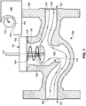
FIG. 1 comprises a schematic front elevation cross-sectional view of an exemplary torsional spring actuated thermal valve in accordance with various embodiments of the invention; -
FIG. 2 comprises a schematic front elevation cross-sectional view of the exemplary torsional spring actuated thermal valve ofFIG. 1 in an activated position in accordance with various embodiments of the invention; -
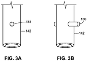
FIGS. 3A & 3B comprise schematic perspective views of a set pin coupled to an inner telescoping component of the exemplary torsional spring actuated thermal valve ofFIGS. 1 and2 in accordance with various embodiments of the invention; -
FIGS 4A-4D comprise schematic front elevation cross sectional views of an outer telescoping component of the exemplary torsional spring actuated thermal valve ofFIGS 1 and2 in accordance with various embodiments of the invention; and -
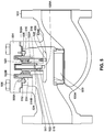
FIG. 5 comprises a schematic front elevation cross-sectional view of an exemplary version of a pin-release thermal valve in accordance with various embodiments of the invention - Skilled artisans will appreciate that elements in the figures are illustrated for simplicity and clarity and have not necessarily been drawn to scale. For example, the dimensions and/or relative positioning of some of the elements in the figures may be exaggerated relative to other elements to help to improve understanding of various embodiments of the present invention. Also, common but well-understood elements that are useful or necessary in a commercially feasible embodiment are often not depicted in order to facilitate a less obstructed view of these various embodiments. It will further be appreciated that certain actions and/or steps may be described or depicted in a particular order of occurrence while those skilled in the art will understand that such specificity with respect to sequence is not actually required. It will also be understood that the terms and expressions used herein have the ordinary technical meaning as is accorded to such terms and expressions by persons skilled in the technical field as set forth above except where different specific meanings have otherwise been set forth herein.
- According to the present invention, there is provided a valve including a valve body forming a channel defining a fluid flow path extending from an inlet port of the valve body to an outlet port of the valve body via a gallery of the valve body that is disposed between the inlet port and the outlet port. The fluid flow path is adapted to allow a fluid to flow through the valve body in a first direction and a second direction opposite the first direction. The valve body further defines an opening disposed in communication with the gallery, a valve assembly adapted to be at least partially disposed through the opening and in the gallery of the valve body, and a set pin having a central longitudinal axis. The valve assembly includes a valve stem defining an opening and a catch region, a valve spring, a valve disc coupled with the valve stem, and a valve bonnet at least partially covering the opening and coupled with the valve stem, the valve spring being at least partially disposed between the bonnet and the valve disc. The valve disc is movable between a first position spaced from a valve seat of the valve body and a second position in contact with the valve seat upon the valve spring exerting a downward force on the valve disc and the valve stem. The set pin is disposed within the fluid flow path. The set pin is adapted to be at least partially disposed in the opening of the valve stem and retained by the catch region to maintain the valve assembly in the first position by contacting a peripheral edge portion of the catch region which exerts a reactionary force on the set pin. The valve stem comprises a first telescoping component having a central longitudinal axis and a second telescoping component having a central longitudinal axis aligned with the central longitudinal axis of the first telescoping component and forming the catch region. The set pin is coupled to a portion of the first telescoping component. The set pin is adapted to disengage the catch region of the valve assembly when the set pin and/or valve assembly is contacted by a fluid traversing the fluid flow path in the second direction during a deflagration event such that the valve spring exerts a force on the valve disc of the valve assembly to move the valve disc to the second position, the set pin disengaging the catch region by at least one of:
- a) a force exerted on the set pin and/or the valve assembly by the fluid traversing the fluid flow path in the second direction being sufficient to move the set pin in a direction generally parallel to the central longitudinal axis to disengage the set pin from the catch and the valve spring being a torsional spring contacting the set pin causing the set pin to pivot off a center of gravity thereof thereby releasing the set pin; or
- b) the valve spring being a torsional spring attached to the valve bonnet and the valve disc and expansion of which due to increased temperatures associated with a deflagration event is sufficient to cause the set pin to rotate and disengage the catch region of the valve assembly upon the fluid traversing the fluid flow path in the second direction.
- The valve stem may comprise a first telescoping component having a central longitudinal axis and a second telescoping component having a central longitudinal axis aligned with the central longitudinal axis of the first telescoping component and forming at least one catch through a cylindrical surface thereof.
- The valve spring may exert a force on the set pin to urge the valve disc toward the second position. The valve assembly may be removably disposed within the valve body. In some examples, the valve assembly may be repeatedly secured in the first position by retaining the set pin via the catch of the second telescoping component.
- The set pin may comprise a generally cylindrical member disposed generally perpendicular to the central longitudinal axis of the first and/or the second component. The set pin may comprise any one of a spring pin, a dowel pin, fasteners, and the like. Other examples are possible. The set pin may be inserted through at least one opening of the first telescoping component to couple the set pin thereto. In other examples, the set pin is affixed to an outer portion of the first telescoping component to couple the set pin thereto. Other examples are possible. The catch may comprise a blind hole disposed on an inner surface of the second telescoping component. Other examples are possible.
- In the present teachings, a valve assembly is disclosed which may include a valve bonnet adapted to at least partially cover an opening of a valve body, a valve stem coupled to the valve bonnet, a valve disc coupled to the valve stem opposite the valve bonnet, a set pin having a central longitudinal axis, and a valve spring at least partially disposed between the valve bonnet and the valve disc. The valve stem and the valve disc are movable between a first position wherein the valve disc is spaced a first distance from the bonnet and a second position wherein the valve disc is spaced a second distance away from the valve bonnet, whereby the second distance is greater than the first distance. The set pin is adapted to be coupled to and at least partly supported by the valve stem to maintain the valve stem and the valve disc in the first position. The valve spring exerts a force on at least one of the valve stem, the set pin, and the valve disc, thereby urging the valve stem and the valve disc into the second position. Upon the set pin disengaging a portion of the valve stem, the valve spring is adapted to cause the valve stem and the valve disc to move to the second position.
- The valve stem may comprise a first telescoping component having a central longitudinal axis and a second telescoping component having a central longitudinal axis aligned with the central longitudinal axis of the first telescoping component and forming at least one opening on a cylindrical surface thereof. In these examples, the set pin is coupled to a portion of the first telescoping component to maintain the valve assembly in the first position. In some approaches, the central longitudinal axis of the set pin is adapted to be substantially perpendicular to the central longitudinal axes of the first and second telescoping components when the set pin is at least partly supported by the valve stem.
- So configured, the valve assembly and other components are substantially removed from the fluid flow path, thus creating a smoother flow, which in turn reduces turbulence and the occurrence of detonation events. In these examples, it is understood that the thermal valve will be used on an unprotected side of a flame arrestor commonly used in existing systems. While the thermal valve may not prevent all flames from progressing to the flame arrestor, the valve's closure will ultimately shut off the remaining gas flow which will result in the flame burning out. Further, upon the occurrence of a deflagration event in which the set pin disengages the catch, the valve assembly may be easily reset by repositioning the set pin to engage the catch. Additionally, because portions of the valve assembly may be a unitary design inserted into the opening of the valve body, it may be easily replaceable should components be damaged beyond repair by a deflagration event.
- Referring now to the drawings, and in particular to
FIGS. 1 and2 , avalve 100 for an oil and gas tank is provided. The valve includes avalve body 108, avalve assembly 110, and aset pin 130. Thevalve body 108 forms abonnet opening 103 and further forms achannel 104 which defines a fluid flow path extending from aninlet port 101 of thevalve body 108 to an outlet port 102 of thevalve body 108 via agallery 105. The fluid may flow along thechannel 104 in a first direction 106 (e.g., from theinlet port 101 to the outlet port 102) or a second direction 107 (e.g., from the outlet port 102 to the inlet port 101). Thevalve 100 also forms avalve seat 114 located in thegallery 105. - Generally speaking, the
valve 100 is adapted to be disposed between a storage tank and flame arrestor (not shown) and upstream components (not shown) for use and/or processing. Thevalve body 108 may be constructed of any number of metallic materials and is formed using any number of methods, such as, for example, extruding, forging, and the like. Other examples are possible. It is understood that thevalve 100 may include any number of additional components not described herein for the sake of brevity. - It is understood that by the term "fluid" and as described herein, it is meant any suitable liquids and/or gases which may be stored and utilized in oil and gas applications. For example, suitable fluids may include Group D gases such as methane, propane, and/or natural gas. Other examples are possible. These fluids may generate flames or deflagration events upon experiencing a substantial amount of turbulent flow. Other examples are possible.
- The
valve assembly 110 may include avalve bonnet 112 adapted to at least partially cover thebonnet opening 103 of thevalve body 108, avalve stem 140, avalve disc 118, and avalve spring 120. The individual components of thevalve assembly 110 may be constructed of any number of suitable materials, such as, for example, metals, metal alloys, polymers, and the like. Other examples are possible. - In some examples, the
valve bonnet 112 is a generally planar component which may serve as a partial or complete seal to thebonnet opening 103. Thevalve bonnet 112 may be coupled to thevalve body 108 using any number of components such as, for example, nuts, bolts, screws, clamps, and the like. Other examples are possible. - The valve stem 140 may be coupled to the
valve bonnet 112 using any number of suitable components and techniques. The valve stem 140 may have a central longitudinal axis L1 and may include at least one opening extending along a lateral axis L2 which is transverse to the longitudinal axis L1. In the disclosed versions, the lateral axis L2 is approximately perpendicular to the central longitudinal axis L1 of thevalve stem 140. Thevalve stem 140 is adapted to move between a first position (FIG. 1 ) and a second position (FIG. 2 ) via any number of components. - As will be described, the first position may be described as a "loaded" position and the second position may be described as an "activated" position. For example, the
valve stem 140 may comprise a telescopic tube element including a first telescoping component 142 (also referred to as an "inner tube") slidably disposed within a second telescoping component 150 (also referred to as an "outer tube"). In the disclosed embodiment, theouter tube 150 is fixed to thevalve bonnet 112 and theinner tube 142 is axially displaceable relative to theouter tube 150, as will be described. In other versions, theinner tube 142 can be fixed to thevalve bonnet 112 and theouter tube 150 could be slidably displaceable relative to theinner tube 142 and thevalve bonnet 112. In still other versions, thevalve stem 140 may include more than two telescoping components (also referred to as "tubes") while achieving the same desired purpose. - In this example, the
inner tube 142 and theouter tube 150 have a common central longitudinal axis L1. Theinner tube 142 is dimensioned such that it may be inserted into theouter tube 150. In some examples, theinner tube 142 may have an outer diameter of approximately 5 to 15 millimeters, and more specifically, approximately 11 millimeters. Furthermore, theouter tube 150 may have an inner diameter of approximately 7 to 17 millimeters, and more specifically, approximately 13 millimeters. Other examples are possible. Further, theouter tube 150 may have anopening 152 along the lateral axes L2 which corresponds with a portion of theinner tube 142 when thevalve stem 140 is in the first, loaded position. Other examples are possible. In some examples, theinner tube 142 may have an opening or indentation for inserting theset pin 130. - The
valve seat 114 is at least partially formed by thevalve body 108 and is disposed between theinlet port 101 and the outlet port 102 of thevalve body 108. In some examples, thevalve seat 114 may be a ledge or platform having a cross sectional shape identical or similar to that of thechannel 104. It is understood that thevalve seat 114 may be an integral component of thevalve body 108 or may include separate components such as a seat ring attached to thevalve body 108 using any number of methods such as threads, screws, and the like. Other examples are possible. - The
valve disc 118 is adapted to be coupled to thevalve stem 140 and, in particular, a distal end of theinner tube 142 of the disclosedvalve stem 140. Thevalve spring 120 is adapted to be at least partially disposed between thevalve bonnet 112 and thevalve disc 118 and is adapted to exert a force (denoted by "F" in the drawings) on at least one of thevalve stem 140, theset pin 130, and thevalve disc 118. In the disclosed version, thevalve spring 120 exerts a downward force on thevalve disc 118 andinner tube 142 of thevalve stem 140, which in turn applies a shear load to theset pin 130 as will be described. - The
set pin 130 or link may be any type of generally cylindrically shaped and thus have a generally circular cross sectional area. It is understood that any cross sectional shape may be used as desired. Theset pin 130 may be constructed of any number of materials (e.g., stainless steel or other high-temperature metals) and may be chosen based on the material's physical properties such as melting point, shear strength, bending resistance, etc. In some examples, theset pin 130 comprises a spring pin which may include a slot running along a portion of its longitudinal length. In other examples, theset pin 130 may comprise either a hollow or solid dowel pin. Other examples are possible. - The
set pin 130 may be coupled to theinner tube 142 of thevalve stem 140 via any number of suitable methods. As illustrated inFIGS. 3A & 3B , theinner tube 142 may include at least one indentation or opening 144 on an outer surface thereof which is aligned with the lateral axis L2. Theset pin 130 may be partially inserted into theindentation 144 to couple theset pin 130 to theinner tube 142. This coupling between theset pin 130 and theinner tube 142 may be a threaded connection, a press-fit connection, or any other suitable connection. In some examples in which theinner tube 142 includes an opening through a portion thereof, theset pin 130 may be inserted through theopening 144. It is understood that any number of set pins 130 may be used as desired depending on the number ofindentations 144 contained on theinner tube 142. For example, in embodiments having twoindentations 144 on opposing sides of theinner tube 142, two setpins 130 may be used. - As illustrated in
FIGS. 1 &4A-4D , theouter tube 150 may include an opening oropenings 152 which align with the lateral axis L2 when thevalve stem 140 is in the loaded position. Theopening 152 may include acatch region 154 which acts to restrict movement of theinner tube 142 and theset pin 130 from moving along the lateral axis L1 relative to theouter tube 150. In some examples, theopening 152 may extend completely through the shell of theouter tube 150, but in other examples, theopening 152 may comprise a blind hole or opening disposed on an inner surface of theouter tube 150. As Illustrated inFIGS. 4A-4D , theopening 152 may be formed in any number of configurations. Theopening 152 may comprise a circumferential region of theouter tube 150, which may cause the outer tube to have a protruding end that lacks a generally uniform and/or cylindrical design. - In operation, and as illustrated in
FIG. 1 ,valve stem 140 andvalve disc 118 are moved to the first position, which causes thevalve spring 120 to compress. Theset pin 130 is coupled to theinner tube 142 and moved into theopening 152 of theouter tube 150. As a result, theset pin 130 therefore resides along the lateral axis L2 which in the disclosed example is generally perpendicular to the longitudinal axis L1 of thevalve stem 140 to restrict movement of theinner tube 142 andvalve disc 118 relative to theouter tube 150. Because thevalve spring 120 is in a compressed state, theset pin 130 is urged in a direction along the lateral axis L1. Theset pin 130 contacts a lower peripheral edge portion of thecatch region 154 which exerts a reactionary force on theset pin 130. These combined forces will in turn maintain theset pin 130 within theopening 152 as well as thevalve assembly 110 in the first or "loaded" position. Accordingly, thevalve assembly 110 is maintained in this loaded position without thevalve stem 140, setpin 130, orvalve spring 120 interacting with, contacting, or bearing against portions of thevalve body 108 for support. Thevalve bonnet 112, thevalve stem 140, thevalve disc 118, and thevalve spring 120 may then be inserted into thebonnet opening 103 of thevalve body 108 and coupled thereto via thevalve bonnet 112. - When the
valve assembly 110 is in the first position, fluid may move freely along the firstfluid flow path 106. This is because thevalve assembly 110 is spaced away from thevalve seat 114 and substantially out of thefluid flow path 106. Said another way, a substantial part of the fluid flow path through thegallery 105 of thevalve body 108 where thevalve assembly 110 is in the first position is entirely free of physical obstructions. Thefirst direction 106 of the fluid flow path may be used to transport fluids from the storage tank to upstream components for use and/or processing. When a fluid moves along the fluid flow path in thefirst direction 106, theset pin 130 remains substantially out of contact with the fluid. In some embodiments, a substantial portion of the components in thevalve assembly 110 also remain out of contact with the fluid during movement along thefirst direction 106. As such, the fluid flow is smooth and generally free of interruptions and/or bends which may create turbulent flow. It is understood that in some embodiments, the fluid moving along the firstfluid flow path 106 may contact any or all of theset pin 130 and any number of components in thevalve assembly 110, but the fluid travel may still remain generally free of turbulence. - As illustrated in
FIG. 2 , in the event of a deflagration event in which a flame and its corresponding fluids travel back towards the storage tank and into thevalve 100 in thesecond direction 107 of the fluid flow path, the fluid may contact theset pin 130. Generally speaking, forces exerted on theset pin 130 and the other components of thevalve assembly 110 cause the set pin to disengage thecatch region 154. Upon disengaging thecatch region 154, the force exerted by thespring 120 will cause thevalve assembly 110 to move from the first position to the second position. - When a portion of the
valve assembly 110 moves to the second, activated position, theinner tube 142 moves axially relative to theouter tube 150 such that thevalve disc 118 contacts thevalve seat 114 and creates a seal which restricts fluids from propagating beyond thevalve seat 114 in thesecond direction 107. In the disclosed version and as illustrated inFIG. 2 , theinner tube 142 slides partly out of theouter tube 150 as thevalve stem 140 moves from the first position to the second position. As a result, while an amount of fluid and/or flame may have propagated beyond thevalve stem 114 before thevalve assembly 110 moved to the second position, the flame will eventually burn out due to a lack of fluid supplied thereto. Further, in some examples, when thevalve assembly 110 is in the second position, movement along the fluid flow path in thefirst direction 106 may also be restricted. - In some examples, the force of the fluid propagating the fluid flow path in the
second direction 107 may be sufficient to "lift" theset pin 130 out of thecatch region 154 and cause theset pin 130 to disengage theopening 152, which in turn will cause thevalve assembly 110 to move to the second position. In other examples, thevalve spring 120 may be constructed of a material which expands when experiencing the increased temperatures associated with the deflagration event. This expansion may be sufficient to cause theset pin 130 to rotate and disengage thecatch region 154, thus causing thevalve assembly 110 to move to the second position. - Because the
first direction 106 and thesecond direction 107 contain a minimal number of changes in overall direction, interruptions, edges, and/or other flow-disturbing components, the chances of generating turbulent flow are minimized. As a result, even in the event of a deflagration event in which a fluid is propagating in thesecond direction 107, the likelihood of creating a potentially catastrophic detonation event is substantially reduced. Further, despite portions of thevalve assembly 110 being disposed at a position which may be contacted by a fluid propagating in thesecond direction 107, the occurrence detonation events remains unlikely. - Since the
valve assembly 110 may be readily coupled together, it is possible to easily reset theset pin 130 as well as easily replace damaged components. For example, in the event that a deflagration event occurs in which a fluid propagates in thesecond direction 107, while theset pin 130 may have disengaged thecatch region 154, thevalve assembly 110 may be reset by removing thevalve bonnet 112, thevalve stem 140, thevalve disc 118, and thevalve spring 120 by decoupling thevalve bonnet 112 from thevalve body 108. The valve stem 140 may then be reset in the first "loaded" position by engaging theset pin 130 to theopening 152 of theouter tube 150. Thevalve assembly 110 may then be reinserted into thebonnet opening 103 of thevalve body 108. - Turning to
FIGS. 4A-4D , various approaches for engaging theset pin 130 to theouter tube 150 are provided. As previously described, inFIG. 4A , the set pin (not shown) rests in theopening 152 and is constrained by thecatch 154. It is understood that theopening 152 may be of any suitable size, length, and/or configuration. InFIG. 4B , theset pin 130 is at least partially semi-cylindrical in length and again rests in theopening 152 and is constrained by thecatch 154. In this example, when the valve assembly is in the loaded position whereby theset pin 130 is constrained by thecatch 154, the center of gravity of theset pin 130 is located at a position that causes theset pin 130 to be maintained in the loaded position. When thevalve spring 120 is contacted by the fluid propagating the fluid flow path in thesecond direction 107, thevalve spring 120 may contact theset pin 130, causing it to pivot off of the center of gravity thereby releasing the set pin and causing the valve assembly to move to the activated position. - As shown in
FIG. 4C , theset pin 130 is at least partially triangular in length. Theset pin 130 includes anotch 132 which corresponds to thecatch 154 of theouter tube 150. Similar to previous examples, when the valve assembly is in the loaded position whereby thenotch 132 is constrained by thecatch 154, the center of gravity of theset pin 130 is located at a position that causes theset pin 130 to be maintained in the loaded position. When thevalve spring 120 is contacted by the fluid propagating the fluid flow path in thesecond direction 107, thevalve spring 120 contacts theset pin 130, causing it to pivot off of the center of gravity thereby releasing theset pin 130 and causing the valve assembly to move to the activated position. - In other examples, and as illustrated in
FIG. 4D , theouter tube 150 may include a number of indentations or steps which form a number ofopenings outer tube 150 as desired. Theopenings set pin 130. In some examples, thecatches set pin 130 to move into theopenings catches openings set pin 130 may be inserted into any one of theopenings valve spring 120 is contacted by the fluid propagating the fluid flow path in thesecond direction 107, thevalve spring 120 causes theset pin 130 to move out of theopening set pin 130 and causing the valve assembly to move to the activated position. - Turning to
FIG. 5 , a detailed schematic of an alternative valve 500 is provided. The valve 500 includes avalve body 502, anorifice 503, abonnet 504,bonnet bolts 506, anouter guide clamp 508, outer guide clamp screws 510, agasket 512, anouter guide 514, astem 516, astem opening 517, aset pin 518, aspring 520, aspring support 522, astem guide 524, a disc orpallet 526, and pallet screws 528. - The
valve body 502 and thebonnet 504 may be made of any number of suitable metals such as stainless steel (e.g., 316 stainless steel). Thegasket 512 may be constructed of graphite, rubbers, or any other suitable materials and may be flame-resistant. Thegasket 512 is disposed in an opening of thevalve body 502 to create a seal to prevent leakage of pipe line fluid to the atmosphere. Thebonnet 504 is coupled to thevalve 502 via any number ofbonnet bolts 506, which may be constructed of metals such as stainless steel (e.g., a combination 304/316 stainless steel yield material). Other examples are possible. Thebonnet 504 is responsible for securing the remainder of the valve assembly to thevalve 502. - The
outer guide 514 may be a cylindrical tube-like structure adapted to couple to the bonnet and is adapted to prevent thespring support 522 from extending past a certain point and will be described in further detail below. Theouter guide 514 may be made of any number of suitable metals such as stainless steel (e.g., 316 stainless steel). Theouter guide 514 may be coupled to thebonnet 504 via theouter guide clamp 508 using the outer guide clamp screws 510. It is understood that any number of outer guide clamp screws 510 may be used to couple theouter guide 514 to thebonnet 504. Theouter guide 514 may include a first notch or protrusion 514A which is adapted to contact aledge 508A of the outer guide clamp. Theouter guide clamp 508 and outer guide clamp screws 510 may be made of any number of suitable metals such as stainless steel (e.g., 316 stainless steel). Other examples are possible. - The
spring 520 may be constructed of any suitable material such as a metal and/or metallic alloy (e.g., an austenite nickel-chromium-based superalloy commonly referred to as Inconel). Other examples are possible. Thespring 520 is positioned against thebonnet 504 on a first end and is supported by aledge 522A of thespring support 522 on a second end thereof. Thespring support 522 may be made of any number of suitable metals such as stainless steel (e.g., 316 stainless steel). Other examples are possible. - Disposed inside a central portion of the
spring 520 is astem guide 524. Thestem guide 524 may be made of any number of suitable metals such as stainless steel (e.g., 316 stainless steel) and may be coupled to thebonnet 504 via a threaded connection or other suitable methods. Thestem guide 524 is adapted to guide thestem 516 disposed therein as thepallet 526 moves between a first and a second position. Thestem guide 524 includes anopening 517 which serves as a catch or stop (such as those previously described herein) to restrict thestem 516 from moving. - The
stem 516 and thepallet 526 may be constructed of any number of suitable materials such as stainless steel (e.g., 410 stainless steel or other suitable materials). Thestem 516 may be coupled to thepallet 526 via any number of connections, such as a threaded connection, a press-fit connection via acentral bore 526A in the pallet, or any other suitable method. Thepallet 526 may be coupled to thespring support 522 via pallet screws 528 to ensure forces exerted by thespring 520 are evenly distributed on thepallet 526. As such, thepallet 526 may include a counter bore to create a planar surface. - The
set pin 518 may be an elongated component constructed of any suitable material or metals such as a stainless steel. It is understood that theset pin 518 may be any suitable shape such as cylindrical or cuboidal. Other examples are possible. Theset pin 518 may be coupled to thestem 516 via any number of approaches, including those previously described with reference toFIGS. 1-4 . Theset pin 518 is adapted to be inserted into theopening 517 of thestem guide 524. By inserting theset pin 518 into the opening, the assembly is locked in a first position whereby thespring 520 causes a downward force to be exerted on theset pin 518, thereby retaining theset pin 518 within theopening 517. - Upon the
set pin 518 disengaging theopening 517 due to a deflagration event, thespring 520 causes thestem 516 andpallet 526 to move towards theorifice 503. This lateral movement is guided by thestem guide 524,spring support 522, and theouter guide 514 to ensure proper alignment of thepallet 526. Theorifice 503 includes a parabolic surface 503A which is adapted to contact a correspondingparabolic surface 526B on thepallet 526 to ensure thepallet 526 maintains contact with the edge of theorifice 503 to seal and stop flow from traveling through the valve. - When it is desired to remove the valve assembly from the
valve 502, thebonnet bolts 506 may be unbolted and thebonnet 504 and the assembly may be removed from the opening. During removal, asecond notch 514B of theouter guide 514 may contact acorresponding notch 522B or lip of thespring support 522 to capture the entire assembly for removal.
Claims (9)
- A valve (100) comprising:a valve body (108) forming a channel (104) defining a fluid flow path extending from an inlet port (101) of the valve body (108) to an outlet port (102) of the valve body (108) via a gallery (105) of the valve body (108) that is disposed between the inlet port (101) and the outlet port (102), wherein the fluid flow path is adapted to allow a fluid to flow through the valve body (108) in a first direction (106) and a second direction (107) opposite the first direction (106), the valve body (108) further defining an opening (103) disposed in communication with the gallery (105);a valve assembly (110) adapted to be at least partially disposed through the opening (103) and in the gallery (105) of the valve body (108), the valve assembly (110) including a valve stem (140) defining an opening (152) and a catch region (154), a valve spring (120), a valve disc (118) coupled with the valve stem (140), and a valve bonnet (112) at least partially covering the opening (103) and coupled with the valve stem (140), the valve spring (120) being at least partially disposed between the bonnet (112) and the valve disc (118), wherein the valve disc (118) is movable between a first position spaced from a valve seat (114) of the valve body (108) and a second position in contact with the valve seat (114) upon the valve spring (120) exerting a downward force on the valve disc (118) and the valve stem (140); anda set pin (130) having a central longitudinal axis and being disposed within the fluid flow path, the set pin (130) adapted to be at least partially disposed in the opening (152) of the valve stem (140) and retained by the catch region (154) to maintain the valve assembly (110) in the first position by contacting a peripheral edge portion of the catch region (154) which exerts a reactionary force on the set pin (130);wherein the valve stem (140) comprises a first telescoping component (142) having a central longitudinal axis and a second telescoping component (150) having a central longitudinal axis aligned with the central longitudinal axis of the first telescoping component (142) and forming the catch region (154);wherein the set pin (130) is coupled to a portion of the first telescoping component (142);wherein the set pin (130) is adapted to disengage the catch region (154) of the valve assembly (110) when the set pin (130) and/or valve assembly (110) is contacted by a fluid traversing the fluid flow path in the second direction (107) during a deflagration event such that the valve spring (120) exerts a force on the valve disc (118) of the valve assembly (110) to move the valve disc (118) to the second position, the set pin (130) disengaging the catch region (154) by at least one of:a) a force exerted on the set pin (130) and/or the valve assembly (110) by the fluid traversing the fluid flow path in the second direction (107) being sufficient to move the set pin (130) in a direction generally parallel to the central longitudinal axis to disengage the set pin (130) from the catch (154) and the valve spring (120) being a torsional spring contacting the set pin (130) causing the set pin (130) to pivot off a center of gravity thereof thereby releasing the set pin (130); orb) the valve spring (120) being a torsional spring attached to the valve bonnet (112) and the valve disc (118) and expansion of which due to increased temperatures associated with a deflagration event is sufficient to cause the set pin (130) to rotate and disengage the catch region (154) of the valve assembly (110) upon the fluid traversing the fluid flow path in the second direction (107).
- The valve (100) of claim 1, wherein the second telescoping component (150) forms the catch region (154) through a cylindrical surface thereof.
- The valve (100) of any of the preceding claims, wherein the
valve spring (120) causes the valve disc (118) to contact the valve seat (114) upon the set pin (130) disengaging the catch region (154) of the valve assembly (110). - The valve (100) of any of the preceding claims, wherein the set pin (130) comprises a generally cylindrical member being disposed generally perpendicularly to the central longitudinal axis.
- The valve (100) of any of the preceding claims, wherein the set pin (130) comprises at least one of:(a) a spring pin,(b) a dowel pin,(c) a fastener.
- The valve (100) of claim 1, wherein the set pin (130) is inserted through at least one opening (144) of the first telescoping component (142) to couple the set pin (130) to the first telescoping component (142).
- The valve (100) of claim 1, wherein the set pin (130) is affixed to an outer surface of the first telescoping component (142) to couple the set pin (130) to the first telescoping component (142).
- The valve (100) of claim 1, wherein the catch (154) comprises a blind hole disposed on an inner surface of the second telescoping component (150).
- The valve (100) of claim 1, wherein the valve assembly (110) is adapted to be repeatedly secured in the first position by retaining the set pin (130) by the catch (154) of the second telescoping component (150).
Applications Claiming Priority (2)
| Application Number | Priority Date | Filing Date | Title |
|---|---|---|---|
| US15/040,877 US10274099B2 (en) | 2016-02-10 | 2016-02-10 | Spring actuated thermal valve |
| PCT/US2017/017287 WO2017139522A1 (en) | 2016-02-10 | 2017-02-10 | Torsional spring actuated thermal valve |
Publications (2)
| Publication Number | Publication Date |
|---|---|
| EP3413982A1 EP3413982A1 (en) | 2018-12-19 |
| EP3413982B1 true EP3413982B1 (en) | 2021-09-22 |
Family
ID=58108745
Family Applications (1)
| Application Number | Title | Priority Date | Filing Date |
|---|---|---|---|
| EP17706934.1A Active EP3413982B1 (en) | 2016-02-10 | 2017-02-10 | Torsional spring actuated thermal valve |
Country Status (5)
| Country | Link |
|---|---|
| US (2) | US10274099B2 (en) |
| EP (1) | EP3413982B1 (en) |
| CN (2) | CN207131868U (en) |
| MX (1) | MX2018009657A (en) |
| WO (1) | WO2017139522A1 (en) |
Families Citing this family (5)
| Publication number | Priority date | Publication date | Assignee | Title |
|---|---|---|---|---|
| EP3792527A1 (en) | 2019-09-10 | 2021-03-17 | Alfa Laval Corporate AB | Gasket, fluid flow control valve and method of cleaning such a valve |
| US11989043B2 (en) | 2021-08-30 | 2024-05-21 | Kalsi Engineering, Inc. | Miniature passive thermal control valve for mixing or splitting single-phase fluid with adjustable thermal actuator |
| CN114087374B (en) * | 2021-11-18 | 2023-09-05 | 新乡航空工业(集团)有限公司 | Diaphragm and solenoid valve combined control's split type filling valve |
| CN115582067B (en) * | 2022-11-25 | 2023-06-09 | 扬州工业职业技术学院 | Medicament delivery device for water treatment |
| US11953161B1 (en) | 2023-04-18 | 2024-04-09 | Intelcon System C.A. | Monitoring and detecting pipeline leaks and spills |
Family Cites Families (12)
| Publication number | Priority date | Publication date | Assignee | Title |
|---|---|---|---|---|
| GB190916000A (en) | 1908-08-03 | 1909-12-16 | Joanny Lombard | Improvements in Automatic Stop-valves for Steam Generators. |
| DE534800C (en) | 1930-10-07 | 1931-10-05 | Askania Werke A G Vormals Cent | Safety valve |
| US2721571A (en) * | 1954-12-21 | 1955-10-25 | Gershon Milton | Shut-off valve |
| US3381933A (en) * | 1965-12-28 | 1968-05-07 | Derhammer Eli | Automatic safety cut-off valve |
| US3779262A (en) | 1972-01-12 | 1973-12-18 | M Manning | Seismically sensitive safety device |
| US4116209A (en) | 1977-05-05 | 1978-09-26 | Greer Charles W | Shock actuated shut-off valve |
| US5685329A (en) * | 1995-10-05 | 1997-11-11 | Taylor; Julian S. | Dual inline rupture pin release and reseating spring loaded relief valve |
| US6497372B2 (en) * | 2000-12-07 | 2002-12-24 | Jae-Heung Lee | Automatic temperature control valve |
| CN202484376U (en) * | 2011-04-15 | 2012-10-10 | 艾默生过程管理调节技术公司 | Cam assembly applied in emergency cut-out safety valve and emergency cut-out safety valve applied in gas distribution system |
| US10704815B2 (en) * | 2014-04-28 | 2020-07-07 | Bosch Automotive Service Solutions Llc | Flow control valve for injecting oil into an air conditioning circuit |
| CN204493752U (en) * | 2015-03-17 | 2015-07-22 | 永嘉县恒正阀门有限公司 | A kind of can the stop valve of flow setting type |
| CN205001588U (en) * | 2015-09-02 | 2016-01-27 | 上海中沪阀门(集团)有限公司 | Venting explosion valve |
-
2016
- 2016-02-10 US US15/040,877 patent/US10274099B2/en active Active
-
2017
- 2017-02-10 WO PCT/US2017/017287 patent/WO2017139522A1/en not_active Ceased
- 2017-02-10 EP EP17706934.1A patent/EP3413982B1/en active Active
- 2017-02-10 CN CN201720123764.9U patent/CN207131868U/en active Active
- 2017-02-10 CN CN201710074116.3A patent/CN107061750B/en active Active
- 2017-02-10 MX MX2018009657A patent/MX2018009657A/en unknown
-
2019
- 2019-04-29 US US16/397,526 patent/US11085551B2/en active Active
Also Published As
| Publication number | Publication date |
|---|---|
| WO2017139522A1 (en) | 2017-08-17 |
| MX2018009657A (en) | 2019-07-04 |
| CN107061750A (en) | 2017-08-18 |
| US11085551B2 (en) | 2021-08-10 |
| CN107061750B (en) | 2020-10-16 |
| US20170227137A1 (en) | 2017-08-10 |
| CN207131868U (en) | 2018-03-23 |
| US20190285189A1 (en) | 2019-09-19 |
| EP3413982A1 (en) | 2018-12-19 |
| US10274099B2 (en) | 2019-04-30 |
Similar Documents
| Publication | Publication Date | Title |
|---|---|---|
| US11085551B2 (en) | Torsional spring actuated thermal valve | |
| US5551476A (en) | Balanced-flow gas safety valve | |
| US10174855B2 (en) | Pin release thermal valve | |
| US6920895B2 (en) | Combination surge supression and safety shut-off valve | |
| US2482198A (en) | Valve structure | |
| US8490639B2 (en) | Temperature sensitive valve | |
| US9884213B2 (en) | Thermal valve in upstream oil and gas | |
| JPS6299591A (en) | Top entry trunnion ball valve | |
| BR0101219B1 (en) | underwater hydraulic connection. | |
| BR112013030030B1 (en) | pressure balanced fluid pressure regulators | |
| JP4987869B2 (en) | Fitting assembly | |
| CN209340718U (en) | Anti-shock devices and pipeline components for installation in pipelines | |
| JP4666626B2 (en) | Backfire back pressure prevention device | |
| US9383025B2 (en) | Excess flow valve with cage | |
| CN117980641A (en) | Relief Valves and Systems | |
| CN205424037U (en) | Use solenoid valve on burner flame out protection device | |
| US20120272636A1 (en) | Combustor drain valve and assembly | |
| JP3600609B2 (en) | Channel cutoff device | |
| JP2004156708A (en) | Gas cut-off device | |
| JP2007078001A (en) | Flow path opening and closing valve and its parts | |
| JP2005344862A (en) | Gas cut-off device | |
| Hartmann et al. | Analysis of supports of a three-legged compliant snap-through structure for application in an excess flow valve | |
| JPH09100977A (en) | Gas connecting method and pipe joint used therefor |
Legal Events
| Date | Code | Title | Description |
|---|---|---|---|
| STAA | Information on the status of an ep patent application or granted ep patent |
Free format text: STATUS: UNKNOWN |
|
| STAA | Information on the status of an ep patent application or granted ep patent |
Free format text: STATUS: THE INTERNATIONAL PUBLICATION HAS BEEN MADE |
|
| PUAI | Public reference made under article 153(3) epc to a published international application that has entered the european phase |
Free format text: ORIGINAL CODE: 0009012 |
|
| STAA | Information on the status of an ep patent application or granted ep patent |
Free format text: STATUS: REQUEST FOR EXAMINATION WAS MADE |
|
| 17P | Request for examination filed |
Effective date: 20180905 |
|
| AK | Designated contracting states |
Kind code of ref document: A1 Designated state(s): AL AT BE BG CH CY CZ DE DK EE ES FI FR GB GR HR HU IE IS IT LI LT LU LV MC MK MT NL NO PL PT RO RS SE SI SK SM TR |
|
| AX | Request for extension of the european patent |
Extension state: BA ME |
|
| DAV | Request for validation of the european patent (deleted) | ||
| DAX | Request for extension of the european patent (deleted) | ||
| STAA | Information on the status of an ep patent application or granted ep patent |
Free format text: STATUS: EXAMINATION IS IN PROGRESS |
|
| 17Q | First examination report despatched |
Effective date: 20190905 |
|
| REG | Reference to a national code |
Ref country code: DE Ref legal event code: R079 Ref document number: 602017046329 Country of ref document: DE Free format text: PREVIOUS MAIN CLASS: A62C0004020000 Ipc: A62C0003060000 |
|
| GRAP | Despatch of communication of intention to grant a patent |
Free format text: ORIGINAL CODE: EPIDOSNIGR1 |
|
| STAA | Information on the status of an ep patent application or granted ep patent |
Free format text: STATUS: GRANT OF PATENT IS INTENDED |
|
| RIC1 | Information provided on ipc code assigned before grant |
Ipc: F16K 17/34 20060101ALI20210305BHEP Ipc: F16K 17/32 20060101ALI20210305BHEP Ipc: A62C 4/02 20060101ALI20210305BHEP Ipc: F16K 17/36 20060101ALI20210305BHEP Ipc: A62C 3/06 20060101AFI20210305BHEP |
|
| INTG | Intention to grant announced |
Effective date: 20210408 |
|
| GRAS | Grant fee paid |
Free format text: ORIGINAL CODE: EPIDOSNIGR3 |
|
| GRAA | (expected) grant |
Free format text: ORIGINAL CODE: 0009210 |
|
| STAA | Information on the status of an ep patent application or granted ep patent |
Free format text: STATUS: THE PATENT HAS BEEN GRANTED |
|
| AK | Designated contracting states |
Kind code of ref document: B1 Designated state(s): AL AT BE BG CH CY CZ DE DK EE ES FI FR GB GR HR HU IE IS IT LI LT LU LV MC MK MT NL NO PL PT RO RS SE SI SK SM TR |
|
| REG | Reference to a national code |
Ref country code: GB Ref legal event code: FG4D |
|
| REG | Reference to a national code |
Ref country code: IE Ref legal event code: FG4D |
|
| REG | Reference to a national code |
Ref country code: DE Ref legal event code: R096 Ref document number: 602017046329 Country of ref document: DE |
|
| REG | Reference to a national code |
Ref country code: CH Ref legal event code: EP Ref country code: AT Ref legal event code: REF Ref document number: 1431848 Country of ref document: AT Kind code of ref document: T Effective date: 20211015 |
|
| REG | Reference to a national code |
Ref country code: LT Ref legal event code: MG9D |
|
| REG | Reference to a national code |
Ref country code: NL Ref legal event code: MP Effective date: 20210922 |
|
| PG25 | Lapsed in a contracting state [announced via postgrant information from national office to epo] |
Ref country code: LT Free format text: LAPSE BECAUSE OF FAILURE TO SUBMIT A TRANSLATION OF THE DESCRIPTION OR TO PAY THE FEE WITHIN THE PRESCRIBED TIME-LIMIT Effective date: 20210922 Ref country code: BG Free format text: LAPSE BECAUSE OF FAILURE TO SUBMIT A TRANSLATION OF THE DESCRIPTION OR TO PAY THE FEE WITHIN THE PRESCRIBED TIME-LIMIT Effective date: 20211222 Ref country code: NO Free format text: LAPSE BECAUSE OF FAILURE TO SUBMIT A TRANSLATION OF THE DESCRIPTION OR TO PAY THE FEE WITHIN THE PRESCRIBED TIME-LIMIT Effective date: 20211222 Ref country code: FI Free format text: LAPSE BECAUSE OF FAILURE TO SUBMIT A TRANSLATION OF THE DESCRIPTION OR TO PAY THE FEE WITHIN THE PRESCRIBED TIME-LIMIT Effective date: 20210922 Ref country code: SE Free format text: LAPSE BECAUSE OF FAILURE TO SUBMIT A TRANSLATION OF THE DESCRIPTION OR TO PAY THE FEE WITHIN THE PRESCRIBED TIME-LIMIT Effective date: 20210922 Ref country code: RS Free format text: LAPSE BECAUSE OF FAILURE TO SUBMIT A TRANSLATION OF THE DESCRIPTION OR TO PAY THE FEE WITHIN THE PRESCRIBED TIME-LIMIT Effective date: 20210922 Ref country code: HR Free format text: LAPSE BECAUSE OF FAILURE TO SUBMIT A TRANSLATION OF THE DESCRIPTION OR TO PAY THE FEE WITHIN THE PRESCRIBED TIME-LIMIT Effective date: 20210922 |
|
| REG | Reference to a national code |
Ref country code: AT Ref legal event code: MK05 Ref document number: 1431848 Country of ref document: AT Kind code of ref document: T Effective date: 20210922 |
|
| PG25 | Lapsed in a contracting state [announced via postgrant information from national office to epo] |
Ref country code: LV Free format text: LAPSE BECAUSE OF FAILURE TO SUBMIT A TRANSLATION OF THE DESCRIPTION OR TO PAY THE FEE WITHIN THE PRESCRIBED TIME-LIMIT Effective date: 20210922 Ref country code: GR Free format text: LAPSE BECAUSE OF FAILURE TO SUBMIT A TRANSLATION OF THE DESCRIPTION OR TO PAY THE FEE WITHIN THE PRESCRIBED TIME-LIMIT Effective date: 20211223 |
|
| PG25 | Lapsed in a contracting state [announced via postgrant information from national office to epo] |
Ref country code: AT Free format text: LAPSE BECAUSE OF FAILURE TO SUBMIT A TRANSLATION OF THE DESCRIPTION OR TO PAY THE FEE WITHIN THE PRESCRIBED TIME-LIMIT Effective date: 20210922 |
|
| PG25 | Lapsed in a contracting state [announced via postgrant information from national office to epo] |
Ref country code: IS Free format text: LAPSE BECAUSE OF FAILURE TO SUBMIT A TRANSLATION OF THE DESCRIPTION OR TO PAY THE FEE WITHIN THE PRESCRIBED TIME-LIMIT Effective date: 20220122 Ref country code: SK Free format text: LAPSE BECAUSE OF FAILURE TO SUBMIT A TRANSLATION OF THE DESCRIPTION OR TO PAY THE FEE WITHIN THE PRESCRIBED TIME-LIMIT Effective date: 20210922 Ref country code: RO Free format text: LAPSE BECAUSE OF FAILURE TO SUBMIT A TRANSLATION OF THE DESCRIPTION OR TO PAY THE FEE WITHIN THE PRESCRIBED TIME-LIMIT Effective date: 20210922 Ref country code: PT Free format text: LAPSE BECAUSE OF FAILURE TO SUBMIT A TRANSLATION OF THE DESCRIPTION OR TO PAY THE FEE WITHIN THE PRESCRIBED TIME-LIMIT Effective date: 20220124 Ref country code: PL Free format text: LAPSE BECAUSE OF FAILURE TO SUBMIT A TRANSLATION OF THE DESCRIPTION OR TO PAY THE FEE WITHIN THE PRESCRIBED TIME-LIMIT Effective date: 20210922 Ref country code: NL Free format text: LAPSE BECAUSE OF FAILURE TO SUBMIT A TRANSLATION OF THE DESCRIPTION OR TO PAY THE FEE WITHIN THE PRESCRIBED TIME-LIMIT Effective date: 20210922 Ref country code: ES Free format text: LAPSE BECAUSE OF FAILURE TO SUBMIT A TRANSLATION OF THE DESCRIPTION OR TO PAY THE FEE WITHIN THE PRESCRIBED TIME-LIMIT Effective date: 20210922 Ref country code: EE Free format text: LAPSE BECAUSE OF FAILURE TO SUBMIT A TRANSLATION OF THE DESCRIPTION OR TO PAY THE FEE WITHIN THE PRESCRIBED TIME-LIMIT Effective date: 20210922 Ref country code: CZ Free format text: LAPSE BECAUSE OF FAILURE TO SUBMIT A TRANSLATION OF THE DESCRIPTION OR TO PAY THE FEE WITHIN THE PRESCRIBED TIME-LIMIT Effective date: 20210922 Ref country code: AL Free format text: LAPSE BECAUSE OF FAILURE TO SUBMIT A TRANSLATION OF THE DESCRIPTION OR TO PAY THE FEE WITHIN THE PRESCRIBED TIME-LIMIT Effective date: 20210922 |
|
| REG | Reference to a national code |
Ref country code: DE Ref legal event code: R097 Ref document number: 602017046329 Country of ref document: DE |
|
| PG25 | Lapsed in a contracting state [announced via postgrant information from national office to epo] |
Ref country code: DK Free format text: LAPSE BECAUSE OF FAILURE TO SUBMIT A TRANSLATION OF THE DESCRIPTION OR TO PAY THE FEE WITHIN THE PRESCRIBED TIME-LIMIT Effective date: 20210922 |
|
| PLBE | No opposition filed within time limit |
Free format text: ORIGINAL CODE: 0009261 |
|
| STAA | Information on the status of an ep patent application or granted ep patent |
Free format text: STATUS: NO OPPOSITION FILED WITHIN TIME LIMIT |
|
| 26N | No opposition filed |
Effective date: 20220623 |
|
| REG | Reference to a national code |
Ref country code: DE Ref legal event code: R119 Ref document number: 602017046329 Country of ref document: DE |
|
| PG25 | Lapsed in a contracting state [announced via postgrant information from national office to epo] |
Ref country code: MC Free format text: LAPSE BECAUSE OF FAILURE TO SUBMIT A TRANSLATION OF THE DESCRIPTION OR TO PAY THE FEE WITHIN THE PRESCRIBED TIME-LIMIT Effective date: 20210922 |
|
| REG | Reference to a national code |
Ref country code: CH Ref legal event code: PL |
|
| REG | Reference to a national code |
Ref country code: BE Ref legal event code: MM Effective date: 20220228 |
|
| GBPC | Gb: european patent ceased through non-payment of renewal fee |
Effective date: 20220210 |
|
| PG25 | Lapsed in a contracting state [announced via postgrant information from national office to epo] |
Ref country code: LU Free format text: LAPSE BECAUSE OF NON-PAYMENT OF DUE FEES Effective date: 20220210 |
|
| PG25 | Lapsed in a contracting state [announced via postgrant information from national office to epo] |
Ref country code: SI Free format text: LAPSE BECAUSE OF FAILURE TO SUBMIT A TRANSLATION OF THE DESCRIPTION OR TO PAY THE FEE WITHIN THE PRESCRIBED TIME-LIMIT Effective date: 20210922 |
|
| PG25 | Lapsed in a contracting state [announced via postgrant information from national office to epo] |
Ref country code: LI Free format text: LAPSE BECAUSE OF NON-PAYMENT OF DUE FEES Effective date: 20220228 Ref country code: IE Free format text: LAPSE BECAUSE OF NON-PAYMENT OF DUE FEES Effective date: 20220210 Ref country code: GB Free format text: LAPSE BECAUSE OF NON-PAYMENT OF DUE FEES Effective date: 20220210 Ref country code: DE Free format text: LAPSE BECAUSE OF NON-PAYMENT OF DUE FEES Effective date: 20220901 Ref country code: CH Free format text: LAPSE BECAUSE OF NON-PAYMENT OF DUE FEES Effective date: 20220228 |
|
| PG25 | Lapsed in a contracting state [announced via postgrant information from national office to epo] |
Ref country code: BE Free format text: LAPSE BECAUSE OF NON-PAYMENT OF DUE FEES Effective date: 20220228 |
|
| P01 | Opt-out of the competence of the unified patent court (upc) registered |
Effective date: 20230525 |
|
| PG25 | Lapsed in a contracting state [announced via postgrant information from national office to epo] |
Ref country code: HU Free format text: LAPSE BECAUSE OF FAILURE TO SUBMIT A TRANSLATION OF THE DESCRIPTION OR TO PAY THE FEE WITHIN THE PRESCRIBED TIME-LIMIT; INVALID AB INITIO Effective date: 20170210 |
|
| PG25 | Lapsed in a contracting state [announced via postgrant information from national office to epo] |
Ref country code: SM Free format text: LAPSE BECAUSE OF FAILURE TO SUBMIT A TRANSLATION OF THE DESCRIPTION OR TO PAY THE FEE WITHIN THE PRESCRIBED TIME-LIMIT Effective date: 20210922 Ref country code: MK Free format text: LAPSE BECAUSE OF FAILURE TO SUBMIT A TRANSLATION OF THE DESCRIPTION OR TO PAY THE FEE WITHIN THE PRESCRIBED TIME-LIMIT Effective date: 20210922 Ref country code: CY Free format text: LAPSE BECAUSE OF FAILURE TO SUBMIT A TRANSLATION OF THE DESCRIPTION OR TO PAY THE FEE WITHIN THE PRESCRIBED TIME-LIMIT Effective date: 20210922 |
|
| PG25 | Lapsed in a contracting state [announced via postgrant information from national office to epo] |
Ref country code: MT Free format text: LAPSE BECAUSE OF FAILURE TO SUBMIT A TRANSLATION OF THE DESCRIPTION OR TO PAY THE FEE WITHIN THE PRESCRIBED TIME-LIMIT Effective date: 20210922 |
|
| PG25 | Lapsed in a contracting state [announced via postgrant information from national office to epo] |
Ref country code: TR Free format text: LAPSE BECAUSE OF FAILURE TO SUBMIT A TRANSLATION OF THE DESCRIPTION OR TO PAY THE FEE WITHIN THE PRESCRIBED TIME-LIMIT Effective date: 20210922 |
|
| PGFP | Annual fee paid to national office [announced via postgrant information from national office to epo] |
Ref country code: IT Payment date: 20260121 Year of fee payment: 10 |
|
| PGFP | Annual fee paid to national office [announced via postgrant information from national office to epo] |
Ref country code: FR Payment date: 20260121 Year of fee payment: 10 |